EP4361356A1 - Electric work machine and charging system for electric work machine - Google Patents
Electric work machine and charging system for electric work machine Download PDFInfo
- Publication number
- EP4361356A1 EP4361356A1 EP22827932.9A EP22827932A EP4361356A1 EP 4361356 A1 EP4361356 A1 EP 4361356A1 EP 22827932 A EP22827932 A EP 22827932A EP 4361356 A1 EP4361356 A1 EP 4361356A1
- Authority
- EP
- European Patent Office
- Prior art keywords
- charging
- battery
- electric
- working machine
- controller
- Prior art date
- Legal status (The legal status is an assumption and is not a legal conclusion. Google has not performed a legal analysis and makes no representation as to the accuracy of the status listed.)
- Pending
Links
Images





Classifications
-
- B—PERFORMING OPERATIONS; TRANSPORTING
- B60—VEHICLES IN GENERAL
- B60L—PROPULSION OF ELECTRICALLY-PROPELLED VEHICLES; SUPPLYING ELECTRIC POWER FOR AUXILIARY EQUIPMENT OF ELECTRICALLY-PROPELLED VEHICLES; ELECTRODYNAMIC BRAKE SYSTEMS FOR VEHICLES IN GENERAL; MAGNETIC SUSPENSION OR LEVITATION FOR VEHICLES; MONITORING OPERATING VARIABLES OF ELECTRICALLY-PROPELLED VEHICLES; ELECTRIC SAFETY DEVICES FOR ELECTRICALLY-PROPELLED VEHICLES
- B60L53/00—Methods of charging batteries, specially adapted for electric vehicles; Charging stations or on-board charging equipment therefor; Exchange of energy storage elements in electric vehicles
- B60L53/10—Methods of charging batteries, specially adapted for electric vehicles; Charging stations or on-board charging equipment therefor; Exchange of energy storage elements in electric vehicles characterised by the energy transfer between the charging station and the vehicle
- B60L53/11—DC charging controlled by the charging station, e.g. mode 4
-
- B—PERFORMING OPERATIONS; TRANSPORTING
- B60—VEHICLES IN GENERAL
- B60L—PROPULSION OF ELECTRICALLY-PROPELLED VEHICLES; SUPPLYING ELECTRIC POWER FOR AUXILIARY EQUIPMENT OF ELECTRICALLY-PROPELLED VEHICLES; ELECTRODYNAMIC BRAKE SYSTEMS FOR VEHICLES IN GENERAL; MAGNETIC SUSPENSION OR LEVITATION FOR VEHICLES; MONITORING OPERATING VARIABLES OF ELECTRICALLY-PROPELLED VEHICLES; ELECTRIC SAFETY DEVICES FOR ELECTRICALLY-PROPELLED VEHICLES
- B60L1/00—Supplying electric power to auxiliary equipment of vehicles
- B60L1/003—Supplying electric power to auxiliary equipment of vehicles to auxiliary motors, e.g. for pumps, compressors
-
- B—PERFORMING OPERATIONS; TRANSPORTING
- B60—VEHICLES IN GENERAL
- B60L—PROPULSION OF ELECTRICALLY-PROPELLED VEHICLES; SUPPLYING ELECTRIC POWER FOR AUXILIARY EQUIPMENT OF ELECTRICALLY-PROPELLED VEHICLES; ELECTRODYNAMIC BRAKE SYSTEMS FOR VEHICLES IN GENERAL; MAGNETIC SUSPENSION OR LEVITATION FOR VEHICLES; MONITORING OPERATING VARIABLES OF ELECTRICALLY-PROPELLED VEHICLES; ELECTRIC SAFETY DEVICES FOR ELECTRICALLY-PROPELLED VEHICLES
- B60L3/00—Electric devices on electrically-propelled vehicles for safety purposes; Monitoring operating variables, e.g. speed, deceleration or energy consumption
- B60L3/12—Recording operating variables ; Monitoring of operating variables
-
- B—PERFORMING OPERATIONS; TRANSPORTING
- B60—VEHICLES IN GENERAL
- B60L—PROPULSION OF ELECTRICALLY-PROPELLED VEHICLES; SUPPLYING ELECTRIC POWER FOR AUXILIARY EQUIPMENT OF ELECTRICALLY-PROPELLED VEHICLES; ELECTRODYNAMIC BRAKE SYSTEMS FOR VEHICLES IN GENERAL; MAGNETIC SUSPENSION OR LEVITATION FOR VEHICLES; MONITORING OPERATING VARIABLES OF ELECTRICALLY-PROPELLED VEHICLES; ELECTRIC SAFETY DEVICES FOR ELECTRICALLY-PROPELLED VEHICLES
- B60L53/00—Methods of charging batteries, specially adapted for electric vehicles; Charging stations or on-board charging equipment therefor; Exchange of energy storage elements in electric vehicles
- B60L53/10—Methods of charging batteries, specially adapted for electric vehicles; Charging stations or on-board charging equipment therefor; Exchange of energy storage elements in electric vehicles characterised by the energy transfer between the charging station and the vehicle
- B60L53/14—Conductive energy transfer
-
- B—PERFORMING OPERATIONS; TRANSPORTING
- B60—VEHICLES IN GENERAL
- B60L—PROPULSION OF ELECTRICALLY-PROPELLED VEHICLES; SUPPLYING ELECTRIC POWER FOR AUXILIARY EQUIPMENT OF ELECTRICALLY-PROPELLED VEHICLES; ELECTRODYNAMIC BRAKE SYSTEMS FOR VEHICLES IN GENERAL; MAGNETIC SUSPENSION OR LEVITATION FOR VEHICLES; MONITORING OPERATING VARIABLES OF ELECTRICALLY-PROPELLED VEHICLES; ELECTRIC SAFETY DEVICES FOR ELECTRICALLY-PROPELLED VEHICLES
- B60L53/00—Methods of charging batteries, specially adapted for electric vehicles; Charging stations or on-board charging equipment therefor; Exchange of energy storage elements in electric vehicles
- B60L53/10—Methods of charging batteries, specially adapted for electric vehicles; Charging stations or on-board charging equipment therefor; Exchange of energy storage elements in electric vehicles characterised by the energy transfer between the charging station and the vehicle
- B60L53/14—Conductive energy transfer
- B60L53/18—Cables specially adapted for charging electric vehicles
-
- B—PERFORMING OPERATIONS; TRANSPORTING
- B60—VEHICLES IN GENERAL
- B60L—PROPULSION OF ELECTRICALLY-PROPELLED VEHICLES; SUPPLYING ELECTRIC POWER FOR AUXILIARY EQUIPMENT OF ELECTRICALLY-PROPELLED VEHICLES; ELECTRODYNAMIC BRAKE SYSTEMS FOR VEHICLES IN GENERAL; MAGNETIC SUSPENSION OR LEVITATION FOR VEHICLES; MONITORING OPERATING VARIABLES OF ELECTRICALLY-PROPELLED VEHICLES; ELECTRIC SAFETY DEVICES FOR ELECTRICALLY-PROPELLED VEHICLES
- B60L53/00—Methods of charging batteries, specially adapted for electric vehicles; Charging stations or on-board charging equipment therefor; Exchange of energy storage elements in electric vehicles
- B60L53/60—Monitoring or controlling charging stations
- B60L53/62—Monitoring or controlling charging stations in response to charging parameters, e.g. current, voltage or electrical charge
-
- B—PERFORMING OPERATIONS; TRANSPORTING
- B60—VEHICLES IN GENERAL
- B60L—PROPULSION OF ELECTRICALLY-PROPELLED VEHICLES; SUPPLYING ELECTRIC POWER FOR AUXILIARY EQUIPMENT OF ELECTRICALLY-PROPELLED VEHICLES; ELECTRODYNAMIC BRAKE SYSTEMS FOR VEHICLES IN GENERAL; MAGNETIC SUSPENSION OR LEVITATION FOR VEHICLES; MONITORING OPERATING VARIABLES OF ELECTRICALLY-PROPELLED VEHICLES; ELECTRIC SAFETY DEVICES FOR ELECTRICALLY-PROPELLED VEHICLES
- B60L53/00—Methods of charging batteries, specially adapted for electric vehicles; Charging stations or on-board charging equipment therefor; Exchange of energy storage elements in electric vehicles
- B60L53/60—Monitoring or controlling charging stations
- B60L53/66—Data transfer between charging stations and vehicles
-
- B—PERFORMING OPERATIONS; TRANSPORTING
- B60—VEHICLES IN GENERAL
- B60L—PROPULSION OF ELECTRICALLY-PROPELLED VEHICLES; SUPPLYING ELECTRIC POWER FOR AUXILIARY EQUIPMENT OF ELECTRICALLY-PROPELLED VEHICLES; ELECTRODYNAMIC BRAKE SYSTEMS FOR VEHICLES IN GENERAL; MAGNETIC SUSPENSION OR LEVITATION FOR VEHICLES; MONITORING OPERATING VARIABLES OF ELECTRICALLY-PROPELLED VEHICLES; ELECTRIC SAFETY DEVICES FOR ELECTRICALLY-PROPELLED VEHICLES
- B60L53/00—Methods of charging batteries, specially adapted for electric vehicles; Charging stations or on-board charging equipment therefor; Exchange of energy storage elements in electric vehicles
- B60L53/60—Monitoring or controlling charging stations
- B60L53/66—Data transfer between charging stations and vehicles
- B60L53/665—Methods related to measuring, billing or payment
-
- B—PERFORMING OPERATIONS; TRANSPORTING
- B60—VEHICLES IN GENERAL
- B60L—PROPULSION OF ELECTRICALLY-PROPELLED VEHICLES; SUPPLYING ELECTRIC POWER FOR AUXILIARY EQUIPMENT OF ELECTRICALLY-PROPELLED VEHICLES; ELECTRODYNAMIC BRAKE SYSTEMS FOR VEHICLES IN GENERAL; MAGNETIC SUSPENSION OR LEVITATION FOR VEHICLES; MONITORING OPERATING VARIABLES OF ELECTRICALLY-PROPELLED VEHICLES; ELECTRIC SAFETY DEVICES FOR ELECTRICALLY-PROPELLED VEHICLES
- B60L58/00—Methods or circuit arrangements for monitoring or controlling batteries or fuel cells, specially adapted for electric vehicles
- B60L58/10—Methods or circuit arrangements for monitoring or controlling batteries or fuel cells, specially adapted for electric vehicles for monitoring or controlling batteries
- B60L58/12—Methods or circuit arrangements for monitoring or controlling batteries or fuel cells, specially adapted for electric vehicles for monitoring or controlling batteries responding to state of charge [SoC]
-
- B—PERFORMING OPERATIONS; TRANSPORTING
- B60—VEHICLES IN GENERAL
- B60L—PROPULSION OF ELECTRICALLY-PROPELLED VEHICLES; SUPPLYING ELECTRIC POWER FOR AUXILIARY EQUIPMENT OF ELECTRICALLY-PROPELLED VEHICLES; ELECTRODYNAMIC BRAKE SYSTEMS FOR VEHICLES IN GENERAL; MAGNETIC SUSPENSION OR LEVITATION FOR VEHICLES; MONITORING OPERATING VARIABLES OF ELECTRICALLY-PROPELLED VEHICLES; ELECTRIC SAFETY DEVICES FOR ELECTRICALLY-PROPELLED VEHICLES
- B60L58/00—Methods or circuit arrangements for monitoring or controlling batteries or fuel cells, specially adapted for electric vehicles
- B60L58/10—Methods or circuit arrangements for monitoring or controlling batteries or fuel cells, specially adapted for electric vehicles for monitoring or controlling batteries
- B60L58/12—Methods or circuit arrangements for monitoring or controlling batteries or fuel cells, specially adapted for electric vehicles for monitoring or controlling batteries responding to state of charge [SoC]
- B60L58/14—Preventing excessive discharging
-
- B—PERFORMING OPERATIONS; TRANSPORTING
- B60—VEHICLES IN GENERAL
- B60L—PROPULSION OF ELECTRICALLY-PROPELLED VEHICLES; SUPPLYING ELECTRIC POWER FOR AUXILIARY EQUIPMENT OF ELECTRICALLY-PROPELLED VEHICLES; ELECTRODYNAMIC BRAKE SYSTEMS FOR VEHICLES IN GENERAL; MAGNETIC SUSPENSION OR LEVITATION FOR VEHICLES; MONITORING OPERATING VARIABLES OF ELECTRICALLY-PROPELLED VEHICLES; ELECTRIC SAFETY DEVICES FOR ELECTRICALLY-PROPELLED VEHICLES
- B60L58/00—Methods or circuit arrangements for monitoring or controlling batteries or fuel cells, specially adapted for electric vehicles
- B60L58/10—Methods or circuit arrangements for monitoring or controlling batteries or fuel cells, specially adapted for electric vehicles for monitoring or controlling batteries
- B60L58/24—Methods or circuit arrangements for monitoring or controlling batteries or fuel cells, specially adapted for electric vehicles for monitoring or controlling batteries for controlling the temperature of batteries
-
- E—FIXED CONSTRUCTIONS
- E02—HYDRAULIC ENGINEERING; FOUNDATIONS; SOIL SHIFTING
- E02F—DREDGING; SOIL-SHIFTING
- E02F3/00—Dredgers; Soil-shifting machines
- E02F3/04—Dredgers; Soil-shifting machines mechanically-driven
- E02F3/28—Dredgers; Soil-shifting machines mechanically-driven with digging tools mounted on a dipper- or bucket-arm, i.e. there is either one arm or a pair of arms, e.g. dippers, buckets
- E02F3/30—Dredgers; Soil-shifting machines mechanically-driven with digging tools mounted on a dipper- or bucket-arm, i.e. there is either one arm or a pair of arms, e.g. dippers, buckets with a dipper-arm pivoted on a cantilever beam, i.e. boom
- E02F3/32—Dredgers; Soil-shifting machines mechanically-driven with digging tools mounted on a dipper- or bucket-arm, i.e. there is either one arm or a pair of arms, e.g. dippers, buckets with a dipper-arm pivoted on a cantilever beam, i.e. boom working downwardly and towards the machine, e.g. with backhoes
- E02F3/325—Backhoes of the miniature type
-
- E—FIXED CONSTRUCTIONS
- E02—HYDRAULIC ENGINEERING; FOUNDATIONS; SOIL SHIFTING
- E02F—DREDGING; SOIL-SHIFTING
- E02F9/00—Component parts of dredgers or soil-shifting machines, not restricted to one of the kinds covered by groups E02F3/00 - E02F7/00
-
- E—FIXED CONSTRUCTIONS
- E02—HYDRAULIC ENGINEERING; FOUNDATIONS; SOIL SHIFTING
- E02F—DREDGING; SOIL-SHIFTING
- E02F9/00—Component parts of dredgers or soil-shifting machines, not restricted to one of the kinds covered by groups E02F3/00 - E02F7/00
- E02F9/20—Drives; Control devices
- E02F9/2058—Electric or electro-mechanical or mechanical control devices of vehicle sub-units
- E02F9/2062—Control of propulsion units
- E02F9/207—Control of propulsion units of the type electric propulsion units, e.g. electric motors or generators
-
- E—FIXED CONSTRUCTIONS
- E02—HYDRAULIC ENGINEERING; FOUNDATIONS; SOIL SHIFTING
- E02F—DREDGING; SOIL-SHIFTING
- E02F9/00—Component parts of dredgers or soil-shifting machines, not restricted to one of the kinds covered by groups E02F3/00 - E02F7/00
- E02F9/20—Drives; Control devices
- E02F9/2058—Electric or electro-mechanical or mechanical control devices of vehicle sub-units
- E02F9/2091—Control of energy storage means for electrical energy, e.g. battery or capacitors
-
- H—ELECTRICITY
- H02—GENERATION; CONVERSION OR DISTRIBUTION OF ELECTRIC POWER
- H02J—ELECTRIC POWER NETWORKS; CIRCUIT ARRANGEMENTS OR SYSTEMS FOR SUPPLYING OR DISTRIBUTING ELECTRIC POWER; SYSTEMS FOR STORING ELECTRIC ENERGY
- H02J7/00—Circuit arrangements for charging or discharging batteries or for supplying loads from batteries
- H02J7/80—Circuit arrangements for charging or discharging batteries or for supplying loads from batteries including monitoring or indicating arrangements
-
- H—ELECTRICITY
- H02—GENERATION; CONVERSION OR DISTRIBUTION OF ELECTRIC POWER
- H02J—ELECTRIC POWER NETWORKS; CIRCUIT ARRANGEMENTS OR SYSTEMS FOR SUPPLYING OR DISTRIBUTING ELECTRIC POWER; SYSTEMS FOR STORING ELECTRIC ENERGY
- H02J7/00—Circuit arrangements for charging or discharging batteries or for supplying loads from batteries
- H02J7/90—Regulation of charging or discharging current or voltage
- H02J7/971—Regulation of charging or discharging current or voltage the charge cycle being controlled or terminated in response to non-electric parameters
- H02J7/975—Regulation of charging or discharging current or voltage the charge cycle being controlled or terminated in response to non-electric parameters in response to temperature
- H02J7/977—Regulation of charging or discharging current or voltage the charge cycle being controlled or terminated in response to non-electric parameters in response to temperature of the battery
-
- B—PERFORMING OPERATIONS; TRANSPORTING
- B60—VEHICLES IN GENERAL
- B60L—PROPULSION OF ELECTRICALLY-PROPELLED VEHICLES; SUPPLYING ELECTRIC POWER FOR AUXILIARY EQUIPMENT OF ELECTRICALLY-PROPELLED VEHICLES; ELECTRODYNAMIC BRAKE SYSTEMS FOR VEHICLES IN GENERAL; MAGNETIC SUSPENSION OR LEVITATION FOR VEHICLES; MONITORING OPERATING VARIABLES OF ELECTRICALLY-PROPELLED VEHICLES; ELECTRIC SAFETY DEVICES FOR ELECTRICALLY-PROPELLED VEHICLES
- B60L2200/00—Type of vehicles
- B60L2200/40—Working vehicles
-
- B—PERFORMING OPERATIONS; TRANSPORTING
- B60—VEHICLES IN GENERAL
- B60L—PROPULSION OF ELECTRICALLY-PROPELLED VEHICLES; SUPPLYING ELECTRIC POWER FOR AUXILIARY EQUIPMENT OF ELECTRICALLY-PROPELLED VEHICLES; ELECTRODYNAMIC BRAKE SYSTEMS FOR VEHICLES IN GENERAL; MAGNETIC SUSPENSION OR LEVITATION FOR VEHICLES; MONITORING OPERATING VARIABLES OF ELECTRICALLY-PROPELLED VEHICLES; ELECTRIC SAFETY DEVICES FOR ELECTRICALLY-PROPELLED VEHICLES
- B60L2240/00—Control parameters of input or output; Target parameters
- B60L2240/40—Drive Train control parameters
- B60L2240/42—Drive Train control parameters related to electric machines
- B60L2240/421—Speed
-
- B—PERFORMING OPERATIONS; TRANSPORTING
- B60—VEHICLES IN GENERAL
- B60L—PROPULSION OF ELECTRICALLY-PROPELLED VEHICLES; SUPPLYING ELECTRIC POWER FOR AUXILIARY EQUIPMENT OF ELECTRICALLY-PROPELLED VEHICLES; ELECTRODYNAMIC BRAKE SYSTEMS FOR VEHICLES IN GENERAL; MAGNETIC SUSPENSION OR LEVITATION FOR VEHICLES; MONITORING OPERATING VARIABLES OF ELECTRICALLY-PROPELLED VEHICLES; ELECTRIC SAFETY DEVICES FOR ELECTRICALLY-PROPELLED VEHICLES
- B60L2240/00—Control parameters of input or output; Target parameters
- B60L2240/40—Drive Train control parameters
- B60L2240/54—Drive Train control parameters related to batteries
- B60L2240/545—Temperature
-
- B—PERFORMING OPERATIONS; TRANSPORTING
- B60—VEHICLES IN GENERAL
- B60L—PROPULSION OF ELECTRICALLY-PROPELLED VEHICLES; SUPPLYING ELECTRIC POWER FOR AUXILIARY EQUIPMENT OF ELECTRICALLY-PROPELLED VEHICLES; ELECTRODYNAMIC BRAKE SYSTEMS FOR VEHICLES IN GENERAL; MAGNETIC SUSPENSION OR LEVITATION FOR VEHICLES; MONITORING OPERATING VARIABLES OF ELECTRICALLY-PROPELLED VEHICLES; ELECTRIC SAFETY DEVICES FOR ELECTRICALLY-PROPELLED VEHICLES
- B60L2240/00—Control parameters of input or output; Target parameters
- B60L2240/40—Drive Train control parameters
- B60L2240/54—Drive Train control parameters related to batteries
- B60L2240/549—Current
-
- B—PERFORMING OPERATIONS; TRANSPORTING
- B60—VEHICLES IN GENERAL
- B60L—PROPULSION OF ELECTRICALLY-PROPELLED VEHICLES; SUPPLYING ELECTRIC POWER FOR AUXILIARY EQUIPMENT OF ELECTRICALLY-PROPELLED VEHICLES; ELECTRODYNAMIC BRAKE SYSTEMS FOR VEHICLES IN GENERAL; MAGNETIC SUSPENSION OR LEVITATION FOR VEHICLES; MONITORING OPERATING VARIABLES OF ELECTRICALLY-PROPELLED VEHICLES; ELECTRIC SAFETY DEVICES FOR ELECTRICALLY-PROPELLED VEHICLES
- B60L2240/00—Control parameters of input or output; Target parameters
- B60L2240/80—Time limits
-
- B—PERFORMING OPERATIONS; TRANSPORTING
- B60—VEHICLES IN GENERAL
- B60L—PROPULSION OF ELECTRICALLY-PROPELLED VEHICLES; SUPPLYING ELECTRIC POWER FOR AUXILIARY EQUIPMENT OF ELECTRICALLY-PROPELLED VEHICLES; ELECTRODYNAMIC BRAKE SYSTEMS FOR VEHICLES IN GENERAL; MAGNETIC SUSPENSION OR LEVITATION FOR VEHICLES; MONITORING OPERATING VARIABLES OF ELECTRICALLY-PROPELLED VEHICLES; ELECTRIC SAFETY DEVICES FOR ELECTRICALLY-PROPELLED VEHICLES
- B60L2250/00—Driver interactions
- B60L2250/12—Driver interactions by confirmation, e.g. of the input
-
- B—PERFORMING OPERATIONS; TRANSPORTING
- B60—VEHICLES IN GENERAL
- B60L—PROPULSION OF ELECTRICALLY-PROPELLED VEHICLES; SUPPLYING ELECTRIC POWER FOR AUXILIARY EQUIPMENT OF ELECTRICALLY-PROPELLED VEHICLES; ELECTRODYNAMIC BRAKE SYSTEMS FOR VEHICLES IN GENERAL; MAGNETIC SUSPENSION OR LEVITATION FOR VEHICLES; MONITORING OPERATING VARIABLES OF ELECTRICALLY-PROPELLED VEHICLES; ELECTRIC SAFETY DEVICES FOR ELECTRICALLY-PROPELLED VEHICLES
- B60L2250/00—Driver interactions
- B60L2250/16—Driver interactions by display
-
- H—ELECTRICITY
- H02—GENERATION; CONVERSION OR DISTRIBUTION OF ELECTRIC POWER
- H02J—ELECTRIC POWER NETWORKS; CIRCUIT ARRANGEMENTS OR SYSTEMS FOR SUPPLYING OR DISTRIBUTING ELECTRIC POWER; SYSTEMS FOR STORING ELECTRIC ENERGY
- H02J2105/00—Networks for supplying or distributing electric power characterised by their spatial reach or by the load
- H02J2105/30—Networks for supplying or distributing electric power characterised by their spatial reach or by the load the load networks being external to vehicles, i.e. exchanging power with vehicles
- H02J2105/33—Networks for supplying or distributing electric power characterised by their spatial reach or by the load the load networks being external to vehicles, i.e. exchanging power with vehicles exchanging power with road vehicles
- H02J2105/37—Networks for supplying or distributing electric power characterised by their spatial reach or by the load the load networks being external to vehicles, i.e. exchanging power with vehicles exchanging power with road vehicles exchanging power with electric vehicles [EV] or with hybrid electric vehicles [HEV]
-
- Y—GENERAL TAGGING OF NEW TECHNOLOGICAL DEVELOPMENTS; GENERAL TAGGING OF CROSS-SECTIONAL TECHNOLOGIES SPANNING OVER SEVERAL SECTIONS OF THE IPC; TECHNICAL SUBJECTS COVERED BY FORMER USPC CROSS-REFERENCE ART COLLECTIONS [XRACs] AND DIGESTS
- Y02—TECHNOLOGIES OR APPLICATIONS FOR MITIGATION OR ADAPTATION AGAINST CLIMATE CHANGE
- Y02T—CLIMATE CHANGE MITIGATION TECHNOLOGIES RELATED TO TRANSPORTATION
- Y02T10/00—Road transport of goods or passengers
- Y02T10/60—Other road transportation technologies with climate change mitigation effect
- Y02T10/70—Energy storage systems for electromobility, e.g. batteries
Definitions
- the present invention relates to an electric working machine powered by one or more batteries and a charging system for an electric working machine.
- Patent Literature 1 discloses an electric working machine (e.g., a hydraulic excavator) driven by electricity supplied from a rechargeable battery. In such an electric working machine, when the power remaining in the battery is low, quick charging is performed using an external fast charger.
- an electric working machine e.g., a hydraulic excavator
- the present invention was made in view of such problems of known techniques, and an object thereof is to reduce the likelihood that work done by the electric working machine after charging will be hindered.
- An electric working machine includes an electric actuator, a battery unit including a battery to supply electricity to the electric actuator, a working device to operate using a driving force from the electric actuator, a connector to be connected to an external fast charger via a charging cable, a manual operator to be operated to set at least one charging parameter, and a controller to change a value of electric current supplied from the fast charger to the battery unit according to the at least one charging parameter set via the manual operator.
- the manual operator may be operated to set the at least one charging parameter which is a command for the fast charger.
- the controller may output the at least one charging parameter set via the manual operator to the fast charger.
- the electric working machine may further include a display.
- the battery unit may include a battery monitor to monitor a status of the battery.
- the battery monitor may determine a permissible range of the at least one charging parameter based on the status of the battery.
- the controller may cause the display to display the permissible range determined by the battery monitor.
- the manual operator may be operable to set the at least one charging parameter within the permissible range.
- the electric working machine may further include a display.
- the battery unit may include a battery monitor to monitor a status of the battery.
- the battery monitor may detect at least a temperature of the battery as the status of the battery.
- the controller may cause the display to display the at least one charging parameter set via the manual operator and the temperature of the battery detected by the battery monitor.
- the manual operator may be operable to change the set at least one charging parameter.
- the controller may change the at least one charging parameter set via the manual operator to a charging parameter for the temperature of the battery to decrease below the preset temperature.
- the battery monitor may calculate an estimated charging time using a target charging level of the battery, a remaining charge level of the battery, the at least one charging parameter set via the manual operator, and a charging amount per unit time, the estimated charging time being a time taken for the battery to be charged to the target charging level.
- the controller may cause the display to display the estimated charging time.
- the battery unit may include a battery monitor to monitor a status of the battery.
- the battery monitor may determine whether or not to stop charging the battery based on at least one of a temperature, electric current, voltage, remaining charge level, or charging time of the battery.
- the controller may output a charging stop request to the fast charger if the battery monitor determines to stop charging.
- the electric actuator may be an electric motor.
- the electric working machine may further include a hydraulic pump to be driven by the electric motor to deliver hydraulic fluid, a hydraulic device to be driven by hydraulic fluid from the hydraulic pump, and a working device to be actuated by the hydraulic device.
- the manual operator may be operable to be used to set a motor rotational speed of the electric motor during a normal period, and used to set the at least one charging parameter during a charging period other than the normal period.
- the controller may receive an operation on the manual operator as an operation to set the at least one charging parameter when the charging cable is connected to the connector, and receive the operation on the manual operator as an operation to set the motor rotational speed of the electric motor when the charging cable is not connected to the connector.
- the controller may stop supply of electricity from the battery to the electric actuator while the fast charger supplies electric current to the battery unit.
- the electric actuator may be an electric motor.
- the electric working machine may further include a hydraulic pump to be driven by the electric motor to deliver hydraulic fluid, a hydraulic device to be driven by hydraulic fluid from the hydraulic pump, a working device to be actuated by the hydraulic device, and an unloading valve switchable between a supply position in which hydraulic fluid from the hydraulic pump is supplied to the hydraulic device and a blocking position in which the hydraulic fluid from the hydraulic pump is not supplied to the hydraulic device.
- the controller may not supply electric current from the fast charger to the battery unit when the unloading valve is in the supply position.
- the at least one charging parameter set via the manual operator may include at least one of electric current value, charging time, charging amount, or charging speed.
- a charging system for an electric working machine includes the electric working machine, and a fast charger to change a value of electric current supplied via the charging cable to the electric working machine according to a command from the electric working machine.
- FIG. 9 is a general side view of the electric working machine 1.
- the electric working machine 1 is a backhoe.
- the electric working machine 1 includes a machine body (swivel base) 2, a traveling device 10, a working device 20, and the like.
- the machine body 2 is provided, thereon, with an operator's seat 4 on which an operator is to be seated, and a protection structure 6 that protects the operator's seat 4 from front, back, left, right, and above.
- the protection structure 6 is also called a cabin.
- the protection structure 6 includes a frame attached to the machine body 2, a roof attached to an upper portion of the frame, and a plurality of side walls attached to the front, rear, and left and right sides of the frame, respectively (details not shown).
- Each side wall includes a transparent portion (so-called window) that allows the surroundings to be seen from the operator's seat 4.
- Such a protection structure 6 divides the space around the operator's seat 4 from the outside. That is, the protection structure 6 defines an operator cab 4R including the operator's seat 4.
- an operating device 5 to operate the electric working machine 1 in the vicinity of the operator's seat 4 inside the protection structure 6 (operator cab 4R).
- the operator can operate the operating device 5 while seated in the operator's seat 4.
- the direction in which the operator seated in the operator's seat 4 faces is referred to as forward, and the opposite direction (direction of arrow A2 in FIG. 9 ) is referred to as backward.
- the leftward direction from the operator is referred to as leftward and the rightward direction from the operator is referred to as rightward.
- a horizontal direction orthogonal to a front-back direction A3 of the electric working machine 1 is referred to as a vehicle body width direction.
- the traveling device 10 causes the machine body 2 to travel, and includes a travel frame 11 and a travel mechanism 12.
- the travel frame (truck frame) 11 is a structure to have the travel mechanism 12 attached therearound and support the machine body 2 thereon.
- the travel mechanism 12 is, for example, a crawler travel mechanism.
- a plurality of the travel mechanisms 12 are provided on the left and right sides of the travel frame 11, respectively.
- Each travel mechanism 12 includes an idler 13, a drive wheel 14, a plurality of rolling wheels 15, an endless crawler belt 16, and a travel motor (left travel motor ML, right travel motor MR).
- the idler 13 is located at a front portion of the travel frame 11.
- the drive wheel 14 is located at a rear portion of the travel frame 11.
- the plurality of rolling wheels 15 are provided between the idler 13 and the drive wheel 14.
- the crawler belt 16 is wound over the idler 13, the drive wheel 14, and the rolling wheels 15.
- the left travel motor ML is included in the travel mechanism 12 on the left side of the travel frame 11.
- the right travel motor MR is included in the travel mechanism 12 on the right side of the travel frame 11.
- the left travel motor ML and the right travel motor MR are hydraulic motors. In each travel mechanism 12, power from the left travel motor ML or the right travel motor MR drives the drive wheel 14 to rotate and drives the crawler belt 16 in a circumferential motion.
- a dozer device 18 is provided at the front portion of the traveling device 10.
- the dozer device 18 is pivoted up and down by the extension and retraction of a hydraulic actuator C5 (dozer cylinder).
- the hydraulic actuator C5 (dozer cylinder) is attached to the travel frame 11.
- the hydraulic actuator C5 (dozer cylinder) is a hydraulic cylinder.
- the machine body 2 is supported on the travel frame 11 via a swivel bearing 3 such that the machine body 2 is rotatable about a swivel axis X.
- a swivel motor MT is provided inside the machine body 2.
- the swivel motor MT is a hydraulic motor (hydraulic actuator included in a hydraulic device M).
- the machine body 2 is rotated about the swivel axis X by power from the swivel motor MT.
- the working device 20 is supported at the front portion of the machine body 2.
- the working device 20 includes a boom 21, an arm 22, a bucket (working tool) 23, and hydraulic actuators C1 to C5.
- the proximal portion of the boom 21 is pivotally attached to a swing bracket 24 such that the boom 21 is swingable about a lateral axis (an axis extending in the width direction of the machine body 2). Therefore, the boom 21 is swingable up and down (in the vertical direction).
- the arm 22 is pivotally attached to the distal portion of the boom 21 such that the arm 22 is swingable about a lateral axis. Therefore, the arm 22 is swingable back and forth or up and down.
- the bucket 23 is provided at the distal portion of the arm 22 such that the bucket 23 is capable of shoveling and dumping.
- the electric working machine 1 can have attached thereto another working tool (hydraulic attachment) which can be driven by a hydraulic actuator, instead of or in addition to the bucket 23.
- the other working tool include hydraulic breakers, hydraulic crushers, angle brooms, earth augers, pallet forks, sweepers, mowers, and snow blowers.
- the swing bracket 24 swings to the left and right upon extension and retraction of the hydraulic actuator C1 (swing cylinder) provided in the machine body 2.
- the boom 21 swings up and down (back and forth) upon extension and retraction of the hydraulic actuator C2 (boom cylinder).
- the arm 22 swings up and down (back and forth) upon extension and retraction of the hydraulic actuator C3 (arm cylinder).
- the bucket 23 performs shoveling and dumping upon extension and retraction of the hydraulic actuator C4 (bucket cylinder, or working tool cylinder).
- the hydraulic actuator C1 (swing cylinder), the hydraulic actuator C2 (boom cylinder), the hydraulic actuator C3 (arm cylinder), and the hydraulic actuator C4 (bucket cylinder) are hydraulic cylinders.
- the electric working machine 1 performs work using the above-described traveling device 10 including the travel motors (left travel motors ML and right travel motor MR) and the hydraulic actuator C5, the working device 20 including the hydraulic actuators C1 to C4, the swivel motor MT, and/or the like.
- the travel motors (left travel motor ML and right travel moto MR), the swivel motor MT, and the hydraulic actuators C1 to C5 are included in the hydraulic device M.
- the traveling device 10 is also a working device which is included in the electric working machine 1.
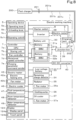
- FIG. 1 is an electrical block diagram of the electric working machine 1.
- a charging system S includes the electric working machine 1 and an external fast charger 200.
- FIG. 1 illustrates the electric working machine 1 connected to the fast charger 200 via a charging cable 201.
- the operating device 5 of the electric working machine 1 includes operating lever(s) 5a and an unloading lever 5b.
- the operating lever 5a and the unloading lever 5b can be operated by the operator seated in the operator's seat 4.
- the operating device 5 also includes a manual operator 5c.
- a controller 7 is located inside the machine body 2 or the protection structure 6 and includes a CPU 7a and a storing unit (memory and/or storage) 7b.
- the CPU 7a controls the operation of elements of the electric working machine 1 (electric motor 9, battery unit 30, inverter 38, each device, and/or the like) as shown in FIG. 1 .
- the storing unit 7b includes one or more memories and/or the like.
- Information, data, and program(s) e.g., control program(s) for the CPU 7a to control the operation of the elements are stored in the storing unit 7b in a read-write format.
- a starter switch 8 is located inside the protection structure 6 and can be operated by the operator seated in the operator's seat 4.
- the starter switch 8 is operated by the operator to start and stop the electric working machine 1. Specifically, when the starter switch 8 is turned on, the controller 7 starts up elements of the electric working machine 1. When the starter switch 8 is turned off, the controller 7 stops the elements of the electric working machine 1.
- the electric motor 9 is a drive for the electric working machine 1, which is, for example, a permanent magnet embedded three-phase AC synchronous motor.
- the inverter 38 is a motor drive to drive the electric motor 9.
- the inverter 38 is connected to the electric motor 9 and a junction box 39.
- the junction box 39 is connected to the inverter 38 as well as to a battery unit 30, a DC-DC converter 40, and a charging port 41.
- the junction box 39 outputs electricity outputted from the battery unit 30 to the inverter 38 and DC-DC converter 40.
- the inverter 38 converts direct current (DC) electricity inputted from the battery unit 30 via the junction box 39 into three-phase alternating current (AC) electricity and supplies the three-phase AC electricity to the electric motor 9. With this, the electric motor 9 is driven.
- the inverter 38 can adjust the electric current and voltage of the electricity supplied to the electric motor 9 as appropriate.
- the controller 7 controls the operation of the inverter 38 to drive or stop the electric motor 9.
- the DC-DC converter 40 is a voltage converter that converts the DC voltage inputted from the battery unit 30 via the junction box 39 into a different voltage.
- the DC-DC converter 40 is a step-down converter that converts the high voltage of the battery unit 30 to a predetermined low voltage corresponding to electrical component(s) in the electric working machine 1.
- the DC-DC converter 40 supplies electricity to a low-voltage battery 33 after voltage conversion.
- the above electrical component(s) includes, for example, the controller 7, fan motors 35a, 37a, and 42b and other equipment (such as a connection detector 41a, an electric heater 42, an electric cooler 46, a fluid temperature detector 47, a room temperature detector 48, a water temperature detector 49, and a display 123) which are described later.
- the charging port 41 can be connected to the charging cable 201.
- the charging port 41 is a receptacle (receiving connector) into which a connector 202 of the charging cable 201 is fitted, and includes a connection detector 41a.
- the charging port 41 is connected to the external fast charger 200 via the charging cable 201.
- the connection detector 41a includes a sensor and/or the like that detects that the charging cable 201 is connected to the charging port 41 and thus the external fast charger 200 is connected.
- the external fast charger 200 is capable of outputting large electric current (e.g., as much as about 125 amperes (A)), and has a power output of, for example, 125 A ⁇ 500 volts (V). Note that the fast charger 200 is not limited to those with the power output described above, but may be a charger with a power output of 400 A ⁇ 1000 V, for example.
- the charging cable 201 includes an electric power line 201a, a controller area network (CAN) signal line 201b, and an analog line 201c.
- CAN controller area network
- the fast charger 200 transmits a charging start signal to the electric working machine 1 via the analog line 201c.
- the electric working machine 1 transmits battery information to the fast charger 200 via the CAN signal line 201b.
- the fast charger 200 transmits charger information (operating status) of the fast charger 200 to the electric working machine 1 via the CAN signal line 201b.
- the electric working machine 1 transmits a ready signal to the fast charger 200 via the analog line 201c.
- the fast charger 200 transmits a charging enabling signal to the electric working machine 1 via the analog line 201c.
- the electric working machine 1 transmits charging parameter(s) (electric current command) to the fast charger 200 via the CAN signal line 201b at predetermined intervals (e.g., every 100 ms).
- the fast charger 200 outputs DC electric current according to the charging parameter(s) (electric current command) to the battery unit 30 of the electric working machine 1 via the electric power line 201a.
- the electric working machine 1 transmits a charging stop request to the fast charger 200 via the analog line 201c for the completion of charging or abnormal termination.
- the charging communication standard is not limited to CHAdeMO (registered trademark), but other charging methods based on other charging communication standards may be used.
- the junction box 39 outputs the electricity inputted from the external fast charger 200 through the charging cable 201 and the charging port 41 to the battery unit 30.
- the battery unit 30 is charged with the electricity inputted from the charging port 41 through the junction box 39.
- the battery unit 30 includes a plurality of batteries 31 and 32.
- Each of the batteries 31 and 32 is a secondary battery (storage battery), such as a lithium-ion battery, including at least one battery cell. If each of the batteries 31 and 32 includes multiple battery cells, the multiple battery cells are electrically connected in series and/or parallel.
- Each of the batteries 31 and 32 includes a plurality of internal cells, which are electrically connected in series and/or parallel.
- Each of the batteries 31 and 32 has an electrical capacity to operate element(s) of the electric working machine 1 for a given amount of time.
- the batteries 31 and 32 are connected in parallel with each other.
- the battery unit 30 includes two batteries 31 and 32, but the number of the batteries in the battery unit 30 is not limited to two, but can be one, three or more.
- the batteries 31 and 32 include respective connection switchers 31a and 32a.
- Each of the connection switchers 31a and 32a includes a relay, a switch, and/or the like, for example, and can switch between a connected state and a disconnected state.
- the controller 7 switches one of the connection switchers 31a and 32a to the connected state and the other to the disconnected state, thus outputting electricity from one of the batteries 31 and 32 to the junction box 39 and stopping the output of electricity from the other.
- the controller 7 controls output of electricity from the batteries 31 and 32 and controls the stop of output of electricity from the batteries 31 and 32.
- the controller 7 also switches the connection state inside the junction box 39 to connect or disconnect the inverter 38, the DC-DC converter 40, and/or the charging port 41 to or from each of the batteries 31 and 32.
- the junction box 39 and the connection switchers 31a and 32a are connection switchers that switch between connection and disconnection of the inverter 38, the DC-DC converter 40, and the charging port 41 to and from each of the batteries 31 and 32.
- the batteries 31 and 32 include respective battery management units (BMU; battery monitors) 31b and 32b.
- BMU battery management units
- the BMUs 31b and 32b are located within the corresponding the batteries 31 and 32, but may be located outside the batteries 31 and 32.
- the BMU 31b monitors and controls the corresponding battery 31.
- the BMU 32b monitors and controls the corresponding battery 32.
- the BMUs 31b and 32b control the opening and closing of relays inside the batteries 31 and 32 to control the start and stop of electricity supply from the batteries 31 and 32 to the junction box 39.
- the BMUs 31b and 32b monitor the status of the batteries 31 and 32.
- the BMUs 31b and 32b detect the temperature, voltage, electric current, terminal voltage across internal cell(s), and/or like of the batteries 31 and 32.
- the BMUs 31b and 32b detect the remaining charge level of the batteries 31 and 32 by a voltage measurement method based on the terminal voltage across the cell(s) inside the batteries 31 and 32, for example.
- the method of detecting the remaining charge level of the batteries 31 and 32 is not limited to voltage measurement, but may be other methods such as coulomb counting, battery cell modeling, impedance tracking, or the like.
- a remaining charge detector 34 which detects the remaining charge level in the batteries 31 and 32, may be provided separately from the BMUs 31b and 32b.
- the electric working machine 1 includes two BMUs 31b and 32b, but the electric working machine 1 may include only one BMU 31b. In such a case, one BMU 31b monitors and controls both the batteries 31 and 32.
- the low-voltage battery 33 is a lower voltage storage battery than the battery unit 30.
- the low-voltage battery 33 is charged with electricity supplied from the DC-DC converter 40.
- Th low-voltage battery 33 supplies electricity to electrical component(s) in the electric working machine 1.
- the remaining charge detector 34 is an electrical circuit that detects the remaining charge level of the low-voltage battery 33.
- the radiator 35 cools coolant for high-heat generating electric equipment such as the electric motor 9, the inverter 38, the DC-DC converter 40, and the battery unit 30.
- the high-heat-generating electric equipment is electric equipment that, by operating on electricity, generates more heat than other electric equipment in the electric working machine 1.
- the coolant is not water alone, but is a liquid that does not freeze even in cold weather, for example.
- the radiator 35 includes a fan motor 35a, as well as a radiator fan 35f rotated and driven by power from the fan motor 35a and a heat exchanger 35b (shown in FIG. 5 later).
- the fan motor 35a is driven by electricity from the low-voltage battery 33.
- a cooling pump 36 is provided in a coolant passage (not illustrated) located in the machine body 2, together with the radiator 35 and the high-heat-generating electric equipment mentioned above.
- the cooling pump 36 allows coolant to be discharged into and circulate through the coolant passage.
- An oil cooler 37 cools hydraulic fluid having passed through the hydraulic devices such as the aforementioned travel motors (left travel motor ML and right travel motor MR), swivel motor MT, and hydraulic actuators C1 to C5, hydraulic pumps P1, P2 and a control valve unit V (illustrated in FIG. 4 , etc.) which will be described later, and/or the like.
- the oil cooler 37 includes a fan motor 37a, as well as an oil cooler fan 37f rotated and driven by power from the fan motor 37a and a heat exchanger 37b (shown in FIG. 5 later).
- the fan motor 37a is driven by electricity from the low-voltage battery 33.
- the electric heater 42 is driven by electricity from the low-voltage battery 33 to heat the interior of the protection structure 6.
- the electric heater 42 is an electric heater and includes electric heating wire(s) 42a, a fan motor 42b, and a heating fan (not illustrated).
- the electric heating wire 42a emits high heat when energized.
- the fan motor 42b rotates and drives the heating fan.
- the heating fan blows ambient air heated by the electric heating wire 42a toward the interior of the protection structure 6.
- the fan motor 42b is driven by electricity from the low-voltage battery 33.
- the electric cooler 46 includes, for example, an air conditioner.
- the electric cooler 46 is driven by electricity from the low-voltage battery 33 to cool the interior of the protection structure 6.
- the electric heater 42 and the electric cooler 46 are air conditioning units that provide air conditioning inside the protection structure 6.
- the fluid temperature detector 47 is a sensor that detects the temperature (fluid temperature) of hydraulic fluid.
- the room temperature detector 48 is a sensor that detects the temperature (room temperature) inside the protection structure 6.
- the water temperature detector 49 is a sensor that detects the temperature (water temperature) of coolant.
- the controller 7 includes a fan controller 7c.
- the fan controller 7c controls the drive of the fan motor 35a of the radiator 35.
- the fan controller 7c controls the drive of the fan motor 35a of the radiator 35 so that the temperature of the coolant does not exceed a set temperature, based on the temperature of the coolant detected by the water temperature detector 49 and on a preset control map. If the temperature of hydraulic fluid detected by the fluid temperature detector 47 is below a predetermined value, the fan controller 7c stops the drive of the fan motor 37a of the oil cooler 37, and if the temperature of hydraulic fluid detected by the fluid temperature detector 47 is equal to or above the predetermined value, the fan controller 7c, based on a preset control map, controls the temperature of the hydraulic fluid so that the temperature does not exceed the set temperature.
- the manual operator 5c includes an operating switch 5c1 used during a normal period to set the motor rotational speed of the electric motor 9.
- the operating switch 5c1 is, for example, a rotational speed operating actuator and can receive, as a set value from the operator, any value within the range of the motor rotational speed of the electric motor 9 (e.g., 1500 to 2600 rpm). For example, if the operating switch 5c1 indicates the position of the tortoise symbol, the motor rotational speed is at its minimum value (e.g., 1500 rpm), and if the operating switch 5c1 indicates the position of the rabbit symbol, the motor rotational speed is at its maximum value (e.g., 2600 rpm).
- the controller 7 receives the operation on the manual operator 5c (e.g., operating switch 5c1) as the operation to set the motor rotational speed of the electric motor 9 when the charging cable 201 is not connected to the charging port 41.
- the controller 7 includes a rotational speed controller 7d.
- the rotational speed controller 7d controls the rotation of the electric motor 9 at the motor rotational speed set via the operating switch 5c1.
- the operating switch 5cl can be used to set charging parameter(s) during a charging period other than the normal period.
- the controller 7 receives the operation on the manual operator 5c (e.g., operating switch 5c1) as the operation to set the charging parameter(s) when the charging cable 201 is connected to the charging port 41.
- the charging parameter(s) includes at least one of electric current value, charging time, charging amount, or charging speed.
- the operating switch 5c1 makes it possible to, during the normal period, set the motor rotational speed of the electric motor 9, and, during the charging period, set the charging parameter.
- the manual operator 5c includes an indicator 5c2.
- the indicator 5c2 is, for example, a light-emitting diode, which turns off during the normal period (when setting the motor rotational speed) and turns on during the charging period (when setting the charging parameter). Note that the indicator 5c2 may turn on during the normal period (when setting the motor rotational speed) and turn off during the charging period (when setting the charging parameter).
- the indicator 5c2 may be a text indicator that indicates the operating status such as "normal state” or "charging state”.
- the manual operator 5c includes an indicator 5c3.
- the indicator 5c3 is an indicator of the operating position of the operating switch 5c1.
- the indicator 5c3, for example, includes unit markings which are segments of the range from the minimum value to the maximum value. The unit markings from the minimum value to the operating position of the operating switch 5c1 are illuminated.
- the controller 7 changes the value of electric current supplied from the fast charger 200 to the battery unit 30 using the charging parameter set via the manual operator 5c (e.g., operating switch 5c1). Specifically, the controller 7 includes a charging parameter command sender 7e to output, during the charging period, the charging parameter set via the operating switch 5c1 to the external fast charger 200 through the charging cable 201.
- the external fast charger 200 changes the value of electric current (DC electric current output) to be supplied to the battery unit 30 of the electric working machine 1 based on the charging parameter sent from the charging parameter command sender 7e.
- the BMU 31b and the BMU 32b have the same configuration, the BMU 31b will be described and the description for the BMU 32b will be omitted. That is, the configuration including the BMU 31b, the controller 7, and the battery 31 described below is equivalent to the configuration including the BMU 32b, the controller 7, and the battery 32.
- the BMU 31b is capable of deciding the permissible range of the charging parameter based on the status of the battery 31 (e.g., the temperature of the battery 31). For example, in the case where the charging parameter is electric current value, the BMU 31b sets the charging parameter to a first value (for example, an electric current value of 50 A) if the temperature of the battery 31 is a first temperature (e.g., low temperature) sufficiently lower than the use limit temperature of the battery 31 (the preset temperature at and above which the charging electric current value and/or output electric current value need(s) to be suppressed to prevent or reduce a temperature rise of the battery 31), and sets the permissible range to a first permissible range with the first value being the upper limit.
- a first temperature e.g., low temperature
- the BMU 31b sets the charging parameter to a second value (for example, an electric current value of 30 A) and sets the permissible range to a second permissible range with the second value being the upper limit.
- the number of the permissible ranges for the charging parameter is not limited to two, but may be three or more.
- the first and second values are not limited to the above values.
- the first value may be about 120 A and the second value may be about 80 A, as long as the values satisfy the relationship "the first value for the first permissible range > the second value for the second permissible range (the same applies below).
- the BMU 31b is capable of deciding the permissible range for the charging parameter based on the status of the battery 31 (e.g., the temperature of the battery 1). In other words, instead of causing the BMU 31b to perform uniform charging using the maximum electric current of the fast charger 200 (e.g., 125 A), it is possible to cause the BMU 31b to adjust the value of electric current outputted from the fast charger 200 appropriately.
- the maximum electric current of the fast charger 200 e.g., 125 A
- the charging parameter is charging time
- the BMU 31b sets the charging parameter to a first value (e.g., 60 minutes) and sets the permissible range to a first permissible range with the first value being the upper limit
- the BMU 31b sets the charging parameter to a second value (e.g., 30 minutes) and sets the permissible range to a second permissible range with the second value being the upper limit.
- the charging parameter is charging amount
- the BMU 31b sets the charging parameter to a first value (for example, the charging amount per unit time is 80%), and sets the permissible range to a first permissible range with the first value being the upper limit.
- the BMU 31b sets the charging parameter to a second value (for example, the charging amount per unit time is 40%) and sets the permissible range to a second permissible range with the second value being the upper limit.
- the charging parameter is charging speed
- the BMU 31b sets the charging parameter to a first value (e.g., high speed) and sets the permissible range to a first permissible range with the first value being the upper limit.
- the BMU 31b sets the charging parameter to a second value (e.g., medium speed) and sets the permissible range to a second permissible range with the second value being the upper limit.
- the controller 7 is capable of causing the display 123 to display the permissible range decided by the BMU 31b, and, if the charging parameter set via the operating switch 5c1 is included in the permissible range, outputting the charging parameter to the fast charger 200, and if the charging parameter is not included in the permissible range, not outputting the charging parameter and causing the display 123 to display a prompt to set the charging parameter again.
- the controller 7 causes the display 123 to display the charging parameter set via the operating switch 5c1 and the temperature of the battery 31 detected by the BMU 31b.
- the operating switch 5c1 can be used to set a changed charging parameter.
- the controller 7 e.g., the charging parameter command sender 7e
- the controller 7 changes the charging parameter set via the operating switch 5c1 to a changed charging parameter for the temperature of the battery 31 to decrease below the preset temperature.
- the charging parameter command sender 7e outputs the changed charging parameter to the fast charger 200 through the charging cable 201.
- the BMU 31b calculates estimated charging time using the target charging level of the battery 31, the remaining charge level of the battery 31, the charging parameter(s) set via the operating switch 5c1, and the charging amount per unit time.
- the estimated charging time is the time taken for the battery to be charged to the target charging level.
- the controller 7 causes the display 123 to display the estimated charging time.
- the BMU 31b determines whether or not to stop charging the battery 31 based on at least one of the temperature, electric current, voltage, remaining charge level, or charging time of the battery 31.
- the controller 7 e.g., the charging parameter command sender 7e
- FIG. 4 shows a hydraulic circuit K of the electric working machine 1.
- the hydraulic circuit K includes hydraulic devices including the hydraulic actuators C1 to C5, the travel motors (left travel motor ML and right travel motor MR), the swivel motor MT, the control valve unit V, the hydraulic pumps P1 and P2, a hydraulic fluid tank T, the oil cooler 37, operating valves PV1 to PV6, an unloading valve 58, a fluid passage 50, and/or the like.
- the hydraulic pump P1 is a hydraulic pump for actuation
- the hydraulic pump P2 is a hydraulic pump for control.
- the hydraulic pumps P1 and P2 are driven by power from the electric motor 9.
- the hydraulic pump P1 (hydraulic pump for actuation) suctions hydraulic fluid stored in the hydraulic fluid tank T and delivers the hydraulic fluid toward the control valve unit V.
- a single hydraulic pump P1 (hydraulic pump for actuation) is illustrated for convenience, but this does not imply any limitation.
- the number of the hydraulic pumps P1 may be selected as appropriate to allow hydraulic fluid to be supplied to the hydraulic actuators C1 to C5, travel motors (left travel motor ML and right travel motor MR), and swivel motor MT.
- the hydraulic pump P2 suctions hydraulic fluid stored in the hydraulic fluid tank T and then delivers the hydraulic fluid, thus outputting hydraulic pressure for signaling, controlling or the like.
- the hydraulic pump P2 (hydraulic pump for control) supplies (delivers) pilot fluid.
- the number of the hydraulic pumps P2 (hydraulic pumps for control) may also be selected appropriately.
- the control valve unit V includes multiple control valves V1 to V8.
- the control valves V1 to V8 control (adjust) the flow rate of hydraulic fluid outputted from the hydraulic pumps P1 and P2 to the hydraulic actuators C1 to C5, the left travel motor ML, the right travel motor MR, and the swivel motor MT.
- control valve V1 (swing control valve) controls the flow rate of hydraulic fluid to be supplied to the hydraulic actuator C1 (swing cylinder).
- the control valve V2 (boom control valve) controls the flow rate of hydraulic fluid to be supplied to the hydraulic actuator C2 (boom cylinder).
- the control valve V3 (arm control valve) controls the flow rate of hydraulic fluid to be supplied to the hydraulic actuator C3 (arm cylinder).
- the control valve V4 (bucket control valve) controls the flow rate of hydraulic fluid to be supplied to the hydraulic actuator C4 (bucket cylinder).
- control valve V5 (dozer control valve) controls the flow rate of hydraulic fluid to be supplied to the hydraulic actuator C5 (dozer cylinder).
- the control valve V6 left travel control valve
- the control valve V7 (right travel control valve) controls the flow rate of hydraulic fluid to be supplied to the right travel motor MR.
- the control valve V8 swivel control valve
- the operating valves PV1 to PV6 are actuated according to the operation of operating levers 5a ( FIG. 1 ) of the operating device 5.
- pilot fluid acts on the control valve(s) V1 to V8, thus moving the spool(s) of the control valve(s) V1 to V8.
- hydraulic fluid in an amount proportional to the amount by which the spool(s) of the control valve(s) V1 to V8 is/are moved is supplied to the to-be-controlled hydraulic actuator(s) C1 to C5, left travel motor ML, right travel motor MR, and/or the swivel motor MT.
- the hydraulic actuator(s) C1 to C5 the left travel motor ML, the right travel motor MR, and/or the swivel motor MT is/are driven according to the supply amount of hydraulic fluid from the control valve(s) V1 to V8.
- hydraulic fluid (pilot fluid) acting on the control valve(s) V1 to V8 is adjusted by operating the operating lever(s) 5a, so that the control valve(s) V1 to V8 is/are controlled.
- the amount of hydraulic fluid supplied from the control valve(s) V1 to V8 to the hydraulic actuator(s) C1 to C5, the left travel motor ML, the right travel motor MR, and/or the swivel motor MT is adjusted, so that the driving and stopping of the hydraulic actuator(s) C1 to C5, the left travel motor ML, the right travel motor MR, and the swivel motor MT are controlled.
- the fluid passage 50 includes a hose or a tube made of a material such as, for example, metal.
- the fluid passage 50 is a flow path that connects elements (hydraulic devices) in the hydraulic circuit K and allows hydraulic fluid or pilot fluid to flow to the element(s).
- the fluid passage 50 includes a first fluid passage 51, a second fluid passage 52, a first suction passage 54, a second suction passage 55, and a restriction fluid passage 57.
- the first suction passage 54 is a flow path to allow hydraulic fluid suctioned from the hydraulic fluid tank T by the hydraulic pump P1 (hydraulic pump for actuation) to flow therein.
- the second suction passage 55 is a flow path to allow hydraulic fluid suctioned from the hydraulic fluid tank T by the hydraulic pump P2 (hydraulic pump for control) to flow therein.
- the first fluid passage 51 is a flow path to allow hydraulic fluid delivered by the hydraulic pump P1 (hydraulic pump for actuation) to flow toward the control valves V1 to V8 of the control valve unit V.
- the first fluid passage 51 branches into multiple branches in the control valve unit V and connected to the control valves V1 to V8.
- the second fluid passage 52 includes flow path(es) to allow hydraulic fluid having passed through the control valves V1 to V8 to flow toward the hydraulic fluid tank T.
- the hydraulic fluid tank T stores hydraulic fluid.
- the second fluid passage 52 includes shuttle fluid passage(s) 52a and a drain passage 52b.
- a plurality of the shuttle fluid passages 52a are provided such that each of the control valves V1 to V8 is connected to a corresponding one of the to-be controlled hydraulic actuators C1 to C5, left travel motor ML, right travel motor MR, and swivel motor MT by a pair of the shuttle fluid passages 52a.
- Each shuttle fluid passage 52a is a flow path to supply hydraulic fluid from a connected one of the control valves V1 to V8 to a connected one of the hydraulic actuators C1 to C5, left travel motor ML, right travel motor MR, and swivel motor MT, and from the one of the hydraulic actuator C1 to C5, left travel motor ML, right travel motor MR, and swivel motor MT back to the one of the control valves V1 to V8.
- One end of the drain passage 52b branches into multiple branches and connected to the control valves V1 to V8. The opposite end of the drain passage 52b is connected to the hydraulic fluid tank T.
- a portion of hydraulic fluid having flowed through the first fluid passage 51 to one of the control valves V1 to V8 passes through the one of the control valves V1 to V8 to one of the shuttle fluid passages 52a, and is supplied to a to-be-controlled one of the hydraulic actuators C1 to C5, left travel motor ML, right travel motor MR, and swivel motor MT. Then, hydraulic fluid discharged from the one of the hydraulic actuators C1 to C5, left travel motor ML, right travel motor MR, and swivel motor MT flows through the other of the shuttle fluid passages 52a back to the connected one of the control valves V1 to V8, passes through the one of the control valves V1 to V8, and flows to the drain passage 52b.
- the drain passage 52b is provided with an oil cooler 37.
- the oil cooler 37 cools hydraulic fluid having flowed from any of the control valves V1 to V8 through the drain passage 52b.
- the hydraulic fluid cooled by the oil cooler 37 returns to the hydraulic fluid tank T through the drain passage 52b.
- the fluid passages 54, 51, and 52 are arranged to allow hydraulic fluid to circulate through the hydraulic fluid tank T, hydraulic pump P1, and control valves V1 to V8 of the control valve unit V (a portion of hydraulic fluid circulates also through the hydraulic actuators C1 to C5, the left travel motor ML, the right travel motor MR, and the swivel motor MT).
- the restriction fluid passage 57 is a flow path to allow hydraulic fluid delivered by the hydraulic pump P2 (hydraulic pump for control) to flow to the operating valves PV1 to PV6.
- One end of the restriction fluid passage 57 is connected to the hydraulic pump P2 (hydraulic pump for control), and the opposite end branches into multiple branches and connected to the ports on the primary side (primary ports) of the operating valves PV1 to PV6.
- the restriction fluid passage 57 is provided with an unloading valve 58.
- the unloading valve 58 prohibits or restricts the drive of the hydraulic actuators C1 to C5, the left travel motor ML, the right travel motor MR, and the swivel motor MT, i.e., the drive of the working device 20, by cutting off the supply of hydraulic fluid from the hydraulic pump P1 (hydraulic pump for actuation) to the hydraulic actuators C1 to C5, the left travel motor ML, the right travel motor MR, and the swivel motor MT.
- the unloading valve 58 is switched between a supply position and a blocking position by the operator operating the unloading lever 5b.
- hydraulic fluid having been delivered by the hydraulic pump P2 (hydraulic pump for control) into the restriction fluid passage 57 is supplied to the operating valves PV1 to PV6, allowing the operation of the control valves V1 to V8.
- This also allows the operation of the hydraulic actuators C1 through C5, the left travel motor ML, the right travel motor MR, the swivel motor MT, the working device 20, and the traveling device 10.
- the hydraulic fluid discharged from the operating valves PV1 to PV6 returns to the hydraulic fluid tank T through another drain passage (not shown).
- FIG. 5 illustrates an example of the layout of the interior of the machine body 2 of the electric working machine 1.
- FIG. 5 shows the interior of the machine body 2 as viewed from above.
- the control valve unit V is located in front of the swivel bearing 3 (downstream in direction A1).
- the hydraulic fluid tank T is located to the right of the swivel bearing 3 and above the hydraulic actuator C1 (swing cylinder).
- a partition 80 is provided behind (downstream in backward direction A2) of the swivel bearing 3 such that the partition 80 is parallel to the width direction of the machine body 2.
- the partition 80 divides the interior space of the machine body 2 into front and rear sections.
- a rear room R is located behind the partition 80 (downstream in direction A2).
- the battery unit 30, the inverter 38, the junction box 39, the DC-DC converter 40, the hydraulic pumps P1 and P2, the electric motor 9, the radiator 35, the oil cooler 37, and/or the like are located in the rear room R.
- the batteries 31 and 32 of the battery unit 30 are arranged along the width direction of the machine body 2.
- the inverter 38, the junction box 39, and the DC-DC converter 40 are located above the batteries 31 and 32.
- the hydraulic pumps P1 and P2, the electric motor 9, the radiator 35, and the oil cooler 37 are located to the right of the battery unit 30.
- the electric motor 9 is located behind the hydraulic pumps P1 and P2.
- the radiator 35 is located above the electric motor 9.
- the heat exchanger 35b of the radiator 35 is located closer to the battery unit 30 than the radiator fan 35f is.
- the oil cooler 37 is located above the hydraulic pumps P1 and P2.
- the heat exchanger 37b of the oil cooler 37 is located closer to the battery unit 30 than the oil cooler fan 37f is.
- the partition 80 has a plurality of through holes 81, 82, and 83.
- the through holes 81, 82, and 83 are for insertion of, for example, hoses (not shown) which are the fluid passage 50, electrical wire(s), and/or the like.
- the through holes 81, 82, and 83 may also be used as vents.
- the protection structure 6 (operator cab 4R) is provided above the machine body 2.
- the following describes a process of charging the electric working machine 1 using the external fast charger 200, and the like.
- the BMU 31b has determined that the detected value of the remaining charge in the battery 31 is below a predetermined value and outputted, to the controller 7, a low charge signal indicating that remaining charge in the battery 31 is low.
- the detected value of the remaining charge in the battery 32 is above the predetermined value and that the BMU 32b has not outputted a low charge signal to the controller 7.
- the controller 7 Based on the low charge signal from the BMU 31b, the controller 7 causes the display 123 of the electric working machine 1 to display a message M1 suggesting charging, as shown in FIG. 6A .
- the message M1 is, for example, a message asking the user to perform charging.
- the display 123 includes a coolant temperature indicator 123a, as shown in FIG. 6A .
- the coolant temperature indicator 123a indicates the temperature of coolant detected by the water temperature detector 49.
- the display 123 also includes a remaining battery level indicator 123b, as shown in FIG. 6A .
- the remaining battery level indicator 123b indicates the remaining charge level of the battery unit 30 (e.g., batteries 31 and 32) detected at the BMU 31b.
- the remaining battery level indicator 123b indicates a lower one of the remaining charge levels of the batteries 31 and 32. It is noted here that the remaining charge level of the battery 31 is indicated because the remaining charge level of the battery 31 is low.
- the remaining battery level indicator 123b may selectively indicate the remaining charge level of the battery 31 or 32 according to the selection made via the operating device 5.
- the remaining battery level indicator 123b may indicate the remaining charge level of the combination of the batteries 31 and 32.
- FIG. 7A is a flowchart showing an example of the charging start process to charge the electric working machine 1 using the external fast charger 200.
- the CPU 7a of the controller 7 in FIG. 1 executes control program(s) stored in advance in the storing unit 7b, so that the controller 7 starts the charging start process as shown in FIG. 7A .
- the controller 7 determines whether or not a charging cable is connected (S1).
- the operator ensures that the external fast charger 200 and the electric working machine 1 are connected by the charging cable 201, as shown in FIG. 2 .
- the operator connects the connector 202 of the charging cable 201, which is connected to the external fast charger 200, to the charging port 41 of the electric working machine 1.
- the connection detector 41a outputs a connection detection signal to the controller 7 when the charging cable 201 is connected to the charging port 41, and does not output a connection detection signal to the controller 7 when the charging cable 201 is not connected to the charging port 41.
- the controller 7 selects a charging mode when the charging cable 201 is connected to the charging port 41 (Yes in S1) (S2).
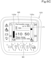
- the controller 7, for example, causes the display 123 to display a charging mode screen as shown in FIG. 6B .
- the controller 7 causes the display 123 to display the battery temperature indicator 123c as shown in FIG. 6B instead of the coolant temperature indicator 123a as shown in FIG. 6A .
- the battery temperature indicator 123c indicates the temperature of the battery unit 30 (e.g., battery 31) detected by the BMU 31b. It is noted here that the remaining charge level of the battery 31 is shown because the remaining charge level of the battery 31 is low.
- the controller 7 returns to S1 and waits until the charging cable 201 is connected.
- controller 7 After S2, the controller 7 performs controller area network (CAN) communication with the external fast charger 200 (S3).
- CAN controller area network
- the fast charger 200 transmits a charging start signal to the electric working machine 1 through the analog line 201c of the charging cable 201.
- the controller 7 of the electric working machine 1 starts CAN communication through the CAN signal line 201b and sends information about the battery 31 (e.g., maximum voltage, remaining charge level, maximum charging time of the battery 31) to the fast charger 200 through the CAN signal line 201b.
- the fast charger 200 sends charger information (e.g., maximum voltage, maximum electric current (e.g., 125 A), error threshold) to the electric working machine 1 through the CAN signal line 201b.
- the controller 7 of the electric working machine 1 evaluates the suitability of the fast charger 200 (determines whether the fast charger 200 is suitable for charging the battery 31) based on the charger information. If the controller 7 determines that the fast charger 200 is suitable for charging the battery 31, the controller 7 transmits a ready signal to the fast charger 200 via the analog line 201c. Upon receipt of the ready signal, the fast charger 200 performs insulation diagnosis, and, if the result of the insulation diagnosis is good, transmits a charging enabling signal to the electric working machine 1 via the analog line 201c.
- the controller 7 causes the display 123 to display the permissible range of the charging parameter (S4).
- the BMU 31b decides the permissible range of the charging parameter based on the status of the battery 31 (e.g., the temperature of battery 31).
- the BMU 31b sets the permissible range of the charging parameter to a first permissible range with a first value (for example, an electric current value of 50 A) being the upper limit, and if the temperature of the battery 31 is a second temperature lower than the use limit temperature of the battery 31 but higher than the first temperature (e.g., medium temperature), the BMU 31b sets the permissible range of the charging parameter to a second permissible range with a second value (for example, an electric current value of 30 A) being the upper limit.
- a first value for example, an electric current value of 50 A
- the BMU 31b sets the permissible range of the charging parameter to a second permissible range with a second value (for example, an electric current value of 30 A) being the upper limit.
- the controller 7 acquires the permissible range of the charging parameter set by the BMU 31b. Assume here that the permissible range of the charging parameter is set to the first permissible range with the first value (e.g., an electric current value of 50 A) being the upper limit. The controller 7 then acquires the permissible range of the charging parameter set by the BMU 31b and causes the display 123 to display the permissible range. The controller 7 causes the display 123 to display a message M2 (the message "permissible range: up to 50 A") indicating the permissible range of the charging parameter, as shown in FIG. 6B .
- M2 the message "permissible range: up to 50 A
- the controller 7 determines whether or not the charging parameter set via the operating switch 5c1 is included in the permissible range (S5).
- the controller 7 causes the display 123 to display, in in a display field F1, the charging parameter (for example, electric current value) set via the operating switch 5c1. If the charging parameter (for example, electric current value) displayed in the display field F1 is included in the permissible range (Yes in S5), the controller 7 accepts the setting of the charging parameter (S6) and outputs the charging parameter to the fast charger 200.
- the permissible range here is set to the first permissible range with the first value (e.g., an electric current value of 50 A) being the upper limit
- the controller 7 accepts the setting of the charging parameter. Assume here that an electric current value of 50 A has been set as the charging parameter by the operation of the operating switch 5c1 and is displayed in the display field F1 of the display 123.
- the controller 7 does not output the charging parameter, and causes the display 123 to display a prompt asking for re-setting and returns to S5. For example, if an electric current value exceeding 50 A (e.g., 100 A) is set via the operating switch 5c1, the controller 7 causes the display 123 to display a notice message stating that "Please set electric current value of 50 A or less", and does not output the charging parameter indicating an electric current value of 100 A to the fast charger 200.
- 50 A e.g. 100 A
- FIG. 7B is a flowchart showing an example of the charging control for the electric working machine.
- the controller 7 transmits, to the fast charger 200 through the CAN signal line 201b, an electric current value of 50 A which is the charging parameter set by the operation of the operating switch 5c1 in S6 (S71).
- the controller 7 determines whether or not the value of the temperature of the battery 31 detected by the BMU 31b is equal to or above a preset temperature that is lower than the use limit temperature of the battery 31 (S72). If the value of the temperature of the battery 31 is less than the preset temperature (No in S72), the controller 7 determines whether or not now is the time for transmission (S73). The time for transmission is after a predetermined period of time (e.g., 100 ms) from the last transmission of the charging parameter (in this case, an electric current value of 50 A), and comes repeatedly on a periodic basis. The counter function of the controller 7 allows detection of each time for transmission. If now is the time for transmission (Yes in S73), the controller 7 transmits the charging parameter (also an electric current value of 50 A) to the fast charger 200 through the CAN signal line 201b (S74).
- a predetermined period of time e.g. 100 ms
- the counter function of the controller 7 allows detection of each time for transmission. If now is the time for transmission (Yes in
- the controller 7 determines whether or not the status of the battery 31 detected by the BMU 31b is abnormal (S77).
- Abnormalities of the status of the battery 31 include, for example, abnormal temperature, abnormal electric current, and abnormal voltage of the battery 31.
- the controller 7 returns to S73 if the status of the battery 31 detected by the BMU 31b is not abnormal (No in S77).
- the controller 7 transmits a charging stop request to the fast charger 200 through the CAN signal line 201b to stop the DC electric current outputted by the fast charger 200 to stop charging (S82).
- the controller 7 may cause the display 123 to display a message indicating that the charging has been stopped. After S82, the controller 7 ends this process.
- the controller 7 causes the display 123 to display the estimated charging time calculated by the BMU 31b (S75).
- the target charging level e.g., 80%
- the BMU 31b calculates the estimated charging time using the target charging level of the battery 31, the remaining charge level of the battery 31, the charging parameter set via the manual operator 5c, and the charging amount per unit time. For example, the BMU 31b calculates the difference (e.g., 60%) between the target charging level (e.g., 80%) and the remaining charge level (e.g., 20%). The BMU 31b then calculates the charging amount per unit time using the charging parameter (electric current value of 50 A).
- the BMU 31b then divides the difference (e.g., 60%) by the charging amount per unit time (1%) to calculate 60 minutes.
- the controller 7 acquires the estimated charging time (e.g., 60 minutes) calculated by the BMU 31b.
- the controller 7 causes the display 123 to display the estimated charging time acquired from the BMU 31b.
- the controller 7 causes the display 123 to display a message M3 (the message "60 minutes to 80%") indicating the estimated charging time, as shown in FIG. 6B .
- the controller 7 determines whether or not to end charging based on the status of the battery 31 detected by the BMU 31b (S76). As described above, the target charging level (e.g., 80%) of the battery 31 is predetermined. The controller 7 determines that charging is completed (Yes in S76) when the charge level of the battery 31 reaches the target charging level (e.g., 80%) (in other words, when the remaining charge level of the battery 31 reaches 80%), and ends this process. Note that, in the case where the target charging time (for example, 60 minutes) of the battery 31 is predetermined, the controller 7 determines that charging is completed (Yes in S76) when the charging time of the battery 31 reaches the target charging time (for example, 60 minutes) and ends this process.
- the target charging time for example, 60 minutes
- the controller 7 determines that charging is completed (Yes in S76) when the BMU 31b detects that the battery 31 is fully charged (remaining charge level is "100%") and ends this process.
- the controller 7 determines that charging is not completed (No in S76) and returns to S72.
- the target charging level e.g., 100%
- the controller 7 determines that charging is not completed (No in S76) if the BMU 31b does not detect full charge (remaining charge level of "100%") of the battery 31, and returns to S72.
- the controller 7 sets a changed charging parameter (S78) if the value of the temperature of the battery 31 is the preset temperature or above (Yes in S72). Specifically, if the value of the temperature of the battery 31 is the preset temperature or above (Yes in S72), the controller 7 causes a message M4 asking for setting a changed charging parameter to be displayed, as shown in FIG. 6C .
- the message M4 is, for example, the message "Please change electric current value".
- the BMU 31b sets the charging parameter to a second value (e.g., an electric current value of 30 A) and sets the permissible range to the second permissible range with the second value being the upper limit.
- the controller 7 acquires the permissible range of the charging parameter set by the BMU 31b. Assume here that the permissible range of the charging parameter is set to the second permissible range with the second value (e.g., an electric current value of 30 A) being the upper limit.
- the controller 7 then acquires the permissible range of the charging parameter set by the BMU 31b and causes the display 123 to display the permissible range.
- the controller 7 causes the display 123 to display a message M5 (message "Permissible range: up to 30 A") indicating the permissible range of the charging parameter, as shown in FIG. 6C .
- the controller 7 determines whether or not the charging parameter set via the operating switch 5c1 is included in the permissible range. If the charging parameter set via the operating switch 5c1 is included in the permissible range, the controller 7 accepts the setting of the changed charging parameter (S78). Since the permissible range here is set to the second permissible range with the second value (e.g., an electric current value of 30 A) being the upper limit, if the changed charging parameter set via the operating switch 5c1 is an electric current value of 30 A or less, then the controller 7 accepts the setting of the changed charging parameter. Assume here that an electric current value of 30 A is set as the changed charging parameter by the operation of the operating switch 5c1. The controller 7 causes the display 123 to display, in the display field F1, the electric current value of 30 A as the changed charging parameter as shown in FIG. 6D .
- S78 the setting of the changed charging parameter
- the controller 7 remains at S78 until the changed charging parameter (for example, an electric current value of 30 A or less) included in the permissible range is set.
- the controller 7 allows the changed charging parameter to be set by the operation of the operating switch 5c1 by the operator, but this does not imply any limitation.
- the controller 7 may set the charging parameter automatically to the upper limit (second value) of the second permissible range (e.g., an electric current value of 30 A) without relying on the operation of the operating switch 5c1 by the operator. In such a case, the operator does not need to go through the trouble of performing setting operations, which is highly convenient.
- the controller 7 determines whether or not now is the time for transmission (S79). If now is the time for transmission (Yes in S79), the controller 7 transmits the changed charging parameter (electric current value of 30 A) to the fast charger 200 through CAN signal line 201b (S80).
- the controller 7 causes the display 123 to display the estimated charging time calculated by the BMU 31b (S75). Assume here that the calculated estimated charging time is "45 minutes”.
- the controller 7 acquires the estimated charging time (e.g., 45 minutes) calculated by the BMU 31b.
- the controller 7 causes the display 123 to display the estimated charging time acquired from the BMU 31b.
- the controller 7 causes the display 123 to display a message M6 (the message "40 minutes to 80%") indicating the estimated charging time, as shown in FIG. 6D .
- the controller 7 determines whether or not the status of the battery 31 detected by the BMU 31b is abnormal (S81).
- Abnormalities of the status of the battery 31 include, for example, abnormal temperature, abnormal electric current, and abnormal voltage of the battery 31.
- the controller 7 returns to S79 if the status of battery 31 detected by the BMU 31b is not abnormal (No in S81).
- the controller 7 transmits a charging stop request to the fast charger 200 through the CAN signal line 201b to stop the DC electric current output by the fast charger 200 to stop charging (S82). After S82, the controller 7 ends this process.
- An electric working machine 1 achieve the following effect(s).
- An electric working machine 1 includes an electric motor 9 (electric actuator), a battery unit 30 including a battery 31 to supply electricity to the electric motor 9, a working device 20 to operate using a driving force from the electric motor 9, a charging port 41 (connector) to be connected to an external fast charger 200 via a charging cable 201, a manual operator 5c to be operated to set at least one charging parameter, and a controller 7 to change a value of electric current supplied from the fast charger 200 to the battery unit 30 according to the at least one charging parameter set via the manual operator 5c.
- an electric motor 9 electric actuator
- a battery unit 30 including a battery 31 to supply electricity to the electric motor 9, a working device 20 to operate using a driving force from the electric motor 9, a charging port 41 (connector) to be connected to an external fast charger 200 via a charging cable 201, a manual operator 5c to be operated to set at least one charging parameter, and a controller 7 to change a value of electric current supplied from the fast charger 200 to the battery unit 30 according to the at least one charging parameter set via
- the manual operator 5c is operable to set at least one charging parameter which is a command for the fast charger 200.
- the controller 7 outputs the at least one charging parameter set via the manual operator 5c to the fast charger 200. With this configuration, it is possible to cause the fast charger 200 to charge the battery 31 of the battery unit 30 based on the charging parameter which is a command from the electric working machine to the external fast charger 200.
- the electric working machine further includes a display 123.
- the battery unit 30 includes a battery monitor 31b to monitor a status of the battery 31.
- the battery monitor 31b determines a permissible range of the at least one charging parameter based on the status of the battery 31.
- the controller 7 causes the display 123 to display the permissible range determined by the battery monitor 31b.
- the manual operator 5c is operable to set the at least one charging parameter within the permissible range. With this configuration, the permissible range of the at least one charging parameter is displayed on the display 123, allowing the operator to set a charging parameter included in the permissible range.
- the charging parameter is outputted to the fast charger 200, whereas, if the charging parameter is not included in the permissible range, the charging parameter is not outputted and a prompt for setting the charging parameter again is displayed by the display 123. That is, the charging parameter not included in the permissible range is not outputted but a prompt for setting the charging parameter again is displayed. This makes it possible to eliminate the likelihood that inappropriate charging parameters will be set.
- the electric working machine further includes a display 123.
- the battery unit 30 includes a battery monitor 31b to monitor a status of the battery 31.
- the battery monitor detects at least a temperature of the battery 31 as the status of the battery 31.
- the controller 7 causes the display123 to display the at least one charging parameter set via the manual operator 5c and the temperature of the battery 31 detected by the battery monitor 31b.
- the manual operator 5c is operable to change the set at least one charging parameter.
- the operator can change the at least one charging parameter while looking at the temperature of the battery 31 displayed on the display 123.
- the fast charger 200 charges the battery 31 of the battery unit 30 according to the changed charging parameter. Therefore, if the temperature of the battery 31 is high, it is possible to prevent or reduce the temperature rise of the battery 31 by reducing the value of the charging parameter. On the contrary, if the temperature of the battery 31 is low, it is possible to reduce the charging time by increasing the value of the charging parameter. That is, it is possible to appropriately change the charging parameter based on the relationship with the temperature of the battery 31.
- the controller 7 changes the at least one charging parameter set via the manual operator 5c to a changed charging parameter for the temperature of the battery 31 to decrease below the preset temperature.
- the electric working machine 1 it is possible to make full use of the electric working machine 1 immediately after the battery 31 is charged.
- the battery 31 when the battery 31 is quickly charged, the battery 31 may be hot (at the use limit temperature) immediately after being charged. If the battery 31 is hot immediately after being charged, a power output restriction is imposed on the electric motor 9, and the operation of the electric working machine is restricted or stopped, resulting in hindering work after charging.
- the electric working machine 1 according to one or more embodiments can prevent such a problem.
- the battery monitor 31b calculates an estimated charging time using a target charging level of the battery 31, a remaining charge level of the battery 31, the at least one charging parameter set via the manual operator 5c, and a charging amount per unit time, the estimated charging time being a time taken for the battery 31 to be charged to the target charging level.
- the controller 7 causes the display 123 to display the estimated charging time. With this configuration, the operator can check the estimated charging time on the display 123.
- the battery monitor 31b determines whether or not to stop charging the battery 31 based on at least one of a temperature, electric current, voltage, remaining charge level, or charging time of the battery 31.
- the controller 7 outputs a charging stop request to the fast charger 200 if the battery monitor 31b determines to stop charging. With this configuration, it is possible to cause the fast charger 200 to stop charging based on the result of monitoring of the status of the battery 31 by the battery monitor 31b.
- the electric actuator is an electric motor 9.
- the electric working machine further includes a hydraulic pump P1 to be driven by the electric motor 9 to deliver hydraulic fluid, a hydraulic device M to be driven by hydraulic fluid from the hydraulic pump P1, and a working device 20 to be actuated by the hydraulic device M.
- the manual operator 5c is to be used to set a motor rotational speed of the electric motor 9 during a normal period, and used to set the at least one charging parameter during a charging period other than the normal period. With this configuration, the manual operator 5c to be used to set the motor rotational speed can be used also to set the charging parameter(s), eliminating the need for additional components and making it possible to prevent or reduce an increase in parts count.
- the controller 7 receives an operation on the manual operator 5c as an operation to set the at least one charging parameter when the charging cable 201 is connected to the charging port 41, and receives the operation on the manual operator 5c as an operation to set the motor rotational speed of the electric motor 9 when the charging cable 201 is not connected to the charging port 41.
- the manual operator 5c upon connection of the charging cable 201 to the charging port 41, the manual operator 5c is allowed to set the at least one charging parameter, making it possible to switch the function of the manual operator 5c to the charging parameter setting function without time or effort.
- the manual operator 5c upon disconnection of the charging cable 201 from the charging port 41, the manual operator 5c is allowed to set the motor rotational speed of the electric motor 9, making it possible to easily change the function of the manual operator 5c back to the original function (the function of setting the motor rotational speed of the electric motor 9).
- the manual operator 5c is an operating switch 5c1 to set the motor rotational speed of the electric motor 9 during a normal period.
- the operating switch 5c1 is used to set the at least one charging parameter during a charging period other than the normal period. With this configuration, the operating switch 5c1 to set the motor rotational speed can be used also to set the at least one charging parameter, eliminating the need for additional components and making it possible to prevent or reduce an increase in parts count.
- the at least one charging parameter set via the manual operator 5c may include at least one of electric current value, charging time, charging level, or charging speed.
- at least one of electric current value, charging time, charging level, or charging speed can be set as the at least one charging parameter. This makes it possible to select the content of charging parameter (i.e., at least one of electric current value, charging time, charging level, or charging speed) corresponding to the operator's need and thus possible to improve the degree of freedom of operability.
- An electric working machine 1 may be configured such that the controller 7 receives an operation on the manual operator 5c as an operation to set the at least one charging parameter when an unloading valve 58 is in a blocking position, and the controller 7 receives the operation on the manual operator 5c as an operation to set the motor rotational speed of the electric motor 9 when the unloading valve 58 is in a supply position. That is, the controller 7 may be configured or programmed to not supply electric current from the fast charger 200 to the battery unit 30 when the unloading valve 58 is in the supply position.
- An electric working machine 1 may include a storing unit 7b to store, as the previously set value, a motor rotational speed indicated by the operating switch 5c1 immediately before the setting of the at least one charging parameter is allowed, and may be configured such that the controller 7 causes the display 123 to display the previously set value stored in the storing unit 7b when the operating switch 5c1 is allowed to set the motor rotational speed of the electric motor 9.
- the controller 7 causes the display 123 to display a level indicator LV1 which indicates the previously set value stored in the storing unit 7b. That is, the display 123 shows that the operating switch 5c1 was in the position corresponding to the level indicator LV1 when the motor rotational speed of the electric motor 9 was set.
- FIG. 8 illustrates an electric working machine 1 according to variation 3.
- FIG. 8 is an electrical block diagram of the electric working machine 1 according to variation 3.
- the electric working machine 1 according to variation 3 is such that the manual operator 5c is a display 124 including a display panel 124a and a touch panel 124b located on a front side of the display panel 124a, the motor rotational speed of the electric motor 9 can be set during a normal period, and the at least one charging parameter can be set during a charging period other than the normal period.
- the display 124 may be the display 123 as illustrated in FIGS. 6A to 6D that has a touch panel function and that is configured to display a graphical indication corresponding to the operating switch 5c1.
- the display 124 having the touch panel function can be used not only to set the motor rotational speed but also to set the at least one charging parameter, providing good operability.
- An electric working machine 1 according to variation 4 is such that the controller 7 stops the supply of electricity from the battery 31 to the electric motor 9 (electric actuator) while the fast charger 200 supplies electric current to the battery unit 30.
- the controller 7 upon the connection of the charging cable 201 to the charging port 41, the controller 7 causes the display 123 to display a selection screen for selection of a charging mode, and, upon selection of the charging mode, stops the electric motor 9 and keeps the electric motor 9 in the stopped state until the charging mode ends.
- the controller 7 causes the display 123 to display a selection screen for selection of a charging mode, and, upon selection of the charging mode, stops the electric motor 9 and keeps the electric motor 9 in the stopped state until the charging mode ends.
- the electric motor 9 is stopped, the battery 31 of the battery unit 30 starts being charged, and the electric motor 9 is kept in the stopped state during the charging mode.
- one or more or all of the actuators of the working device 20 and the traveling device 10 may be electric actuator(s), the electric actuator(s) may be driven by electricity from the battery(batteries) 31, 32, and the working device 20 and the traveling device 10 may be driven by power from the electric actuator(s).
- Another example other than the configuration in which all the actuators are electric actuators would be a configuration which includes at least one of an electric motor to drive hydraulic pump(s) or an electric swivel motor.
- the present invention is applicable not only to the electric working machine 1 such as a backhoe but also to, for example, some other construction machine such as a wheel loader, a compact track loader, or a skid-steer loader, as well as an agricultural machine such as a tractor, a combine, a rice transplanter, or a mower.
- some other construction machine such as a wheel loader, a compact track loader, or a skid-steer loader
- an agricultural machine such as a tractor, a combine, a rice transplanter, or a mower.
Landscapes
- Engineering & Computer Science (AREA)
- Power Engineering (AREA)
- Mechanical Engineering (AREA)
- Transportation (AREA)
- Mining & Mineral Resources (AREA)
- Civil Engineering (AREA)
- General Engineering & Computer Science (AREA)
- Structural Engineering (AREA)
- Life Sciences & Earth Sciences (AREA)
- Sustainable Development (AREA)
- Sustainable Energy (AREA)
- Charge And Discharge Circuits For Batteries Or The Like (AREA)
Abstract
Description
- The present invention relates to an electric working machine powered by one or more batteries and a charging system for an electric working machine.
-
Patent Literature 1 discloses an electric working machine (e.g., a hydraulic excavator) driven by electricity supplied from a rechargeable battery. In such an electric working machine, when the power remaining in the battery is low, quick charging is performed using an external fast charger. - PTL 1:
Japanese Unexamined Patent Application Publication No. 2021-80703 - During the quick charging, large electric current (e.g., about as much as 125 A) flows from the fast charger to the battery of the electric working machine, and therefore the battery can be fully charged in a short period of time, e.g., about an hour. Thus, for example, a full charge can be achieved by quick charging during a lunch break alone, but there is concern that the battery temperature may increase due to large electric current. In some cases, if the battery reaches the preset use limit temperature when the battery is charged, a power output restriction is imposed on the electric motor to prevent or reduce the temperature rise of the battery. This is because if the battery is used at a temperature above the use limit temperature, the useful life of the battery will not be ensured. Therefore, there are cases in which, because quick charging is performed even when the battery does not need to be charged in a short period of time, work after charging is hindered.
- The present invention was made in view of such problems of known techniques, and an object thereof is to reduce the likelihood that work done by the electric working machine after charging will be hindered.
- An electric working machine according to an aspect of the present invention includes an electric actuator, a battery unit including a battery to supply electricity to the electric actuator, a working device to operate using a driving force from the electric actuator, a connector to be connected to an external fast charger via a charging cable, a manual operator to be operated to set at least one charging parameter, and a controller to change a value of electric current supplied from the fast charger to the battery unit according to the at least one charging parameter set via the manual operator.
- The manual operator may be operated to set the at least one charging parameter which is a command for the fast charger. The controller may output the at least one charging parameter set via the manual operator to the fast charger.
- The electric working machine may further include a display. The battery unit may include a battery monitor to monitor a status of the battery. The battery monitor may determine a permissible range of the at least one charging parameter based on the status of the battery. The controller may cause the display to display the permissible range determined by the battery monitor. The manual operator may be operable to set the at least one charging parameter within the permissible range.
- The electric working machine according to an aspect of the present invention may further include a display. The battery unit may include a battery monitor to monitor a status of the battery. The battery monitor may detect at least a temperature of the battery as the status of the battery. The controller may cause the display to display the at least one charging parameter set via the manual operator and the temperature of the battery detected by the battery monitor. The manual operator may be operable to change the set at least one charging parameter.
- If the temperature of the battery detected by the battery monitor is equal to or above a preset temperature lower than a use limit temperature of the battery, the controller may change the at least one charging parameter set via the manual operator to a charging parameter for the temperature of the battery to decrease below the preset temperature.
- The battery monitor may calculate an estimated charging time using a target charging level of the battery, a remaining charge level of the battery, the at least one charging parameter set via the manual operator, and a charging amount per unit time, the estimated charging time being a time taken for the battery to be charged to the target charging level. The controller may cause the display to display the estimated charging time.
- The battery unit may include a battery monitor to monitor a status of the battery. The battery monitor may determine whether or not to stop charging the battery based on at least one of a temperature, electric current, voltage, remaining charge level, or charging time of the battery. The controller may output a charging stop request to the fast charger if the battery monitor determines to stop charging.
- The electric actuator may be an electric motor. The electric working machine may further include a hydraulic pump to be driven by the electric motor to deliver hydraulic fluid, a hydraulic device to be driven by hydraulic fluid from the hydraulic pump, and a working device to be actuated by the hydraulic device. The manual operator may be operable to be used to set a motor rotational speed of the electric motor during a normal period, and used to set the at least one charging parameter during a charging period other than the normal period.
- The controller may receive an operation on the manual operator as an operation to set the at least one charging parameter when the charging cable is connected to the connector, and receive the operation on the manual operator as an operation to set the motor rotational speed of the electric motor when the charging cable is not connected to the connector.
- The controller may stop supply of electricity from the battery to the electric actuator while the fast charger supplies electric current to the battery unit.
- The electric actuator may be an electric motor. The electric working machine may further include a hydraulic pump to be driven by the electric motor to deliver hydraulic fluid, a hydraulic device to be driven by hydraulic fluid from the hydraulic pump, a working device to be actuated by the hydraulic device, and an unloading valve switchable between a supply position in which hydraulic fluid from the hydraulic pump is supplied to the hydraulic device and a blocking position in which the hydraulic fluid from the hydraulic pump is not supplied to the hydraulic device. The controller may not supply electric current from the fast charger to the battery unit when the unloading valve is in the supply position.
- The at least one charging parameter set via the manual operator may include at least one of electric current value, charging time, charging amount, or charging speed.
- A charging system for an electric working machine according to an aspect of the present invention includes the electric working machine, and a fast charger to change a value of electric current supplied via the charging cable to the electric working machine according to a command from the electric working machine.
- With the above configuration, since the operator can set appropriate charging parameter(s) corresponding to the state and the manner in which an electric working machine is used, it is possible to reduce the likelihood that work done by the electric working machine after charging will be hindered.
-
- [
FIG. 1] FIG. 1 is an electric block diagram of an electric working machine. - [
FIG. 2] FIG. 2 illustrates an example of the manner in which the electric working machine and an external charger are connected by a charging cable for charging. - [
FIG. 3A] FIG. 3A illustrates an example of an operating switch. - [
FIG. 3B] FIG. 3B illustrates an example of an operating switch according tovariation 2. - [
FIG. 4] FIG. 4 is a hydraulic circuit diagram of an electric working machine - [
FIG. 5] FIG. 5 is a layout in a machine body of the electric working machine. - [
FIG. 6A] FIG. 6A illustrates an example of a display screen on a display. - [
FIG. 6B] FIG. 6B illustrates an example of a display screen on a display. - [
FIG. 6C] FIG. 6C illustrates an example of a display screen on a display. - [
FIG. 6D] FIG. 6D illustrates an example of a display screen on a display. - [
FIG. 7A] FIG. 7A is a flowchart showing an example of a charging start process performed on an electric working machine using an external charger. - [
FIG. 7B] FIG. 7B is a flowchart showing an example of charging control performed on an electric working machine. - [
FIG. 8] FIG. 8 is an electric block diagram of an electric working machine according tovariation 3. - [
FIG. 9] FIG. 9 is a general side view of an electric working machine. - Embodiments of the present invention will be described below with reference to the drawings.
- First, an overall configuration of an
electric working machine 1 is described. -
FIG. 9 is a general side view of the electric workingmachine 1. - The
electric working machine 1 is a backhoe. Theelectric working machine 1 includes a machine body (swivel base) 2, a travelingdevice 10, a workingdevice 20, and the like. Themachine body 2 is provided, thereon, with an operator'sseat 4 on which an operator is to be seated, and aprotection structure 6 that protects the operator'sseat 4 from front, back, left, right, and above. - The
protection structure 6 is also called a cabin. Theprotection structure 6 includes a frame attached to themachine body 2, a roof attached to an upper portion of the frame, and a plurality of side walls attached to the front, rear, and left and right sides of the frame, respectively (details not shown). Each side wall includes a transparent portion (so-called window) that allows the surroundings to be seen from the operator'sseat 4. Such aprotection structure 6 divides the space around the operator'sseat 4 from the outside. That is, theprotection structure 6 defines anoperator cab 4R including the operator'sseat 4. - There is an
operating device 5 to operate the electric workingmachine 1 in the vicinity of the operator'sseat 4 inside the protection structure 6 (operator cab 4R). The operator can operate theoperating device 5 while seated in the operator'sseat 4. - Note that, in the present embodiment, the direction in which the operator seated in the operator's
seat 4 faces (direction of arrow A1 inFIG. 9 ) is referred to as forward, and the opposite direction (direction of arrow A2 inFIG. 9 ) is referred to as backward. Furthermore, with the operator seated in the operator'sseat 4 and facing in the forward direction A1, the leftward direction from the operator is referred to as leftward and the rightward direction from the operator is referred to as rightward. A horizontal direction orthogonal to a front-back direction A3 of the electric workingmachine 1 is referred to as a vehicle body width direction. - The traveling
device 10 causes themachine body 2 to travel, and includes atravel frame 11 and atravel mechanism 12. The travel frame (truck frame) 11 is a structure to have thetravel mechanism 12 attached therearound and support themachine body 2 thereon. - The
travel mechanism 12 is, for example, a crawler travel mechanism. A plurality of thetravel mechanisms 12 are provided on the left and right sides of thetravel frame 11, respectively. Eachtravel mechanism 12 includes an idler 13, adrive wheel 14, a plurality of rollingwheels 15, anendless crawler belt 16, and a travel motor (left travel motor ML, right travel motor MR). - The idler 13 is located at a front portion of the
travel frame 11. Thedrive wheel 14 is located at a rear portion of thetravel frame 11. The plurality of rollingwheels 15 are provided between the idler 13 and thedrive wheel 14. Thecrawler belt 16 is wound over the idler 13, thedrive wheel 14, and the rollingwheels 15. - The left travel motor ML is included in the
travel mechanism 12 on the left side of thetravel frame 11. The right travel motor MR is included in thetravel mechanism 12 on the right side of thetravel frame 11. The left travel motor ML and the right travel motor MR are hydraulic motors. In eachtravel mechanism 12, power from the left travel motor ML or the right travel motor MR drives thedrive wheel 14 to rotate and drives thecrawler belt 16 in a circumferential motion. - A
dozer device 18 is provided at the front portion of the travelingdevice 10. Thedozer device 18 is pivoted up and down by the extension and retraction of a hydraulic actuator C5 (dozer cylinder). The hydraulic actuator C5 (dozer cylinder) is attached to thetravel frame 11. The hydraulic actuator C5 (dozer cylinder) is a hydraulic cylinder. - The
machine body 2 is supported on thetravel frame 11 via a swivel bearing 3 such that themachine body 2 is rotatable about a swivel axis X. A swivel motor MT is provided inside themachine body 2. The swivel motor MT is a hydraulic motor (hydraulic actuator included in a hydraulic device M). Themachine body 2 is rotated about the swivel axis X by power from the swivel motor MT. - The working
device 20 is supported at the front portion of themachine body 2. The workingdevice 20 includes aboom 21, anarm 22, a bucket (working tool) 23, and hydraulic actuators C1 to C5. The proximal portion of theboom 21 is pivotally attached to aswing bracket 24 such that theboom 21 is swingable about a lateral axis (an axis extending in the width direction of the machine body 2). Therefore, theboom 21 is swingable up and down (in the vertical direction). Thearm 22 is pivotally attached to the distal portion of theboom 21 such that thearm 22 is swingable about a lateral axis. Therefore, thearm 22 is swingable back and forth or up and down. Thebucket 23 is provided at the distal portion of thearm 22 such that thebucket 23 is capable of shoveling and dumping. - The
electric working machine 1 can have attached thereto another working tool (hydraulic attachment) which can be driven by a hydraulic actuator, instead of or in addition to thebucket 23. Examples of the other working tool include hydraulic breakers, hydraulic crushers, angle brooms, earth augers, pallet forks, sweepers, mowers, and snow blowers. - The
swing bracket 24 swings to the left and right upon extension and retraction of the hydraulic actuator C1 (swing cylinder) provided in themachine body 2. Theboom 21 swings up and down (back and forth) upon extension and retraction of the hydraulic actuator C2 (boom cylinder). Thearm 22 swings up and down (back and forth) upon extension and retraction of the hydraulic actuator C3 (arm cylinder). Thebucket 23 performs shoveling and dumping upon extension and retraction of the hydraulic actuator C4 (bucket cylinder, or working tool cylinder). The hydraulic actuator C1 (swing cylinder), the hydraulic actuator C2 (boom cylinder), the hydraulic actuator C3 (arm cylinder), and the hydraulic actuator C4 (bucket cylinder) are hydraulic cylinders. - The
electric working machine 1 performs work using the above-describedtraveling device 10 including the travel motors (left travel motors ML and right travel motor MR) and the hydraulic actuator C5, the workingdevice 20 including the hydraulic actuators C1 to C4, the swivel motor MT, and/or the like. The travel motors (left travel motor ML and right travel moto MR), the swivel motor MT, and the hydraulic actuators C1 to C5 are included in the hydraulic device M.The traveling device 10 is also a working device which is included in the electric workingmachine 1. - Next, an electrical configuration of the electric working
machine 1 is described. -
FIG. 1 is an electrical block diagram of the electric workingmachine 1. A charging system S includes the electric workingmachine 1 and an externalfast charger 200.FIG. 1 illustrates the electric workingmachine 1 connected to thefast charger 200 via a chargingcable 201. - The operating
device 5 of the electric workingmachine 1 includes operating lever(s) 5a and an unloadinglever 5b. The operatinglever 5a and the unloadinglever 5b can be operated by the operator seated in the operator'sseat 4. The operatingdevice 5 also includes amanual operator 5c. - A
controller 7 is located inside themachine body 2 or theprotection structure 6 and includes aCPU 7a and a storing unit (memory and/or storage) 7b. TheCPU 7a controls the operation of elements of the electric working machine 1 (electric motor 9,battery unit 30,inverter 38, each device, and/or the like) as shown inFIG. 1 . The storingunit 7b includes one or more memories and/or the like. Information, data, and program(s) (e.g., control program(s)) for theCPU 7a to control the operation of the elements are stored in thestoring unit 7b in a read-write format. - A
starter switch 8 is located inside theprotection structure 6 and can be operated by the operator seated in the operator'sseat 4. Thestarter switch 8 is operated by the operator to start and stop the electric workingmachine 1. Specifically, when thestarter switch 8 is turned on, thecontroller 7 starts up elements of the electric workingmachine 1. When thestarter switch 8 is turned off, thecontroller 7 stops the elements of the electric workingmachine 1. - The
electric motor 9 is a drive for the electric workingmachine 1, which is, for example, a permanent magnet embedded three-phase AC synchronous motor. Theinverter 38 is a motor drive to drive theelectric motor 9. Theinverter 38 is connected to theelectric motor 9 and ajunction box 39. - The
junction box 39 is connected to theinverter 38 as well as to abattery unit 30, a DC-DC converter 40, and a chargingport 41. Thejunction box 39 outputs electricity outputted from thebattery unit 30 to theinverter 38 and DC-DC converter 40. - The
inverter 38 converts direct current (DC) electricity inputted from thebattery unit 30 via thejunction box 39 into three-phase alternating current (AC) electricity and supplies the three-phase AC electricity to theelectric motor 9. With this, theelectric motor 9 is driven. Theinverter 38 can adjust the electric current and voltage of the electricity supplied to theelectric motor 9 as appropriate. Thecontroller 7 controls the operation of theinverter 38 to drive or stop theelectric motor 9. - The DC-
DC converter 40 is a voltage converter that converts the DC voltage inputted from thebattery unit 30 via thejunction box 39 into a different voltage. In the present embodiment, the DC-DC converter 40 is a step-down converter that converts the high voltage of thebattery unit 30 to a predetermined low voltage corresponding to electrical component(s) in the electric workingmachine 1. The DC-DC converter 40 supplies electricity to a low-voltage battery 33 after voltage conversion. The above electrical component(s) includes, for example, thecontroller 7,fan motors connection detector 41a, anelectric heater 42, anelectric cooler 46, afluid temperature detector 47, aroom temperature detector 48, awater temperature detector 49, and a display 123) which are described later. - The charging port 41 (connector) can be connected to the charging
cable 201. For example, the chargingport 41 is a receptacle (receiving connector) into which a connector 202 of the chargingcable 201 is fitted, and includes aconnection detector 41a. The chargingport 41 is connected to the externalfast charger 200 via the chargingcable 201. Theconnection detector 41a includes a sensor and/or the like that detects that the chargingcable 201 is connected to the chargingport 41 and thus the externalfast charger 200 is connected. - The external
fast charger 200 is capable of outputting large electric current (e.g., as much as about 125 amperes (A)), and has a power output of, for example, 125 A × 500 volts (V). Note that thefast charger 200 is not limited to those with the power output described above, but may be a charger with a power output of 400 A × 1000 V, for example. - As illustrated in
FIG. 2 , when the electric workingmachine 1 and thefast charger 200 are connected together by the chargingcable 201, for example, charging is performed using a known charging communication standard. In the present embodiment, the case in which charging is performed using, for example, CHAdeMO (registered trademark) charging communication standard is described. The chargingcable 201 includes anelectric power line 201a, a controller area network (CAN)signal line 201b, and ananalog line 201c. - For example, the
fast charger 200 transmits a charging start signal to the electric workingmachine 1 via theanalog line 201c. Theelectric working machine 1 transmits battery information to thefast charger 200 via theCAN signal line 201b. Thefast charger 200 transmits charger information (operating status) of thefast charger 200 to the electric workingmachine 1 via theCAN signal line 201b. Theelectric working machine 1 transmits a ready signal to thefast charger 200 via theanalog line 201c. Thefast charger 200 transmits a charging enabling signal to the electric workingmachine 1 via theanalog line 201c. Theelectric working machine 1 transmits charging parameter(s) (electric current command) to thefast charger 200 via theCAN signal line 201b at predetermined intervals (e.g., every 100 ms). Thefast charger 200 outputs DC electric current according to the charging parameter(s) (electric current command) to thebattery unit 30 of the electric workingmachine 1 via theelectric power line 201a. Theelectric working machine 1 transmits a charging stop request to thefast charger 200 via theanalog line 201c for the completion of charging or abnormal termination. Note that the charging communication standard is not limited to CHAdeMO (registered trademark), but other charging methods based on other charging communication standards may be used. - The
junction box 39 outputs the electricity inputted from the externalfast charger 200 through the chargingcable 201 and the chargingport 41 to thebattery unit 30. Thebattery unit 30 is charged with the electricity inputted from the chargingport 41 through thejunction box 39. - The
battery unit 30 includes a plurality ofbatteries batteries batteries batteries batteries machine 1 for a given amount of time. Thebatteries - In the present embodiment, the
battery unit 30 includes twobatteries battery unit 30 is not limited to two, but can be one, three or more. - The
batteries respective connection switchers connection switchers - The
controller 7 switches one of theconnection switchers batteries junction box 39 and stopping the output of electricity from the other. In other words, thecontroller 7 controls output of electricity from thebatteries batteries - The
controller 7 also switches the connection state inside thejunction box 39 to connect or disconnect theinverter 38, the DC-DC converter 40, and/or the chargingport 41 to or from each of thebatteries junction box 39 and theconnection switchers inverter 38, the DC-DC converter 40, and the chargingport 41 to and from each of thebatteries - The
batteries FIG. 1 , theBMUs batteries batteries - The
BMU 31b monitors and controls the correspondingbattery 31. TheBMU 32b monitors and controls the correspondingbattery 32. Specifically, theBMUs batteries batteries junction box 39. Furthermore, theBMUs batteries BMUs batteries - In addition, the
BMUs batteries batteries batteries charge detector 34, which detects the remaining charge level in thebatteries BMUs - Note that in the present embodiment, the electric working
machine 1 includes two BMUs 31b and 32b, but the electric workingmachine 1 may include only oneBMU 31b. In such a case, oneBMU 31b monitors and controls both thebatteries - The low-
voltage battery 33 is a lower voltage storage battery than thebattery unit 30. The low-voltage battery 33 is charged with electricity supplied from the DC-DC converter 40. Th low-voltage battery 33 supplies electricity to electrical component(s) in the electric workingmachine 1. The remainingcharge detector 34 is an electrical circuit that detects the remaining charge level of the low-voltage battery 33. - The
radiator 35 cools coolant for high-heat generating electric equipment such as theelectric motor 9, theinverter 38, the DC-DC converter 40, and thebattery unit 30. The high-heat-generating electric equipment is electric equipment that, by operating on electricity, generates more heat than other electric equipment in the electric workingmachine 1. The coolant is not water alone, but is a liquid that does not freeze even in cold weather, for example. - The
radiator 35 includes afan motor 35a, as well as aradiator fan 35f rotated and driven by power from thefan motor 35a and aheat exchanger 35b (shown inFIG. 5 later). Thefan motor 35a is driven by electricity from the low-voltage battery 33. - A cooling
pump 36 is provided in a coolant passage (not illustrated) located in themachine body 2, together with theradiator 35 and the high-heat-generating electric equipment mentioned above. The coolingpump 36 allows coolant to be discharged into and circulate through the coolant passage. - An
oil cooler 37 cools hydraulic fluid having passed through the hydraulic devices such as the aforementioned travel motors (left travel motor ML and right travel motor MR), swivel motor MT, and hydraulic actuators C1 to C5, hydraulic pumps P1, P2 and a control valve unit V (illustrated inFIG. 4 , etc.) which will be described later, and/or the like. Theoil cooler 37 includes afan motor 37a, as well as an oilcooler fan 37f rotated and driven by power from thefan motor 37a and aheat exchanger 37b (shown inFIG. 5 later). Thefan motor 37a is driven by electricity from the low-voltage battery 33. - The
electric heater 42 is driven by electricity from the low-voltage battery 33 to heat the interior of theprotection structure 6. Theelectric heater 42 is an electric heater and includes electric heating wire(s) 42a, afan motor 42b, and a heating fan (not illustrated). Theelectric heating wire 42a emits high heat when energized. Thefan motor 42b rotates and drives the heating fan. The heating fan blows ambient air heated by theelectric heating wire 42a toward the interior of theprotection structure 6. Thefan motor 42b is driven by electricity from the low-voltage battery 33. - The
electric cooler 46 includes, for example, an air conditioner. Theelectric cooler 46 is driven by electricity from the low-voltage battery 33 to cool the interior of theprotection structure 6. Theelectric heater 42 and theelectric cooler 46 are air conditioning units that provide air conditioning inside theprotection structure 6. - The
fluid temperature detector 47 is a sensor that detects the temperature (fluid temperature) of hydraulic fluid. Theroom temperature detector 48 is a sensor that detects the temperature (room temperature) inside theprotection structure 6. Thewater temperature detector 49 is a sensor that detects the temperature (water temperature) of coolant. - The
controller 7 includes afan controller 7c. Thefan controller 7c controls the drive of thefan motor 35a of theradiator 35. For example, thefan controller 7c controls the drive of thefan motor 35a of theradiator 35 so that the temperature of the coolant does not exceed a set temperature, based on the temperature of the coolant detected by thewater temperature detector 49 and on a preset control map. If the temperature of hydraulic fluid detected by thefluid temperature detector 47 is below a predetermined value, thefan controller 7c stops the drive of thefan motor 37a of theoil cooler 37, and if the temperature of hydraulic fluid detected by thefluid temperature detector 47 is equal to or above the predetermined value, thefan controller 7c, based on a preset control map, controls the temperature of the hydraulic fluid so that the temperature does not exceed the set temperature. - As shown in
FIG. 3A , themanual operator 5c includes an operating switch 5c1 used during a normal period to set the motor rotational speed of theelectric motor 9. The operating switch 5c1 is, for example, a rotational speed operating actuator and can receive, as a set value from the operator, any value within the range of the motor rotational speed of the electric motor 9 (e.g., 1500 to 2600 rpm). For example, if the operating switch 5c1 indicates the position of the tortoise symbol, the motor rotational speed is at its minimum value (e.g., 1500 rpm), and if the operating switch 5c1 indicates the position of the rabbit symbol, the motor rotational speed is at its maximum value (e.g., 2600 rpm). - The
controller 7 receives the operation on themanual operator 5c (e.g., operating switch 5c1) as the operation to set the motor rotational speed of theelectric motor 9 when the chargingcable 201 is not connected to the chargingport 41. Thecontroller 7 includes arotational speed controller 7d. Therotational speed controller 7d controls the rotation of theelectric motor 9 at the motor rotational speed set via the operating switch 5c1. - The operating switch 5cl can be used to set charging parameter(s) during a charging period other than the normal period. Specifically, the
controller 7 receives the operation on themanual operator 5c (e.g., operating switch 5c1) as the operation to set the charging parameter(s) when the chargingcable 201 is connected to the chargingport 41. The charging parameter(s) includes at least one of electric current value, charging time, charging amount, or charging speed. - As described above, the operating switch 5c1 makes it possible to, during the normal period, set the motor rotational speed of the
electric motor 9, and, during the charging period, set the charging parameter. As illustrated inFIG. 3A , themanual operator 5c includes an indicator 5c2. The indicator 5c2 is, for example, a light-emitting diode, which turns off during the normal period (when setting the motor rotational speed) and turns on during the charging period (when setting the charging parameter). Note that the indicator 5c2 may turn on during the normal period (when setting the motor rotational speed) and turn off during the charging period (when setting the charging parameter). The indicator 5c2 may be a text indicator that indicates the operating status such as "normal state" or "charging state". Themanual operator 5c includes an indicator 5c3. The indicator 5c3 is an indicator of the operating position of the operating switch 5c1. The indicator 5c3, for example, includes unit markings which are segments of the range from the minimum value to the maximum value. The unit markings from the minimum value to the operating position of the operating switch 5c1 are illuminated. - The
controller 7 changes the value of electric current supplied from thefast charger 200 to thebattery unit 30 using the charging parameter set via themanual operator 5c (e.g., operating switch 5c1). Specifically, thecontroller 7 includes a chargingparameter command sender 7e to output, during the charging period, the charging parameter set via the operating switch 5c1 to the externalfast charger 200 through the chargingcable 201. The externalfast charger 200 changes the value of electric current (DC electric current output) to be supplied to thebattery unit 30 of the electric workingmachine 1 based on the charging parameter sent from the chargingparameter command sender 7e. - Since the
BMU 31b and theBMU 32b have the same configuration, theBMU 31b will be described and the description for theBMU 32b will be omitted. That is, the configuration including theBMU 31b, thecontroller 7, and thebattery 31 described below is equivalent to the configuration including theBMU 32b, thecontroller 7, and thebattery 32. - The
BMU 31b is capable of deciding the permissible range of the charging parameter based on the status of the battery 31 (e.g., the temperature of the battery 31). For example, in the case where the charging parameter is electric current value, theBMU 31b sets the charging parameter to a first value (for example, an electric current value of 50 A) if the temperature of thebattery 31 is a first temperature (e.g., low temperature) sufficiently lower than the use limit temperature of the battery 31 (the preset temperature at and above which the charging electric current value and/or output electric current value need(s) to be suppressed to prevent or reduce a temperature rise of the battery 31), and sets the permissible range to a first permissible range with the first value being the upper limit. If the temperature of thebattery 31 is a second temperature (e.g., medium temperature) lower than the use limit temperature of thebattery 31 but higher than the first temperature, then theBMU 31b sets the charging parameter to a second value (for example, an electric current value of 30 A) and sets the permissible range to a second permissible range with the second value being the upper limit. The number of the permissible ranges for the charging parameter is not limited to two, but may be three or more. The first and second values are not limited to the above values. For example, the first value may be about 120 A and the second value may be about 80 A, as long as the values satisfy the relationship "the first value for the first permissible range > the second value for the second permissible range (the same applies below). Thus, theBMU 31b is capable of deciding the permissible range for the charging parameter based on the status of the battery 31 (e.g., the temperature of the battery 1). In other words, instead of causing theBMU 31b to perform uniform charging using the maximum electric current of the fast charger 200 (e.g., 125 A), it is possible to cause theBMU 31b to adjust the value of electric current outputted from thefast charger 200 appropriately. - In a case that the charging parameter is charging time, if the temperature of the
battery 31 is the first temperature, theBMU 31b sets the charging parameter to a first value (e.g., 60 minutes) and sets the permissible range to a first permissible range with the first value being the upper limit, and if the temperature of thebattery 31 is the second temperature, theBMU 31b sets the charging parameter to a second value (e.g., 30 minutes) and sets the permissible range to a second permissible range with the second value being the upper limit. In a case that the charging parameter is charging amount, if the temperature of thebattery 31 is the first temperature, theBMU 31b sets the charging parameter to a first value (for example, the charging amount per unit time is 80%), and sets the permissible range to a first permissible range with the first value being the upper limit. If the temperature of thebattery 31 is the second temperature, theBMU 31b sets the charging parameter to a second value (for example, the charging amount per unit time is 40%) and sets the permissible range to a second permissible range with the second value being the upper limit. In a case that the charging parameter is charging speed, if the temperature of thebattery 31 is the first temperature, theBMU 31b sets the charging parameter to a first value (e.g., high speed) and sets the permissible range to a first permissible range with the first value being the upper limit. If the temperature of thebattery 31 is the second temperature, theBMU 31b sets the charging parameter to a second value (e.g., medium speed) and sets the permissible range to a second permissible range with the second value being the upper limit. - The
controller 7 is capable of causing thedisplay 123 to display the permissible range decided by theBMU 31b, and, if the charging parameter set via the operating switch 5c1 is included in the permissible range, outputting the charging parameter to thefast charger 200, and if the charging parameter is not included in the permissible range, not outputting the charging parameter and causing thedisplay 123 to display a prompt to set the charging parameter again. - The
controller 7 causes thedisplay 123 to display the charging parameter set via the operating switch 5c1 and the temperature of thebattery 31 detected by theBMU 31b. The operating switch 5c1 can be used to set a changed charging parameter. The controller 7 (e.g., the chargingparameter command sender 7e) outputs the changed charging parameter to thefast charger 200 through the chargingcable 201 when the changed charging parameter is set via the operating switch 5c1. - If the value of the temperature of the
battery 31 detected by theBMU 31b is equal to or higher than a preset temperature that is lower than the use limit temperature of thebattery 31, thecontroller 7 changes the charging parameter set via the operating switch 5c1 to a changed charging parameter for the temperature of thebattery 31 to decrease below the preset temperature. The chargingparameter command sender 7e outputs the changed charging parameter to thefast charger 200 through the chargingcable 201. - The
BMU 31b calculates estimated charging time using the target charging level of thebattery 31, the remaining charge level of thebattery 31, the charging parameter(s) set via the operating switch 5c1, and the charging amount per unit time. The estimated charging time is the time taken for the battery to be charged to the target charging level. Thecontroller 7 causes thedisplay 123 to display the estimated charging time. - The
BMU 31b determines whether or not to stop charging thebattery 31 based on at least one of the temperature, electric current, voltage, remaining charge level, or charging time of thebattery 31. The controller 7 (e.g., the chargingparameter command sender 7e) outputs a charging stop request to thefast charger 200 if theBMU 31b determines to stop charging. - Next, the following description discusses a hydraulic circuit of the electric working
machine 1. -
FIG. 4 shows a hydraulic circuit K of the electric workingmachine 1. - The hydraulic circuit K includes hydraulic devices including the hydraulic actuators C1 to C5, the travel motors (left travel motor ML and right travel motor MR), the swivel motor MT, the control valve unit V, the hydraulic pumps P1 and P2, a hydraulic fluid tank T, the
oil cooler 37, operating valves PV1 to PV6, an unloadingvalve 58, afluid passage 50, and/or the like. - The hydraulic pump P1 is a hydraulic pump for actuation, and the hydraulic pump P2 is a hydraulic pump for control. The hydraulic pumps P1 and P2 are driven by power from the
electric motor 9. - The hydraulic pump P1 (hydraulic pump for actuation) suctions hydraulic fluid stored in the hydraulic fluid tank T and delivers the hydraulic fluid toward the control valve unit V. In
FIG. 4 , a single hydraulic pump P1 (hydraulic pump for actuation) is illustrated for convenience, but this does not imply any limitation. The number of the hydraulic pumps P1 (hydraulic pumps for actuation) may be selected as appropriate to allow hydraulic fluid to be supplied to the hydraulic actuators C1 to C5, travel motors (left travel motor ML and right travel motor MR), and swivel motor MT. - The hydraulic pump P2 (hydraulic pump for control) suctions hydraulic fluid stored in the hydraulic fluid tank T and then delivers the hydraulic fluid, thus outputting hydraulic pressure for signaling, controlling or the like. Specifically, the hydraulic pump P2 (hydraulic pump for control) supplies (delivers) pilot fluid. The number of the hydraulic pumps P2 (hydraulic pumps for control) may also be selected appropriately.
- The control valve unit V includes multiple control valves V1 to V8. The control valves V1 to V8 control (adjust) the flow rate of hydraulic fluid outputted from the hydraulic pumps P1 and P2 to the hydraulic actuators C1 to C5, the left travel motor ML, the right travel motor MR, and the swivel motor MT.
- Specifically, the control valve V1 (swing control valve) controls the flow rate of hydraulic fluid to be supplied to the hydraulic actuator C1 (swing cylinder). The control valve V2 (boom control valve) controls the flow rate of hydraulic fluid to be supplied to the hydraulic actuator C2 (boom cylinder). The control valve V3 (arm control valve) controls the flow rate of hydraulic fluid to be supplied to the hydraulic actuator C3 (arm cylinder). The control valve V4 (bucket control valve) controls the flow rate of hydraulic fluid to be supplied to the hydraulic actuator C4 (bucket cylinder). The control valve V5 (dozer control valve) controls the flow rate of hydraulic fluid to be supplied to the hydraulic actuator C5 (dozer cylinder). The control valve V6 (left travel control valve) controls the flow rate of hydraulic fluid to be supplied to the left travel motor ML. The control valve V7 (right travel control valve) controls the flow rate of hydraulic fluid to be supplied to the right travel motor MR. The control valve V8 (swivel control valve) controls the flow rate of hydraulic fluid to be supplied to the swivel motor MT.
- The operating valves PV1 to PV6 are actuated according to the operation of
operating levers 5a (FIG. 1 ) of theoperating device 5. In proportion to the amount by which the operating valve(s) PV1 to PV6 is/are actuated (operation amount of the operating valves PV1 to PV6), pilot fluid acts on the control valve(s) V1 to V8, thus moving the spool(s) of the control valve(s) V1 to V8. Then, hydraulic fluid in an amount proportional to the amount by which the spool(s) of the control valve(s) V1 to V8 is/are moved is supplied to the to-be-controlled hydraulic actuator(s) C1 to C5, left travel motor ML, right travel motor MR, and/or the swivel motor MT. Furthermore, the hydraulic actuator(s) C1 to C5, the left travel motor ML, the right travel motor MR, and/or the swivel motor MT is/are driven according to the supply amount of hydraulic fluid from the control valve(s) V1 to V8. - In other words, hydraulic fluid (pilot fluid) acting on the control valve(s) V1 to V8 is adjusted by operating the operating lever(s) 5a, so that the control valve(s) V1 to V8 is/are controlled. With this, the amount of hydraulic fluid supplied from the control valve(s) V1 to V8 to the hydraulic actuator(s) C1 to C5, the left travel motor ML, the right travel motor MR, and/or the swivel motor MT is adjusted, so that the driving and stopping of the hydraulic actuator(s) C1 to C5, the left travel motor ML, the right travel motor MR, and the swivel motor MT are controlled.
- The
fluid passage 50 includes a hose or a tube made of a material such as, for example, metal. Thefluid passage 50 is a flow path that connects elements (hydraulic devices) in the hydraulic circuit K and allows hydraulic fluid or pilot fluid to flow to the element(s). Thefluid passage 50 includes afirst fluid passage 51, asecond fluid passage 52, afirst suction passage 54, asecond suction passage 55, and arestriction fluid passage 57. - The
first suction passage 54 is a flow path to allow hydraulic fluid suctioned from the hydraulic fluid tank T by the hydraulic pump P1 (hydraulic pump for actuation) to flow therein. Thesecond suction passage 55 is a flow path to allow hydraulic fluid suctioned from the hydraulic fluid tank T by the hydraulic pump P2 (hydraulic pump for control) to flow therein. - The
first fluid passage 51 is a flow path to allow hydraulic fluid delivered by the hydraulic pump P1 (hydraulic pump for actuation) to flow toward the control valves V1 to V8 of the control valve unit V. Thefirst fluid passage 51 branches into multiple branches in the control valve unit V and connected to the control valves V1 to V8. - The
second fluid passage 52 includes flow path(es) to allow hydraulic fluid having passed through the control valves V1 to V8 to flow toward the hydraulic fluid tank T. The hydraulic fluid tank T stores hydraulic fluid. Thesecond fluid passage 52 includes shuttle fluid passage(s) 52a and adrain passage 52b. - A plurality of the
shuttle fluid passages 52a are provided such that each of the control valves V1 to V8 is connected to a corresponding one of the to-be controlled hydraulic actuators C1 to C5, left travel motor ML, right travel motor MR, and swivel motor MT by a pair of theshuttle fluid passages 52a. Eachshuttle fluid passage 52a is a flow path to supply hydraulic fluid from a connected one of the control valves V1 to V8 to a connected one of the hydraulic actuators C1 to C5, left travel motor ML, right travel motor MR, and swivel motor MT, and from the one of the hydraulic actuator C1 to C5, left travel motor ML, right travel motor MR, and swivel motor MT back to the one of the control valves V1 to V8. One end of thedrain passage 52b branches into multiple branches and connected to the control valves V1 to V8. The opposite end of thedrain passage 52b is connected to the hydraulic fluid tank T. - A portion of hydraulic fluid having flowed through the
first fluid passage 51 to one of the control valves V1 to V8 passes through the one of the control valves V1 to V8 to one of theshuttle fluid passages 52a, and is supplied to a to-be-controlled one of the hydraulic actuators C1 to C5, left travel motor ML, right travel motor MR, and swivel motor MT. Then, hydraulic fluid discharged from the one of the hydraulic actuators C1 to C5, left travel motor ML, right travel motor MR, and swivel motor MT flows through the other of theshuttle fluid passages 52a back to the connected one of the control valves V1 to V8, passes through the one of the control valves V1 to V8, and flows to thedrain passage 52b. - The other portion of the hydraulic fluid having flowed through the
first fluid passage 51 to one of the control valves V1 to V8 flows through the one of the control valves V1 to V8 to thedrain passage 52b without being supplied to the hydraulic actuators C1 to C5, the left travel motor ML, the right travel motor MR or the swivel motor MT. Thedrain passage 52b is provided with anoil cooler 37. Theoil cooler 37 cools hydraulic fluid having flowed from any of the control valves V1 to V8 through thedrain passage 52b. - The hydraulic fluid cooled by the
oil cooler 37 returns to the hydraulic fluid tank T through thedrain passage 52b. As mentioned above, thefluid passages - The
restriction fluid passage 57 is a flow path to allow hydraulic fluid delivered by the hydraulic pump P2 (hydraulic pump for control) to flow to the operating valves PV1 to PV6. One end of therestriction fluid passage 57 is connected to the hydraulic pump P2 (hydraulic pump for control), and the opposite end branches into multiple branches and connected to the ports on the primary side (primary ports) of the operating valves PV1 to PV6. - The
restriction fluid passage 57 is provided with an unloadingvalve 58. The unloadingvalve 58 prohibits or restricts the drive of the hydraulic actuators C1 to C5, the left travel motor ML, the right travel motor MR, and the swivel motor MT, i.e., the drive of the workingdevice 20, by cutting off the supply of hydraulic fluid from the hydraulic pump P1 (hydraulic pump for actuation) to the hydraulic actuators C1 to C5, the left travel motor ML, the right travel motor MR, and the swivel motor MT. - Specifically, the unloading
valve 58 is switched between a supply position and a blocking position by the operator operating the unloadinglever 5b. Once the unloadingvalve 58 has switched to the supply position, hydraulic fluid having been delivered by the hydraulic pump P2 (hydraulic pump for control) into therestriction fluid passage 57 is supplied to the operating valves PV1 to PV6, allowing the operation of the control valves V1 to V8. This also allows the operation of the hydraulic actuators C1 through C5, the left travel motor ML, the right travel motor MR, the swivel motor MT, the workingdevice 20, and the travelingdevice 10. The hydraulic fluid discharged from the operating valves PV1 to PV6 returns to the hydraulic fluid tank T through another drain passage (not shown). - On the contrary, once the unloading
valve 58 has switched to the blocking position, hydraulic fluid having been delivered by the hydraulic pump P2 (hydraulic pump for control) into therestriction fluid passage 57 is drained to the hydraulic fluid tank T, and is no longer supplied (stops being supplied) to the operating valves PV1 to PV6, and the operation of the control valves V1 to V8 is prohibited or restricted. With this, the operation of the hydraulic actuators C1 to C5, the left travel motor ML, the right travel motor MR, the swivel motor MT, the workingdevice 20, and the travelingdevice 10 is also prohibited or restricted. - Next, the layout of the interior of the
machine body 2 of the electric workingmachine 1 is described. -
FIG. 5 illustrates an example of the layout of the interior of themachine body 2 of the electric workingmachine 1.FIG. 5 shows the interior of themachine body 2 as viewed from above. In themachine body 2, the control valve unit V is located in front of the swivel bearing 3 (downstream in direction A1). The hydraulic fluid tank T is located to the right of theswivel bearing 3 and above the hydraulic actuator C1 (swing cylinder). Apartition 80 is provided behind (downstream in backward direction A2) of the swivel bearing 3 such that thepartition 80 is parallel to the width direction of themachine body 2. Thepartition 80 divides the interior space of themachine body 2 into front and rear sections. - A rear room R is located behind the partition 80 (downstream in direction A2). The
battery unit 30, theinverter 38, thejunction box 39, the DC-DC converter 40, the hydraulic pumps P1 and P2, theelectric motor 9, theradiator 35, theoil cooler 37, and/or the like are located in the rear room R. - The
batteries battery unit 30 are arranged along the width direction of themachine body 2. Theinverter 38, thejunction box 39, and the DC-DC converter 40 are located above thebatteries - The hydraulic pumps P1 and P2, the
electric motor 9, theradiator 35, and theoil cooler 37 are located to the right of thebattery unit 30. Theelectric motor 9 is located behind the hydraulic pumps P1 and P2. Theradiator 35 is located above theelectric motor 9. Theheat exchanger 35b of theradiator 35 is located closer to thebattery unit 30 than theradiator fan 35f is. Theoil cooler 37 is located above the hydraulic pumps P1 and P2. Theheat exchanger 37b of theoil cooler 37 is located closer to thebattery unit 30 than the oilcooler fan 37f is. - The
partition 80 has a plurality of throughholes fluid passage 50, electrical wire(s), and/or the like. The through holes 81, 82, and 83 may also be used as vents. The protection structure 6 (operator cab 4R) is provided above themachine body 2. - The following describes a process of charging the electric working
machine 1 using the externalfast charger 200, and the like. Assume here that theBMU 31b has determined that the detected value of the remaining charge in thebattery 31 is below a predetermined value and outputted, to thecontroller 7, a low charge signal indicating that remaining charge in thebattery 31 is low. Assume also that the detected value of the remaining charge in thebattery 32 is above the predetermined value and that theBMU 32b has not outputted a low charge signal to thecontroller 7. Based on the low charge signal from theBMU 31b, thecontroller 7 causes thedisplay 123 of the electric workingmachine 1 to display a message M1 suggesting charging, as shown inFIG. 6A . The message M1 is, for example, a message asking the user to perform charging. - The
display 123 includes acoolant temperature indicator 123a, as shown inFIG. 6A . Thecoolant temperature indicator 123a indicates the temperature of coolant detected by thewater temperature detector 49. - The
display 123 also includes a remainingbattery level indicator 123b, as shown inFIG. 6A . The remainingbattery level indicator 123b indicates the remaining charge level of the battery unit 30 (e.g.,batteries 31 and 32) detected at theBMU 31b. For example, the remainingbattery level indicator 123b indicates a lower one of the remaining charge levels of thebatteries battery 31 is indicated because the remaining charge level of thebattery 31 is low. Note that the remainingbattery level indicator 123b may selectively indicate the remaining charge level of thebattery operating device 5. The remainingbattery level indicator 123b may indicate the remaining charge level of the combination of thebatteries - Upon receipt of the low charge signal from the
BMU 31b, thecontroller 7 performs a charging start process as shown inFIG. 7A. FIG. 7A is a flowchart showing an example of the charging start process to charge the electric workingmachine 1 using the externalfast charger 200. Specifically, theCPU 7a of thecontroller 7 inFIG. 1 executes control program(s) stored in advance in thestoring unit 7b, so that thecontroller 7 starts the charging start process as shown inFIG. 7A . - The
controller 7 determines whether or not a charging cable is connected (S1). The operator ensures that the externalfast charger 200 and the electric workingmachine 1 are connected by the chargingcable 201, as shown inFIG. 2 . Specifically, the operator connects the connector 202 of the chargingcable 201, which is connected to the externalfast charger 200, to the chargingport 41 of the electric workingmachine 1. - The
connection detector 41a outputs a connection detection signal to thecontroller 7 when the chargingcable 201 is connected to the chargingport 41, and does not output a connection detection signal to thecontroller 7 when the chargingcable 201 is not connected to the chargingport 41. Thecontroller 7 selects a charging mode when the chargingcable 201 is connected to the charging port 41 (Yes in S1) (S2). Thecontroller 7, for example, causes thedisplay 123 to display a charging mode screen as shown inFIG. 6B . Once thecontroller 7 has selected the charging mode, thecontroller 7 causes thedisplay 123 to display thebattery temperature indicator 123c as shown inFIG. 6B instead of thecoolant temperature indicator 123a as shown inFIG. 6A . Thebattery temperature indicator 123c indicates the temperature of the battery unit 30 (e.g., battery 31) detected by theBMU 31b. It is noted here that the remaining charge level of thebattery 31 is shown because the remaining charge level of thebattery 31 is low. - On the contrary, if the charging
cable 201 is not connected to the charging port 41 (No in S1), thecontroller 7 returns to S1 and waits until the chargingcable 201 is connected. - After S2, the
controller 7 performs controller area network (CAN) communication with the external fast charger 200 (S3). - Specifically, the
fast charger 200 transmits a charging start signal to the electric workingmachine 1 through theanalog line 201c of the chargingcable 201. Upon receipt of the charging start signal from thefast charger 200, thecontroller 7 of the electric workingmachine 1 starts CAN communication through theCAN signal line 201b and sends information about the battery 31 (e.g., maximum voltage, remaining charge level, maximum charging time of the battery 31) to thefast charger 200 through theCAN signal line 201b. Thefast charger 200 sends charger information (e.g., maximum voltage, maximum electric current (e.g., 125 A), error threshold) to the electric workingmachine 1 through theCAN signal line 201b. Thecontroller 7 of the electric workingmachine 1 evaluates the suitability of the fast charger 200 (determines whether thefast charger 200 is suitable for charging the battery 31) based on the charger information. If thecontroller 7 determines that thefast charger 200 is suitable for charging thebattery 31, thecontroller 7 transmits a ready signal to thefast charger 200 via theanalog line 201c. Upon receipt of the ready signal, thefast charger 200 performs insulation diagnosis, and, if the result of the insulation diagnosis is good, transmits a charging enabling signal to the electric workingmachine 1 via theanalog line 201c. - After S3, the
controller 7 causes thedisplay 123 to display the permissible range of the charging parameter (S4). Specifically, theBMU 31b decides the permissible range of the charging parameter based on the status of the battery 31 (e.g., the temperature of battery 31). For example, in a case that the charging parameter is electric current value, if the temperature of thebattery 31 is a first temperature sufficiently lower than the use limit temperature of the battery 31 (e.g., low temperature), theBMU 31b sets the permissible range of the charging parameter to a first permissible range with a first value (for example, an electric current value of 50 A) being the upper limit, and if the temperature of thebattery 31 is a second temperature lower than the use limit temperature of thebattery 31 but higher than the first temperature (e.g., medium temperature), theBMU 31b sets the permissible range of the charging parameter to a second permissible range with a second value (for example, an electric current value of 30 A) being the upper limit. Thecontroller 7 acquires the permissible range of the charging parameter set by theBMU 31b. Assume here that the permissible range of the charging parameter is set to the first permissible range with the first value (e.g., an electric current value of 50 A) being the upper limit. Thecontroller 7 then acquires the permissible range of the charging parameter set by theBMU 31b and causes thedisplay 123 to display the permissible range. Thecontroller 7 causes thedisplay 123 to display a message M2 (the message "permissible range: up to 50 A") indicating the permissible range of the charging parameter, as shown inFIG. 6B . - After S4, the
controller 7 determines whether or not the charging parameter set via the operating switch 5c1 is included in the permissible range (S5). Thecontroller 7 causes thedisplay 123 to display, in in a display field F1, the charging parameter (for example, electric current value) set via the operating switch 5c1. If the charging parameter (for example, electric current value) displayed in the display field F1 is included in the permissible range (Yes in S5), thecontroller 7 accepts the setting of the charging parameter (S6) and outputs the charging parameter to thefast charger 200. Since the permissible range here is set to the first permissible range with the first value (e.g., an electric current value of 50 A) being the upper limit, if the charging parameter set via the operating switch 5c1 indicates an electric current value of 50 A or less, then thecontroller 7 accepts the setting of the charging parameter. Assume here that an electric current value of 50 A has been set as the charging parameter by the operation of the operating switch 5c1 and is displayed in the display field F1 of thedisplay 123. - On the contrary, if the charging parameter set via the operating switch 5c1 is not included in the permissible range (No in S5), the
controller 7 does not output the charging parameter, and causes thedisplay 123 to display a prompt asking for re-setting and returns to S5. For example, if an electric current value exceeding 50 A (e.g., 100 A) is set via the operating switch 5c1, thecontroller 7 causes thedisplay 123 to display a notice message stating that "Please set electric current value of 50 A or less", and does not output the charging parameter indicating an electric current value of 100 A to thefast charger 200. - After S6, the
controller 7 performs charging control (S7). The charging control (S7) is described with reference toFIG. 7B. FIG. 7B is a flowchart showing an example of the charging control for the electric working machine. - The
controller 7 transmits, to thefast charger 200 through theCAN signal line 201b, an electric current value of 50 A which is the charging parameter set by the operation of the operating switch 5c1 in S6 (S71). - The
controller 7 determines whether or not the value of the temperature of thebattery 31 detected by theBMU 31b is equal to or above a preset temperature that is lower than the use limit temperature of the battery 31 (S72). If the value of the temperature of thebattery 31 is less than the preset temperature (No in S72), thecontroller 7 determines whether or not now is the time for transmission (S73). The time for transmission is after a predetermined period of time (e.g., 100 ms) from the last transmission of the charging parameter (in this case, an electric current value of 50 A), and comes repeatedly on a periodic basis. The counter function of thecontroller 7 allows detection of each time for transmission. If now is the time for transmission (Yes in S73), thecontroller 7 transmits the charging parameter (also an electric current value of 50 A) to thefast charger 200 through theCAN signal line 201b (S74). - On the contrary, if now is not the time for transmission (No in S73), the
controller 7 determines whether or not the status of thebattery 31 detected by theBMU 31b is abnormal (S77). Abnormalities of the status of thebattery 31 include, for example, abnormal temperature, abnormal electric current, and abnormal voltage of thebattery 31. Thecontroller 7 returns to S73 if the status of thebattery 31 detected by theBMU 31b is not abnormal (No in S77). - If the status of the
battery 31 is abnormal (Yes in S77), thecontroller 7 transmits a charging stop request to thefast charger 200 through theCAN signal line 201b to stop the DC electric current outputted by thefast charger 200 to stop charging (S82). At S82, thecontroller 7 may cause thedisplay 123 to display a message indicating that the charging has been stopped. After S82, thecontroller 7 ends this process. - It is noted that, after S74, the
controller 7 causes thedisplay 123 to display the estimated charging time calculated by theBMU 31b (S75). Assume here that the target charging level (e.g., 80%) of thebattery 31 is predetermined. Specifically, theBMU 31b calculates the estimated charging time using the target charging level of thebattery 31, the remaining charge level of thebattery 31, the charging parameter set via themanual operator 5c, and the charging amount per unit time. For example, theBMU 31b calculates the difference (e.g., 60%) between the target charging level (e.g., 80%) and the remaining charge level (e.g., 20%). TheBMU 31b then calculates the charging amount per unit time using the charging parameter (electric current value of 50 A). Assume here that the charging amount per unit time (e.g., minute) is "1%". TheBMU 31b then divides the difference (e.g., 60%) by the charging amount per unit time (1%) to calculate 60 minutes. Thecontroller 7 acquires the estimated charging time (e.g., 60 minutes) calculated by theBMU 31b. Thecontroller 7 causes thedisplay 123 to display the estimated charging time acquired from theBMU 31b. Thecontroller 7 causes thedisplay 123 to display a message M3 (the message "60 minutes to 80%") indicating the estimated charging time, as shown inFIG. 6B . - The
controller 7 determines whether or not to end charging based on the status of thebattery 31 detected by theBMU 31b (S76). As described above, the target charging level (e.g., 80%) of thebattery 31 is predetermined. Thecontroller 7 determines that charging is completed (Yes in S76) when the charge level of thebattery 31 reaches the target charging level (e.g., 80%) (in other words, when the remaining charge level of thebattery 31reaches 80%), and ends this process. Note that, in the case where the target charging time (for example, 60 minutes) of thebattery 31 is predetermined, thecontroller 7 determines that charging is completed (Yes in S76) when the charging time of thebattery 31 reaches the target charging time (for example, 60 minutes) and ends this process. - Note that, if the target charging level of the
battery 31 is set to, for example, 100%, i.e., full charge, thecontroller 7 determines that charging is completed (Yes in S76) when theBMU 31b detects that thebattery 31 is fully charged (remaining charge level is "100%") and ends this process. - On the contrary, if the charge level of the
battery 31 detected by theBMU 31b does not reach the target charging level (e.g., 80%), thecontroller 7 determines that charging is not completed (No in S76) and returns to S72. Note that, in the case where the target charging level (e.g., 100%) of thebattery 31 is predetermined, i.e., the predetermined target charging level is full charge, thecontroller 7 determines that charging is not completed (No in S76) if theBMU 31b does not detect full charge (remaining charge level of "100%") of thebattery 31, and returns to S72. - Assume that, for example, about 30 minutes have passed since the start of charging and the temperature of the
battery 31 has increased due to the charging by thefast charger 200. As shown inFIG. 6C , thebattery temperature indicator 123c shows the temperature of thebattery 31 approaching high temperature. In S72, thecontroller 7 sets a changed charging parameter (S78) if the value of the temperature of thebattery 31 is the preset temperature or above (Yes in S72). Specifically, if the value of the temperature of thebattery 31 is the preset temperature or above (Yes in S72), thecontroller 7 causes a message M4 asking for setting a changed charging parameter to be displayed, as shown inFIG. 6C . The message M4 is, for example, the message "Please change electric current value". - If the temperature of the
battery 31 is the second temperature (e.g., medium temperature) that is lower than the use limit temperature of thebattery 31 but higher than the first temperature, theBMU 31b sets the charging parameter to a second value (e.g., an electric current value of 30 A) and sets the permissible range to the second permissible range with the second value being the upper limit. Thecontroller 7 acquires the permissible range of the charging parameter set by theBMU 31b. Assume here that the permissible range of the charging parameter is set to the second permissible range with the second value (e.g., an electric current value of 30 A) being the upper limit. Thecontroller 7 then acquires the permissible range of the charging parameter set by theBMU 31b and causes thedisplay 123 to display the permissible range. Thecontroller 7 causes thedisplay 123 to display a message M5 (message "Permissible range: up to 30 A") indicating the permissible range of the charging parameter, as shown inFIG. 6C . - The
controller 7 determines whether or not the charging parameter set via the operating switch 5c1 is included in the permissible range. If the charging parameter set via the operating switch 5c1 is included in the permissible range, thecontroller 7 accepts the setting of the changed charging parameter (S78). Since the permissible range here is set to the second permissible range with the second value (e.g., an electric current value of 30 A) being the upper limit, if the changed charging parameter set via the operating switch 5c1 is an electric current value of 30 A or less, then thecontroller 7 accepts the setting of the changed charging parameter. Assume here that an electric current value of 30 A is set as the changed charging parameter by the operation of the operating switch 5c1. Thecontroller 7 causes thedisplay 123 to display, in the display field F1, the electric current value of 30 A as the changed charging parameter as shown inFIG. 6D . - Note that, if the changed charging parameter set via the operating switch 5c1 is not included in the permissible range (that is, if an electric current value greater than 30 A is designated), the
controller 7 remains at S78 until the changed charging parameter (for example, an electric current value of 30 A or less) included in the permissible range is set. - In S78, the
controller 7 allows the changed charging parameter to be set by the operation of the operating switch 5c1 by the operator, but this does not imply any limitation. For example, thecontroller 7 may set the charging parameter automatically to the upper limit (second value) of the second permissible range (e.g., an electric current value of 30 A) without relying on the operation of the operating switch 5c1 by the operator. In such a case, the operator does not need to go through the trouble of performing setting operations, which is highly convenient. - The
controller 7 determines whether or not now is the time for transmission (S79). If now is the time for transmission (Yes in S79), thecontroller 7 transmits the changed charging parameter (electric current value of 30 A) to thefast charger 200 throughCAN signal line 201b (S80). - After S80, the
controller 7 causes thedisplay 123 to display the estimated charging time calculated by theBMU 31b (S75). Assume here that the calculated estimated charging time is "45 minutes". Thecontroller 7 acquires the estimated charging time (e.g., 45 minutes) calculated by theBMU 31b. Thecontroller 7 causes thedisplay 123 to display the estimated charging time acquired from theBMU 31b. Thecontroller 7 causes thedisplay 123 to display a message M6 (the message "40 minutes to 80%") indicating the estimated charging time, as shown inFIG. 6D . - On the contrary, if now is not the time for transmission (No in S79), the
controller 7 determines whether or not the status of thebattery 31 detected by theBMU 31b is abnormal (S81). Abnormalities of the status of thebattery 31 include, for example, abnormal temperature, abnormal electric current, and abnormal voltage of thebattery 31. Thecontroller 7 returns to S79 if the status ofbattery 31 detected by theBMU 31b is not abnormal (No in S81). - If the status of the
battery 31 is abnormal (Yes in S81), thecontroller 7 transmits a charging stop request to thefast charger 200 through theCAN signal line 201b to stop the DC electric current output by thefast charger 200 to stop charging (S82). After S82, thecontroller 7 ends this process. - An electric working
machine 1 according to one or more embodiments achieve the following effect(s). - An electric working
machine 1 according to one or more embodiments includes an electric motor 9 (electric actuator), abattery unit 30 including abattery 31 to supply electricity to theelectric motor 9, a workingdevice 20 to operate using a driving force from theelectric motor 9, a charging port 41 (connector) to be connected to an externalfast charger 200 via a chargingcable 201, amanual operator 5c to be operated to set at least one charging parameter, and acontroller 7 to change a value of electric current supplied from thefast charger 200 to thebattery unit 30 according to the at least one charging parameter set via themanual operator 5c. With this configuration, it is possible to charge thebattery 31 of thebattery unit 30 using the electric current value of thefast charger 200 changed based on the at least one charging parameter set via themanual operator 5c. That is, it is possible to perform charging according to the charging parameter(s) designated by the operator, instead of quick charging performed by the externalfast charger 200 in a fixed manner. This makes it possible to set the charging parameter(s) that will not hinder work after charging. Thus, since the operator can set appropriate charging parameter(s) corresponding to the state and the manner in which theelectric working machine 1 is used, it is possible to reduce the likelihood that the work done by the electric workingmachine 1 after charging will be hindered. - The
manual operator 5c is operable to set at least one charging parameter which is a command for thefast charger 200. Thecontroller 7 outputs the at least one charging parameter set via themanual operator 5c to thefast charger 200. With this configuration, it is possible to cause thefast charger 200 to charge thebattery 31 of thebattery unit 30 based on the charging parameter which is a command from the electric working machine to the externalfast charger 200. - The electric working machine further includes a
display 123. Thebattery unit 30 includes abattery monitor 31b to monitor a status of thebattery 31. Thebattery monitor 31b determines a permissible range of the at least one charging parameter based on the status of thebattery 31. Thecontroller 7 causes thedisplay 123 to display the permissible range determined by thebattery monitor 31b. Themanual operator 5c is operable to set the at least one charging parameter within the permissible range. With this configuration, the permissible range of the at least one charging parameter is displayed on thedisplay 123, allowing the operator to set a charging parameter included in the permissible range. Furthermore, if a charging parameter set via themanual operator 5c is included in the permissible range, the charging parameter is outputted to thefast charger 200, whereas, if the charging parameter is not included in the permissible range, the charging parameter is not outputted and a prompt for setting the charging parameter again is displayed by thedisplay 123. That is, the charging parameter not included in the permissible range is not outputted but a prompt for setting the charging parameter again is displayed. This makes it possible to eliminate the likelihood that inappropriate charging parameters will be set. - The electric working machine further includes a
display 123. Thebattery unit 30 includes abattery monitor 31b to monitor a status of thebattery 31. The battery monitor detects at least a temperature of thebattery 31 as the status of thebattery 31. Thecontroller 7 causes the display123 to display the at least one charging parameter set via themanual operator 5c and the temperature of thebattery 31 detected by thebattery monitor 31b. Themanual operator 5c is operable to change the set at least one charging parameter. - With this configuration, the operator can change the at least one charging parameter while looking at the temperature of the
battery 31 displayed on thedisplay 123. In the case where the charging parameter is changed, thefast charger 200 charges thebattery 31 of thebattery unit 30 according to the changed charging parameter. Therefore, if the temperature of thebattery 31 is high, it is possible to prevent or reduce the temperature rise of thebattery 31 by reducing the value of the charging parameter. On the contrary, if the temperature of thebattery 31 is low, it is possible to reduce the charging time by increasing the value of the charging parameter. That is, it is possible to appropriately change the charging parameter based on the relationship with the temperature of thebattery 31. - If the temperature of the
battery 31 detected by thebattery monitor 31b is equal to or above a preset temperature lower than a use limit temperature of thebattery 31, thecontroller 7 changes the at least one charging parameter set via themanual operator 5c to a changed charging parameter for the temperature of thebattery 31 to decrease below the preset temperature. With this configuration, since thebattery 31 is charged such that the temperature of thebattery 31 is below the preset temperature, it is possible to eliminate the likelihood that thebattery 31 will be at the use limit temperature or above at the completion of charging thebattery 31. Therefore, it is possible, in the case where the electric workingmachine 1 performs work immediately after the completion of charging, to reduce the likelihood that a power output restriction will occur due to high temperature. That is, it is possible to make full use of the electric workingmachine 1 immediately after thebattery 31 is charged. For example, with regard to a general electric working machine, when thebattery 31 is quickly charged, thebattery 31 may be hot (at the use limit temperature) immediately after being charged. If thebattery 31 is hot immediately after being charged, a power output restriction is imposed on theelectric motor 9, and the operation of the electric working machine is restricted or stopped, resulting in hindering work after charging. In this regard, the electric workingmachine 1 according to one or more embodiments can prevent such a problem. - The
battery monitor 31b calculates an estimated charging time using a target charging level of thebattery 31, a remaining charge level of thebattery 31, the at least one charging parameter set via themanual operator 5c, and a charging amount per unit time, the estimated charging time being a time taken for thebattery 31 to be charged to the target charging level. Thecontroller 7 causes thedisplay 123 to display the estimated charging time. With this configuration, the operator can check the estimated charging time on thedisplay 123. - The
battery monitor 31b determines whether or not to stop charging thebattery 31 based on at least one of a temperature, electric current, voltage, remaining charge level, or charging time of thebattery 31. Thecontroller 7 outputs a charging stop request to thefast charger 200 if thebattery monitor 31b determines to stop charging. With this configuration, it is possible to cause thefast charger 200 to stop charging based on the result of monitoring of the status of thebattery 31 by thebattery monitor 31b. - The electric actuator is an
electric motor 9. The electric working machine further includes a hydraulic pump P1 to be driven by theelectric motor 9 to deliver hydraulic fluid, a hydraulic device M to be driven by hydraulic fluid from the hydraulic pump P1, and a workingdevice 20 to be actuated by the hydraulic device M. Themanual operator 5c is to be used to set a motor rotational speed of theelectric motor 9 during a normal period, and used to set the at least one charging parameter during a charging period other than the normal period. With this configuration, themanual operator 5c to be used to set the motor rotational speed can be used also to set the charging parameter(s), eliminating the need for additional components and making it possible to prevent or reduce an increase in parts count. - The
controller 7 receives an operation on themanual operator 5c as an operation to set the at least one charging parameter when the chargingcable 201 is connected to the chargingport 41, and receives the operation on themanual operator 5c as an operation to set the motor rotational speed of theelectric motor 9 when the chargingcable 201 is not connected to the chargingport 41. With this configuration, upon connection of the chargingcable 201 to the chargingport 41, themanual operator 5c is allowed to set the at least one charging parameter, making it possible to switch the function of themanual operator 5c to the charging parameter setting function without time or effort. On the contrary, upon disconnection of the chargingcable 201 from the chargingport 41, themanual operator 5c is allowed to set the motor rotational speed of theelectric motor 9, making it possible to easily change the function of themanual operator 5c back to the original function (the function of setting the motor rotational speed of the electric motor 9). - The
manual operator 5c is an operating switch 5c1 to set the motor rotational speed of theelectric motor 9 during a normal period. The operating switch 5c1 is used to set the at least one charging parameter during a charging period other than the normal period. With this configuration, the operating switch 5c1 to set the motor rotational speed can be used also to set the at least one charging parameter, eliminating the need for additional components and making it possible to prevent or reduce an increase in parts count. - Note that, although example cases where the charging parameter set via the
manual operator 5c is electric current value are discussed in the present embodiment, this does not imply any limitation. For example, the at least one charging parameter set via themanual operator 5c may include at least one of electric current value, charging time, charging level, or charging speed. In such a case, at least one of electric current value, charging time, charging level, or charging speed (such as high speed, medium speed, low speed etc.) can be set as the at least one charging parameter. This makes it possible to select the content of charging parameter (i.e., at least one of electric current value, charging time, charging level, or charging speed) corresponding to the operator's need and thus possible to improve the degree of freedom of operability. - An electric working
machine 1 according tovariation 1 may be configured such that thecontroller 7 receives an operation on themanual operator 5c as an operation to set the at least one charging parameter when an unloadingvalve 58 is in a blocking position, and thecontroller 7 receives the operation on themanual operator 5c as an operation to set the motor rotational speed of theelectric motor 9 when the unloadingvalve 58 is in a supply position. That is, thecontroller 7 may be configured or programmed to not supply electric current from thefast charger 200 to thebattery unit 30 when the unloadingvalve 58 is in the supply position. - With the configuration of
variation 1, electric current is supplied from thefast charger 200 to thebattery unit 30 only when the unloadingvalve 58 is in the blocking position. Specifically, when the unloadingvalve 58 is in the blocking position, themanual operator 5c is allowed to set the at least one charging parameter, making it possible to switch the function of themanual operator 5c to the charging parameter setting function without time or effort. On the contrary, when the unloadingvalve 58 is in the supply position, themanual operator 5c is allowed to set the motor rotational speed of theelectric motor 9, making it possible to easily change the function of themanual operator 5c back to the original function (the function of setting the motor rotational speed of the electric motor 9). - An electric working
machine 1 according tovariation 2 may include astoring unit 7b to store, as the previously set value, a motor rotational speed indicated by the operating switch 5c1 immediately before the setting of the at least one charging parameter is allowed, and may be configured such that thecontroller 7 causes thedisplay 123 to display the previously set value stored in thestoring unit 7b when the operating switch 5c1 is allowed to set the motor rotational speed of theelectric motor 9. - As illustrated in
FIG. 3B , thecontroller 7 causes thedisplay 123 to display a level indicator LV1 which indicates the previously set value stored in thestoring unit 7b. That is, thedisplay 123 shows that the operating switch 5c1 was in the position corresponding to the level indicator LV1 when the motor rotational speed of theelectric motor 9 was set. - With the configuration of
variation 2, it is possible, when the function of the operating switch 5c1 changes back from the charging parameter setting function to the function of setting the motor rotational speed of the electric motor 9 (i.e., original function), to notify the operator of the originally set value of the motor rotational speed (previously set value), and thus possible to support the operator when using the operating switch 5c1 with the original function. -
FIG. 8 illustrates anelectric working machine 1 according tovariation 3.FIG. 8 is an electrical block diagram of the electric workingmachine 1 according tovariation 3. Theelectric working machine 1 according tovariation 3 is such that themanual operator 5c is adisplay 124 including adisplay panel 124a and a touch panel 124b located on a front side of thedisplay panel 124a, the motor rotational speed of theelectric motor 9 can be set during a normal period, and the at least one charging parameter can be set during a charging period other than the normal period. For example, thedisplay 124 may be thedisplay 123 as illustrated inFIGS. 6A to 6D that has a touch panel function and that is configured to display a graphical indication corresponding to the operating switch 5c1. - With the electric working
machine 1 according tovariation 3, thedisplay 124 having the touch panel function can be used not only to set the motor rotational speed but also to set the at least one charging parameter, providing good operability. - An electric working
machine 1 according tovariation 4 is such that thecontroller 7 stops the supply of electricity from thebattery 31 to the electric motor 9 (electric actuator) while thefast charger 200 supplies electric current to thebattery unit 30. For example, upon the connection of the chargingcable 201 to the chargingport 41, thecontroller 7 causes thedisplay 123 to display a selection screen for selection of a charging mode, and, upon selection of the charging mode, stops theelectric motor 9 and keeps theelectric motor 9 in the stopped state until the charging mode ends. - With the electric working
machine 1 according tovariation 4, it is possible to ensure safety during the battery charging period. For example, upon the connection of the chargingcable 201 to the chargingport 41, thecontroller 7 causes thedisplay 123 to display a selection screen for selection of a charging mode, and, upon selection of the charging mode, stops theelectric motor 9 and keeps theelectric motor 9 in the stopped state until the charging mode ends. In such a case, after theelectric motor 9 is stopped, thebattery 31 of thebattery unit 30 starts being charged, and theelectric motor 9 is kept in the stopped state during the charging mode. This makes it possible to eliminate or reduce the likelihood that the electric workingmachine 1 will operate during the charging period, and thus possible to ensure safety during the battery charging period. - The foregoing embodiments and variations deal with configurations in which the
electric motor 9 is driven by electricity from the battery(batteries) 31, 32, the hydraulic pumps P1, P2 are driven by power from theelectric motor 9, the hydraulic actuators C1 to C5, the left travel motor ML, the right travel motor MR, and the swivel motor MT are driven by hydraulic fluid delivered by the hydraulic pumps P1, P2, and the workingdevice 20 and the travelingdevice 10 are driven by power from the hydraulic actuators C1 to C5, the left travel motor ML, the right travel motor MR, and the swivel motor MT. Note, however, that this does not imply any limitation. For example, one or more or all of the actuators of the workingdevice 20 and the travelingdevice 10 may be electric actuator(s), the electric actuator(s) may be driven by electricity from the battery(batteries) 31, 32, and the workingdevice 20 and the travelingdevice 10 may be driven by power from the electric actuator(s). Another example other than the configuration in which all the actuators are electric actuators would be a configuration which includes at least one of an electric motor to drive hydraulic pump(s) or an electric swivel motor. - While embodiments of the present invention have been described above, it is to be understood that the embodiments disclosed herein are considered as examples in all aspects and are not considered as limitations. The scope of the present invention is to be determined not by the foregoing description but by the claims, and is intended to include all variations and modifications within the scope of the claims and their equivalents.
- In the foregoing embodiments and variations, example cases in which the present invention is applied to an
electric working machine 1 such as a backhoe are discussed. The present invention is applicable not only to the electric workingmachine 1 such as a backhoe but also to, for example, some other construction machine such as a wheel loader, a compact track loader, or a skid-steer loader, as well as an agricultural machine such as a tractor, a combine, a rice transplanter, or a mower. -
- 1
- Electric working machine
- 5b
- Unloading lever
- 5c
- Manual operator
- 5c1
- Operating switch
- 7
- Controller
- 7b
- Storing unit
- 9
- Electric motor (electric actuator)
- 10
- Traveling device (working device)
- 20
- Working device
- 30
- Battery unit
- 31
- Battery
- 31b
- BMU (battery monitor)
- 32
- battery
- 32b
- BMU (battery monitor)
- 41
- Charging port
- 58
- Unloading valve
- 123
- Display
- 124
- Display
- 124a
- Display panel
- 124b
- Touch panel
- 200
- Fast charger
- 201
- Charging cable
- P1
- Hydraulic pump
- M
- Hydraulic device
Claims (13)
- An electric working machine comprising:an electric actuator;a battery unit including a battery to supply electricity to the electric actuator;a working device to operate using a driving force from the electric actuator;a connector to be connected to an external fast charger via a charging cable;a manual operator to be operated to set at least one charging parameter; anda controller to change a value of electric current supplied from the fast charger to the battery unit according to the at least one charging parameter set via the manual operator.
- The electric working machine according to claim 1, whereinthe manual operator is operated to set the at least one charging parameter which is a command for the fast charger; andthe controller outputs the at least one charging parameter set via the manual operator to the fast charger.
- The electric working machine according to claim 1 or 2, further comprising a display, whereinthe battery unit includes a battery monitor to monitor a status of the battery;the battery monitor determines a permissible range of the at least one charging parameter based on the status of the battery;the controller causes the display to display the permissible range determined by the battery monitor; andthe manual operator is operable to set the at least one charging parameter within the permissible range.
- The electric working machine according to any one of claims 1 to 3, further comprising a display, whereinthe battery unit includes a battery monitor to monitor a status of the battery;the battery monitor detects at least a temperature of the battery as the status of the battery;the controller causes the display to display the at least one charging parameter set via the manual operator and the temperature of the battery detected by the battery monitor; andthe manual operator is operable to change the set at least one charging parameter.
- The electric working machine according to claim 4, wherein
if the temperature of the battery detected by the battery monitor is equal to or above a preset temperature lower than a use limit temperature of the battery, the controller changes the at least one charging parameter set via the manual operator to a charging parameter for the temperature of the battery to decrease below the preset temperature. - The electric working machine according to any one of claims 3 to 5, whereinthe battery monitor calculates an estimated charging time using a target charging level of the battery, a remaining charge level of the battery, the at least one charging parameter set via the manual operator, and a charging amount per unit time, the estimated charging time being a time taken for the battery to be charged to the target charging level; andthe controller causes the display to display the estimated charging time.
- The electric working machine according to any one of claims 1 to 6, whereinthe battery unit includes a battery monitor to monitor a status of the battery;the battery monitor determines whether or not to stop charging the battery based on at least one of a temperature, electric current, voltage, remaining charge level, or charging time of the battery; andthe controller outputs a charging stop request to the fast charger if the battery monitor determines to stop charging.
- The electric working machine according to any one of claims 1 to 7, whereinthe electric actuator is an electric motor;the electric working machine further comprises:a hydraulic pump to be driven by the electric motor to deliver hydraulic fluid;a hydraulic device to be driven by hydraulic fluid from the hydraulic pump; anda working device to be actuated by the hydraulic device; andthe manual operator is to be used to set a motor rotational speed of the electric motor during a normal period, and used to set the at least one charging parameter during a charging period other than the normal period.
- The electric working machine according to claim 8, wherein
the controller:receives an operation on the manual operator as an operation to set the at least one charging parameter when the charging cable is connected to the connector; andreceives the operation on the manual operator as an operation to set the motor rotational speed of the electric motor when the charging cable is not connected to the connector. - The electric working machine according to any one of claims 1 to 9, wherein
the controller stops supply of electricity from the battery to the electric actuator while the fast charger supplies electric current to the battery unit. - The electric working machine according to any one of claims 1 to 10, whereinthe electric actuator is an electric motor;the electric working machine further comprises:a hydraulic pump to be driven by the electric motor to deliver hydraulic fluid;a hydraulic device to be driven by hydraulic fluid from the hydraulic pump;a working device to be actuated by the hydraulic device; andan unloading valve switchable between a supply position in which hydraulic fluid from the hydraulic pump is supplied to the hydraulic device and a blocking position in which the hydraulic fluid from the hydraulic pump is not supplied to the hydraulic device; andthe controller does not supply electric current from the fast charger to the battery unit when the unloading valve is in the supply position.
- The electric working machine according to any one of claims 1 to 11, wherein the at least one charging parameter set via the manual operator includes at least one of an electric current value, charging time, charging amount, or charging speed.
- A charging system for an electric working machine, the charging system comprising:the electric working machine according to any one of claims 1 to 12; anda fast charger to change a value of electric current supplied via the charging cable to the electric working machine according to a command from the electric working machine.
Applications Claiming Priority (2)
| Application Number | Priority Date | Filing Date | Title |
|---|---|---|---|
| JP2021103542 | 2021-06-22 | ||
| PCT/JP2022/007637 WO2022270010A1 (en) | 2021-06-22 | 2022-02-24 | Electric work machine and charging system for electric work machine |
Publications (2)
| Publication Number | Publication Date |
|---|---|
| EP4361356A1 true EP4361356A1 (en) | 2024-05-01 |
| EP4361356A4 EP4361356A4 (en) | 2025-07-16 |
Family
ID=84544834
Family Applications (1)
| Application Number | Title | Priority Date | Filing Date |
|---|---|---|---|
| EP22827932.9A Pending EP4361356A4 (en) | 2021-06-22 | 2022-02-24 | ELECTRIC WORK MACHINE AND CHARGING SYSTEM FOR ELECTRIC WORK MACHINE |
Country Status (4)
| Country | Link |
|---|---|
| US (1) | US20240083265A1 (en) |
| EP (1) | EP4361356A4 (en) |
| JP (1) | JP7676546B2 (en) |
| WO (1) | WO2022270010A1 (en) |
Cited By (1)
| Publication number | Priority date | Publication date | Assignee | Title |
|---|---|---|---|---|
| EP4647289A1 (en) * | 2024-05-09 | 2025-11-12 | Hyundai Motor Company | Vehicle control apparatus and method |
Families Citing this family (9)
| Publication number | Priority date | Publication date | Assignee | Title |
|---|---|---|---|---|
| DE112021001794T5 (en) * | 2020-03-23 | 2023-02-16 | Sumitomo Construction Machinery Co., Ltd. | EXCAVATOR, INFORMATION PROCESSING DEVICE, AND PROGRAM |
| US12296689B2 (en) * | 2022-11-11 | 2025-05-13 | Caterpillar Inc. | Causing a battery of a machine to enter into a charging state |
| JP2024113718A (en) * | 2023-02-10 | 2024-08-23 | ヤンマーホールディングス株式会社 | CONTROL METHOD FOR CONTROLLING A WORK MACHINE, CONTROL PROGRAM FOR CONTROLLING A WORK MACHINE, CONTROL SYSTEM FOR CONTROLLING A WORK MACHINE |
| JPWO2025004613A1 (en) * | 2023-06-27 | 2025-01-02 | ||
| EP4737649A1 (en) * | 2023-06-27 | 2026-05-06 | Kubota Corporation | Electric work machine and method for controlling electric work machine |
| JP2025173249A (en) * | 2024-05-14 | 2025-11-27 | 株式会社小松製作所 | Power consumption prediction device, work machine, power consumption prediction system, power consumption prediction method, and program |
| US20250381881A1 (en) * | 2024-06-17 | 2025-12-18 | Deere & Company | Power supply for electric vehicles |
| WO2026004291A1 (en) * | 2024-06-26 | 2026-01-02 | 株式会社クボタ | Work machine |
| WO2026004282A1 (en) * | 2024-06-26 | 2026-01-02 | 株式会社クボタ | Electric work machine |
Family Cites Families (12)
| Publication number | Priority date | Publication date | Assignee | Title |
|---|---|---|---|---|
| JP3127559B2 (en) * | 1992-04-10 | 2001-01-29 | 神鋼電機株式会社 | Display device of forklift cab |
| JP4049959B2 (en) * | 1999-11-11 | 2008-02-20 | 本田技研工業株式会社 | Battery charging method |
| DE112008000980T5 (en) * | 2007-04-17 | 2010-02-25 | Institute For Energy Application Technologies Co., Ltd., Utsunomiya | Electrically driven, mobile body and booster charging process for an electrically powered, mobile body |
| JP2010200530A (en) * | 2009-02-26 | 2010-09-09 | Omron Corp | Charging controller and method, charger and method, and program |
| JP5602444B2 (en) * | 2010-01-29 | 2014-10-08 | 株式会社竹内製作所 | Work machine charging system |
| JP5296161B2 (en) * | 2011-07-29 | 2013-09-25 | 大和ハウス工業株式会社 | Power supply system |
| KR20140116376A (en) * | 2011-10-20 | 2014-10-02 | 엘에스산전 주식회사 | Electric vehicle and method for actuating same |
| US9579988B2 (en) * | 2013-08-02 | 2017-02-28 | Komatsu Ltd. | Work vehicle |
| JP6958287B2 (en) * | 2017-11-24 | 2021-11-02 | トヨタ自動車株式会社 | Power control system and vehicle |
| JP7047744B2 (en) * | 2018-12-13 | 2022-04-05 | トヨタ自動車株式会社 | Charge control device and vehicle equipped with it |
| JP7163785B2 (en) * | 2019-01-17 | 2022-11-01 | トヨタ自動車株式会社 | Vehicles and vehicle control methods |
| JP7321897B2 (en) | 2019-11-18 | 2023-08-07 | 株式会社クボタ | electric work machine |
-
2022
- 2022-02-24 WO PCT/JP2022/007637 patent/WO2022270010A1/en not_active Ceased
- 2022-02-24 EP EP22827932.9A patent/EP4361356A4/en active Pending
- 2022-02-24 JP JP2023529517A patent/JP7676546B2/en active Active
-
2023
- 2023-11-22 US US18/517,408 patent/US20240083265A1/en active Pending
Cited By (1)
| Publication number | Priority date | Publication date | Assignee | Title |
|---|---|---|---|---|
| EP4647289A1 (en) * | 2024-05-09 | 2025-11-12 | Hyundai Motor Company | Vehicle control apparatus and method |
Also Published As
| Publication number | Publication date |
|---|---|
| WO2022270010A1 (en) | 2022-12-29 |
| US20240083265A1 (en) | 2024-03-14 |
| JPWO2022270010A1 (en) | 2022-12-29 |
| EP4361356A4 (en) | 2025-07-16 |
| JP7676546B2 (en) | 2025-05-14 |
Similar Documents
| Publication | Publication Date | Title |
|---|---|---|
| US20240083265A1 (en) | Electric working machine and charging system for electric working machine | |
| US20230322124A1 (en) | Electric working machine | |
| US12459400B2 (en) | Working machine | |
| JP7779982B2 (en) | Control method for electric work machine | |
| JP7434140B2 (en) | electric work equipment | |
| US20250003193A1 (en) | Working machine | |
| US12331486B2 (en) | Working machine | |
| JP7379319B2 (en) | work equipment | |
| EP4393750A1 (en) | Electric working machine and method of controlling electric working machine | |
| JP7830311B2 (en) | Electric work machine and control method for electric work machine | |
| EP4501690A1 (en) | Electric work machine | |
| US20250012050A1 (en) | Electric working machine | |
| US20260103872A1 (en) | Electric working machine and method of controlling electric working machine | |
| US20260106567A1 (en) | Electric working machine and method of controlling electric working machine | |
| JP2024094639A (en) | Electric working machine and control method for electric working machine | |
| WO2026004282A1 (en) | Electric work machine | |
| WO2026004283A1 (en) | Electric work machine | |
| JP2025140795A (en) | Work machine battery warm-up control device |
Legal Events
| Date | Code | Title | Description |
|---|---|---|---|
| STAA | Information on the status of an ep patent application or granted ep patent |
Free format text: STATUS: THE INTERNATIONAL PUBLICATION HAS BEEN MADE |
|
| PUAI | Public reference made under article 153(3) epc to a published international application that has entered the european phase |
Free format text: ORIGINAL CODE: 0009012 |
|
| STAA | Information on the status of an ep patent application or granted ep patent |
Free format text: STATUS: REQUEST FOR EXAMINATION WAS MADE |
|
| 17P | Request for examination filed |
Effective date: 20231124 |
|
| AK | Designated contracting states |
Kind code of ref document: A1 Designated state(s): AL AT BE BG CH CY CZ DE DK EE ES FI FR GB GR HR HU IE IS IT LI LT LU LV MC MK MT NL NO PL PT RO RS SE SI SK SM TR |
|
| DAV | Request for validation of the european patent (deleted) | ||
| DAX | Request for extension of the european patent (deleted) | ||
| A4 | Supplementary search report drawn up and despatched |
Effective date: 20250617 |
|
| RIC1 | Information provided on ipc code assigned before grant |
Ipc: E02F 9/00 20060101AFI20250611BHEP Ipc: E02F 9/20 20060101ALI20250611BHEP Ipc: E02F 9/26 20060101ALI20250611BHEP Ipc: H02J 7/00 20060101ALI20250611BHEP Ipc: H02J 7/04 20060101ALI20250611BHEP Ipc: B60L 53/14 20190101ALI20250611BHEP Ipc: B60L 3/12 20060101ALI20250611BHEP Ipc: B60L 53/66 20190101ALI20250611BHEP Ipc: B60L 58/12 20190101ALI20250611BHEP Ipc: B60L 58/24 20190101ALI20250611BHEP |