EP4361050A1 - Guiding member - Google Patents
Guiding member Download PDFInfo
- Publication number
- EP4361050A1 EP4361050A1 EP23206077.2A EP23206077A EP4361050A1 EP 4361050 A1 EP4361050 A1 EP 4361050A1 EP 23206077 A EP23206077 A EP 23206077A EP 4361050 A1 EP4361050 A1 EP 4361050A1
- Authority
- EP
- European Patent Office
- Prior art keywords
- section
- guiding member
- coupling portion
- packaging machine
- axis
- Prior art date
- Legal status (The legal status is an assumption and is not a legal conclusion. Google has not performed a legal analysis and makes no representation as to the accuracy of the status listed.)
- Pending
Links
Images






Classifications
-
- B—PERFORMING OPERATIONS; TRANSPORTING
- B65—CONVEYING; PACKING; STORING; HANDLING THIN OR FILAMENTARY MATERIAL
- B65B—MACHINES, APPARATUS OR DEVICES FOR, OR METHODS OF, PACKAGING ARTICLES OR MATERIALS; UNPACKING
- B65B11/00—Wrapping, e.g. partially or wholly enclosing, articles or quantities of material, in strips, sheets or blanks, of flexible material
- B65B11/02—Wrapping articles or quantities of material, without changing their position during the wrapping operation, e.g. in moulds with hinged folders
- B65B11/025—Wrapping articles or quantities of material, without changing their position during the wrapping operation, e.g. in moulds with hinged folders by webs revolving around stationary articles
-
- B—PERFORMING OPERATIONS; TRANSPORTING
- B65—CONVEYING; PACKING; STORING; HANDLING THIN OR FILAMENTARY MATERIAL
- B65B—MACHINES, APPARATUS OR DEVICES FOR, OR METHODS OF, PACKAGING ARTICLES OR MATERIALS; UNPACKING
- B65B67/00—Apparatus or devices facilitating manual packaging operations; Sack holders
- B65B67/08—Wrapping of articles
Definitions
- the present invention relates to a guiding member, preferably a guiding member intended to be mechanically mounted on a machine, in particular a packaging machine, whether it is automatic or semi-automatic, according to the preamble of independent claim 1.
- the guiding member in question is intended to be slidingly traversed by at least one element, for example a skid and/or trolley and/or the like and is advantageously used in the field of production and commercialization of structures and/or machines, in particular in the field of systems and apparatuses for handling members of various types.
- at least one element for example a skid and/or trolley and/or the like and is advantageously used in the field of production and commercialization of structures and/or machines, in particular in the field of systems and apparatuses for handling members of various types.
- the guiding member finds advantageous use in the field of production and commercialization of systems and apparatuses for handling, in particular guiding member intended to be mounted on packaging machines and intended to move elements and/or groups connected thereto in a sliding manner (e.g., mechanical assemblies such as welding units, packaging, wrapping and winding groups, etc.).
- guiding member intended to be mounted on packaging machines and intended to move elements and/or groups connected thereto in a sliding manner (e.g., mechanical assemblies such as welding units, packaging, wrapping and winding groups, etc.).
- guiding members are used for the movement of elements of various types, for example, units and/or groups of automatic and/or semiautomatic machines, particularly in packaging, wrapping and winding machines.
- guiding members of known type typically comprise an elongated body extending along a predominantly substantially rectilinear direction of development.
- the body carries slidingly mounted an element to be moved, e.g., by means of a prism-type coupling (e.g., skid-rail and/or rail and/or the like).
- a prism-type coupling e.g., skid-rail and/or rail and/or the like.
- the element can slide along the direction of development of the body, e.g., by making an alternative type of movement.
- the movement of the element, along the direction of development of the body typically makes sliding friction between the element to be moved and the elongated body.
- the known type members normally comprise anti-friction components (e.g., prismatic skids made of PE and/or similar materials), for example, by placing such components between the contact surfaces of the elongated body and the sliding element connected thereto.
- anti-friction components e.g., prismatic skids made of PE and/or similar materials
- the same movement between the elongated body and the element can take place by means of rolling friction, e.g., by the use of rollers, casters and the like, placed between the surfaces of the body and the element.
- guiding members of known types reach in practice extensions of even more than 2-2.5 meters in length, particularly when mounted in machines that have to perform large movements (i.e., very long strokes by the sliding elements along the guiding members' body). This makes the guiding member heavy and cumbersome.
- the main drawback lies in the fact that guiding members of known types are cumbersome. Such members, particularly when they reach extensions of more than 2 meters in length, make handling and maintenance operations difficult and complex, for example, within a manufacturing plant.
- a further drawback lies in the fact that the guiding members of known type, due to their large extension, are difficult to transport, e.g., for their sale.
- guiding members require very bulky and cumbersome packaging.
- the guiding members of known type cannot fit into the traditional standard crates and/or boxes used for shipping and transport (e.g., on trucks or the like), nor can they be placed on standard pallets, i.e., euro-pallets.
- a further drawback lies in the fact that the known type guiding members do not allow, for an operator, any quick and easy access to transmission member (e.g., chain and pinions) accommodated in the housing volume of the body.
- transmission member e.g., chain and pinions
- a further drawback lies in the fact that guiding members of known type do not allow them to be mechanically disassembled in a rapid and easy manner, such as for repair or replacement of the transmission means (i.e., drive chain and pinions) housed inside the body.
- the transmission means i.e., drive chain and pinions
- a further drawback lies in the fact that the guiding members of known type do not allow for disassembly of the aforementioned transmission members, making these members inflexible.
- Further purpose of the present invention is to provide a guiding member that is compact and space-saving.
- Further purpose of the present invention is to provide a guiding member that is easily transportable, particularly one that can be housed on standard-sized transport pallets.
- Further purpose of the present invention is to provide a guiding member that is easy to assemble and/or disassemble on/from a machine, in particular a packaging and winding machine.
- Further purpose of the present invention is to provide a guiding member that is applicable to machines, for example automatic and/or semi-automatic machines, such as more particularly packaging and winding machines, that are commonly commercially available without the need for complex and costly modifications.
- Further purpose of the present invention is to provide a guiding member that is cost-effective.
- Further purpose of the present invention is to provide a guiding member that is implementable in a simple and rapid manner and with low cost.
- Further purpose of the present invention is to provide a guiding member that is applicable easily, quickly, and with low cost.
- a guiding member 5 for a packaging machine preferably intended for slidingly mounting deflecting means for a tape of packaging material, having an elongated shape and extending along a prevailing axis Z; comprising at least a first longitudinal section 20; at least a second longitudinal section 30; articulation means 40 mechanically interposed between said first section 20 and said second section 30 and configured to move said first section 20 with respect to said second section 30 between a folded position, wherein said second section 30 is moved closer to said first section 20 and an extended position, wherein said second section 30 is aligned with said first section 20 along said prevailing axis Z.
- said at least one first longitudinal section 20 comprises at least one first coupling portion 50 and said second longitudinal section 30 comprises at least one second coupling portion 60; said articulation means 40 being rotatably connected to said first coupling portion 50 and to said second coupling portion 60.
- the guiding member 5 includes blocking means 70 configured to be mechanically coupled with said articulation means 40, with said first section 20 and said second section 30 in said extended position.
- said blocking means 70 are mechanically coupled in a removable manner between said first section 20 and said second section 30 and configured to block said articulation means 40 in such a way that said first section 20 and said second section 30 are in said extended position,
- said blocking means 70 are mechanically decoupled to release said articulation means 40 in such a way that said first section 20 is movable with respect to said second section 30 to reach said folded position.
- said articulation means 40 comprise at least one longitudinal intermediate section 80 interposed between said first section 20 and said second section 30 and configured to distance said first coupling portion 50 and said second coupling portion 60.
- said longitudinal intermediate section 80 comprises a third coupling portion 110 and a fourth coupling portion 120; said third coupling portion 110 being rotatably coupled with said first coupling portion 50 of said first longitudinal section 20 and said fourth coupling portion 120 being rotatably coupled with said second coupling portion 60 of said second longitudinal section 30.
- said blocking means 70 are configured to cover, at least partially, said articulation means 40 in said extended position.
- said blocking means 70 together with said first section 20 and said second section 30 in said extended configuration define a substantially continuous outer surface.
- said blocking means 70 comprise at least two cover elements 90', 90' accommodated to size between said first longitudinal section 20 and said second longitudinal section 30 to define said substantially continuous outer surface.
- said at least one intermediate section 80 extends along said axis Z for a length equal to at least twice the extension along said axis Z of said first coupling portion 50 and/or said second coupling portion 60.
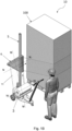
- a packaging machine which is the subject of the present invention, overall referred to as 10, in particular a machine intended to wrap one or more objects 100 of any nature and size, for example crates and/or packages and/or boxes and/or the like.
- the packaging machine 10 finds advantageous use in the sector of production and commercialization of automatic and/or semi-automatic machines.
- the packaging machine 10 which is the subject matter of the present invention insets itself in the sector of the packaging and wrapping machines, for wrapping, preferably by means of a tape of packaging material, objects of various nature such as those mentioned above.
- the tape of packaging material is preferably a flexible film made of polymeric material (e.g., HDPE and/or LDPE and/or similar), or paper, or any other material suitable for wrapping one or more objects and keeping them together during their transport.
- polymeric material e.g., HDPE and/or LDPE and/or similar
- paper or any other material suitable for wrapping one or more objects and keeping them together during their transport.
- the term 'packaging machine' is therefore to be intended, for the purposes of the present description, as any machine, apparatus or device, preferably automatic, suited to wrap a tape of flexible material around at least one object.
- the packaging machine 10 in particular intended to wrap one or more objects 100 with a tape 11 of packaging material, comprises a support structure 2.
- the support structure 2 is configured to house at least one reel 3 of tape 11 of packaging material.
- the support structure 2 defines a housing compartment 7, extending along an axis W, so as to contain at least partially the reel 3.
- the reel 3 is substantially cylindrical in shape, intended to be arranged along an axis substantially parallel to the axis W, and is configured to rotate about the aforementioned axis parallel to the axis W itself.
- the support structure 2 comprises at least two rollers 71, 72, and preferably four rollers 71, 72, 73 and 74, in particular in correspondence of the housing compartment 7, in particular intended to support the aforementioned reel 3.
- rollers 71, 72, 73 and 74 are substantially cylindrical in shape and rotatable around respective axes (not shown in the attached figures) that are substantially parallel to the axis W.
- said at least two rollers 71, 72 are configured to support the reel 3 and allow it to rotate around the axis W to unwind the tape 11.
- rollers 71, 72, 73 and 74 are idle rotatably mounted on the support structure 2 and rotate around their respective axes dragged by the rotation of the reel 3 during the unwinding of the tape 11.
- the support structure 2 is made of metal material, in particular of bent sheet metal, such as steel or similar. In this way, the support structure 2 is light and at the same time rigid and strong.
- the support structure 2 also includes handling means 4 configured to move the support structure 2 itself.
- the handling means 4 comprise wheels (and/or rollers and/or the like) 200 rotatably constrained to the support structure and configured to rest on the ground and to allow the machine 10 to move forward.
- the handling means 4 comprise at least one electric motor 41, (e.g., an asynchronous or brushless type motor), mechanically connected to at least one of the wheels 200, and in particular at least one front wheel.
- electric motor 41 e.g., an asynchronous or brushless type motor
- the handling means 4 comprise at least one reduction gear 42 (e.g., of the epicyclic or worm type) placed as a mechanical connection between the electric motor 41 and at least one of the wheels 200, configured to reduce the speed of the electric motor 41.
- the reduction gear is mounted on the support structure 2.
- the handling means further comprise a transmission member, for example a pinion (e.g. a toothed wheel or a pulley or any other transmission member known in itself to the person skilled in the art and therefore not further described) mechanically connected to the reduction gear 42 and configured to connect at least one of the wheels 200 to the reduction gear 42, to allow the packaging machine 10 to be moved on the ground and in particular around one or more objects 100 to be wrapped.
- a transmission member for example a pinion (e.g. a toothed wheel or a pulley or any other transmission member known in itself to the person skilled in the art and therefore not further described) mechanically connected to the reduction gear 42 and configured to connect at least one of the wheels 200 to the reduction gear 42, to allow the packaging machine 10 to be moved on the ground and in particular around one or more objects 100 to be wrapped.
- a transmission member for example a pinion (e.g. a toothed wheel or a pulley or any other transmission member known in itself to the person skilled in the art and therefore not further described)
- the packaging machine 10 further comprises at least one guiding member 5 mechanically connected to the support structure 2 and extending overhanging with respect to the support structure 2 along an axis Z.
- the axis Z of the guiding member 5 is substantially orthogonal with respect the axis W of the housing compartment 7 of the support structure 2. In this way, the unwinding of the tape 11 of packaging material from the reel 3 is simple and easy to perform.
- reel 3 unwinds by rotating around its horizontal axis W, facilitating the unwinding of the tape directly towards the deflecting means 6, as described in more detail below, making such unwinding simple and easy.
- the reel 3 has an orientation of its axis substantially parallel to the axis W, which makes the path of tape 11 short and direct since the number of changes of direction of the tape 11 itself is minimized.
- the packaging machine 10 also comprises deflecting means 6 configured to divert the tape 11 of packaging material.
- the deflecting means 6 are slidingly coupled to at least one guiding member 5.
- the sliding coupling between the deflecting means 6 and the guiding member 5 is of prismatic type.
- the deflecting means 6 comprise a sleeve 84 configured to mechanically couple with the guiding member 5, in particular the sleeve 84 is wrapped around the guiding member 5 and is susceptible to being moved slidingly along the axis Z.
- the sleeve 84 is essentially tubular in shape and is internally hollow to slidingly accommodate the guiding member 5.
- the guiding member 5 has a cross-section, made along a direction transverse to the axis Z, which is substantially constant along the axis Z itself and in particular substantially square or rectangular or circular.
- the sleeve 84 is made substantially to size with the guiding member 5, i.e., in other words it has a shape of its cross-section, made along a direction transverse to the axis Z, substantially square and/or rectangular and/or circular and preferably of the same shape as the section of the guiding member 5.
- the inner walls of the sleeve 84 comprise anti-friction elements, in particular skids 841 in polymeric material, in particular with low friction coefficient, for example polyethylene 1000 (PE 1000) and/or the like.
- skids 841 are mechanically mounted on the inner surfaces of the sleeve 84 and configured to reduce the friction generated by the sliding along the axis Z of the guiding member 5.
- the deflecting means 6 are movable between a proximal position in which the deflecting means 6 are moved closer to the support structure 2 and a distal position in which the deflecting means 6 are moved away from the support structure 2.
- the packaging machine 10 wraps one or more objects 100 with the tape 11 of packaging material, at least partially, along the axis Z.
- the deflecting means 6 are mechanically separated from the housing compartment 7.
- the deflecting means 6 are configured to receive the tape 11 along an unwinding direction M from the housing compartment 7 and to deviate the tape 11 along an exit direction N different with respect to the unwinding direction M, so that, in use, the exit direction N is directed towards one or more objects 100 to be wrapped.
- the unwinding direction of tape 11 is altered, and in particular directed towards one or more objects 100, allowing them to be wrapped requiring only one change of direction of tape 11.
- the deflecting means 6 comprise a frame 61, a first roller 62 rotatably mounted on the frame 61 and configured to rotate about an axis V substantially parallel to the axis W.
- the first roller 62 and the second roller 63 have a substantially cylindrical shape.
- the deflecting means 6 further comprise a second roller 63 rotatably mounted on the frame 61 and configured to rotate about an axis U substantially orthogonal to the axis W and substantially parallel to the axis Z of the guiding member 5.
- the sleeve 84 is mechanically constrained to the frame 61.
- the frame 61 comprises a first supporting arm 611 rotatably mounted the first roller 62 and extending transversely with respect to the axis Z and preferably substantially horizontally.
- the frame 61 comprises a second supporting arm 612 rotatably mounted the second roller 63 and extending parallel with respect to the axis Z and preferably substantially vertically.
- the first arm 611 and the second arm 612 are mechanically connected at their respective ends.
- the first roller 62 (and the first arm 611) can be arranged above or below the second roller 63 (and the second arm 612) without thereby falling outside the scope of protection of the present patent application.
- the deflecting means 6 can be arranged in such a way that the second roller 63 extends from an edge of the first roller 62, in particular upwards, or, in a further embodiment, downwards from the first roller 62, i.e. rotated by 180°.
- first and second rollers 62, 63 may be arranged in any suitable configuration to allow the tape 11 to be deflected and in particular its deflection towards the objects 100 to be wrapped.
- the tape 11 is deflected by the deflecting means 6, in particular by passing at least partially around the first roller 62 and the second roller 63, defining the exit direction N substantially orthogonal with respect to the axis Z.
- a surface of the same tape 11 exiting the deflecting means 6 is substantially parallel to the surface of one or more objects 100 to be wrapped.
- the tape 11 exiting reel 3 first winds and engages the first roller 62 maintaining the unwind direction M and then winds and engages the second roller 63 varying its direction, transverse to the unwind direction, defining the aforementioned exit direction N.
- the tape 11 is arranged with its orientation substantially parallel to a surface of one or more objects 100 to be wrapped.
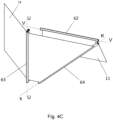
- the deflecting means 6 also comprise a third roller 64 rotatably mounted on the frame 61 and configured to rotate around an axis K.
- the axis K is inclined by a first angle ⁇ with respect to the axis V of the first roller 62 and by a second angle ⁇ ' with respect to the axis U of the second roller 63.
- the third roller 64 extends between two opposing ends, wherein a first end is rotatably constrained to the first arm 611 and a second end is rotatably constrained to the second arm 612. More specifically, the first end of the third roller 64 is rotatably constrained at a free end of the first arm 611 (opposite to the end constrained to the second arm 612) and the second end of the third roller 64 is rotatably constrained at a free end of the second arm 612 (opposite to the end constrained to the first arm 611).
- first roller 62, the second roller 63 and the third roller 64 are arranged on the frame 61 in such a way as to form a structure having essentially a triangular shape.
- the sum of the first angle ⁇ and the second angle ⁇ ' is equal to 90°.
- first angle ⁇ and the second angle ⁇ ' are substantially between 30° and 60°, in particular the first angle ⁇ and the second angle ⁇ ' are preferably substantially equal to 45°.
- the packaging machine 10 also comprises first actuating means 8 mechanically connected to the deflecting means 6 to move the latter along the axis Z of the guiding member 5.
- the packaging machine 10 further comprises at least one electronic control unit, electronically connected to the first actuating means 8 and configured to control the activation and/or operation of the first actuating means 8.
- the first actuating means 8 comprise at least one first motor 81 mechanically mounted on the support structure 2 and at least one transmission group 82 housed within said guiding member 5 and mechanically connected to said first motor 81 and said deflecting means 6.
- the transmission group 82 comprises at least one movable body 83 arranged at least partially parallel to the axis Z and mechanically constrained to the deflecting means 6 by at least one connecting element placed across the guiding member 5.
- the movable body 83 can be a chain or a belt.
- the guiding member 5 is equipped with a light 500 passing through and arranged parallel to the axis Z, crossed by the connecting element.
- the connecting element is arranged to cross the light 500 and is mechanically constrained on one side to the sleeve 84 of the deflecting means 6 and on the other side to the movable body 83 of the transmission group 82. In this way, with the movement of the movable body 83 coincides an equal movement of the deflecting means 6 along the guiding member 5.
- the transmission group 82 comprises at least one first rotating element 821, housed within the guiding member 5 at a first end of the guiding member 5 and rotatable about an axis T orthogonal to the axis Z.
- the transmission group 82 further preferably comprises at least one second rotating element 822, which is housed within the guiding member 5 at a second end of the guiding member 5 and rotatable about an axis S orthogonal to the axis Z.
- At least one of the first rotating element 821 and the second rotating element 822 is mechanically connected to the first motor 81.
- the movable body 83 is a flexible and elongated body, loop-wrapped at least partially around the first rotating element 821 and the second rotating element 822.
- the first rotating element 821 and the second rotating element 822 comprise a first pinion and a second pinion respectively.
- the movable element 83 is preferably a chain engaging the aforementioned first and second pinion.
- first rotating element 821 and the second rotating element 822 comprise a first pulley and a second pulley respectively.
- the movable element 83 is preferably a belt (which may be smooth, either trapezoidal or flat, or toothed) engaging the aforementioned first and second pulleys.
- the guiding member 5 in question is advantageously employable in a plurality of automatic and/or semi-automatic machines, such as in particular machines for packaging and wrapping objects of various types (e.g., crates, boxes, parcels, etc.).
- the guiding member which is the object of the invention, is employable in a packaging machine 10 of the type described above and also object of the present invention.
- the guiding member 5 in question can advantageously be used for the movement of at least one element along a prevailing movement direction, in particular rectilinear.
- a guiding member 5 intended to be mounted on a machine 10, in particular a packaging and/or wrapping machine, intended to slidingly mount deflecting means 6, for example for a tape 11 of packaging material.
- the guiding member 5 in question may, however, be advantageously mounted on any other type of automatic and/or semi-automatic machine for the handling of members of various types and intended for any other purpose or use without thereby falling outside the scope of protection of the present patent application.
- the guiding member 5 for a packaging machine 10 preferably intended to slidingly mount deflecting means 6 for a tape 11 of packaging material, has an elongated shape and extends along a prevailing axis Z.
- the guiding member 5 comprises at least a first longitudinal section 20.
- the guiding member 5 further comprises at least one second longitudinal section 30.
- the guiding member 5 further comprises articulation means 40 mechanically interposed between said first section 20 and said second section 30 and configured to move said first section 20 with respect to said second section 30 between a folded position, wherein said second section 30 is moved close to said first section 20, and an extended position, wherein said second section 30 is aligned with said first section 20 along said prevailing axis Z.
- the first longitudinal section 20 extends along a substantially rectilinear axis parallel to the prevailing axis Z of the guiding member 5.
- the first longitudinal section 20 is substantially tubular in shape and has a cross-section (i.e. a cross-section carried out along a direction orthogonal to the prevailing axis Z) having a substantially rectangular or square or circular shape.
- the first longitudinal section 20 is internally hollow.
- the first longitudinal section 20 defines internally a housing volume suitable for accommodating suitable transmission members 82, for example pinions, belts or chains, for the movement of, for example, the aforementioned deflecting means 6 sliding along the axis Z of the guiding member 5 (as described in more detail below).
- suitable transmission members 82 for example pinions, belts or chains
- the first longitudinal section 20 is made of metallic material, for example preferably steel or similar.
- the second longitudinal section 30 is tubular in shape and has a cross-section (i.e. carried out along a direction orthogonal to the prevailing axis Z) having a substantially rectangular or square or circular shape.
- the shape of the tubular cross-section of the first section 20 is preferably square.
- first section 20 and the second section 30 have the same shape and preferably the same external dimensions.
- the second longitudinal section 30 defines internally a housing volume suitable for housing the aforementioned transmission members, for example pinions, belts or chains, suitable for the movement of, for example, deflecting means 6 sliding along the axis Z of the guiding member 5 (as described in more detail below).
- the aforementioned transmission members for example pinions, belts or chains
- the second longitudinal section 30 is made of metal material, for example preferably steel or similar.
- the first longitudinal section 20 comprises at least one first coupling portion 50 and the second longitudinal section 30 comprises at least one second coupling portion 60.
- the articulation means 40 are rotatably connected to the first coupling portion 50 and the second coupling portion 60.
- the first section 20 and the second section 30 can rotate and be arranged in the above-mentioned folded configuration.
- This configuration allows to reduce the space occupied by the guiding member 5 with respect to its longitudinal extension.
- the guiding member 5 can be moved and transported easily and quickly, for example it can be accommodated in a shipping crate or parcel, particularly on standard-sized pallets.
- the articulation means 40 are connected to the first coupling portion 50 and the second coupling portion 60 by at least two corresponding rotoidal couplings, for example pins 45 preferably cylindrical and, preferably, made of metallic material, e.g. steel or the like.
- the articulation means 40 comprise at least one longitudinal intermediate section 80, interposed between said first section 20 and said second section 30 and configured to distance said first coupling portion 50 and said second coupling portion 60.
- the intermediate longitudinal section 80 comprises a third 110 coupling portion and a fourth 120 coupling portion.
- the third coupling portion 110 is rotatably coupled with the first coupling portion 50 of the first longitudinal section 20 and the fourth coupling portion 120 is rotatably coupled with the second coupling portion 60 of the second longitudinal section 30.
- cylindrical pins 45 mechanically connect the first coupling portion 50 of the first section 20 to the third coupling portion 110 of the intermediate section 80, and also connect the second coupling portion 60 of the second section 30 to the fourth coupling portion 120 of the intermediate section 80.
- the pins 45 mechanically connect the above-mentioned portions by means of threaded elements 451, for example screws, in particular preferably hexagon socket countersunk head screws. In this way, there are no protruding portions that can cause impacts and/or collisions with surrounding portions of the guiding member 5.
- the first section 20 and the second section 30, by means of the at least two rotoidal couplings, can rotate relative to each other by an angle of about 180° in both directions of rotation.
- the first section 20 may rotate relative to the intermediate section 80 by an angle of about 90° in both directions of rotation.
- the second section 30 may rotate relative to the intermediate section 80 by an angle of about 90° in both directions of rotation.
- the guiding member 5 further comprises blocking means 70 configured to be mechanically coupled to the articulation means 40.
- blocking means 70 configured to be mechanically coupled to the articulation means 40.
- the blocking means 70 are coupled to the articulation means 40, the guiding member 5 is in an extended configuration. Otherwise, when the blocking means 70 are not coupled to the articulation means 40, the first section 20 and the second section 30 are free to rotate around the pins 45 in such a way as to allow the guiding member 5 to assume the aforementioned folded configuration.
- the blocking means 70 comprise at least two covering elements 90', 90" accommodated to size between the first longitudinal section 20 and the second longitudinal section 30 to define the substantially continuous outer surface.
- the cover elements 90', 90" are mechanically connected by means of threaded elements, in particular screws, preferably hexagon socket countersunk screws.
- the covering elements 90', 90" are symmetrical to each other and shaped in a basically "C"-shape.
- the covering elements 90', 90" are made of metal material, in particular steel or similar.
- the covering elements 90', 90" of the blocking means 70 comprise at least two plates and preferably at least four plates, in accordance with the preferred embodiment shown in the attached figures.
- the at least four plates have a bent shape and are preferably made of metal material, in particular steel.
- the at least four plates cover at least partially the first coupling portion 50 and the second coupling portion 60.
- the at least four plates are symmetrical with respect to the axis Z and are mechanically coupled through fastening means 701, for example threaded elements, in particular screws, preferably hexagon socket countersunk screws.
- the head of the screws does not protrude, along a direction orthogonal to the axis Z, beyond the external profile of the guiding member 5 in the extended configuration.
- the screw head once screwed in, does not obstruct the movement of the deflecting means 6 preferably coupled to the guiding member 5.
- the blocking means 70 can be mechanically coupled in a removable manner between the first section 20 and the second section 30 and can be configured to block the articulation means 40 in such a way that the first section 20 and the second section 30 are in an extended position.
- the blocking means 70 can be mechanically decoupled to release the articulation means 40 in such a way that the first section 20 is movable with respect to the second section 30 to reach the folded position.
- the intermediate section 80 allows a greater movement amplitude than the first section 20 and the second section 30.
- the guiding member 5 can be folded, in particular a rotation of the first longitudinal section 20 with respect to the first coupling portion 50 and of the second longitudinal section 30 with respect to the second coupling portion 60. Such movements allow the guiding member 5 to assume a folded configuration, thereby resulting to be compact and space-saving.
- the blocking means 70 are configured to cover, at least partially, the articulation means 40 in a extending position.
- the outer surface of the guiding member 5 is continuous. Therefore, there are no discontinuities along the axis Z of the guiding member 5 which may cause obstructions and hinder the movement of the deflecting means 6.
- the blocking means 70 together with the first section 20 and the second section 30 in an extended configuration define a substantially continuous outer surface.
- the deflecting means 6 can slide along the axis Z of the guiding member 5 without encountering obstacles.
- the at least one intermediate section 80 extends along the axis Z by a length equal to at least twice the extension along the axis Z of the first coupling portion 50 and/or the second coupling portion 60.
- first longitudinal section 20 and the second longitudinal section 30 can rotate with respect to their respective coupling portions by an angle of approximately 180° without impacts.
- the guiding member is particularly advantageous because:
Landscapes
- Engineering & Computer Science (AREA)
- Mechanical Engineering (AREA)
- Basic Packing Technique (AREA)
Abstract
Description
- The present invention relates to a guiding member, preferably a guiding member intended to be mechanically mounted on a machine, in particular a packaging machine, whether it is automatic or semi-automatic, according to the preamble of
independent claim 1. - In more detail, the guiding member in question is intended to be slidingly traversed by at least one element, for example a skid and/or trolley and/or the like and is advantageously used in the field of production and commercialization of structures and/or machines, in particular in the field of systems and apparatuses for handling members of various types.
- Therefore, the guiding member finds advantageous use in the field of production and commercialization of systems and apparatuses for handling, in particular guiding member intended to be mounted on packaging machines and intended to move elements and/or groups connected thereto in a sliding manner (e.g., mechanical assemblies such as welding units, packaging, wrapping and winding groups, etc.).
- It is well known in the relevant technical field that guiding members are used for the movement of elements of various types, for example, units and/or groups of automatic and/or semiautomatic machines, particularly in packaging, wrapping and winding machines.
- In more detail, guiding members of known type typically comprise an elongated body extending along a predominantly substantially rectilinear direction of development.
- Specifically, the body carries slidingly mounted an element to be moved, e.g., by means of a prism-type coupling (e.g., skid-rail and/or rail and/or the like). In this way, the element can slide along the direction of development of the body, e.g., by making an alternative type of movement.
- In more detail, the movement of the element, along the direction of development of the body, typically makes sliding friction between the element to be moved and the elongated body. To make the handling smooth, the known type members normally comprise anti-friction components (e.g., prismatic skids made of PE and/or similar materials), for example, by placing such components between the contact surfaces of the elongated body and the sliding element connected thereto. Otherwise, the same movement between the elongated body and the element can take place by means of rolling friction, e.g., by the use of rollers, casters and the like, placed between the surfaces of the body and the element.
- Typically, guiding members of known types reach in practice extensions of even more than 2-2.5 meters in length, particularly when mounted in machines that have to perform large movements (i.e., very long strokes by the sliding elements along the guiding members' body). This makes the guiding member heavy and cumbersome.
- The guiding member of known types briefly described so far have proved in practice not without drawbacks.
- The main drawback lies in the fact that guiding members of known types are cumbersome. Such members, particularly when they reach extensions of more than 2 meters in length, make handling and maintenance operations difficult and complex, for example, within a manufacturing plant.
- A further drawback lies in the fact that the guiding members of known type, due to their large extension, are difficult to transport, e.g., for their sale.
- In fact, such guiding members require very bulky and cumbersome packaging. In addition, the guiding members of known type cannot fit into the traditional standard crates and/or boxes used for shipping and transport (e.g., on trucks or the like), nor can they be placed on standard pallets, i.e., euro-pallets.
- A further drawback lies in the fact that the known type guiding members do not allow, for an operator, any quick and easy access to transmission member (e.g., chain and pinions) accommodated in the housing volume of the body.
- A further drawback lies in the fact that guiding members of known type do not allow them to be mechanically disassembled in a rapid and easy manner, such as for repair or replacement of the transmission means (i.e., drive chain and pinions) housed inside the body.
- A further drawback lies in the fact that the guiding members of known type do not allow for disassembly of the aforementioned transmission members, making these members inflexible.
- It is a purpose of the present invention to provide a guiding member that allows to obviate and remedy, at least in part, the drawbacks of the above-mentioned known technique.
- Further purpose of the present invention is to provide a guiding member that is compact and space-saving.
- Further purpose of the present invention is to provide a guiding member that is easily transportable, particularly one that can be housed on standard-sized transport pallets.
- Further purpose of the present invention is to provide a guiding member that is easy to assemble and/or disassemble on/from a machine, in particular a packaging and winding machine.
- Further purpose of the present invention is to provide a guiding member that is applicable to machines, for example automatic and/or semi-automatic machines, such as more particularly packaging and winding machines, that are commonly commercially available without the need for complex and costly modifications.
- Further purpose of the present invention is to provide a guiding member that is cost-effective.
- Further purpose of the present invention is to provide a guiding member that is implementable in a simple and rapid manner and with low cost.
- Further purpose of the present invention is to provide a guiding member that is applicable easily, quickly, and with low cost.
- All of the purposes, either singly or in any combination thereof, and others that will result from the following detailed description are achieved, according to the invention, by a guiding
member 5 having the characteristics set forth inindependent claim 1. - In particular, the aforementioned purposes are achieved by a guiding
member 5 for a packaging machine, preferably intended for slidingly mounting deflecting means for a tape of packaging material, having an elongated shape and extending along a prevailing axis Z; comprising at least a firstlongitudinal section 20; at least a secondlongitudinal section 30; articulation means 40 mechanically interposed between saidfirst section 20 and saidsecond section 30 and configured to move saidfirst section 20 with respect to saidsecond section 30 between a folded position, wherein saidsecond section 30 is moved closer to saidfirst section 20 and an extended position, wherein saidsecond section 30 is aligned with saidfirst section 20 along said prevailing axis Z. - Advantageously, said at least one first
longitudinal section 20 comprises at least onefirst coupling portion 50 and said secondlongitudinal section 30 comprises at least onesecond coupling portion 60; said articulation means 40 being rotatably connected to saidfirst coupling portion 50 and to saidsecond coupling portion 60. - Advantageously, the guiding
member 5 includesblocking means 70 configured to be mechanically coupled with said articulation means 40, with saidfirst section 20 and saidsecond section 30 in said extended position. - Advantageously, said
blocking means 70 are mechanically coupled in a removable manner between saidfirst section 20 and saidsecond section 30 and configured to block said articulation means 40 in such a way that saidfirst section 20 and saidsecond section 30 are in said extended position, - and said
blocking means 70 are mechanically decoupled to release said articulation means 40 in such a way that saidfirst section 20 is movable with respect to saidsecond section 30 to reach said folded position. - Advantageously, said articulation means 40 comprise at least one longitudinal
intermediate section 80 interposed between saidfirst section 20 and saidsecond section 30 and configured to distance saidfirst coupling portion 50 and saidsecond coupling portion 60. - Advantageously, said longitudinal
intermediate section 80 comprises athird coupling portion 110 and afourth coupling portion 120; saidthird coupling portion 110 being rotatably coupled with saidfirst coupling portion 50 of said firstlongitudinal section 20 and saidfourth coupling portion 120 being rotatably coupled with saidsecond coupling portion 60 of said secondlongitudinal section 30. - Advantageously, said
blocking means 70 are configured to cover, at least partially, said articulation means 40 in said extended position. - Advantageously, said blocking means 70 together with said
first section 20 and saidsecond section 30 in said extended configuration define a substantially continuous outer surface. - Advantageously, said blocking means 70 comprise at least two cover elements 90', 90' accommodated to size between said first
longitudinal section 20 and said secondlongitudinal section 30 to define said substantially continuous outer surface. - Advantageously, said at least one
intermediate section 80 extends along said axis Z for a length equal to at least twice the extension along said axis Z of saidfirst coupling portion 50 and/or saidsecond coupling portion 60. - The present invention is herein further elucidated in some of its preferred forms of practical embodiment, set forth for illustrative and non-limiting purposes only, with reference to the attached drawings, wherein:
-
Figure 1A shows a perspective view of a packaging machine object of the present invention, in particular, it is shown in use, side by side with objects to be packed; -
Figure 1B shows a further perspective view of the machine illustrated infigure 1A ; -
Figure 2 shows a perspective view of the machine illustrated infigure 1A , with some parts removed to better highlight others; -
Figure 3 shows a perspective view of a detail of the machine according to the invention, concerning deflecting means; -
Figures 4A, 4B show further detailed perspective views of the deflecting means illustrated infigure 3 , engaged by a tape of packaging material; -
Figure 4C shows a perspective view of the deflecting means illustrated infigures 4A and 4B with some parts removed to better highlight others; -
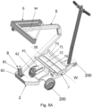
Figure 5A shows a perspective view of the packaging machine with a guiding member arranged in a partially folded configuration; -
Figure 5B shows a further perspective view of the packaging machine illustrated infigure 5A ; -
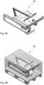
Figure 6A shows a perspective view of the packaging machine in a folded configuration; -
Figure 6B shows a further perspective view of the packaging machine illustrated infigure 6A , placed on a pallet and inside a box for its transport; -
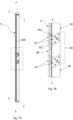
Figure 7A shows a perspective view of the guiding member, which is also object of the present invention; -
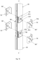
Figure 7B shows a perspective view of a detail of the guiding member illustrated infigure 7A ; -
Figure 7C shows an exploded perspective view of the guiding member's detail shown infigure 7B ; -
Figure 8A shows a perspective view of the guiding member's detail illustrated inFigures 7B and7C in its partially folded configuration; -
Figure 8B shows a further perspective view of guiding member's detail illustrated infigure 8A in its folded configuration; -
Figure 9A shows a longitudinal sectional view of the guiding member illustrated infigure 7A ; -
Figure 9B shows a longitudinal sectional view of guiding member's detail illustrated infigure 9A ; -
Figure 9C shows a further longitudinal sectional view of a further detail of the guiding member illustrated infigure 9A . - With reference to the attached figures, a packaging machine, which is the subject of the present invention, overall referred to as 10, in particular a machine intended to wrap one or
more objects 100 of any nature and size, for example crates and/or packages and/or boxes and/or the like. - The
packaging machine 10 according to the invention finds advantageous use in the sector of production and commercialization of automatic and/or semi-automatic machines. In particular, thepackaging machine 10, which is the subject matter of the present invention insets itself in the sector of the packaging and wrapping machines, for wrapping, preferably by means of a tape of packaging material, objects of various nature such as those mentioned above. - More in detail, the tape of packaging material is preferably a flexible film made of polymeric material (e.g., HDPE and/or LDPE and/or similar), or paper, or any other material suitable for wrapping one or more objects and keeping them together during their transport.
- The term 'packaging machine' is therefore to be intended, for the purposes of the present description, as any machine, apparatus or device, preferably automatic, suited to wrap a tape of flexible material around at least one object.
- The
packaging machine 10, in particular intended to wrap one ormore objects 100 with atape 11 of packaging material, comprises asupport structure 2. - More in detail, the
support structure 2 is configured to house at least onereel 3 oftape 11 of packaging material. - More in detail, the
support structure 2 defines ahousing compartment 7, extending along an axis W, so as to contain at least partially thereel 3. - Preferably, the
reel 3 is substantially cylindrical in shape, intended to be arranged along an axis substantially parallel to the axis W, and is configured to rotate about the aforementioned axis parallel to the axis W itself. - Preferably, the
support structure 2 comprises at least tworollers rollers housing compartment 7, in particular intended to support theaforementioned reel 3. - Advantageously, the
rollers - In particular, said at least two
rollers reel 3 and allow it to rotate around the axis W to unwind thetape 11. - More in detail, the
rollers support structure 2 and rotate around their respective axes dragged by the rotation of thereel 3 during the unwinding of thetape 11. - Preferably, the
support structure 2 is made of metal material, in particular of bent sheet metal, such as steel or similar. In this way, thesupport structure 2 is light and at the same time rigid and strong. - The
support structure 2 also includes handling means 4 configured to move thesupport structure 2 itself. - Preferably, the handling means 4 comprise wheels (and/or rollers and/or the like) 200 rotatably constrained to the support structure and configured to rest on the ground and to allow the
machine 10 to move forward. - Conveniently, the handling means 4 comprise at least one
electric motor 41, (e.g., an asynchronous or brushless type motor), mechanically connected to at least one of thewheels 200, and in particular at least one front wheel. - Preferably, the handling means 4 comprise at least one reduction gear 42 (e.g., of the epicyclic or worm type) placed as a mechanical connection between the
electric motor 41 and at least one of thewheels 200, configured to reduce the speed of theelectric motor 41. Preferably, the reduction gear is mounted on thesupport structure 2. - Preferably, the handling means further comprise a transmission member, for example a pinion (e.g. a toothed wheel or a pulley or any other transmission member known in itself to the person skilled in the art and therefore not further described) mechanically connected to the
reduction gear 42 and configured to connect at least one of thewheels 200 to thereduction gear 42, to allow thepackaging machine 10 to be moved on the ground and in particular around one ormore objects 100 to be wrapped. - The
packaging machine 10 further comprises at least one guidingmember 5 mechanically connected to thesupport structure 2 and extending overhanging with respect to thesupport structure 2 along an axis Z. - More in detail, the axis Z of the guiding
member 5 is substantially orthogonal with respect the axis W of thehousing compartment 7 of thesupport structure 2. In this way, the unwinding of thetape 11 of packaging material from thereel 3 is simple and easy to perform. - In fact,
reel 3 unwinds by rotating around its horizontal axis W, facilitating the unwinding of the tape directly towards the deflecting means 6, as described in more detail below, making such unwinding simple and easy. - In particular, the
reel 3 has an orientation of its axis substantially parallel to the axis W, which makes the path oftape 11 short and direct since the number of changes of direction of thetape 11 itself is minimized. - The
packaging machine 10 also comprises deflecting means 6 configured to divert thetape 11 of packaging material. - More in detail, the deflecting means 6 are slidingly coupled to at least one guiding
member 5. - Preferably, the sliding coupling between the deflecting means 6 and the guiding
member 5 is of prismatic type. - In particular, the deflecting means 6 comprise a
sleeve 84 configured to mechanically couple with the guidingmember 5, in particular thesleeve 84 is wrapped around the guidingmember 5 and is susceptible to being moved slidingly along the axis Z. - More in detail, the
sleeve 84 is essentially tubular in shape and is internally hollow to slidingly accommodate the guidingmember 5. - Preferably, the guiding
member 5 has a cross-section, made along a direction transverse to the axis Z, which is substantially constant along the axis Z itself and in particular substantially square or rectangular or circular. - Preferably, the
sleeve 84 is made substantially to size with the guidingmember 5, i.e., in other words it has a shape of its cross-section, made along a direction transverse to the axis Z, substantially square and/or rectangular and/or circular and preferably of the same shape as the section of the guidingmember 5. - Preferably, the inner walls of the
sleeve 84 comprise anti-friction elements, inparticular skids 841 in polymeric material, in particular with low friction coefficient, for example polyethylene 1000 (PE 1000) and/or the like. In particular,such skids 841 are mechanically mounted on the inner surfaces of thesleeve 84 and configured to reduce the friction generated by the sliding along the axis Z of the guidingmember 5. - More in detail, the deflecting means 6 are movable between a proximal position in which the deflecting means 6 are moved closer to the
support structure 2 and a distal position in which the deflecting means 6 are moved away from thesupport structure 2. - In this way, the
packaging machine 10 wraps one ormore objects 100 with thetape 11 of packaging material, at least partially, along the axis Z. - Advantageously, the deflecting means 6 are mechanically separated from the
housing compartment 7. - In this way, the movement of the deflecting means 6 along the axis Z of the guiding
member 5 is simple and quick as this provision obviates the drawbacks of the known technique by not requiring the movement of thereel 3 with respect to thesupport structure 2. - More specifically, the deflecting means 6 are configured to receive the
tape 11 along an unwinding direction M from thehousing compartment 7 and to deviate thetape 11 along an exit direction N different with respect to the unwinding direction M, so that, in use, the exit direction N is directed towards one ormore objects 100 to be wrapped. - In this way, the unwinding direction of
tape 11 is altered, and in particular directed towards one ormore objects 100, allowing them to be wrapped requiring only one change of direction oftape 11. - More in detail, the deflecting means 6 comprise a
frame 61, afirst roller 62 rotatably mounted on theframe 61 and configured to rotate about an axis V substantially parallel to the axis W. Preferably, thefirst roller 62 and thesecond roller 63 have a substantially cylindrical shape. - The deflecting means 6 further comprise a
second roller 63 rotatably mounted on theframe 61 and configured to rotate about an axis U substantially orthogonal to the axis W and substantially parallel to the axis Z of the guidingmember 5. - Conveniently, the
sleeve 84 is mechanically constrained to theframe 61. - Preferably, the
frame 61 comprises a first supporting arm 611 rotatably mounted thefirst roller 62 and extending transversely with respect to the axis Z and preferably substantially horizontally. - Furthermore, preferably, the
frame 61 comprises a second supporting arm 612 rotatably mounted thesecond roller 63 and extending parallel with respect to the axis Z and preferably substantially vertically. Conveniently, in accordance with the preferred embodiment illustrated in the attached figures, the first arm 611 and the second arm 612 are mechanically connected at their respective ends. - The first roller 62 (and the first arm 611) can be arranged above or below the second roller 63 (and the second arm 612) without thereby falling outside the scope of protection of the present patent application.
- In other words, the deflecting means 6 can be arranged in such a way that the
second roller 63 extends from an edge of thefirst roller 62, in particular upwards, or, in a further embodiment, downwards from thefirst roller 62, i.e. rotated by 180°. - Furthermore, the first and
second rollers tape 11 to be deflected and in particular its deflection towards theobjects 100 to be wrapped. - Preferably, the
tape 11 is deflected by the deflecting means 6, in particular by passing at least partially around thefirst roller 62 and thesecond roller 63, defining the exit direction N substantially orthogonal with respect to the axis Z. In this way, a surface of thesame tape 11 exiting the deflecting means 6 is substantially parallel to the surface of one ormore objects 100 to be wrapped. - Operatively, the
tape 11 exitingreel 3 first winds and engages thefirst roller 62 maintaining the unwind direction M and then winds and engages thesecond roller 63 varying its direction, transverse to the unwind direction, defining the aforementioned exit direction N. - In this way, the
tape 11 is arranged with its orientation substantially parallel to a surface of one ormore objects 100 to be wrapped. - More specifically, the deflecting means 6 also comprise a
third roller 64 rotatably mounted on theframe 61 and configured to rotate around an axis K. - In particular, the axis K is inclined by a first angle θ with respect to the axis V of the
first roller 62 and by a second angle θ' with respect to the axis U of thesecond roller 63. - Preferably, the
third roller 64 extends between two opposing ends, wherein a first end is rotatably constrained to the first arm 611 and a second end is rotatably constrained to the second arm 612. More specifically, the first end of thethird roller 64 is rotatably constrained at a free end of the first arm 611 (opposite to the end constrained to the second arm 612) and the second end of thethird roller 64 is rotatably constrained at a free end of the second arm 612 (opposite to the end constrained to the first arm 611). - In other words, the
first roller 62, thesecond roller 63 and thethird roller 64 are arranged on theframe 61 in such a way as to form a structure having essentially a triangular shape. - Preferably, the sum of the first angle θ and the second angle θ' is equal to 90°.
- Preferably, the first angle θ and the second angle θ' are substantially between 30° and 60°, in particular the first angle θ and the second angle θ' are preferably substantially equal to 45°.
- The
packaging machine 10 also comprises first actuating means 8 mechanically connected to the deflecting means 6 to move the latter along the axis Z of the guidingmember 5. - The
packaging machine 10 further comprises at least one electronic control unit, electronically connected to the first actuating means 8 and configured to control the activation and/or operation of the first actuating means 8. - More in detail, the first actuating means 8 comprise at least one
first motor 81 mechanically mounted on thesupport structure 2 and at least onetransmission group 82 housed within said guidingmember 5 and mechanically connected to saidfirst motor 81 and said deflecting means 6. - In more detail, the
transmission group 82 comprises at least one movable body 83 arranged at least partially parallel to the axis Z and mechanically constrained to the deflecting means 6 by at least one connecting element placed across the guidingmember 5. - Preferably, the movable body 83 can be a chain or a belt.
- Preferably, the guiding
member 5 is equipped with a light 500 passing through and arranged parallel to the axis Z, crossed by the connecting element. - More in detail, the connecting element is arranged to cross the light 500 and is mechanically constrained on one side to the
sleeve 84 of the deflecting means 6 and on the other side to the movable body 83 of thetransmission group 82. In this way, with the movement of the movable body 83 coincides an equal movement of the deflecting means 6 along the guidingmember 5. - In more detail, the
transmission group 82 comprises at least one firstrotating element 821, housed within the guidingmember 5 at a first end of the guidingmember 5 and rotatable about an axis T orthogonal to the axis Z. - The
transmission group 82 further preferably comprises at least one secondrotating element 822, which is housed within the guidingmember 5 at a second end of the guidingmember 5 and rotatable about an axis S orthogonal to the axis Z. - In particular, at least one of the first
rotating element 821 and the secondrotating element 822 is mechanically connected to thefirst motor 81. - In more detail, the movable body 83 is a flexible and elongated body, loop-wrapped at least partially around the first
rotating element 821 and the secondrotating element 822. - Preferably, the first
rotating element 821 and the secondrotating element 822 comprise a first pinion and a second pinion respectively. In this case, the movable element 83 is preferably a chain engaging the aforementioned first and second pinion. - Otherwise, the first
rotating element 821 and the secondrotating element 822 comprise a first pulley and a second pulley respectively. In this case, the movable element 83 is preferably a belt (which may be smooth, either trapezoidal or flat, or toothed) engaging the aforementioned first and second pulleys. - It is also an object of the present invention to provide a guiding
member 5 for apackaging machine 10, preferably of the type described above, and of which the same numerical references will be retained for simplicity of exposition. - As mentioned above, the guiding
member 5 in question is advantageously employable in a plurality of automatic and/or semi-automatic machines, such as in particular machines for packaging and wrapping objects of various types (e.g., crates, boxes, parcels, etc.). Preferably, the guiding member, which is the object of the invention, is employable in apackaging machine 10 of the type described above and also object of the present invention. - Obviously, all of the features described with reference to the
packaging machine 10, taken alone or in any combination thereof, should also be understood to be described with reference to the guidingmember 5, which is also an object of the present invention. - Conveniently, the guiding
member 5 in question can advantageously be used for the movement of at least one element along a prevailing movement direction, in particular rectilinear. - In the following, specific reference will be made to a guiding
member 5 intended to be mounted on amachine 10, in particular a packaging and/or wrapping machine, intended to slidingly mount deflecting means 6, for example for atape 11 of packaging material. - Obviously, the guiding
member 5 in question may, however, be advantageously mounted on any other type of automatic and/or semi-automatic machine for the handling of members of various types and intended for any other purpose or use without thereby falling outside the scope of protection of the present patent application. - The guiding
member 5 for apackaging machine 10, preferably intended to slidingly mount deflecting means 6 for atape 11 of packaging material, has an elongated shape and extends along a prevailing axis Z. - The guiding
member 5 comprises at least a firstlongitudinal section 20. The guidingmember 5 further comprises at least one secondlongitudinal section 30. The guidingmember 5 further comprises articulation means 40 mechanically interposed between saidfirst section 20 and saidsecond section 30 and configured to move saidfirst section 20 with respect to saidsecond section 30 between a folded position, wherein saidsecond section 30 is moved close to saidfirst section 20, and an extended position, wherein saidsecond section 30 is aligned with saidfirst section 20 along said prevailing axis Z. - Preferably, according to the aforementioned extended configuration illustrated in the attached
figure 1 , the firstlongitudinal section 20 extends along a substantially rectilinear axis parallel to the prevailing axis Z of the guidingmember 5. - Preferably, the first
longitudinal section 20 is substantially tubular in shape and has a cross-section (i.e. a cross-section carried out along a direction orthogonal to the prevailing axis Z) having a substantially rectangular or square or circular shape. Preferably, the firstlongitudinal section 20 is internally hollow. - In this way, the first
longitudinal section 20 defines internally a housing volume suitable for accommodatingsuitable transmission members 82, for example pinions, belts or chains, for the movement of, for example, the aforementioned deflecting means 6 sliding along the axis Z of the guiding member 5 (as described in more detail below). - Preferably, the first
longitudinal section 20 is made of metallic material, for example preferably steel or similar. - Preferably, the second
longitudinal section 30 is tubular in shape and has a cross-section (i.e. carried out along a direction orthogonal to the prevailing axis Z) having a substantially rectangular or square or circular shape. The shape of the tubular cross-section of thefirst section 20 is preferably square. - Advantageously, the
first section 20 and thesecond section 30 have the same shape and preferably the same external dimensions. - In this way, the second
longitudinal section 30 defines internally a housing volume suitable for housing the aforementioned transmission members, for example pinions, belts or chains, suitable for the movement of, for example, deflecting means 6 sliding along the axis Z of the guiding member 5 (as described in more detail below). - Preferably, the second
longitudinal section 30 is made of metal material, for example preferably steel or similar. - Advantageously, the first
longitudinal section 20 comprises at least onefirst coupling portion 50 and the secondlongitudinal section 30 comprises at least onesecond coupling portion 60. Further, the articulation means 40 are rotatably connected to thefirst coupling portion 50 and thesecond coupling portion 60. - In this way, the
first section 20 and thesecond section 30 can rotate and be arranged in the above-mentioned folded configuration. This configuration allows to reduce the space occupied by the guidingmember 5 with respect to its longitudinal extension. Advantageously, the guidingmember 5 can be moved and transported easily and quickly, for example it can be accommodated in a shipping crate or parcel, particularly on standard-sized pallets. - Preferably, the articulation means 40 are connected to the
first coupling portion 50 and thesecond coupling portion 60 by at least two corresponding rotoidal couplings, for example pins 45 preferably cylindrical and, preferably, made of metallic material, e.g. steel or the like. - Advantageously, the articulation means 40 comprise at least one longitudinal
intermediate section 80, interposed between saidfirst section 20 and saidsecond section 30 and configured to distance saidfirst coupling portion 50 and saidsecond coupling portion 60. - Advantageously, the intermediate
longitudinal section 80 comprises a third 110 coupling portion and a fourth 120 coupling portion. - More in detail, the
third coupling portion 110 is rotatably coupled with thefirst coupling portion 50 of the firstlongitudinal section 20 and thefourth coupling portion 120 is rotatably coupled with thesecond coupling portion 60 of the secondlongitudinal section 30. - More in detail,
cylindrical pins 45 mechanically connect thefirst coupling portion 50 of thefirst section 20 to thethird coupling portion 110 of theintermediate section 80, and also connect thesecond coupling portion 60 of thesecond section 30 to thefourth coupling portion 120 of theintermediate section 80. - In particular, the
pins 45 mechanically connect the above-mentioned portions by means of threadedelements 451, for example screws, in particular preferably hexagon socket countersunk head screws. In this way, there are no protruding portions that can cause impacts and/or collisions with surrounding portions of the guidingmember 5. - In this way, the rotation of the
first section 20 and thesecond section 30 is quick and easy. - Preferably, the
first section 20 and thesecond section 30, by means of the at least two rotoidal couplings, can rotate relative to each other by an angle of about 180° in both directions of rotation. - Preferably, the
first section 20 may rotate relative to theintermediate section 80 by an angle of about 90° in both directions of rotation. Similarly, preferably, thesecond section 30 may rotate relative to theintermediate section 80 by an angle of about 90° in both directions of rotation. - Advantageously, the guiding
member 5 further comprises blocking means 70 configured to be mechanically coupled to the articulation means 40. In particular, with thefirst section 20 and thesecond section 30 in an extended position. - In this way, when the blocking means 70 are coupled to the articulation means 40, the guiding
member 5 is in an extended configuration. Otherwise, when the blocking means 70 are not coupled to the articulation means 40, thefirst section 20 and thesecond section 30 are free to rotate around thepins 45 in such a way as to allow the guidingmember 5 to assume the aforementioned folded configuration. - Advantageously, the blocking means 70 comprise at least two covering
elements 90', 90" accommodated to size between the firstlongitudinal section 20 and the secondlongitudinal section 30 to define the substantially continuous outer surface. - Preferably, the
cover elements 90', 90" are mechanically connected by means of threaded elements, in particular screws, preferably hexagon socket countersunk screws. - In this way, there are no protruding portions from the outer surface of the guiding
member 5. - Preferably, the covering
elements 90', 90" are symmetrical to each other and shaped in a basically "C"-shape. - Preferably, the covering
elements 90', 90" are made of metal material, in particular steel or similar. - Preferably, the covering
elements 90', 90" of the blocking means 70 comprise at least two plates and preferably at least four plates, in accordance with the preferred embodiment shown in the attached figures. The at least four plates have a bent shape and are preferably made of metal material, in particular steel. - Preferably the at least four plates, with the guiding
member 5 in the extended configuration, cover at least partially thefirst coupling portion 50 and thesecond coupling portion 60. - Preferably, the at least four plates are symmetrical with respect to the axis Z and are mechanically coupled through fastening means 701, for example threaded elements, in particular screws, preferably hexagon socket countersunk screws.
- In this way, the head of the screws does not protrude, along a direction orthogonal to the axis Z, beyond the external profile of the guiding
member 5 in the extended configuration. In other words, the screw head, once screwed in, does not obstruct the movement of the deflecting means 6 preferably coupled to the guidingmember 5. - Advantageously, the blocking means 70 can be mechanically coupled in a removable manner between the
first section 20 and thesecond section 30 and can be configured to block the articulation means 40 in such a way that thefirst section 20 and thesecond section 30 are in an extended position. - Furthermore, the blocking means 70 can be mechanically decoupled to release the articulation means 40 in such a way that the
first section 20 is movable with respect to thesecond section 30 to reach the folded position. - In this way, the
intermediate section 80 allows a greater movement amplitude than thefirst section 20 and thesecond section 30. - In this way, the guiding
member 5 can be folded, in particular a rotation of the firstlongitudinal section 20 with respect to thefirst coupling portion 50 and of the secondlongitudinal section 30 with respect to thesecond coupling portion 60. Such movements allow the guidingmember 5 to assume a folded configuration, thereby resulting to be compact and space-saving. - Advantageously, the blocking means 70 are configured to cover, at least partially, the articulation means 40 in a extending position.
- In this way, the outer surface of the guiding
member 5 is continuous. Therefore, there are no discontinuities along the axis Z of the guidingmember 5 which may cause obstructions and hinder the movement of the deflecting means 6. - More in detail, the blocking means 70 together with the
first section 20 and thesecond section 30 in an extended configuration define a substantially continuous outer surface. - In this way, the deflecting means 6 can slide along the axis Z of the guiding
member 5 without encountering obstacles. - Advantageously, the at least one
intermediate section 80 extends along the axis Z by a length equal to at least twice the extension along the axis Z of thefirst coupling portion 50 and/or thesecond coupling portion 60. - In this way, the first
longitudinal section 20 and the secondlongitudinal section 30 can rotate with respect to their respective coupling portions by an angle of approximately 180° without impacts. - From what has been described, it is clear that the guiding member, according to the invention, is particularly advantageous because:
- it is able to overcome, at least in part, the drawbacks of the above-mentioned known technique;
- it is compact and space-saving, since it can be folded to reduce its longitudinal extension, for example to be accommodated in a standard type shipping crate or box, or for example above a standard type pallet;
- it is structurally strong and reliable;
- it is functionally completely reliable;
- it is cheap to implement;
- it is industrially feasible with traditional manufacturing systems and known construction techniques;
- it is easily maintained;
- it presents an alternative and/or improved configuration, both in terms of construction and function, compared to known traditional solutions.
- It is clear from the above description how the guiding member that is the subject of the present invention achieves the intended purposes.
- The present invention has been illustrated and described in its preferred embodiment, but it is understood that variations in execution may be made to it in practice, without going beyond the scope of protection of this patent for industrial invention.
Claims (12)
- Guiding member (5) for a packaging machine (10), intended for slidingly mounting deflecting means (6) for a tape (11) of packaging material, having an elongated shape and extending along a prevailing axis (Z);
characterized in that it comprises:- at least a first longitudinal section (20);- at least a second longitudinal section (30);- articulation means (40) mechanically interposed between said first section (20) and said second section (30) and configured to move said first section (20) with respect to said second section (30) between a folded position, wherein said second section (30) is moved closer to said first section (20), and an extended position, wherein said second section (30) is aligned with said first section (20) along said prevailing axis (Z). - Guiding member (5) for a packaging machine (10) according to claim 1, characterized in that said at least one first longitudinal section (20) comprises at least one first coupling portion (50) and said at least one second longitudinal section (30) comprises at least one second coupling portion (60);
said articulation means (40) being rotatably connected to said first portion (50) and said second portion (60) of coupling. - Guiding member (5) for a packaging machine (10) according to one or more of the preceding claims, characterized in that it comprises blocking means (70) configured to be mechanically coupled with said articulation means (40), with said first section (20) and said second section (30) in said extended position.
- Guiding member (5) for a packaging machine (10) according to one or more of the preceding claims, characterized in that said blocking means (70) are mechanically coupled in a removable manner between said first section (20) and said second section (30) and configured to block said articulation means (40) in such a way that said first section (20) and said second section (30) are in said extended position,
and by the fact that said blocking means (70) can be mechanically decoupled to release said articulation means (40) in such a way that said first section (20) is movable with respect to said second section (30) to reach said folded position. - Guiding member (5) for a packaging machine (10) according to one or more of the preceding claims, characterized in that said articulation means (40) comprise at least one intermediate longitudinal section (80), interposed between said first section (20) and said second section (30) and configured to distance said first coupling portion (50) and said second coupling portion (60).
- Guiding member (5) for a packaging machine (10) according to one or more of the preceding claims, characterized in that said intermediate longitudinal section (80) comprises a third coupling portion (110) and a fourth coupling portion (120);
said third coupling portion (110) being rotatably coupled with said first coupling portion (50) of said first longitudinal section (20) and said fourth coupling portion (120) being rotatably coupled with said second coupling portion (60) of said second longitudinal section (30). - Guiding member (5) for a packaging machine (10) according to one or more of the preceding claims, characterized in that said blocking means (70) are configured to cover, at least partially, said articulation means (40) in said extended position.
- Guiding member (5) for a packaging machine (10) according to one or more of the preceding claims, characterized in that said blocking means (70) together with said first section (20) and said second section (30) in said extended configuration define a substantially continuous outer surface.
- Guiding member (5) for a packaging machine (10) according to one or more of the preceding claims, characterized in that said blocking means (70) comprise at least two cover elements (90', 90") accommodated to size between said first longitudinal section (20) and said second longitudinal section (30) to define said substantially continuous outer surface.
- Guiding member (5) for a packaging machine (10) according to one or more of the preceding claims, characterized in that said at least one intermediate section (80) extends along said axis Z for a length equal to at least twice the extension along said axis Z of said first coupling portion (50) and/or said second coupling portion (60).
- Guiding member (5) for a packaging machine (10) according to one or more of the preceding claims, characterized in that said first section (20) can rotate with respect to the intermediate section (80) by an angle of about 90°C in both directions of rotation.
- Guiding member (5) for a packaging machine (10) according to one or more of the preceding claims, characterized in that the at least four plates, with the guiding member (5) in the extended configuration, at least partially cover the first coupling portion (50) and the second coupling portion (60).
Applications Claiming Priority (1)
| Application Number | Priority Date | Filing Date | Title |
|---|---|---|---|
| IT102022000022140A IT202200022140A1 (en) | 2022-10-27 | 2022-10-27 | GUIDE BODY |
Publications (1)
| Publication Number | Publication Date |
|---|---|
| EP4361050A1 true EP4361050A1 (en) | 2024-05-01 |
Family
ID=84943265
Family Applications (1)
| Application Number | Title | Priority Date | Filing Date |
|---|---|---|---|
| EP23206077.2A Pending EP4361050A1 (en) | 2022-10-27 | 2023-10-26 | Guiding member |
Country Status (2)
| Country | Link |
|---|---|
| EP (1) | EP4361050A1 (en) |
| IT (1) | IT202200022140A1 (en) |
Cited By (1)
| Publication number | Priority date | Publication date | Assignee | Title |
|---|---|---|---|---|
| EP4656536A1 (en) * | 2024-05-28 | 2025-12-03 | Mediatech S.R.L. | Method and apparatus for packaging objects. |
Citations (3)
| Publication number | Priority date | Publication date | Assignee | Title |
|---|---|---|---|---|
| US20130061558A1 (en) * | 2011-09-12 | 2013-03-14 | Michael KLEAR | Multiple robot system |
| EP2604533A1 (en) * | 2011-12-14 | 2013-06-19 | Atlanta Stretch S.p.A. | Device for recovering energy |
| EP3434423A1 (en) * | 2017-07-26 | 2019-01-30 | Linde Material Handling GmbH | Mobile order picking robot and method for operating a mobile order picking robot |
-
2022
- 2022-10-27 IT IT102022000022140A patent/IT202200022140A1/en unknown
-
2023
- 2023-10-26 EP EP23206077.2A patent/EP4361050A1/en active Pending
Patent Citations (3)
| Publication number | Priority date | Publication date | Assignee | Title |
|---|---|---|---|---|
| US20130061558A1 (en) * | 2011-09-12 | 2013-03-14 | Michael KLEAR | Multiple robot system |
| EP2604533A1 (en) * | 2011-12-14 | 2013-06-19 | Atlanta Stretch S.p.A. | Device for recovering energy |
| EP3434423A1 (en) * | 2017-07-26 | 2019-01-30 | Linde Material Handling GmbH | Mobile order picking robot and method for operating a mobile order picking robot |
Non-Patent Citations (1)
| Title |
|---|
| N.N.: "ROBOT S5", 17 February 2011 (2011-02-17), XP055339736, Retrieved from the Internet <URL:http://web.archive.org/web/20110217022142/http://paccom.com.au/files/RobotS5_RA.pdf> [retrieved on 20170127] * |
Cited By (1)
| Publication number | Priority date | Publication date | Assignee | Title |
|---|---|---|---|---|
| EP4656536A1 (en) * | 2024-05-28 | 2025-12-03 | Mediatech S.R.L. | Method and apparatus for packaging objects. |
Also Published As
| Publication number | Publication date |
|---|---|
| IT202200022140A1 (en) | 2024-04-27 |
Similar Documents
| Publication | Publication Date | Title |
|---|---|---|
| US11254518B2 (en) | Automated unloading and loading robot system | |
| EP4361050A1 (en) | Guiding member | |
| CA2344668C (en) | Adjustable guide rail for transporting products | |
| CN105102299A (en) | Trolley for conveying containers for pieces or components in an industrial plant | |
| EP1454827B1 (en) | Wrapping machine | |
| US5568829A (en) | Boom construction for sliding boom delimeers | |
| JP7115100B2 (en) | carrier | |
| EP1145807A2 (en) | Robot with a protective hose running on the outside of the robot | |
| IT201800006249A1 (en) | MOBILE WRAPPING MACHINE | |
| US20080023579A1 (en) | Modular reel assembly | |
| EP0086045A2 (en) | Packaging or wrapping assembly | |
| IT201800007119A1 (en) | Self-propelled wrapping machine | |
| WO2001056835A1 (en) | Flat goods clamping and transporting apparatus | |
| WO2024089641A1 (en) | Packaging machine | |
| US12312190B2 (en) | Container handling apparatus and system for interfacing with a telescoping conveyor | |
| EP4656536A1 (en) | Method and apparatus for packaging objects. | |
| CA2290171A1 (en) | Apparatus and method for transporting and reorienting items between two locations | |
| US20210347398A1 (en) | Dolly | |
| US20080289298A1 (en) | Wrapping Machine with Rotating Table | |
| WO2024023810A1 (en) | Extendible mechanical arm assembly | |
| KR102170956B1 (en) | Portable pulling device | |
| US11103061B2 (en) | Modular framework for shelving | |
| KR101745657B1 (en) | A banding apparatus for preventing deflection of a band | |
| US12479612B2 (en) | Self-propelled wrapping machine | |
| KR20040015583A (en) | System for protecting iron particle detector in conveyer belt system |
Legal Events
| Date | Code | Title | Description |
|---|---|---|---|
| PUAI | Public reference made under article 153(3) epc to a published international application that has entered the european phase |
Free format text: ORIGINAL CODE: 0009012 |
|
| STAA | Information on the status of an ep patent application or granted ep patent |
Free format text: STATUS: THE APPLICATION HAS BEEN PUBLISHED |
|
| AK | Designated contracting states |
Kind code of ref document: A1 Designated state(s): AL AT BE BG CH CY CZ DE DK EE ES FI FR GB GR HR HU IE IS IT LI LT LU LV MC ME MK MT NL NO PL PT RO RS SE SI SK SM TR |
|
| STAA | Information on the status of an ep patent application or granted ep patent |
Free format text: STATUS: REQUEST FOR EXAMINATION WAS MADE |
|
| 17P | Request for examination filed |
Effective date: 20241017 |
|
| RBV | Designated contracting states (corrected) |
Designated state(s): AL AT BE BG CH CY CZ DE DK EE ES FI FR GB GR HR HU IE IS IT LI LT LU LV MC ME MK MT NL NO PL PT RO RS SE SI SK SM TR |
|
| RAP1 | Party data changed (applicant data changed or rights of an application transferred) |
Owner name: MEDIATECH S.R.L. |