EP4360996A1 - Steering device - Google Patents
Steering device Download PDFInfo
- Publication number
- EP4360996A1 EP4360996A1 EP21947183.6A EP21947183A EP4360996A1 EP 4360996 A1 EP4360996 A1 EP 4360996A1 EP 21947183 A EP21947183 A EP 21947183A EP 4360996 A1 EP4360996 A1 EP 4360996A1
- Authority
- EP
- European Patent Office
- Prior art keywords
- flange
- worm wheel
- housing
- housing member
- portions
- Prior art date
- Legal status (The legal status is an assumption and is not a legal conclusion. Google has not performed a legal analysis and makes no representation as to the accuracy of the status listed.)
- Granted
Links
Images




Classifications
-
- B—PERFORMING OPERATIONS; TRANSPORTING
- B62—LAND VEHICLES FOR TRAVELLING OTHERWISE THAN ON RAILS
- B62D—MOTOR VEHICLES; TRAILERS
- B62D1/00—Steering controls, i.e. means for initiating a change of direction of the vehicle
- B62D1/02—Steering controls, i.e. means for initiating a change of direction of the vehicle vehicle-mounted
- B62D1/16—Steering columns
-
- B—PERFORMING OPERATIONS; TRANSPORTING
- B62—LAND VEHICLES FOR TRAVELLING OTHERWISE THAN ON RAILS
- B62D—MOTOR VEHICLES; TRAILERS
- B62D5/00—Power-assisted or power-driven steering
- B62D5/04—Power-assisted or power-driven steering electrical, e.g. using an electric servo-motor connected to, or forming part of, the steering gear
- B62D5/0403—Power-assisted or power-driven steering electrical, e.g. using an electric servo-motor connected to, or forming part of, the steering gear characterised by constructional features, e.g. common housing for motor and gear box
-
- B—PERFORMING OPERATIONS; TRANSPORTING
- B62—LAND VEHICLES FOR TRAVELLING OTHERWISE THAN ON RAILS
- B62D—MOTOR VEHICLES; TRAILERS
- B62D1/00—Steering controls, i.e. means for initiating a change of direction of the vehicle
- B62D1/02—Steering controls, i.e. means for initiating a change of direction of the vehicle vehicle-mounted
- B62D1/16—Steering columns
- B62D1/18—Steering columns yieldable or adjustable, e.g. tiltable
- B62D1/187—Steering columns yieldable or adjustable, e.g. tiltable with tilt adjustment; with tilt and axial adjustment
- B62D1/189—Steering columns yieldable or adjustable, e.g. tiltable with tilt adjustment; with tilt and axial adjustment the entire column being tiltable as a unit
-
- B—PERFORMING OPERATIONS; TRANSPORTING
- B62—LAND VEHICLES FOR TRAVELLING OTHERWISE THAN ON RAILS
- B62D—MOTOR VEHICLES; TRAILERS
- B62D5/00—Power-assisted or power-driven steering
- B62D5/04—Power-assisted or power-driven steering electrical, e.g. using an electric servo-motor connected to, or forming part of, the steering gear
- B62D5/0409—Electric motor acting on the steering column
Definitions
- the present disclosure relates to a steering device.
- An electric power steering system that assists in operating a steering wheel using a motor.
- An electric power steering system includes an electric assist device.
- the electric assist device includes a motor and a housing.
- the housing supports the motor.
- a speed reducer of a worm type is housed inside the housing. Torque of the motor is transferred to a steering shaft via the speed reducer.
- the housing includes a first housing member and a second housing member.
- the first housing member and the second housing member are fitted with each other in the axial direction of the steering shaft.
- a cylindrical steering column is coupled to a side surface of the first housing member on the opposite side of the second housing member by a bolt.
- the steering shaft is rotatably supported inside the steering column.
- Patent Document 1 Japanese Unexamined Patent Application Publication No. 2013-71590 ( JP 2013-71590 A )
- the electric power steering system according to Patent Document 1 involves the following apprehension. That is, when the coaxiality between the first housing member and the steering column is not secured, the coaxiality between a member provided inside the first housing member and a member provided inside the steering column that should be positioned on the same line as each other is also not secured.
- centering refers to the work of adjusting the relative positional relationship between the first housing member and the steering column such that the axis of the first housing member and the axis of the steering column are positioned on the same line.
- the centering work is troublesome.
- a steering device includes: a cylindrical support tube that includes a flange that supports a steering shaft such that the steering shaft is rotatable; a speed reducer configured to apply torque to the steering shaft; a housing that includes a cylindrical portion that houses the speed reducer, the cylindrical portion being disposed coaxially with the flange; and a bolt that couples the flange and the cylindrical portion to each other.
- the flange and the cylindrical portion include an engagement portion, at which the flange and the cylindrical portion are engaged with each other in a radial direction of the flange, at a different location from a location at
- a steering device according to an embodiment will be described.
- the steering device 1 includes a steering shaft 2, an intermediate shaft 3, a pinion shaft 4, and a rack shaft 5.
- a steering wheel 6 is coupled to a first end portion of the steering shaft 2.
- a first end portion of the intermediate shaft 3 is coupled to a second end portion of the steering shaft 2 via a universal joint 7.
- a first end portion of the pinion shaft 4 is coupled to a second end portion of the intermediate shaft 3 via a universal joint 8.
- a pinion 4a is provided at a second end portion of the pinion shaft 4.
- the pinion 4a is meshed with a rack 5a provided on a rack shaft 5.
- the rack shaft 5 is supported inside a housing 10 fixed to a frame 9 of a vehicle body.
- the rack shaft 5 is movable in the right direction or the left direction with respect to the advancing direction of a vehicle. Both end portions of the rack shaft 5 are coupled to right and left steered wheels (not illustrated) via tie rods (not illustrated).
- the steering shaft 2 includes an outer shaft 11 and an inner shaft 12.
- the outer shaft 11 and the inner shaft 12 are coupled to each other by a spline connection, for example.
- the outer shaft 11 and the inner shaft 12 are rotatable together and relatively movable along the axial direction.
- the steering shaft 2 is provided obliquely with respect to the front-rear direction of a vehicle with the steering wheel 6 facing upward.
- the steering device 1 includes a steering column 15.
- the steering shaft 2 is inserted through the steering column 15.
- the steering shaft 2 is supported so as to be rotatable with respect to the steering column 15 via a bearing (not illustrated).
- the steering column 15 is attached to two frames 13 and 14 provided on the vehicle body.
- One frame 13 is positioned rearward of the other frame 14 in the front-rear direction of the vehicle.
- the steering column 15 includes an upper tube 16, a lower tube 17, and a housing 18.
- the upper tube 16 is in a cylindrical shape.
- the lower tube 17 is in a cylindrical shape, and includes a flange 31.
- the upper tube 16 and the lower tube 17 are fitted with each other.
- the upper tube 16 is inserted into a first end portion of the lower tube 17, by way of example.
- the first end portion is an end portion on the opposite side of a second end portion at which the flange 31 is provided.
- the upper tube 16 and the lower tube 17 are movable relative to each other in the axial direction of the steering shaft 2.
- the lower tube 17 includes a column bracket 17A.
- the lower tube 17 is attached to the frame 13 of the vehicle body via the column bracket 17A.
- the upper tube 16 and the lower tube 17 constitute a support tube that supports the steering shaft 2 such that the steering shaft 2 is rotatable.
- the housing 18 is coupled to the second end portion of the lower tube 17.
- the housing 18 includes two support portions 18A (only one is illustrated in FIG. 1 ) and a support shaft 18B.
- the two support portions 18A are provided on a surface of the housing 18 on the opposite side of the lower tube 17.
- the two support portions 18A face each other in the width direction of the vehicle body.
- the support shaft 18B extends between the two support portions 18A.
- the support shaft 18B is rotatably coupled to a bracket 24 fixed to the frame 14 of the vehicle body.
- a motor 19 that assists in steering is provided outside the housing 18.
- a speed reducer 20 is housed inside the housing 18.
- the speed reducer 20 reduces the speed of rotation of the motor 19, and transfers the rotation at the reduced speed to the inner shaft 12.
- the speed reducer 20 is a worm speed reducer that includes a worm 21 and a worm wheel 22.
- the worm 21 is coupled to an output shaft (not illustrated) of the motor 19 so as to be rotatable together.
- the axis of the worm 21 and the axis of the output shaft of the motor 19 are positioned on the same line.
- the worm wheel 22 is meshed with the worm 21.
- the worm wheel 22 is provided so as to be rotatable together with the inner shaft 12.
- the axis of the worm wheel 22 and the axis of the inner shaft 12 are positioned on the same line.
- the steering device 1 includes a lock mechanism (not illustrated).
- the lock mechanism selectively locks and unlocks swing of the steering column 15 about the support shaft 18B and expansion and contraction of the steering column 15 through an operation of a lever (not illustrated).
- An unlocking operation of the lever enables the steering column 15 to swing with respect to the column bracket 17A about the support shaft 18B.
- the vertical position of the steering wheel 6 can be adjusted by performing the unlocking operation of the lever and thereafter moving the steering wheel 6 upward or downward.
- the unlocking operation of the lever also enables the upper tube 16 to move in the axial direction of the steering shaft 2 with respect to the lower tube 17.
- the position of the steering wheel 6 in the axial direction can be adjusted by performing the unlocking operation of the lever and thereafter moving the steering wheel 6 in the axial direction of the steering shaft 2.
- the lower tube 17 includes a flange 31.
- the flange 31 is provided at the second end portion of the lower tube 17.
- the second end portion of the lower tube 17 is an end portion on the opposite side of the first end portion into which the upper tube 16 is inserted.
- the flange 31 is a flat plate in a circular ring shape.
- the flange 31 includes two attachment portions 31A.
- the two attachment portions 31A are provided on the outer peripheral surface of the flange 31.
- the two attachment portions 31A project radially outward from the outer peripheral surface of the flange 31.
- the two attachment portions 31A are positioned on the opposite sides of each other in the radial direction of the flange 31. As illustrated in FIG.
- the two attachment portions 31A each have an insertion hole 31B.
- a bolt 30 is inserted through the insertion holes 31B.
- the flange 31 is fixed to the housing 18 by tightening the bolts 30 to the housing 18.
- the bolts 30 each include a head portion 30A and a shaft portion 30B.
- the housing 18 includes a worm wheel housing member 41 and a worm housing member 42.
- the worm wheel housing member 41 is in a cylindrical shape, and has an opening portion 41A.
- the opening portion 41A opens toward the lower tube 17 along the axis of the worm wheel housing member 41.
- the outside diameter of the worm wheel housing member 41 is substantially the same as the outside diameter of the flange 31.
- the worm housing member 42 is coupled to the outer peripheral surface of the worm wheel housing member 41.
- the worm housing member 42 is in a cylindrical shape, and extends in a direction that is orthogonal to the axis of the worm wheel housing member 41.
- the inside of the worm wheel housing member 41 and the inside of the worm housing member 42 communicate with each other via a communication hole 43.
- the worm wheel housing member 41 constitutes a cylindrical portion of the housing 18.
- the worm wheel 22 is rotatably housed inside the worm wheel housing member 41.
- the worm 21 is supported inside the worm housing member 42 so as to be rotatable via a bearing (not illustrated).
- the worm wheel 22 and the worm 21 are meshed with each other via the communication hole 43 of the housing 18.
- the worm wheel housing member 41 includes two tightening portions 44.
- the tightening portions 44 are each a portion to which the bolt 30 is tightened when fixing the flange 31 to the housing 18.
- the tightening portions 44 project radially outward from the outer peripheral surface of the worm wheel housing member 41.
- the two tightening portions 44 are positioned on the opposite sides of each other in the radial direction of the worm wheel housing member 41.
- the tightening portions 44 each have a screw hole 44A. End surfaces of the tightening portions 44 in which the screw holes 44A open are flush with an end surface of the worm wheel housing member 41 in which the opening portion 41A opens.
- the worm wheel housing member 41 includes three regulation portions 41B.
- the regulation portions 41B are provided on the outer peripheral surface of the worm wheel housing member 41.
- the regulation portions 41B are in a plate shape, and are curved along the outer peripheral surface of the worm wheel housing member 41.
- the regulation portions 41B project in an opposite direction of a mounting direction DW of the flange 31 from an end surface of the worm wheel housing member 41 in which the opening portion 41A opens.
- the mounting direction DW is a direction along the axis of the worm wheel housing member 41, and a direction of getting closer to the worm wheel housing member 41 from a position facing the opening portion 41A.
- the regulation portions 41B are spaced from each other in the circumferential direction of the worm wheel housing member 41.
- a regulation surface 41C is provided on the inside surface of each of the regulation portions 41B.
- the regulation surface 41C is an arcuate surface curved along the outer peripheral surface of the worm wheel housing member 41, and faces radially inward.
- the worm wheel housing member 41 is divided into two regions A1 and A2 by a line L1 serving as the boundary when seen in the axial direction of the steering column 15.
- the line L1 passes through the center of the worm wheel housing member 41 in the radial direction and the centers of the two screw holes 44A in the radial direction.
- the worm housing member 42 is positioned in the region A1.
- Two of the three regulation portions 41B are positioned in the region A1, and the remaining one is positioned in the region A2.
- the two regulation portions 41B in the region A1 are positioned on the opposite sides of each other with respect to a line L2.
- the line L2 is orthogonal to the line L1, and passes through the center of the worm wheel housing member 41 in the radial direction.
- the regulation portion 41B in the region A2 is positioned on the line L2. More specifically, the regulation portions 41B are arranged as follows. That is, when seen in the axial direction of the steering column 15, the two regulation portions 41B in the region A1 are positioned in the directions of approximately 10:30 and 1:00 with respect to the center of the worm wheel housing member 41 in the radial direction.
- the regulation portion 41B in the region A2 is positioned in the direction of approximately 6:00.
- the regulation portions 41B When seen in the axial direction of the steering column 15, the regulation portions 41B are positioned inward of a virtual circle CB.
- the virtual circle CB is a circle that circumscribes the head portions 30A of two bolts 30 positioned in the worm wheel housing member 41 on the opposite sides of each other in the direction along the line L1.
- the two regulation portions 41B in the region A1 are positioned inward of a profile 18C of the housing 18 when seen in the axial direction of the housing 18. That is, the two regulation portions 41B in the region A1 do not constitute the profile 18C of the housing 18.
- the regulation portion 41B in the region A2 constitutes a part of the profile 18C of the housing 18.
- the upper tube 16 and the lower tube 17 are assembled in advance.
- the flange 31 of the lower tube 17 and the opening portion 41A of the housing 18 are caused to face each other in the axial direction.
- the flange 31 and the housing 18 are brought closer to each other along the axial direction.
- the flange 31 is disposed in a region surrounded by a plurality of the regulation portions 41B while adjusting the rotational position of the flange 31 such that the insertion holes 31B of the flange 31 and the corresponding screw holes 44A of the housing 18 coincide with each other.
- the peripheral edge of the flange 31 abuts against an end surface of the worm wheel housing member 41 in which the opening portion 41A opens.
- the bolts 30 are inserted through the insertion holes 31B of the flange 31 from the opposite side of the housing 18, and the inserted bolts 30 are tightened to the tightening portions 44 of the housing 18. Consequently, the flange 31 is fixed to the housing 18. That is, the lower tube 17 is coupled to the housing 18 via the flange 31.
- the opening portion 41A of the housing 18 is maintained in the state of being blocked by the flange 31.
- the flange 31 also serves as a cover that blocks the opening portion 41A of the housing 18.
- the flange 31 is disposed in a region surrounded by the regulation portions 41B while a portion of the outer peripheral surface of the flange 31 is slid against the regulation surfaces 41C.
- the regulation portions 41B guide movement of the flange 31 in the axial direction.
- a plurality of locations of the outer peripheral surface of the flange 31 in the circumferential direction abuts against the regulation surfaces 41C in the radial direction of the flange 31.
- the flange 31 and the worm wheel housing member 41 include engagement portions, at which the flange 31 and the worm wheel housing member 41 are engaged with each other in the radial direction of the flange 31, at different locations from the locations of the attachment portions 31A and the tightening portions 44 at which the bolts 30 are provided. Consequently, the movement of the flange 31 in the radial direction with respect to the worm wheel housing member 41 is regulated. Therefore, the lower tube 17 and the housing 18 are maintained in the state of being disposed coaxially. Thus, there is no need for the work of adjusting the relative positional relationship between the lower tube 17 and the housing 18 such that the lower tube 17 and the housing 18 are disposed coaxially. Since there is no need to perform so-called centering work, the steering column 15 can be assembled more easily.
- FIG. 7 illustrates the configuration of a comparative example.
- flat surfaces 31D that are orthogonal to the radial direction of the flange 31 are provided at the distal end of the attachment portions 31A of the flanges 31.
- the regulation portions 41B are provided on the tightening portions 44.
- the regulation portions 41B are positioned on the outer side in the radial direction of the flange 31 with respect to the corresponding attachment portions 31A of the flange 31.
- the regulation surfaces 41C are flat surfaces that are parallel to the flat surfaces 31D of the corresponding attachment portions 31A.
- the regulation surfaces 41C and the flat surfaces 31D are maintained in the state of contacting each other with the lower tube 17 and the housing 18 assembled.
- This comparative example can also eliminate the need for so-called centering work.
- this comparative example involves the following apprehension.
- the regulation portions 41B are positioned on the outer side in the radial direction of the flange 31 with respect to the attachment portions 31A of the flange 31. Therefore, the size of the worm wheel housing member 41 in the radial direction is increased by an amount corresponding to the thickness of the regulation portions 41B in the radial direction of the worm wheel housing member 41.
- the engagement portions of the flange 31 and the worm wheel housing member 41 that is, the regulation portions 41B
- the regulation portions 41B are positioned away from the locations at which the bolts 30 are provided in the circumferential direction of the flange 31 and the worm wheel housing member 41. Therefore, the regulation portions 41B can be positioned inward of the virtual circle CB that circumscribes the head portions 30A of the two bolts 30 when seen in the axial direction of the worm wheel housing member 41.
- the present embodiment may be modified as follows.
Landscapes
- Engineering & Computer Science (AREA)
- Chemical & Material Sciences (AREA)
- Combustion & Propulsion (AREA)
- Transportation (AREA)
- Mechanical Engineering (AREA)
- Power Steering Mechanism (AREA)
Abstract
Description
- The present disclosure relates to a steering device.
- There has hitherto been an electric power steering system that assists in operating a steering wheel using a motor. An electric power steering system according to
Patent Document 1, for example, includes an electric assist device. The electric assist device includes a motor and a housing. The housing supports the motor. A speed reducer of a worm type is housed inside the housing. Torque of the motor is transferred to a steering shaft via the speed reducer. - The housing includes a first housing member and a second housing member. The first housing member and the second housing member are fitted with each other in the axial direction of the steering shaft. A cylindrical steering column is coupled to a side surface of the first housing member on the opposite side of the second housing member by a bolt. The steering shaft is rotatably supported inside the steering column.
- Patent Document 1:
Japanese Unexamined Patent Application Publication No. 2013-71590 JP 2013-71590 A - The electric power steering system according to
Patent Document 1 involves the following apprehension. That is, when the coaxiality between the first housing member and the steering column is not secured, the coaxiality between a member provided inside the first housing member and a member provided inside the steering column that should be positioned on the same line as each other is also not secured. - Therefore, it is necessary to perform so-called centering when attaching the steering column to the first housing member. The term "centering" refers to the work of adjusting the relative positional relationship between the first housing member and the steering column such that the axis of the first housing member and the axis of the steering column are positioned on the same line. However, the centering work is troublesome.
- A steering device according to an aspect of the present disclosure includes: a cylindrical support tube that includes a flange that supports a steering shaft such that the steering shaft is rotatable; a speed reducer configured to apply torque to the steering shaft; a housing that includes a cylindrical portion that houses the speed reducer, the cylindrical portion being disposed coaxially with the flange; and a bolt that couples the flange and the cylindrical portion to each other. The flange and the cylindrical portion include an engagement portion, at which the flange and the cylindrical portion are engaged with each other in a radial direction of the flange, at a different location from a location at
-
- [
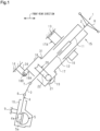
FIG. 1] FIG. 1 is a schematic diagram illustrating the configuration of a steering device according to an embodiment. - [
FIG. 2] FIG. 2 is a perspective view illustrating a state in which a steering column and a housing inFIG. 1 are coupled. - [
FIG. 3] FIG. 3 is a perspective view illustrating a coupling portion between the housing and a lower tube inFIG. 2 . - [
FIG. 4] FIG. 4 is a perspective view of the housing inFIG. 2 . - [
FIG. 5] FIG. 5 is a plan view of the housing inFIG. 2 . - [
FIG. 6] FIG. 6 is a plan view illustrating the profile of the housing inFIG. 2 . - [
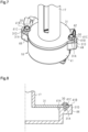
FIG. 7] FIG. 7 is a perspective view illustrating a coupling portion between a steering column and a housing according to a comparative example. - [
FIG. 8] FIG. 8 is a half sectional view of the steering column and the housing according to the comparative example, taken along the axes thereof. - [
FIG. 9] FIG. 9 is a plan view illustrating the profile of a housing according to a different embodiment. - [
FIG. 10] FIG. 10 is a plan view of a housing according to a different embodiment. - [
FIG. 11] FIG. 11 is a perspective view illustrating a coupling portion between a steering column and a housing according to a different embodiment. - A steering device according to an embodiment will be described.
- As illustrated in
FIG. 1 , thesteering device 1 includes asteering shaft 2, anintermediate shaft 3, apinion shaft 4, and arack shaft 5. Asteering wheel 6 is coupled to a first end portion of thesteering shaft 2. A first end portion of theintermediate shaft 3 is coupled to a second end portion of thesteering shaft 2 via a universal joint 7. A first end portion of thepinion shaft 4 is coupled to a second end portion of theintermediate shaft 3 via a universal joint 8. A pinion 4a is provided at a second end portion of thepinion shaft 4. The pinion 4a is meshed with arack 5a provided on arack shaft 5. Therack shaft 5 is supported inside a housing 10 fixed to a frame 9 of a vehicle body. Therack shaft 5 is movable in the right direction or the left direction with respect to the advancing direction of a vehicle. Both end portions of therack shaft 5 are coupled to right and left steered wheels (not illustrated) via tie rods (not illustrated). - The
steering shaft 2 includes anouter shaft 11 and aninner shaft 12. Theouter shaft 11 and theinner shaft 12 are coupled to each other by a spline connection, for example. Theouter shaft 11 and theinner shaft 12 are rotatable together and relatively movable along the axial direction. Thesteering shaft 2 is provided obliquely with respect to the front-rear direction of a vehicle with thesteering wheel 6 facing upward. - The
steering device 1 includes asteering column 15. Thesteering shaft 2 is inserted through thesteering column 15. Thesteering shaft 2 is supported so as to be rotatable with respect to thesteering column 15 via a bearing (not illustrated). Thesteering column 15 is attached to twoframes frame 13 is positioned rearward of theother frame 14 in the front-rear direction of the vehicle. - The
steering column 15 includes anupper tube 16, alower tube 17, and ahousing 18. Theupper tube 16 is in a cylindrical shape. Thelower tube 17 is in a cylindrical shape, and includes aflange 31. Theupper tube 16 and thelower tube 17 are fitted with each other. Theupper tube 16 is inserted into a first end portion of thelower tube 17, by way of example. The first end portion is an end portion on the opposite side of a second end portion at which theflange 31 is provided. Theupper tube 16 and thelower tube 17 are movable relative to each other in the axial direction of thesteering shaft 2. Thelower tube 17 includes acolumn bracket 17A. Thelower tube 17 is attached to theframe 13 of the vehicle body via thecolumn bracket 17A. - The
upper tube 16 and thelower tube 17 constitute a support tube that supports thesteering shaft 2 such that thesteering shaft 2 is rotatable. - The
housing 18 is coupled to the second end portion of thelower tube 17. Thehousing 18 includes twosupport portions 18A (only one is illustrated inFIG. 1 ) and asupport shaft 18B. The twosupport portions 18A are provided on a surface of thehousing 18 on the opposite side of thelower tube 17. The twosupport portions 18A face each other in the width direction of the vehicle body. Thesupport shaft 18B extends between the twosupport portions 18A. Thesupport shaft 18B is rotatably coupled to abracket 24 fixed to theframe 14 of the vehicle body. - A
motor 19 that assists in steering is provided outside thehousing 18. Aspeed reducer 20 is housed inside thehousing 18. Thespeed reducer 20 reduces the speed of rotation of themotor 19, and transfers the rotation at the reduced speed to theinner shaft 12. Thespeed reducer 20 is a worm speed reducer that includes aworm 21 and aworm wheel 22. Theworm 21 is coupled to an output shaft (not illustrated) of themotor 19 so as to be rotatable together. The axis of theworm 21 and the axis of the output shaft of themotor 19 are positioned on the same line. Theworm wheel 22 is meshed with theworm 21. Theworm wheel 22 is provided so as to be rotatable together with theinner shaft 12. The axis of theworm wheel 22 and the axis of theinner shaft 12 are positioned on the same line. - The
steering device 1 includes a lock mechanism (not illustrated). The lock mechanism selectively locks and unlocks swing of thesteering column 15 about thesupport shaft 18B and expansion and contraction of thesteering column 15 through an operation of a lever (not illustrated). An unlocking operation of the lever enables thesteering column 15 to swing with respect to thecolumn bracket 17A about thesupport shaft 18B. The vertical position of thesteering wheel 6 can be adjusted by performing the unlocking operation of the lever and thereafter moving thesteering wheel 6 upward or downward. The unlocking operation of the lever also enables theupper tube 16 to move in the axial direction of thesteering shaft 2 with respect to thelower tube 17. The position of thesteering wheel 6 in the axial direction can be adjusted by performing the unlocking operation of the lever and thereafter moving thesteering wheel 6 in the axial direction of thesteering shaft 2. - Next, the configuration of the
lower tube 17 will be described in detail. - As illustrated in
FIG. 2 , thelower tube 17 includes aflange 31. Theflange 31 is provided at the second end portion of thelower tube 17. The second end portion of thelower tube 17 is an end portion on the opposite side of the first end portion into which theupper tube 16 is inserted. Theflange 31 is a flat plate in a circular ring shape. Theflange 31 includes twoattachment portions 31A. The twoattachment portions 31A are provided on the outer peripheral surface of theflange 31. The twoattachment portions 31A project radially outward from the outer peripheral surface of theflange 31. The twoattachment portions 31A are positioned on the opposite sides of each other in the radial direction of theflange 31. As illustrated inFIG. 3 , the twoattachment portions 31A each have aninsertion hole 31B. Abolt 30 is inserted through the insertion holes 31B. Theflange 31 is fixed to thehousing 18 by tightening thebolts 30 to thehousing 18. Thebolts 30 each include ahead portion 30A and ashaft portion 30B. - Next, the configuration of the
housing 18 will be described in detail. - As illustrated in
FIG. 4 , thehousing 18 includes a wormwheel housing member 41 and aworm housing member 42. The wormwheel housing member 41 is in a cylindrical shape, and has anopening portion 41A. Theopening portion 41A opens toward thelower tube 17 along the axis of the wormwheel housing member 41. The outside diameter of the wormwheel housing member 41 is substantially the same as the outside diameter of theflange 31. Theworm housing member 42 is coupled to the outer peripheral surface of the wormwheel housing member 41. Theworm housing member 42 is in a cylindrical shape, and extends in a direction that is orthogonal to the axis of the wormwheel housing member 41. The inside of the wormwheel housing member 41 and the inside of theworm housing member 42 communicate with each other via acommunication hole 43. The wormwheel housing member 41 constitutes a cylindrical portion of thehousing 18. - The
worm wheel 22 is rotatably housed inside the wormwheel housing member 41. Theworm 21 is supported inside theworm housing member 42 so as to be rotatable via a bearing (not illustrated). Theworm wheel 22 and theworm 21 are meshed with each other via thecommunication hole 43 of thehousing 18. - The worm
wheel housing member 41 includes two tighteningportions 44. The tighteningportions 44 are each a portion to which thebolt 30 is tightened when fixing theflange 31 to thehousing 18. The tighteningportions 44 project radially outward from the outer peripheral surface of the wormwheel housing member 41. The two tighteningportions 44 are positioned on the opposite sides of each other in the radial direction of the wormwheel housing member 41. The tighteningportions 44 each have ascrew hole 44A. End surfaces of the tighteningportions 44 in which the screw holes 44A open are flush with an end surface of the wormwheel housing member 41 in which theopening portion 41A opens. - The worm
wheel housing member 41 includes threeregulation portions 41B. Theregulation portions 41B are provided on the outer peripheral surface of the wormwheel housing member 41. Theregulation portions 41B are in a plate shape, and are curved along the outer peripheral surface of the wormwheel housing member 41. Theregulation portions 41B project in an opposite direction of a mounting direction DW of theflange 31 from an end surface of the wormwheel housing member 41 in which theopening portion 41A opens. The mounting direction DW is a direction along the axis of the wormwheel housing member 41, and a direction of getting closer to the wormwheel housing member 41 from a position facing theopening portion 41A. To attach theflange 31 to the wormwheel housing member 41, theflange 31 is moved in the mounting direction DW with respect to the wormwheel housing member 41 to abut against the wormwheel housing member 41. Theregulation portions 41B are spaced from each other in the circumferential direction of the wormwheel housing member 41. Aregulation surface 41C is provided on the inside surface of each of theregulation portions 41B. Theregulation surface 41C is an arcuate surface curved along the outer peripheral surface of the wormwheel housing member 41, and faces radially inward. - As illustrated in
FIG. 5 , the wormwheel housing member 41 is divided into two regions A1 and A2 by a line L1 serving as the boundary when seen in the axial direction of thesteering column 15. The line L1 passes through the center of the wormwheel housing member 41 in the radial direction and the centers of the twoscrew holes 44A in the radial direction. Theworm housing member 42 is positioned in the region A1. Two of the threeregulation portions 41B are positioned in the region A1, and the remaining one is positioned in the region A2. - When seen in the axial direction of the
steering column 15, in addition, the tworegulation portions 41B in the region A1 are positioned on the opposite sides of each other with respect to a line L2. The line L2 is orthogonal to the line L1, and passes through the center of the wormwheel housing member 41 in the radial direction. Theregulation portion 41B in the region A2 is positioned on the line L2. More specifically, theregulation portions 41B are arranged as follows. That is, when seen in the axial direction of thesteering column 15, the tworegulation portions 41B in the region A1 are positioned in the directions of approximately 10:30 and 1:00 with respect to the center of the wormwheel housing member 41 in the radial direction. Theregulation portion 41B in the region A2 is positioned in the direction of approximately 6:00. - When seen in the axial direction of the
steering column 15, theregulation portions 41B are positioned inward of a virtual circle CB. The virtual circle CB is a circle that circumscribes thehead portions 30A of twobolts 30 positioned in the wormwheel housing member 41 on the opposite sides of each other in the direction along the line L1. As illustrated inFIG. 6 , the tworegulation portions 41B in the region A1 are positioned inward of aprofile 18C of thehousing 18 when seen in the axial direction of thehousing 18. That is, the tworegulation portions 41B in the region A1 do not constitute theprofile 18C of thehousing 18. On the contrary, theregulation portion 41B in the region A2 constitutes a part of theprofile 18C of thehousing 18. - Next, a method of assembling the
steering column 15 will be described. Theupper tube 16 and thelower tube 17 are assembled in advance. - To couple the
lower tube 17 and thehousing 18, theflange 31 of thelower tube 17 and theopening portion 41A of thehousing 18 are caused to face each other in the axial direction. In this state, theflange 31 and thehousing 18 are brought closer to each other along the axial direction. At this time, theflange 31 is disposed in a region surrounded by a plurality of theregulation portions 41B while adjusting the rotational position of theflange 31 such that the insertion holes 31B of theflange 31 and thecorresponding screw holes 44A of thehousing 18 coincide with each other. Then, the peripheral edge of theflange 31 abuts against an end surface of the wormwheel housing member 41 in which theopening portion 41A opens. While maintaining such a state of abutment, thebolts 30 are inserted through the insertion holes 31B of theflange 31 from the opposite side of thehousing 18, and the insertedbolts 30 are tightened to the tighteningportions 44 of thehousing 18. Consequently, theflange 31 is fixed to thehousing 18. That is, thelower tube 17 is coupled to thehousing 18 via theflange 31. In addition, theopening portion 41A of thehousing 18 is maintained in the state of being blocked by theflange 31. Theflange 31 also serves as a cover that blocks theopening portion 41A of thehousing 18. - Next, the function of the present embodiment will be described.
- To assemble the
steering column 15, theflange 31 is disposed in a region surrounded by theregulation portions 41B while a portion of the outer peripheral surface of theflange 31 is slid against the regulation surfaces 41C. Theregulation portions 41B guide movement of theflange 31 in the axial direction. A plurality of locations of the outer peripheral surface of theflange 31 in the circumferential direction abuts against the regulation surfaces 41C in the radial direction of theflange 31. That is, theflange 31 and the wormwheel housing member 41 include engagement portions, at which theflange 31 and the wormwheel housing member 41 are engaged with each other in the radial direction of theflange 31, at different locations from the locations of theattachment portions 31A and the tighteningportions 44 at which thebolts 30 are provided. Consequently, the movement of theflange 31 in the radial direction with respect to the wormwheel housing member 41 is regulated. Therefore, thelower tube 17 and thehousing 18 are maintained in the state of being disposed coaxially. Thus, there is no need for the work of adjusting the relative positional relationship between thelower tube 17 and thehousing 18 such that thelower tube 17 and thehousing 18 are disposed coaxially. Since there is no need to perform so-called centering work, thesteering column 15 can be assembled more easily. -
FIG. 7 illustrates the configuration of a comparative example. - As illustrated in
FIG. 7 ,flat surfaces 31D that are orthogonal to the radial direction of theflange 31 are provided at the distal end of theattachment portions 31A of theflanges 31. Theregulation portions 41B are provided on the tighteningportions 44. Theregulation portions 41B are positioned on the outer side in the radial direction of theflange 31 with respect to thecorresponding attachment portions 31A of theflange 31. The regulation surfaces 41C are flat surfaces that are parallel to theflat surfaces 31D of thecorresponding attachment portions 31A. The regulation surfaces 41C and theflat surfaces 31D are maintained in the state of contacting each other with thelower tube 17 and thehousing 18 assembled. - In assembling the
lower tube 17 and thehousing 18, rotation of theflange 31 about the axis is regulated with theflat surfaces 31D of theflange 31 guided by the correspondingregulation surfaces 41C that are also flat surfaces. Therefore, the attachment posture of theflange 31 in the rotational direction is determined. In addition, the movement of theflange 31 in the radial direction is regulated with theflat surfaces 31D abutting against the corresponding regulation surfaces 41C in the radial direction of theflange 31. Therefore, thelower tube 17 and thehousing 18 are maintained in the state of being disposed coaxially. - This comparative example can also eliminate the need for so-called centering work. However, this comparative example involves the following apprehension.
- As illustrated in
FIG. 8 , theregulation portions 41B are positioned on the outer side in the radial direction of theflange 31 with respect to theattachment portions 31A of theflange 31. Therefore, the size of the wormwheel housing member 41 in the radial direction is increased by an amount corresponding to the thickness of theregulation portions 41B in the radial direction of the wormwheel housing member 41. - In the present embodiment, in this respect, the engagement portions of the
flange 31 and the wormwheel housing member 41, that is, theregulation portions 41B, are positioned away from the locations at which thebolts 30 are provided in the circumferential direction of theflange 31 and the wormwheel housing member 41. Therefore, theregulation portions 41B can be positioned inward of the virtual circle CB that circumscribes thehead portions 30A of the twobolts 30 when seen in the axial direction of the wormwheel housing member 41. Therefore, an increase in the size of the wormwheel housing member 41 in the radial direction can be suppressed compared to the comparative example in which theregulation portions 41B are positioned on the outer side in the radial direction of theflange 31 with respect to theattachment portions 31A of theflange 31. - According to the present embodiment, the following effects can be obtained.
- (1) When assembling the
lower tube 17 and thehousing 18, the movement of theflange 31 along the axial direction is guided by theregulation portions 41B. That is, the movement of theflange 31 in the radial direction is regulated by theregulation portions 41B. Therefore, thelower tube 17 and thehousing 18 are maintained in the state of being disposed coaxially. There is no need to perform so-called centering work, thereby improving the efficiency in the work of assembling thelower tube 17 and thehousing 18. Thus, thesteering column 15 can be assembled more easily. - (2) The worm
wheel housing member 41 includes theregulation portions 41B at different locations from the locations of the tighteningportions 44 through which thebolts 30 are passed. Therefore, theregulation portions 41B can be provided so as to be positioned inward of the virtual circle CB that circumscribes thehead portions 30A of the twobolts 30 when seen in the axial direction of thesteering column 15. Thus, an increase in the size of the wormwheel housing member 41 in the radial direction can be suppressed compared to when theregulation portions 41B are provided to protrude outward of the virtual circle CB as in the comparative example inFIG. 7 . In addition, the installation space for thesteering device 1 in the vehicle can be secured easily. - (3) The two
regulation portions 41B in the region A1 are positioned inward of theprofile 18C of thehousing 18 when seen in the axial direction of thehousing 18. That is, the tworegulation portions 41B in the region A1 do not constitute theprofile 18C of thehousing 18. Therefore, interference between theregulation portions 41B and the other parts can be suppressed during the work of assembling thesteering device 1 or the work of attaching thesteering device 1 to the vehicle. - (4) The three
regulation portions 41B are spaced from each other in the circumferential direction of the wormwheel housing member 41. That is, theflange 31 is supported from three different radial directions. Therefore, the movement of theflange 31 in the radial direction can be regulated appropriately when assembling thelower tube 17 and thehousing 18. - (5) The three
regulation portions 41B are provided in a distributed manner in the two regions A1 and A2 of the wormwheel housing member 41 divided by the line L1 serving as the boundary when seen in the axial direction of the wormwheel housing member 41. Therefore, theflange 31 can be supported from significantly different directions. Thus, the movement of theflange 31 in the radial direction can be regulated more appropriately. - The present embodiment may be modified as follows.
- As illustrated in
FIG. 9 , the wormwheel housing member 41 may include tworegulation portions 41B. In this case, the tworegulation portions 41B are preferably positioned on the opposite sides of each other in the radial direction of the wormwheel housing member 41. For example, when seen in the axial direction of the wormwheel housing member 41, theregulation portion 41B in the region A1 is provided in the direction of approximately 10:30, and theregulation portion 41B in the region A2 is provided in the direction of approximately 4:30, with respect to the center of the wormwheel housing member 41 in the radial direction. This also makes it possible to regulate the movement of theflange 31 in the radial direction when assembling thelower tube 17 and thehousing 18. The wormwheel housing member 41 may include four ormore regulation portions 41B. - As illustrated in
FIG. 10 , theregulation portion 41B in the region A2 may be provided so as not to protrude outward of the outer peripheral surface of the wormwheel housing member 41 when seen in the axial direction of the wormwheel housing member 41. For example, theregulation portion 41B in the region A2 is provided in an end surface of the wormwheel housing member 41 in which theopening portion 41A opens. However, the outside surface of theregulation portion 41B in the region A2 is flush with the outer peripheral surface of the wormwheel housing member 41, or is positioned on the radially inner side with respect to the outer peripheral surface of the wormwheel housing member 41. Anotch 31C corresponding to theregulation portion 41B in the region A2 is provided in the peripheral edge portion of theflange 31. When assembling theflange 31 and thehousing 18, theregulation portion 41B in the region A2 is housed inside thenotch 31C of theflange 31. With this configuration, it is possible to reduce a portion that protrudes outward of the outer peripheral surface of the wormwheel housing member 41. By providing theregulation portion 41B, in addition, theflange 31 cannot be assembled to thehousing 18 because of the absence of thenotch 31C, even if it is attempted to assemble theflange 31 to thehousing 18 as erroneously inverted by 180 degrees. Therefore, erroneous assembly can be suppressed. - As illustrated in
FIG. 11 , theregulation portions 41B may be provided on theflange 31. For example, theregulation portions 41B are omitted from the wormwheel housing member 41, and instead coupled to the outer peripheral surface of theflange 31. Theflange 31 may be provided integrally with theregulation portions 41B by plastically deforming a metal plate material punched into a predetermined shape. The size of theregulation portions 41B is changeable as appropriate. Theregulation portions 41B project in the mounting direction DW of theflange 31 from the back surface of theflange 31 facing the wormwheel housing member 41. This also allows theflange 31 and the wormwheel housing member 41 to include engagement portions, at which theflange 31 and the wormwheel housing member 41 are engaged with each other in the radial direction of theflange 31, at different locations from the locations of theattachment portions 31A and the tighteningportions 44 at which thebolts 30 are provided. That is, theregulation portions 41B of theflange 31 abut, in the radial direction of theflange 31, against the outer peripheral surface of the wormwheel housing member 41 at a plurality of locations in the circumferential direction. Therefore, the movement of theflange 31 in the radial direction is regulated when assembling thelower tube 17 and thehousing 18. Theregulation portions 41B may be provided on both the wormwheel housing member 41 and theflange 31. - The
steering device 1 may not be provided with components for adjusting the vertical position of thesteering wheel 6, or components for adjusting the position of thesteering wheel 6 in the axial direction, depending on the product specifications etc. In this case, a single support tube that is not expandable or contractible is provided in place of theupper tube 16 and thelower tube 17. This single support tube supports thesteering shaft 2 such that thesteering shaft 2 is rotatable. In addition, thehousing 18 is fixed to theframe 14 of the vehicle body. Thesupport portions 18A and thesupport shaft 18B can be omitted from thehousing 18. In addition, there is no need for a lock mechanism that selectively locks and unlocks swing of thesteering column 15 about thesupport shaft 18B and expansion and contraction of thesteering column 15.
Claims (8)
- A steering device comprising:a cylindrical support tube that includes a flange and that supports a steering shaft such that the steering shaft is rotatable;a speed reducer configured to apply torque to the steering shaft;a housing that includes a cylindrical portion that houses the speed reducer, the cylindrical portion being disposed coaxially with the flange; anda bolt that couples the flange and the cylindrical portion to each other, wherein the flange and the cylindrical portion include an engagement portion, at which the flange and the cylindrical portion are engaged with each other in a radial direction of the flange, at a different location from a location at which the bolt is provided.
- The steering device according to claim 1, wherein the engagement portion is positioned at a location away from the location at which the bolt is provided in a circumferential direction of the support tube.
- The steering device according to claim 1 or 2, wherein:the bolt includes a plurality of bolts;the bolts are spaced from each other along a circle centered on an axis of the support tube;the bolts each include a head portion and a shaft portion; andthe engagement portion is positioned inward of a virtual circle that circumscribes head portions of the bolts when seen in an axial direction of the support tube.
- The steering device according to any one of claims 1 to 3, wherein the engagement portion is positioned inward of a profile of the housing when seen in an axial direction of the support tube.
- The steering device according to any one of claims 1 to 4, wherein:the engagement portion includes a plurality of regulation portions provided on an outer peripheral surface of the cylindrical portion;the regulation portions are spaced from each other in a circumferential direction of the cylindrical portion; andthe regulation portions each include an inside surface that faces and is engaged with an outer peripheral surface of the flange in the radial direction of the flange.
- The steering device according to any one of claims 1 to 4, wherein:the engagement portion includes a plurality of regulation portions provided on an outer peripheral surface of the flange;the regulation portions are spaced from each other in a circumferential direction of the flange; andthe regulation portions each include an inside surface that faces and is engaged with an outer peripheral surface of the cylindrical portion in the radial direction of the flange.
- The steering device according to claim 5 or 6, wherein at least a part of the regulation portions is positioned inward of a profile of the housing when seen in an axial direction of the support tube.
- The steering device according to any one of claims 1 to 7, wherein:the speed reducer includes a worm wheel that rotates together with the steering shaft and a worm to be meshed with the worm wheel;the housing includes a worm wheel housing member that houses the worm wheel and a worm housing member that houses the worm; andthe cylindrical portion is the worm wheel housing member.
Applications Claiming Priority (1)
| Application Number | Priority Date | Filing Date | Title |
|---|---|---|---|
| PCT/JP2021/024116 WO2022269900A1 (en) | 2021-06-25 | 2021-06-25 | Steering device |
Publications (3)
| Publication Number | Publication Date |
|---|---|
| EP4360996A1 true EP4360996A1 (en) | 2024-05-01 |
| EP4360996A4 EP4360996A4 (en) | 2024-08-21 |
| EP4360996B1 EP4360996B1 (en) | 2026-04-29 |
Family
ID=84544353
Family Applications (1)
| Application Number | Title | Priority Date | Filing Date |
|---|---|---|---|
| EP21947183.6A Active EP4360996B1 (en) | 2021-06-25 | 2021-06-25 | Steering device |
Country Status (5)
| Country | Link |
|---|---|
| US (1) | US20240286666A1 (en) |
| EP (1) | EP4360996B1 (en) |
| JP (1) | JP7529910B2 (en) |
| CN (1) | CN117500714A (en) |
| WO (1) | WO2022269900A1 (en) |
Family Cites Families (11)
| Publication number | Priority date | Publication date | Assignee | Title |
|---|---|---|---|---|
| JP5129690B2 (en) * | 2008-08-18 | 2013-01-30 | 株式会社ミツバ | Motor with reduction mechanism |
| JP5614391B2 (en) | 2011-09-28 | 2014-10-29 | 日本精工株式会社 | Electric assist device |
| US8584359B1 (en) * | 2012-02-22 | 2013-11-19 | Thomas W. Bowman | Floating ring gear epicyclic gear system |
| EP2913246B1 (en) * | 2012-10-29 | 2019-03-27 | NSK Ltd. | Electric power-steering device |
| JP2014227040A (en) * | 2013-05-22 | 2014-12-08 | 株式会社ジェイテクト | Electric power steering apparatus |
| JP2015160579A (en) * | 2014-02-28 | 2015-09-07 | 日本精工株式会社 | Electric power steering device, control device |
| JP6332469B2 (en) * | 2014-11-25 | 2018-05-30 | 日本精工株式会社 | Housing for electric power steering device |
| JP6401076B2 (en) * | 2015-02-23 | 2018-10-03 | 株式会社ショーワ | Housing structure and steering device |
| JP6658039B2 (en) | 2015-04-16 | 2020-03-04 | 日本精工株式会社 | Reduction gear and electric power steering device |
| JP6876249B2 (en) * | 2017-04-19 | 2021-05-26 | 株式会社ジェイテクト | Warm reducer and electric power steering device |
| CN111247050B (en) * | 2017-10-30 | 2022-05-03 | 日本精工株式会社 | Gear box for electric power steering device, method for manufacturing gear box for electric power steering device, and electric power steering device |
-
2021
- 2021-06-25 WO PCT/JP2021/024116 patent/WO2022269900A1/en not_active Ceased
- 2021-06-25 CN CN202180099534.2A patent/CN117500714A/en active Pending
- 2021-06-25 JP JP2023529404A patent/JP7529910B2/en active Active
- 2021-06-25 EP EP21947183.6A patent/EP4360996B1/en active Active
- 2021-06-25 US US18/572,007 patent/US20240286666A1/en active Pending
Also Published As
| Publication number | Publication date |
|---|---|
| WO2022269900A1 (en) | 2022-12-29 |
| US20240286666A1 (en) | 2024-08-29 |
| EP4360996A4 (en) | 2024-08-21 |
| EP4360996B1 (en) | 2026-04-29 |
| JP7529910B2 (en) | 2024-08-06 |
| JPWO2022269900A1 (en) | 2022-12-29 |
| CN117500714A (en) | 2024-02-02 |
Similar Documents
| Publication | Publication Date | Title |
|---|---|---|
| EP3647157B1 (en) | Vehicle steering apparatus | |
| US10597068B2 (en) | Vehicle steering system with steer-by-wire system and mechanical fallback system | |
| EP3611075B1 (en) | Steering device support bracket and steering device | |
| US8727065B2 (en) | Electric power steering device | |
| US20200070644A1 (en) | Final drive mounted motor for track-type tractor | |
| EP2607202A1 (en) | Steering device | |
| US7930950B2 (en) | Motor-driven steering assist apparatus | |
| EP3705375B1 (en) | Gear housing for electric power steering device, manufacturing method thereof, and electric power steering device | |
| EP1920989A2 (en) | Tilt-type steering apparatus | |
| US20070295552A1 (en) | Electric power steering apparatus | |
| EP2607201A1 (en) | Steering device | |
| CN110733558A (en) | Steering device | |
| US20230331282A1 (en) | Rake actuator assembly for steering column and method of assembly | |
| US6431601B2 (en) | Electric power steering apparatus | |
| JP3698289B2 (en) | Car steering device | |
| EP4360996B1 (en) | Steering device | |
| EP2862782A1 (en) | Steering lock device | |
| EP1813507B1 (en) | Electric power steering apparatus | |
| KR20070091224A (en) | Electric power steering | |
| EP4491491A1 (en) | Steering device | |
| JP3900397B2 (en) | Steering shaft assembly structure | |
| US20230132450A1 (en) | Steering device | |
| US20240286665A1 (en) | Steering device | |
| EP2607184B1 (en) | Steering device | |
| US20070235246A1 (en) | Vehicle Steering System And Assembling Method Thereof |
Legal Events
| Date | Code | Title | Description |
|---|---|---|---|
| STAA | Information on the status of an ep patent application or granted ep patent |
Free format text: STATUS: THE INTERNATIONAL PUBLICATION HAS BEEN MADE |
|
| PUAI | Public reference made under article 153(3) epc to a published international application that has entered the european phase |
Free format text: ORIGINAL CODE: 0009012 |
|
| STAA | Information on the status of an ep patent application or granted ep patent |
Free format text: STATUS: REQUEST FOR EXAMINATION WAS MADE |
|
| 17P | Request for examination filed |
Effective date: 20231221 |
|
| AK | Designated contracting states |
Kind code of ref document: A1 Designated state(s): AL AT BE BG CH CY CZ DE DK EE ES FI FR GB GR HR HU IE IS IT LI LT LU LV MC MK MT NL NO PL PT RO RS SE SI SK SM TR |
|
| A4 | Supplementary search report drawn up and despatched |
Effective date: 20240723 |
|
| RIC1 | Information provided on ipc code assigned before grant |
Ipc: B62D 1/189 20060101ALI20240718BHEP Ipc: B62D 5/04 20060101AFI20240718BHEP |
|
| DAV | Request for validation of the european patent (deleted) | ||
| DAX | Request for extension of the european patent (deleted) | ||
| GRAP | Despatch of communication of intention to grant a patent |
Free format text: ORIGINAL CODE: EPIDOSNIGR1 |
|
| STAA | Information on the status of an ep patent application or granted ep patent |
Free format text: STATUS: GRANT OF PATENT IS INTENDED |
|
| RIC1 | Information provided on ipc code assigned before grant |
Ipc: B62D 5/04 20060101AFI20251113BHEP Ipc: B62D 1/189 20060101ALI20251113BHEP |
|
| INTG | Intention to grant announced |
Effective date: 20251119 |
|
| GRAS | Grant fee paid |
Free format text: ORIGINAL CODE: EPIDOSNIGR3 |
|
| RAP1 | Party data changed (applicant data changed or rights of an application transferred) |
Owner name: JTEKT CORPORATION |
|
| GRAA | (expected) grant |
Free format text: ORIGINAL CODE: 0009210 |
|
| STAA | Information on the status of an ep patent application or granted ep patent |
Free format text: STATUS: THE PATENT HAS BEEN GRANTED |
|
| AK | Designated contracting states |
Kind code of ref document: B1 Designated state(s): AL AT BE BG CH CY CZ DE DK EE ES FI FR GB GR HR HU IE IS IT LI LT LU LV MC MK MT NL NO PL PT RO RS SE SI SK SM TR |
|
| RAP3 | Party data changed (applicant data changed or rights of an application transferred) |
Owner name: JTEKT CORPORATION |
|
| REG | Reference to a national code |
Ref country code: CH Ref legal event code: F10 Free format text: ST27 STATUS EVENT CODE: U-0-0-F10-F00 (AS PROVIDED BY THE NATIONAL OFFICE) Effective date: 20260429 Ref country code: GB Ref legal event code: FG4D |