EP4360922A1 - Integrated channel apparatus for non-heat pump thermal management integrated module, and electric vehicle - Google Patents
Integrated channel apparatus for non-heat pump thermal management integrated module, and electric vehicle Download PDFInfo
- Publication number
- EP4360922A1 EP4360922A1 EP22862677.6A EP22862677A EP4360922A1 EP 4360922 A1 EP4360922 A1 EP 4360922A1 EP 22862677 A EP22862677 A EP 22862677A EP 4360922 A1 EP4360922 A1 EP 4360922A1
- Authority
- EP
- European Patent Office
- Prior art keywords
- channel
- component
- strip groove
- groove
- integrated
- Prior art date
- Legal status (The legal status is an assumption and is not a legal conclusion. Google has not performed a legal analysis and makes no representation as to the accuracy of the status listed.)
- Granted
Links
Images




Classifications
-
- B—PERFORMING OPERATIONS; TRANSPORTING
- B60—VEHICLES IN GENERAL
- B60L—PROPULSION OF ELECTRICALLY-PROPELLED VEHICLES; SUPPLYING ELECTRIC POWER FOR AUXILIARY EQUIPMENT OF ELECTRICALLY-PROPELLED VEHICLES; ELECTRODYNAMIC BRAKE SYSTEMS FOR VEHICLES IN GENERAL; MAGNETIC SUSPENSION OR LEVITATION FOR VEHICLES; MONITORING OPERATING VARIABLES OF ELECTRICALLY-PROPELLED VEHICLES; ELECTRIC SAFETY DEVICES FOR ELECTRICALLY-PROPELLED VEHICLES
- B60L58/00—Methods or circuit arrangements for monitoring or controlling batteries or fuel cells, specially adapted for electric vehicles
- B60L58/10—Methods or circuit arrangements for monitoring or controlling batteries or fuel cells, specially adapted for electric vehicles for monitoring or controlling batteries
- B60L58/24—Methods or circuit arrangements for monitoring or controlling batteries or fuel cells, specially adapted for electric vehicles for monitoring or controlling batteries for controlling the temperature of batteries
- B60L58/26—Methods or circuit arrangements for monitoring or controlling batteries or fuel cells, specially adapted for electric vehicles for monitoring or controlling batteries for controlling the temperature of batteries by cooling
-
- B—PERFORMING OPERATIONS; TRANSPORTING
- B60—VEHICLES IN GENERAL
- B60H—ARRANGEMENTS OF HEATING, COOLING, VENTILATING OR OTHER AIR-TREATING DEVICES SPECIALLY ADAPTED FOR PASSENGER OR GOODS SPACES OF VEHICLES
- B60H1/00—Heating, cooling or ventilating devices
- B60H1/00507—Details, e.g. mounting arrangements, desaeration devices
- B60H1/00557—Details of ducts or cables
- B60H1/00571—Details of ducts or cables of liquid ducts, e.g. for coolant liquids or refrigerants
-
- B—PERFORMING OPERATIONS; TRANSPORTING
- B60—VEHICLES IN GENERAL
- B60H—ARRANGEMENTS OF HEATING, COOLING, VENTILATING OR OTHER AIR-TREATING DEVICES SPECIALLY ADAPTED FOR PASSENGER OR GOODS SPACES OF VEHICLES
- B60H1/00—Heating, cooling or ventilating devices
- B60H1/00271—HVAC devices specially adapted for particular vehicle parts or components and being connected to the vehicle HVAC unit
- B60H1/00278—HVAC devices specially adapted for particular vehicle parts or components and being connected to the vehicle HVAC unit for the battery
-
- B—PERFORMING OPERATIONS; TRANSPORTING
- B60—VEHICLES IN GENERAL
- B60H—ARRANGEMENTS OF HEATING, COOLING, VENTILATING OR OTHER AIR-TREATING DEVICES SPECIALLY ADAPTED FOR PASSENGER OR GOODS SPACES OF VEHICLES
- B60H1/00—Heating, cooling or ventilating devices
- B60H1/00485—Valves for air-conditioning devices, e.g. thermostatic valves
-
- B—PERFORMING OPERATIONS; TRANSPORTING
- B60—VEHICLES IN GENERAL
- B60H—ARRANGEMENTS OF HEATING, COOLING, VENTILATING OR OTHER AIR-TREATING DEVICES SPECIALLY ADAPTED FOR PASSENGER OR GOODS SPACES OF VEHICLES
- B60H1/00—Heating, cooling or ventilating devices
- B60H1/32—Cooling devices
- B60H1/3204—Cooling devices using compression
- B60H1/3229—Cooling devices using compression characterised by constructional features, e.g. housings, mountings, conversion systems
-
- B—PERFORMING OPERATIONS; TRANSPORTING
- B60—VEHICLES IN GENERAL
- B60H—ARRANGEMENTS OF HEATING, COOLING, VENTILATING OR OTHER AIR-TREATING DEVICES SPECIALLY ADAPTED FOR PASSENGER OR GOODS SPACES OF VEHICLES
- B60H1/00—Heating, cooling or ventilating devices
- B60H1/00271—HVAC devices specially adapted for particular vehicle parts or components and being connected to the vehicle HVAC unit
- B60H2001/00307—Component temperature regulation using a liquid flow
-
- B—PERFORMING OPERATIONS; TRANSPORTING
- B60—VEHICLES IN GENERAL
- B60Y—INDEXING SCHEME RELATING TO ASPECTS CROSS-CUTTING VEHICLE TECHNOLOGY
- B60Y2200/00—Type of vehicle
- B60Y2200/90—Vehicles comprising electric prime movers
- B60Y2200/91—Electric vehicles
-
- B—PERFORMING OPERATIONS; TRANSPORTING
- B60—VEHICLES IN GENERAL
- B60Y—INDEXING SCHEME RELATING TO ASPECTS CROSS-CUTTING VEHICLE TECHNOLOGY
- B60Y2304/00—Optimising design; Manufacturing; Testing
- B60Y2304/07—Facilitating assembling or mounting
- B60Y2304/076—Facilitating assembling or mounting by add-on parts, e.g. retrofit
Definitions
- the present invention relates to a technical field of an electric vehicle, in particular to an integrated channel apparatus for a non-heat pump thermal management integrated module and an electric vehicle.
- a pure electric vehicle is a vehicle driven by an electric motor, and the thermal management system of the pure electric vehicle is divided into a heat pump system and a non-heat pump system.
- the vehicle with the heat pump system and the vehicle with the non-heat pump system need to be designed separately due to their different components, this means that the designer and manufacturer of the electric vehicle need to design the electric vehicle with the heat pump platform and the electric vehicle with the non-heat pump platform separately, especially, for the heat pump thermal management module and the non-heat pump thermal management module.
- the vast majority of parts have now been integrated into the thermal management module, for the pipeline interface used to control the refrigerant circulation, a device that can quickly switch between the heat pump system and the non-heat pump system has not yet been designed due to the characteristics of the thermal management in the heat pump system and the non-heat pump system.
- An integrated channel apparatus for a non-heat pump thermal management integrated module includes a first component and a second component, the first component is provided with a channel group and a groove; the channel group includes multiple channels, the channel is used to accommodate a connecting tube, each channel runs through the first component along a thickness direction of the first component, and the groove is provided on one side of the first component for accommodating the connecting tube; the second component is provided with a strip groove group; the strip groove group includes multiple strip grooves, each strip groove is provided corresponding to two channels in the multiple channels and is used to connect the two channels, and the channels corresponding to each strip groove are different; a flank of the first component away from the groove is hermetically connected to a mating surface of the second component.
- the technical effect of the integrated channel apparatus provided by the present invention is that: during use, the integrated channel apparatus is installed in the non-heat pump thermal management integrated module, the connecting tubes that need to be connected are placed in the two channels and the strip groove correspondingly connecting the two channels, the connecting tubes that do not need to be connected are placed in the grooves; when needing to be upgraded and retrofitted to a heat pump management system, the integrated channel apparatus is disassembled, a three-way valve or a four-way valve is adaptively installed on the exposed connecting tubes according to the user's requirement to form a nine-way valve required for the heat pump management system, and then other heat pump components are additionally installed; by adjusting the nine-way valve adaptively, different connection modes between various connecting tubes can be achieved, thereby achieving the corresponding mode requirements of the heat pump management system.
- the integrated channel apparatus provided in the present disclosure can quickly upgrade the electric vehicle from the non-heat pump system to the heat pump system without significantly increasing the cost and weight of the entire vehicle.
- An electric vehicle provided by the present invention includes a vehicle body, a thermal integration management module, and the above integrated channel apparatus for a non-heat pump thermal management integrated module, the thermal integration management module is installed on the vehicle body, and the integrated channel apparatus is installed on the thermal integration management module.
- the technical effect of the electric vehicle provided by the present invention is that: as including the above integrated channel apparatus, the electric vehicle also has the technical effect that quickly upgrading the electric vehicle from the non-heat pump system to the heat pump system without significantly increasing the cost and weight of the entire vehicle.
- the vehicle with the heat pump system and the vehicle with the non-heat pump system need to be designed separately due to their different components, this means that the designer and manufacturer of the electric vehicle need to design the electric vehicle with the heat pump platform and the electric vehicle with the non-heat pump platform separately, especially, for the heat pump thermal management module and the non-heat pump thermal management module.
- the vast majority of parts have now been integrated into the thermal management module, for the pipeline interface used to control the refrigerant circulation, a device that can quickly switch between the heat pump system and the non-heat pump system has not yet been designed due to the characteristics of the thermal management in the heat pump system and the non-heat pump system.
- an integrated channel apparatus for a non-heat pump thermal management integrated module includes a first component and a second component, which form a two-by-two connecting channels for placing connecting tubes, when upgrading and retrofitting to a heat pump management system, the integrated channel apparatus is disassembled, a three-way valve or a four-way valve is adaptively installed on the exposed connecting tubes, and then other heat pump components are additionally installed, the three-way valve or the four-way valve is adaptively adjusted, different connection modes between various connecting tubes can be achieved, thereby achieving the corresponding mode requirements of the heat pump management system.
- an integrated channel apparatus for a non-heat pump thermal management integrated module and an electric vehicle provided by the present invention
- the integrated channel apparatus includes a first component and a second component.
- the first component is provided with a channel group and a groove;
- the channel group includes multiple channels, the channel is used to accommodate a connecting tube, each channel runs through the first component along a thickness direction of the first component, and the groove is provided on one side of the first component for accommodating the connecting tube;
- the second component is provided with a strip groove group;
- the strip groove group includes multiple strip grooves, each strip groove is provided corresponding to two channels in the multiple channels and is used to connect the two channels, and the channels corresponding to each strip groove are different; a flank of the first component away from the groove is hermetically connected to a mating surface of the second component.
- the integrated channel apparatus provided by the present disclosure is installed in the non-heat pump thermal management integrated module, the connecting tubes that need to be connected are placed in the two channels and the strip groove correspondingly connecting the two channels, the connecting tubes that do not need to be connected are placed in the grooves; when needing to be upgraded and retrofitted to a heat pump management system, the integrated channel apparatus is disassembled, a three-way valve or a four-way valve is adaptively installed on the exposed connecting tubes according to the user's requirement to form a nine-way valve required for the heat pump management system, and then other heat pump components are additionally installed; by adjusting the nine-way valve adaptively, different connection modes between various connecting tubes can be achieved, thereby achieving the corresponding mode requirements of the heat pump management system.
- the integrated channel apparatus provided in the present disclosure can quickly upgrade the electric vehicle from the non-heat pump system to the heat pump system without significantly increasing the cost and weight of the entire vehicle.
- an electric vehicle provided by the present disclosure also has the above technical effect.
- the integrated channel apparatus for a non-heat pump thermal management integrated module includes a first component 11 and a second component 12.
- the first component 11 is provided with a channel group and a groove 119;
- the channel group includes multiple channels, the channel is used to accommodate a connecting tube, each channel runs through the first component 11 along a thickness direction of the first component 11, and the groove 119 is provided on one side of the first component 11 for accommodating the connecting tube.
- the second component 12 is provided with a strip groove group;
- the strip groove group include multiple strip grooves, each strip groove is provided corresponding to two channels in the multiple channels and is used to connect the two channels, and the channels corresponding to each strip groove are different; a flank of the first component 11 away from the groove 119 is hermetically connected to a mating surface of the second component 12.
- the first component 11 provided by the present disclosure is provided with a channel group and a groove 119; the channel group includes multiple channels, the channel is used to accommodate a connecting tube, each channel runs through the first component 11 along a thickness direction of the first component 11, and the groove 119 is provided on one side of the first component 11 for accommodating the connecting tube.
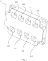
- the channel group includes a first channel 111, a second channel 112, a third channel 113, a fourth channel 114, a fifth channel 115, a sixth channel 116, a seventh channel 117, and an eighth channel 118;
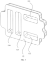
- the strip groove group includes a first strip groove 121, a second strip groove 122, a third strip groove 123, and a fourth strip groove 124;
- the first strip groove 121 connects the first channel 111 and the second channel 112;
- the second strip groove 122 connects the fourth channel 114 and the third channel 113;
- the third strip groove 123 connects the seventh channel 117 and the eighth channel 118;
- the fourth strip groove 124 connects the sixth channel 116 and the fifth channel 115.
- the number of channels included in the channel group is not limited here, in other specific embodiments, the number of channels provided on the first component 11 can be set to other appropriate values according to the specific needs of the user. It should be noted that the number of strip grooves included in the strip groove group is not limited here, in other specific embodiments, the number of strip grooves provided on the second component 12 can be set to other appropriate values according to the specific needs of the user.
- the channel group on the first component 11 is arranged into a rectangular array, a row direction of the rectangular array is a first direction, and a column direction of the rectangular array is a second direction;
- the second channel 112 the first channel 111, the seventh channel 117, and the sixth channel 116 are located in a first row;
- the third channel 113, the fourth channel 114, the eighth channel 118, and the fifth channel 115 are located in a third row;
- the groove 119 is provided in a second row between the first row and the third row, and is placed between the seventh channel 117 and the eighth channel 118;
- the first strip groove 121 and the second strip groove 122 are parallel and spaced, the first strip groove 121 is provided corresponding to the first row, and the second strip groove 122 is provided corresponding to the third row;
- the third strip groove 123 and the fourth strip groove 124 are parallel, the third strip groove 123 spans the first row, the second row, and the third row, and the fourth strip groove 124 spans the first row
- the channel group on the first component 11 is arranged into a rectangular array, the eight channels are set to three rows, and the strip groove is connected with the two corresponding channels, by using this arrangement and combination manner, the channel group and the strip groove group are connected and docked in an effectively and orderly manner, and the structure is simple, the arrangement does not exist in the form of staggering, so that the connecting tubes do not interfere with each other and the setting of the connecting tubes is more neat and orderly, and avoiding to occupy too much space.
- the first component 11 and the second component 12 are both provided as plate like structures. It should be noted that both the first component 11 and the second component 12 are provided as plate like structures, so that there is a connection plane between the first component 11 and the second component 12, and it is also convenient to achieve a sealed connection. It can be understood that the specific structures of 11 and the second component 12 are not limited here, in other specific embodiments, the first component 11 and the second component 12 can also be provided as other structures with connecting planes according to user's requirements.
- the shape and size of the edge of the mating surfaces of the first component 11 and the second component 12 can be exactly the same. As the size and shape of the mating surfaces of the first component 11 and the second component 12 are the same, it is convenient to connect the mating surfaces of the first component 11 and the second component 12.
- the edges of the first component 11 and the second component 12 can be set as small as possible around the channel group, that is, the side walls of the first component 11 and the second component 12 can have a concave and convex structure to reduce space occupation and reduce the weight of the entire vehicle.
- the mating surfaces of the first component 11 and the second component 12 are hot plate welded.
- the hot plate welding adopts a draw-plate structure, and the heat of the heating plate machine is transferred to fusion surfaces of upper and lower plastic heating parts, so as to melt the surfaces, and then the heating plate machine is quickly withdrawn by using the electric heating method. After heating, the two pieces of upper and lower heating parts, the melting surfaces are fused, solidified, and merged into one.
- the hot plate welding is simple to operate and is convenient to use, and after fusion, it can achieve a watertight and airtight fusion effect, and effectively prevent the liquid in the connecting tube from overflowing out of the connection of the first component 11 and the second component 12, which thus ensures the stability of the connection between the first component 11 and the second component 12.
- the integrated channel apparatus provided by the present disclosure further includes a sealing ring 13, the sealing ring 13 is provided in edges of the channel and the groove away from the second component. It should be noted that providing the sealing ring 13 can effectively ensure the sealing of the connection between the external component and the first component 11 when the first component 11 is externally connected with a component, and can effectively prevent the liquid in the connecting tube from overflowing along the connecting surface.
- the channel and the groove 119 are provided with raised edges perpendicular to the first component 11; and the sealing ring 13 is sleeved in the raised edges.
- the edge of the sealing ring 13 is provided as a sleeve structure, and is sleeved in the channel and the groove 119 with the raised edge perpendicular to the first component 11, which ensures that when the first component 11 is not connected to the external component, the sealing ring 13 can be installed on the raised edge first, effectively ensuring the connection stability of the sealing ring 13, at the same time, the raised edge is provided along the edge of the channel and the groove 119, which can make the design of the sealing ring 13 more compact, avoid waste caused by the excessive sealing ring 13, and save costs.
- the sealing ring 13 provided in all the channels and the groove 119 is constructed into an integral structure. It should be noted that the sealing ring 13 provided in all the channels and the groove 119 is constructed into an integral structure, which facilitates the corresponding installation, while avoids the phenomenon of missing or falling off when using a single setting and single installation.
- the integrated channel apparatus further includes multiple connecting tubes, each connecting tube includes two end parts and a connecting part located between the two end parts, the connecting part is accommodated in the strip groove, and the two end parts are respectively inserted in the two channels connected by the strip groove.
- multiple connecting tubes are provided to be placed in the strip grooves and the channels for use in the non-heat pump thermal management integrated module, which facilitates the direct exposure of the connecting tubes after removing the first component 11 and the second component 12 during retrofitting and upgrading, facilitates the installation of appropriate three-way valves or four-way valves on the connections, and facilitates the achievement of quick conversion.
- the connecting tubes includes a first connecting tube 141, a second connecting tube 142, a third connecting tube 143, and a fourth connecting tube 144.
- first connecting tube 141 passes through the first strip groove 121
- second connecting tube 142 passes through the second strip groove 122
- third connecting tube 143 passes through the third strip groove 123
- fourth connecting tube 144 passes through the fourth strip groove 124.
- An electric vehicle provided by the present disclosure includes a vehicle body, a thermal integration management module, and the above integrated channel apparatus for a non-heat pump thermal management integrated module, the thermal integration management module is installed on the vehicle body, and the integrated channel apparatus is installed on the thermal integration management module.
- the electric vehicle provided by the present disclosure also has the above technical effect, which can facilitate the achievement of quick retrofitting and upgrading without increasing self weight and cost.
- the electric vehicle provided by the present disclosure further includes an installation bracket, where the installation bracket is hermetically connected to one side of the first component 11 away from the second component 12, and the installation bracket has multiple installation positions, the multiple installation positions are correspondingly connected with the multiple channels and the groove 119 one by one.
- the installation bracket is provided to be hermetically connected to the first component 11, which facilitates placing the pipeline connected to the connecting tube directly on the installation bracket, and directly achieves that the pipeline inside the installation bracket is connected to the connecting tube inside the channel during installation.
- the pipelines that do not need to be connected to other pipelines can be placed in the groove 119.
- the connection bracket has nine installation positions, the nine installation positions are correspondingly connected with eight channels and one groove one by one.
- the heat pump system of the electric vehicle generally includes the following components: an expansion kettle, a motor water pump assembly, a battery water pump assembly, a heating water pump assembly, a heat exchanger, a water-cooled condenser, a water temperature sensor, a four-way solenoid valve, a three-way solenoid valve, a two-way solenoid valve, a two-way proportional valve, a three-way proportional valve, a cooling connection pipeline, an air conditioning liquid-air separator, an air conditioning EXV valve, an air conditioning SOV valve, an air conditioning connection pipeline, etc.
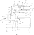
- the principle diagram of the heat pump thermal management integration module includes a thermal engine cooling loop and a battery cooling loop; the flow direction of the thermal engine cooling loop is as follows: radiator outlet connection 151 ⁇ first four-way valve 191 ⁇ motor water pump 153 ⁇ water-cooled condenser 154 ⁇ second four-way valve 192 ⁇ return to radiator water inlet connection port 152.
- a cooling water container 155 is provided between the radiator and the motor water pump 153; a two-way proportional valve 156 is provided between the motor water pump 153 and the water-cooled condenser 154; a first water temperature sensor 161 is provided at the water outlet of the radiator.
- the flow direction of the battery cooling loop is as follows: battery pack water outlet connection port 171 ⁇ second four-way valve 192 ⁇ heating element water inlet connection port 172 ⁇ heating element water outlet connection port 173 ⁇ heat exchanger 174 ⁇ first four-way valve 191 ⁇ motor water pump 153 ⁇ battery pack water inlet connection port 176; where a second water temperature sensor 162 and a third water temperature sensor 163 are respectively provided before and after the heat exchanger 174, and a fourth water temperature sensor 164 is provided before the battery pack water inlet connection port 176.
- a branch is also provided between the drying bottle 179 and the electronic expansion valve 181, the branch is connected with a build-in evaporator inlet connection port 184, an electronic expansion valve 181 is also provided before the build-in evaporator inlet connection port 184.
- a three-way valve 193 is also provided between the second four-way valve 192 and the returning radiator water inlet connection port 152, and another interface of the three-way valve 193 is connected to the first four-way valve 191.
- the principle diagram of the non-heat pump system eliminates the first four-way valve 191, the second four-way valve 192, the three-way valve 193, the build-in evaporator inlet connection port 184, the electronic expansion valve 181 provided before the build-in evaporator inlet connection port 184, and the drying bottle 179 on the basic of the heat pump system.
- the non-heat pump thermal management integrated module includes a thermal engine cooling loop and a battery cooling loop; the flow direction of the thermal engine cooling loop is as follows: radiator water outlet connection port 151 ⁇ second channel 112- first channel 111 ⁇ motor water pump 153 ⁇ water-cooled condenser 154 ⁇ eighth channel 118- seventh channel 117 ⁇ return to radiator water inlet connection port 152.
- a cooling water container 155 is provided between the radiator and the motor water pump 153; a two-way proportional valve 156 is provided between the motor water pump 153 and the water-cooled condenser 154; a first water temperature sensor 161 is provided at the water outlet of the radiator.
- the flow direction of the battery cooling loop is as follows: battery pack water outlet connection port 171 ⁇ sixth channel 116 ⁇ fifth channel 115 ⁇ heating element water inlet connection port 172 ⁇ heating element water outlet connection port 173 ⁇ heat exchanger 174 ⁇ fourth channel 114 ⁇ third channel 113 ⁇ motor water pump 153 ⁇ battery pack water inlet connection port 176; where a second water temperature sensor 162 and a third water temperature sensor 163 are respectively provided before and after the heat exchanger 174, and a fourth water temperature sensor 164 is provided before the battery pack water inlet connection port 176.
- a groove 119 is provided between the seventh channel 117 and the eighth channel 118, and the groove 119 does not affect the connection between the seventh channel 117 and the eighth channel 118.
- the first component 11 and the second component 12 of the present disclosure are directly disassembled, and a corresponding valve is installed on the exposed connecting tubes, such as the first four-way valve 191 is installed at the exposed connecting tube of the first channel 111, the second channel 112, the third channel 113, and the fourth channel 114, and the second four-way valve 192 is installed at the exposed connecting tube of the fifth channel 115, the sixth channel 116 and the eighth channel 118, and the three-way valve 193 is installed at the exposed connecting tube of the seventh channel 117 and the groove 119, which can quickly upgrade the non-heat pump thermal management integrated module to the heat pump thermal management integration module.
- a corresponding valve is installed on the exposed connecting tubes, such as the first four-way valve 191 is installed at the exposed connecting tube of the first channel 111, the second channel 112, the third channel 113, and the fourth channel 114, and the second four-way valve 192 is installed at the exposed connecting tube of the fifth channel 115, the sixth channel 116 and the eighth channel 118, and the
Landscapes
- Engineering & Computer Science (AREA)
- Mechanical Engineering (AREA)
- Physics & Mathematics (AREA)
- Thermal Sciences (AREA)
- Sustainable Energy (AREA)
- Sustainable Development (AREA)
- Life Sciences & Earth Sciences (AREA)
- Power Engineering (AREA)
- Transportation (AREA)
- Air-Conditioning For Vehicles (AREA)
- Secondary Cells (AREA)
- Electric Propulsion And Braking For Vehicles (AREA)
- Cooling, Air Intake And Gas Exhaust, And Fuel Tank Arrangements In Propulsion Units (AREA)
Abstract
Description
- The present invention relates to a technical field of an electric vehicle, in particular to an integrated channel apparatus for a non-heat pump thermal management integrated module and an electric vehicle.
- A pure electric vehicle is a vehicle driven by an electric motor, and the thermal management system of the pure electric vehicle is divided into a heat pump system and a non-heat pump system.
- In a prior art, the vehicle with the heat pump system and the vehicle with the non-heat pump system need to be designed separately due to their different components, this means that the designer and manufacturer of the electric vehicle need to design the electric vehicle with the heat pump platform and the electric vehicle with the non-heat pump platform separately, especially, for the heat pump thermal management module and the non-heat pump thermal management module. Although the vast majority of parts have now been integrated into the thermal management module, for the pipeline interface used to control the refrigerant circulation, a device that can quickly switch between the heat pump system and the non-heat pump system has not yet been designed due to the characteristics of the thermal management in the heat pump system and the non-heat pump system. For example, when it is needed to upgrade the electric vehicle with the non-heat pump system to the electric vehicle with the heat pump system, existing electric vehicle manufacturers and designers do not have mature solutions. In order to achieve platform universality, some manufacturers can only use the same pipeline interface as the heat pump system, which not only increases the cost of the entire vehicle, but also increases its weight, resulting in a decrease in the cruising ability of the entire vehicle.
- Therefore, it is necessary to design a device to quickly upgrade the electric vehicle from the non-heat pump system to the heat pump system without significantly increasing the cost and weight of the entire vehicle.
- An integrated channel apparatus for a non-heat pump thermal management integrated module provided by the present invention includes a first component and a second component, the first component is provided with a channel group and a groove; the channel group includes multiple channels, the channel is used to accommodate a connecting tube, each channel runs through the first component along a thickness direction of the first component, and the groove is provided on one side of the first component for accommodating the connecting tube; the second component is provided with a strip groove group; the strip groove group includes multiple strip grooves, each strip groove is provided corresponding to two channels in the multiple channels and is used to connect the two channels, and the channels corresponding to each strip groove are different; a flank of the first component away from the groove is hermetically connected to a mating surface of the second component.
- The technical effect of the integrated channel apparatus provided by the present invention is that: during use, the integrated channel apparatus is installed in the non-heat pump thermal management integrated module, the connecting tubes that need to be connected are placed in the two channels and the strip groove correspondingly connecting the two channels, the connecting tubes that do not need to be connected are placed in the grooves; when needing to be upgraded and retrofitted to a heat pump management system, the integrated channel apparatus is disassembled, a three-way valve or a four-way valve is adaptively installed on the exposed connecting tubes according to the user's requirement to form a nine-way valve required for the heat pump management system, and then other heat pump components are additionally installed; by adjusting the nine-way valve adaptively, different connection modes between various connecting tubes can be achieved, thereby achieving the corresponding mode requirements of the heat pump management system. The integrated channel apparatus provided in the present disclosure can quickly upgrade the electric vehicle from the non-heat pump system to the heat pump system without significantly increasing the cost and weight of the entire vehicle.
- An electric vehicle provided by the present invention includes a vehicle body, a thermal integration management module, and the above integrated channel apparatus for a non-heat pump thermal management integrated module, the thermal integration management module is installed on the vehicle body, and the integrated channel apparatus is installed on the thermal integration management module.
- The technical effect of the electric vehicle provided by the present invention is that: as including the above integrated channel apparatus, the electric vehicle also has the technical effect that quickly upgrading the electric vehicle from the non-heat pump system to the heat pump system without significantly increasing the cost and weight of the entire vehicle.
- By referring to the following detailed description of the accompanying drawings, the above and other purposes, features, and advantages of the embodiments of the present invention will become easier to understand. In the accompanying drawings, multiple embodiments of the present invention will be explained in an exemplary and non-limiting manner, where:
-
FIG. 1 is an overall structural schematic diagram of an integrated channel apparatus provided by an embodiment of the present disclosure; -
FIG. 2 is an overall structural schematic diagram of a second component and connecting tubes of an integrated channel apparatus provided by an embodiment of the present disclosure; -
FIG. 3 is a structural schematic diagram of a first component of an integrated channel apparatus under a first perspective provided by an embodiment of the present disclosure; -
FIG. 4 is a structural schematic diagram of a first component of an integrated channel apparatus under a second perspective provided by an embodiment of the present disclosure; -
FIG. 5 is a structural schematic diagram of a second component of an integrated channel apparatus provided by an embodiment of the present disclosure; -
FIG. 6 is a structural schematic diagram of a sealing ring of an integrated channel apparatus provided by an embodiment of the present disclosure; -
FIG. 7 is a principle diagram of retrofitting as a heat pump management integration module provided by an embodiment of the present disclosure; -
FIG. 8 is a principle diagram of a non-heat pump management integration module installed with an integration apparatus provided by an embodiment of the present disclosure. -
- 11-first component; 111- first channel;
- 112-second channel; 113-third channel;
- 114-fourth channel; 115-fifth channel;
- 116-sixth channel; 117-seventh channel;
- 118-eighth channel; 119-groove;
- 12-second component; 121 first strip groove;
- 122-second strip groove; 123-third strip groove;
- 124-fourth strip groove;
- 13-sealing ring;
- 141-first connecting tube; 142-second connecting tube;
- 143-third connecting tube; 144-fourth connecting tube;
- 151-radiator water outlet connection port; 152-radiator water inlet connection port;
- 153-motor water pump; 154-water-cooled condenser;
- 155-cooling water container; 156-two-way proportional valve;
- 161-first water temperature sensor; 162-second water temperature sensor;
- 163-third water temperature sensor; 164-fourth water temperature sensor;
- 171-battery pack water outlet connection port; 172-heating element water inlet connection port;
- 173-heating element water outlet connection port; 174-heat exchanger;
- 175-motor water pump; 176-battery pack water inlet connection port;
- 177-built-in cooling condenser inlet connection port;
- 178-built-in cooling condenser outlet connection port; 179-drying bottle;
- 181-electronic expansion valve;
- 182-compressor inlet connection port; 183-compressor outlet connection port;
- 184-build-in evaporator inlet connection port;
- 191-first four-way valve; 192-second four-way valve;
- 193-three-way valve.
- In a prior art, the vehicle with the heat pump system and the vehicle with the non-heat pump system need to be designed separately due to their different components, this means that the designer and manufacturer of the electric vehicle need to design the electric vehicle with the heat pump platform and the electric vehicle with the non-heat pump platform separately, especially, for the heat pump thermal management module and the non-heat pump thermal management module. Although the vast majority of parts have now been integrated into the thermal management module, for the pipeline interface used to control the refrigerant circulation, a device that can quickly switch between the heat pump system and the non-heat pump system has not yet been designed due to the characteristics of the thermal management in the heat pump system and the non-heat pump system. For example, when it is needed to upgrade the electric vehicle with the non-heat pump system to the electric vehicle with the heat pump system, existing electric vehicle manufacturers and designers do not have mature solutions. In order to achieve platform universality, some manufacturers can only use the same pipeline interface as the heat pump system, which not only increases the cost of the entire vehicle, but also increases its weight, resulting in a decrease in the cruising ability of the entire vehicle.
- Therefore, it is necessary to design a device to quickly upgrade the electric vehicle from the non-heat pump system to the heat pump system without significantly increasing the cost and weight of the entire vehicle.
- In view of this, an integrated channel apparatus for a non-heat pump thermal management integrated module provided by an embodiment of the present application includes a first component and a second component, which form a two-by-two connecting channels for placing connecting tubes, when upgrading and retrofitting to a heat pump management system, the integrated channel apparatus is disassembled, a three-way valve or a four-way valve is adaptively installed on the exposed connecting tubes, and then other heat pump components are additionally installed, the three-way valve or the four-way valve is adaptively adjusted, different connection modes between various connecting tubes can be achieved, thereby achieving the corresponding mode requirements of the heat pump management system.
- In particular, an integrated channel apparatus for a non-heat pump thermal management integrated module and an electric vehicle provided by the present invention, the integrated channel apparatus includes a first component and a second component. The first component is provided with a channel group and a groove; the channel group includes multiple channels, the channel is used to accommodate a connecting tube, each channel runs through the first component along a thickness direction of the first component, and the groove is provided on one side of the first component for accommodating the connecting tube; the second component is provided with a strip groove group; the strip groove group includes multiple strip grooves, each strip groove is provided corresponding to two channels in the multiple channels and is used to connect the two channels, and the channels corresponding to each strip groove are different; a flank of the first component away from the groove is hermetically connected to a mating surface of the second component. During use, the integrated channel apparatus provided by the present disclosure is installed in the non-heat pump thermal management integrated module, the connecting tubes that need to be connected are placed in the two channels and the strip groove correspondingly connecting the two channels, the connecting tubes that do not need to be connected are placed in the grooves; when needing to be upgraded and retrofitted to a heat pump management system, the integrated channel apparatus is disassembled, a three-way valve or a four-way valve is adaptively installed on the exposed connecting tubes according to the user's requirement to form a nine-way valve required for the heat pump management system, and then other heat pump components are additionally installed; by adjusting the nine-way valve adaptively, different connection modes between various connecting tubes can be achieved, thereby achieving the corresponding mode requirements of the heat pump management system. The integrated channel apparatus provided in the present disclosure can quickly upgrade the electric vehicle from the non-heat pump system to the heat pump system without significantly increasing the cost and weight of the entire vehicle. As including the above integrated channel device mentioned, an electric vehicle provided by the present disclosure also has the above technical effect.
- Referring to
FIGs. 1 to 6 , the integrated channel apparatus for a non-heat pump thermal management integrated module provided by an embodiment of the present application includes afirst component 11 and asecond component 12. thefirst component 11 is provided with a channel group and agroove 119; the channel group includes multiple channels, the channel is used to accommodate a connecting tube, each channel runs through thefirst component 11 along a thickness direction of thefirst component 11, and thegroove 119 is provided on one side of thefirst component 11 for accommodating the connecting tube. thesecond component 12 is provided with a strip groove group; the strip groove group include multiple strip grooves, each strip groove is provided corresponding to two channels in the multiple channels and is used to connect the two channels, and the channels corresponding to each strip groove are different; a flank of thefirst component 11 away from thegroove 119 is hermetically connected to a mating surface of thesecond component 12. - The
first component 11 provided by the present disclosure is provided with a channel group and agroove 119; the channel group includes multiple channels, the channel is used to accommodate a connecting tube, each channel runs through thefirst component 11 along a thickness direction of thefirst component 11, and thegroove 119 is provided on one side of thefirst component 11 for accommodating the connecting tube. Exemplarily, the channel group includes afirst channel 111, asecond channel 112, athird channel 113, afourth channel 114, afifth channel 115, asixth channel 116, aseventh channel 117, and aneighth channel 118; the strip groove group includes afirst strip groove 121, asecond strip groove 122, athird strip groove 123, and afourth strip groove 124; thefirst strip groove 121 connects thefirst channel 111 and thesecond channel 112; thesecond strip groove 122 connects thefourth channel 114 and thethird channel 113;thethird strip groove 123 connects theseventh channel 117 and theeighth channel 118; thefourth strip groove 124 connects thesixth channel 116 and thefifth channel 115. It should be noted that the number of channels included in the channel group is not limited here, in other specific embodiments, the number of channels provided on thefirst component 11 can be set to other appropriate values according to the specific needs of the user. It should be noted that the number of strip grooves included in the strip groove group is not limited here, in other specific embodiments, the number of strip grooves provided on thesecond component 12 can be set to other appropriate values according to the specific needs of the user. - Exemplarily, the channel group on the
first component 11 is arranged into a rectangular array, a row direction of the rectangular array is a first direction, and a column direction of the rectangular array is a second direction; thesecond channel 112, thefirst channel 111, theseventh channel 117, and thesixth channel 116 are located in a first row; thethird channel 113, thefourth channel 114, theeighth channel 118, and thefifth channel 115 are located in a third row; thegroove 119 is provided in a second row between the first row and the third row, and is placed between theseventh channel 117 and theeighth channel 118; thefirst strip groove 121 and thesecond strip groove 122 are parallel and spaced, thefirst strip groove 121 is provided corresponding to the first row, and thesecond strip groove 122 is provided corresponding to the third row; thethird strip groove 123 and thefourth strip groove 124 are parallel, thethird strip groove 123 spans the first row, the second row, and the third row, and thefourth strip groove 124 spans the first row, the second row, and the third row; thefirst strip groove 121 is vertically provided with the three strip grooves. It should be noted that the channel group on thefirst component 11 is arranged into a rectangular array, the eight channels are set to three rows, and the strip groove is connected with the two corresponding channels, by using this arrangement and combination manner, the channel group and the strip groove group are connected and docked in an effectively and orderly manner, and the structure is simple, the arrangement does not exist in the form of staggering, so that the connecting tubes do not interfere with each other and the setting of the connecting tubes is more neat and orderly, and avoiding to occupy too much space. - Exemplarily, the
first component 11 and thesecond component 12 are both provided as plate like structures. It should be noted that both thefirst component 11 and thesecond component 12 are provided as plate like structures, so that there is a connection plane between thefirst component 11 and thesecond component 12, and it is also convenient to achieve a sealed connection. It can be understood that the specific structures of 11 and thesecond component 12 are not limited here, in other specific embodiments, thefirst component 11 and thesecond component 12 can also be provided as other structures with connecting planes according to user's requirements. - Exemplarily, the shape and size of the edge of the mating surfaces of the
first component 11 and thesecond component 12 can be exactly the same. As the size and shape of the mating surfaces of thefirst component 11 and thesecond component 12 are the same, it is convenient to connect the mating surfaces of thefirst component 11 and thesecond component 12. The edges of thefirst component 11 and thesecond component 12 can be set as small as possible around the channel group, that is, the side walls of thefirst component 11 and thesecond component 12 can have a concave and convex structure to reduce space occupation and reduce the weight of the entire vehicle. - In an optional exemplary embodiment, the mating surfaces of the
first component 11 and thesecond component 12 are hot plate welded. It should be noted that the hot plate welding adopts a draw-plate structure, and the heat of the heating plate machine is transferred to fusion surfaces of upper and lower plastic heating parts, so as to melt the surfaces, and then the heating plate machine is quickly withdrawn by using the electric heating method. After heating, the two pieces of upper and lower heating parts, the melting surfaces are fused, solidified, and merged into one. The hot plate welding is simple to operate and is convenient to use, and after fusion, it can achieve a watertight and airtight fusion effect, and effectively prevent the liquid in the connecting tube from overflowing out of the connection of thefirst component 11 and thesecond component 12, which thus ensures the stability of the connection between thefirst component 11 and thesecond component 12. - In an optional exemplary embodiment, the integrated channel apparatus provided by the present disclosure further includes a sealing
ring 13, the sealingring 13 is provided in edges of the channel and the groove away from the second component. It should be noted that providing the sealingring 13 can effectively ensure the sealing of the connection between the external component and thefirst component 11 when thefirst component 11 is externally connected with a component, and can effectively prevent the liquid in the connecting tube from overflowing along the connecting surface. Exemplarily, the channel and thegroove 119 are provided with raised edges perpendicular to thefirst component 11; and the sealingring 13 is sleeved in the raised edges. It should be noted that the edge of the sealingring 13 is provided as a sleeve structure, and is sleeved in the channel and thegroove 119 with the raised edge perpendicular to thefirst component 11, which ensures that when thefirst component 11 is not connected to the external component, the sealingring 13 can be installed on the raised edge first, effectively ensuring the connection stability of the sealingring 13, at the same time, the raised edge is provided along the edge of the channel and thegroove 119, which can make the design of the sealingring 13 more compact, avoid waste caused by theexcessive sealing ring 13, and save costs. Exemplarily, the sealingring 13 provided in all the channels and thegroove 119 is constructed into an integral structure. It should be noted that the sealingring 13 provided in all the channels and thegroove 119 is constructed into an integral structure, which facilitates the corresponding installation, while avoids the phenomenon of missing or falling off when using a single setting and single installation. - In an optional exemplary embodiment, the integrated channel apparatus provided by the present disclosure further includes multiple connecting tubes, each connecting tube includes two end parts and a connecting part located between the two end parts, the connecting part is accommodated in the strip groove, and the two end parts are respectively inserted in the two channels connected by the strip groove. It should be noted that multiple connecting tubes are provided to be placed in the strip grooves and the channels for use in the non-heat pump thermal management integrated module, which facilitates the direct exposure of the connecting tubes after removing the
first component 11 and thesecond component 12 during retrofitting and upgrading, facilitates the installation of appropriate three-way valves or four-way valves on the connections, and facilitates the achievement of quick conversion. Exemplarily, the connecting tubes includes a first connecting tube 141, a second connecting tube 142, a third connecting tube 143, and a fourth connecting tube 144. Where the first connecting tube 141 passes through thefirst strip groove 121, the second connecting tube 142 passes through thesecond strip groove 122, the third connecting tube 143 passes through thethird strip groove 123, and the fourth connecting tube 144 passes through thefourth strip groove 124. - An electric vehicle provided by the present disclosure includes a vehicle body, a thermal integration management module, and the above integrated channel apparatus for a non-heat pump thermal management integrated module, the thermal integration management module is installed on the vehicle body, and the integrated channel apparatus is installed on the thermal integration management module. As including the above integrated channel device mentioned, the electric vehicle provided by the present disclosure also has the above technical effect, which can facilitate the achievement of quick retrofitting and upgrading without increasing self weight and cost.
- The electric vehicle provided by the present disclosure further includes an installation bracket, where the installation bracket is hermetically connected to one side of the
first component 11 away from thesecond component 12, and the installation bracket has multiple installation positions, the multiple installation positions are correspondingly connected with the multiple channels and thegroove 119 one by one. It should be noted that in the embodiment, the installation bracket is provided to be hermetically connected to thefirst component 11, which facilitates placing the pipeline connected to the connecting tube directly on the installation bracket, and directly achieves that the pipeline inside the installation bracket is connected to the connecting tube inside the channel during installation. At the same time, the pipelines that do not need to be connected to other pipelines can be placed in thegroove 119. Exemplarily, the connection bracket has nine installation positions, the nine installation positions are correspondingly connected with eight channels and one groove one by one. - In order to further illustrate the conversion of the integrated channel apparatus provided by the present disclosure between the non-heat pump management integration module and the heat pump management integration module, the principle of the non-heat pump management system and the heat pump management system are explained as follows:
- Specifically, as shown in
FIG. 7 , the heat pump system of the electric vehicle generally includes the following components: an expansion kettle, a motor water pump assembly, a battery water pump assembly, a heating water pump assembly, a heat exchanger, a water-cooled condenser, a water temperature sensor, a four-way solenoid valve, a three-way solenoid valve, a two-way solenoid valve, a two-way proportional valve, a three-way proportional valve, a cooling connection pipeline, an air conditioning liquid-air separator, an air conditioning EXV valve, an air conditioning SOV valve, an air conditioning connection pipeline, etc. - The principle diagram of the heat pump thermal management integration module includes a thermal engine cooling loop and a battery cooling loop; the flow direction of the thermal engine cooling loop is as follows:
radiator outlet connection 151 → first four-way valve 191 →motor water pump 153 → water-cooledcondenser 154 → second four-way valve 192 → return to radiator waterinlet connection port 152. - It should be noted that a cooling
water container 155 is provided between the radiator and themotor water pump 153; a two-wayproportional valve 156 is provided between themotor water pump 153 and the water-cooledcondenser 154; a firstwater temperature sensor 161 is provided at the water outlet of the radiator. - The flow direction of the battery cooling loop is as follows: battery pack water
outlet connection port 171 → second four-way valve 192 → heating element waterinlet connection port 172 → heating element wateroutlet connection port 173 →heat exchanger 174 → first four-way valve 191 →motor water pump 153 → battery pack waterinlet connection port 176; where a secondwater temperature sensor 162 and a thirdwater temperature sensor 163 are respectively provided before and after theheat exchanger 174, and a fourthwater temperature sensor 164 is provided before the battery pack waterinlet connection port 176. - In the above thermal engine cooling loop and battery cooling loop, there is also a flow cycle between the water-cooled
condenser 154 and theheat exchanger 174, which is as follows: water-cooledcondenser 154 → built-in cooling condenserinlet connection port 177 → built-in cooling condenseroutlet connection port 178 → dryingbottle 179 →electronic expansion valve 181 →heat exchanger 174 → compressorinlet connection port 182 → compressoroutlet connection port 183 → water-cooledcondenser 154. - It should also be noted that a branch is also provided between the drying
bottle 179 and theelectronic expansion valve 181, the branch is connected with a build-in evaporatorinlet connection port 184, anelectronic expansion valve 181 is also provided before the build-in evaporatorinlet connection port 184. - It should also be noted that a three-
way valve 193 is also provided between the second four-way valve 192 and the returning radiator waterinlet connection port 152, and another interface of the three-way valve 193 is connected to the first four-way valve 191. - As shown in
FIG. 8 , the principle diagram of the non-heat pump system eliminates the first four-way valve 191, the second four-way valve 192, the three-way valve 193, the build-in evaporatorinlet connection port 184, theelectronic expansion valve 181 provided before the build-in evaporatorinlet connection port 184, and the dryingbottle 179 on the basic of the heat pump system. - The non-heat pump thermal management integrated module includes a thermal engine cooling loop and a battery cooling loop; the flow direction of the thermal engine cooling loop is as follows: radiator water
outlet connection port 151 → second channel 112-first channel 111 →motor water pump 153 → water-cooledcondenser 154 → eighth channel 118-seventh channel 117 → return to radiator waterinlet connection port 152. - It should be noted that a cooling
water container 155 is provided between the radiator and themotor water pump 153; a two-wayproportional valve 156 is provided between themotor water pump 153 and the water-cooledcondenser 154; a firstwater temperature sensor 161 is provided at the water outlet of the radiator. - The flow direction of the battery cooling loop is as follows: battery pack water
outlet connection port 171 →sixth channel 116 →fifth channel 115 → heating element waterinlet connection port 172 → heating element wateroutlet connection port 173 →heat exchanger 174 →fourth channel 114 →third channel 113 →motor water pump 153 → battery pack waterinlet connection port 176; where a secondwater temperature sensor 162 and a thirdwater temperature sensor 163 are respectively provided before and after theheat exchanger 174, and a fourthwater temperature sensor 164 is provided before the battery pack waterinlet connection port 176. - In the above thermal engine cooling loop and battery cooling loop, there is also a flow cycle between the water-cooled
condenser 154 and theheat exchanger 174, which is as follows: water-cooledcondenser 154 → built-in cooling condenserinlet connection port 177 → built-in cooling condenseroutlet connection port 178 →electronic expansion valve 181 →heat exchanger 174 → compressorinlet connection port 182 → compressoroutlet connection port 183 → water-cooledcondenser 154. - It should also be noted that a
groove 119 is provided between theseventh channel 117 and theeighth channel 118, and thegroove 119 does not affect the connection between theseventh channel 117 and theeighth channel 118. - When it is needed to upgrade and retrofit the non-heat pump thermal management integrated module to the heat pump thermal management integration module, the
first component 11 and thesecond component 12 of the present disclosure are directly disassembled, and a corresponding valve is installed on the exposed connecting tubes, such as the first four-way valve 191 is installed at the exposed connecting tube of thefirst channel 111, thesecond channel 112, thethird channel 113, and thefourth channel 114, and the second four-way valve 192 is installed at the exposed connecting tube of thefifth channel 115, thesixth channel 116 and theeighth channel 118, and the three-way valve 193 is installed at the exposed connecting tube of theseventh channel 117 and thegroove 119, which can quickly upgrade the non-heat pump thermal management integrated module to the heat pump thermal management integration module. - Finally, it should be noted that the above embodiments are only used to illustrate the technical solutions of the present invention, but not to limit them; although the present invention has been described in detail with reference to the foregoing embodiments, person with ordinary skill in the art should understand that: it is still possible to make modifications to the technical solutions described in the foregoing embodiments or to make equivalent replacements for some or all of the technical features therein; and these modifications or replacements do not take the essence of the corresponding technical solutions out of the scope of the technical solutions of the embodiments of the present invention.
- Furthermore, it should be noted that the various specific technical features described in the above specific embodiments can be combined in any suitable manner without contradiction. In order to avoid unnecessary repetition, the present invention does not separately explain various possible combinations.
Claims (10)
- An integrated channel apparatus for a non-heat pump thermal management integrated module, comprising a first component and a second component;the first component is provided with a channel group and a groove;the channel group comprises multiple channels, the channel is used to accommodate a connecting tube, each channel runs through the first component along a thickness direction of the first component, and the groove is provided on one side of the first component for accommodating the connecting tube;the second component is provided with a strip groove group; the strip groove group comprises multiple strip grooves, each strip groove is provided corresponding to two channels in the multiple channels and is used to connect the two channels, and the channels corresponding to each strip groove are different;a flank of the first component away from the groove is hermetically connected to a mating surface of the second component.
- The integrated channel apparatus according to claim 1, wherein the channel group comprises a first channel, a second channel, a third channel, a fourth channel, a fifth channel, a sixth channel, a seventh channel, and an eighth channel;the strip groove group comprises a first strip groove, a second strip groove, a third strip groove, and a fourth strip groove;the first strip groove connects the first channel and the second channel;the second strip groove connects the fourth channel and the third channel;the third strip groove connects the seventh channel and the eighth channel;the fourth strip groove connects the sixth channel and the fifth channel.
- The integrated channel apparatus according to claim 2, wherein the channel group on the first component is arranged into a rectangular array, a row direction of the rectangular array is a first direction, and a column direction of the rectangular array is a second direction;the second channel, the first channel, the seventh channel, and the sixth channel are located in a first row; the third channel, the fourth channel, the eighth channel, and the fifth channel are located in a third row;the groove is provided in a second row between the first row and the third row, and is placed between the seventh channel and the eighth channel;the first strip groove and the second strip groove are parallel and spaced, the first strip groove is provided corresponding to the first row, and the second strip groove is provided corresponding to the third row;the third strip groove and the fourth strip groove are parallel, the third strip groove spans the first row, the second row, and the third row, and the fourth strip groove spans the first row, the second row, and the third row; the first strip groove is vertically provided with the three strip grooves.
- The integrated channel apparatus according to claim 1, wherein mating surfaces of the first component and the second component are hot plate welded.
- The integrated channel apparatus according to any one of claims 1 to 4, further comprising a sealing ring, the sealing ring is provided in edges of the channel and the groove away from the second component.
- The integrated channel apparatus according to claim 5, wherein the channel and the groove are provided with raised edges perpendicular to the first component; and the sealing ring is sleeved in the raised edges.
- The integrated channel apparatus according to claim 5, wherein the sealing ring provided in all the channels and the groove is constructed into an integral structure.
- The integrated channel apparatus according to any one of claims 1 to 4, further comprising multiple connecting tubes, each connecting tube comprises two end parts and a connecting part located between the two end parts, the connecting part is accommodated in the strip groove, and the two end parts are respectively inserted in the two channels connected by the strip groove.
- An electric vehicle, comprising a vehicle body, a thermal integration management module, and the integrated channel apparatus for a non-heat pump thermal management integrated module according to any one of claims 1 to 8, the thermal integration management module is installed on the vehicle body, and the integrated channel apparatus is installed on the thermal integration management module.
- The electric vehicle according to claim 9, further comprising an installation bracket, wherein the installation bracket is hermetically connected to one side of the first component away from the second component, and the installation bracket has multiple installation positions, the multiple installation positions are correspondingly connected with the multiple channels and the groove one by one.
Applications Claiming Priority (2)
| Application Number | Priority Date | Filing Date | Title |
|---|---|---|---|
| CN202111037448.7A CN113715577B (en) | 2021-09-06 | 2021-09-06 | Integrated channel device for non-heat pump thermal management integrated module and electric vehicle |
| PCT/CN2022/089657 WO2023029533A1 (en) | 2021-09-06 | 2022-04-27 | Integrated channel apparatus for non-heat pump thermal management integrated module, and electric vehicle |
Publications (4)
| Publication Number | Publication Date |
|---|---|
| EP4360922A1 true EP4360922A1 (en) | 2024-05-01 |
| EP4360922A4 EP4360922A4 (en) | 2024-12-04 |
| EP4360922B1 EP4360922B1 (en) | 2025-05-21 |
| EP4360922C0 EP4360922C0 (en) | 2025-05-21 |
Family
ID=78681850
Family Applications (1)
| Application Number | Title | Priority Date | Filing Date |
|---|---|---|---|
| EP22862677.6A Active EP4360922B1 (en) | 2021-09-06 | 2022-04-27 | Integrated channel apparatus for non-heat pump thermal management integrated module, and electric vehicle |
Country Status (6)
| Country | Link |
|---|---|
| US (1) | US20240166088A1 (en) |
| EP (1) | EP4360922B1 (en) |
| JP (1) | JP7627810B2 (en) |
| KR (1) | KR20240024229A (en) |
| CN (1) | CN113715577B (en) |
| WO (1) | WO2023029533A1 (en) |
Families Citing this family (2)
| Publication number | Priority date | Publication date | Assignee | Title |
|---|---|---|---|---|
| CN113715577B (en) * | 2021-09-06 | 2023-06-13 | 浙江吉利控股集团有限公司 | Integrated channel device for non-heat pump thermal management integrated module and electric vehicle |
| CN114161904B (en) * | 2021-12-03 | 2025-01-14 | 浙江吉利控股集团有限公司 | Heat pump integrated module and automobile air conditioning system |
Family Cites Families (38)
| Publication number | Priority date | Publication date | Assignee | Title |
|---|---|---|---|---|
| JPS58178194A (en) * | 1982-04-12 | 1983-10-19 | Hitachi Ltd | Heat exchanger |
| EP0328414A3 (en) * | 1988-02-12 | 1989-09-27 | Acr Heat Transfer Manufacturing Limited | Heat exchanger |
| US5214564A (en) * | 1992-04-23 | 1993-05-25 | Sunstrand Corporation | Capacitor assembly with integral cooling apparatus |
| JP3341481B2 (en) * | 1994-08-05 | 2002-11-05 | 株式会社日立製作所 | Fluid branch block and method of manufacturing the same |
| JPH0979616A (en) * | 1995-09-19 | 1997-03-28 | Hitachi Ltd | Air conditioner |
| JPH09196515A (en) * | 1996-01-22 | 1997-07-31 | Izumi Giken:Kk | Piping unit of heat pump type air conditioner |
| JPH1123071A (en) * | 1997-07-08 | 1999-01-26 | Sharp Corp | Air conditioner |
| JP3764703B2 (en) | 2002-06-21 | 2006-04-12 | 三菱重工業株式会社 | Heat exchanger |
| DE102004043773A1 (en) * | 2004-09-10 | 2006-04-13 | Saurer Gmbh & Co. Kg | Ceramic nozzle and crimping device of a synthetic multifilament yarn |
| US8544454B2 (en) * | 2006-03-16 | 2013-10-01 | Behr Gmbh & Co. Kg | Heat exchanger for a motor vehicle |
| US7649731B2 (en) * | 2007-01-31 | 2010-01-19 | Tyco Electronics Corporation | Power distribution module using buss bar |
| JP2009138909A (en) * | 2007-12-10 | 2009-06-25 | Denso Corp | Piping joint device |
| DE102009056043A1 (en) * | 2009-11-27 | 2011-06-01 | GM Global Technology Operations LLC, ( n. d. Ges. d. Staates Delaware ), Detroit | Sealing arrangement for the motor vehicle front wall |
| FR2953917B1 (en) * | 2009-12-10 | 2012-01-20 | Hutchinson | INTERNAL THERMAL EXCHANGER FOR AIR CONDITIONING CIRCUIT OF MOTOR VEHICLE AND SUCH CIRCUIT |
| CN202390428U (en) * | 2011-01-10 | 2012-08-22 | 伊鲁米那股份有限公司 | Fluidic device support |
| JP5887484B2 (en) * | 2011-10-06 | 2016-03-16 | パナソニックIpマネジメント株式会社 | Heat pump water heater |
| JP5997433B2 (en) | 2011-11-28 | 2016-09-28 | マルヤス工業株式会社 | U-turn heat exchanger |
| JP5904108B2 (en) * | 2011-12-19 | 2016-04-13 | 株式会社デンソー | Exhaust heat exchanger |
| FR2995671B1 (en) * | 2012-09-19 | 2014-10-03 | Air Liquide | HEAT EXCHANGER ASSEMBLY AND SEPARATION UNIT COMPRISING SUCH A HEAT EXCHANGER ASSEMBLY |
| US10066878B2 (en) * | 2012-09-29 | 2018-09-04 | Zhejiang Sanhua Automotive Components Co., Ltd. | Heat exchanger integrated assembly and manufacturing method thereof |
| CN104344050A (en) * | 2013-07-25 | 2015-02-11 | 浙江三花汽车零部件有限公司 | Electronic expansion valve |
| US10408511B2 (en) * | 2015-02-25 | 2019-09-10 | Zhejiang Sanhua Automotive Components Co., Ltd. | Heat exchange device |
| KR102371560B1 (en) * | 2015-09-18 | 2022-03-11 | 주식회사 두원공조 | Plate type heat exchanger |
| CN107351624B (en) * | 2016-05-10 | 2020-08-25 | 比亚迪股份有限公司 | Heat pump air conditioning system and electric automobile |
| CN107839496B (en) * | 2016-09-21 | 2019-11-22 | 比亚迪股份有限公司 | Thermal management system of power battery pack and electric vehicle with the same |
| CN106369708B (en) * | 2016-12-01 | 2022-02-18 | 内蒙古创达热管节能设备有限公司 | U-shaped microchannel dehumidification heat pipe and use method thereof |
| JP6925158B2 (en) | 2017-04-26 | 2021-08-25 | 株式会社イズミ技研 | Piping unit for automobile air conditioning and its manufacturing method |
| CN109424806A (en) * | 2017-08-31 | 2019-03-05 | 杭州三花研究院有限公司 | A kind of pipeline switching device |
| CN111098654B (en) * | 2018-10-25 | 2023-10-27 | 株式会社泉技研 | Piping unit for automobile air conditioner and method for manufacturing piping unit for automobile air conditioner |
| CN109774409B (en) * | 2018-12-26 | 2021-01-19 | 爱驰汽车有限公司 | Automobile heat management system |
| CN210197607U (en) * | 2019-07-08 | 2020-03-27 | 广东美的制冷设备有限公司 | Electric control box assembly and air conditioner indoor unit having the same |
| US11453267B2 (en) * | 2019-09-20 | 2022-09-27 | Ford Global Technologies, Llc | Integrated heat pump bundled module mounting manifold |
| CN113229613A (en) * | 2020-01-22 | 2021-08-10 | 黄远华 | Multifunctional air conditioner for dining table |
| CN112432522B (en) * | 2020-03-31 | 2022-09-06 | 杭州三花研究院有限公司 | Heat exchanger |
| CN216033602U (en) | 2021-05-31 | 2022-03-15 | 比亚迪股份有限公司 | Valve bank integrated module |
| CN113237249B (en) * | 2021-06-02 | 2022-11-15 | 浙江吉利控股集团有限公司 | Heat pump system, energy-saving control method of heat pump system and vehicle |
| CN113276630B (en) * | 2021-06-24 | 2022-09-02 | 浙江吉利控股集团有限公司 | Thermal management integrated module and electric vehicle |
| CN113715577B (en) * | 2021-09-06 | 2023-06-13 | 浙江吉利控股集团有限公司 | Integrated channel device for non-heat pump thermal management integrated module and electric vehicle |
-
2021
- 2021-09-06 CN CN202111037448.7A patent/CN113715577B/en active Active
-
2022
- 2022-04-27 KR KR1020247002336A patent/KR20240024229A/en active Pending
- 2022-04-27 WO PCT/CN2022/089657 patent/WO2023029533A1/en not_active Ceased
- 2022-04-27 JP JP2024504586A patent/JP7627810B2/en active Active
- 2022-04-27 EP EP22862677.6A patent/EP4360922B1/en active Active
-
2024
- 2024-01-26 US US18/423,312 patent/US20240166088A1/en active Pending
Also Published As
| Publication number | Publication date |
|---|---|
| US20240166088A1 (en) | 2024-05-23 |
| CN113715577A (en) | 2021-11-30 |
| KR20240024229A (en) | 2024-02-23 |
| JP2024535177A (en) | 2024-09-30 |
| CN113715577B (en) | 2023-06-13 |
| EP4360922A4 (en) | 2024-12-04 |
| JP7627810B2 (en) | 2025-02-06 |
| EP4360922B1 (en) | 2025-05-21 |
| WO2023029533A1 (en) | 2023-03-09 |
| EP4360922C0 (en) | 2025-05-21 |
Similar Documents
| Publication | Publication Date | Title |
|---|---|---|
| JP7808623B2 (en) | Thermal management integrated module and electric vehicle | |
| US20240166088A1 (en) | Integrated channel apparatus for non-heat pump thermal management integrated module, and electric vehicle | |
| WO2022266945A1 (en) | Multi-channel cooling line integration apparatus, thermal management integration module and electric vehicle | |
| CN206148573U (en) | A battery pack thermal management system | |
| CN113829832B (en) | Thermal management system and vehicle | |
| EP4613514A1 (en) | Vehicle thermal management system and vehicle | |
| WO2022253097A1 (en) | Valve group integration module and vehicle having same | |
| EP4541614A1 (en) | Whole vehicle thermal management system and vehicle | |
| EP2629040B1 (en) | A unitary heat pump air conditioner having a heat exchanger with an integral receiver and sub-cooler. | |
| CN102055043B (en) | Battery and battery module | |
| JP6816160B2 (en) | A tank of phase change material with a filling tube for filling the tank for the heat exchanger of an automatic vehicle air conditioner | |
| CN210744096U (en) | Integrated battery heat exchange device and electric automobile | |
| CN113650528A (en) | Thermal Management Modules, Thermal Management Systems and Automotive | |
| EP2413061B1 (en) | Water heater | |
| CN103765130B (en) | Evaporator heat exchanger unit | |
| US20250115099A1 (en) | Thermal management device | |
| CN222875704U (en) | Automobile thermal management integrated module, vehicle thermal management system and vehicle | |
| CN109210811A (en) | Two kinds of temperature two media liquid cooling apparatus | |
| CN207146705U (en) | Radiator and air-conditioner outdoor unit | |
| CN120863332A (en) | Thermal management integrated device and vehicle | |
| CN116742185A (en) | Energy storage device and thermal management device thereof | |
| CN223864658U (en) | Integrated air conditioning system and new energy automobile | |
| CN224094653U (en) | Integrated compressor and new energy automobile | |
| WO2023159629A1 (en) | Water dispenser device | |
| CN224094652U (en) | Integrated compressor and new energy automobile |
Legal Events
| Date | Code | Title | Description |
|---|---|---|---|
| STAA | Information on the status of an ep patent application or granted ep patent |
Free format text: STATUS: THE INTERNATIONAL PUBLICATION HAS BEEN MADE |
|
| PUAI | Public reference made under article 153(3) epc to a published international application that has entered the european phase |
Free format text: ORIGINAL CODE: 0009012 |
|
| STAA | Information on the status of an ep patent application or granted ep patent |
Free format text: STATUS: REQUEST FOR EXAMINATION WAS MADE |
|
| 17P | Request for examination filed |
Effective date: 20240126 |
|
| AK | Designated contracting states |
Kind code of ref document: A1 Designated state(s): AL AT BE BG CH CY CZ DE DK EE ES FI FR GB GR HR HU IE IS IT LI LT LU LV MC MK MT NL NO PL PT RO RS SE SI SK SM TR |
|
| A4 | Supplementary search report drawn up and despatched |
Effective date: 20241031 |
|
| RIC1 | Information provided on ipc code assigned before grant |
Ipc: F28D 7/16 20060101ALI20241025BHEP Ipc: B60H 1/00 20060101AFI20241025BHEP |
|
| DAV | Request for validation of the european patent (deleted) | ||
| DAX | Request for extension of the european patent (deleted) | ||
| GRAP | Despatch of communication of intention to grant a patent |
Free format text: ORIGINAL CODE: EPIDOSNIGR1 |
|
| STAA | Information on the status of an ep patent application or granted ep patent |
Free format text: STATUS: GRANT OF PATENT IS INTENDED |
|
| INTG | Intention to grant announced |
Effective date: 20250227 |
|
| GRAS | Grant fee paid |
Free format text: ORIGINAL CODE: EPIDOSNIGR3 |
|
| GRAA | (expected) grant |
Free format text: ORIGINAL CODE: 0009210 |
|
| STAA | Information on the status of an ep patent application or granted ep patent |
Free format text: STATUS: THE PATENT HAS BEEN GRANTED |
|
| AK | Designated contracting states |
Kind code of ref document: B1 Designated state(s): AL AT BE BG CH CY CZ DE DK EE ES FI FR GB GR HR HU IE IS IT LI LT LU LV MC MK MT NL NO PL PT RO RS SE SI SK SM TR |
|
| REG | Reference to a national code |
Ref country code: GB Ref legal event code: FG4D |
|
| REG | Reference to a national code |
Ref country code: CH Ref legal event code: EP |
|
| REG | Reference to a national code |
Ref country code: DE Ref legal event code: R096 Ref document number: 602022015070 Country of ref document: DE |
|
| REG | Reference to a national code |
Ref country code: IE Ref legal event code: FG4D |
|
| U01 | Request for unitary effect filed |
Effective date: 20250612 |
|
| U07 | Unitary effect registered |
Designated state(s): AT BE BG DE DK EE FI FR IT LT LU LV MT NL PT RO SE SI Effective date: 20250625 |
|
| PG25 | Lapsed in a contracting state [announced via postgrant information from national office to epo] |
Ref country code: ES Free format text: LAPSE BECAUSE OF FAILURE TO SUBMIT A TRANSLATION OF THE DESCRIPTION OR TO PAY THE FEE WITHIN THE PRESCRIBED TIME-LIMIT Effective date: 20250521 |
|
| PG25 | Lapsed in a contracting state [announced via postgrant information from national office to epo] |
Ref country code: NO Free format text: LAPSE BECAUSE OF FAILURE TO SUBMIT A TRANSLATION OF THE DESCRIPTION OR TO PAY THE FEE WITHIN THE PRESCRIBED TIME-LIMIT Effective date: 20250821 |
|
| PG25 | Lapsed in a contracting state [announced via postgrant information from national office to epo] |
Ref country code: PL Free format text: LAPSE BECAUSE OF FAILURE TO SUBMIT A TRANSLATION OF THE DESCRIPTION OR TO PAY THE FEE WITHIN THE PRESCRIBED TIME-LIMIT Effective date: 20250521 |
|
| PG25 | Lapsed in a contracting state [announced via postgrant information from national office to epo] |
Ref country code: HR Free format text: LAPSE BECAUSE OF FAILURE TO SUBMIT A TRANSLATION OF THE DESCRIPTION OR TO PAY THE FEE WITHIN THE PRESCRIBED TIME-LIMIT Effective date: 20250521 |
|
| PG25 | Lapsed in a contracting state [announced via postgrant information from national office to epo] |
Ref country code: RS Free format text: LAPSE BECAUSE OF FAILURE TO SUBMIT A TRANSLATION OF THE DESCRIPTION OR TO PAY THE FEE WITHIN THE PRESCRIBED TIME-LIMIT Effective date: 20250821 |
|
| PG25 | Lapsed in a contracting state [announced via postgrant information from national office to epo] |
Ref country code: IS Free format text: LAPSE BECAUSE OF FAILURE TO SUBMIT A TRANSLATION OF THE DESCRIPTION OR TO PAY THE FEE WITHIN THE PRESCRIBED TIME-LIMIT Effective date: 20250921 |
|
| PG25 | Lapsed in a contracting state [announced via postgrant information from national office to epo] |
Ref country code: SM Free format text: LAPSE BECAUSE OF FAILURE TO SUBMIT A TRANSLATION OF THE DESCRIPTION OR TO PAY THE FEE WITHIN THE PRESCRIBED TIME-LIMIT Effective date: 20250521 |
|
| PG25 | Lapsed in a contracting state [announced via postgrant information from national office to epo] |
Ref country code: CZ Free format text: LAPSE BECAUSE OF FAILURE TO SUBMIT A TRANSLATION OF THE DESCRIPTION OR TO PAY THE FEE WITHIN THE PRESCRIBED TIME-LIMIT Effective date: 20250521 |
|
| PG25 | Lapsed in a contracting state [announced via postgrant information from national office to epo] |
Ref country code: SK Free format text: LAPSE BECAUSE OF FAILURE TO SUBMIT A TRANSLATION OF THE DESCRIPTION OR TO PAY THE FEE WITHIN THE PRESCRIBED TIME-LIMIT Effective date: 20250521 |
|
| PLBE | No opposition filed within time limit |
Free format text: ORIGINAL CODE: 0009261 |
|
| STAA | Information on the status of an ep patent application or granted ep patent |
Free format text: STATUS: NO OPPOSITION FILED WITHIN TIME LIMIT |
|
| REG | Reference to a national code |
Ref country code: CH Ref legal event code: L10 Free format text: ST27 STATUS EVENT CODE: U-0-0-L10-L00 (AS PROVIDED BY THE NATIONAL OFFICE) Effective date: 20260402 |
|
| U20 | Renewal fee for the european patent with unitary effect paid |
Year of fee payment: 5 Effective date: 20260303 |
|
| PGFP | Annual fee paid to national office [announced via postgrant information from national office to epo] |
Ref country code: GB Payment date: 20260203 Year of fee payment: 5 |
|
| 26N | No opposition filed |
Effective date: 20260224 |