EP4360914A1 - Fahrzeugluftreifen - Google Patents
Fahrzeugluftreifen Download PDFInfo
- Publication number
- EP4360914A1 EP4360914A1 EP23198970.8A EP23198970A EP4360914A1 EP 4360914 A1 EP4360914 A1 EP 4360914A1 EP 23198970 A EP23198970 A EP 23198970A EP 4360914 A1 EP4360914 A1 EP 4360914A1
- Authority
- EP
- European Patent Office
- Prior art keywords
- groove
- tread
- grooves
- depth
- pneumatic vehicle
- Prior art date
- Legal status (The legal status is an assumption and is not a legal conclusion. Google has not performed a legal analysis and makes no representation as to the accuracy of the status listed.)
- Granted
Links
Images


Classifications
-
- B—PERFORMING OPERATIONS; TRANSPORTING
- B60—VEHICLES IN GENERAL
- B60C—VEHICLE TYRES; TYRE INFLATION; TYRE CHANGING; CONNECTING VALVES TO INFLATABLE ELASTIC BODIES IN GENERAL; DEVICES OR ARRANGEMENTS RELATED TO TYRES
- B60C11/00—Tyre tread bands; Tread patterns; Anti-skid inserts
- B60C11/03—Tread patterns
- B60C11/13—Tread patterns characterised by the groove cross-section, e.g. for buttressing or preventing stone-trapping
-
- B—PERFORMING OPERATIONS; TRANSPORTING
- B60—VEHICLES IN GENERAL
- B60C—VEHICLE TYRES; TYRE INFLATION; TYRE CHANGING; CONNECTING VALVES TO INFLATABLE ELASTIC BODIES IN GENERAL; DEVICES OR ARRANGEMENTS RELATED TO TYRES
- B60C11/00—Tyre tread bands; Tread patterns; Anti-skid inserts
- B60C11/03—Tread patterns
- B60C11/0306—Patterns comprising block rows or discontinuous ribs
- B60C11/0309—Patterns comprising block rows or discontinuous ribs further characterised by the groove cross-section
-
- B—PERFORMING OPERATIONS; TRANSPORTING
- B60—VEHICLES IN GENERAL
- B60C—VEHICLE TYRES; TYRE INFLATION; TYRE CHANGING; CONNECTING VALVES TO INFLATABLE ELASTIC BODIES IN GENERAL; DEVICES OR ARRANGEMENTS RELATED TO TYRES
- B60C11/00—Tyre tread bands; Tread patterns; Anti-skid inserts
- B60C11/03—Tread patterns
- B60C11/12—Tread patterns characterised by the use of narrow slits or incisions, e.g. sipes
- B60C11/1236—Tread patterns characterised by the use of narrow slits or incisions, e.g. sipes with special arrangements in the tread pattern
- B60C11/125—Tread patterns characterised by the use of narrow slits or incisions, e.g. sipes with special arrangements in the tread pattern arranged at the groove bottom
-
- B—PERFORMING OPERATIONS; TRANSPORTING
- B60—VEHICLES IN GENERAL
- B60C—VEHICLE TYRES; TYRE INFLATION; TYRE CHANGING; CONNECTING VALVES TO INFLATABLE ELASTIC BODIES IN GENERAL; DEVICES OR ARRANGEMENTS RELATED TO TYRES
- B60C11/00—Tyre tread bands; Tread patterns; Anti-skid inserts
- B60C11/03—Tread patterns
- B60C11/13—Tread patterns characterised by the groove cross-section, e.g. for buttressing or preventing stone-trapping
- B60C11/1307—Tread patterns characterised by the groove cross-section, e.g. for buttressing or preventing stone-trapping with special features of the groove walls
- B60C11/1323—Tread patterns characterised by the groove cross-section, e.g. for buttressing or preventing stone-trapping with special features of the groove walls asymmetric
-
- B—PERFORMING OPERATIONS; TRANSPORTING
- B60—VEHICLES IN GENERAL
- B60C—VEHICLE TYRES; TYRE INFLATION; TYRE CHANGING; CONNECTING VALVES TO INFLATABLE ELASTIC BODIES IN GENERAL; DEVICES OR ARRANGEMENTS RELATED TO TYRES
- B60C11/00—Tyre tread bands; Tread patterns; Anti-skid inserts
- B60C11/03—Tread patterns
- B60C11/13—Tread patterns characterised by the groove cross-section, e.g. for buttressing or preventing stone-trapping
- B60C11/1353—Tread patterns characterised by the groove cross-section, e.g. for buttressing or preventing stone-trapping with special features of the groove bottom
-
- B—PERFORMING OPERATIONS; TRANSPORTING
- B60—VEHICLES IN GENERAL
- B60C—VEHICLE TYRES; TYRE INFLATION; TYRE CHANGING; CONNECTING VALVES TO INFLATABLE ELASTIC BODIES IN GENERAL; DEVICES OR ARRANGEMENTS RELATED TO TYRES
- B60C11/00—Tyre tread bands; Tread patterns; Anti-skid inserts
- B60C11/03—Tread patterns
- B60C11/13—Tread patterns characterised by the groove cross-section, e.g. for buttressing or preventing stone-trapping
- B60C11/1369—Tie bars for linking block elements and bridging the groove
-
- B—PERFORMING OPERATIONS; TRANSPORTING
- B60—VEHICLES IN GENERAL
- B60C—VEHICLE TYRES; TYRE INFLATION; TYRE CHANGING; CONNECTING VALVES TO INFLATABLE ELASTIC BODIES IN GENERAL; DEVICES OR ARRANGEMENTS RELATED TO TYRES
- B60C11/00—Tyre tread bands; Tread patterns; Anti-skid inserts
- B60C11/03—Tread patterns
- B60C11/0302—Tread patterns directional pattern, i.e. with main rolling direction
-
- B—PERFORMING OPERATIONS; TRANSPORTING
- B60—VEHICLES IN GENERAL
- B60C—VEHICLE TYRES; TYRE INFLATION; TYRE CHANGING; CONNECTING VALVES TO INFLATABLE ELASTIC BODIES IN GENERAL; DEVICES OR ARRANGEMENTS RELATED TO TYRES
- B60C11/00—Tyre tread bands; Tread patterns; Anti-skid inserts
- B60C11/03—Tread patterns
- B60C11/13—Tread patterns characterised by the groove cross-section, e.g. for buttressing or preventing stone-trapping
- B60C11/1353—Tread patterns characterised by the groove cross-section, e.g. for buttressing or preventing stone-trapping with special features of the groove bottom
- B60C2011/1361—Tread patterns characterised by the groove cross-section, e.g. for buttressing or preventing stone-trapping with special features of the groove bottom with protrusions extending from the groove bottom
Definitions
- the invention relates to pneumatic vehicle tires with a tread with tread blocks which are delimited by oblique grooves reaching the tread depth and by grooves, which grooves are formed between oblique grooves which follow one another in the circumferential direction, in particular with respect to the circumferential direction they run in the opposite direction to the oblique grooves and have groove ends at the oblique grooves and which include grooves which each have a width of 3.0 mm to 10.0 mm, a maximum depth of 65% to 100% of the tread depth, groove flanks extending from the tread periphery and a groove path which runs at its maximum depth and opens into the oblique grooves, which extends obliquely through the respective groove in plan view and runs between a base elevation formed along one groove flank and a base elevation formed along the other groove flank, each base elevation being delimited in the radial direction by an outer surface which, viewed in the cross section running perpendicular to the center line of the groove in plan view, runs parallel to the tread periphery and
- the pneumatic vehicle tire has a tread with shoulder-side profile blocks, half-center profile blocks and center profile blocks, the profile blocks being delimited by oblique grooves extending to the profile depth and grooves running between the oblique grooves.
- the grooves have a width of, for example, 3.0 mm and a maximum depth ("groove depth T N "), which is preferably 3.5 mm less than the profile depth, the profile depth being 8.0 mm to 10.0 mm.
- the maximum depth of the grooves is thus approximately 56% of the profile depth for a profile depth of 8.0 mm and 65% of the profile depth for a profile depth of 10.0 mm.
- the grooves are, viewed in cross section, defined by a running groove base and two groove walls running in the radial direction. At the groove base of each groove there is a notch-like groove path with a width of 0.4 mm to 1.5 mm (“groove”), which extends diagonally through the groove between two base elevations in plan view and crosses the groove over its entire width. Each base elevation is limited in the radial direction by a triangular outer surface running parallel to the tread periphery.
- the tire should have low rolling resistance and uniform wear behavior.
- the base elevations mentioned increase the rigidity of the tread blocks.
- the formation of a groove path running between the base elevations, which is also referred to as a "divider groove”, is advantageous when the tire rolls on the ground, as the tread blocks remain limited in their mobility when they flatten, which helps to maintain low rolling resistance, for example.
- divider groove a groove path running between the base elevations
- the invention is therefore based on the object of increasing the water drainage capacity in the area of the grooves in a pneumatic vehicle tire of the type mentioned at the beginning and noticeably reducing the risk of "stone trapping".
- each base elevation viewed in longitudinal sections of the groove, is inclined at an angle relative to the tread periphery in such a way that the groove in the region of the outer surface has a depth determined in the radial direction, which increases continuously with decreasing width of the outer surface.
- the outer surfaces of the base elevations, which also form the groove base, thus slope in opposite directions to the groove's extension. This design noticeably reduces the likelihood of stones getting caught in the grooves. At the same time, water absorbed by the grooves is drained particularly quickly into the inclined grooves, so that the water drainage capacity in the grooves is increased.
- the outer surface of each base elevation at that groove end at which the depth of the groove is smallest has a greatest distance, determined in the radial direction, of 10% to 90%, in particular 15% to 70%, preferably 20% to 50% of the profile depth from the level of the profile depth.
- a distance ensures that the probability of stones getting caught in the groove is further reduced.
- the specified upper limits of the greatest distance are advantageous for the water drainage capacity of the groove.
- An advantageous embodiment of the first preferred embodiment is that the outer surface of each base elevation at the groove end at which the depth of the groove is greatest has a smallest distance of up to 60%, preferably up to 50%, of the largest distance, determined in the radial direction, from the level of the tread depth.
- the ratio of the smallest distance to the largest distance specifies the angle mentioned in the solution of the problem at which the outer surface is inclined relative to the tread periphery, the specified distances contributing to an improvement in the water drainage behavior in the groove.
- the groove path viewed in plan view, is straight.
- the groove path extends obliquely through the groove such that the outer surface of each Base elevation, viewed from above, has the shape of a right-angled triangle.
- the tread is designed to be directional, with the groove end on the outside of the tread being an incoming groove end that first enters the ground when the tire rolls when driving forward, and the groove end on the inside of the tread being an outgoing groove end.
- the groove and the groove path viewed in plan view, run straight with respect to their center lines and are inclined in the same direction to one another with respect to the circumferential direction, whereby the water drainage in the groove is further improved.
- an advantageous further development consists in that the groove and the groove path, viewed in plan view, in relation to their center lines, each run at an angle to the circumferential direction, wherein the angle at which the groove path runs to the circumferential direction is smaller than the angle at which the groove runs to the circumferential direction.
- the groove path is therefore less inclined to the circumferential direction than the groove, which further improves the water drainage behavior in the area of the groove path.
- the angle at which the groove runs to the circumferential direction is 15° to 40°, in particular from 18° to 35°.
- a further preferred embodiment provides that the outer surface of each base elevation extends to the groove path and has a boundary edge thereon, along which the width of the outer surface continuously decreases.
- the sharp boundary edges help to further reduce the probability of stones becoming jammed in the groove path.
- the groove path has a constant width of 0.5 mm to 1.5 mm, in particular 0.8 mm to 1.2 mm, determined in plan view perpendicular to its center line and related to the boundary edges.
- a groove path designed in this way is advantageous for water drainage, with the corresponding tread blocks supporting each other particularly well via the base elevations adjacent to the groove path when the tire rolls on the ground.
- the base elevations are point-symmetrical with respect to the center of the center line of the groove path.
- the profile blocks delimited by the grooves include shoulder-side profile blocks, wherein the shoulder-side profile blocks are preferably provided with incisions that run in the same direction as the oblique grooves in plan view with respect to the circumferential direction and open into the grooves, with a width of 0.4 mm to 1.6 mm, in particular of up to 1.2 mm, and a maximum depth of 70% to 100% of the profile depth.
- shoulder-side profile blocks are known This is beneficial for the grip properties on wet roads and on roads covered with snow and/or ice.
- the block segments of the shoulder-side tread blocks, which are separated from one another by the cuts, are particularly well supported and stiffened by the base elevations formed in the grooves.
- a further preferred embodiment is characterized in that the profile blocks delimited by the grooves include profile blocks which are jointly delimited by one of the oblique grooves in each circumferential direction, with one of the grooves running between the oblique grooves, with the profile blocks preferably being provided with incisions which, in plan view with respect to the circumferential direction, run in the same direction as the oblique grooves and open into the grooves, with a width of 0.4 mm to 1.6 mm, in particular of up to 1.2 mm, and a maximum depth of 70% to 100% of the profile depth.
- Such profile blocks are advantageous for the grip properties on wet roads and on roads covered with snow and/or ice.
- Pneumatic vehicle tires designed according to the invention are tires for motor vehicles, in particular for multi-track motor vehicles, preferably for Passenger cars, vans or SUVs, and preferably radial tires for rims with an integer rim diameter of 13 to 24 inches.
- Fig.1 shows a plan view of a section of a tread of a pneumatic vehicle tire.
- the tire equatorial plane is marked by a line AA and one side edge of the ground contact area of the tread is marked by a line L.
- the ground contact area corresponds to the statically determined footprint (determined with a tire mounted on a standard rim, load at 70% of the maximum load capacity, internal pressure 85% of the standard pressure, according to ETRTO standards) and has a width B in the axial direction (in Fig.1 B/2 is shown).
- the tread has a directional profile, whereby the pneumatic vehicle tyre must be mounted on the vehicle in such a way that it has the rolling direction indicated by the arrow R when driving forward.
- the tread has a shoulder-side profile block 1, a semi-central profile block 2 spaced from the tire equatorial plane (line AA), which is associated with the shoulder-side profile block 1 and is adjacent to it, and a central profile block 3, which is particularly cut from the tire equatorial plane (line AA).
- a plurality of profile blocks 1, 2, 3 are provided over the circumference of the tread, with the shoulder-side profile blocks 1 forming a shoulder-side profile block row 1' running around the circumference.
- the profile blocks formed adjacent to the profile blocks 1, 2, 3 in the circumferential direction are in Fig.1 merely hinted at.
- the tread blocks 1, 2 are each jointly delimited by an oblique groove 4 in each circumferential direction (oblique grooves 4 merely indicated), wherein the oblique grooves 4, viewed in plan view, run in the same direction inclined to one another with respect to the circumferential direction and, when the tire rolls during forward travel (arrow R), first enter the ground contact area with their ends on the inside of the tread.
- the oblique grooves 4 each have a groove center line m SR which follows the groove course in plan view and is bent twice.
- a groove 5 is formed which separates the shoulder-side profile block 1 from the semi-central profile block 2 and is located further outside the tread
- a groove 6 is formed which separates the semi-central profile block 2 from the central profile block 3 and is located further inside the tread.
- the groove 6 runs straight when viewed from above and is inclined in the opposite direction to the oblique grooves 4 with respect to the circumferential direction, has a width of 2.0 mm to 6.0 mm on the tread periphery, measured in plan view perpendicular to its direction of extension, and in the radial direction has a maximum depth (depth at the deepest point) of 70% to 100% of the profile depth T SR ( Fig. 3, Fig. 4 ) on.
- the profile blocks 1, 2 are each elongated along the longitudinal extent of the oblique grooves 4, with the shoulder-side profile block 1 being provided with four incisions 7 which cross it in its longitudinal extent within the ground contact area and open into the groove 5, and the semi-central profile block 2 being provided with four incisions 8 which cross it in its longitudinal extent and open into the grooves 5, 6.
- the incisions 7, 8 each have a width of 0.4 mm to 1.6 mm, in particular of up to 1.2 mm, and a maximum depth of 70% to 100% of the profile depth in the radial direction and give the profile blocks 1, 2 block segments 1a (profile block 1), 2a (profile block 2).
- the groove 5 is delimited on the tread periphery by two groove edges 9, 9' which are straight and parallel to one another in plan view - a groove edge 9 formed on the respective shoulder-side profile block 1, on the outside of the tread, and a groove edge 9' formed on the respective semi-central profile block 2, on the inside of the tread -, wherein the groove 5, viewed in plan view, has a center line m R following the groove course, spaced at the same distance from the groove edges 9, 9' and furthermore runs straight, inclined in the opposite direction to the oblique grooves 4 with respect to the circumferential direction and at an angle ⁇ of 15° to 40°, in particular of 18° to 35°, with respect to the center line m R to the circumferential direction.
- the groove 5 has an incoming groove end 10 located further outside the tread, which is located on the one adjacent oblique groove 4 and first enters the ground when the tire rolls forward (arrow R), and an outgoing groove end 11 located on the other adjacent oblique groove 4 and further inside the tread.
- the groove end 10 points - opposite the groove end 11 - towards the tire equatorial plane (line AA, Fig.1 ) a larger distance determined in the axial direction, related to the respective end of the center line m R.
- the groove 5 also has a constant width b R of 3.0 mm to 10.0 mm determined in plan view perpendicular to the center line m R and between the groove edges 9, 9', a maximum depth t R determined in the radial direction (depth at the deepest point, Fig.3 ) from 65% to 100% of the tread depth T SR ( Fig. 3, Fig.
- the groove 5 has a groove flank 12 adjoining the groove edge 9, a groove flank 12' adjoining the groove edge 9', a groove bottom 13 ( Fig.2 ) and a notch-like groove path 14.
- Fig.3 the groove flanks 12, 12', viewed in the cross-section perpendicular to the center line m R in plan view (cf. position of line III-III in Fig.2 ), straight and to the radial direction at a constant angle ⁇ (groove flank 12), ⁇ ' (groove flank 12') of 0° to 12°, in particular 2° to 8°, wherein the angle ⁇ is preferably 2° to 6° greater than the angle ⁇ '.
- Fig.2 shows, the groove path 14, viewed in plan view, runs straight and obliquely through the groove 5 and therefore opens into the oblique grooves 4, wherein the groove path 14 divides the groove base 13 and, viewed in plan view, passes the center line m R once.
- Fig.2 combined with Fig.4 shows, there is a groove in the groove 5 on the groove flank 12 and along one side of the groove path 14 ( Fig.2 ) formed, wedge-shaped base elevation 15 and a groove flank 12' (in Fig.4 not visible) and along the other side of the groove path 14 ( Fig.2 ) formed, wedge-shaped base elevation 15 ⁇ , so that the base elevation 15 is separated from the base elevation 15' by the groove path 14 ( Fig. 2 ).
- the groove path 14 therefore runs between the base elevation 15 and the base elevation 15' ( Fig.2 , Fig. 3 ).
- the basic elevations 15, 15' are point-symmetrical to one another with respect to the point P R , so that one of the basic elevations 15, 15' can be mapped onto the other basic elevation 15, 15' by a 180° rotation about an axis running in the radial direction through the point P R.
- the base elevations 15, 15' are each radially separated by a plan view ( Fig.2 ) in the direction of extension of the groove 5 elongated, right-angled-triangular outer surface 16 (base elevation 15), 16' (base elevation 15') and to the groove path 14 each by a side surface 17 (base elevation 15, Fig.3 ), 17' (basic elevation 15 ⁇ , Fig.3 ), whereby the outer surfaces 16, 16' together form the groove base 13 ( Fig.2 ) of the groove 5.
- the inclination of the groove path 14 relative to the groove 5 is such that the groove path 14 is less inclined relative to the circumferential direction than the groove 5, whereby the outer surface 16 of the base elevation 15 runs in the direction of the outgoing groove end 11 and the outer surface 16' of the base elevation 15' runs in the direction of the incoming groove end 10.
- the outer surface 16, 16' has a boundary edge 16a (outer surface 16), 16a ⁇ (outer surface 16') which forms the base of the triangle and runs straight along the groove path 14 and in plan view.
- the outer surfaces 16 also have a boundary edge 16b at the incoming groove end 10 which adjoins the boundary edge 16a, lies on the respective transverse groove 4 and runs parallel to the tread periphery.
- the outer surface 16' also has a boundary edge 16b ⁇ at the outgoing groove end 11 which adjoins the boundary edge 16a ⁇ , lies on the corresponding transverse groove 4 and runs parallel to the tread periphery.
- the outer surface 16, 16' appears according to Fig.3 , viewed in cross-sections perpendicular to the center line m R in plan view (cf. position of line III-III in Fig.2 ), as a straight line running parallel to the tread periphery and, viewed in these cross sections, has a width b A (outer surface 16), b A ' (outer surface 16') measured parallel to the tread periphery, the width b A , b A ' being determined according to Fig.2 - according to the triangular shape of the outer surface 16, 16' - starting from the boundary edge 16b, 16b ⁇ along the respective boundary edge 16a, 16a ⁇ decreases continuously (i.e. evenly). Sizes of the width b A , b A ' therefore change in opposite directions to each other over the longitudinal extension of the groove 5 in plan view.
- Fig.4 is the outer surface 16, 16', viewed in plan view in longitudinal sections running parallel to the center line m R (cf. position of line IV-IV in Fig.2 ), relative to the tread periphery at a constant angle ⁇ (outer surface 16), ⁇ ' (outer surface 16'), the inclination being such that the outer surface 16, 16', starting from the respective boundary edge 16b, 16b ⁇ , extends over the extent of the respective boundary edge 16a, 16a ⁇ ( Fig.2 ) falls radially inwards.
- the groove 5 thus has a depth t R * determined in the radial direction in the area of the outer surface 16, 16', which, starting from the respective boundary edge 16b, 16b ⁇ , extends over the extension of the respective boundary edge 16a, 16a ⁇ ( Fig.2 ) - and thus with decreasing width b A (cf. Fig. 2 ) - continuously increases.
- transition curve 18, 18' ( Fig.2 , Fig.3 ) which are designed according to Fig.3 , viewed in the cross-section running perpendicular to the center line m R in plan view, adjoins tangentially to the respective outer surface 16, 16' and tangentially to the respective groove flank 12, 12'.
- the groove path 14 is formed by the already mentioned side surfaces 17, 17' ( Fig.3 ) and a groove base 19 extending between the side surfaces 17, 17'.
- the groove path 14 has a grooved section which follows its course in plan view and is spaced at the same distance from the boundary edges 16a, 16a ⁇ , straight center line m P which - with respect to the circumferential direction - is inclined in the same direction as the center line m R of the groove 5.
- the groove path 14 runs - with respect to the center line m P - to the circumferential direction at an angle ⁇ which is smaller than the angle ⁇ of the groove 5, wherein the angle ⁇ is adjusted to the angle ⁇ in such a way that - as already mentioned - the outer surfaces 16, 16' run out along the boundary edges 16a, 16a ⁇ .
- the groove path 14 runs at the already mentioned maximum depth t R ( Fig.3 ) and has a constant width bp ( Fig.3 ) of 0.5 mm to 1.5 mm, in particular of 0.8 mm to 1.2 mm, with the width b P , viewed in the cross-section perpendicular to the center line m P in plan view (cf.
- position of line III-III in Fig.2 refers to two lines running in the radial direction through the boundary edges 16a, 16a ⁇ .
- the side surfaces 17, 17' viewed in the last-mentioned cross-section, run straight and in the radial direction or at an angle of up to 2° to this.
- the tread does not have to be directional.
- the oblique grooves can be continuously curved or straight. At least one groove designed according to the invention runs between oblique grooves that follow one another in the circumferential direction.
- the grooves running between the oblique grooves, in which the base elevations and the groove path are formed, can separate any profile blocks from each other. These grooves are preferably provided in each half of the tread.
- the grooves can also run in the circumferential direction or at an angle to the oblique grooves with respect to the circumferential direction.
- the outer surfaces of the base elevations do not have to be triangular.
- the groove path can, in particular, be continuously curved (arched) when viewed from above.
Landscapes
- Engineering & Computer Science (AREA)
- Mechanical Engineering (AREA)
- Tires In General (AREA)
Abstract
Description
- Die Erfindung betrifft Fahrzeugluftreifen mit einem Laufstreifen mit Profilblöcken, welche von auf Profiltiefe reichenden Schrägrillen und von Rillen begrenzt sind, welche Rillen zwischen in Umfangsrichtung aufeinanderfolgenden Schrägrillen ausgebildet sind, insbesondere bezüglich der Umfangsrichtung gegensinnig zu den Schrägrillen geneigt verlaufen und an den Schrägrillen Rillenenden aufweisen und zu welchen Rillen gehören, die jeweils eine Breite von 3,0 mm bis 10,0 mm, eine maximale Tiefe von 65% bis 100% der Profiltiefe, von der Laufstreifenperipherie ausgehende Rillenflanken und einen in ihrer maximalen Tiefe verlaufenden, in die Schrägrillen einmündenden Rillenpfad aufweisen, welcher sich in Draufsicht schräg durch die jeweilige Rille hindurcherstreckt und zwischen einer entlang der einen Rillenflanke ausgebildeten Grundanhebung und einer entlang der anderen Rillenflanke ausgebildete Grundanhebung verläuft, wobei jede Grundanhebung in radialer Richtung durch eine Außenfläche begrenzt ist, welche, im in Draufsicht senkrecht zur Mittellinie der Rille verlaufenden Querschnitt betrachtet, parallel zur Laufstreifenperipherie verläuft und eine von dem einen Rillenende zum anderen Rillenende kontinuierlich abnehmende Breite aufweist.
- Ein derartiger Fahrzeugluftreifen ist beispielsweise aus der
EP 2 501 561 B1 bekannt. Der Fahrzeugluftreifen weist beim beschriebenen Ausführungsbeispiel einen Laufstreifen mit schulterseitigen Profilblöcken, halbmittigen Profilblöcken und mittigen Profilblöcken auf, wobei die Profilblöcke von bis auf Profiltiefe ausgeführten Schrägrillen und zwischen den Schrägrillen verlaufenden Rillen begrenzt sind. Die Rillen weisen eine Breite von beispielsweise 3,0 mm und eine maximale Tiefe ("Nuttiefe TN") auf, welche vorzugsweise um 3,5 mm geringer ist als die Profiltiefe, wobei die Profiltiefe 8,0 mm bis 10,0 mm beträgt. Die maximale Tiefe der Rillen beträgt somit bei einer Profiltiefe von 8,0 mm zirka 56% der Profiltiefe und bei einer Profiltiefe von 10,0 mm 65% der Profiltiefe. Die Rillen sind, im Querschnitt betrachtet, durch einen parallel zur Laufstreifenperipherie verlaufenden Rillengrund und zwei in radialer Richtung verlaufende Rillenwände begrenzt. Am Rillengrund jeder Rille ist ein einschnittartiger Rillenpfad mit einer Breite von 0,4 mm bis 1,5 mm ("Nut") ausgebildet, der sich zwischen zwei Grundanhebungen in Draufsicht schräg durch die Rille hindurcherstreckt und die Rille über ihre gesamte Breite quert. Jede Grundanhebung ist in radialer Richtung durch eine parallel zur Laufstreifenperipherie verlaufende dreieckige Außenfläche begrenzt. Der Reifen soll einen geringen Rollwiderstand und ein gleichmäßiges Abriebverhalten aufweisen. - Bei Fahrzeugluftreifen der eingangs genannten Art sorgen die erwähnten Grundanhebungen für eine Erhöhung der Steifigkeit der Profilblöcke. Die Ausbildung eines zwischen den Grundanhebungen verlaufenden Rillenpfads, welcher auch als "Teilernut" bezeichnet wird, ist beim Abrollen des Reifens am Untergrund vorteilhaft, da eine eingeschränkte Beweglichkeit der Profilblöcke beim Abplatten erhalten bleibt, was beispielsweise zur Aufrechterhaltung eines geringen Rollwiderstands beiträgt. Bei derartigen Grundanhebungen ist dabei stets darauf zu achten, dass ein gutes Wasserdrainagevermögen der Rillen erhalten bleibt und die Gefahr, dass sich in den Rillen Steine, insbesondere von Rollsplitt oder Streusplitt stammende Steine, verfangen (sog. "stone trapping"), möglichst nicht erhöht wird.
- Der Erfindung liegt daher die Aufgabe zu Grunde, bei einem Fahrzeugluftreifen der eingangs genannten Art, im Bereich der Rillen das Wasserdrainagevermögen zu erhöhen und die Gefahr von "stone trapping" merklich zu reduzieren.
- Gelöst wird die gestellte Aufgabe erfindungsgemäß dadurch, dass die Außenfläche jeder Grundanhebung, in Längsschnitten der Rille betrachtet, derart relativ zur Laufstreifenperipherie unter einem Winkel geneigt verläuft, dass die Rille im Bereich der Außenfläche eine in radialer Richtung ermittelte Tiefe aufweist, welche mit abnehmender Breite der Außenfläche kontinuierlich zunimmt.
- Die Außenflächen der Grundanhebungen, welche gleichzeitig den Rillengrund der Rille bilden, fallen somit in zueinander entgegengesetzten Erstreckungsrichtungen der Rille ab. Durch diese Ausgestaltung ist die Wahrscheinlichkeit, dass sich in den Rillen Steine verfangen, merklich reduziert. Gleichzeitig wird von den Rillen aufgenommenes Wasser besonders zügig in die Schrägrillen abgeleitet, sodass das Wasserdrainagevermögen in den Rillen erhöht ist.
- Gemäß einer ersten bevorzugten Ausführung weist die Außenfläche jeder Grundanhebung an jenem Rillenende, an welchem die Tiefe der Rille am kleinsten ist, zum Niveau der Profiltiefe einen in radialer Richtung ermittelten größten Abstand von 10% bis 90%, insbesondere von 15% bis 70%, bevorzugt von 20% bis 50%, der Profiltiefe auf. Ein derartiger Abstand sorgt dafür, dass die Wahrscheinlichkeit, dass sich in der Rille Steine verfangen weiter reduziert ist. Die angegebenen Obergrenzen des größten Abstands sind für das Wasserdrainagevermögen der Rille vorteilhaft.
- Eine vorteilhafte Ausgestaltung der ersten bevorzugten Ausführung besteht darin, dass die Außenfläche jeder Grundanhebung an jenem Rillenende, an welchem die Tiefe der Rille am größten ist, zum Niveau der Profiltiefe einen in radialer Richtung ermittelten kleinsten Abstand von bis zu 60%, bevorzugt von bis zu 50%, des größten Abstands aufweist. Das Verhältnis des kleinsten Abstands zum größten Abstand spezifiziert den bei der Lösung der Aufgabe erwähnten Winkel, unter welchem die Außenfläche relativ zur Laufstreifenperipherie geneigt verläuft, wobei die angegebenen Abstände zu einer Verbesserung des Wasserdrainageverhaltens in der Rille beitragen.
- Gemäß einer weiteren bevorzugten Ausführung, welche das Wasserdrainageverhalten in der Rille zusätzlich verbessert, verläuft der Rillenpfad, in Draufsicht betrachtet, gerade.
- Bei der zuletzt erwähnten Ausführung ist es bevorzugt, wenn sich der Rillenpfad derart schräg durch die Rille hindurcherstreckt, dass die Außenfläche jeder Grundanhebung, in Draufsicht betrachtet, die Form eines rechtwinkeligen Dreieckes aufweist.
- Eine weitere bevorzugte Ausführung ist dadurch gekennzeichnet, dass die Rille an der Laufstreifenperipherie eine laufstreifenaußenseitige Rillenkante und eine laufstreifeninnenseitige Rillenkante sowie ferner ein laufstreifenaußenseitiges Rillenende und ein laufstreifeninnenseitiges Rillende aufweist,
- wobei die Breite der Außenfläche der Grundanhebung, welche entlang der von der laufstreifenaußenseitigen Rillenkante ausgehenden Rillenflanke ausgebildet ist, vom laufstreifenaußenseitigen Rillenende zum laufstreifeninnenseitigen Rillende abnimmt und
- wobei die Breite der Außenfläche der Grundanhebung, welche entlang der von der laufstreifeninnenseitigen Rillenkante ausgehenden Rillenflanke ausgebildet ist, vom laufstreifeninnenseitigen Rillenende zum laufstreifenaußenseitigen Rillenende abnimmt.
- Bei der zuletzt genannten bevorzugten Ausführung ist es von Vorteil, wenn der Laufstreifen laufrichtungsgebunden ausgeführt ist, wobei das laufstreifenaußenseitige Rillenende ein beim Abrollen des Reifens bei Vorwärtsfahrt zuerst in den Untergrund eintretendes, einlaufendes Rillenende und das laufstreifeninnenseitige Rillenende ein auslaufendes Rillenende ist.
- Gemäß einer weiteren bevorzugten Ausführung verlaufen die Rille und der Rillenpfad, in Draufsicht betrachtet, bezogen auf ihre Mittellinien, gerade und bezüglich der Umfangsrichtung gleichsinnig zueinander geneigt, wodurch die Wasserdrainage in der Rille weiter verbessert ist.
- Bei der zuletzt erwähnten Ausführung besteht eine vorteilhafte Weiterbildung darin, dass die Rille und der Rillenpfad, in Draufsicht betrachtet, bezogen auf ihre Mittellinien, zur Umfangsrichtung jeweils unter einem Winkel verlaufen, wobei der Winkel, unter welchem der Rillenpfad zur Umfangsrichtung verläuft, kleiner ist als der Winkel, unter welchem die Rille zur Umfangsrichtung verläuft. Der Rillenpfad ist daher weniger stark zur Umfangsrichtung geneigt als die Rille, wodurch das Wasserdrainageverhalten im Bereich des Rillenpfads weiter verbessert ist.
- Gemäß einer bevorzugten Variante der zuvor erläuterten, vorteilhaften Weiterbildung beträgt der Winkel, unter welchem die Rille zur Umfangsrichtung verläuft, 15° bis 40°, insbesondere von 18° bis 35°.
- Eine weitere bevorzugte Ausführung sieht vor, dass die Außenfläche jeder Grundanhebung bis zum Rillenpfad reicht und an diesem eine Begrenzungskante aufweist, entlang welcher die Breite der Außenfläche kontinuierlich abnimmt. Die scharfen Begrenzungskanten tragen dazu bei, dass die Wahrscheinlichkeit, dass sich im Rillenpfad Steine verklemmen, weiter reduziert ist.
- Eine vorteilhafte Ausgestaltung der zuletzt genannten bevorzugten Ausführung besteht darin, dass der Rillenpfad eine in Draufsicht senkrecht zu seiner Mittellinie ermittelte, auf die Begrenzungskanten bezogene konstante Breite von 0,5 mm bis 1,5 mm, insbesondere von 0,8 mm bis 1,2 mm, aufweist. Ein derart ausgeführter Rillenpfad ist für die Wasserdrainage vorteilhaft, wobei sich die entsprechenden Profilblöcke über die an den Rillenpfad angrenzenden Grundanhebungen beim Abrollen des Reifens am Untergrund besonders gut aneinander abstützen.
- Gemäß einer weiteren bevorzugten Ausführung sind die Grundanhebungen, in Draufsicht betrachtet, bezüglich des Mittelpunkts der Mittellinie des Rillenpfads punktsymmetrisch ausgeführt.
- Eine weitere bevorzugten Ausführung sieht vor, dass zu den von den Rillen begrenzten Profilblöcken schulterseitige Profilblöcke gehören, wobei die schulterseitigen Profilblöcke vorzugsweise mit in Draufsicht bezüglich der Umfangsrichtung gleichsinnig zu den Schrägrillen geneigt verlaufenden, in die Rillen einmündenden Einschnitten mit einer Breite von 0,4 mm bis 1,6 mm, insbesondere von bis zu 1,2 mm, und einer maximalen Tiefe von 70% bis 100% der Profiltiefe versehen sind. Solche schulterseitigen Profilblöcke sind bekannter Weise für die Griffeigenschaften auf nasser sowie auf mit Schnee und/oder Eis bedeckter Fahrbahn günstig. Die durch die Einschnitte voneinander getrennten Blocksegmente der schulterseitigen Profilblöcke sind von den in den Rillen ausgebildeten Grundanhebungen besonders vorteilhaft abgestützt und versteift.
- Eine weitere bevorzugte Ausführung ist dadurch gekennzeichnet, dass zu den von den Rillen begrenzten Profilblöcken Profilblöcke gehören, welche in jeder Umfangsrichtung gemeinsam von einer der Schrägrillen begrenzt sind, wobei zwischen den Schrägrillen eine der Rillen verläuft, wobei die Profilblöcke vorzugsweise mit in Draufsicht bezüglich der Umfangsrichtung gleichsinnig zu den Schrägrillen geneigt verlaufenden, in die Rillen einmündenden Einschnitten mit einer Breite von 0,4 mm bis 1,6 mm, insbesondere von bis zu 1,2 mm, und einer maximalen Tiefe von 70% bis 100% der Profiltiefe versehen sind. Solche Profilblöcke sind für die Griffeigenschaften auf nasser sowie auf mit Schnee und/oder Eis bedeckter Fahrbahn von Vorteil.
- Weitere Merkmale, Vorteile und Einzelheiten der Erfindung werden nun anhand der Zeichnung, die schematisch ein Ausführungsbeispiel der Erfindung zeigt näher beschrieben. Dabei zeigen
-
Fig. 1 eine vereinfachte Draufsicht auf einen in die Ebene abgewickelten schulterseitigen Ausschnitt eines Laufstreifens eines Fahrzeugluftreifens mit einer Ausführungsvariante der Erfindung, -
Fig. 2 eine vergrößerte Draufsicht auf das Detail Z2 derFig. 1 , -
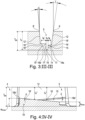
Fig. 3 einen Schnitt entlang der Linie III-III derFig. 2 und -
Fig. 4 einen Schnitt entlang der Linie IV-IV derFig. 2 . - Gemäß der Erfindung ausgeführte Fahrzeugluftreifen sind Reifen für Kraftfahrzeuge, insbesondere für mehrspurige Kraftfahrzeuge, bevorzugt für Personenkraftwagen (PKWs), Vans (Transporter) oder SUVs, sowie vorzugsweise Reifen in Radialbauart für Felgen mit einem ganzzahligen Felgendurchmesser von 13 bis 24 Zoll.
-
Fig. 1 zeigt eine Draufsicht auf einen Ausschnitt eines Laufstreifens eines Fahrzeugluftreifens. Die Reifenäquatorialebene ist durch eine Linie A-A und der eine seitliche Rand der Bodenaufstandsfläche des Laufstreifens ist durch eine Linie L gekennzeichnet. Die Bodenaufstandsfläche entspricht dem statisch ermittelten Footprint (ermittelt mit einem auf einer Normfelge montierten Reifen, Last bei 70 % der maximalen Tragfähigkeit, Innendruck 85 % des Normdrucks, gemäß ETRTO-Standards) und weist in axialer Richtung eine Breite B auf (inFig. 1 ist B/2 eingezeichnet). Der Laufstreifen weist eine laufrichtungsgebundene Profilierung auf, wobei der Fahrzeugluftreifen derart am Fahrzeug zu montieren ist, dass er die durch den Pfeil R angedeutete Abrollrichtung bei Vorwärtsfahrt aufweist. - Der Laufstreifen weist im gezeigten Laufstreifenausschnitt einen schulterseitigen Profilblock 1, einen von der Reifenäquatorialebene (Linie A-A) beabstandeten, halbmittigen Profilblock 2, welcher dem schulterseitigen Profilblock 1 zugeordnet und zu diesem benachbart ist, und einen von der Reifenäquatorialebene (Linie A-A) insbesondere geschnittenen, mittigen Profilblock 3 auf. Über den Umfang des Laufstreifens ist jeweils eine Vielzahl von Profilblöcken 1, 2, 3 vorgesehen, wobei die schulterseitigen Profilblöcke 1 eine in Umfangsrichtung umlaufende schulterseitige Profilblockreihe 1' bilden. Die in Umfangsrichtung zu den Profilblöcken 1, 2, 3 benachbart ausgebildeten Profiblöcke sind in
Fig. 1 lediglich angedeutet. - Die Profilblöcke 1, 2 sind in jeder Umfangsrichtung jeweils gemeinsam von einer Schrägrille 4 begrenzt (Schrägrillen 4 lediglich angedeutet), wobei die Schrägrillen 4, in Draufsicht betrachtet, bezüglich der Umfangsrichtung gleichsinnig zueinander geneigt verlaufen und beim Abrollen des Reifens bei Vorwärtsfahrt (Pfeil R) zuerst mit ihren laufstreifeninnenseitigen Enden in die Bodenaufstandsfläche eintreten. Die Schrägrillen 4 weisen jeweils eine in Draufsicht dem Rillenverlauf folgende, zweifach geknickte Rillenmittellinie mSR auf, verlaufen - in Draufsicht betrachtet und bezogen auf eine die Enden der zugehörigen Rillenmittellinie mSR innerhalb der Bodenaufstandsfläche verbindende gerade Hilfslinie h1 - zur Umfangsrichtung unter einem Winkel α von 40° bis 80°, sind in radialer Richtung auf die jeweils vorgesehene Profiltiefe TSR (
Fig. 3, Fig. 4 ) von üblicherweise 6,5 mm bis 12,0 mm ausgeführt und weisen eine in Draufsicht senkrecht zur Rillenmittellinie mSR an der Laufstreifenperipherie gemessene, in Richtung Laufstreifenrand zunehmende Breite BSR von 3,0 mm bis 15,0 mm auf. Die Winkel α der Schrägrillen 4 können übereinstimmen oder um bis zu 10° voneinander abweichen. - Zwischen in Umfangsrichtung benachbarten Schrägrillen 4 ist eine den schulterseitigen Profilblock 1 vom halbmittigen Profilblock 2 trennende, weiter laufstreifenaußenseitig befindliche Rille 5 und eine den halbmittigen Profilblock 2 vom mittigen Profilblock 3 trennende, weiter laufstreifeninnenseitig befindliche Rille 6 ausgebildet. Die Rille 6 verläuft, in Draufsicht betrachtet, gerade sowie bezüglich der Umfangsrichtung gegensinnig zu den Schrägrillen 4 geneigt, weist an der Laufstreifenperipherie eine in Draufsicht senkrecht zu ihrer Erstreckungsrichtung ermittelte Breite von 2,0 mm bis 6,0 mm und in radialer Richtung eine maximale Tiefe (Tiefe an der tiefsten Stelle) von 70% bis 100% der Profiltiefe TSR (
Fig. 3, Fig. 4 ) auf. - Die Profilblöcke 1, 2 sind jeweils entlang der Längserstreckung der Schrägrillen 4 langgestreckt, wobei der schulterseitige Profilblock 1 mit vier ihn in seiner Längserstreckung innerhalb der Bodenaufstandsfläche durchquerenden und in die Rille 5 einmündenden Einschnitten 7 und der halbmittige Profilblock 2 mit vier ihn in seiner Längserstreckung durchquerenden und in die Rillen 5, 6 einmündenden Einschnitten 8 versehen ist. Die Einschnitte 7, 8 weisen jeweils eine Breite von 0,4 mm bis 1,6 mm, insbesondere von bis zu 1,2 mm, sowie in radialer Richtung eine maximale Tiefe von 70% bis 100% der Profiltiefe auf und verleihen den Profilblöcken 1, 2 jeweils Blocksegmente 1a (Profilblock 1), 2a (Profilblock 2). Gemäß
Fig. 2 ist die Rille 5 an der Laufstreifenperipherie durch zwei in Draufsicht gerade und parallel zueinander verlaufende Rillenkanten 9, 9' - eine am jeweiligen schulterseitigen Profilblock 1 ausgebildete, laufstreifenaußenseitige Rillenkante 9 und eine am jeweiligen halbmittigen Profilblock 2 ausgebildete, laufstreifeninnenseitige Rillenkante 9' - begrenzt, wobei die Rille 5, in Draufsicht betrachtet, eine dem Rillenverlauf folgende, übereinstimmend zu den Rillenkanten 9, 9' beabstandete Mittellinie mR aufweist und ferner gerade, bezüglich der Umfangsrichtung gegensinnig zu den Schrägrillen 4 geneigt sowie bezogen auf die Mittellinie mR zur Umfangrichtung unter einem Winkel β von 15° bis 40°, insbesondere von 18° bis 35°, verläuft. Die Rille 5 weist ein an der einen angrenzenden Schrägrille 4 liegendes, beim Abrollen des Reifens bei Vorwärtsfahrt (Pfeil R) zuerst in den Untergrund eintretendes, weiter laufstreifenaußenseitig befindliches, einlaufendes Rillenende 10 und ein an der anderen angrenzenden Schrägrille 4 liegendes, weiter laufstreifeninnenseitig befindliches, auslaufendes Rillenende 11 auf. Das Rillende 10 weist - gegenüber dem Rillenende 11 - zur Reifenäquatorialebene (Linie A-A,Fig. 1 ) einen größeren in axialer Richtung ermittelten, auf das jeweilige Ende der Mittellinie mR bezogenen Abstand auf. Die Rille 5 weist darüber hinaus eine in Draufsicht senkrecht zur Mittellinie mR sowie zwischen den Rillenkanten 9, 9' ermittelte konstante Breite bR von 3,0 mm bis 10,0 mm, eine in radialer Richtung ermittelte, maximale Tiefe tR (Tiefe an der tiefsten Stelle,Fig. 3 ) von 65% bis 100% der Profiltiefe TSR (Fig. 3, Fig. 4 ), insbesondere von mindestes 70% der Profiltiefe, besonders bevorzugt mindestens 90% der Profiltiefe TSR und höchstens der um 0,1 mm verringerten Profiltiefe TSR, und - in Draufsicht betrachtet und jeweils bezogen auf einen mittig auf ihrer Mittellinie mR liegenden Punkt PR - zum nächstliegenden seitlichen Rand der Bodenaufstandsfläche (Fig. 1 : rechte Linie L) einen an der Laufstreifenperipherie in axialer Richtung ermittelten Abstand aR (Fig. 1 ) von 10% bis 35%, insbesondere von bis zu 25%, bevorzugt von 15% bis 20%, der Breite B (Fig. 1 ) der Bodenaufstandsfläche auf. - Gemäß
Fig. 2 undFig. 3 weist die Rille 5 eine an die Rillenkante 9 anschließende Rillenflanke 12, eine an die Rillenkante 9' anschließende Rillenflanke 12', einen Rillengrund 13 (Fig. 2 ) und einen einschnittartigen Rillenpfad 14 auf. - Gemäß
Fig. 3 verlaufen die Rillenflanken 12, 12', im in Draufsicht senkrecht zur Mittellinie mR ausgerichteten Querschnitt betrachtet (vergl. Lage der Linie III-III inFig. 2 ), gerade sowie zur radialen Richtung unter einem konstanten Winkel γ (Rillenflanke 12), γ' (Rillenflanke 12') von jeweils 0° bis 12°, insbesondere von jeweils 2° bis 8°, wobei der Winkel γ vorzugsweise um 2° bis 6° größer ist als der Winkel γ'. - Wie
Fig. 2 zeigt, verläuft der Rillenpfad 14, in Draufsicht betrachtet, gerade sowie schräg durch die Rille 5 hindurch und mündet daher in die Schrägrillen 4 ein, wobei der Rillenpfad 14 den Rillengrund 13 teilt sowie, in Draufsicht betrachtet, die Mittellinie mR einmal passiert. - Wie
Fig. 2 in Verbindung mitFig. 4 zeigt, befindet sich in der Rille 5 eine an der Rillenflanke 12 sowie entlang der einen Seite des Rillenpfads 14 (Fig. 2 ) ausgebildete, keilförmige Grundanhebung 15 und eine an der Rillenflanke 12' (inFig. 4 nicht sichtbar) sowie entlang der anderen Seite des Rillenpfads 14 (Fig. 2 ) ausgebildete, keilförmige Grundanhebung 15`, sodass die Grundanhebung 15 von der Grundanhebung 15' durch den Rillenpfad 14 getrennt ist (Fig. 2 ). Der Rillenpfad 14 verläuft daher zwischen der Grundanhebung 15 und der Grundanhebung 15' (Fig. 2 ,Fig. 3 ). - Gemäß
Fig. 2 sind die Grundanhebungen 15, 15', in Draufsicht betrachtet, bezüglich des Punkts PR punktsymmetrisch zueinander ausgeführt, sodass die eine der Grundanhebungen 15, 15' durch eine 180°-Drehung um eine in radialer Richtung durch den Punkt PR verlaufende Achse auf die jeweils andere Grundanhebung 15, 15' abbildbar ist. - Wie
Fig. 2 in Kombination mitFig. 3 zeigt, sind die Grundanhebungen 15, 15' in radialer Richtung jeweils durch eine in Draufsicht (Fig. 2 ) in Erstreckungsrichtung der Rille 5 langgezogene, rechtwinkelig-dreieckige Außenfläche 16 (Grundanhebung 15), 16' (Grundanhebung 15') und zum Rillenpfad 14 jeweils durch eine Seitenfläche 17 (Grundanhebung 15,Fig. 3 ), 17' (Grundanhebung 15`,Fig. 3 ) begrenzt, wobei die Außenflächen 16, 16' gemeinsam den Rillengrund 13 (Fig. 2 ) der Rille 5 bilden. - Gemäß
Fig. 2 ist die Schrägstellung des Rillenpfads 14 relativ zur Rille 5 derart, dass der Rillenpfad 14 relativ zur Umfangsrichtung weniger stark geneigt ist als die Rille 5, wodurch die Außenfläche 16 der Grundanhebung 15 in Richtung auslaufendes Rillenende 11 und die Außenfläche 16' der Grundanhebung 15' in Richtung einlaufendes Rillenende 10 ausläuft. - Die Außenfläche 16, 16' weist eine die Dreieckbasis bildende, entlang des Rillenpfads 14 sowie in Draufsicht gerade verlaufende Begrenzungskante 16a (Außenfläche 16), 16a` (Außenfläche 16') auf. Die Außenflächen 16 weist ferner am einlaufenden Rillende 10 eine an die Begrenzungskante 16a anschließende, an der jeweiligen Querrille 4 liegende, parallel zur Laufstreifenperipherie verlaufende Begrenzungskante 16b auf. Die Außenfläche 16' weist ferner am auslaufenden Rillenende 11 eine an die Begrenzungskante 16a` anschließende, an der entsprechenden Querrille 4 liegende, parallel zur Laufstreifenperipherie verlaufende Begrenzungskante 16b` auf.
- Die Außenfläche 16, 16' erscheint gemäß
Fig. 3 , in in Draufsicht senkrecht zur Mittellinie mR verlaufenden Querschnitten betrachtet (vergl. Lage der Linie III-III inFig. 2 ), als gerade und parallel zur Laufstreifenperipherie verlaufende Linie und weist, in diesen Querschnitten betrachtet, eine parallel zur Laufstreifenperipherie gemessene Breite bA (Außenfläche 16), bA' (Außenfläche 16') auf, wobei die Breite bA, bA' gemäßFig. 2 - entsprechend der Dreieckform der Außenfläche 16, 16' - ausgehend von der Begrenzungskante 16b, 16b` entlang der jeweilige Begrenzungskante 16a, 16a` kontinuierlich (also gleichmäßig) abnimmt. Die Größen der Breite bA, bA' ändern sich daher über die in Draufsicht vorliegende Längserstreckung der Rille 5 zueinander entgegengesetzt. - Gemäß
Fig. 4 ist die Außenfläche 16, 16', in in Draufsicht parallel zur Mittellinie mR verlaufenden Längsschnitten betrachtet (vergl. Lage der Linie IV-IV inFig. 2 ), relativ zur Laufstreifenperipherie unter einem konstanten Winkel δ (Außenfläche 16), δ' (Außenfläche 16') geneigt, wobei die Neigung derart ist, dass die Außenfläche 16, 16' ausgehend von der jeweiligen Begrenzungskante 16b, 16b` über die Erstreckung der jeweiligen Begrenzungskante 16a, 16a` (Fig. 2 ) radial nach Innen abfällt. Die Rille 5 weist somit im Bereich der Außenfläche 16, 16' eine in radialer Richtung ermittelte Tiefe tR* auf, welche ausgehend von der jeweiligen Begrenzungskante 16b, 16b` über die Erstreckung der jeweiligen Begrenzungskante 16a, 16a` (Fig. 2 ) - und somit mit abnehmender Breite bA (vergl.Fig. 2 ) - kontinuierlich zunimmt. Die Außenfläche 16, 16' sowie die Begrenzungskante 16a, 16a` (Fig. 2 ) weisen jeweils an ihren an der Begrenzungskante 16b, 16b` liegenden Ende zum Niveau der Profiltiefe TSR ihren größten Abstand aRmax von 10% bis 90%, insbesondere von 15% bis 70%, bevorzugt von 20% bis 50%, der Profiltiefe TSR und am der Begrenzungskante 16b, 16b` abgewandten Ende zum Niveau der Profiltiefe TSR ihren kleinsten Abstand aRmin von bis zu 60%, bevorzugt von bis zu 50%, des größten Abstands aRmax auf. - Zwischen den Rillenflanken 12, 12' und den Außenflächen 16, 16' der Grundanhebung 15, 15' ist jeweils eine Übergangsrundung 18, 18' (
Fig. 2 ,Fig. 3 ) ausgebildet, welche gemäßFig. 3 , im in Draufsicht senkrecht zur Mittellinie mR verlaufenden Querschnitt betrachtet, tangential an die jeweilige Außenfläche 16, 16' und tangential an die jeweilige Rillenflanke 12, 12' anschließt. - Wie
Fig. 2 in Kombination mitFig. 3 zeigt, ist der Rillenpfad 14 durch die bereits erwähnten, an den Grundanhebungen 15, 15' ausgebildeten Seitenflächen 17, 17' (Fig. 3 ) und einen zwischen den Seitenflächen 17, 17' verlaufenden Rillengrund 19 begrenzt. GemäßFig. 2 weist der Rillenpfad 14 eine in Draufsicht seinem Verlauf folgende, übereinstimmend zu den Begrenzungskanten 16a, 16a` beabstandete, gerade verlaufende Mittellinie mP auf, welche - bezüglich der Umfangsrichtung gleichsinnig zur Mittellinie mR der Rille 5 geneigt ist. Der Rillenpfad 14 verläuft - bezogen auf die Mittellinie mP - zur Umfangsrichtung unter einem Winkel ε, welcher kleiner ist als der Winkel β der Rille 5, wobei der Winkel ε derart auf den Winkel β abgestimmt ist, dass - wie bereits erwähnt - die Außenflächen 16, 16' entlang der Begrenzungskanten 16a, 16a` auslaufen. Der Rillenpfad 14 verläuft auf der bereits erwähnten maximale Tiefe tR (Fig. 3 ) und weist eine in Draufsicht senkrecht zur Mittellinie mP ermittelte auf die Begrenzungskanten 16a, 16a` bezogene konstante Breite bp (Fig. 3 ) von 0,5 mm bis 1,5 mm, insbesondere von 0,8 mm bis 1,2 mm, auf, wobei sich die Breite bP, im in Draufsicht senkrecht zur Mittellinie mP verlaufenden Querschnitt betrachtet (vergl. Lage der Linie III-III inFig. 2 ), auf zwei in radialer Richtung durch die Begrenzungskanten 16a, 16a` verlaufende Linien bezieht. GemäßFig. 3 verlaufen die Seitenflächen 17, 17', im zuletzt erwähnten Querschnitt betrachtet, gerade sowie in radialer Richtung oder zu dieser unter einem Winkel von bis zu 2°. Der Rillengrund 19 verläuft, im zuletzt erwähnten Querschnitt betrachtet, U-förmig, und ist symmetrisch bezüglich der Mittellinie mP (Fig. 2 ) ausgeführt. - Die Erfindung ist auf das beschriebene Ausführungsbeispiel nicht beschränkt.
- Insbesondere muss der Laufstreifen nicht laufrichtungsgebunden ausgeführt sein.
- Die Schrägrillen können durchgehend gebogen oder gerade verlaufen. Zwischen in Umfangsrichtung aufeinanderfolgenden Schrägrillen verläuft zumindest eine erfindungsgemäß gestaltete Rille.
- Die zwischen den Schrägrillen verlaufenden Rillen, in welchen die Grundanhebungen und der Rillenpfad ausgebildet sind, können beliebige Profilblöcke voneinander trennen. Bevorzugter Weise sind diese Rillen in jeder Laufstreifenhälfte vorgesehen. Die Rillen können auch in Umfangsrichtung oder bezüglich der Umfangsrichtung gleichsinnig zu den Schrägrillen geneigt verlaufen.
- Die Außenflächen der Grundanhebungen müssen nicht dreieckig ausführt sein.
- Der Rillenpfad kann, in Draufsicht betrachtet, insbesondere durchgehend gebogen (bogenförmig) verlaufen.
-
- 1
- schulterseitiger Profilblock
- 1
- schulterseitige Profilblockreihe
- 1a
- Blocksegment
- 2
- halbmittiger Profilblock
- 2a
- Blocksegment
- 3
- mittiger Profilblock
- 4
- Schrägrille
- 5
- Rille
- 6
- Rille
- 7
- Einschnitt
- 8
- Einschnitt
- 9
- Rillenkante
- 9
- Rillenkante
- 10
- einlaufendes Rillenende
- 11
- auslaufendes Rillenende
- 12, 12
- Rillenflanke
- 13
- Rillengrund
- 14
- Rillenpfad
- 15, 15
- Grundanhebung
- 16, 16
- Außenfläche
- 16a, 16a
- Begrenzungskante
- 16b, 16b
- Begrenzungskante
- 17, 17
- Seitenfläche
- 18, 18`
- Übergangsrundung
- 19
- Rillengrund
- A-A
- Linie (Reifenäquatorialebene)
- aR
- Abstand
- aRmax
- größter Abstand
- aRmin
- kleinster Abstand
- B, BSR, bA, bA', bP, bR
- Breite
- h1
- Hilfslinie
- L
- Linie (seitlicher Rand der Bodenaufstandsfläche)
- mP
- Mittellinie
- mSR
- Rillenmittellinie
- mR
- Mittellinie
- PR
- Punkt
- R
- Pfeil (Abrollrichtung)
- tR
- maximale Tiefe
- tR
- Tiefe
- TSR
- Profiltiefe
- Z2
- Detail
- α, β, γ, γ', δ, δ', ε
- Winkel
Claims (15)
- Fahrzeugluftreifen mit einem Laufstreifen mit Profilblöcken (1, 2, 3), welche von auf Profiltiefe (TSR) reichenden Schrägrillen (4) und von Rillen (5, 6) begrenzt sind, welche Rillen (5, 6) zwischen in Umfangsrichtung aufeinanderfolgenden Schrägrillen (4) ausgebildet sind, insbesondere bezüglich der Umfangsrichtung gegensinnig zu den Schrägrillen (4) geneigt verlaufen und an den Schrägrillen (4) Rillenenden (10, 11) aufweisen und zu welchen Rillen (5) gehören, die jeweils eine Breite (bR) von 3,0 mm bis 10,0 mm, eine maximale Tiefe (tR) von 65% bis 100% der Profiltiefe (TSR), von der Laufstreifenperipherie ausgehende Rillenflanken (12, 12') und einen in ihrer maximalen Tiefe (tR) verlaufenden, in die Schrägrillen (4) einmündenden Rillenpfad (14) aufweisen, welcher sich in Draufsicht schräg durch die jeweilige Rille (5) hindurcherstreckt und zwischen einer entlang der einen Rillenflanke (12) ausgebildeten Grundanhebung (15) und einer entlang der anderen Rillenflanke (12') ausgebildete Grundanhebung (15') verläuft, wobei jede Grundanhebung (15, 15') in radialer Richtung durch eine Außenfläche (16, 16') begrenzt ist, welche, im in Draufsicht senkrecht zur Mittellinie (mR) der Rille (5) verlaufenden Querschnitt betrachtet, parallel zur Laufstreifenperipherie verläuft und eine von dem einen Rillenende (10) zum anderen Rillenende (11) kontinuierlich abnehmende Breite (bA, bA') aufweist,
dadurch gekennzeichnet,
dass die Außenfläche (16, 16') jeder Grundanhebung (15, 15'), in Längsschnitten der Rille (5) betrachtet, derart relativ zur Laufstreifenperipherie unter einem Winkel (δ, δ') geneigt verläuft, dass die Rille (5) im Bereich der Außenfläche (16, 16') eine in radialer Richtung ermittelte Tiefe (tR*) aufweist, welche mit abnehmender Breite (bA, bA') der Außenfläche (16, 16') kontinuierlich zunimmt. - Fahrzeugluftreifen nach Anspruch 1, dadurch gekennzeichnet, dass die Außenfläche (16, 16') jeder Grundanhebung (15, 15') an jenem Rillenende (10, 11), an welchem die Tiefe (tR*) der Rille (5) am kleinsten ist, zum Niveau der Profiltiefe (TSR) einen in radialer Richtung ermittelten größten Abstand (aRmax) von 10% bis 90%, insbesondere von 15% bis 70%, bevorzugt von 20% bis 50%, der Profiltiefe (TSR) aufweist.
- Fahrzeugluftreifen nach Anspruch 2, dadurch gekennzeichnet, dass die Außenfläche (16, 16') jeder Grundanhebung (15, 15') an jenem Rillenende (10, 11), an welchem die Tiefe (tR*) der Rille (5) am größten ist, zum Niveau der Profiltiefe (TSR) einen in radialer Richtung ermittelten kleinsten Abstand (aRmin) von bis zu 60%, bevorzugt von bis zu 50%, des größten Abstands (aRmax) aufweist.
- Fahrzeugluftreifen nach einem der Ansprüche 1 bis 3, dadurch gekennzeichnet, dass der Rillenpfad (14), in Draufsicht betrachtet, gerade verläuft.
- Fahrzeugluftreifen nach Anspruch 4, dadurch gekennzeichnet, dass sich der Rillenpfad (14) derart schräg durch die Rille (5) hindurcherstreckt, dass die Außenfläche (16, 16') jeder Grundanhebung (15, 15'), in Draufsicht betrachtet, die Form eines rechtwinkeligen Dreieckes aufweist.
- Fahrzeugluftreifen nach einem der Ansprüche 1 bis 5, dadurch gekennzeichnet, dass die Rille (5) an der Laufstreifenperipherie eine laufstreifenaußenseitige Rillenkante (9) und eine laufstreifeninnenseitige Rillenkante (8) sowie ferner ein laufstreifenaußenseitiges Rillenende (10) und ein laufstreifeninnenseitiges Rillende (11) aufweist,- wobei die Breite (bA) der Außenfläche (16) der Grundanhebung (15), welche entlang der von der laufstreifenaußenseitigen Rillenkante (9) ausgehenden Rillenflanke (12) ausgebildet ist, vom laufstreifenaußenseitigen Rillenende (10) zum laufstreifeninnenseitigen Rillende (11) abnimmt und- wobei die Breite (bA') der Außenfläche (16') der Grundanhebung (15`), welche entlang der von der laufstreifeninnenseitigen Rillenkante (9') ausgehenden Rillenflanke (12') ausgebildet ist, vom laufstreifeninnenseitigen Rillenende (11) zum laufstreifenaußenseitigen Rillenende (10) abnimmt.
- Fahrzeugluftreifen nach Anspruch 6, dadurch gekennzeichnet, dass der Laufstreifen laufrichtungsgebunden ausgeführt ist, wobei das laufstreifenaußenseitige Rillenende (10) ein beim Abrollen des Reifens bei Vorwärtsfahrt (Pfeil R) zuerst in den Untergrund eintretendes, einlaufendes Rillenende (10) und das laufstreifeninnenseitige Rillenende (11) ein auslaufendes Rillenende (11) ist.
- Fahrzeugluftreifen nach einem der Ansprüche 1 bis 7, dadurch gekennzeichnet, dass die Rille (5) und der Rillenpfad (14), in Draufsicht betrachtet, bezogen auf ihre Mittellinien (mR, mP), gerade und bezüglich der Umfangsrichtung gleichsinnig zueinander geneigt verlaufen.
- Fahrzeugluftreifen nach Anspruch 8, dadurch gekennzeichnet, dass die Rille (5) und der Rillenpfad (14), in Draufsicht betrachtet, bezogen auf ihre Mittellinien (mR, mP), zur Umfangsrichtung jeweils unter einem Winkel (β, ε) verlaufen, wobei der Winkel (ε), unter welchem der Rillenpfad (14) zur Umfangsrichtung verläuft, kleiner ist als der Winkel (β), unter welchem die Rille (5) zur Umfangsrichtung verläuft.
- Fahrzeugluftreifen nach Anspruch 9, dadurch gekennzeichnet, dass der Winkel (β), unter welchem die Rille (5) zur Umfangsrichtung verläuft, 15° bis 40°, insbesondere von 18° bis 35°, beträgt.
- Fahrzeugluftreifen nach einem der Ansprüche 1 bis 10, dadurch gekennzeichnet, dass die Außenfläche (16, 16') jeder Grundanhebung (15, 15') bis zum Rillenpfad (14) reicht und an diesem eine Begrenzungskante (16a, 16a') aufweist, entlang welcher die Breite (bA, bA') der Außenfläche (16, 16') kontinuierlich abnimmt.
- Fahrzeugluftreifen nach Anspruch 11, dadurch gekennzeichnet, dass der Rillenpfad (14) eine in Draufsicht senkrecht zu seiner Mittellinie (mp) ermittelte, auf die Begrenzungskanten (16a, 16a`) bezogene konstante Breite (bP) von 0,5 mm bis 1,5 mm, insbesondere von 0,8 mm bis 1,2 mm, aufweist.
- Fahrzeugluftreifen nach einem der Ansprüche 1 bis 12, dadurch gekennzeichnet, dass die Grundanhebungen (15, 15'), in Draufsicht betrachtet, bezüglich des Mittelpunkts (PR) der Mittellinie (mP) des Rillenpfads (14) punktsymmetrisch ausgeführt sind.
- Fahrzeugluftreifen nach einem der Ansprüche 1 bis 13, dadurch gekennzeichnet, dass zu den von den Rillen (5) begrenzten Profilblöcken (1, 2, 3) schulterseitige Profilblöcke (1) gehören, wobei die schulterseitigen Profilblöcke (1) vorzugsweise mit in Draufsicht bezüglich der Umfangsrichtung gleichsinnig zu den Schrägrillen (4) geneigt verlaufenden, in die Rillen (5) einmündenden Einschnitten (7) mit einer Breite von 0,4 mm bis 1,6 mm, insbesondere von bis zu 1,2 mm, und einer maximalen Tiefe von 70% bis 100% der Profiltiefe versehen sind.
- Fahrzeugluftreifen nach einem der Ansprüche 1 bis 14, dadurch gekennzeichnet, dass zu den von den Rillen (5) begrenzten Profilblöcken (1, 2, 3) Profilblöcke (1, 2) gehören, welche in jeder Umfangsrichtung gemeinsam von einer der Schrägrillen (4) begrenzt sind, wobei zwischen den Schrägrillen (4) eine der Rillen (5) verläuft, wobei die Profilblöcke (1, 2) vorzugsweise mit in Draufsicht bezüglich der Umfangsrichtung gleichsinnig zu den Schrägrillen (4) geneigt verlaufenden, in die Rillen (5) einmündenden Einschnitten (7) mit einer Breite von 0,4 mm bis 1,6 mm, insbesondere von bis zu 1,2 mm, und einer maximalen Tiefe von 70% bis 100% der Profiltiefe versehen sind.
Applications Claiming Priority (1)
| Application Number | Priority Date | Filing Date | Title |
|---|---|---|---|
| DE102022211346.2A DE102022211346A1 (de) | 2022-10-26 | 2022-10-26 | Fahrzeugluftreifen |
Publications (2)
| Publication Number | Publication Date |
|---|---|
| EP4360914A1 true EP4360914A1 (de) | 2024-05-01 |
| EP4360914B1 EP4360914B1 (de) | 2025-03-26 |
Family
ID=88147137
Family Applications (1)
| Application Number | Title | Priority Date | Filing Date |
|---|---|---|---|
| EP23198970.8A Active EP4360914B1 (de) | 2022-10-26 | 2023-09-22 | Fahrzeugluftreifen |
Country Status (3)
| Country | Link |
|---|---|
| EP (1) | EP4360914B1 (de) |
| DE (1) | DE102022211346A1 (de) |
| FI (1) | FI4360914T3 (de) |
Citations (7)
| Publication number | Priority date | Publication date | Assignee | Title |
|---|---|---|---|---|
| JP3720519B2 (ja) * | 1997-03-26 | 2005-11-30 | 株式会社ブリヂストン | 荒れた路面を走行する乗用車乃至ライト・トラック用空気入りラジアル・タイヤ |
| EP2501561B1 (de) | 2009-11-16 | 2013-07-24 | Continental Reifen Deutschland GmbH | Laufstreifenprofil eines fahrzeugreifens |
| FR3026347A1 (fr) * | 2014-09-30 | 2016-04-01 | Michelin & Cie | Pneumatique comportant une bande de roulement comprenant un element en protuberance dans une rainure transversale |
| EP3551476A1 (de) * | 2016-12-07 | 2019-10-16 | Continental Reifen Deutschland GmbH | Fahrzeugluftreifen |
| EP3589500A1 (de) * | 2017-02-28 | 2020-01-08 | Continental Reifen Deutschland GmbH | Fahrzeugluftreifen |
| US20200039298A1 (en) * | 2017-03-30 | 2020-02-06 | The Yokohama Rubber Co., Ltd. | Pneumatic Tire |
| FR3111292A1 (fr) * | 2020-06-10 | 2021-12-17 | Compagnie Generale Des Etablissements Michelin | Bande de roulement de pneumatique pour un véhicule poids lourd avec une résistance aux agressions améliorée |
-
2022
- 2022-10-26 DE DE102022211346.2A patent/DE102022211346A1/de active Pending
-
2023
- 2023-09-22 EP EP23198970.8A patent/EP4360914B1/de active Active
- 2023-09-22 FI FIEP23198970.8T patent/FI4360914T3/fi active
Patent Citations (7)
| Publication number | Priority date | Publication date | Assignee | Title |
|---|---|---|---|---|
| JP3720519B2 (ja) * | 1997-03-26 | 2005-11-30 | 株式会社ブリヂストン | 荒れた路面を走行する乗用車乃至ライト・トラック用空気入りラジアル・タイヤ |
| EP2501561B1 (de) | 2009-11-16 | 2013-07-24 | Continental Reifen Deutschland GmbH | Laufstreifenprofil eines fahrzeugreifens |
| FR3026347A1 (fr) * | 2014-09-30 | 2016-04-01 | Michelin & Cie | Pneumatique comportant une bande de roulement comprenant un element en protuberance dans une rainure transversale |
| EP3551476A1 (de) * | 2016-12-07 | 2019-10-16 | Continental Reifen Deutschland GmbH | Fahrzeugluftreifen |
| EP3589500A1 (de) * | 2017-02-28 | 2020-01-08 | Continental Reifen Deutschland GmbH | Fahrzeugluftreifen |
| US20200039298A1 (en) * | 2017-03-30 | 2020-02-06 | The Yokohama Rubber Co., Ltd. | Pneumatic Tire |
| FR3111292A1 (fr) * | 2020-06-10 | 2021-12-17 | Compagnie Generale Des Etablissements Michelin | Bande de roulement de pneumatique pour un véhicule poids lourd avec une résistance aux agressions améliorée |
Also Published As
| Publication number | Publication date |
|---|---|
| EP4360914B1 (de) | 2025-03-26 |
| FI4360914T3 (fi) | 2025-07-16 |
| DE102022211346A1 (de) | 2024-05-02 |
Similar Documents
| Publication | Publication Date | Title |
|---|---|---|
| EP3589501B1 (de) | Fahrzeugluftreifen | |
| EP3589500B1 (de) | Fahrzeugluftreifen | |
| EP4244080B1 (de) | Fahrzeugluftreifen | |
| EP3256334B1 (de) | Fahrzeugluftreifen | |
| EP1238827B1 (de) | Reifenprofil | |
| EP3300926B1 (de) | Fahrzeugluftreifen | |
| EP3009275B1 (de) | Fahrzeugluftreifen | |
| WO2019115036A1 (de) | Nutzfahrzeugreifen | |
| EP3277523B1 (de) | Fahrzeugluftreifen | |
| EP4577416A1 (de) | Fahrzeugluftreifen | |
| EP2138329B1 (de) | Laufflächenprofil für einen Fahrzeugluftreifen | |
| EP2138327A1 (de) | Laufflächenprofil für einen Fahrzeugluftreifen | |
| EP4360914B1 (de) | Fahrzeugluftreifen | |
| WO2024200185A1 (de) | Fahrzeugluftreifen | |
| EP4244079B1 (de) | Fahrzeugluftreifen | |
| EP2138328B1 (de) | Fahrzeugluftreifen | |
| EP3300925B1 (de) | Fahrzeugluftreifen | |
| WO2024041706A1 (de) | Fahrzeugluftreifen | |
| EP3686034B1 (de) | Fahrzeugluftreifen | |
| EP4360913B1 (de) | Fahrzeugluftreifen | |
| EP4301609B1 (de) | Fahrzeugluftreifen | |
| EP4628328A1 (de) | Fahrzeugreifen | |
| WO2019042596A1 (de) | Fahrzeugluftreifen | |
| EP3450216B1 (de) | Fahrzeugluftreifen | |
| EP3418076A1 (de) | Fahrzeugluftreifen |
Legal Events
| Date | Code | Title | Description |
|---|---|---|---|
| PUAI | Public reference made under article 153(3) epc to a published international application that has entered the european phase |
Free format text: ORIGINAL CODE: 0009012 |
|
| STAA | Information on the status of an ep patent application or granted ep patent |
Free format text: STATUS: THE APPLICATION HAS BEEN PUBLISHED |
|
| AK | Designated contracting states |
Kind code of ref document: A1 Designated state(s): AL AT BE BG CH CY CZ DE DK EE ES FI FR GB GR HR HU IE IS IT LI LT LU LV MC ME MK MT NL NO PL PT RO RS SE SI SK SM TR |
|
| STAA | Information on the status of an ep patent application or granted ep patent |
Free format text: STATUS: REQUEST FOR EXAMINATION WAS MADE |
|
| 17P | Request for examination filed |
Effective date: 20241104 |
|
| RBV | Designated contracting states (corrected) |
Designated state(s): AL AT BE BG CH CY CZ DE DK EE ES FI FR GB GR HR HU IE IS IT LI LT LU LV MC ME MK MT NL NO PL PT RO RS SE SI SK SM TR |
|
| GRAP | Despatch of communication of intention to grant a patent |
Free format text: ORIGINAL CODE: EPIDOSNIGR1 |
|
| STAA | Information on the status of an ep patent application or granted ep patent |
Free format text: STATUS: GRANT OF PATENT IS INTENDED |
|
| INTG | Intention to grant announced |
Effective date: 20241213 |
|
| GRAS | Grant fee paid |
Free format text: ORIGINAL CODE: EPIDOSNIGR3 |
|
| GRAA | (expected) grant |
Free format text: ORIGINAL CODE: 0009210 |
|
| STAA | Information on the status of an ep patent application or granted ep patent |
Free format text: STATUS: THE PATENT HAS BEEN GRANTED |
|
| P01 | Opt-out of the competence of the unified patent court (upc) registered |
Free format text: CASE NUMBER: APP_4294/2025 Effective date: 20250127 |
|
| AK | Designated contracting states |
Kind code of ref document: B1 Designated state(s): AL AT BE BG CH CY CZ DE DK EE ES FI FR GB GR HR HU IE IS IT LI LT LU LV MC ME MK MT NL NO PL PT RO RS SE SI SK SM TR |
|
| REG | Reference to a national code |
Ref country code: GB Ref legal event code: FG4D Free format text: NOT ENGLISH |
|
| REG | Reference to a national code |
Ref country code: CH Ref legal event code: EP |
|
| REG | Reference to a national code |
Ref country code: DE Ref legal event code: R096 Ref document number: 502023000728 Country of ref document: DE |
|
| REG | Reference to a national code |
Ref country code: IE Ref legal event code: FG4D Free format text: LANGUAGE OF EP DOCUMENT: GERMAN |
|
| PG25 | Lapsed in a contracting state [announced via postgrant information from national office to epo] |
Ref country code: RS Free format text: LAPSE BECAUSE OF FAILURE TO SUBMIT A TRANSLATION OF THE DESCRIPTION OR TO PAY THE FEE WITHIN THE PRESCRIBED TIME-LIMIT Effective date: 20250626 |
|
| REG | Reference to a national code |
Ref country code: LT Ref legal event code: MG9D |
|
| PG25 | Lapsed in a contracting state [announced via postgrant information from national office to epo] |
Ref country code: NO Free format text: LAPSE BECAUSE OF FAILURE TO SUBMIT A TRANSLATION OF THE DESCRIPTION OR TO PAY THE FEE WITHIN THE PRESCRIBED TIME-LIMIT Effective date: 20250626 |
|
| PG25 | Lapsed in a contracting state [announced via postgrant information from national office to epo] |
Ref country code: HR Free format text: LAPSE BECAUSE OF FAILURE TO SUBMIT A TRANSLATION OF THE DESCRIPTION OR TO PAY THE FEE WITHIN THE PRESCRIBED TIME-LIMIT Effective date: 20250326 |
|
| REG | Reference to a national code |
Ref country code: FI Ref legal event code: FGE |
|
| PG25 | Lapsed in a contracting state [announced via postgrant information from national office to epo] |
Ref country code: LV Free format text: LAPSE BECAUSE OF FAILURE TO SUBMIT A TRANSLATION OF THE DESCRIPTION OR TO PAY THE FEE WITHIN THE PRESCRIBED TIME-LIMIT Effective date: 20250326 |
|
| PG25 | Lapsed in a contracting state [announced via postgrant information from national office to epo] |
Ref country code: GR Free format text: LAPSE BECAUSE OF FAILURE TO SUBMIT A TRANSLATION OF THE DESCRIPTION OR TO PAY THE FEE WITHIN THE PRESCRIBED TIME-LIMIT Effective date: 20250627 Ref country code: BG Free format text: LAPSE BECAUSE OF FAILURE TO SUBMIT A TRANSLATION OF THE DESCRIPTION OR TO PAY THE FEE WITHIN THE PRESCRIBED TIME-LIMIT Effective date: 20250326 |
|
| REG | Reference to a national code |
Ref country code: NL Ref legal event code: MP Effective date: 20250326 |
|
| PG25 | Lapsed in a contracting state [announced via postgrant information from national office to epo] |
Ref country code: NL Free format text: LAPSE BECAUSE OF FAILURE TO SUBMIT A TRANSLATION OF THE DESCRIPTION OR TO PAY THE FEE WITHIN THE PRESCRIBED TIME-LIMIT Effective date: 20250326 |
|
| PG25 | Lapsed in a contracting state [announced via postgrant information from national office to epo] |
Ref country code: SE Free format text: LAPSE BECAUSE OF FAILURE TO SUBMIT A TRANSLATION OF THE DESCRIPTION OR TO PAY THE FEE WITHIN THE PRESCRIBED TIME-LIMIT Effective date: 20250326 |
|
| PG25 | Lapsed in a contracting state [announced via postgrant information from national office to epo] |
Ref country code: SM Free format text: LAPSE BECAUSE OF FAILURE TO SUBMIT A TRANSLATION OF THE DESCRIPTION OR TO PAY THE FEE WITHIN THE PRESCRIBED TIME-LIMIT Effective date: 20250326 |
|
| PG25 | Lapsed in a contracting state [announced via postgrant information from national office to epo] |
Ref country code: ES Free format text: LAPSE BECAUSE OF FAILURE TO SUBMIT A TRANSLATION OF THE DESCRIPTION OR TO PAY THE FEE WITHIN THE PRESCRIBED TIME-LIMIT Effective date: 20250326 Ref country code: PT Free format text: LAPSE BECAUSE OF FAILURE TO SUBMIT A TRANSLATION OF THE DESCRIPTION OR TO PAY THE FEE WITHIN THE PRESCRIBED TIME-LIMIT Effective date: 20250728 |
|
| PGFP | Annual fee paid to national office [announced via postgrant information from national office to epo] |
Ref country code: FI Payment date: 20250926 Year of fee payment: 3 |
|
| PGFP | Annual fee paid to national office [announced via postgrant information from national office to epo] |
Ref country code: DE Payment date: 20250930 Year of fee payment: 3 |
|
| PG25 | Lapsed in a contracting state [announced via postgrant information from national office to epo] |
Ref country code: IT Free format text: LAPSE BECAUSE OF FAILURE TO SUBMIT A TRANSLATION OF THE DESCRIPTION OR TO PAY THE FEE WITHIN THE PRESCRIBED TIME-LIMIT Effective date: 20250326 Ref country code: PL Free format text: LAPSE BECAUSE OF FAILURE TO SUBMIT A TRANSLATION OF THE DESCRIPTION OR TO PAY THE FEE WITHIN THE PRESCRIBED TIME-LIMIT Effective date: 20250326 |
|
| PGFP | Annual fee paid to national office [announced via postgrant information from national office to epo] |
Ref country code: FR Payment date: 20250922 Year of fee payment: 3 Ref country code: AT Payment date: 20251020 Year of fee payment: 3 |
|
| PG25 | Lapsed in a contracting state [announced via postgrant information from national office to epo] |
Ref country code: EE Free format text: LAPSE BECAUSE OF FAILURE TO SUBMIT A TRANSLATION OF THE DESCRIPTION OR TO PAY THE FEE WITHIN THE PRESCRIBED TIME-LIMIT Effective date: 20250326 |
|
| PG25 | Lapsed in a contracting state [announced via postgrant information from national office to epo] |
Ref country code: RO Free format text: LAPSE BECAUSE OF FAILURE TO SUBMIT A TRANSLATION OF THE DESCRIPTION OR TO PAY THE FEE WITHIN THE PRESCRIBED TIME-LIMIT Effective date: 20250326 |
|
| PG25 | Lapsed in a contracting state [announced via postgrant information from national office to epo] |
Ref country code: SK Free format text: LAPSE BECAUSE OF FAILURE TO SUBMIT A TRANSLATION OF THE DESCRIPTION OR TO PAY THE FEE WITHIN THE PRESCRIBED TIME-LIMIT Effective date: 20250326 |
|
| PG25 | Lapsed in a contracting state [announced via postgrant information from national office to epo] |
Ref country code: IS Free format text: LAPSE BECAUSE OF FAILURE TO SUBMIT A TRANSLATION OF THE DESCRIPTION OR TO PAY THE FEE WITHIN THE PRESCRIBED TIME-LIMIT Effective date: 20250726 |
|
| REG | Reference to a national code |
Ref country code: DE Ref legal event code: R097 Ref document number: 502023000728 Country of ref document: DE |
|
| PG25 | Lapsed in a contracting state [announced via postgrant information from national office to epo] |
Ref country code: DK Free format text: LAPSE BECAUSE OF FAILURE TO SUBMIT A TRANSLATION OF THE DESCRIPTION OR TO PAY THE FEE WITHIN THE PRESCRIBED TIME-LIMIT Effective date: 20250326 |
|
| PG25 | Lapsed in a contracting state [announced via postgrant information from national office to epo] |
Ref country code: CZ Free format text: LAPSE BECAUSE OF FAILURE TO SUBMIT A TRANSLATION OF THE DESCRIPTION OR TO PAY THE FEE WITHIN THE PRESCRIBED TIME-LIMIT Effective date: 20250326 |
|
| PLBE | No opposition filed within time limit |
Free format text: ORIGINAL CODE: 0009261 |
|
| STAA | Information on the status of an ep patent application or granted ep patent |
Free format text: STATUS: NO OPPOSITION FILED WITHIN TIME LIMIT |
|
| REG | Reference to a national code |
Ref country code: CH Ref legal event code: L10 Free format text: ST27 STATUS EVENT CODE: U-0-0-L10-L00 (AS PROVIDED BY THE NATIONAL OFFICE) Effective date: 20260211 |
|
| 26N | No opposition filed |
Effective date: 20260105 |