EP4360859A1 - Bottle unit and puncture repair kit - Google Patents
Bottle unit and puncture repair kit Download PDFInfo
- Publication number
- EP4360859A1 EP4360859A1 EP23204508.8A EP23204508A EP4360859A1 EP 4360859 A1 EP4360859 A1 EP 4360859A1 EP 23204508 A EP23204508 A EP 23204508A EP 4360859 A1 EP4360859 A1 EP 4360859A1
- Authority
- EP
- European Patent Office
- Prior art keywords
- puncture repair
- opening
- repair liquid
- bottle
- bottle container
- Prior art date
- Legal status (The legal status is an assumption and is not a legal conclusion. Google has not performed a legal analysis and makes no representation as to the accuracy of the status listed.)
- Pending
Links
Images



Classifications
-
- B—PERFORMING OPERATIONS; TRANSPORTING
- B29—WORKING OF PLASTICS; WORKING OF SUBSTANCES IN A PLASTIC STATE IN GENERAL
- B29C—SHAPING OR JOINING OF PLASTICS; SHAPING OF MATERIAL IN A PLASTIC STATE, NOT OTHERWISE PROVIDED FOR; AFTER-TREATMENT OF THE SHAPED PRODUCTS, e.g. REPAIRING
- B29C73/00—Repairing of articles made from plastics or substances in a plastic state, e.g. of articles shaped or produced by using techniques covered by this subclass or subclass B29D
- B29C73/16—Auto-repairing or self-sealing arrangements or agents
- B29C73/166—Devices or methods for introducing sealing compositions into articles
-
- B—PERFORMING OPERATIONS; TRANSPORTING
- B29—WORKING OF PLASTICS; WORKING OF SUBSTANCES IN A PLASTIC STATE IN GENERAL
- B29C—SHAPING OR JOINING OF PLASTICS; SHAPING OF MATERIAL IN A PLASTIC STATE, NOT OTHERWISE PROVIDED FOR; AFTER-TREATMENT OF THE SHAPED PRODUCTS, e.g. REPAIRING
- B29C73/00—Repairing of articles made from plastics or substances in a plastic state, e.g. of articles shaped or produced by using techniques covered by this subclass or subclass B29D
- B29C73/02—Repairing of articles made from plastics or substances in a plastic state, e.g. of articles shaped or produced by using techniques covered by this subclass or subclass B29D using liquid or paste-like material
- B29C73/025—Repairing of articles made from plastics or substances in a plastic state, e.g. of articles shaped or produced by using techniques covered by this subclass or subclass B29D using liquid or paste-like material fed under pressure
-
- B—PERFORMING OPERATIONS; TRANSPORTING
- B29—WORKING OF PLASTICS; WORKING OF SUBSTANCES IN A PLASTIC STATE IN GENERAL
- B29L—INDEXING SCHEME ASSOCIATED WITH SUBCLASS B29C, RELATING TO PARTICULAR ARTICLES
- B29L2030/00—Pneumatic or solid tyres or parts thereof
Definitions
- the present invention relates to a bottle unit and a puncture repair kit to be used for repairing a punctured tire.
- Japanese Laid-Open Patent Publication No. 2017-056662 proposes a puncture repair kit for repairing a punctured tire by sequentially injecting a puncture repair liquid and compressed air into the punctured tire, with the compressed air from a compressor.
- the present invention has been made in view of the above circumstances, and a main object of the present invention is to provide a bottle unit and a puncture repair kit for performing puncture repair in a short time.
- the present invention is directed to a bottle unit for performing filling with a puncture repair liquid and compressed air
- the bottle unit includes a bottle container capable of storing the puncture repair liquid therein, a supply pipe for supplying the compressed air into the bottle container, and a discharge pipe for mixing and discharging the puncture repair liquid and the compressed air from the bottle container.
- the discharge pipe has a first opening opened inside the bottle container, and a second opening opened at a position different from the first opening in a height direction of the bottle container inside the bottle container.
- the bottle unit of the present invention allows puncture repair to be performed in a short time by having the above configuration.
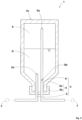
- FIG. 1 is a schematic view of a puncture repair kit 1 of the present embodiment.
- the puncture repair kit 1 is suitably used to fill a punctured tire T with a puncture repair liquid R and compressed air A.
- the puncture repair kit 1 of the present embodiment includes a bottle unit 2, and a compressor 3 for supplying the compressed air A into the bottle unit 2.
- the bottle unit 2 of the present embodiment includes a bottle container 4 capable of storing the puncture repair liquid R therein, a supply pipe 5 for supplying the compressed air A into the bottle container 4, and a discharge pipe 6 for mixing and discharging the puncture repair liquid R and the compressed air A from the bottle container 4.
- the bottle container 4 includes a container body 4a and a cap 4b, for example.
- the supply pipe 5 and the discharge pipe 6 of the present embodiment each provide communication between the outside and inside of the bottle container 4 via the cap 4b.
- the supply pipe 5 has an opening 5a opened inside the bottle container 4, for example.
- the discharge pipe 6 of the present embodiment has a first opening 6a opened inside the bottle container 4, and a second opening 6b opened at a position different from the first opening 6a in a height direction of the bottle container 4 inside the bottle container 4.
- the height direction of the bottle container 4 is a vertical direction in a state in which the bottle container 4 is held when filling with the puncture repair liquid R is performed.
- the discharge pipe 6 allows the puncture repair liquid R and the compressed air A to be mixed thereinside. Accordingly, the bottle unit 2 of the present embodiment can fill the tire T with the puncture repair liquid R and the compressed air A at the same time, and can supply the puncture repair liquid R concentratively to a punctured part with the compressed air A even if the amount of the puncture repair liquid R is small. Therefore, the bottle unit 2 of the present embodiment allows puncture repair to be performed in a short time.
- the bottle container 4 can be held in a first posture in which the first opening 6a is positioned in the puncture repair liquid R and the second opening 6b is positioned outside the puncture repair liquid R.
- FIG. 1 illustrates a state in which the bottle container 4 of the present embodiment is held in the first posture when filling with the puncture repair liquid R is performed.
- the first posture of the present embodiment is a posture in which a bottom portion 4c of the bottle container 4 is directed downward.
- Such a bottle unit 2 can mix the puncture repair liquid R supplied through the first opening 6a and the compressed air A supplied through the second opening 6b, inside the discharge pipe 6, when the tire T is filled with the puncture repair liquid R.
- FIG. 2 is a schematic view of the puncture repair kit 1 when the bottle container 4 is held in a second posture.
- the bottle container 4 of the present embodiment can be held in the second posture in which the first opening 6a is positioned outside the puncture repair liquid R and the second opening 6b is positioned in the puncture repair liquid R when filling with the puncture repair liquid R is performed.
- the second posture of the present embodiment is a posture in which the cap 4b of the bottle container 4 is directed downward.
- Such a bottle unit 2 can mix the compressed air A supplied through the first opening 6a and the puncture repair liquid R supplied through the second opening 6b, inside the discharge pipe 6, when the tire T is filled with the puncture repair liquid R.
- the bottle container 4 can be preferably held in the first posture or the second posture when filling with the puncture repair liquid R is performed.
- the bottle container 4 can be used selectively in the first posture or the second posture according to use conditions thereof or the like, when filling with the puncture repair liquid R is performed.
- the opening 5a is formed at an end portion of the supply pipe 5, for example.
- the opening 5a of the present embodiment is positioned outside the puncture repair liquid R in the first posture, and is positioned in the puncture repair liquid R in the second posture.
- the opening 5a of the present embodiment is formed near the second opening 6b of the discharge pipe 6.
- the opening 5a allows the length of the supply pipe 5 to be shortened, thereby serving to reduce the size of the bottle unit 2.
- the position of the opening 5a is not limited thereto, and may be formed near the first opening 6a of the discharge pipe 6, for example.
- the first opening 6a is preferably formed at an end portion of the discharge pipe 6.
- the first opening 6a of the present embodiment is formed near the bottom portion 4c of the bottle container 4.
- the first opening 6a serves to discharge all the puncture repair liquid R in a short time when filling with the puncture repair liquid R is performed in the first posture.
- this first opening 6a allows the puncture repair liquid R and the compressed air A to be mixed even if the volume of the compressed air A is small, when filling with the puncture repair liquid R is performed in the second posture, thereby serving to reduce the size of the bottle container 4.
- the second opening 6b is preferably formed on a side opposite to the end portion of the discharge pipe 6 in the height direction of the bottle container 4.
- the second opening 6b of the present embodiment is formed near the cap 4b of the bottle container 4.
- the second opening 6b allows the puncture repair liquid R and the compressed air A to be mixed even if the volume of the compressed air A is small, when filling with the puncture repair liquid R is performed in the first posture, thereby serving to reduce the size of the bottle container 4.
- the second opening 6b serves to discharge all the puncture repair liquid R in a short time, when filling with the puncture repair liquid R is performed in the second posture.
- the second opening 6b is at least one hole formed in the side surface of the discharge pipe 6, for example.
- An opening area S2 of the second opening 6b is preferably 0.1 to 0.9 times an opening area S1 of the first opening 6a, and more preferably 0.2 to 0.6 times the opening area S1 of the first opening 6a.
- Such a discharge pipe 6 is suitable to mix the puncture repair liquid R and the compressed air A thereinside and to fill the tire T with a mixture thereof in an aerosolized form.
- the opening area S1 of the first opening 6a represents a cross-sectional area of the inside of the discharge pipe 6, and the opening area S2 of the second opening 6b represents the sum of the opening areas of all the holes.
- FIG. 3 is a schematic view of a puncture repair kit 11 of a second embodiment.
- the puncture repair kit 11 of the second embodiment includes a bottle unit 12 and a compressor 3, similarly to the above-described puncture repair kit 1.
- the bottle unit 12 of the second embodiment includes a bottle container 14 capable of storing a puncture repair liquid R therein, a supply pipe 15 for supplying compressed air A, and a discharge pipe 16 for mixing and discharging the puncture repair liquid R and the compressed air A.
- the bottle container 14 includes a container body 14a and a cap 14b, for example.
- the supply pipe 15 of the second embodiment provides communication between the outside and inside of the bottle container 14 via the cap 14b.
- the discharge pipe 16 of the second embodiment provides communication between the outside and inside of the bottle container 14 via a bottom portion 14c of the container body 14a.
- the supply pipe 15 has an opening 15a opened inside the bottle container 14, for example.
- the discharge pipe 16 of the second embodiment has a first opening 16a opened inside the bottle container 14, and a second opening 16b opened at a position different from the first opening 16a in a height direction of the bottle container 14 inside the bottle container 14.
- the discharge pipe 16 allows the puncture repair liquid R and the compressed air A to be mixed thereinside. Accordingly, the bottle unit 12 of the second embodiment can fill a tire T with the puncture repair liquid R and the compressed air A at the same time, and can supply the puncture repair liquid R concentratively to a punctured part with the compressed air A even if the amount of the puncture repair liquid R is small. Therefore, the bottle unit 12 of the second embodiment allows puncture repair to be performed in a short time.
- FIG. 3 illustrates a state in which the bottle container 14 of the second embodiment is held in a first posture when filling with the puncture repair liquid R is performed.
- the first posture in which the first opening 16a is positioned in the puncture repair liquid R and the second opening 16b is positioned outside the puncture repair liquid R is a posture in which the cap 14b of the bottle container 14 is directed downward.
- Such a bottle unit 12 can mix the puncture repair liquid R supplied through the first opening 16a and the compressed air A supplied through the second opening 16b, inside the discharge pipe 16, when the tire T is filled with the puncture repair liquid R.
- the bottle container 14 of the second embodiment may be held in a second posture when filling with the puncture repair liquid R is performed.
- the second posture in which the first opening 16a is positioned outside the puncture repair liquid R and the second opening 16b is positioned in the puncture repair liquid R is a posture in which the bottom portion 14c of the bottle container 14 is directed downward.
- Such a bottle unit 12 can mix the compressed air A supplied through the first opening 16a and the puncture repair liquid R supplied through the second opening 16b, inside the discharge pipe 16, when the tire T is filled with the puncture repair liquid R.
- the opening 15a is formed at an end portion of the supply pipe 15, for example.
- the opening 15a of the second embodiment is positioned outside the puncture repair liquid R in the first posture, and is positioned in the puncture repair liquid R in the second posture.
- the opening 15a of the second embodiment is formed near the second opening 16b of the discharge pipe 16.
- the first opening 16a is preferably formed at an end portion of the discharge pipe 16.
- the first opening 16a of the second embodiment is formed near the cap 14b of the bottle container 14.
- the first opening 16a serves to discharge all the puncture repair liquid R in a short time when filling with the puncture repair liquid R is performed in the first posture.
- this first opening 16a allows the puncture repair liquid R and the compressed air A to be mixed even if the volume of the compressed air A is small, when filling with the puncture repair liquid R is performed in the second posture, thereby serving to reduce the size of the bottle container 14.
- the second opening 16b is preferably formed on a side opposite to the end portion of the discharge pipe 16 in the height direction of the bottle container 14.
- the second opening 16b of the second embodiment is formed near the bottom portion 14c of the bottle container 14.
- the second opening 16b allows the puncture repair liquid R and the compressed air A to be mixed even if the volume of the compressed air A is small, when filling with the puncture repair liquid R is performed in the first posture, thereby serving to reduce the size of the bottle container 14.
- the second opening 16b serves to discharge all the puncture repair liquid R in a short time when filling with the puncture repair liquid R is performed in the second posture.
- FIG. 4 is a schematic view of a puncture repair kit 21 of a third embodiment.
- the puncture repair kit 21 of the third embodiment includes a bottle unit 22 and a compressor 3, similarly to the above-described puncture repair kit 1.
- the bottle unit 22 of the third embodiment includes a bottle container 24 capable of storing a puncture repair liquid R therein, a supply pipe 25 for supplying compressed air A, and a discharge pipe 26 for mixing and discharging the puncture repair liquid R and the compressed air A.
- the bottle container 24 includes a container body 24a and a cap 24b, for example.
- the supply pipe 25 of the third embodiment provides communication between the outside and inside of the bottle container 24 via the cap 24b.
- the discharge pipe 26 of the third embodiment provides communication between the outside and inside of the bottle container 24 via a bottom portion 24c of the container body 24a.
- the supply pipe 25 has an opening 25a opened inside the bottle container 24, for example.
- the discharge pipe 26 of the third embodiment has a first opening 26a opened inside the bottle container 24, and a second opening 26b opened at a position different form the first opening 26a in a height direction of the bottle container 24 inside the bottle container 24.
- the discharge pipe 26 allows the puncture repair liquid R and the compressed air A to be mixed thereinside. Accordingly, the bottle unit 22 of the third embodiment can fill a tire T with the puncture repair liquid R and the compressed air A at the same time, and can supply the puncture repair liquid R concentratively to a punctured part with the compressed air A even if the amount of the puncture repair liquid R is small. Therefore, the bottle unit 22 of the third embodiment allows puncture repair to be performed in a short time.
- FIG. 4 illustrates a state in which the bottle container 24 of the third embodiment is held in a second posture when filling with the puncture repair liquid R is performed.
- the second posture in which the first opening 26a is positioned outside the puncture repair liquid R and the second opening 26b is positioned in the puncture repair liquid R is a posture in which the bottom portion 24c of the bottle container 24 is directed downward.
- Such a bottle unit 22 can mix the compressed air A supplied through the first opening 26a and the puncture repair liquid R supplied through the second opening 26b, inside the discharge pipe 26, when the tire T is filled with the puncture repair liquid R.
- the bottle container 24 of the third embodiment may be held in a first posture when filling with the puncture repair liquid R is performed.
- the first posture in which the first opening 26a is positioned in the puncture repair liquid R and the second opening 26b is positioned outside the puncture repair liquid R is a posture in which the cap 24b of the bottle container 24 is directed downward.
- Such a bottle unit 22 can mix the puncture repair liquid R supplied through the first opening 26a and the compressed air A supplied through the second opening 26b, inside the discharge pipe 26, when the tire T is filled with the puncture repair liquid R.
- the opening 25a is formed at an end portion of the supply pipe 25, for example.
- the opening 25a of the third embodiment is positioned in the puncture repair liquid R in the first posture, and is positioned outside the puncture repair liquid R in the second posture.
- the opening 25a of the third embodiment is formed near the first opening 26a of the discharge pipe 26.
- the first opening 26a is preferably formed at an end portion of the discharge pipe 26.
- the first opening 26a of the third embodiment is formed near the cap 24b of the bottle container 24.
- the first opening 26a serves to discharge all the puncture repair liquid R in a short time when filling with the puncture repair liquid R is performed in the first posture.
- this first opening 26a allows the puncture repair liquid R and the compressed air A to be mixed even if the volume of compressed air A is small, when filling with the puncture repair liquid R is performed in the second posture, thereby serving to reduce the size of the bottle container 14.
- the second opening 26b is preferably formed on a side opposite to the end portion of the discharge pipe 26 in the height direction of the bottle container 24.
- the second opening 26b of the third embodiment is formed near the bottom portion 24c of the bottle container 24.
- the second opening 26b allows the puncture repair liquid R and the compressed air A to be mixed even if the volume of the compressed air A is small, when filling with the puncture repair liquid R is performed in the first posture, thereby serving to reduce the size of the bottle container 24.
- this second opening 26b serves to discharge all the puncture repair liquid R in a short time when filling with the puncture repair liquid R is performed in the second posture.
- FIG. 5 is a schematic view of a puncture repair kit 31 of a fourth embodiment.
- the puncture repair kit 31 of the fourth embodiment includes a bottle unit 32 and a compressor 3, similarly to the above-described puncture repair kit 1.
- the bottle unit 32 of the fourth embodiment includes a bottle container 34 capable of storing a puncture repair liquid R therein, a supply pipe 35 for supplying compressed air A, and a discharge pipe 36 for mixing and discharging the puncture repair liquid R and the compressed air A.
- the supply pipe 35 and the discharge pipe 36 of the fourth embodiment each provide communication between the outside and inside of the bottle container 34 via the side surface of the bottle container 34, in a state in which the supply pipe 35 and the discharge pipe 36 are held when filling with the puncture repair liquid R is performed.
- the supply pipe 35 has an opening 35a opened inside the bottle container 34, for example.
- the discharge pipe 36 of the fourth embodiment has a first opening 36a opened inside the bottle container 34, and a second opening 36b opened at a position different from the first opening 36a in a height direction of the bottle container 34 inside the bottle container 34.
- the discharge pipe 36 allows the puncture repair liquid R and the compressed air A to be mixed thereinside. Accordingly, the bottle unit 32 of the fourth embodiment can fill a tire T with the puncture repair liquid R and the compressed air A at the same time, and can supply the puncture repair liquid R concentratively to a punctured part with the compressed air A even if the amount of the puncture repair liquid R is small. Therefore, the bottle unit 32 of the fourth embodiment allows puncture repair to be performed in a short time.
- FIG. 5 illustrates a state in which the bottle container 34 of the fourth embodiment is held in a first posture when filling with the puncture repair liquid R is performed.
- a bottle unit 32 can mix the puncture repair liquid R supplied through the first opening 36a and the compressed air A supplied through the second opening 36b, inside the discharge pipe 36, when the tire T is filled with the puncture repair liquid R.
- FIG. 6 is a schematic view of the puncture repair kit 31 in FIG. 5 when the bottle container 34 is held in a second posture.
- the bottle container 34 of the fourth embodiment may be held in the second posture when filling with the puncture repair liquid R is performed.
- Such a bottle unit 32 can mix the compressed air A supplied through the first opening 36a and the puncture repair liquid R supplied through the second opening 36b, inside the discharge pipe 36, when the tire T is filled with the puncture repair liquid R.
- the bottle container 34 can be preferably held in the first posture or the second posture when filling with the puncture repair liquid R is performed.
- the bottle container 34 can be used selectively in the first posture or the second posture according to use conditions thereof or the like, when filling with the puncture repair liquid R is performed.
- the present disclosure is as follows.
- a bottle unit for performing filling with a puncture repair liquid and compressed air including: a bottle container capable of storing the puncture repair liquid therein; a supply pipe for supplying the compressed air into the bottle container; and a discharge pipe for mixing and discharging the puncture repair liquid and the compressed air from the bottle container, wherein the discharge pipe has a first opening opened inside the bottle container, and a second opening opened at a position different from the first opening in a height direction of the bottle container inside the bottle container.
- the bottle unit according to present invention 1, wherein the first opening is formed at an end portion of the discharge pipe.
- the bottle unit according to present invention 2 wherein the second opening is formed on a side opposite to the end portion of the discharge pipe in the height direction of the bottle container.
- the bottle unit according to present invention 5 wherein the bottle container can be held in the first posture, or second posture in which the first opening is positioned outside the puncture repair liquid and the second opening is positioned in the puncture repair liquid, when filling with the puncture repair liquid is performed.
- a puncture repair kit including the bottle unit according to any one of present inventions 1 to 7, and a compressor for supplying compressed air.
Landscapes
- Engineering & Computer Science (AREA)
- Mechanical Engineering (AREA)
Abstract
Description
- The present invention relates to a bottle unit and a puncture repair kit to be used for repairing a punctured tire.
- Conventionally, a puncture repair kit for repairing a punctured tire has been known. For example,
Japanese Laid-Open Patent Publication No. 2017-056662 - However, when the puncture repair kit of
Japanese Laid-Open Patent Publication No. 2017-056662 - The present invention has been made in view of the above circumstances, and a main object of the present invention is to provide a bottle unit and a puncture repair kit for performing puncture repair in a short time.
- The present invention is directed to a bottle unit for performing filling with a puncture repair liquid and compressed air, and the bottle unit includes a bottle container capable of storing the puncture repair liquid therein, a supply pipe for supplying the compressed air into the bottle container, and a discharge pipe for mixing and discharging the puncture repair liquid and the compressed air from the bottle container. In the bottle unit, the discharge pipe has a first opening opened inside the bottle container, and a second opening opened at a position different from the first opening in a height direction of the bottle container inside the bottle container.
- The bottle unit of the present invention allows puncture repair to be performed in a short time by having the above configuration.
-
-
FIG. 1 is a schematic view of a puncture repair kit according to one embodiment of the present invention; -
FIG. 2 is a schematic view of the puncture repair kit when a bottle container is held in a second posture; -
FIG. 3 is a schematic view of a puncture repair kit according to a second embodiment; -
FIG. 4 is a schematic view of a puncture repair kit according to a third embodiment; -
FIG. 5 is a schematic view of a puncture repair kit according to a fourth embodiment; and -
FIG. 6 is a schematic view of the puncture repair kit inFIG. 5 when a bottle container is held in a second posture. - Hereinafter, an embodiment of the present invention will be described with reference to the drawings.
-
FIG. 1 is a schematic view of apuncture repair kit 1 of the present embodiment. As shown inFIG. 1 , thepuncture repair kit 1 is suitably used to fill a punctured tire T with a puncture repair liquid R and compressed air A. Thepuncture repair kit 1 of the present embodiment includes abottle unit 2, and acompressor 3 for supplying the compressed air A into thebottle unit 2. - The
bottle unit 2 of the present embodiment includes abottle container 4 capable of storing the puncture repair liquid R therein, asupply pipe 5 for supplying the compressed air A into thebottle container 4, and adischarge pipe 6 for mixing and discharging the puncture repair liquid R and the compressed air A from thebottle container 4. Thebottle container 4 includes acontainer body 4a and acap 4b, for example. Thesupply pipe 5 and thedischarge pipe 6 of the present embodiment each provide communication between the outside and inside of thebottle container 4 via thecap 4b. - The
supply pipe 5 has an opening 5a opened inside thebottle container 4, for example. Thedischarge pipe 6 of the present embodiment has a first opening 6a opened inside thebottle container 4, and a second opening 6b opened at a position different from the first opening 6a in a height direction of thebottle container 4 inside thebottle container 4. Here, the height direction of thebottle container 4 is a vertical direction in a state in which thebottle container 4 is held when filling with the puncture repair liquid R is performed. - The
discharge pipe 6 allows the puncture repair liquid R and the compressed air A to be mixed thereinside. Accordingly, thebottle unit 2 of the present embodiment can fill the tire T with the puncture repair liquid R and the compressed air A at the same time, and can supply the puncture repair liquid R concentratively to a punctured part with the compressed air A even if the amount of the puncture repair liquid R is small. Therefore, thebottle unit 2 of the present embodiment allows puncture repair to be performed in a short time. - As a more preferable mode, the
bottle container 4 can be held in a first posture in which thefirst opening 6a is positioned in the puncture repair liquid R and the second opening 6b is positioned outside the puncture repair liquid R.FIG. 1 illustrates a state in which thebottle container 4 of the present embodiment is held in the first posture when filling with the puncture repair liquid R is performed. - The first posture of the present embodiment is a posture in which a
bottom portion 4c of thebottle container 4 is directed downward. Such abottle unit 2 can mix the puncture repair liquid R supplied through the first opening 6a and the compressed air A supplied through the second opening 6b, inside thedischarge pipe 6, when the tire T is filled with the puncture repair liquid R. -
FIG. 2 is a schematic view of thepuncture repair kit 1 when thebottle container 4 is held in a second posture. As shown inFIG. 2 , thebottle container 4 of the present embodiment can be held in the second posture in which thefirst opening 6a is positioned outside the puncture repair liquid R and the second opening 6b is positioned in the puncture repair liquid R when filling with the puncture repair liquid R is performed. - The second posture of the present embodiment is a posture in which the
cap 4b of thebottle container 4 is directed downward. Such abottle unit 2 can mix the compressed air A supplied through the first opening 6a and the puncture repair liquid R supplied through the second opening 6b, inside thedischarge pipe 6, when the tire T is filled with the puncture repair liquid R. - As shown in
FIG. 1 andFIG. 2 , thebottle container 4 can be preferably held in the first posture or the second posture when filling with the puncture repair liquid R is performed. Thebottle container 4 can be used selectively in the first posture or the second posture according to use conditions thereof or the like, when filling with the puncture repair liquid R is performed. - The opening 5a is formed at an end portion of the
supply pipe 5, for example. The opening 5a of the present embodiment is positioned outside the puncture repair liquid R in the first posture, and is positioned in the puncture repair liquid R in the second posture. The opening 5a of the present embodiment is formed near the second opening 6b of thedischarge pipe 6. - The opening 5a allows the length of the
supply pipe 5 to be shortened, thereby serving to reduce the size of thebottle unit 2. The position of the opening 5a is not limited thereto, and may be formed near the first opening 6a of thedischarge pipe 6, for example. - The first opening 6a is preferably formed at an end portion of the
discharge pipe 6. The first opening 6a of the present embodiment is formed near thebottom portion 4c of thebottle container 4. - The first opening 6a serves to discharge all the puncture repair liquid R in a short time when filling with the puncture repair liquid R is performed in the first posture. In addition, this
first opening 6a allows the puncture repair liquid R and the compressed air A to be mixed even if the volume of the compressed air A is small, when filling with the puncture repair liquid R is performed in the second posture, thereby serving to reduce the size of thebottle container 4. - The second opening 6b is preferably formed on a side opposite to the end portion of the
discharge pipe 6 in the height direction of thebottle container 4. The second opening 6b of the present embodiment is formed near thecap 4b of thebottle container 4. - The second opening 6b allows the puncture repair liquid R and the compressed air A to be mixed even if the volume of the compressed air A is small, when filling with the puncture repair liquid R is performed in the first posture, thereby serving to reduce the size of the
bottle container 4. In addition, the second opening 6b serves to discharge all the puncture repair liquid R in a short time, when filling with the puncture repair liquid R is performed in the second posture. - The second opening 6b is at least one hole formed in the side surface of the
discharge pipe 6, for example. An opening area S2 of the second opening 6b is preferably 0.1 to 0.9 times an opening area S1 of the first opening 6a, and more preferably 0.2 to 0.6 times the opening area S1 of the first opening 6a. Such adischarge pipe 6 is suitable to mix the puncture repair liquid R and the compressed air A thereinside and to fill the tire T with a mixture thereof in an aerosolized form. Here, the opening area S1 of thefirst opening 6a represents a cross-sectional area of the inside of thedischarge pipe 6, and the opening area S2 of the second opening 6b represents the sum of the opening areas of all the holes. -
FIG. 3 is a schematic view of apuncture repair kit 11 of a second embodiment. As shown inFIG. 3 , thepuncture repair kit 11 of the second embodiment includes abottle unit 12 and acompressor 3, similarly to the above-describedpuncture repair kit 1. - Similarly to the above-described
bottle unit 2, thebottle unit 12 of the second embodiment includes abottle container 14 capable of storing a puncture repair liquid R therein, asupply pipe 15 for supplying compressed air A, and adischarge pipe 16 for mixing and discharging the puncture repair liquid R and the compressed air A. Similarly to the above-describedbottle container 4, thebottle container 14 includes acontainer body 14a and acap 14b, for example. - The
supply pipe 15 of the second embodiment provides communication between the outside and inside of thebottle container 14 via thecap 14b. Thedischarge pipe 16 of the second embodiment provides communication between the outside and inside of thebottle container 14 via abottom portion 14c of thecontainer body 14a. - Similarly to the above-described
supply pipe 5, thesupply pipe 15 has an opening 15a opened inside thebottle container 14, for example. Similarly to the above-describeddischarge pipe 6, thedischarge pipe 16 of the second embodiment has afirst opening 16a opened inside thebottle container 14, and asecond opening 16b opened at a position different from thefirst opening 16a in a height direction of thebottle container 14 inside thebottle container 14. - Similarly to the above-described
discharge pipe 6, thedischarge pipe 16 allows the puncture repair liquid R and the compressed air A to be mixed thereinside. Accordingly, thebottle unit 12 of the second embodiment can fill a tire T with the puncture repair liquid R and the compressed air A at the same time, and can supply the puncture repair liquid R concentratively to a punctured part with the compressed air A even if the amount of the puncture repair liquid R is small. Therefore, thebottle unit 12 of the second embodiment allows puncture repair to be performed in a short time. -
FIG. 3 illustrates a state in which thebottle container 14 of the second embodiment is held in a first posture when filling with the puncture repair liquid R is performed. In the second embodiment, the first posture in which thefirst opening 16a is positioned in the puncture repair liquid R and thesecond opening 16b is positioned outside the puncture repair liquid R is a posture in which thecap 14b of thebottle container 14 is directed downward. Such abottle unit 12 can mix the puncture repair liquid R supplied through thefirst opening 16a and the compressed air A supplied through thesecond opening 16b, inside thedischarge pipe 16, when the tire T is filled with the puncture repair liquid R. - Although not shown, the
bottle container 14 of the second embodiment may be held in a second posture when filling with the puncture repair liquid R is performed. In the second embodiment, the second posture in which thefirst opening 16a is positioned outside the puncture repair liquid R and thesecond opening 16b is positioned in the puncture repair liquid R is a posture in which thebottom portion 14c of thebottle container 14 is directed downward. Such abottle unit 12 can mix the compressed air A supplied through thefirst opening 16a and the puncture repair liquid R supplied through thesecond opening 16b, inside thedischarge pipe 16, when the tire T is filled with the puncture repair liquid R. - Similarly to the above-described
opening 5a, theopening 15a is formed at an end portion of thesupply pipe 15, for example. Theopening 15a of the second embodiment is positioned outside the puncture repair liquid R in the first posture, and is positioned in the puncture repair liquid R in the second posture. Theopening 15a of the second embodiment is formed near thesecond opening 16b of thedischarge pipe 16. - Similarly to the above-described
first opening 6a, thefirst opening 16a is preferably formed at an end portion of thedischarge pipe 16. Thefirst opening 16a of the second embodiment is formed near thecap 14b of thebottle container 14. - The
first opening 16a serves to discharge all the puncture repair liquid R in a short time when filling with the puncture repair liquid R is performed in the first posture. In addition, thisfirst opening 16a allows the puncture repair liquid R and the compressed air A to be mixed even if the volume of the compressed air A is small, when filling with the puncture repair liquid R is performed in the second posture, thereby serving to reduce the size of thebottle container 14. - Similarly to the above-described
second opening 6b, thesecond opening 16b is preferably formed on a side opposite to the end portion of thedischarge pipe 16 in the height direction of thebottle container 14. Thesecond opening 16b of the second embodiment is formed near thebottom portion 14c of thebottle container 14. - The
second opening 16b allows the puncture repair liquid R and the compressed air A to be mixed even if the volume of the compressed air A is small, when filling with the puncture repair liquid R is performed in the first posture, thereby serving to reduce the size of thebottle container 14. In addition, thesecond opening 16b serves to discharge all the puncture repair liquid R in a short time when filling with the puncture repair liquid R is performed in the second posture. -
FIG. 4 is a schematic view of apuncture repair kit 21 of a third embodiment. As shown inFIG. 4 , thepuncture repair kit 21 of the third embodiment includes abottle unit 22 and acompressor 3, similarly to the above-describedpuncture repair kit 1. - Similarly to the above-described
bottle unit 2, thebottle unit 22 of the third embodiment includes abottle container 24 capable of storing a puncture repair liquid R therein, asupply pipe 25 for supplying compressed air A, and adischarge pipe 26 for mixing and discharging the puncture repair liquid R and the compressed air A. Similarly to the above-describedbottle container 4, thebottle container 24 includes acontainer body 24a and acap 24b, for example. - The
supply pipe 25 of the third embodiment provides communication between the outside and inside of thebottle container 24 via thecap 24b. Thedischarge pipe 26 of the third embodiment provides communication between the outside and inside of thebottle container 24 via abottom portion 24c of thecontainer body 24a. - Similarly to the above-described
supply pipe 5, thesupply pipe 25 has anopening 25a opened inside thebottle container 24, for example. Similarly to the above-describeddischarge pipe 6, thedischarge pipe 26 of the third embodiment has afirst opening 26a opened inside thebottle container 24, and asecond opening 26b opened at a position different form thefirst opening 26a in a height direction of thebottle container 24 inside thebottle container 24. - Similarly to the above-described
discharge pipe 6, thedischarge pipe 26 allows the puncture repair liquid R and the compressed air A to be mixed thereinside. Accordingly, thebottle unit 22 of the third embodiment can fill a tire T with the puncture repair liquid R and the compressed air A at the same time, and can supply the puncture repair liquid R concentratively to a punctured part with the compressed air A even if the amount of the puncture repair liquid R is small. Therefore, thebottle unit 22 of the third embodiment allows puncture repair to be performed in a short time. -
FIG. 4 illustrates a state in which thebottle container 24 of the third embodiment is held in a second posture when filling with the puncture repair liquid R is performed. In the third embodiment, the second posture in which thefirst opening 26a is positioned outside the puncture repair liquid R and thesecond opening 26b is positioned in the puncture repair liquid R is a posture in which thebottom portion 24c of thebottle container 24 is directed downward. Such abottle unit 22 can mix the compressed air A supplied through thefirst opening 26a and the puncture repair liquid R supplied through thesecond opening 26b, inside thedischarge pipe 26, when the tire T is filled with the puncture repair liquid R. - Although not shown, the
bottle container 24 of the third embodiment may be held in a first posture when filling with the puncture repair liquid R is performed. In the third embodiment, the first posture in which thefirst opening 26a is positioned in the puncture repair liquid R and thesecond opening 26b is positioned outside the puncture repair liquid R is a posture in which thecap 24b of thebottle container 24 is directed downward. Such abottle unit 22 can mix the puncture repair liquid R supplied through thefirst opening 26a and the compressed air A supplied through thesecond opening 26b, inside thedischarge pipe 26, when the tire T is filled with the puncture repair liquid R. - Similarly to the above-described
opening 5a, theopening 25a is formed at an end portion of thesupply pipe 25, for example. Theopening 25a of the third embodiment is positioned in the puncture repair liquid R in the first posture, and is positioned outside the puncture repair liquid R in the second posture. Theopening 25a of the third embodiment is formed near thefirst opening 26a of thedischarge pipe 26. - Similarly to the above-described
first opening 6a, thefirst opening 26a is preferably formed at an end portion of thedischarge pipe 26. Thefirst opening 26a of the third embodiment is formed near thecap 24b of thebottle container 24. - The
first opening 26a serves to discharge all the puncture repair liquid R in a short time when filling with the puncture repair liquid R is performed in the first posture. In addition, thisfirst opening 26a allows the puncture repair liquid R and the compressed air A to be mixed even if the volume of compressed air A is small, when filling with the puncture repair liquid R is performed in the second posture, thereby serving to reduce the size of thebottle container 14. - Similarly to the above-described
second opening 6b, thesecond opening 26b is preferably formed on a side opposite to the end portion of thedischarge pipe 26 in the height direction of thebottle container 24. Thesecond opening 26b of the third embodiment is formed near thebottom portion 24c of thebottle container 24. - The
second opening 26b allows the puncture repair liquid R and the compressed air A to be mixed even if the volume of the compressed air A is small, when filling with the puncture repair liquid R is performed in the first posture, thereby serving to reduce the size of thebottle container 24. In addition, thissecond opening 26b serves to discharge all the puncture repair liquid R in a short time when filling with the puncture repair liquid R is performed in the second posture. -
FIG. 5 is a schematic view of apuncture repair kit 31 of a fourth embodiment. As shown inFIG. 5 , thepuncture repair kit 31 of the fourth embodiment includes abottle unit 32 and acompressor 3, similarly to the above-describedpuncture repair kit 1. - Similarly to the above-described
bottle unit 2, thebottle unit 32 of the fourth embodiment includes abottle container 34 capable of storing a puncture repair liquid R therein, asupply pipe 35 for supplying compressed air A, and adischarge pipe 36 for mixing and discharging the puncture repair liquid R and the compressed air A. Thesupply pipe 35 and thedischarge pipe 36 of the fourth embodiment each provide communication between the outside and inside of thebottle container 34 via the side surface of thebottle container 34, in a state in which thesupply pipe 35 and thedischarge pipe 36 are held when filling with the puncture repair liquid R is performed. - Similarly to the above-described
supply pipe 5, thesupply pipe 35 has anopening 35a opened inside thebottle container 34, for example. Similarly to the above-describeddischarge pipe 6, thedischarge pipe 36 of the fourth embodiment has afirst opening 36a opened inside thebottle container 34, and asecond opening 36b opened at a position different from thefirst opening 36a in a height direction of thebottle container 34 inside thebottle container 34. - Similarly to the above-described
discharge pipe 6, thedischarge pipe 36 allows the puncture repair liquid R and the compressed air A to be mixed thereinside. Accordingly, thebottle unit 32 of the fourth embodiment can fill a tire T with the puncture repair liquid R and the compressed air A at the same time, and can supply the puncture repair liquid R concentratively to a punctured part with the compressed air A even if the amount of the puncture repair liquid R is small. Therefore, thebottle unit 32 of the fourth embodiment allows puncture repair to be performed in a short time. -
FIG. 5 illustrates a state in which thebottle container 34 of the fourth embodiment is held in a first posture when filling with the puncture repair liquid R is performed. Such abottle unit 32 can mix the puncture repair liquid R supplied through thefirst opening 36a and the compressed air A supplied through thesecond opening 36b, inside thedischarge pipe 36, when the tire T is filled with the puncture repair liquid R. -
FIG. 6 is a schematic view of thepuncture repair kit 31 inFIG. 5 when thebottle container 34 is held in a second posture. As shown inFIG. 6 , thebottle container 34 of the fourth embodiment may be held in the second posture when filling with the puncture repair liquid R is performed. Such abottle unit 32 can mix the compressed air A supplied through thefirst opening 36a and the puncture repair liquid R supplied through thesecond opening 36b, inside thedischarge pipe 36, when the tire T is filled with the puncture repair liquid R. - As shown in
FIG. 5 andFIG. 6 , thebottle container 34 can be preferably held in the first posture or the second posture when filling with the puncture repair liquid R is performed. Thebottle container 34 can be used selectively in the first posture or the second posture according to use conditions thereof or the like, when filling with the puncture repair liquid R is performed. - Although the particularly preferred embodiments of the present invention have been described in detail above, the present invention is not limited to the above-described embodiments, and various modifications can be made to implement the present invention.
- The present disclosure is as follows.
- A bottle unit for performing filling with a puncture repair liquid and compressed air, the bottle unit including: a bottle container capable of storing the puncture repair liquid therein; a supply pipe for supplying the compressed air into the bottle container; and a discharge pipe for mixing and discharging the puncture repair liquid and the compressed air from the bottle container, wherein the discharge pipe has a first opening opened inside the bottle container, and a second opening opened at a position different from the first opening in a height direction of the bottle container inside the bottle container.
- The bottle unit according to
present invention 1, wherein the first opening is formed at an end portion of the discharge pipe. - The bottle unit according to
present invention 2, wherein the second opening is formed on a side opposite to the end portion of the discharge pipe in the height direction of the bottle container. - The bottle unit according to any one of
present inventions 1 to 3, wherein the second opening is at least one hole formed in a side surface of the discharge pipe. - The bottle unit according to any one of
present inventions 1 to 4, wherein
the bottle container can be held in a first posture in which the first opening is positioned in the puncture repair liquid and the second opening is positioned outside the puncture repair liquid, when filling with the puncture repair liquid is performed. - The bottle unit according to
present invention 5, wherein
the bottle container can be held in the first posture, or second posture in which the first opening is positioned outside the puncture repair liquid and the second opening is positioned in the puncture repair liquid, when filling with the puncture repair liquid is performed. - The bottle unit according to any one of
present inventions 1 to 4, wherein
the bottle container can be held in a second posture in which the first opening is positioned outside the puncture repair liquid and the second opening is positioned in the puncture repair liquid, when filling with the puncture repair liquid is performed. - A puncture repair kit including the bottle unit according to any one of
present inventions 1 to 7, and a compressor for supplying compressed air.
Claims (8)
- A bottle unit (2, 12, 22, 32) for performing filling with a puncture repair liquid (R) and compressed air (A), the bottle unit (2, 12, 22, 32) comprising:a bottle container (4, 14, 24, 34) capable of storing the puncture repair liquid (R) therein;a supply pipe (5, 15, 25, 35) for supplying the compressed air (A) into the bottle container (4, 14, 24, 34); anda discharge pipe (6, 16, 26, 36) for mixing and discharging the puncture repair liquid (R) and the compressed air (A) from the bottle container (4, 14, 24, 34), whereinthe discharge pipe (6, 16, 26, 36) has a first opening (6a, 16a, 26a, 36a) opened inside the bottle container (4, 14, 24, 34), and a second opening (6b, 16b, 26b, 36b) opened at a position different from the first opening (6a, 16a, 26a, 36a) in a height direction of the bottle container (4, 14, 24, 34) inside the bottle container (4, 14, 24, 34).
- The bottle unit (2, 12, 22, 32) according to claim 1, wherein the first opening (6a, 16a, 26a, 36a) is formed at an end portion of the discharge pipe (6, 16, 26, 36).
- The bottle unit (2, 12, 22, 32) according to claim 2, wherein the second opening (6b, 16b, 26b, 36b) is formed on a side opposite to the end portion of the discharge pipe (6, 16, 26, 36) in the height direction of the bottle container (4, 14, 24, 34).
- The bottle unit (2, 12, 22, 32) according to any one of claims 1 to 3, wherein the second opening (6b, 16b, 26b, 36b) is at least one hole formed in a side surface of the discharge pipe (6, 16, 26, 36).
- The bottle unit (2, 12, 22, 32) according to any one of claims 1 to 4, wherein the bottle container (4, 14, 24, 34) can be held in a first posture in which the first opening (6a, 16a, 26a, 36a) is positioned in the puncture repair liquid (R) and the second opening (6b, 16b, 26b, 36b) is positioned outside the puncture repair liquid (R), when filling with the puncture repair liquid (R) is performed.
- The bottle unit (2, 12, 22, 32) according to claim 5, wherein the bottle container (4, 14, 24, 34) can be held in the first posture or a second posture in which the first opening (6a, 16a, 26a, 36a) is positioned outside the puncture repair liquid (R) and the second opening (6b, 16b, 26b, 36b) is positioned in the puncture repair liquid (R), when filling with the puncture repair liquid (R) is performed.
- The bottle unit (2, 12, 22, 32) according to any one of claims 1 to 4, wherein the bottle container (4, 14, 24, 34) can be held in a second posture in which the first opening (6a, 16a, 26a, 36a) is positioned outside the puncture repair liquid (R) and the second opening (6b, 16b, 26b, 36b) is positioned in the puncture repair liquid (R), when filling with the puncture repair liquid (R) is performed.
- A puncture repair kit (1, 11, 21, 31) comprising the bottle unit (2, 12, 22, 32) according to any one of claims 1 to 7, and a compressor (3) for supplying compressed air (A).
Applications Claiming Priority (1)
| Application Number | Priority Date | Filing Date | Title |
|---|---|---|---|
| JP2022172044A JP2024063880A (en) | 2022-10-27 | 2022-10-27 | Bottle unit and puncture repair kit |
Publications (1)
| Publication Number | Publication Date |
|---|---|
| EP4360859A1 true EP4360859A1 (en) | 2024-05-01 |
Family
ID=88504859
Family Applications (1)
| Application Number | Title | Priority Date | Filing Date |
|---|---|---|---|
| EP23204508.8A Pending EP4360859A1 (en) | 2022-10-27 | 2023-10-19 | Bottle unit and puncture repair kit |
Country Status (3)
| Country | Link |
|---|---|
| EP (1) | EP4360859A1 (en) |
| JP (1) | JP2024063880A (en) |
| CN (1) | CN117944299A (en) |
Citations (4)
| Publication number | Priority date | Publication date | Assignee | Title |
|---|---|---|---|---|
| WO2009052576A1 (en) * | 2007-10-26 | 2009-04-30 | Trydel Research Pty Ltd | Apparatus for sealing inflatable articles |
| US20090107578A1 (en) * | 2007-10-29 | 2009-04-30 | Saul Trachtenberg | Tire sealant dispensing apparatus |
| FR2936736A3 (en) * | 2008-10-07 | 2010-04-09 | Min Hsieng Wang | TIRE REPAIR SOLUTION CAN |
| JP2017056662A (en) | 2015-09-17 | 2017-03-23 | 住友ゴム工業株式会社 | Puncture repair kit |
-
2022
- 2022-10-27 JP JP2022172044A patent/JP2024063880A/en active Pending
-
2023
- 2023-10-10 CN CN202311312267.XA patent/CN117944299A/en active Pending
- 2023-10-19 EP EP23204508.8A patent/EP4360859A1/en active Pending
Patent Citations (4)
| Publication number | Priority date | Publication date | Assignee | Title |
|---|---|---|---|---|
| WO2009052576A1 (en) * | 2007-10-26 | 2009-04-30 | Trydel Research Pty Ltd | Apparatus for sealing inflatable articles |
| US20090107578A1 (en) * | 2007-10-29 | 2009-04-30 | Saul Trachtenberg | Tire sealant dispensing apparatus |
| FR2936736A3 (en) * | 2008-10-07 | 2010-04-09 | Min Hsieng Wang | TIRE REPAIR SOLUTION CAN |
| JP2017056662A (en) | 2015-09-17 | 2017-03-23 | 住友ゴム工業株式会社 | Puncture repair kit |
Also Published As
| Publication number | Publication date |
|---|---|
| JP2024063880A (en) | 2024-05-14 |
| CN117944299A (en) | 2024-04-30 |
Similar Documents
| Publication | Publication Date | Title |
|---|---|---|
| US8016002B2 (en) | Sealing/pump-up device | |
| US9545763B2 (en) | Emergency repair kit for punctured tires | |
| US8453683B2 (en) | Sealing and pump-up device | |
| JP2010069847A (en) | Container for storing puncture repair liquid | |
| US12070916B2 (en) | Mixing device, bottle unit, and puncture repair kit | |
| EP4257346A1 (en) | Mixing device, bottle unit, and puncture repair kit | |
| KR101429615B1 (en) | Dispensing adapter for one component polyurethane foam | |
| CN105675896B (en) | A kind of removably multi-purpose reagent bar assembly | |
| CN117944299A (en) | Bottle unit and puncture repair kit | |
| US6871799B2 (en) | Gas injection valve and filling jig used for filling gas | |
| JP2023536050A (en) | sealant jar | |
| US20240409301A1 (en) | Multi-function aerosol valve assembly | |
| JP2000238144A (en) | Tire seal / pump-up device | |
| JP2005199618A (en) | Tire running restoration device and tire running restoration unit using the same | |
| EP4438279B1 (en) | Bottle set and puncture repair kit | |
| US6871763B2 (en) | Gas injection valve and filling jig used for filling gas | |
| JP6897367B2 (en) | Bottle unit for puncture repair | |
| EP4438166A1 (en) | Mixing device, bottle unit, and puncture repair kit | |
| EP4438165A1 (en) | Mixing device, bottle unit, and puncture repair kit | |
| EP4520513A1 (en) | Mixing device, mixing method, bottle unit, and puncture repair kit | |
| JP2023066212A (en) | puncture repair unit and puncture repair kit | |
| JPH07313910A (en) | Aerosol type two-liquid mixing and emitting apparatus and method | |
| JP2004346635A (en) | Cement particle jetting apparatus and cement particle spraying method | |
| EP4527603A1 (en) | Mixing device, bottle unit, and puncture repair kit | |
| US6820778B2 (en) | Gas injection valve, and injection jig used for gas injection |
Legal Events
| Date | Code | Title | Description |
|---|---|---|---|
| PUAI | Public reference made under article 153(3) epc to a published international application that has entered the european phase |
Free format text: ORIGINAL CODE: 0009012 |
|
| STAA | Information on the status of an ep patent application or granted ep patent |
Free format text: STATUS: THE APPLICATION HAS BEEN PUBLISHED |
|
| AK | Designated contracting states |
Kind code of ref document: A1 Designated state(s): AL AT BE BG CH CY CZ DE DK EE ES FI FR GB GR HR HU IE IS IT LI LT LU LV MC ME MK MT NL NO PL PT RO RS SE SI SK SM TR |
|
| STAA | Information on the status of an ep patent application or granted ep patent |
Free format text: STATUS: REQUEST FOR EXAMINATION WAS MADE |
|
| 17P | Request for examination filed |
Effective date: 20241023 |
|
| RBV | Designated contracting states (corrected) |
Designated state(s): AL AT BE BG CH CY CZ DE DK EE ES FI FR GB GR HR HU IE IS IT LI LT LU LV MC ME MK MT NL NO PL PT RO RS SE SI SK SM TR |
|
| P01 | Opt-out of the competence of the unified patent court (upc) registered |
Free format text: CASE NUMBER: APP_12342/2025 Effective date: 20250313 |