EP4360857A1 - Systems and methods for bladder pressure forming a preform into a shaped body - Google Patents
Systems and methods for bladder pressure forming a preform into a shaped body Download PDFInfo
- Publication number
- EP4360857A1 EP4360857A1 EP23204208.5A EP23204208A EP4360857A1 EP 4360857 A1 EP4360857 A1 EP 4360857A1 EP 23204208 A EP23204208 A EP 23204208A EP 4360857 A1 EP4360857 A1 EP 4360857A1
- Authority
- EP
- European Patent Office
- Prior art keywords
- bladder
- preform
- various embodiments
- compressing
- floating plate
- Prior art date
- Legal status (The legal status is an assumption and is not a legal conclusion. Google has not performed a legal analysis and makes no representation as to the accuracy of the status listed.)
- Withdrawn
Links
Images






Classifications
-
- B—PERFORMING OPERATIONS; TRANSPORTING
- B29—WORKING OF PLASTICS; WORKING OF SUBSTANCES IN A PLASTIC STATE IN GENERAL
- B29C—SHAPING OR JOINING OF PLASTICS; SHAPING OF MATERIAL IN A PLASTIC STATE, NOT OTHERWISE PROVIDED FOR; AFTER-TREATMENT OF THE SHAPED PRODUCTS, e.g. REPAIRING
- B29C70/00—Shaping composites, i.e. plastics material comprising reinforcements, fillers or preformed parts, e.g. inserts
- B29C70/04—Shaping composites, i.e. plastics material comprising reinforcements, fillers or preformed parts, e.g. inserts comprising reinforcements only, e.g. self-reinforcing plastics
- B29C70/28—Shaping operations therefor
- B29C70/40—Shaping or impregnating by compression not applied
- B29C70/42—Shaping or impregnating by compression not applied for producing articles of definite length, i.e. discrete articles
- B29C70/44—Shaping or impregnating by compression not applied for producing articles of definite length, i.e. discrete articles using isostatic pressure, e.g. pressure difference-moulding, vacuum bag-moulding, autoclave-moulding or expanding rubber-moulding
- B29C70/446—Moulding structures having an axis of symmetry or at least one channel, e.g. tubular structures, frames
-
- B—PERFORMING OPERATIONS; TRANSPORTING
- B29—WORKING OF PLASTICS; WORKING OF SUBSTANCES IN A PLASTIC STATE IN GENERAL
- B29C—SHAPING OR JOINING OF PLASTICS; SHAPING OF MATERIAL IN A PLASTIC STATE, NOT OTHERWISE PROVIDED FOR; AFTER-TREATMENT OF THE SHAPED PRODUCTS, e.g. REPAIRING
- B29C43/00—Compression moulding, i.e. applying external pressure to flow the moulding material; Apparatus therefor
- B29C43/02—Compression moulding, i.e. applying external pressure to flow the moulding material; Apparatus therefor of articles of definite length, i.e. discrete articles
- B29C43/10—Isostatic pressing, i.e. using non-rigid pressure-exerting members against rigid parts or dies
-
- B—PERFORMING OPERATIONS; TRANSPORTING
- B29—WORKING OF PLASTICS; WORKING OF SUBSTANCES IN A PLASTIC STATE IN GENERAL
- B29C—SHAPING OR JOINING OF PLASTICS; SHAPING OF MATERIAL IN A PLASTIC STATE, NOT OTHERWISE PROVIDED FOR; AFTER-TREATMENT OF THE SHAPED PRODUCTS, e.g. REPAIRING
- B29C43/00—Compression moulding, i.e. applying external pressure to flow the moulding material; Apparatus therefor
- B29C43/32—Component parts, details or accessories; Auxiliary operations
- B29C43/36—Moulds for making articles of definite length, i.e. discrete articles
- B29C43/3642—Bags, bleeder sheets or cauls for isostatic pressing
-
- B—PERFORMING OPERATIONS; TRANSPORTING
- B29—WORKING OF PLASTICS; WORKING OF SUBSTANCES IN A PLASTIC STATE IN GENERAL
- B29C—SHAPING OR JOINING OF PLASTICS; SHAPING OF MATERIAL IN A PLASTIC STATE, NOT OTHERWISE PROVIDED FOR; AFTER-TREATMENT OF THE SHAPED PRODUCTS, e.g. REPAIRING
- B29C70/00—Shaping composites, i.e. plastics material comprising reinforcements, fillers or preformed parts, e.g. inserts
- B29C70/04—Shaping composites, i.e. plastics material comprising reinforcements, fillers or preformed parts, e.g. inserts comprising reinforcements only, e.g. self-reinforcing plastics
- B29C70/28—Shaping operations therefor
- B29C70/54—Component parts, details or accessories; Auxiliary operations, e.g. feeding or storage of prepregs or SMC after impregnation or during ageing
- B29C70/541—Positioning reinforcements in a mould, e.g. using clamping means for the reinforcement
-
- B—PERFORMING OPERATIONS; TRANSPORTING
- B29—WORKING OF PLASTICS; WORKING OF SUBSTANCES IN A PLASTIC STATE IN GENERAL
- B29C—SHAPING OR JOINING OF PLASTICS; SHAPING OF MATERIAL IN A PLASTIC STATE, NOT OTHERWISE PROVIDED FOR; AFTER-TREATMENT OF THE SHAPED PRODUCTS, e.g. REPAIRING
- B29C70/00—Shaping composites, i.e. plastics material comprising reinforcements, fillers or preformed parts, e.g. inserts
- B29C70/04—Shaping composites, i.e. plastics material comprising reinforcements, fillers or preformed parts, e.g. inserts comprising reinforcements only, e.g. self-reinforcing plastics
- B29C70/28—Shaping operations therefor
- B29C70/54—Component parts, details or accessories; Auxiliary operations, e.g. feeding or storage of prepregs or SMC after impregnation or during ageing
- B29C70/549—Details of caul plates, e.g. materials or shape
-
- B—PERFORMING OPERATIONS; TRANSPORTING
- B29—WORKING OF PLASTICS; WORKING OF SUBSTANCES IN A PLASTIC STATE IN GENERAL
- B29C—SHAPING OR JOINING OF PLASTICS; SHAPING OF MATERIAL IN A PLASTIC STATE, NOT OTHERWISE PROVIDED FOR; AFTER-TREATMENT OF THE SHAPED PRODUCTS, e.g. REPAIRING
- B29C70/00—Shaping composites, i.e. plastics material comprising reinforcements, fillers or preformed parts, e.g. inserts
- B29C70/04—Shaping composites, i.e. plastics material comprising reinforcements, fillers or preformed parts, e.g. inserts comprising reinforcements only, e.g. self-reinforcing plastics
- B29C70/28—Shaping operations therefor
- B29C70/54—Component parts, details or accessories; Auxiliary operations, e.g. feeding or storage of prepregs or SMC after impregnation or during ageing
- B29C70/56—Tensioning reinforcements before or during shaping
-
- B—PERFORMING OPERATIONS; TRANSPORTING
- B21—MECHANICAL METAL-WORKING WITHOUT ESSENTIALLY REMOVING MATERIAL; PUNCHING METAL
- B21D—WORKING OR PROCESSING OF SHEET METAL OR METAL TUBES, RODS OR PROFILES WITHOUT ESSENTIALLY REMOVING MATERIAL; PUNCHING METAL
- B21D26/00—Shaping without cutting otherwise than using rigid devices or tools or yieldable or resilient pads, i.e. applying fluid pressure or magnetic forces
- B21D26/02—Shaping without cutting otherwise than using rigid devices or tools or yieldable or resilient pads, i.e. applying fluid pressure or magnetic forces by applying fluid pressure
- B21D26/033—Deforming tubular bodies
-
- B—PERFORMING OPERATIONS; TRANSPORTING
- B29—WORKING OF PLASTICS; WORKING OF SUBSTANCES IN A PLASTIC STATE IN GENERAL
- B29C—SHAPING OR JOINING OF PLASTICS; SHAPING OF MATERIAL IN A PLASTIC STATE, NOT OTHERWISE PROVIDED FOR; AFTER-TREATMENT OF THE SHAPED PRODUCTS, e.g. REPAIRING
- B29C43/00—Compression moulding, i.e. applying external pressure to flow the moulding material; Apparatus therefor
- B29C43/32—Component parts, details or accessories; Auxiliary operations
- B29C43/36—Moulds for making articles of definite length, i.e. discrete articles
- B29C2043/3602—Moulds for making articles of definite length, i.e. discrete articles with means for positioning, fastening or clamping the material to be formed or preforms inside the mould
-
- B—PERFORMING OPERATIONS; TRANSPORTING
- B29—WORKING OF PLASTICS; WORKING OF SUBSTANCES IN A PLASTIC STATE IN GENERAL
- B29C—SHAPING OR JOINING OF PLASTICS; SHAPING OF MATERIAL IN A PLASTIC STATE, NOT OTHERWISE PROVIDED FOR; AFTER-TREATMENT OF THE SHAPED PRODUCTS, e.g. REPAIRING
- B29C43/00—Compression moulding, i.e. applying external pressure to flow the moulding material; Apparatus therefor
- B29C43/32—Component parts, details or accessories; Auxiliary operations
- B29C43/36—Moulds for making articles of definite length, i.e. discrete articles
- B29C43/3642—Bags, bleeder sheets or cauls for isostatic pressing
- B29C2043/3649—Inflatable bladders using gas or fluid and related details
Definitions
- the present disclosure relates generally to forming a preform into a shaped body.
- Shaped composite bodies are utilized in aerospace applications.
- Various systems and methods are known in the art for forming a preform into a shaped body.
- a manufacturing method includes arranging a preform over a surface of an inner mold line, folding the preform over sides of the inner mold line, positioning an end of the preform over a floating plate coupled to a side of the inner mold line, clamping the end of the preform to the floating plate, wherein the clamping is provided by activating a clamping bladder to apply a first clamping force to the preform to secure the end of the preform with respect to the floating plate, translating the floating plate in a first direction to apply a first tension on the preform into a shaped body, and activating a first compressing bladder to apply a first compressive force to the preform.
- the floating plate is coupled to a tensioning system through the side of the inner mold line.
- the tensioning system is at least one of a gear rack-based tensioning system or a screw-based tensioning system.
- the floating plate is coupled to the tensioning system through one or more pockets in the side of the inner mold line.
- the first compressing bladder is activated by inflating the first compressing bladder with a fluid.
- the first compressing bladder is mounted to a caul plate moveable with respect to the inner mold line.
- the caul plate may have a different rigidity than the bladder (i.e., the caul plate may be more rigid than the bladder)
- the manufacturing method further comprises activating a second compressing bladder to apply a second compressive force to the preform, wherein the second compressing bladder is activated after the first compressing bladder.
- the manufacturing method further comprises increasing the first compressive force coupled with increasing the first tension.
- the manufacturing method further comprises activating a second compressing bladder to apply a second compressive force to the preform, and activating a third compressing bladder to apply a third compressive force to the preform.
- the first compressing bladder, the second compressing bladder, and the third compressing bladder may be activated sequentially along a second direction (e.g., from one end of the preform to another).
- the first compressing bladder, the second compressing bladder, and the third compressing bladder may be activated starting from a center of the preform and working outward toward a periphery of the preform (e.g., from a central location of the preform outward).
- a system for forming a preform into a shaped body includes an inner mold line, a caul plate, a plurality of compressing bladders mounted to the caul plate, and a floating plate coupled to a side of the inner mold line.
- the floating plate is configured to receive an end of the preform and translate in a first direction to tension the preform into the shaped body.
- system further comprises a grip strip coupled to the floating plate and wherein the grip strip is configured to receive the end of the preform.
- the system further comprises a tensioning system, wherein the floating plate is coupled to the tensioning system through a side of the inner mold line.
- the tensioning system is at least one of a gear rack-based tensioning system or a screw-based tensioning system.
- system further comprises a fluid source fluidly coupled, via a first valve, to at least one compressing bladder of the plurality of compressing bladders.
- the system further comprises a clamp comprising a clamping bladder, wherein the clamping bladder is configured to apply a clamping force to the preform to secure the end of the preform with respect to the floating plate.
- a bladder-activated clamp includes a clamp body defining a pocket, and a bladder disposed in the pocket of the clamp body.
- the bladder is configured to expand to apply a clamping force to clamp an item between the bladder and a clamping surface.
- the bladder-activated clamp further comprises a fluid source, and a valve whereby the fluid source is in fluid communication with the bladder.
- the bladder-activated clamp further comprises an aperture disposed in the clamp body, and a fastener configured to extend through the aperture for securing the clamp body with respect to the clamping surface.
- an opening of the pocket is configured to face the clamping surface.
- the bladder comprises an elastomeric material.
- the present disclosure may include any one or more of the individual features disclosed above and/or below alone or in any combination thereof.
- references to "a,” “an,” or “the” may include one or more than one and that reference to an item in the singular may also include the item in the plural. Further, all ranges may include upper and lower values and all ranges and ratio limits disclosed herein may be combined.
- the systems and methods relate to complex geometry carbon preforms for C-C composites with curvatures along multiple planes.
- appropriate tension must be applied to the preform, such that the preform may be stretched around various corners and radii with little to no wrinkling or fiber kinking - important to achieve target mechanical properties and reproducibility.
- the systems and methods disclosed herein in various embodiments, apply even tension to the side wall edges of the preform.
- the preform is coupled to floating grip plates, which are coupled to a male inner mold line (IML) tool.
- IML inner mold line
- the floating grip plates impart controlled translation along the IML surface to regulate the tension or stretch on the side walls edges of a preform.
- the floating grip plates include an adjustable tensioning system that sits underneath a surface of the IML.
- the adjustable tensioning system is controlled by a knob/crank located outside of the tool.
- grip strips may be bonded on top of the floating grip plates via adhesive tape or may be mechanically fastened to the grip plate.
- the preform is pressed onto the grip strip and may be held onto the grip strips with bladder-activated clamps or hooks, among others.
- the preforms may then be compressed by controllable bladder pressure (i.e., positive pressure).
- the positive pressure on the preforms may be applied using one or more caul plates and a plurality of pressurized bladders to apply uniform (or varied as desired) pressure and compaction.
- the disclosed systems and methods for forming a preform into a shaped body is an improvement over the current matched-die tooling for shape-forming, in various embodiments, by reducing or eliminating undesired wrinkling and kinking during part forming.
- the disclosed improvements to tooling and forming addresses the wrinkling and uneven compression issues seen in the match-die tooling approach.
- the utilization of controllable bladders-together with floating grip plates- provides an efficient, yet elegant, way to ensure even compression and/or tension throughout the part, while utilizing best practices from current stretch/shape-forming procedures.
- controllable bladders-together with floating grip plates- provides an elegant mechanism for varying and precisely controlling the compression and/or tension of the preform in different regions thereby allowing the preform to be formed into the desired shape while reducing or eliminating undesired wrinkling or kinking.
- Inner-mold line (IML) 100 includes a top section 102, a bottom section 104, side sections 106, and a plurality of IML stiffeners 108.
- IML inner-mold line
- the outer portion of the top section 102, the bottom section 104, and the side sections 106 form an IML surface 110 for a given preform with given dimensions.
- the side sections 106 may be substantially vertical.
- the side sections 106 may be substantially parallel to the y-axis.
- the side sections 106 may be substantially perpendicular to the x-axis.
- the side sections 106 include a plurality of slots or pockets 112 for one or more floating plates.
- each of the plurality of pockets 112 are rectangular shaped slots that provide a clearance for a threaded connection, i.e., a screw and threaded standoff, between a floating plate on an outer portion of the IML 100 and an associated gear rack on an inner portion of the IML 100.
- the side sections 106 further include a plurality of thru-holes 114 that provide access to a tensioning system from the outer portion of the IML 100 outside a compression mechanism area.
- FIG. 2 a coupling of a plurality of floating plates to the IML is illustrated.
- a plurality of floating plates 202 outside the IML 100 of FIG. 1 may be coupled to a plurality of tensioning mechanisms inside the IML 100.
- each floating plate in the plurality of floating plates 202 may traverse two of the plurality of pockets 112.
- each floating plate in the plurality of floating plates 202 may be coupled to a respective tensioning mechanism via openings in each floating plate such that each floating plate is coupled using a set of screws 204, i.e., four screws, two screws per tensioning mechanism.
- each floating plate in the plurality of floating plates 202 may be coupled to a respective tensioning mechanism via openings in each floating plate such that each floating plate is coupled using a set of screws, i.e., two screws, one screw per tensioning mechanism.
- each floating plate in the plurality of floating plates 202 may be coupled to a respective tensioning mechanism via openings in each floating plate such that each floating plate is coupled using a set of screws, i.e., six screws, three screws per tensioning mechanism.
- the set of screws may be flat head screws with a tapered angle to the threads.
- each screw 204 may have an O-ring slid over the threads and up to the head of the screw 204 along the tapered angle so that the O-ring engages with a respective opening in each floating plate providing an air-tight attachment.
- FIGS. 3A and 3B in accordance with various embodiments, an isometric view of a gear rack-based tensioning system is illustrated.
- floating plate 202 is coupled to a first end of gear rack 302.
- screws 204 are fed through the floating plate 202 and through a pocket of the pockets 112 such that the threads on an outer portion of the screws 204 engage with threads on an inner portion of openings on the first end of the gear rack 302.
- the floating plate 202 is secured to the gear rack 302 such that the floating plate 202 is free to move in a translation direction along the IML surface 110 of the side sections 106 of the IML 100.
- the pockets 112 allow enough clearance for the floating plates 202 to slide in a first direction or slide in a second direction to tension and un-tension the preform.
- a second end of the gear rack 302 is coupled to a tensioning mechanism 304, which is hereafter described in detail.
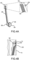
- FIGS. 4A and 4B in accordance with various embodiments, views of a gear rack, such as gear rack 302 of FIGS. 3A and 3B , is illustrated.
- screw 204 has been inserted into a first end of the gear rack 302 up to a predefined length, with a portion of the screw 204 left extending from the gear rack to provide for the space of the floating plate and for the screw 204 to translate in a direction defined by the pocket in the IML.
- a second end of the gear rack 302 is coupled to a tensioning mechanism 304.
- Tensioning mechanism 304 may include a knob 306 which includes a gear 308.
- threads on gear 308 of the tensioning mechanism 304 mesh with the threads 406 on the gear rack 302.
- the knob 306 may be turned (by hand or electronically controlled), whereby rotary motion of the gear 308 is translated into linear motion of the gear rack 302, to move the floating plate 202 in a first direction or in a second direction to tension or un-tension the preform.
- FIG. 4B a cross section along the length of a pocket of the pockets 112 in a side section of the side sections 106 is illustrated.
- screws 204 are fed through the floating plate 202 and through a pocket of the pockets 112 such that the threads on an outer portion of the screws 204 engage with threads on an inner portion of openings on the first end of the gear rack 302.
- the threads on an outer portion of the screws 204 engage with threads on an inner portion of openings on the first end of the gear rack 302.
- the gear rack 302 includes threads 406 along one outer surface from the first end of the gear rack 302 to a second end of the gear rack 302.
- the threads 406 mesh with threads on an outer surface of a gear of the tensioning mechanism 304.
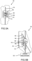
- the screw-based tensioning mechanism 500 includes grip plate guide rails 502, a lead screw 504, a collar assembly 506, a lead nut 508 in the collar assembly 506, and a bracket 510, which are positioned on an inside surface 512 of the IML, such as IML 100 of FIG. 1 .
- the grip plate guide rails 502 provide a guide in instances where the pocket 112 of FIG. 1 may be wider than the screw, such as screw 204 of FIG. 2 . In that regard, the grip plate guide rails 502 align the floating plates, floating plate 202 of FIG. 2 , with the respective pocket 112.
- the floating plate 202 may be coupled to an interface in the collar assembly 506.
- the screw 204 may be fed through the floating plate 202 and through a pocket of the pockets 112 such that the threads on an outer portion of the screw 204 engage with threads on an inner portion of an opening within the collar assembly 506.
- the threads on the outer surface of the lead screw 504 interfaces with threads on an inner surface of the lead nut 508 in the collar assembly 506.
- interaction between the lead screw 504 and the lead nut 508 causes the lead nut to transition in a translation direction.
- the collar assembly 506 is configured to be fixed within the bracket 510.
- bracket 510 reinforces the connection between the collar assembly 506 and the floating plate 202.
- bracket 510 may be fixed to the floating plate 202 to further reinforce the translating movement between the lead nut 508 and/or collar assembly 506 and the floating plate 202.
- the lead screw 504 is fixed at both ends such that the lead screw 504 rotates when acted upon by a crank mechanism 516, such as hand crank, mechanical crank, or electrical crank, among others, that has a gearing mechanism with teeth that interfaces with the threads of the lead screw 504.
- FIG. 6 a cross section of the screw-based tensioning system, such as screw-based tensioning mechanism 500 of FIGS. 5A and 5B , is illustrated.
- the floating plate 202 of FIG. 2 is coupled to an interface in the collar assembly 506.
- a screw such as screw 204 of FIG. 2
- the lead screw 504 interfaces with the lead nut 508 in the collar assembly 506.
- interaction between the lead screw 504 and the lead nut 508 causes the lead nut to transition in a translation direction 602.
- the collar assembly 506 is configured to be fixed within the bracket 510.
- extensions 514 on the bracket 510 glide along the inside surface 512 of the IML.
- bracket 510 reinforces the connection between the collar assembly 506 and the floating plate 202.
- the bracket 510 may be fixed to the floating plate 202 to further reinforce the translating movement between the lead nut 508 and/or collar assembly 506 and the floating plate 202.
- FIGS. 7A and 7B a grip strip application process is illustrated.
- an adhesion material 702 is applied to an outer surface of the floating plates 202, as illustrated in FIG. 7A .
- the adhesion material 702 may be double-sided adhesive tape or glue, among others.
- grip strips 704 are applied to the adhesion material 702.
- the adhesion material 702 bonds the grip strips 704 to the floating plates 202.
- the grip strips 704 may be bonded to the floating plates 202 through mechanical methods, such as by using screws.
- the grip strips 704 provide gripping mechanisms to grip the preform, such as pins angled downward, sharp teeth, or hooks, among others.
- the gripping mechanism provide for pulling the preform as tension is applied via the described tensioning mechanisms.
- a translation direction 602a is not the same as a second translation direction 602b.
- translation direction 602a and translation direction 602b are linear.
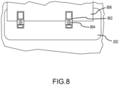
- bladder-activated clamps 802 may be attached to the floating plate 202.
- the bladder-activated clamps 802 may be coupled to the floating plate via screws 804.
- the bladder-activated clamps 802 may be coupled to one of the above-described tensioning mechanisms, such as by replacing screws 204 of FIG. 2 with a longer screw fed through the floating plate 202 and through a pocket of the pockets 112 of FIG. 2 such that the threads on an outer portion of the screws 204 engage, for example, with threads on an inner portion of openings on the first end of the gear rack 302 of FIG.
- bladder-activated clamps 802 clamps onto the preform board 806.
- bladder-activated clamps 802 may be used in conjunction with grip strips 704 of FIGS. 7A and 7B . In that regard, the bladder-activated clamps 802 provide a clamping force to hold the preform board 806 to the grip strips 704 (or floating plate 202 if grip strips 704 are omitted).
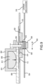
- FIG. 9 a cross section of the screw-based tensioning system, such as screw-based tensioning mechanism 500 of FIGS. 5A and 5B , utilizing bladder-activated clamps 802 is illustrated.
- bladder-activated clamp 802 is coupled to the collar assembly 506 via the floating plate 202 of FIG. 2 .
- screw 804 is fed through an opening in the bladder-activated clamps 802, through an opening in the floating plate 202, and through a pocket of the pockets 112 such that the threads on an outer portion of the screw 804 engage with threads on an inner portion of an opening within the collar assembly 506.
- the lead screw 504 interfaces with the lead nut 508 in the collar assembly 506.
- interaction between the lead screw 504 and the lead nut 508 causes the lead nut 508 to transition in a translation direction 602.
- the collar assembly 506 is configured to be fixed within the bracket 510.
- extensions 514 on the bracket 510 glide along the inside surface 512 of the IML.
- bracket 510 reinforces the connection between the collar assembly 506 and the floating plate 202.
- the bracket 510 may be fixed to the floating plate 202 to further reinforce the translating movement between the lead nut 508 and/or collar assembly 506 and the floating plate 202.
- bladder-activated clamp 802 defines a recess or pocket 808 facing the preform board 806.
- bladder-activated clamp 802 may comprise a bladder support body 810 defining the pocket.
- an opening of the pocket 808 may be enclosed by the preform board 806.
- a bladder 812 (also referred to herein as clamping bladder) is disposed in pocket 808 of the bladder support body 810.
- Bladder 812 may be made from an elastomeric material such as rubber, among other materials.
- Bladder 812 may be mechanically, electrically, and/or pneumatically actuated (e.g., inflated) to provide a clamping force to hold the preform board 806, such as a peripheral portion of the preform board 806, to the floating plate 202. Stated differently, bladder 812 may be configured to expand to clamp preform board 806 between the bladder 812 and a clamping surface (e.g., the floating plate 202). Bladder 812 may be controlled using displacement, load, or visual sensors with feedback loops tied to the floating plate 202. Although illustrated together with a screw-based tensioning system in FIG. 9 , it should be understood that bladder-activated clamp 802 may be used together with other types of tensioning systems, such as tensioning mechanism 304 of FIG. 3 for example.
- FIG. 10 in accordance with various embodiments, tensioning of a preform over an inner-mold line utilizing tensioning systems is illustrated.
- the preform board 806 of FIG. 8 is laid over the top section 102 of the IML 100 of FIG. 1 .
- the preform board 806 is then folded over the top section 102, pressing the preform grip area 1102 at the end of the preform board 806 in contact with the grip strips 704 on the floating plates 202 of FIG. 7B .
- a tensioning system controls 1104 such as tensioning mechanism 304 of FIG. 3 or crank mechanism 516 of FIG.
- a plurality of clamps such as bladder-activated clamps 802 of FIG. 9 , may provide a clamping force to hold the preform board 806 in contact with the grip strips 704.
- a plurality of bladder areas 1110 are highlighted with dashed lines.
- the bladder areas 1110 may be disposed throughout the preform board 806 at various locations depending on the geometry and contours of IML surface 110 and/or the desired granularity of compression control. It should be understood that the bladder areas 1110 outlined in FIG. 11A are exemplary and the location of, and spacing between, bladder areas may be varied (e.g., there may be little to no spacing between bladders). In various embodiments, the bladder areas 1110 do not encompass the tensioning system controls 1104 of FIG. 10 so that the tensioning system controls 1104 may be easily accessed.
- FIG. 11B a transverse cross-section view of the plurality of bladders 1120 (e.g., bladder 1120a, bladder 1120b, bladder 1120c, bladder 1120d, and bladder 1120d) compressing the preform board 806 between the bladders 1120 and the IML surface 110 is illustrated.
- the bladders 1120 may be discretely dispersed along the preform board 806 in the transverse direction (e.g., along the X-direction).
- the bladders 1120 may be mounted to a caul plate 1130 (e.g., a metal plate, a composite plate, a plastic plate, or the like) which is moveable with respect to the IML tool 100.
- the caul plate 1130 has a different rigidity from that of the bladders 1120.
- the caul plate 1130 is more rigid than the bladders 1120, in accordance with various embodiments.
- FIG. 11C a longitudinal cross-section view, taken perpendicular to the transverse cross-section view of FIG. 11B , of the plurality of bladders 1120 (e.g., bladder 1120f, bladder 1120c, and bladder 1120g) compressing the preform board 806 between the bladders 1120 and the IML surface 110 is illustrated.
- the bladders 1120 may be discretely dispersed along the preform board 806 in the longitudinal direction (e.g., along the Z-direction).
- Each bladder 1120 may be strategically located to apply a compressive force to the preform board 806 to compress and shape the preform board 806 to conform to the shape of the IML surface 110.
- the bladders 1120 may vary in size and shape, for example depending on the location of the bladder.
- bladder 1120c may be large than bladder 1120a.
- the shape of bladder 1120b may be different from that of bladder 1120a.
- plurality of bladders 1120 may be controlled (e.g., via a controller/processor) to compress/tension the preform simultaneously. Stated differently, activation (e.g., inflation) of the bladders 1120 may be controlled in concert with the tensioning system, such as screw-based tensioning mechanism 500 of FIGS. 5A and 5B , or gear rack 302 of FIGS. 3A and 3B . In various embodiments, the bladders 1120 may be tied to the translation of the floating grip plates 202/bladder-activated clamps 802. For example, a feedback loop that interfaces with the movement of the floating grip plates 202 may actuate the bladders 1120.
- bladders 1220 e.g., bladders 1220a, 1220b, 1220c, 1220d, 1220e, 1220f, 1220g, 1220h; also referred to herein collectively or individually as a compressing bladder
- bladders 1220 may be similar to bladders 1120 of FIG. 11B and FIG. 11C .
- Bladders 1220 may receive fluid from a fluid source 1222.
- the fluid source 1222 may comprise a valve 1224 for regulating the flow of fluid to the bladders 1220.
- a control unit 1205 may be in electronic communication with valve 1224 for controlling the state of valve 1224.
- valve 1224 comprises a plurality of valves for individually controlling each bladder 1220. Activating bladders one at a time tends to allow preform tension/compression to be more precisely applied dependent on desired geometry of the preform.
- Control unit 1205 may further be in electronic communication with a tensioning system 1216.
- Tensioning system 1216 may be similar to screw-based tensioning mechanism 500 of FIGS. 5A and 5B , or gear rack 302 of FIGS. 3A and 3B . In this manner, control unit 1205 may control tension on a preform board, such as preform board 806 (see FIG. 11 ).
- Control unit 1205 may further be in electronic communication with a valve 1234 for a fluid source 1232. Although illustrated as having two fluid sources 1222 and 1232, it should be understood that a common fluid source may be utilized for the forming system of the present disclosure.
- a bladder 1212 may receive fluid from fluid source 1232.
- the fluid may be a compressible fluid (e.g., a gas such as air) or an incompressible fluid (e.g., water or a hydraulic fluid).
- Bladder 1212 may be similar to bladder 812 of FIG. 9 .
- bladder 1212 may be configured to apply a clamping force to a preform board for the tensioning system 1216. In this manner, control unit 1205 may control a clamping force on a preform board, such as preform board 806 (see FIG. 11 ).
- control unit 1205 may be configured to control activation of bladders 1220 (via valve 1224) in concert with tensioning system 1216 and/or bladder 1212 (via valve 1234).
- control unit 1205 may operate bladders 1220 and tensioning system 1216 simultaneously or in sequence to allow the preform to be stretched as it is being compressed.
- bladder 1220 and tensioning system 1216 pairs may be programmed to operate in sequence to prevent wrinkling, for example working from one end to another end of the preform, or from a section with low linear length to a section of high linear length across a width of the preform, or from a center of the preform outward, among other sequences.
- a first compressing bladder 1220 and a first clamping bladder 1212 may be activated at a first time to apply a first compressive force and a first tension force, respectively, to the preform
- a second compressing bladder 1220 and a second clamping bladder 1212 may be activated at a second time to apply a second compressive force and a second tension force, respectively, to the preform.
- bladders 1220 may be activated based upon feedback from tensioning system 1216 (e.g., as a function of the position of the tensioning system 1216 or a measured force being applied onto the preform by the tensioning system 1216).
- a first compressive force applied by one or more bladders 1220 may be increased (e.g., by increasing an inflation pressure of the bladder 1220) while simultaneously increasing a first tension force applied by the tensioning system (e.g., by translating a floating plate, such as floating plate 202 of FIG. 7B .
- the first compressive force applied by one or more bladders 1220 may be increased (e.g., by increasing an inflation pressure of the bladder 1220) coupled with increasing the first tension force applied by the tensioning system (e.g., by translating a floating plate, such as floating plate 202 of FIG. 7B .
- a manufacturing method for forming a preform into a shaped body is illustrated.
- the method 1300 is described with reference to FIGS. 1 thru 12 .
- a preform board such as preform board 806 of FIG. 8
- the preform board is laid onto a top section of the IML, such as IML 100 of FIG. 1 .
- the preform board is folded over the sides of the IML.
- a preform grip area such as preform grip area 1102 of FIG. 10
- a bladder such as bladder 812 of FIG.
- a clamping force is applied to the preform.
- tension is applied to the preform by activating one or more of the tensioning system controls, such as the tensioning system controls 1104 of FIG. 10 , to translate the floating plates.
- a bladder such as one or more of bladders 1120 of FIG. 11B and FIG. 11C , is activated to apply a compressive force to the preform thereby reducing or eliminating undesired wrinkling and kinking in the preform during part forming and forming the shaped body.
- references to "one embodiment,” “an embodiment,” “various embodiments,” etc. indicate that the embodiment described may include a particular feature, structure, or characteristic, but every embodiment may not necessarily include the particular feature, structure, or characteristic. Moreover, such phrases are not necessarily referring to the same embodiment. Further, when a particular feature, structure, or characteristic is described in connection with an embodiment, it is submitted that it is within the knowledge of one skilled in the art to affect such feature, structure, or characteristic in connection with other embodiments whether or not explicitly described. After reading the description, it will be apparent to one skilled in the relevant art(s) how to implement the disclosure in alternative embodiments.
- Numbers, percentages, or other values stated herein are intended to include that value, and also other values that are about or approximately equal to the stated value, as would be appreciated by one of ordinary skill in the art encompassed by various embodiments of the present disclosure.
- a stated value should therefore be interpreted broadly enough to encompass values that are at least close enough to the stated value to perform a desired function or achieve a desired result.
- the stated values include at least the variation to be expected in a suitable industrial process, and may include values that are within 10%, within 5%, within 1%, within 0.1%, or within 0.01% of a stated value.
- the terms “substantially,” “about,” or “approximately” as used herein represent an amount close to the stated amount that still performs a desired function or achieves a desired result.
- the term “substantially,” “about,” or “approximately” may refer to an amount that is within 10% of, within 5% of, within 1% of, within 0.1% of, and within 0.01% of a stated amount or value
Landscapes
- Engineering & Computer Science (AREA)
- Mechanical Engineering (AREA)
- Chemical & Material Sciences (AREA)
- Composite Materials (AREA)
- Moulds For Moulding Plastics Or The Like (AREA)
- Physics & Mathematics (AREA)
- Fluid Mechanics (AREA)
Abstract
Description
- The present disclosure relates generally to forming a preform into a shaped body.
- Shaped composite bodies are utilized in aerospace applications. Various systems and methods are known in the art for forming a preform into a shaped body.
- According to a first aspect of the invention, a manufacturing method is provided. The manufacturing method includes arranging a preform over a surface of an inner mold line, folding the preform over sides of the inner mold line, positioning an end of the preform over a floating plate coupled to a side of the inner mold line, clamping the end of the preform to the floating plate, wherein the clamping is provided by activating a clamping bladder to apply a first clamping force to the preform to secure the end of the preform with respect to the floating plate, translating the floating plate in a first direction to apply a first tension on the preform into a shaped body, and activating a first compressing bladder to apply a first compressive force to the preform.
- In various embodiments, the floating plate is coupled to a tensioning system through the side of the inner mold line.
- In various embodiments, the tensioning system is at least one of a gear rack-based tensioning system or a screw-based tensioning system.
- In various embodiments, the floating plate is coupled to the tensioning system through one or more pockets in the side of the inner mold line.
- In various embodiments, the first compressing bladder is activated by inflating the first compressing bladder with a fluid.
- In various embodiments, the first compressing bladder is mounted to a caul plate moveable with respect to the inner mold line. The caul plate may have a different rigidity than the bladder (i.e., the caul plate may be more rigid than the bladder)
- In various embodiments, the manufacturing method further comprises activating a second compressing bladder to apply a second compressive force to the preform, wherein the second compressing bladder is activated after the first compressing bladder.
- In various embodiments, the manufacturing method further comprises increasing the first compressive force coupled with increasing the first tension.
- In various embodiments, the manufacturing method further comprises activating a second compressing bladder to apply a second compressive force to the preform, and activating a third compressing bladder to apply a third compressive force to the preform. The first compressing bladder, the second compressing bladder, and the third compressing bladder may be activated sequentially along a second direction (e.g., from one end of the preform to another). The first compressing bladder, the second compressing bladder, and the third compressing bladder may be activated starting from a center of the preform and working outward toward a periphery of the preform (e.g., from a central location of the preform outward).
- According to another aspect of the invention a system for forming a preform into a shaped body is provided. The system includes an inner mold line, a caul plate, a plurality of compressing bladders mounted to the caul plate, and a floating plate coupled to a side of the inner mold line. The floating plate is configured to receive an end of the preform and translate in a first direction to tension the preform into the shaped body.
- In various embodiments, the system further comprises a grip strip coupled to the floating plate and wherein the grip strip is configured to receive the end of the preform.
- In various embodiments, the system further comprises a tensioning system, wherein the floating plate is coupled to the tensioning system through a side of the inner mold line.
- In various embodiments, the tensioning system is at least one of a gear rack-based tensioning system or a screw-based tensioning system.
- In various embodiments, the system further comprises a fluid source fluidly coupled, via a first valve, to at least one compressing bladder of the plurality of compressing bladders.
- In various embodiments, the system further comprises a clamp comprising a clamping bladder, wherein the clamping bladder is configured to apply a clamping force to the preform to secure the end of the preform with respect to the floating plate.
- According to yet another aspect of the invention a bladder-activated clamp is provided. The bladder-activated clamp includes a clamp body defining a pocket, and a bladder disposed in the pocket of the clamp body. The bladder is configured to expand to apply a clamping force to clamp an item between the bladder and a clamping surface.
- In various embodiments, the bladder-activated clamp further comprises a fluid source, and a valve whereby the fluid source is in fluid communication with the bladder.
- In various embodiments, the bladder-activated clamp further comprises an aperture disposed in the clamp body, and a fastener configured to extend through the aperture for securing the clamp body with respect to the clamping surface.
- In various embodiments, an opening of the pocket is configured to face the clamping surface.
- In various embodiments, the bladder comprises an elastomeric material.
- The present disclosure may include any one or more of the individual features disclosed above and/or below alone or in any combination thereof.
- The foregoing features and elements may be combined in various combinations without exclusivity, unless expressly indicated herein otherwise. These features and elements as well as the operation of the disclosed embodiments will become more apparent in light of the following description and accompanying drawings.
-
-
FIG. 1 illustrates an inner-mold line for use in forming a shaped body from a preform, in accordance with various embodiments. -
FIG. 2 illustrates a coupling of a plurality of floating plates to the IML, in accordance with various embodiments. -
FIGS. 3A and 3B illustrates an isometric view of a gear rack-based tensioning system, in accordance with various embodiments. -
FIGS. 4A and 4B illustrates views of a gear rack, in accordance with various embodiments. -
FIGS. 5A and 5B illustrates a screw-based tensioning system, in accordance with various embodiments. -
FIG. 6 illustrates a cross section of the screw-based tensioning system, in accordance with various embodiments. -
FIGS. 7A and7B illustrates a grip strip application process, in accordance with various embodiments. -
FIG. 8 illustrates a clamping mechanism, in accordance with various embodiments. -
FIG. 9 illustrates a cross section of a bladder-activated clamp installed with a screw-based tensioning system, in accordance with various embodiments. -
FIG. 10 illustrates tensioning of a preform over an inner-mold line utilizing tensioning systems, in accordance with various embodiments. -
FIG. 11A illustrates a plurality of bladder areas with the bladders omitted for ease of illustration, in accordance with various embodiments. -
FIG. 11B illustrates a section view of a plurality of compressing bladders mounted to a caul plate for compressing a preform, in accordance with various embodiments. -
FIG. 11C illustrates a section view, taken perpendicular to the section view ofFIG. 11B , of the plurality of compressing bladders mounted to the caul plate, in accordance with various embodiments. -
FIG. 12 illustrates a schematic view of a control system for the shape forming system, in accordance with various embodiments. -
FIG. 13 illustrates a manufacturing method for forming a preform into a shaped body, in accordance with various embodiments. - The following detailed description of various embodiments herein makes reference to the accompanying drawings, which show various embodiments by way of illustration. While these various embodiments are described in sufficient detail to enable those skilled in the art to practice the disclosure, it should be understood that other embodiments may be realized and that changes may be made without departing from the scope of the disclosure. Thus, the detailed description herein is presented for purposes of illustration only and not of limitation. Furthermore, any reference to singular includes plural embodiments, and any reference to more than one component or step may include a singular embodiment or step. Also, any reference to attached, fixed, connected, or the like may include permanent, removable, temporary, partial, full or any other possible attachment option. Additionally, any reference to without contact (or similar phrases) may also include reduced contact or minimal contact. It should also be understood that unless specifically stated otherwise, references to "a," "an," or "the" may include one or more than one and that reference to an item in the singular may also include the item in the plural. Further, all ranges may include upper and lower values and all ranges and ratio limits disclosed herein may be combined.
- Disclosed herein are systems and methods for forming a preform into a shaped body. The systems and methods relate to complex geometry carbon preforms for C-C composites with curvatures along multiple planes. To properly form a shaped body, appropriate tension must be applied to the preform, such that the preform may be stretched around various corners and radii with little to no wrinkling or fiber kinking - important to achieve target mechanical properties and reproducibility. In various embodiments, the systems and methods disclosed herein, in various embodiments, apply even tension to the side wall edges of the preform. In various embodiments, the preform is coupled to floating grip plates, which are coupled to a male inner mold line (IML) tool. In various embodiments, the floating grip plates impart controlled translation along the IML surface to regulate the tension or stretch on the side walls edges of a preform. In various embodiments, the floating grip plates include an adjustable tensioning system that sits underneath a surface of the IML. In various embodiments, the adjustable tensioning system is controlled by a knob/crank located outside of the tool. In various embodiments, grip strips may be bonded on top of the floating grip plates via adhesive tape or may be mechanically fastened to the grip plate. In various embodiments, the preform is pressed onto the grip strip and may be held onto the grip strips with bladder-activated clamps or hooks, among others. In various embodiments, the preforms may then be compressed by controllable bladder pressure (i.e., positive pressure). In various embodiments, the positive pressure on the preforms may be applied using one or more caul plates and a plurality of pressurized bladders to apply uniform (or varied as desired) pressure and compaction.
- The disclosed systems and methods for forming a preform into a shaped body is an improvement over the current matched-die tooling for shape-forming, in various embodiments, by reducing or eliminating undesired wrinkling and kinking during part forming. The disclosed improvements to tooling and forming, in various embodiments, addresses the wrinkling and uneven compression issues seen in the match-die tooling approach. The utilization of controllable bladders-together with floating grip plates-provides an efficient, yet elegant, way to ensure even compression and/or tension throughout the part, while utilizing best practices from current stretch/shape-forming procedures. In addition, the utilization of a plurality of controllable bladders-together with floating grip plates-provides an elegant mechanism for varying and precisely controlling the compression and/or tension of the preform in different regions thereby allowing the preform to be formed into the desired shape while reducing or eliminating undesired wrinkling or kinking.
- Referring now to
FIG. 1 , in accordance with various embodiments, an inner-mold line for use in forming a shaped body from a preform is illustrated. Inner-mold line (IML) 100 includes atop section 102, abottom section 104,side sections 106, and a plurality ofIML stiffeners 108. In various embodiments, the outer portion of thetop section 102, thebottom section 104, and theside sections 106 form anIML surface 110 for a given preform with given dimensions. In various embodiments, theside sections 106 may be substantially vertical. In various embodiments, theside sections 106 may be substantially parallel to the y-axis. In various embodiments, theside sections 106 may be substantially perpendicular to the x-axis. In various embodiments, theside sections 106 include a plurality of slots orpockets 112 for one or more floating plates. In various embodiments, each of the plurality ofpockets 112 are rectangular shaped slots that provide a clearance for a threaded connection, i.e., a screw and threaded standoff, between a floating plate on an outer portion of theIML 100 and an associated gear rack on an inner portion of theIML 100. In various embodiments, theside sections 106 further include a plurality of thru-holes 114 that provide access to a tensioning system from the outer portion of theIML 100 outside a compression mechanism area. - Turning to
FIG. 2 , in accordance with various embodiments, a coupling of a plurality of floating plates to the IML is illustrated. In various embodiments, a plurality of floatingplates 202 outside theIML 100 ofFIG. 1 may be coupled to a plurality of tensioning mechanisms inside theIML 100. In various embodiments, each floating plate in the plurality of floatingplates 202 may traverse two of the plurality ofpockets 112. In various embodiments, each floating plate in the plurality of floatingplates 202 may be coupled to a respective tensioning mechanism via openings in each floating plate such that each floating plate is coupled using a set ofscrews 204, i.e., four screws, two screws per tensioning mechanism. While in the illustrated example, the floating plate is coupled using four screws, two for each tensioning mechanism, the various embodiments are not limited to the illustrated example. That is, in various embodiments, more or less screws may be utilized. For example, in various embodiments each floating plate in the plurality of floatingplates 202 may be coupled to a respective tensioning mechanism via openings in each floating plate such that each floating plate is coupled using a set of screws, i.e., two screws, one screw per tensioning mechanism. As another example, in various embodiments, each floating plate in the plurality of floatingplates 202 may be coupled to a respective tensioning mechanism via openings in each floating plate such that each floating plate is coupled using a set of screws, i.e., six screws, three screws per tensioning mechanism. In various embodiments, the set of screws may be flat head screws with a tapered angle to the threads. In various embodiments, eachscrew 204 may have an O-ring slid over the threads and up to the head of thescrew 204 along the tapered angle so that the O-ring engages with a respective opening in each floating plate providing an air-tight attachment. - Turning to
FIGS. 3A and 3B , in accordance with various embodiments, an isometric view of a gear rack-based tensioning system is illustrated. In the various embodiments, floatingplate 202 is coupled to a first end ofgear rack 302. In various embodiments, screws 204 are fed through the floatingplate 202 and through a pocket of thepockets 112 such that the threads on an outer portion of thescrews 204 engage with threads on an inner portion of openings on the first end of thegear rack 302. In various embodiments, the floatingplate 202 is secured to thegear rack 302 such that the floatingplate 202 is free to move in a translation direction along theIML surface 110 of theside sections 106 of theIML 100. In that regard, thepockets 112 allow enough clearance for the floatingplates 202 to slide in a first direction or slide in a second direction to tension and un-tension the preform. In various embodiments, a second end of thegear rack 302 is coupled to atensioning mechanism 304, which is hereafter described in detail. - Turning to
FIGS. 4A and 4B , in accordance with various embodiments, views of a gear rack, such asgear rack 302 ofFIGS. 3A and 3B , is illustrated. In the various embodiments, ofFIG. 4A , screw 204 has been inserted into a first end of thegear rack 302 up to a predefined length, with a portion of thescrew 204 left extending from the gear rack to provide for the space of the floating plate and for thescrew 204 to translate in a direction defined by the pocket in the IML. In various embodiments, a second end of thegear rack 302 is coupled to atensioning mechanism 304.Tensioning mechanism 304 may include aknob 306 which includes agear 308. In the various embodiments, threads ongear 308 of thetensioning mechanism 304 mesh with thethreads 406 on thegear rack 302. In various embodiments, theknob 306 may be turned (by hand or electronically controlled), whereby rotary motion of thegear 308 is translated into linear motion of thegear rack 302, to move the floatingplate 202 in a first direction or in a second direction to tension or un-tension the preform. - In the various embodiments of
FIG. 4B , a cross section along the length of a pocket of thepockets 112 in a side section of theside sections 106 is illustrated. In various embodiments, screws 204 are fed through the floatingplate 202 and through a pocket of thepockets 112 such that the threads on an outer portion of thescrews 204 engage with threads on an inner portion of openings on the first end of thegear rack 302. In various embodiments, the threads on an outer portion of thescrews 204 engage with threads on an inner portion of openings on the first end of thegear rack 302. In various embodiments, thegear rack 302 includesthreads 406 along one outer surface from the first end of thegear rack 302 to a second end of thegear rack 302. In various embodiments, thethreads 406 mesh with threads on an outer surface of a gear of thetensioning mechanism 304. - Turning to
FIGS. 5A and 5B , in accordance with various embodiments, a screw-based tensioning system is illustrated. In various embodiments, the screw-basedtensioning mechanism 500 includes gripplate guide rails 502, alead screw 504, acollar assembly 506, alead nut 508 in thecollar assembly 506, and abracket 510, which are positioned on aninside surface 512 of the IML, such asIML 100 ofFIG. 1 . In various embodiments, the gripplate guide rails 502 provide a guide in instances where thepocket 112 ofFIG. 1 may be wider than the screw, such asscrew 204 ofFIG. 2 . In that regard, the gripplate guide rails 502 align the floating plates, floatingplate 202 ofFIG. 2 , with therespective pocket 112. In the various embodiments, the floatingplate 202 may be coupled to an interface in thecollar assembly 506. In that regard, thescrew 204 may be fed through the floatingplate 202 and through a pocket of thepockets 112 such that the threads on an outer portion of thescrew 204 engage with threads on an inner portion of an opening within thecollar assembly 506. In various embodiments, the threads on the outer surface of thelead screw 504 interfaces with threads on an inner surface of thelead nut 508 in thecollar assembly 506. In various embodiments, interaction between thelead screw 504 and thelead nut 508 causes the lead nut to transition in a translation direction. In various embodiments, thecollar assembly 506 is configured to be fixed within thebracket 510. In various embodiments,extensions 514 on thebracket 510 glide along theinside surface 512 of the IML. In that regard,bracket 510 reinforces the connection between thecollar assembly 506 and the floatingplate 202. In various embodiments, thebracket 510 may be fixed to the floatingplate 202 to further reinforce the translating movement between thelead nut 508 and/orcollar assembly 506 and the floatingplate 202. In various embodiments, thelead screw 504 is fixed at both ends such that thelead screw 504 rotates when acted upon by acrank mechanism 516, such as hand crank, mechanical crank, or electrical crank, among others, that has a gearing mechanism with teeth that interfaces with the threads of thelead screw 504. - Turning to
FIG. 6 , in accordance with various embodiments, a cross section of the screw-based tensioning system, such as screw-basedtensioning mechanism 500 ofFIGS. 5A and 5B , is illustrated. In various embodiments, the floatingplate 202 ofFIG. 2 is coupled to an interface in thecollar assembly 506. In that regard, a screw, such asscrew 204 ofFIG. 2 , is fed through the floatingplate 202 and through a pocket of thepockets 112 such that the threads on an outer portion of thescrew 204 engage with threads on an inner portion of an opening within thecollar assembly 506. In various embodiments, thelead screw 504 interfaces with thelead nut 508 in thecollar assembly 506. In various embodiments, interaction between thelead screw 504 and thelead nut 508 causes the lead nut to transition in atranslation direction 602. In various embodiments, thecollar assembly 506 is configured to be fixed within thebracket 510. In various embodiments,extensions 514 on thebracket 510 glide along theinside surface 512 of the IML. In that regard,bracket 510 reinforces the connection between thecollar assembly 506 and the floatingplate 202. In various embodiments, thebracket 510 may be fixed to the floatingplate 202 to further reinforce the translating movement between thelead nut 508 and/orcollar assembly 506 and the floatingplate 202. - Turning to
FIGS. 7A and7B , in accordance with various embodiments, a grip strip application process is illustrated. In various embodiments, once the floatingplates 202 are coupled to theIML surface 110 of theIML 100, anadhesion material 702 is applied to an outer surface of the floatingplates 202, as illustrated inFIG. 7A . In various embodiments, theadhesion material 702 may be double-sided adhesive tape or glue, among others. In various embodiments, as illustrated inFIG. 7B , once theadhesion material 702 is applied, grip strips 704 are applied to theadhesion material 702. In various embodiments, theadhesion material 702 bonds the grip strips 704 to the floatingplates 202. In various embodiments, rather than using theadhesion material 702, the grip strips 704 may be bonded to the floatingplates 202 through mechanical methods, such as by using screws. In various embodiments, the grip strips 704 provide gripping mechanisms to grip the preform, such as pins angled downward, sharp teeth, or hooks, among others. In various embodiments, the gripping mechanism provide for pulling the preform as tension is applied via the described tensioning mechanisms. In various embodiments, atranslation direction 602a is not the same as asecond translation direction 602b. In various embodiments,translation direction 602a andtranslation direction 602b are linear. - Turing now to
FIG. 8 , in accordance with various embodiments, a clamping mechanism is illustrated. In various embodiments, bladder-activatedclamps 802 may be attached to the floatingplate 202. In various embodiments, the bladder-activatedclamps 802 may be coupled to the floating plate via screws 804. In various embodiments, the bladder-activatedclamps 802 may be coupled to one of the above-described tensioning mechanisms, such as by replacingscrews 204 ofFIG. 2 with a longer screw fed through the floatingplate 202 and through a pocket of thepockets 112 ofFIG. 2 such that the threads on an outer portion of thescrews 204 engage, for example, with threads on an inner portion of openings on the first end of thegear rack 302 ofFIG. 3A and 3B or with threads on an inner portion of an opening within thecollar assembly 506 ofFIG. 5A and 5B . In various embodiments, bladder-activatedclamps 802 clamps onto thepreform board 806. In various embodiments, bladder-activatedclamps 802 may be used in conjunction with grip strips 704 ofFIGS. 7A and7B . In that regard, the bladder-activatedclamps 802 provide a clamping force to hold thepreform board 806 to the grip strips 704 (or floatingplate 202 if grip strips 704 are omitted). - Turning to
FIG. 9 , in accordance with various embodiments, a cross section of the screw-based tensioning system, such as screw-basedtensioning mechanism 500 ofFIGS. 5A and 5B , utilizing bladder-activatedclamps 802 is illustrated. In various embodiments, bladder-activatedclamp 802 is coupled to thecollar assembly 506 via the floatingplate 202 ofFIG. 2 . In that regard,screw 804 is fed through an opening in the bladder-activatedclamps 802, through an opening in the floatingplate 202, and through a pocket of thepockets 112 such that the threads on an outer portion of thescrew 804 engage with threads on an inner portion of an opening within thecollar assembly 506. In various embodiments, thelead screw 504 interfaces with thelead nut 508 in thecollar assembly 506. In various embodiments, interaction between thelead screw 504 and thelead nut 508 causes thelead nut 508 to transition in atranslation direction 602. In various embodiments, thecollar assembly 506 is configured to be fixed within thebracket 510. In various embodiments,extensions 514 on thebracket 510 glide along theinside surface 512 of the IML. In that regard,bracket 510 reinforces the connection between thecollar assembly 506 and the floatingplate 202. In various embodiments, thebracket 510 may be fixed to the floatingplate 202 to further reinforce the translating movement between thelead nut 508 and/orcollar assembly 506 and the floatingplate 202. - In various embodiments, bladder-activated
clamp 802 defines a recess orpocket 808 facing thepreform board 806. For example, bladder-activatedclamp 802 may comprise abladder support body 810 defining the pocket. In various embodiments, in the installed position, an opening of thepocket 808 may be enclosed by thepreform board 806. A bladder 812 (also referred to herein as clamping bladder) is disposed inpocket 808 of thebladder support body 810.Bladder 812 may be made from an elastomeric material such as rubber, among other materials.Bladder 812 may be mechanically, electrically, and/or pneumatically actuated (e.g., inflated) to provide a clamping force to hold thepreform board 806, such as a peripheral portion of thepreform board 806, to the floatingplate 202. Stated differently,bladder 812 may be configured to expand to clamppreform board 806 between thebladder 812 and a clamping surface (e.g., the floating plate 202).Bladder 812 may be controlled using displacement, load, or visual sensors with feedback loops tied to the floatingplate 202. Although illustrated together with a screw-based tensioning system inFIG. 9 , it should be understood that bladder-activatedclamp 802 may be used together with other types of tensioning systems, such astensioning mechanism 304 ofFIG. 3 for example. - Turning to
FIG. 10 , in accordance with various embodiments, tensioning of a preform over an inner-mold line utilizing tensioning systems is illustrated. In various embodiments, thepreform board 806 ofFIG. 8 is laid over thetop section 102 of theIML 100 ofFIG. 1 . Thepreform board 806 is then folded over thetop section 102, pressing thepreform grip area 1102 at the end of thepreform board 806 in contact with the grip strips 704 on the floatingplates 202 ofFIG. 7B . Once thepreform grip area 1102 is in contact with the grip strips 704, a tensioning system controls 1104, such astensioning mechanism 304 ofFIG. 3 or crankmechanism 516 ofFIG. 6 , is utilized to tension thepreform board 806 over theIML surface 110 ofFIG. 1 . Moreover, a plurality of clamps, such as bladder-activatedclamps 802 ofFIG. 9 , may provide a clamping force to hold thepreform board 806 in contact with the grip strips 704. - Turning to
FIG. 11A , in accordance with various embodiments, a plurality ofbladder areas 1110 are highlighted with dashed lines. In various embodiments, thebladder areas 1110 may be disposed throughout thepreform board 806 at various locations depending on the geometry and contours ofIML surface 110 and/or the desired granularity of compression control. It should be understood that thebladder areas 1110 outlined inFIG. 11A are exemplary and the location of, and spacing between, bladder areas may be varied (e.g., there may be little to no spacing between bladders). In various embodiments, thebladder areas 1110 do not encompass the tensioning system controls 1104 ofFIG. 10 so that the tensioning system controls 1104 may be easily accessed. - Turning to
FIG. 11B , in accordance with various embodiments, a transverse cross-section view of the plurality of bladders 1120 (e.g.,bladder 1120a,bladder 1120b,bladder 1120c,bladder 1120d, andbladder 1120d) compressing thepreform board 806 between thebladders 1120 and theIML surface 110 is illustrated. Thebladders 1120 may be discretely dispersed along thepreform board 806 in the transverse direction (e.g., along the X-direction). Thebladders 1120 may be mounted to a caul plate 1130 (e.g., a metal plate, a composite plate, a plastic plate, or the like) which is moveable with respect to theIML tool 100. Thecaul plate 1130 has a different rigidity from that of thebladders 1120. Thecaul plate 1130 is more rigid than thebladders 1120, in accordance with various embodiments. - Turning to
FIG. 11C , in accordance with various embodiments, a longitudinal cross-section view, taken perpendicular to the transverse cross-section view ofFIG. 11B , of the plurality of bladders 1120 (e.g.,bladder 1120f,bladder 1120c, andbladder 1120g) compressing thepreform board 806 between thebladders 1120 and theIML surface 110 is illustrated. Thebladders 1120 may be discretely dispersed along thepreform board 806 in the longitudinal direction (e.g., along the Z-direction). Eachbladder 1120 may be strategically located to apply a compressive force to thepreform board 806 to compress and shape thepreform board 806 to conform to the shape of theIML surface 110. Moreover, thebladders 1120 may vary in size and shape, for example depending on the location of the bladder. For example,bladder 1120c may be large thanbladder 1120a. Moreover, the shape ofbladder 1120b may be different from that ofbladder 1120a. - In various embodiments, plurality of
bladders 1120 may be controlled (e.g., via a controller/processor) to compress/tension the preform simultaneously. Stated differently, activation (e.g., inflation) of thebladders 1120 may be controlled in concert with the tensioning system, such as screw-basedtensioning mechanism 500 ofFIGS. 5A and 5B , orgear rack 302 ofFIGS. 3A and 3B . In various embodiments, thebladders 1120 may be tied to the translation of the floatinggrip plates 202/bladder-activatedclamps 802. For example, a feedback loop that interfaces with the movement of the floatinggrip plates 202 may actuate thebladders 1120. - Turning to
FIG. 12 , in accordance with various embodiments, a schematic view of a plurality of bladders 1220 (e.g., bladders 1220a, 1220b, 1220c, 1220d, 1220e, 1220f, 1220g, 1220h; also referred to herein collectively or individually as a compressing bladder) for a system for forming a preform into a shaped body is illustrated. In various embodiments,bladders 1220 may be similar tobladders 1120 ofFIG. 11B and FIG. 11C .Bladders 1220 may receive fluid from afluid source 1222. Thefluid source 1222 may comprise avalve 1224 for regulating the flow of fluid to thebladders 1220. Acontrol unit 1205 may be in electronic communication withvalve 1224 for controlling the state ofvalve 1224. In various embodiments,valve 1224 comprises a plurality of valves for individually controlling eachbladder 1220. Activating bladders one at a time tends to allow preform tension/compression to be more precisely applied dependent on desired geometry of the preform. -
Control unit 1205 may further be in electronic communication with atensioning system 1216.Tensioning system 1216 may be similar to screw-basedtensioning mechanism 500 ofFIGS. 5A and 5B , orgear rack 302 ofFIGS. 3A and 3B . In this manner,control unit 1205 may control tension on a preform board, such as preform board 806 (seeFIG. 11 ). -
Control unit 1205 may further be in electronic communication with avalve 1234 for afluid source 1232. Although illustrated as having twofluid sources bladder 1212 may receive fluid fromfluid source 1232. The fluid may be a compressible fluid (e.g., a gas such as air) or an incompressible fluid (e.g., water or a hydraulic fluid).Bladder 1212 may be similar tobladder 812 ofFIG. 9 . In this regard,bladder 1212 may be configured to apply a clamping force to a preform board for thetensioning system 1216. In this manner,control unit 1205 may control a clamping force on a preform board, such as preform board 806 (seeFIG. 11 ). - In various embodiments,
control unit 1205 may be configured to control activation of bladders 1220 (via valve 1224) in concert withtensioning system 1216 and/or bladder 1212 (via valve 1234). In various embodiments,control unit 1205 may operatebladders 1220 andtensioning system 1216 simultaneously or in sequence to allow the preform to be stretched as it is being compressed. In various embodiments,bladder 1220 andtensioning system 1216 pairs may be programmed to operate in sequence to prevent wrinkling, for example working from one end to another end of the preform, or from a section with low linear length to a section of high linear length across a width of the preform, or from a center of the preform outward, among other sequences. For example, afirst compressing bladder 1220 and afirst clamping bladder 1212 may be activated at a first time to apply a first compressive force and a first tension force, respectively, to the preform, and asecond compressing bladder 1220 and asecond clamping bladder 1212 may be activated at a second time to apply a second compressive force and a second tension force, respectively, to the preform. In various embodiments,bladders 1220 may be activated based upon feedback from tensioning system 1216 (e.g., as a function of the position of thetensioning system 1216 or a measured force being applied onto the preform by the tensioning system 1216). For example, a first compressive force applied by one ormore bladders 1220 may be increased (e.g., by increasing an inflation pressure of the bladder 1220) while simultaneously increasing a first tension force applied by the tensioning system (e.g., by translating a floating plate, such as floatingplate 202 ofFIG. 7B . The first compressive force applied by one ormore bladders 1220 may be increased (e.g., by increasing an inflation pressure of the bladder 1220) coupled with increasing the first tension force applied by the tensioning system (e.g., by translating a floating plate, such as floatingplate 202 ofFIG. 7B . - Referring now to
FIG. 13 , in accordance with various embodiments, a manufacturing method for forming a preform into a shaped body is illustrated. For ease of description, the method 1300 is described with reference toFIGS. 1 thru 12 . Instep 1302, a preform board, such aspreform board 806 ofFIG. 8 , is laid onto a top section of the IML, such asIML 100 ofFIG. 1 . Atblock 1304, the preform board is folded over the sides of the IML. Atblock 1306, a preform grip area, such aspreform grip area 1102 ofFIG. 10 , is pressed into contact with floating plates of the IML, such as floatingplates 202 ofFIG. 7B . Atblock 1308, a bladder, such asbladder 812 ofFIG. 9 , is activated to apply a clamping force to the preform. Atblock 1310, tension is applied to the preform by activating one or more of the tensioning system controls, such as the tensioning system controls 1104 ofFIG. 10 , to translate the floating plates. Atblock 1312, a bladder, such as one or more ofbladders 1120 ofFIG. 11B and FIG. 11C , is activated to apply a compressive force to the preform thereby reducing or eliminating undesired wrinkling and kinking in the preform during part forming and forming the shaped body. - Benefits and other advantages have been described herein with regard to specific embodiments. Furthermore, the connecting lines shown in the various figures contained herein are intended to represent exemplary functional relationships and/or physical couplings between the various elements. It should be noted that many alternative or additional functional relationships or physical connections may be present in a practical system. However, the benefits, advantages, and any elements that may cause any benefit or advantage to occur or become more pronounced are not to be construed as critical, required, or essential features or elements of the disclosure. The scope of the disclosure is accordingly to be limited by nothing other than the appended claims, in which reference to an element in the singular is not intended to mean "one and only one" unless explicitly so stated, but rather "one or more." Moreover, where a phrase similar to "at least one of A, B, or C" is used in the claims, it is intended that the phrase be interpreted to mean that A alone may be present in an embodiment, B alone may be present in an embodiment, C alone may be present in an embodiment, or that any combination of the elements A, B and C may be present in a single embodiment; for example, A and B, A and C, B and C, or A and B and C.
- Systems, methods, and apparatus are provided herein. In the detailed description herein, references to "one embodiment," "an embodiment," "various embodiments," etc., indicate that the embodiment described may include a particular feature, structure, or characteristic, but every embodiment may not necessarily include the particular feature, structure, or characteristic. Moreover, such phrases are not necessarily referring to the same embodiment. Further, when a particular feature, structure, or characteristic is described in connection with an embodiment, it is submitted that it is within the knowledge of one skilled in the art to affect such feature, structure, or characteristic in connection with other embodiments whether or not explicitly described. After reading the description, it will be apparent to one skilled in the relevant art(s) how to implement the disclosure in alternative embodiments.
- Numbers, percentages, or other values stated herein are intended to include that value, and also other values that are about or approximately equal to the stated value, as would be appreciated by one of ordinary skill in the art encompassed by various embodiments of the present disclosure. A stated value should therefore be interpreted broadly enough to encompass values that are at least close enough to the stated value to perform a desired function or achieve a desired result. The stated values include at least the variation to be expected in a suitable industrial process, and may include values that are within 10%, within 5%, within 1%, within 0.1%, or within 0.01% of a stated value. Additionally, the terms "substantially," "about," or "approximately" as used herein represent an amount close to the stated amount that still performs a desired function or achieves a desired result. For example, the term "substantially," "about," or "approximately" may refer to an amount that is within 10% of, within 5% of, within 1% of, within 0.1% of, and within 0.01% of a stated amount or value.
- Furthermore, no element, component, or method step in the present disclosure is intended to be dedicated to the public regardless of whether the element, component, or method step is explicitly recited in the claims. No claim element herein is to be construed under the provisions of 35 U.S.C. 112(f) unless the element is expressly recited using the phrase "means for." As used herein, the terms "comprises," "comprising," or any other variation thereof, are intended to cover a non-exclusive inclusion, such that a process, method, article, or apparatus that comprises a list of elements does not include only those elements but may include other elements not expressly listed or inherent to such process, method, article, or apparatus.
- Finally, it should be understood that any of the above-described concepts can be used alone or in combination with any or all of the other above-described concepts. Although various embodiments have been disclosed and described, one of ordinary skill in this art would recognize that certain modifications would come within the scope of this disclosure. Accordingly, the description is not intended to be exhaustive or to limit the principles described or illustrated herein to any precise form. Many modifications and variations are possible in light of the above teaching.
Claims (15)
- A manufacturing method, comprising:arranging a preform over a surface of an inner mold line;folding the preform over sides of the inner mold line;positioning an end of the preform over a floating plate coupled to a side of the inner mold line;clamping the end of the preform to the floating plate, wherein the clamping is provided by activating a clamping bladder to apply a first clamping force to the preform to secure the end of the preform with respect to the floating plate;translating the floating plate in a first direction to apply a first tension on the preform into a shaped body; andactivating a first compressing bladder to apply a first compressive force to the preform.
- The manufacturing method of claim 1, wherein the floating plate is coupled to a tensioning system through the side of the inner mold line.
- The manufacturing method of claim 2, wherein the tensioning system is at least one of a gear rack-based tensioning system or a screw-based tensioning system.
- The manufacturing method of claim 2 or 3, wherein the floating plate is coupled to the tensioning system through one or more pockets in the side of the inner mold line.
- The manufacturing method of any preceding claim,wherein the first compressing bladder is activated by inflating the first compressing bladder with a fluid; and/orwherein the first compressing bladder is mounted to a caul plate moveable with respect to the inner mold line, and wherein the caul plate has a different rigidity than the first compressing bladder.
- The manufacturing method of any preceding claim, further comprising activating a second compressing bladder to apply a second compressive force to the preform, wherein the second compressing bladder is activated after the first compressing bladder.
- The manufacturing method of any preceding claim, further comprising:
increasing the first compressive force coupled with increasing the first tension. - The manufacturing method of any preceding claim, further comprising:activating a second compressing bladder to apply a second compressive force to the preform; andactivating a third compressing bladder to apply a third compressive force to the preform;wherein at least one of:the first compressing bladder, the second compressing bladder, and the third compressing bladder are activated sequentially along a second direction; orthe first compressing bladder, the second compressing bladder, and the third compressing bladder are activated starting from a center of the preform and working outward toward a periphery of the preform.
- A system for forming a preform into a shaped body, the system comprising:an inner mold line;a caul plate;a plurality of compressing bladders mounted to the caul plate; anda floating plate coupled to a side of the inner mold line and configured to:receive an end of the preform; andtranslate in a first direction to tension the preform into the shaped body.
- The system of claim 9, further comprising:
a grip strip coupled to the floating plate and wherein the grip strip is configured to receive the end of the preform. - The system of claim 9 or 10, further comprising:a tensioning system, wherein the floating plate is coupled to the tensioning system through a side of the inner mold line,wherein, optionally, the tensioning system is at least one of a gear rack-based tensioning system or a screw-based tensioning system.
- The system of any of claims 9 to 11, further comprising a fluid source fluidly coupled, via a first valve, to at least one compressing bladder of the plurality of compressing bladders; and/or
further comprising a clamp comprising a clamping bladder, wherein the clamping bladder is configured to apply a clamping force to the preform to secure the end of the preform with respect to the floating plate. - A bladder-activated clamp, comprising:a clamp body defining a pocket; anda bladder disposed in the pocket of the clamp body;wherein the bladder is configured to expand to apply a clamping force to clamp an item between the bladder and a clamping surface.
- The bladder-activated clamp of claim 13,
further comprising:a fluid source; anda valve whereby the fluid source is in fluid communication with the bladder, and/orfurther comprising:an aperture disposed in the clamp body; anda fastener configured to extend through the aperture for securing the clamp body with respect to the clamping surface. - The bladder-activated clamp of claim 13 or 14,wherein an opening of the pocket is configured to face the clamping surface, and/orwherein the bladder comprises an elastomeric material.
Applications Claiming Priority (1)
| Application Number | Priority Date | Filing Date | Title |
|---|---|---|---|
| US17/978,053 US12508747B2 (en) | 2022-10-31 | 2022-10-31 | Systems and methods for bladder pressure forming a preform into a shaped body |
Publications (1)
| Publication Number | Publication Date |
|---|---|
| EP4360857A1 true EP4360857A1 (en) | 2024-05-01 |
Family
ID=88416877
Family Applications (1)
| Application Number | Title | Priority Date | Filing Date |
|---|---|---|---|
| EP23204208.5A Withdrawn EP4360857A1 (en) | 2022-10-31 | 2023-10-17 | Systems and methods for bladder pressure forming a preform into a shaped body |
Country Status (2)
| Country | Link |
|---|---|
| US (2) | US12508747B2 (en) |
| EP (1) | EP4360857A1 (en) |
Citations (3)
| Publication number | Priority date | Publication date | Assignee | Title |
|---|---|---|---|---|
| US5290167A (en) * | 1990-10-08 | 1994-03-01 | Sumitomo Heavy Industries, Ltd. | Method of manufacturing three-dimensional parts using sheets of thermoplastic resin high-performance fiber-reinforced composite material and apparatus therefor |
| US20040043196A1 (en) * | 2002-08-30 | 2004-03-04 | Willden Kurtis S. | Forming method for composites |
| US20150328843A1 (en) * | 2012-12-28 | 2015-11-19 | Compositence Gmbh | Method and device for manufacturing three-dimensional fiber fabrics and component preforms made of fibres in two steps |
Family Cites Families (37)
| Publication number | Priority date | Publication date | Assignee | Title |
|---|---|---|---|---|
| DE742682C (en) | 1938-04-15 | 1943-12-09 | Dynamit Act Ges Vormals Alfred | Multi-part compression mold for laminates |
| US2363107A (en) | 1941-07-19 | 1944-11-21 | Jesse B Hawley | Expandible plastic mold |
| US3266767A (en) | 1965-07-19 | 1966-08-16 | Leonard D Long | Expandable core-former |
| US3279740A (en) | 1965-07-19 | 1966-10-18 | Long Construction Co | Expandable core-former |
| US3901640A (en) | 1973-12-03 | 1975-08-26 | Dow Chemical Co | Expandable forming plug |
| IT1126638B (en) | 1979-12-20 | 1986-05-21 | Pier Luigi Nava | PROCEDURE AND RELATED TOOL FOR PRINTING REINFORCED RESIN ITEMS |
| US4443401A (en) | 1981-12-17 | 1984-04-17 | The Continental Group, Inc. | Apparatus for and method of thermoforming plastic cans |
| JPS60206619A (en) | 1984-03-30 | 1985-10-18 | Nippon Denso Co Ltd | Mold for compression molding of deeply drawn item |
| US5207963A (en) | 1988-07-15 | 1993-05-04 | Nifty Products, Inc. | Method of molding plastic-backed carpet |
| DE4234002C2 (en) | 1992-10-09 | 1995-06-22 | Eurocopter Deutschland | Method and device for producing a fiber composite hollow profile part |
| US5321109A (en) | 1992-11-17 | 1994-06-14 | Impra, Inc. | Uniformly expanded PTFE film |
| US5680262A (en) | 1993-02-12 | 1997-10-21 | Cummins Power Generation, Inc. | Stretched membrane mirror and method of making same |
| US6149844A (en) | 1994-09-09 | 2000-11-21 | Decta Holdings Pty Ltd. | Method of manufacturing composites |
| DE19907439C2 (en) | 1999-02-22 | 2001-02-22 | Otto Deuschle Modell Und Forme | GMT plastic pressed part and method and device for producing such |
| JP2001038752A (en) * | 1999-07-30 | 2001-02-13 | Fuji Heavy Ind Ltd | Apparatus and method for forming composite curved panel |
| FR2863543B1 (en) | 2003-12-16 | 2007-11-02 | Airbus France | METHOD FOR HOT STAMPING FORMING OF COMPLEX TOLERIE COMPONENT PIECES OF COMPOSITE MATERIAL AND TOOLING FOR IMPLEMENTING IT |
| US7622066B2 (en) | 2004-07-26 | 2009-11-24 | The Boeing Company | Methods and systems for manufacturing composite parts with female tools |
| US7655168B2 (en) | 2006-01-31 | 2010-02-02 | The Boeing Company | Tools for manufacturing composite parts and methods for using such tools |
| EP1946915A1 (en) | 2007-01-22 | 2008-07-23 | Saab Ab | A method and apparatus for manufacture of a profile element |
| US20090039566A1 (en) | 2007-08-07 | 2009-02-12 | Rodman William L | Composite structures and methods of making same |
| FR2940174B1 (en) | 2008-12-24 | 2013-03-01 | Conseil Et Tech | L COMPOSITE FERRIDE |
| WO2011046137A1 (en) | 2009-10-16 | 2011-04-21 | 東レ株式会社 | Method and device for manufacturing beam member |
| US8556618B2 (en) | 2011-04-07 | 2013-10-15 | Spirit Aerosystems, Inc. | Method and bladder apparatus for forming composite parts |
| US9162396B2 (en) | 2012-10-12 | 2015-10-20 | The Boeing Company | Method for forming fuselage stringers |
| CN105073389B (en) | 2013-03-13 | 2018-04-03 | 爱信高丘株式会社 | Composite structure of fiber-reinforced plastic plate and metal plate and manufacturing method thereof |
| DE102014112161A1 (en) | 2014-08-26 | 2016-03-03 | Karlsruher Institut für Technologie | Biaxial measuring device and method for determining normal and shear stress-correlated material parameters |
| DE102014015414B4 (en) | 2014-10-20 | 2018-02-01 | Premium Aerotec Gmbh | Apparatus and method for producing a cup-shaped fiber composite part |
| US10391716B2 (en) | 2015-12-23 | 2019-08-27 | Grotown VI, LLC | Articulating vacuum plate system and related method |
| FR3060438B1 (en) | 2016-12-15 | 2021-01-29 | Safran Aircraft Engines | PROCESS AND TOOLS FOR SHAPING A BLOWER HOUSING |
| US10889073B2 (en) | 2017-03-13 | 2021-01-12 | The Boeing Company | Controllable multi-celled bladders for composites |
| EP3473397B1 (en) | 2017-10-23 | 2021-03-10 | Aleda SA | Assembly, system and method for making a preformed shell |
| WO2020247795A1 (en) | 2019-06-07 | 2020-12-10 | Tpi Composites, Inc. | Mold precision pins for component location during fabrication of wind turbine blades |
| US11559954B2 (en) | 2020-01-16 | 2023-01-24 | The Boeing Company | Multi-chamber conformable bladder for composite part tooling |
| FR3107923B1 (en) * | 2020-03-03 | 2022-02-04 | Safran Aircraft Engines | METHOD FOR MANUFACTURING A COMPOSITE PLATFORM FOR AN AIRCRAFT TURBOMACHINE FAN |
| EP3970939B1 (en) | 2020-09-17 | 2025-03-05 | The Boeing Company | Constrained forming of contoured composite hat stringers |
| US20220402827A1 (en) | 2021-06-18 | 2022-12-22 | Goodrich Corporation | Wedge and plug tooling for pre-carbonization compression of oxidized pan fiber preform |
| FR3134333B3 (en) | 2022-04-11 | 2024-04-19 | Daher Aerospace | Multi-mobility stamping tools |
-
2022
- 2022-10-31 US US17/978,053 patent/US12508747B2/en active Active
-
2023
- 2023-10-17 EP EP23204208.5A patent/EP4360857A1/en not_active Withdrawn
-
2025
- 2025-12-08 US US19/412,180 patent/US20260102950A1/en active Pending
Patent Citations (3)
| Publication number | Priority date | Publication date | Assignee | Title |
|---|---|---|---|---|
| US5290167A (en) * | 1990-10-08 | 1994-03-01 | Sumitomo Heavy Industries, Ltd. | Method of manufacturing three-dimensional parts using sheets of thermoplastic resin high-performance fiber-reinforced composite material and apparatus therefor |
| US20040043196A1 (en) * | 2002-08-30 | 2004-03-04 | Willden Kurtis S. | Forming method for composites |
| US20150328843A1 (en) * | 2012-12-28 | 2015-11-19 | Compositence Gmbh | Method and device for manufacturing three-dimensional fiber fabrics and component preforms made of fibres in two steps |
Also Published As
| Publication number | Publication date |
|---|---|
| US20260102950A1 (en) | 2026-04-16 |
| US20240139795A1 (en) | 2024-05-02 |
| US12508747B2 (en) | 2025-12-30 |
Similar Documents
| Publication | Publication Date | Title |
|---|---|---|
| EP3398758B1 (en) | Method and system for manufacturing composite parts with female tools | |
| CN100522533C (en) | Apparatus and method for molding onto a stretched blank | |
| US11370159B2 (en) | Apparatus for forming a contoured hat stiffener | |
| KR100902962B1 (en) | Method and apparatus for forming structural members | |
| CN101909862A (en) | Method for producing profiles from composite fibre materials | |
| US12508747B2 (en) | Systems and methods for bladder pressure forming a preform into a shaped body | |
| US12097667B2 (en) | Stringer forming apparatus and method | |
| KR101829427B1 (en) | Fastening apparatus for pop nut | |
| EP3127875A1 (en) | Cutting machine for cutting a glass sheet | |
| US12485575B2 (en) | Forming a preform into a shaped body | |
| EP4035877B1 (en) | Forming system and method for forming a contoured composite structure | |
| CN208948487U (en) | The position induction device of roll-to-roll fast press material pulling mechanism | |
| CN214393915U (en) | Positioning device for hydraulic cylinder | |
| US12325668B2 (en) | Expandable male die bladder for match die shape-forming systems and methods | |
| KR20170000073A (en) | Apparatus for forming the corrugated pipe | |
| CN105855957B (en) | A kind of cylinder processing air-actuated jaw | |
| US20040051323A1 (en) | Position means for objects and more especially for pneumatic handling devices | |
| CN212287450U (en) | A closing device for deep hole multilayer sealing member | |
| CN212351701U (en) | Auxiliary fixture for processing door pillar profiles | |
| CN213500856U (en) | Positioning accurate turnover laminating machine | |
| CN222843901U (en) | Fixing device for sheet metal processing | |
| CN218947473U (en) | Flexible jig | |
| CN217748907U (en) | High-precision punching machine | |
| CN215200828U (en) | Workpiece clamping device | |
| CN106002397A (en) | Flexible pneumatic mechanism |
Legal Events
| Date | Code | Title | Description |
|---|---|---|---|
| PUAI | Public reference made under article 153(3) epc to a published international application that has entered the european phase |
Free format text: ORIGINAL CODE: 0009012 |
|
| STAA | Information on the status of an ep patent application or granted ep patent |
Free format text: STATUS: THE APPLICATION HAS BEEN PUBLISHED |
|
| AK | Designated contracting states |
Kind code of ref document: A1 Designated state(s): AL AT BE BG CH CY CZ DE DK EE ES FI FR GB GR HR HU IE IS IT LI LT LU LV MC ME MK MT NL NO PL PT RO RS SE SI SK SM TR |
|
| STAA | Information on the status of an ep patent application or granted ep patent |
Free format text: STATUS: REQUEST FOR EXAMINATION WAS MADE |
|
| 17P | Request for examination filed |
Effective date: 20241023 |
|
| RBV | Designated contracting states (corrected) |
Designated state(s): AL AT BE BG CH CY CZ DE DK EE ES FI FR GB GR HR HU IE IS IT LI LT LU LV MC ME MK MT NL NO PL PT RO RS SE SI SK SM TR |
|
| STAA | Information on the status of an ep patent application or granted ep patent |
Free format text: STATUS: THE APPLICATION HAS BEEN WITHDRAWN |
|
| 18W | Application withdrawn |
Effective date: 20251201 |