EP4360846A1 - Tire molding mold and tire manufacturing method - Google Patents
Tire molding mold and tire manufacturing method Download PDFInfo
- Publication number
- EP4360846A1 EP4360846A1 EP21947221.4A EP21947221A EP4360846A1 EP 4360846 A1 EP4360846 A1 EP 4360846A1 EP 21947221 A EP21947221 A EP 21947221A EP 4360846 A1 EP4360846 A1 EP 4360846A1
- Authority
- EP
- European Patent Office
- Prior art keywords
- tire
- tread
- molding part
- mold
- design surface
- Prior art date
- Legal status (The legal status is an assumption and is not a legal conclusion. Google has not performed a legal analysis and makes no representation as to the accuracy of the status listed.)
- Granted
Links
Images

Classifications
-
- B—PERFORMING OPERATIONS; TRANSPORTING
- B29—WORKING OF PLASTICS; WORKING OF SUBSTANCES IN A PLASTIC STATE IN GENERAL
- B29C—SHAPING OR JOINING OF PLASTICS; SHAPING OF MATERIAL IN A PLASTIC STATE, NOT OTHERWISE PROVIDED FOR; AFTER-TREATMENT OF THE SHAPED PRODUCTS, e.g. REPAIRING
- B29C33/00—Moulds or cores; Details thereof or accessories therefor
- B29C33/02—Moulds or cores; Details thereof or accessories therefor with incorporated heating or cooling means
-
- B—PERFORMING OPERATIONS; TRANSPORTING
- B29—WORKING OF PLASTICS; WORKING OF SUBSTANCES IN A PLASTIC STATE IN GENERAL
- B29C—SHAPING OR JOINING OF PLASTICS; SHAPING OF MATERIAL IN A PLASTIC STATE, NOT OTHERWISE PROVIDED FOR; AFTER-TREATMENT OF THE SHAPED PRODUCTS, e.g. REPAIRING
- B29C33/00—Moulds or cores; Details thereof or accessories therefor
- B29C33/44—Moulds or cores; Details thereof or accessories therefor with means for, or specially constructed to facilitate, the removal of articles, e.g. of undercut articles
-
- B—PERFORMING OPERATIONS; TRANSPORTING
- B29—WORKING OF PLASTICS; WORKING OF SUBSTANCES IN A PLASTIC STATE IN GENERAL
- B29D—PRODUCING PARTICULAR ARTICLES FROM PLASTICS OR FROM SUBSTANCES IN A PLASTIC STATE
- B29D30/00—Producing pneumatic or solid tyres or parts thereof
- B29D30/06—Pneumatic tyres or parts thereof (e.g. produced by casting, moulding, compression moulding, injection moulding, centrifugal casting)
- B29D30/0601—Vulcanising tyres; Vulcanising presses for tyres
- B29D30/0606—Vulcanising moulds not integral with vulcanising presses
- B29D30/0629—Vulcanising moulds not integral with vulcanising presses with radially movable sectors
-
- B—PERFORMING OPERATIONS; TRANSPORTING
- B29—WORKING OF PLASTICS; WORKING OF SUBSTANCES IN A PLASTIC STATE IN GENERAL
- B29D—PRODUCING PARTICULAR ARTICLES FROM PLASTICS OR FROM SUBSTANCES IN A PLASTIC STATE
- B29D30/00—Producing pneumatic or solid tyres or parts thereof
- B29D30/06—Pneumatic tyres or parts thereof (e.g. produced by casting, moulding, compression moulding, injection moulding, centrifugal casting)
- B29D30/0601—Vulcanising tyres; Vulcanising presses for tyres
- B29D30/0606—Vulcanising moulds not integral with vulcanising presses
- B29D2030/0607—Constructional features of the moulds
-
- B—PERFORMING OPERATIONS; TRANSPORTING
- B29—WORKING OF PLASTICS; WORKING OF SUBSTANCES IN A PLASTIC STATE IN GENERAL
- B29L—INDEXING SCHEME ASSOCIATED WITH SUBCLASS B29C, RELATING TO PARTICULAR ARTICLES
- B29L2030/00—Pneumatic or solid tyres or parts thereof
Definitions
- This disclosure relates to a mold for forming a tire and a tire production method.
- an annular tread molding part for forming a tread of a tire is divided into a plurality of segments arranged in a circumferential direction and is configured to be opened and closed by moving each of the segments in a radial direction (for example, see PTLs 1 to 3).
- each of the segments is moved toward a radially outer side with maintaining the orientation of each of the segments to a tread of the tire.
- all portions of the tread design surface for forming the tread of the segment are to peel off from the tread simultaneously. Therefore, there has been a problem in that a great driving force is required for driving the segments in the initial stage of mold releasing of the tire.
- This disclosure has been accomplished in view of the above-described problem and it is an object of this disclosure to provide a mold for forming a tire and a tire production method which can reduce driving force required for driving the segments in the initial stage of mold releasing of the tire.
- the mold for forming the tire of this disclosure is a mold for forming a tire for vulcanization molding of an unvulcanized raw tire into a tire, the mold including an annular tread molding part which is divided into a plurality of segments arranged in a circumferential direction and which is configured to be opened and closed by moving each of the segments in a radial direction, wherein each of the segments includes an extrusion member which protrudes from a tread design surface for forming a tread of the tire when the tread molding part is opened after vulcanization molding of the tire to press a tread of the tire after the vulcanization molding.
- the mold for forming the tire of this disclosure can be configured to include an outer ring which is moved along a tapered surface provided in the segment in an axial direction of the tread molding part relatively to the segment to drive the segment toward a radially outer side; and a cam member which is fixed to the outer ring and abuts a rear end of the extrusion member and when the outer ring is moved in a direction of the axis relatively to the segment, drives the extrusion member in a direction to be protruded from the tread design surface.
- the mold for forming the tire of this disclosure can be configured in such a way that the extrusion member is disposed to protrude from a position located one-sidedly on one side of the tread design surface in a direction of an axis of the tread molding part in relation to the center of the tread design surface in the direction of the axis of the tread molding part.
- the mold for forming the tire of this disclosure can be configured in such a way that each of the segments is provided with the plurality of the extrusion members in a manner spaced apart in a circumferential direction.
- the mold for forming the tire of this disclosure can be configured in such a way that when the tread molding part is opened after vulcanization molding of the tire, the first extrusion member provided in the first segment protrudes from the first tread design surface, and subsequently, the second extrusion member provided in the second segment protrudes from the second tread design surface.
- the tire production method of this disclosure is a tire production method for vulcanization molding of an unvulcanized raw tire to produce a tire by using a mold for forming a tire including an annular tread molding part which is divided into a plurality of segments arranged in a circumferential direction and which is configured to be opened and closed by moving each of the segments in a radial direction, wherein when each of the segments is moved toward a radially outer side to open the tread molding part, an extrusion member is protruded from a tread design surface for forming a tread of the tire to release the tire from the tread molding part with the tread of the tire after the vulcanization molding being pressed by the extrusion member.
- This disclosure can provide a mold for forming a tire and a tire production method which can reduce driving force required for driving the segments in the initial stage of mold releasing of the tire.
- a mold for forming a tire 1 illustrated in FIG. 1 is for use in forming an unvulcanized (before vulcanization) raw tire based on a synthetic rubber into a predetermined shape with the raw tire being vulcanized to produce a tire 2.
- the tire 2 is a hollow tire based on a synthetic rubber including a pair of sidewalls 2a, 2b and a tread 2c, and is shaped to provide the interior of the tire 2 with a space for filling of a gas such as air or nitrogen.
- the mold for forming the tire 1 includes a sidewall molding part 10 and a tread molding part 20.
- the sidewall molding part 10 can include an annular lower sidewall molding part 11 fixed to a top surface of a lower container 3, and an annular upper sidewall molding part 12 fixed to a bottom surface of an upper container 4.
- the sidewall molding part 10 can dispose (accommodate) an annular tire 2 or a raw tire between the lower sidewall molding part 11 and the upper sidewall molding part 12 to be in an orientation by which the central axis of the raw tire becomes coaxial with the central axis O of the sidewall molding part 10.
- the lower sidewall molding part 11 includes a lower sidewall design surface 11a, which is in the form of a ring around the central axis O and is oriented toward the upward direction.
- the lower sidewall molding part 11 can form an outer surface of a sidewall 2a of one of the tire 2 or the raw tire (any of which is oriented toward the downward direction in FIG. 1 ) by the lower sidewall design surface 11a.
- the upper sidewall molding part 12 includes an upper sidewall design surface 12a, which is in the form of a ring around the central axis O and is oriented toward the downward direction.
- the upper sidewall molding part 12 can form an outer surface of a sidewall 2b of the other of the tire 2 or the raw tire (any of which is oriented toward the upward direction in FIG. 1 ) by the upper sidewall design surface 12a.
- the sidewall molding part 10 is opened and the tire 2 is released from the sidewall molding part 10.
- the sidewall molding part 10 in an opened configuration is closed to allow for forming of the tire 2 or the raw tire.
- modifications can be made to the configuration of the sidewall molding part 10 as appropriate, and examples of such modifications include a configuration in which the sidewall molding part 10 is opened by moving the lower container 3 downwardly and relatively to the upper container 4.
- the tread molding part 20 is annular and coaxial with the sidewall molding part 10 and is disposed adjacent to a radially outer side of the lower sidewall molding part 11 and the upper sidewall molding part 12.
- the inner circumferential surface oriented toward the radially inner side of the tread molding part 20 is a tread design surface 20a for forming an outer circumferential surface of the tread 2c of the tire 2.
- the tread molding part 20 is divided into a plurality of segments 21 arranged in a circumferential direction.
- Each of the segments 21 is in the form of arc in a planar view and the segments 21 are combined in a circumferentially arranged manner to constitute a tread molding part 20, which is an annular mold as a whole.
- the tread molding part 20 is divided into nine segments 21 having the same length in a circumferential direction.
- the division number of the tread molding part 20 in a circumferential direction is preferably, but not limited to, 7 to 13 and can be changed as appropriate.
- each of the segments 21 is supported by a guide rail 22 extending in a radial direction of the segment 21, and the guide rail 22 is supported by the lower container 3 and the lower sidewall molding part 11.
- each of the segments 21 can be moved in a radial direction centered on the axis of the tread molding part 20 (central axis O).
- the tread molding part 20 can be opened and closed by moving each of the segments 21 in a radial direction.
- each of the segments 21 oriented toward the radially outer side is provided with a tapered surface 21a inclined in such a way that the outer diameter of the tapered surface 21a gradually becomes smaller toward the upward direction.
- the outer ring 5 is annular and fixed to the bottom surface of the upper container 4 to be disposed the radially outer side of the segment 21.
- the inner circumferential surface of the outer ring 5 oriented toward the radially inner side is provided with a tapered surface 5a inclined in such a way that the outer diameter of the tapered surface 5a gradually becomes smaller toward the upward direction.
- the outer ring 5 is coupled with each of the segments 21, for example, by using a guide member (not illustrated) in such a way that the tapered surface 5a slides along the tapered surface 21a of the segment 21 in an up-down direction.
- a spring member 23 is disposed between each of the segments 21 and the lower sidewall molding part 11, and each of the segments 21 is biased toward the radially outer side by the spring member 23 corresponding to each of the segments 21.
- the tread molding part 20 is moved downwardly to a position adjacent to the lower sidewall molding part 11. Subsequently, the outer ring 5 is moved downwardly in relation to each of the segments 21, and each of the segments 21 is moved toward the radially inner side centered on the axis of the tread molding part 20. As a result of this, as illustrated in FIGs. 1 and 2 , each of the segments 21 is driven by the outer ring 5 to move toward the radially inner side, and the tread molding part 20 is closed to allow for forming of the tire 2 or the raw tire.
- the annular tread molding part 20 is divided into a plurality of segments 21 arranged in a circumferential direction, and is configured to be opened and closed by moving each of the segments 21 in a radial direction.
- the mold for forming the tire 1 includes a bladder 6 which is disposed in the interior of the raw tire and expanded by supplying of pressurized steam. Also, the mold for forming the tire 1 includes a heater (not illustrated) for heating the sidewall molding part 10 and the tread molding part 20. The location of the heater can be determined as appropriate.
- each of the plurality of the segments 21 constituting the tread molding part 20 includes a holder 24 and a design surface dividing mold part 25.
- the holder 24 is a portion to be driven toward a radial direction by the outer ring 5 when the tread molding part 20 is opened and closed, and the outer circumferential surface of the holder 24 constitutes a tapered surface 21a.
- the holder 24 can be formed, for example, by cutting a block made of metal such as low carbon steel.
- the design surface dividing mold part 25 is a portion which constitutes a tread design surface 20a for forming the tread 2c of the tire 2, and a surface oriented toward the radially inner side constitutes a circumferentially divided portion of the tread design surface 20a.
- the design surface dividing mold part 25 is disposed on the radially inner side of the holder 24 and is fixed to the holder 24 by using a fixing member such as a bolt (not illustrated).
- the design surface dividing mold part 25 can be configured in such a way that the tread design surface 20a is provided with a plurality of projections 26 which protrudes in a radial direction from the tread design surface 20a toward the radially inner side.
- the plurality of the projections 26 are used to form, for example, grooves or sipes which constitute a tread pattern, on the tread 2c of the tire 2 in vulcanization molding.
- the plurality of the projections 26 can be of various shapes or sizes (length) tailored to the tread pattern, such as a plurality of projections 26 extending in a tire width direction and a plurality of projections 26 extending in a tire circumferential direction. In this regard, the tread design surface 20a may not be provided with the projections 26.
- the design surface dividing mold part 25 is preferably formed by casting of a metal material having high thermal conductivity such as, for example, an aluminum alloy.
- a metal material having high thermal conductivity such as, for example, an aluminum alloy.
- rib-shaped or blade-shaped projections 26 made of steel can be provided by integrating with the design surface dividing mold part 25 in casting of the design surface dividing mold part 25.
- Each of the segments 21 is provided with an extrusion member 30 which protrudes from a tread design surface 20a for forming of a tread 2c of the tire 2 when the tread molding part 20 is opened after vulcanization molding of the tire 2 to press the tread 2c of the tire 2 after the vulcanization molding.
- each of the segments 21 is provided with two extrusion members 30 in a manner spaced apart in a circumferential direction.
- the design surface dividing mold part 25 is provided with a through hole 25a extending through the design surface dividing mold part 25 in a radial direction.
- the portion, which is open into the radially outer side, of the through hole 25a is a hole 25b and the diameter of the hole 25b is larger than the diameter of the portion, which is open into the radially inner side, of the through hole 25a.
- the holder 24 is provided with a notch 24a which is extends through the holder 24 in the closing direction and extends to the upper end of the holder 24.
- the hole 25b is open into the notch 24a.
- the extrusion member 30 is in the form of pin including a rod 31 and a head 32.
- the rod 31 is inserted into the through hole 25a and the head 32 is disposed in the hole 25b, and as a result, the extrusion member 30 is supported by the design surface dividing mold part 25 to be movable in a radial direction.
- a portion of the head 32 is protruded from the hole 25b toward the interior of the notch 24a of the holder 24.
- a spring member 34 is disposed between the head 32 and the bottom surface of the hole 25b.
- the extrusion member 30 is biased toward the radially outer side by the spring member 34.
- a cam member 33 is fixed to the inner circumferential surface of the outer ring 5.
- the cam member 33 includes a flat surface portion 33a, which is parallel to the axis of the tread molding part 20 and oriented toward the radially inner side, and an inclined surface portion 33b, which is continuous with the lower end of the flat surface portion 33a and inclined toward the radially inner side.
- the cam member 33 is disposed in the interior of the notch 24a of the holder 24. In the situation where the tread molding part 20 is closed, the flat surface portion 33a of the cam member 33 abuts, from the radially outer side, the head 32 constituting the rear end of the extrusion member 30.
- the extrusion member 30 is retained at a position at which the head 32 abuts the flat surface portion 33a of the cam member 33 and the front end, oriented toward the radially inner side, of the rod 31 is flush with the tread design surface 20a.
- the cam member 33 drives the extrusion member 30 in a direction to protrude from the tread design surface 20a.
- the cam member 33 is moved, together with the outer ring 5 in relation to the axial direction of the extrusion member 30, in the upward direction perpendicular to the extrusion member 30.
- the extrusion member 30 is preferably disposed to protrude from a position located one-sidedly on one side of the tread design surface 20a in a direction of the axis (central axis O) of the tread molding part 20 in relation to the center of the tread design surface 20a in the direction of the axis of the tread molding part 20.
- the extrusion member 30 is disposed to protrude from a position which is located on the side of the upward direction in relation to the center of the tread design surface 20a in the up-down direction (width direction of the tire 2) and at which the extrusion member 30 faces an end of the tread 2c on the side of the sidewall 2b.
- a sidewall molding part 10 and a tread molding part 20 are opened to dispose a raw tire in the interior of a mold for forming a tire 1, and subsequently, the sidewall molding part 10 and the tread molding part 20 are closed.
- a bladder 7 is expanded by supplying pressurized steam to the bladder 7 disposed in the interior of the raw tire.
- sidewalls of the raw tire are pressed against a lower sidewall design surface 11a and an upper sidewall design surface 12a of the sidewall molding part 10, respectively, and a tread is pressed against a tread design surface 20a of the tread molding part 20.
- a heater is used to heat the sidewall molding part 10 and the tread molding part 20, and such heat causes vulcanization of the synthetic rubber constituting the raw tire to form a tire 2 having a predetermined shape.
- the sidewall molding part 10 and the tread molding part 20 are opened to remove a formed tire 2.
- the tire production method by using the mold for forming the tire 1 of this embodiment when the tread molding part 20 is opened by moving each of the segments 21 toward the radially outer side, the tire 2 is released from the tread molding part 20 with the extrusion member 30 being protruded from the tread design surface 20a for forming the tread 2c of the tire 2 and the tread 2c of the tire 2 after the vulcanization molding being pressed by the extrusion member 30. Therefore, mold releasing resistance of the tread 2c of the tire 2 from the tread design surface 20a in the initial stage of mold releasing of the tire 2 is reduced, and thus, force required for mold releasing of the tread 2c of the tire 2 from the tread design surface 20a can be reduced.
- driving force applied to the segments 21 in mold releasing of the tire 2 can be reduced, and as a result, the entire production device including the mold for forming the tire 1 can be downsized to reduce the production costs.
- mold releasing resistance of the tread 2c of the tire 2 from the tread design surface 20a can be reduced, and as a result, the generation of residual strain (permanent deformation) in the tire 2 after the mold releasing can be suppressed to improve the initial performance of the tire 2.
- the extrusion member 30 is disposed to protrude from a position located one-sidedly on one side of the tread design surface 20c in a direction of the axis of the tread molding part 20 in relation to the center of the tread design surface 20c in the direction of the axis of the tread molding part 20. Therefore, by using a portion pressed by the extrusion member 30 as the starting point, the tread 2c of the tire 2 in close contact with the tread design surface 20c is gradually released from the tread design surface 20c, and in addition, outside air is gradually introduced between the tread 2c and the tread design surface 20a from the portion. As a result, force required for the initial stage of mold releasing of the tread 2c of the tire 2 from the tread design surface 20a can be further reduced.
- the mold for forming the tire 1 includes an outer ring 5 which is moved along a tapered surface 21a provided in the segment 21 in an axial direction of the tread molding part 20 relatively to the segment 21 to drive the segment 21 toward a radially outer side; and a cam member 33 which is fixed to the outer ring 5 and abuts a rear end (head 32) of the extrusion member 30 and when the outer ring 5 is moved in a direction of the axis of the tread molding part 20 relatively to the segment 21, drives the extrusion member 30 in a direction to be protruded from the tread design surface 20c.
- the extrusion member 30 protrudes from the tread design surface 20c with the operation of the outer ring 5.
- the tread 2c of the tire 2 can be released reliably from the tread design surface 20a by the extrusion member 30 in the initial stage of mold releasing of the tire 2.
- each of the segments 21 is provided with a plurality of extrusion members 30 in a manner spaced apart in a circumferential direction. Therefore, at each of the segments 21, a plurality of places in the tread 2c of the tire 2 after the vulcanization molding are pressed by a plurality of extrusion members 30 to release the tire 2 can be released more reliably from the tread molding part 20.
- the tire 2 is released from the tread molding part 20 by using the entirety of the tread 2c of the tire 2 on one side in a tire width direction as the starting point in the initial stage of mold releasing.
- force required for mold releasing of the tread 2c of the tire 2 from the tread design surface 20a can be further reduced.
- the mold for forming the tire 1 of this embodiment can be configured in such a way that when tread molding part 20 is opened after vulcanization molding of the tire 2, an extrusion member (first extrusion member) 30 provided in one segment (first segment) 21 of a plurality of segments 21 protrudes from a tread design surface (first tread design surface) 20a provided in the segment 21, and subsequently, an extrusion member (second extrusion member) 30 provided in another segment (second segment) 21 of the plurality of the segments 21 protrudes from a tread design surface (second a tread design surface) 20a provided in the segment 21.
- an extrusion member 30 disposed in each of segments 21 can be protruded from a tread design surface 20a in such a way that the extrusion members 30 disposed in the respective segments 21 are sequentially activated at different times.
- the extrusion members 30 can be protruded, in a circumferentially sequential manner, from the tread design surface 20c in such a way that an extrusion member 30 of one segment 21 is protruded from a tread design surface 20a, and subsequently, an extrusion member 30 of a segment 21 adjacent to the segment 21 is protruded from the tread design surface 20a, and then, an extrusion member 30 of a segment 21 adjacent to the segment 21 is protruded from the tread design surface 20a.
- the tread 2c is released from the tread design surface 20a in such a way that portions of the tread 2c is released sequentially in a circumferential direction.
- the tread 2c of the tire 2 can be released from the tread design surface 20a by more small driving force.
- each of the segments 21 is provided with the holder 24, the design surface dividing mold part 25 is fixed to the holder 24, and the holder 24 is driven by the outer ring 5.
- the holder 24 can be integrated with the design surface dividing mold part 25.
- the number of the extrusion member 30 provided in each of the segments 21 can be changed as appropriate. Also, the shape of the extrusion member 30 and configuration of driving the extrusion member 30 can be changed as appropriate.
Landscapes
- Engineering & Computer Science (AREA)
- Mechanical Engineering (AREA)
- Moulds For Moulding Plastics Or The Like (AREA)
- Heating, Cooling, Or Curing Plastics Or The Like In General (AREA)
Abstract
Description
- This disclosure relates to a mold for forming a tire and a tire production method.
- In a known conventional mold for forming a tire for use in vulcanization molding of an unvulcanized raw tire to produce a tire, it is known that an annular tread molding part (a tread mold) for forming a tread of a tire is divided into a plurality of segments arranged in a circumferential direction and is configured to be opened and closed by moving each of the segments in a radial direction (for example, see
PTLs 1 to 3). -
- PTL 1:
JP 2000-326332 A - PTL 2:
JP 2000-334740 A - PTL 3:
JP 2009-149079 A - However, in the above-described conventional mold for forming a tire or the above-described conventional tire production method, when the tire is released from the tread molding part after vulcanization molding, each of the segments is moved toward a radially outer side with maintaining the orientation of each of the segments to a tread of the tire. As a result, all portions of the tread design surface for forming the tread of the segment are to peel off from the tread simultaneously. Therefore, there has been a problem in that a great driving force is required for driving the segments in the initial stage of mold releasing of the tire.
- This disclosure has been accomplished in view of the above-described problem and it is an object of this disclosure to provide a mold for forming a tire and a tire production method which can reduce driving force required for driving the segments in the initial stage of mold releasing of the tire.
- The mold for forming the tire of this disclosure is a mold for forming a tire for vulcanization molding of an unvulcanized raw tire into a tire, the mold including an annular tread molding part which is divided into a plurality of segments arranged in a circumferential direction and which is configured to be opened and closed by moving each of the segments in a radial direction, wherein each of the segments includes an extrusion member which protrudes from a tread design surface for forming a tread of the tire when the tread molding part is opened after vulcanization molding of the tire to press a tread of the tire after the vulcanization molding.
- In an embodiment, the mold for forming the tire of this disclosure can be configured to include an outer ring which is moved along a tapered surface provided in the segment in an axial direction of the tread molding part relatively to the segment to drive the segment toward a radially outer side; and a cam member which is fixed to the outer ring and abuts a rear end of the extrusion member and when the outer ring is moved in a direction of the axis relatively to the segment, drives the extrusion member in a direction to be protruded from the tread design surface.
- In an embodiment, the mold for forming the tire of this disclosure can be configured in such a way that the extrusion member is disposed to protrude from a position located one-sidedly on one side of the tread design surface in a direction of an axis of the tread molding part in relation to the center of the tread design surface in the direction of the axis of the tread molding part.
- In an embodiment, the mold for forming the tire of this disclosure can be configured in such a way that each of the segments is provided with the plurality of the extrusion members in a manner spaced apart in a circumferential direction.
- In an embodiment, the mold for forming the tire of this disclosure can be configured in such a way that when the tread molding part is opened after vulcanization molding of the tire, the first extrusion member provided in the first segment protrudes from the first tread design surface, and subsequently, the second extrusion member provided in the second segment protrudes from the second tread design surface.
- The tire production method of this disclosure is a tire production method for vulcanization molding of an unvulcanized raw tire to produce a tire by using a mold for forming a tire including an annular tread molding part which is divided into a plurality of segments arranged in a circumferential direction and which is configured to be opened and closed by moving each of the segments in a radial direction, wherein when each of the segments is moved toward a radially outer side to open the tread molding part, an extrusion member is protruded from a tread design surface for forming a tread of the tire to release the tire from the tread molding part with the tread of the tire after the vulcanization molding being pressed by the extrusion member.
- This disclosure can provide a mold for forming a tire and a tire production method which can reduce driving force required for driving the segments in the initial stage of mold releasing of the tire.
- In the accompanying drawings:
-
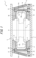
FIG. 1 is a cross-sectional view of a mold for forming a tire according to an embodiment of this disclosure, which is illustrated in a front view; -
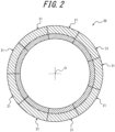
FIG. 2 is a cross-sectional view of the tread molding part illustrated inFIG. 1 , which is illustrated in a planar view; -
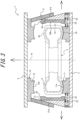
FIG. 3 is a cross-sectional view of the mold for forming the tire illustrated inFIG. 1 when the mold for forming the tire is opened, which is illustrated in a front view; -
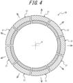
FIG. 4 is a cross-sectional view of the tread molding part illustrated inFIG. 1 when the tread molding part is opened, which is illustrated in a planar view; -
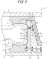
FIG. 5 is an enlarged cross-sectional view of detailed structure of the main portion of the mold for forming the tire illustrated inFIG. 1 , which is illustrated in a front view; -
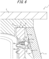
FIG. 6 is an enlarged cross-sectional view of the structure of the extrusion member and the cam member illustrated inFIG. 5 , which is illustrated in a front view; -
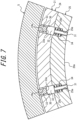
FIG. 7 is an enlarged cross-sectional view of the structure of the extrusion member and the cam member illustrated inFIG. 5 , which is illustrated in a planar view; and -
FIG. 8 is a cross-sectional view of the state of the extrusion member and the cam member when the tread molding part begins to be opened, which is illustrated in a front view. - By way of example, a mold for forming a tire and a tire production method according to an embodiment of this disclosure will now be described in detail with reference to the drawings. In this regard, common members and portions appearing in the drawings have the same reference signs.
- A mold for forming a
tire 1 illustrated inFIG. 1 according to an embodiment of this disclosure is for use in forming an unvulcanized (before vulcanization) raw tire based on a synthetic rubber into a predetermined shape with the raw tire being vulcanized to produce atire 2. - In this regard, the
tire 2 is a hollow tire based on a synthetic rubber including a pair ofsidewalls tread 2c, and is shaped to provide the interior of thetire 2 with a space for filling of a gas such as air or nitrogen. - The mold for forming the
tire 1 includes asidewall molding part 10 and atread molding part 20. - For example, the
sidewall molding part 10 can include an annular lowersidewall molding part 11 fixed to a top surface of alower container 3, and an annular uppersidewall molding part 12 fixed to a bottom surface of anupper container 4. - The
sidewall molding part 10 can dispose (accommodate) anannular tire 2 or a raw tire between the lowersidewall molding part 11 and the uppersidewall molding part 12 to be in an orientation by which the central axis of the raw tire becomes coaxial with the central axis O of thesidewall molding part 10. The lowersidewall molding part 11 includes a lowersidewall design surface 11a, which is in the form of a ring around the central axis O and is oriented toward the upward direction. The lowersidewall molding part 11 can form an outer surface of asidewall 2a of one of thetire 2 or the raw tire (any of which is oriented toward the downward direction inFIG. 1 ) by the lowersidewall design surface 11a. Similarly, the uppersidewall molding part 12 includes an uppersidewall design surface 12a, which is in the form of a ring around the central axis O and is oriented toward the downward direction. The uppersidewall molding part 12 can form an outer surface of asidewall 2b of the other of thetire 2 or the raw tire (any of which is oriented toward the upward direction inFIG. 1 ) by the uppersidewall design surface 12a. As illustrated inFIG. 3 , by moving theupper container 4 upwardly (the direction in which theupper container 4 and thelower container 3 is moved away from each other along the central axis of the tire 2) and relatively to thelower container 3, thesidewall molding part 10 is opened and thetire 2 is released from thesidewall molding part 10. By moving theupper container 4 downwardly to its original position illustrated inFIG. 1 , the sidewall moldingpart 10 in an opened configuration is closed to allow for forming of thetire 2 or the raw tire. - In this regard, modifications can be made to the configuration of the
sidewall molding part 10 as appropriate, and examples of such modifications include a configuration in which thesidewall molding part 10 is opened by moving thelower container 3 downwardly and relatively to theupper container 4. - The
tread molding part 20 is annular and coaxial with thesidewall molding part 10 and is disposed adjacent to a radially outer side of the lowersidewall molding part 11 and the uppersidewall molding part 12. The inner circumferential surface oriented toward the radially inner side of thetread molding part 20 is atread design surface 20a for forming an outer circumferential surface of thetread 2c of thetire 2. - As illustrated in
FIG. 2 , thetread molding part 20 is divided into a plurality ofsegments 21 arranged in a circumferential direction. Each of thesegments 21 is in the form of arc in a planar view and thesegments 21 are combined in a circumferentially arranged manner to constitute atread molding part 20, which is an annular mold as a whole. In this embodiment, thetread molding part 20 is divided into ninesegments 21 having the same length in a circumferential direction. In this regard, the division number of the tread moldingpart 20 in a circumferential direction is preferably, but not limited to, 7 to 13 and can be changed as appropriate. - As illustrated in
FIG. 1 , each of thesegments 21 is supported by aguide rail 22 extending in a radial direction of thesegment 21, and theguide rail 22 is supported by thelower container 3 and the lowersidewall molding part 11. As a result, each of thesegments 21 can be moved in a radial direction centered on the axis of the tread molding part 20 (central axis O). Thetread molding part 20 can be opened and closed by moving each of thesegments 21 in a radial direction. - More particularly, the outer circumferential surface of each of the
segments 21 oriented toward the radially outer side is provided with atapered surface 21a inclined in such a way that the outer diameter of thetapered surface 21a gradually becomes smaller toward the upward direction. Theouter ring 5 is annular and fixed to the bottom surface of theupper container 4 to be disposed the radially outer side of thesegment 21. The inner circumferential surface of theouter ring 5 oriented toward the radially inner side is provided with atapered surface 5a inclined in such a way that the outer diameter of thetapered surface 5a gradually becomes smaller toward the upward direction. Theouter ring 5 is coupled with each of thesegments 21, for example, by using a guide member (not illustrated) in such a way that thetapered surface 5a slides along thetapered surface 21a of thesegment 21 in an up-down direction. Also, aspring member 23 is disposed between each of thesegments 21 and the lowersidewall molding part 11, and each of thesegments 21 is biased toward the radially outer side by thespring member 23 corresponding to each of thesegments 21. - When
upper container 4 is moved upwardly and relatively to thelower container 3, theouter ring 5 is moved toward the side of the upward direction, that is, one side of the axial direction of the tread moldingpart 20 relatively to each of thesegments 21 with thetapered surface 5a being sliding along thetapered surface 21a of thesegment 21. As a result of this, as illustrated inFIGs. 3 and4 , each of thesegments 21 is driven by theouter ring 5 and also biased byspring member 23 to move toward the radially inner side centered on the axis of thetread molding part 20. In consequence, thetread molding part 20 is opened to be in a position at which thetread design surface 20a is separated from thetread 2c of thetire 2 or the raw tire When theupper container 4 is moved downwardly to its original position illustrated inFIG. 1 , thetread molding part 20 is moved downwardly to a position adjacent to the lowersidewall molding part 11. Subsequently, theouter ring 5 is moved downwardly in relation to each of thesegments 21, and each of thesegments 21 is moved toward the radially inner side centered on the axis of thetread molding part 20. As a result of this, as illustrated inFIGs. 1 and2 , each of thesegments 21 is driven by theouter ring 5 to move toward the radially inner side, and thetread molding part 20 is closed to allow for forming of thetire 2 or the raw tire. - As described above, in the mold for forming the
tire 1 of this embodiment, the annulartread molding part 20 is divided into a plurality ofsegments 21 arranged in a circumferential direction, and is configured to be opened and closed by moving each of thesegments 21 in a radial direction. - The mold for forming the
tire 1 includes abladder 6 which is disposed in the interior of the raw tire and expanded by supplying of pressurized steam. Also, the mold for forming thetire 1 includes a heater (not illustrated) for heating thesidewall molding part 10 and thetread molding part 20. The location of the heater can be determined as appropriate. - As illustrated in
FIG. 5 , in the mold for forming thetire 1 of this embodiment, each of the plurality of thesegments 21 constituting thetread molding part 20 includes aholder 24 and a design surface dividingmold part 25. - The
holder 24 is a portion to be driven toward a radial direction by theouter ring 5 when thetread molding part 20 is opened and closed, and the outer circumferential surface of theholder 24 constitutes atapered surface 21a. Theholder 24 can be formed, for example, by cutting a block made of metal such as low carbon steel. - The design surface dividing
mold part 25 is a portion which constitutes atread design surface 20a for forming thetread 2c of thetire 2, and a surface oriented toward the radially inner side constitutes a circumferentially divided portion of thetread design surface 20a. The design surface dividingmold part 25 is disposed on the radially inner side of theholder 24 and is fixed to theholder 24 by using a fixing member such as a bolt (not illustrated). - The design surface dividing
mold part 25 can be configured in such a way that thetread design surface 20a is provided with a plurality ofprojections 26 which protrudes in a radial direction from thetread design surface 20a toward the radially inner side. The plurality of theprojections 26 are used to form, for example, grooves or sipes which constitute a tread pattern, on thetread 2c of thetire 2 in vulcanization molding. The plurality of theprojections 26 can be of various shapes or sizes (length) tailored to the tread pattern, such as a plurality ofprojections 26 extending in a tire width direction and a plurality ofprojections 26 extending in a tire circumferential direction. In this regard, thetread design surface 20a may not be provided with theprojections 26. - The design surface dividing
mold part 25 is preferably formed by casting of a metal material having high thermal conductivity such as, for example, an aluminum alloy. In this case, for example, rib-shaped or blade-shapedprojections 26 made of steel can be provided by integrating with the design surface dividingmold part 25 in casting of the design surface dividingmold part 25. - Each of the
segments 21 is provided with anextrusion member 30 which protrudes from atread design surface 20a for forming of atread 2c of thetire 2 when thetread molding part 20 is opened after vulcanization molding of thetire 2 to press thetread 2c of thetire 2 after the vulcanization molding. - It is also possible that a plurality of
extrusion members 30 are provided in each of thesegments 21 in a manner spaced apart in a circumferential direction. In this embodiment, as illustrated inFIG. 7 , each of thesegments 21 is provided with twoextrusion members 30 in a manner spaced apart in a circumferential direction. - As illustrated in
FIGs. 6 and7 , for the purpose of supporting theextrusion member 30, the design surface dividingmold part 25 is provided with a throughhole 25a extending through the design surface dividingmold part 25 in a radial direction. The portion, which is open into the radially outer side, of the throughhole 25a is ahole 25b and the diameter of thehole 25b is larger than the diameter of the portion, which is open into the radially inner side, of the throughhole 25a. Theholder 24 is provided with anotch 24a which is extends through theholder 24 in the closing direction and extends to the upper end of theholder 24. Thehole 25b is open into thenotch 24a. - In this embodiment, the
extrusion member 30 is in the form of pin including arod 31 and ahead 32. Therod 31 is inserted into the throughhole 25a and thehead 32 is disposed in thehole 25b, and as a result, theextrusion member 30 is supported by the design surface dividingmold part 25 to be movable in a radial direction. A portion of thehead 32 is protruded from thehole 25b toward the interior of thenotch 24a of theholder 24. - A
spring member 34 is disposed between thehead 32 and the bottom surface of thehole 25b. Theextrusion member 30 is biased toward the radially outer side by thespring member 34. - A
cam member 33 is fixed to the inner circumferential surface of theouter ring 5. Thecam member 33 includes aflat surface portion 33a, which is parallel to the axis of thetread molding part 20 and oriented toward the radially inner side, and aninclined surface portion 33b, which is continuous with the lower end of theflat surface portion 33a and inclined toward the radially inner side. Thecam member 33 is disposed in the interior of thenotch 24a of theholder 24. In the situation where thetread molding part 20 is closed, theflat surface portion 33a of thecam member 33 abuts, from the radially outer side, thehead 32 constituting the rear end of theextrusion member 30. As a result of this, in the situation where thetread molding part 20 is closed, theextrusion member 30 is retained at a position at which thehead 32 abuts theflat surface portion 33a of thecam member 33 and the front end, oriented toward the radially inner side, of therod 31 is flush with thetread design surface 20a. - When the
outer ring 5 is moved in a direction of the axis of the tread molding part 20 (the upward direction inFIGs. 5 and6 ) relatively to thesegment 21 to open thetread molding part 20, thecam member 33 drives theextrusion member 30 in a direction to protrude from thetread design surface 20a. In other words, when theouter ring 5 is moved upwardly and relatively to thesegment 21 to open thetread molding part 20 inFIGs. 5 and6 , thecam member 33 is moved, together with theouter ring 5 in relation to the axial direction of theextrusion member 30, in the upward direction perpendicular to theextrusion member 30. When thecam member 33 is moved upwardly and relatively to theextrusion member 30, thehead 32 of theextrusion member 30 is moved along theinclined surface portion 33b and anextrusion member 30 is driven toward the radially inner side by thecam member 33. Theextrusion member 30 driven by thecam member 33 is moved toward the radially inner side with thespring member 34 being elastically deformed. As a result of such movement, the front end of therod 31 protrudes from thetread design surface 20a to the exterior of the design surface dividingmold part 25. - The
extrusion member 30 is preferably disposed to protrude from a position located one-sidedly on one side of thetread design surface 20a in a direction of the axis (central axis O) of thetread molding part 20 in relation to the center of thetread design surface 20a in the direction of the axis of thetread molding part 20. In this embodiment, as illustrated inFIG. 5 , theextrusion member 30 is disposed to protrude from a position which is located on the side of the upward direction in relation to the center of thetread design surface 20a in the up-down direction (width direction of the tire 2) and at which theextrusion member 30 faces an end of thetread 2c on the side of thesidewall 2b. - Next, a method for vulcanization molding of a raw tire to produce a
tire 2 having a predetermined shape by using a mold for forming atire 1 having the above-described configuration, that is, a tire production method as an embodiment of this disclosure will be described. - First of all, a
sidewall molding part 10 and atread molding part 20 are opened to dispose a raw tire in the interior of a mold for forming atire 1, and subsequently, thesidewall molding part 10 and thetread molding part 20 are closed. - Next, a
bladder 7 is expanded by supplying pressurized steam to thebladder 7 disposed in the interior of the raw tire. As a result, sidewalls of the raw tire are pressed against a lowersidewall design surface 11a and an uppersidewall design surface 12a of thesidewall molding part 10, respectively, and a tread is pressed against atread design surface 20a of thetread molding part 20. In this situation, a heater is used to heat thesidewall molding part 10 and thetread molding part 20, and such heat causes vulcanization of the synthetic rubber constituting the raw tire to form atire 2 having a predetermined shape. - After forming of the
tire 2 is completed, thesidewall molding part 10 and thetread molding part 20 are opened to remove a formedtire 2. - When each of the
segments 21 is moved toward the radially outer side to open thetread molding part 20 after vulcanization molding of thetire 2, as illustrated inFIG. 8 , theextrusion member 30 is driven by acam member 33 provided on theouter ring 5 to protrude from the tread design surface 20c, and thetire 2 after the vulcanization molding is released from thetread molding part 20 with thetread 2c being pressed by theextrusion member 30. As a result of this, by using a portion pressed by theextrusion member 30 as the starting point, thetread 2c of thetire 2 in close contact with the tread design surface 20c is gradually released from the tread design surface 20c. In consequence, mold releasing resistance of thetread 2c of thetire 2 from thetread design surface 20a in the initial stage of mold releasing of thetire 2 can be reduced. - As described above, in the tire production method by using the mold for forming the
tire 1 of this embodiment, when thetread molding part 20 is opened by moving each of thesegments 21 toward the radially outer side, thetire 2 is released from thetread molding part 20 with theextrusion member 30 being protruded from thetread design surface 20a for forming thetread 2c of thetire 2 and thetread 2c of thetire 2 after the vulcanization molding being pressed by theextrusion member 30. Therefore, mold releasing resistance of thetread 2c of thetire 2 from thetread design surface 20a in the initial stage of mold releasing of thetire 2 is reduced, and thus, force required for mold releasing of thetread 2c of thetire 2 from thetread design surface 20a can be reduced. Also, driving force applied to thesegments 21 in mold releasing of thetire 2 can be reduced, and as a result, the entire production device including the mold for forming thetire 1 can be downsized to reduce the production costs. In addition, mold releasing resistance of thetread 2c of thetire 2 from thetread design surface 20a can be reduced, and as a result, the generation of residual strain (permanent deformation) in thetire 2 after the mold releasing can be suppressed to improve the initial performance of thetire 2. - In particular, in this embodiment, the
extrusion member 30 is disposed to protrude from a position located one-sidedly on one side of the tread design surface 20c in a direction of the axis of thetread molding part 20 in relation to the center of the tread design surface 20c in the direction of the axis of thetread molding part 20. Therefore, by using a portion pressed by theextrusion member 30 as the starting point, thetread 2c of thetire 2 in close contact with the tread design surface 20c is gradually released from the tread design surface 20c, and in addition, outside air is gradually introduced between thetread 2c and thetread design surface 20a from the portion. As a result, force required for the initial stage of mold releasing of thetread 2c of thetire 2 from thetread design surface 20a can be further reduced. - Also, in this embodiment, the mold for forming the
tire 1 includes anouter ring 5 which is moved along atapered surface 21a provided in thesegment 21 in an axial direction of thetread molding part 20 relatively to thesegment 21 to drive thesegment 21 toward a radially outer side; and acam member 33 which is fixed to theouter ring 5 and abuts a rear end (head 32) of theextrusion member 30 and when theouter ring 5 is moved in a direction of the axis of thetread molding part 20 relatively to thesegment 21, drives theextrusion member 30 in a direction to be protruded from the tread design surface 20c. Therefore, when theouter ring 5 is activated to start mold releasing of thetire 2 from thetread molding part 20, theextrusion member 30 protrudes from the tread design surface 20c with the operation of theouter ring 5. In consequence, thetread 2c of thetire 2 can be released reliably from thetread design surface 20a by theextrusion member 30 in the initial stage of mold releasing of thetire 2. - In addition, in this embodiment, each of the
segments 21 is provided with a plurality ofextrusion members 30 in a manner spaced apart in a circumferential direction. Therefore, at each of thesegments 21, a plurality of places in thetread 2c of thetire 2 after the vulcanization molding are pressed by a plurality ofextrusion members 30 to release thetire 2 can be released more reliably from thetread molding part 20. In particular, in the case where a plurality ofextrusion members 30 is disposed to protrude from a position located one-sidedly on one side of the tread design surface 20c in a direction of the axis of thetread molding part 20 in relation to the center of the tread design surface 20c in the direction of the axis of thetread molding part 20, thetire 2 is released from thetread molding part 20 by using the entirety of thetread 2c of thetire 2 on one side in a tire width direction as the starting point in the initial stage of mold releasing. In consequent, in the initial stage of mold releasing of thetire 2, force required for mold releasing of thetread 2c of thetire 2 from thetread design surface 20a can be further reduced. - The mold for forming the
tire 1 of this embodiment can be configured in such a way that whentread molding part 20 is opened after vulcanization molding of thetire 2, an extrusion member (first extrusion member) 30 provided in one segment (first segment) 21 of a plurality ofsegments 21 protrudes from a tread design surface (first tread design surface) 20a provided in thesegment 21, and subsequently, an extrusion member (second extrusion member) 30 provided in another segment (second segment) 21 of the plurality of thesegments 21 protrudes from a tread design surface (second a tread design surface) 20a provided in thesegment 21. In other words, anextrusion member 30 disposed in each ofsegments 21 can be protruded from atread design surface 20a in such a way that theextrusion members 30 disposed in therespective segments 21 are sequentially activated at different times. In this case, theextrusion members 30 can be protruded, in a circumferentially sequential manner, from the tread design surface 20c in such a way that anextrusion member 30 of onesegment 21 is protruded from atread design surface 20a, and subsequently, anextrusion member 30 of asegment 21 adjacent to thesegment 21 is protruded from thetread design surface 20a, and then, anextrusion member 30 of asegment 21 adjacent to thesegment 21 is protruded from thetread design surface 20a. As a result of the above-described configuration, in the initial stage of mold releasing of thetire 2, thetread 2c is released from thetread design surface 20a in such a way that portions of thetread 2c is released sequentially in a circumferential direction. In consequence, thetread 2c of thetire 2 can be released from thetread design surface 20a by more small driving force. - As a matter of course, this disclosure is not limited to the above-described embodiment and a variety of modifications are possible without departing from the scope of this disclosure.
- For example, the above-described embodiment, each of the
segments 21 is provided with theholder 24, the design surface dividingmold part 25 is fixed to theholder 24, and theholder 24 is driven by theouter ring 5. However, theholder 24 can be integrated with the design surface dividingmold part 25. - Also, the number of the
extrusion member 30 provided in each of thesegments 21 can be changed as appropriate. Also, the shape of theextrusion member 30 and configuration of driving theextrusion member 30 can be changed as appropriate. -
- 1
- Mold for forming a tire
- 2
- Tire
- 2a
- Sidewall
- 2b
- Sidewall
- 2c
- Tread
- 3
- Lower container
- 4
- Upper container
- 5
- Outer ring
- 5a:
- tapered surface
- 6
- Bladder
- 10
- Sidewall molding part
- 11
- Lower sidewall molding part
- 11a
- Lower sidewall design surface
- 12
- Upper sidewall molding part
- 12a
- Upper sidewall design surface
- 20
- Tread molding part
- 20a
- Tread design surface
- 21
- Segment
- 21a
- Tapered surface
- 22
- Guide rail
- 23
- Spring member
- 24
- Holder
- 24a
- Notch
- 25
- Design surface dividing mold part
- 25a
- Through hole
- 25b
- Hole
- 26
- Projection
- 30
- Extrusion member
- 31
- Rod
- 32
- Head
- 33
- Cam member
- 33a
- Flat surface portion
- 33b
- Inclined surface portion
- 34
- Spring member
- O
- Central axis
Claims (6)
- A mold for forming a tire for vulcanization molding of an unvulcanized raw tire into a tire, the mold comprising:an annular tread molding part which is divided into a plurality of segments arranged in a circumferential direction and which is configured to be opened and closed by moving each of the segments in a radial direction, whereineach of the segments includesan extrusion member which protrudes from a tread design surface for forming a tread of the tire when the tread molding part is opened after vulcanization molding of the tire to press the tread of the tire after the vulcanization molding.
- The mold for forming the tire according to claim 1, the mold comprising:an outer ring which is moved along a tapered surface provided in the segment in an axial direction of the tread molding part relatively to the segment to drive the segment toward a radially outer side; anda cam member which is fixed to the outer ring and abuts a rear end of the extrusion member and when the outer ring is moved in a direction of the axis relatively to the segment, drives the extrusion member in a direction to protrude from the tread design surface.
- The mold for forming the tire according to claim 1 or 2, wherein the extrusion member is disposed to protrude from a position located one-sidedly on one side of the tread design surface in a direction of an axis of the tread molding part in relation to the center of the tread design surface in the direction of the axis of the tread molding part.
- The mold for forming the tire according to the any one of claims 1 to 3, wherein
each of the segments is provided with the plurality of the extrusion members in a manner spaced apart in a circumferential direction. - The mold for forming the tire according to any one of claims 1 to 4, wherein
when the tread molding part is opened after vulcanization molding of the tire, the first extrusion member provided in the first segment protrudes from the first tread design surface, and subsequently, the second extrusion member provided in the second segment protrudes from the second tread design surface. - A tire production method for vulcanization molding of an unvulcanized raw tire to produce a tire by using a mold for forming a tire comprising an annular tread molding part which is divided into a plurality of segments arranged in a circumferential direction and which is configured to be opened and closed by moving each of the segments in the radial direction, wherein
when each of the segments is moved toward a radially outer side to open the tread molding part, an extrusion member is protruded from a tread design surface for forming a tread of the tire to release the tire from the tread molding part with the tread of the tire after the vulcanization molding being pressed by the extrusion member.
Applications Claiming Priority (2)
| Application Number | Priority Date | Filing Date | Title |
|---|---|---|---|
| JP2021103649A JP7577616B2 (en) | 2021-06-22 | 2021-06-22 | Tire molding mold and tire manufacturing method |
| PCT/JP2021/043051 WO2022269942A1 (en) | 2021-06-22 | 2021-11-24 | Tire molding mold and tire manufacturing method |
Publications (3)
| Publication Number | Publication Date |
|---|---|
| EP4360846A1 true EP4360846A1 (en) | 2024-05-01 |
| EP4360846A4 EP4360846A4 (en) | 2024-10-30 |
| EP4360846B1 EP4360846B1 (en) | 2025-12-31 |
Family
ID=84544368
Family Applications (1)
| Application Number | Title | Priority Date | Filing Date |
|---|---|---|---|
| EP21947221.4A Active EP4360846B1 (en) | 2021-06-22 | 2021-11-24 | TIRE SHAPE AND TIRE MANUFACTURING PROCESS |
Country Status (5)
| Country | Link |
|---|---|
| US (1) | US12583195B2 (en) |
| EP (1) | EP4360846B1 (en) |
| JP (1) | JP7577616B2 (en) |
| CN (1) | CN117425553A (en) |
| WO (1) | WO2022269942A1 (en) |
Family Cites Families (15)
| Publication number | Priority date | Publication date | Assignee | Title |
|---|---|---|---|---|
| US5066448A (en) | 1990-10-03 | 1991-11-19 | The Goodyear Tire & Rubber Company | Tread removal method and apparatus |
| JPH08142057A (en) | 1994-11-17 | 1996-06-04 | Sumitomo Rubber Ind Ltd | Tire vulcanization mold |
| JP2000102927A (en) * | 1998-09-29 | 2000-04-11 | Bridgestone Corp | Tire vulcanization molding die and tire vulcanization molding method |
| JP4191294B2 (en) | 1998-10-22 | 2008-12-03 | 株式会社ブリヂストン | Tire vulcanization mold and vulcanization molding method |
| JP3810585B2 (en) | 1999-05-18 | 2006-08-16 | 三菱重工業株式会社 | Tire vulcanizer |
| JP4138153B2 (en) | 1999-05-31 | 2008-08-20 | 三菱重工業株式会社 | Tire mold segment drive device |
| JP4603709B2 (en) | 2001-03-05 | 2010-12-22 | 株式会社ブリヂストン | Tire vulcanization mold and tire manufacturing method |
| JP2006341415A (en) | 2005-06-08 | 2006-12-21 | Bridgestone Corp | Tire release method and tire vulcanizing apparatus |
| ITTO20060532A1 (en) | 2006-07-19 | 2008-01-20 | Bridgestone Corp | VULCANIZATION MOLD FOR A TIRE |
| US7572120B2 (en) | 2007-12-20 | 2009-08-11 | The Goodyear Tire & Rubber Company | Tire mold |
| JP5185801B2 (en) * | 2008-12-25 | 2013-04-17 | 住友ゴム工業株式会社 | Tire vulcanization mold |
| BRPI1005653A2 (en) | 2009-12-17 | 2012-03-13 | The Goodyear Tire & Rubber Company | tire mold and tire with inner tire tread grooves |
| JP2011140192A (en) | 2010-01-08 | 2011-07-21 | Bridgestone Corp | Apparatus and method for manufacturing annular member |
| KR101370972B1 (en) * | 2012-07-13 | 2014-03-07 | 주식회사 엠케이테크놀로지 | Tire curing mould of draw improvement type |
| FR2998830B1 (en) | 2012-12-04 | 2015-02-20 | Michelin & Cie | COOKING MOLD OF PNEUMATIC ENVELOPE BRAKE INCLUDING MOBILE SECTORS |
-
2021
- 2021-06-22 JP JP2021103649A patent/JP7577616B2/en active Active
- 2021-11-24 WO PCT/JP2021/043051 patent/WO2022269942A1/en not_active Ceased
- 2021-11-24 CN CN202180099055.0A patent/CN117425553A/en active Pending
- 2021-11-24 US US18/563,180 patent/US12583195B2/en active Active
- 2021-11-24 EP EP21947221.4A patent/EP4360846B1/en active Active
Also Published As
| Publication number | Publication date |
|---|---|
| WO2022269942A1 (en) | 2022-12-29 |
| JP2023002405A (en) | 2023-01-10 |
| JP7577616B2 (en) | 2024-11-05 |
| US12583195B2 (en) | 2026-03-24 |
| EP4360846B1 (en) | 2025-12-31 |
| US20240269947A1 (en) | 2024-08-15 |
| CN117425553A (en) | 2024-01-19 |
| EP4360846A4 (en) | 2024-10-30 |
Similar Documents
| Publication | Publication Date | Title |
|---|---|---|
| EP4360843B1 (en) | TIRE FORMING TOOL AND TIRE MANUFACTURING PROCESS | |
| EP4360847A1 (en) | Tire molding mold and tire manufacturing method | |
| BRPI0721631A2 (en) | vehicle wheel tire molding and vulcanizing apparatus, and process for controlling a detachment of the mold sectors of the vulcanized tires in a vulcanizing mold | |
| US12583195B2 (en) | Mold for forming a tire and tire production method | |
| EP4360845A1 (en) | Tire molding mold and tire manufacturing method | |
| EP4360844B1 (en) | Tire molding die and tire production method | |
| EP4427903A1 (en) | Tire molding mold and tire manufacturing method | |
| JP2020062787A (en) | Tire vulcanizing device | |
| US7959424B2 (en) | Tyre curing mold | |
| JP6617437B2 (en) | Method and apparatus for manufacturing tire vulcanizing bladder | |
| CN114364523B (en) | Mould for tyre shaping | |
| US20260061713A1 (en) | Curing mold and method for curing a green tire | |
| JP2025089129A (en) | Tire molding mold | |
| JP4788254B2 (en) | Tire vulcanization mold |
Legal Events
| Date | Code | Title | Description |
|---|---|---|---|
| STAA | Information on the status of an ep patent application or granted ep patent |
Free format text: STATUS: THE INTERNATIONAL PUBLICATION HAS BEEN MADE |
|
| PUAI | Public reference made under article 153(3) epc to a published international application that has entered the european phase |
Free format text: ORIGINAL CODE: 0009012 |
|
| STAA | Information on the status of an ep patent application or granted ep patent |
Free format text: STATUS: REQUEST FOR EXAMINATION WAS MADE |
|
| 17P | Request for examination filed |
Effective date: 20231125 |
|
| AK | Designated contracting states |
Kind code of ref document: A1 Designated state(s): AL AT BE BG CH CY CZ DE DK EE ES FI FR GB GR HR HU IE IS IT LI LT LU LV MC MK MT NL NO PL PT RO RS SE SI SK SM TR |
|
| DAV | Request for validation of the european patent (deleted) | ||
| DAX | Request for extension of the european patent (deleted) | ||
| A4 | Supplementary search report drawn up and despatched |
Effective date: 20240926 |
|
| RIC1 | Information provided on ipc code assigned before grant |
Ipc: B29D 30/06 20060101ALI20240920BHEP Ipc: B29L 30/00 20060101ALI20240920BHEP Ipc: B29C 35/02 20060101ALI20240920BHEP Ipc: B29C 33/44 20060101ALI20240920BHEP Ipc: B29C 33/02 20060101AFI20240920BHEP |
|
| GRAP | Despatch of communication of intention to grant a patent |
Free format text: ORIGINAL CODE: EPIDOSNIGR1 |
|
| STAA | Information on the status of an ep patent application or granted ep patent |
Free format text: STATUS: GRANT OF PATENT IS INTENDED |
|
| RIC1 | Information provided on ipc code assigned before grant |
Ipc: B29C 33/02 20060101AFI20250625BHEP Ipc: B29C 33/44 20060101ALI20250625BHEP Ipc: B29C 35/02 20060101ALI20250625BHEP Ipc: B29L 30/00 20060101ALI20250625BHEP Ipc: B29D 30/06 20060101ALI20250625BHEP |
|
| RIC1 | Information provided on ipc code assigned before grant |
Ipc: B29C 33/02 20060101AFI20250707BHEP Ipc: B29C 33/44 20060101ALI20250707BHEP Ipc: B29C 35/02 20060101ALI20250707BHEP Ipc: B29D 30/06 20060101ALI20250707BHEP Ipc: B29L 30/00 20060101ALN20250707BHEP |
|
| INTG | Intention to grant announced |
Effective date: 20250724 |
|
| GRAS | Grant fee paid |
Free format text: ORIGINAL CODE: EPIDOSNIGR3 |
|
| P01 | Opt-out of the competence of the unified patent court (upc) registered |
Free format text: CASE NUMBER: UPC_APP_9422_4360846/2025 Effective date: 20251009 |
|
| GRAA | (expected) grant |
Free format text: ORIGINAL CODE: 0009210 |
|
| STAA | Information on the status of an ep patent application or granted ep patent |
Free format text: STATUS: THE PATENT HAS BEEN GRANTED |
|
| AK | Designated contracting states |
Kind code of ref document: B1 Designated state(s): AL AT BE BG CH CY CZ DE DK EE ES FI FR GB GR HR HU IE IS IT LI LT LU LV MC MK MT NL NO PL PT RO RS SE SI SK SM TR |
|
| REG | Reference to a national code |
Ref country code: CH Ref legal event code: F10 Free format text: ST27 STATUS EVENT CODE: U-0-0-F10-F00 (AS PROVIDED BY THE NATIONAL OFFICE) Effective date: 20251231 Ref country code: GB Ref legal event code: FG4D |
|
| REG | Reference to a national code |
Ref country code: DE Ref legal event code: R096 Ref document number: 602021045819 Country of ref document: DE |
|
| REG | Reference to a national code |
Ref country code: IE Ref legal event code: FG4D |
|
| REG | Reference to a national code |
Ref country code: LT Ref legal event code: MG9D |
|
| PG25 | Lapsed in a contracting state [announced via postgrant information from national office to epo] |
Ref country code: NO Free format text: LAPSE BECAUSE OF FAILURE TO SUBMIT A TRANSLATION OF THE DESCRIPTION OR TO PAY THE FEE WITHIN THE PRESCRIBED TIME-LIMIT Effective date: 20260331 |
|
| PG25 | Lapsed in a contracting state [announced via postgrant information from national office to epo] |
Ref country code: FI Free format text: LAPSE BECAUSE OF FAILURE TO SUBMIT A TRANSLATION OF THE DESCRIPTION OR TO PAY THE FEE WITHIN THE PRESCRIBED TIME-LIMIT Effective date: 20251231 Ref country code: HR Free format text: LAPSE BECAUSE OF FAILURE TO SUBMIT A TRANSLATION OF THE DESCRIPTION OR TO PAY THE FEE WITHIN THE PRESCRIBED TIME-LIMIT Effective date: 20251231 |
|
| PG25 | Lapsed in a contracting state [announced via postgrant information from national office to epo] |
Ref country code: RS Free format text: LAPSE BECAUSE OF FAILURE TO SUBMIT A TRANSLATION OF THE DESCRIPTION OR TO PAY THE FEE WITHIN THE PRESCRIBED TIME-LIMIT Effective date: 20260331 |
|
| PG25 | Lapsed in a contracting state [announced via postgrant information from national office to epo] |
Ref country code: LV Free format text: LAPSE BECAUSE OF FAILURE TO SUBMIT A TRANSLATION OF THE DESCRIPTION OR TO PAY THE FEE WITHIN THE PRESCRIBED TIME-LIMIT Effective date: 20251231 |
|
| PG25 | Lapsed in a contracting state [announced via postgrant information from national office to epo] |
Ref country code: BG Free format text: LAPSE BECAUSE OF FAILURE TO SUBMIT A TRANSLATION OF THE DESCRIPTION OR TO PAY THE FEE WITHIN THE PRESCRIBED TIME-LIMIT Effective date: 20251231 |
|
| REG | Reference to a national code |
Ref country code: NL Ref legal event code: MP Effective date: 20251231 |
|
| REG | Reference to a national code |
Ref country code: AT Ref legal event code: MK05 Ref document number: 1872744 Country of ref document: AT Kind code of ref document: T Effective date: 20251231 |
|
| PG25 | Lapsed in a contracting state [announced via postgrant information from national office to epo] |
Ref country code: NL Free format text: LAPSE BECAUSE OF FAILURE TO SUBMIT A TRANSLATION OF THE DESCRIPTION OR TO PAY THE FEE WITHIN THE PRESCRIBED TIME-LIMIT Effective date: 20251231 |
|
| PG25 | Lapsed in a contracting state [announced via postgrant information from national office to epo] |
Ref country code: LT Free format text: LAPSE BECAUSE OF FAILURE TO SUBMIT A TRANSLATION OF THE DESCRIPTION OR TO PAY THE FEE WITHIN THE PRESCRIBED TIME-LIMIT Effective date: 20251231 |
|
| PG25 | Lapsed in a contracting state [announced via postgrant information from national office to epo] |
Ref country code: SM Free format text: LAPSE BECAUSE OF FAILURE TO SUBMIT A TRANSLATION OF THE DESCRIPTION OR TO PAY THE FEE WITHIN THE PRESCRIBED TIME-LIMIT Effective date: 20251231 |
|
| PG25 | Lapsed in a contracting state [announced via postgrant information from national office to epo] |
Ref country code: ES Free format text: LAPSE BECAUSE OF FAILURE TO SUBMIT A TRANSLATION OF THE DESCRIPTION OR TO PAY THE FEE WITHIN THE PRESCRIBED TIME-LIMIT Effective date: 20251231 |
|
| PG25 | Lapsed in a contracting state [announced via postgrant information from national office to epo] |
Ref country code: PL Free format text: LAPSE BECAUSE OF FAILURE TO SUBMIT A TRANSLATION OF THE DESCRIPTION OR TO PAY THE FEE WITHIN THE PRESCRIBED TIME-LIMIT Effective date: 20251231 |
|
| PG25 | Lapsed in a contracting state [announced via postgrant information from national office to epo] |
Ref country code: IT Free format text: LAPSE BECAUSE OF FAILURE TO SUBMIT A TRANSLATION OF THE DESCRIPTION OR TO PAY THE FEE WITHIN THE PRESCRIBED TIME-LIMIT Effective date: 20251231 |
|
| PG25 | Lapsed in a contracting state [announced via postgrant information from national office to epo] |
Ref country code: AT Free format text: LAPSE BECAUSE OF FAILURE TO SUBMIT A TRANSLATION OF THE DESCRIPTION OR TO PAY THE FEE WITHIN THE PRESCRIBED TIME-LIMIT Effective date: 20251231 |
|
| PG25 | Lapsed in a contracting state [announced via postgrant information from national office to epo] |
Ref country code: EE Free format text: LAPSE BECAUSE OF FAILURE TO SUBMIT A TRANSLATION OF THE DESCRIPTION OR TO PAY THE FEE WITHIN THE PRESCRIBED TIME-LIMIT Effective date: 20251231 |
|
| PG25 | Lapsed in a contracting state [announced via postgrant information from national office to epo] |
Ref country code: PT Free format text: LAPSE BECAUSE OF FAILURE TO SUBMIT A TRANSLATION OF THE DESCRIPTION OR TO PAY THE FEE WITHIN THE PRESCRIBED TIME-LIMIT Effective date: 20260430 Ref country code: IS Free format text: LAPSE BECAUSE OF FAILURE TO SUBMIT A TRANSLATION OF THE DESCRIPTION OR TO PAY THE FEE WITHIN THE PRESCRIBED TIME-LIMIT Effective date: 20260430 |
|
| PG25 | Lapsed in a contracting state [announced via postgrant information from national office to epo] |
Ref country code: CZ Free format text: LAPSE BECAUSE OF FAILURE TO SUBMIT A TRANSLATION OF THE DESCRIPTION OR TO PAY THE FEE WITHIN THE PRESCRIBED TIME-LIMIT Effective date: 20251231 |
|
| PG25 | Lapsed in a contracting state [announced via postgrant information from national office to epo] |
Ref country code: SK Free format text: LAPSE BECAUSE OF FAILURE TO SUBMIT A TRANSLATION OF THE DESCRIPTION OR TO PAY THE FEE WITHIN THE PRESCRIBED TIME-LIMIT Effective date: 20251231 |
|
| PG25 | Lapsed in a contracting state [announced via postgrant information from national office to epo] |
Ref country code: SE Free format text: LAPSE BECAUSE OF FAILURE TO SUBMIT A TRANSLATION OF THE DESCRIPTION OR TO PAY THE FEE WITHIN THE PRESCRIBED TIME-LIMIT Effective date: 20251231 |