EP4360845A1 - Tire molding mold and tire manufacturing method - Google Patents
Tire molding mold and tire manufacturing method Download PDFInfo
- Publication number
- EP4360845A1 EP4360845A1 EP21947220.6A EP21947220A EP4360845A1 EP 4360845 A1 EP4360845 A1 EP 4360845A1 EP 21947220 A EP21947220 A EP 21947220A EP 4360845 A1 EP4360845 A1 EP 4360845A1
- Authority
- EP
- European Patent Office
- Prior art keywords
- tire
- tread
- molding part
- mold
- segments
- Prior art date
- Legal status (The legal status is an assumption and is not a legal conclusion. Google has not performed a legal analysis and makes no representation as to the accuracy of the status listed.)
- Granted
Links
Images



Classifications
-
- B—PERFORMING OPERATIONS; TRANSPORTING
- B29—WORKING OF PLASTICS; WORKING OF SUBSTANCES IN A PLASTIC STATE IN GENERAL
- B29C—SHAPING OR JOINING OF PLASTICS; SHAPING OF MATERIAL IN A PLASTIC STATE, NOT OTHERWISE PROVIDED FOR; AFTER-TREATMENT OF THE SHAPED PRODUCTS, e.g. REPAIRING
- B29C33/00—Moulds or cores; Details thereof or accessories therefor
- B29C33/20—Opening, closing or clamping
- B29C33/26—Opening, closing or clamping by pivotal movement
-
- B—PERFORMING OPERATIONS; TRANSPORTING
- B29—WORKING OF PLASTICS; WORKING OF SUBSTANCES IN A PLASTIC STATE IN GENERAL
- B29D—PRODUCING PARTICULAR ARTICLES FROM PLASTICS OR FROM SUBSTANCES IN A PLASTIC STATE
- B29D30/00—Producing pneumatic or solid tyres or parts thereof
- B29D30/06—Pneumatic tyres or parts thereof (e.g. produced by casting, moulding, compression moulding, injection moulding, centrifugal casting)
- B29D30/0601—Vulcanising tyres; Vulcanising presses for tyres
- B29D30/0606—Vulcanising moulds not integral with vulcanising presses
- B29D30/0629—Vulcanising moulds not integral with vulcanising presses with radially movable sectors
-
- B—PERFORMING OPERATIONS; TRANSPORTING
- B29—WORKING OF PLASTICS; WORKING OF SUBSTANCES IN A PLASTIC STATE IN GENERAL
- B29D—PRODUCING PARTICULAR ARTICLES FROM PLASTICS OR FROM SUBSTANCES IN A PLASTIC STATE
- B29D30/00—Producing pneumatic or solid tyres or parts thereof
- B29D30/06—Pneumatic tyres or parts thereof (e.g. produced by casting, moulding, compression moulding, injection moulding, centrifugal casting)
- B29D30/0601—Vulcanising tyres; Vulcanising presses for tyres
- B29D30/0606—Vulcanising moulds not integral with vulcanising presses
- B29D2030/0607—Constructional features of the moulds
- B29D2030/0612—Means for forming recesses or protrusions in the tyres, e.g. grooves or ribs, to create the tread or sidewalls patterns
-
- B—PERFORMING OPERATIONS; TRANSPORTING
- B29—WORKING OF PLASTICS; WORKING OF SUBSTANCES IN A PLASTIC STATE IN GENERAL
- B29D—PRODUCING PARTICULAR ARTICLES FROM PLASTICS OR FROM SUBSTANCES IN A PLASTIC STATE
- B29D30/00—Producing pneumatic or solid tyres or parts thereof
- B29D30/06—Pneumatic tyres or parts thereof (e.g. produced by casting, moulding, compression moulding, injection moulding, centrifugal casting)
- B29D30/0601—Vulcanising tyres; Vulcanising presses for tyres
- B29D30/0606—Vulcanising moulds not integral with vulcanising presses
- B29D30/0629—Vulcanising moulds not integral with vulcanising presses with radially movable sectors
- B29D2030/0631—Means for forcing adjacent mould sectors away one from another, e.g. using springs or the like, to create repulsive forces
-
- B—PERFORMING OPERATIONS; TRANSPORTING
- B29—WORKING OF PLASTICS; WORKING OF SUBSTANCES IN A PLASTIC STATE IN GENERAL
- B29L—INDEXING SCHEME ASSOCIATED WITH SUBCLASS B29C, RELATING TO PARTICULAR ARTICLES
- B29L2030/00—Pneumatic or solid tyres or parts thereof
Definitions
- This disclosure relates to a mold for forming a tire and a tire production method.
- an annular tread molding part for forming a tread of a tire is divided into a plurality of segments arranged in a circumferential direction and is configured to be opened and closed by moving each of the segments in a radial direction (for example, see PTLs 1 to 3).
- each of the segments is moved toward a radially outer side with maintaining the orientation of each of the segments to a tread of the tire.
- all portions of the tread design surface for forming the tread of the segment are to peel off from the tread simultaneously. Therefore, there has been a problem in that a great driving force is required for driving the segments in the initial stage of mold releasing of the tire.
- This disclosure has been accomplished in view of the above-described problem and it is an object of this disclosure to provide a mold for forming a tire and a tire production method which can reduce driving force required for driving the segments in the initial stage of mold releasing of the tire.
- the mold for forming the tire of this disclosure is a mold for forming a tire for vulcanization molding of an unvulcanized raw tire into a tire, the mold including an annular tread molding part which is divided into a plurality of segments arranged in a circumferential direction and which is configured to be opened and closed by moving each of the segments in a radial direction, wherein each of the segments includes a design surface dividing mold part which includes a tread design surface for forming a tread of the tire and which is configured to rotate around a rotatable shaft perpendicular to a direction of movement of the segments and also to an axis of the tread molding part when the tread molding part is opened after vulcanization molding of the tire.
- the mold for forming the tire of this disclosure can be configured in such a way that each of the segments includes a holder to be driven toward a radially outer side by a container when the tread molding part is opened, the design surface dividing mold part is fixed to a radially inner side of the holder, and the holder is supported by the rotatable shaft to be rotatable in relation to the container.
- the mold for forming the tire of this disclosure can be configured in such a way that the rotatable shaft is disposed on a radially outer side in a one-sided manner in relation to the center of the holder in the radial direction, and on one side in a direction of the axis of the tread molding part in relation to the center of the holder in the direction of the axis of the tread molding part.
- the mold for forming the tire of this disclosure can be configured to include a spring member which is attached between the holder and the container corresponding to the spring member to retain the design surface dividing mold part corresponding to the spring member at a predetermined position, and when the tread molding part is opened, elastically deforms to allow for rotation of the holder in relation to the container.
- the tire production method of this disclosure is a tire production method for vulcanization molding of an unvulcanized raw tire to produce a tire by using a mold for forming a tire including an annular tread molding part which is divided into a plurality of segments arranged in a circumferential direction and which is configured to be opened and closed by moving each of the segments in a radial direction, wherein when each of the segments is moved toward a radially outer side to open the tread molding part, the tire is released from the tread molding part with a design surface dividing mold part provided on the segment being rotated around a rotatable shaft perpendicular to a direction of movement of the segments and also to an axis of the tread molding part.
- This disclosure can provide a mold for forming a tire and a tire production method which can reduce driving force required for driving the segments in the initial stage of mold releasing of the tire.
- a mold for forming a tire 1 illustrated in FIG. 1 is for use in forming an unvulcanized (before vulcanization) raw tire based on a synthetic rubber into a predetermined shape with the raw tire being vulcanized to produce a tire 2.
- the tire 2 is a hollow tire based on a synthetic rubber including a pair of sidewalls 2a, 2b and a tread 2c, and is shaped to provide the interior of the tire 2 with a space for filling of a gas such as air or nitrogen.
- the mold for forming the tire 1 includes a sidewall molding part 10 and a tread molding part 20.
- the sidewall molding part 10 can include an annular lower sidewall molding part 11 fixed to a top surface of a lower container 3, and an annular upper sidewall molding part 12 fixed to a bottom surface of an upper container 4.
- the sidewall molding part 10 can dispose (accommodate) an annular tire 2 or a raw tire between the lower sidewall molding part 11 and the upper sidewall molding part 12 to be in an orientation by which the central axis of the raw tire becomes coaxial with the central axis O of the sidewall molding part 10.
- the lower sidewall molding part 11 includes a lower sidewall design surface 11a, which is in the form of a ring around the central axis O and is oriented toward the upward direction.
- the lower sidewall molding part 11 can form an outer surface of a sidewall 2a of one of the tire 2 and the raw tire (any of which is oriented toward the downward direction in FIG. 1 ) by the lower sidewall design surface 11a.
- the upper sidewall molding part 12 includes an upper sidewall design surface 12a, which is in the form of a ring around the central axis O and is oriented toward the downward direction.
- the upper sidewall molding part 12 can form an outer surface of a sidewall 2b of the other of the tire 2 and the raw tire (any of which is oriented toward the upward direction in FIG. 1 ) by the upper sidewall design surface 12a.
- the sidewall molding part 10 is opened and the tire 2 is released from the sidewall molding part 10.
- the sidewall molding part 10 in an opened configuration is closed to allow for forming of the tire 2 or the raw tire.
- modifications can be made to the configuration of the sidewall molding part 10 as appropriate, and examples of such modifications include a configuration in which the sidewall molding part 10 is opened by moving the lower container 3 downwardly and relatively to the upper container 4.
- the tread molding part 20 is annular and coaxial with the sidewall molding part 10 and is disposed adjacent to a radially outer side of the lower sidewall molding part 11 and the upper sidewall molding part 12.
- the inner circumferential surface, oriented toward the radially inner side, of the tread molding part 20 is a tread design surface 20a for forming an outer circumferential surface of the tread 2c of the tire 2.
- the tread molding part 20 is divided into a plurality of segments arranged in a circumferential direction 21.
- Each of the segments 21 is in the form of arc in a planar view and the segments 21 are combined in a circumferentially arranged manner to constitute a tread molding part 20, which is an annular mold as a whole.
- the tread molding part 20 is divided into nine segments 21 having the same length in a circumferential direction.
- the division number of the tread molding part 20 in a circumferential direction is preferably, but not limited to, 7 to 13 and can be changed as appropriate.
- an outer circumferential surface, oriented toward the radially outer side, of each of the segments 21 is fixed to the interior of intermediate container 5 corresponding to each of the segments 21, and each of the segments 21 is driven by the intermediate container 5 to move toward a radial direction centered on the axis of the tread molding part 20 (central axis O).
- the tread molding part 20 can be opened and closed by moving each of the segments 21 in a radial direction.
- the outer circumferential surface of the intermediate container 5 oriented toward the radially outer side is provided with a tapered surface 5a inclined in such a way that the outer diameter of the tapered surface 5a gradually becomes smaller toward the upward direction.
- an annular outer ring 6 disposed on the radially outer side of the intermediate container 5 is fixed.
- the inner circumferential surface of the outer ring 6 oriented toward the radially inner side is provided with a tapered surface 6a inclined in such a way that the outer diameter of the tapered surface 6a gradually becomes smaller toward the upward direction.
- the outer ring 6 is coupled with each of the intermediate containers 5, for example, by using a guide member (not illustrated) in such a way that the tapered surface 6a slides along the tapered surface 5a of the intermediate container 5 in an up-down direction.
- each of the intermediate containers 5 is moved toward the radially outer side centered on the axis of the tread molding part 20.
- each of the segments 21 is driven by an intermediate container 5 corresponding to each of the segments 21 to move, together with the intermediate container 5, toward the radially outer side.
- the tread molding part 20 is opened to be in a position at which the tread design surface 20a is separated from the tread 2c of the tire 2 or the raw tire.
- the tread molding part 20 can be configured in such a way that, after the tread molding part 20 is opened as described above, the tread molding part 20 suspended by the outer ring 6 is moved upwardly together with the upper container 4 to a position (an upper position in relation to the position illustrated in FIG. 3 ) at which the tire 2 after forming can be removed.
- the tread molding part 20 is moved downwardly to a position adjacent to the lower sidewall molding part 11.
- each of the segments 21 is driven by the intermediate container 5 corresponding to each of the segments 21 to move, together with the intermediate container 5, toward the radially inner side, and the tread molding part 20 is closed to allow for forming of the tire 2 or the raw tire.
- the annular tread molding part 20 is divided into a plurality of segments 21 arranged in a circumferential direction, and is configured to be opened and closed by moving each of the segments 21 in a radial direction.
- the opening and closing mechanism of the tread molding part 20 is not limited to a configuration using the outer ring 6 but various configurations can be employed.
- the mold for forming the tire 1 includes a bladder 7 which is disposed in the interior of the raw tire and expanded by supplying of pressurized steam. Also, the mold for forming the tire 1 includes a heater (not illustrated) for heating the sidewall molding part 10 and the tread molding part 20. The location of the heater can be determined as appropriate.
- each of the plurality of the segments 21 constituting the tread molding part 20 include a design surface dividing mold part 23.
- each of the segments 21 include a holder 22.
- the design surface dividing mold part 23 is disposed on the radially inner side of the holder 22 and is fixed to the holder 22 by using a fixing member such as a bolt (not illustrated).
- the holder 22 is a portion which is driven toward the radially outer side by the intermediate container 5 when the tread molding part 20 is opened. When the tread molding part 20 is closed, the holder 22 is driven toward the radially inner side by the intermediate container 5.
- the holder 22 can be formed, for example, by cutting a block made of metal such as low carbon steel.
- the design surface dividing mold part 23 is a portion which constitutes a tread design surface 20a for forming the tread 2c of the tire 2. As illustrated in FIG. 6 , the design surface dividing mold part 23 is in the form of arc in a planar view and a surface oriented toward the radially inner side constitutes a circumferentially divided portion of the tread design surface 20a.
- the design surface dividing mold part 23 can be configured in such a way that the tread design surface 20a is provided with a plurality of projections 24 which protrude in a radial direction from the tread design surface 20a toward the radially inner side.
- the plurality of the projections 24 are used to form, for example, grooves or sips, which constitute a tread pattern, on the tread 2c of the tire 2 in vulcanization molding.
- the plurality of the projections 24 can be of various shapes or sizes (length) tailored to the tread pattern, such as a plurality of projections 24 extending in a tire width direction and a plurality of projections 24 extending in a tire circumferential direction.
- the tread design surface 20a may not be provided with the projections 24.
- the design surface dividing mold part 23 is preferably formed by casting of a metal material having high thermal conductivity such as, for example, an aluminum alloy.
- a metal material having high thermal conductivity such as, for example, an aluminum alloy.
- rib-shaped or blade-shaped projections 24 made of steel can be provided by integrating with the design surface dividing mold part 23 in casting of the design surface dividing mold part 23.
- the design surface dividing mold part 23 is configured to rotate around the rotatable shaft 25 perpendicular to a direction of movement of the segments 21 and also to an axis (central axis O) of the tread molding part 20 when the tread molding part 20 is opened after vulcanization molding of the tire 2.
- the holder 22 is supported by the rotatable shaft 25 perpendicular to (parallel to a direction tangential to the tire 2) a direction of movement of the segments 21 and also to an axis of the tread molding part 20 to be rotatable in relation to the intermediate container 5.
- the design surface dividing mold part 23 is configured to rotate, together with the holder 22, around the rotatable shaft 25 in relation to the intermediate container 5.
- the rotatable shaft 25 is disposed on a radially outer side in a one-sided manner in relation to the center of the holder 22 in the radial direction, and on one side in a direction of the axis of the tread molding part 20 (in FIG. 5 , the upper side) in relation to the center of the holder 22 in the direction of the axis of the tread molding part 20.
- an upper end of a back surface of the holder 22 oriented toward the radially outer side is provided with a recess 22a.
- An upper end of the surface of the intermediate container 5 oriented toward the radially inner side is provided integrally with a protrusion 5b protruding toward the radially inner side.
- the protrusion 5b is disposed in the interior of the recess 22a.
- the rotatable shaft 25 extends through a protrusion 5b disposed in the interior of the recess 22a with both ends of the rotatable shaft 25 being supported by the holder 22.
- the holder 22 is supported by the rotatable shaft 25 extending through the protrusion 5b of the intermediate container 5 to be rotatable in relation to the intermediate container 5.
- the holder 22 and the design surface dividing mold part 23 are configured to rotate, from a predetermined position, around a rotatable shaft 25 perpendicular to a direction of movement of the segments 21 and also to an axis of the tread molding part 20 in relation to the intermediate container 5 in such a way that the lower end side is moved toward the radially inner side in relation to the upper end side on which the rotatable shaft 25 is disposed when the tread molding part 20 is opened after vulcanization molding of the tire 2.
- predetermined position refers to a position at which the design surface dividing mold part 23 is in an orientation by which a tread design surface 20a provided on a design surface dividing mold part 23 is continuously connected, in a circumferentially arranged manner, with a tread design surface 20a provided on a design surface dividing mold part 23 of another segment 21.
- the tread molding part 20 can be configured to include a spring member 27 which is attached between the holder 22 and the intermediate container 5 corresponding to the spring member 27 to retain the design surface dividing mold part 23 corresponding to the spring member 27 at a predetermined position, and when the tread molding part 20 is opened, elastically deforms to allow for rotation of the holder 22 in relation to the intermediate container 5.
- a bolt 28 is fixed to the back surface of the holder 22 and a spring member 27 is disposed between a head 28a of the bolt 28 disposed in a hole 5c provided in the intermediate container 5 and a bottom wall of the hole 5c in the intermediate container 5.
- the spring member 27 is a helical compression spring.
- the spring member 27 biases a portion of the holder at a distance from the rotatable shaft 25 22 toward a direction in which the portion is attracted toward the intermediate container 5.
- the spring member 27 retains the design surface dividing mold part 23 fixed to the holder 22 at a predetermined position together with a holder 22, and when the tread molding part 20 is opened, elastically deforms between the head 28a of the bolt 28 and the bottom wall of the hole 5c to allow for rotation of the design surface dividing mold part 23 fixed to the holder 22 in relation to the intermediate container 5.
- a sidewall molding part 10 and a tread molding part 20 are opened to dispose a raw tire in the interior of a mold for forming a tire 1, and subsequently, the sidewall molding part 10 and the tread molding part 20 are closed.
- a bladder 7 is expanded by supplying pressurized steam to the bladder 7 disposed in the interior of the raw tire.
- sidewalls of the raw tire are pressed against a lower sidewall design surface 11a and an upper sidewall design surface 12a of the sidewall molding part 10, respectively, and a tread is pressed against a tread design surface 20a of the tread molding part 20.
- a heater is used to heat the sidewall molding part 10 and the tread molding part 20, and such heat causes vulcanization of the synthetic rubber constituting the raw tire to form a tire 2 having a predetermined shape.
- the sidewall molding part 10 and the tread molding part 20 are opened to remove a formed tire 2.
- the design surface dividing mold part 23 spontaneously rotates (panning action), together with the holder 22, around the rotatable shaft 25 perpendicular to a direction of movement of the segments 21 and also to an axis of the tread molding part 20 in relation to the intermediate container 5 in such a way that the lower end side is moved toward the radially inner side in relation to the upper end side on which is disposed the rotatable shaft 25.
- the tire 2 when the tread molding part 20 is opened after vulcanization molding of the tire 2, the tire 2 can be released from the tread molding part 20 with the design surface dividing mold part 23 being rotated around the rotatable shaft 25 perpendicular to the direction of movement of the segments 21 and also to an axis of the tread molding part 20.
- the tread 2c of the tire 2 is gradually released from the side of one end (in FIG. 8 , the upper end side) of the design surface dividing mold part 23 in a width direction of the tire 2, followed by releasing from the side of the other end (in FIG. 8 , the lower end side).
- mold releasing resistance of the tread 2c of the tire 2 from the tread design surface 20a can be reduced, and as a result, the generation of residual strain (permanent deformation) in the tire 2 after the mold releasing can be suppressed to improve the initial performance of the tire 2.
- the rotatable shaft 25 is disposed on a radially outer side in a one-sided manner in relation to the center of the radial direction of the holder 22, and on one side in a direction of the axis of the tread molding part 20 in relation to the center of the holder 22 in the direction of the axis of the tread molding part 20. Therefore, driving force for moving the segments 21 toward the radially outer side is disproportionately applied to the side of one end of the holder 22 or the design surface dividing mold part 23 in a width direction of the tire 2. As a result, when the tread molding part 20 is opened after vulcanization molding of the tire 2, the design surface dividing mold part 23 can spontaneously rotate around the rotatable shaft 25 more reliably. Therefore, driving force required for driving the segments 21 in the initial stage of mold releasing of the tire 2 can be reduced more reliably.
- each of the design surface dividing mold parts 23 rotates around the rotatable shaft 25 to reduce undercut resistance of the tread 2c of the tire 2 caused by the projections 24.
- driving force required for driving the segments 21 in the initial stage of mold releasing of the tire 2 can be further reduced.
- defects such as permanent deformation in the formed tread 2c of the tire 2 and the failure of the projections 24 can be suppressed by preventing excessively high undercut resistance.
- the tread molding part 20 includes the spring member 27 which is attached between the holder 22 and the intermediate container 5 corresponding to the spring member 27 to retain the design surface dividing mold part 23 corresponding to the spring member 27 at a predetermined position, and when the tread molding part 20 is opened, elastically deforms to allow for rotation of the holder 22 in relation to the intermediate container 5.
- the design surface dividing mold part 23 is ensured to be retained at a predetermined position in vulcanization molding of a raw tire to improve the formability of the tire 2.
- the design surface dividing mold part 23 can spontaneously rotate, together with the holder 22, around the rotatable shaft 25 in relation to the intermediate container 5. In consequence, force required for mold releasing of the tread 2c of the tire 2 from the tread design surface 20a in the initial stage of mold releasing of the tire 2 can be reduced more reliably.
- each of the segments 21 is provided with the holder 22, the design surface dividing mold part 23 is fixed to the holder 22, and the holder 22 is supported by the rotatable shaft 25 to be rotatable in relation to the intermediate container 5.
- the holder 22 is not provided, and the design surface dividing mold part 23 is supported on the intermediate container 5 by the rotatable shaft 25.
- the positions of the rotatable shaft 25 can be possible as long as the position of the rotatable shaft 25 is a position by which the design surface dividing mold part 23 spontaneously rotates around the rotatable shaft 25 when the tread molding part 20 is opened after vulcanization molding of the tire 2.
Landscapes
- Engineering & Computer Science (AREA)
- Mechanical Engineering (AREA)
- Heating, Cooling, Or Curing Plastics Or The Like In General (AREA)
- Moulds For Moulding Plastics Or The Like (AREA)
Abstract
Description
- This disclosure relates to a mold for forming a tire and a tire production method.
- In a known conventional mold for forming a tire for use in vulcanization molding of an unvulcanized raw tire to produce a tire, it is known that an annular tread molding part (a tread mold) for forming a tread of a tire is divided into a plurality of segments arranged in a circumferential direction and is configured to be opened and closed by moving each of the segments in a radial direction (for example, see PTLs 1 to 3).
-
- PTL 1:
JP 2000-326332 A - PTL 2:
JP 2000-334740 A - PTL 3:
JP 2009-149079 A - However, in the above-described conventional mold for forming a tire or the above-described conventional tire production method, when the tire is released from the tread molding part after vulcanization molding, each of the segments is moved toward a radially outer side with maintaining the orientation of each of the segments to a tread of the tire. As a result, all portions of the tread design surface for forming the tread of the segment are to peel off from the tread simultaneously. Therefore, there has been a problem in that a great driving force is required for driving the segments in the initial stage of mold releasing of the tire.
- This disclosure has been accomplished in view of the above-described problem and it is an object of this disclosure to provide a mold for forming a tire and a tire production method which can reduce driving force required for driving the segments in the initial stage of mold releasing of the tire.
- The mold for forming the tire of this disclosure is a mold for forming a tire for vulcanization molding of an unvulcanized raw tire into a tire, the mold including an annular tread molding part which is divided into a plurality of segments arranged in a circumferential direction and which is configured to be opened and closed by moving each of the segments in a radial direction, wherein each of the segments includes a design surface dividing mold part which includes a tread design surface for forming a tread of the tire and which is configured to rotate around a rotatable shaft perpendicular to a direction of movement of the segments and also to an axis of the tread molding part when the tread molding part is opened after vulcanization molding of the tire.
- In an embodiment, the mold for forming the tire of this disclosure can be configured in such a way that each of the segments includes a holder to be driven toward a radially outer side by a container when the tread molding part is opened, the design surface dividing mold part is fixed to a radially inner side of the holder, and the holder is supported by the rotatable shaft to be rotatable in relation to the container.
- In an embodiment, the mold for forming the tire of this disclosure can be configured in such a way that the rotatable shaft is disposed on a radially outer side in a one-sided manner in relation to the center of the holder in the radial direction, and on one side in a direction of the axis of the tread molding part in relation to the center of the holder in the direction of the axis of the tread molding part.
- In an embodiment, the mold for forming the tire of this disclosure can be configured to include a spring member which is attached between the holder and the container corresponding to the spring member to retain the design surface dividing mold part corresponding to the spring member at a predetermined position, and when the tread molding part is opened, elastically deforms to allow for rotation of the holder in relation to the container.
- The tire production method of this disclosure is a tire production method for vulcanization molding of an unvulcanized raw tire to produce a tire by using a mold for forming a tire including an annular tread molding part which is divided into a plurality of segments arranged in a circumferential direction and which is configured to be opened and closed by moving each of the segments in a radial direction, wherein when each of the segments is moved toward a radially outer side to open the tread molding part, the tire is released from the tread molding part with a design surface dividing mold part provided on the segment being rotated around a rotatable shaft perpendicular to a direction of movement of the segments and also to an axis of the tread molding part.
- This disclosure can provide a mold for forming a tire and a tire production method which can reduce driving force required for driving the segments in the initial stage of mold releasing of the tire.
- In the accompanying drawings:
-
FIG. 1 is a cross-sectional view of a mold for forming a tire according to an embodiment of this disclosure, which is illustrated in a front view; -
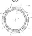
FIG. 2 is a cross-sectional view of the tread molding part illustrated inFIG. 1 , which is illustrated in a planar view; -
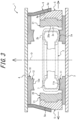
FIG. 3 is a cross-sectional view of the mold for forming the tire illustrated inFIG. 1 when the mold for forming the tire is opened, which is illustrated in a front view; -
FIG. 4 is a cross-sectional view of the tread molding part illustrated inFIG. 1 when the tread molding part is opened, which is illustrated in a planar view; -
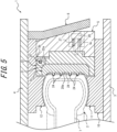
FIG. 5 is an enlarged cross-sectional view of detailed structure of the main portion of the mold for forming the tire illustrated inFIG. 1 , which is illustrated in a front view; -
FIG. 6 is a cross-sectional view of one segment and an intermediate container illustrated inFIG. 5 in a planar view; -
FIG. 7 is a cross-sectional view illustrating the details of the spring member illustrated inFIG. 5 ; and -
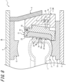
FIG. 8 is a cross-sectional view illustrating one segment illustrated inFIG. 5 in mold releasing of the tire, which is illustrated in a planar view. - By way of example, a mold for forming a tire and a tire production method according to an embodiment of this disclosure will now be described in detail with reference to the drawings. In this regard, common members and portions appearing in the drawings have the same reference signs.
- A mold for forming a tire 1 illustrated in
FIG. 1 according to an embodiment of this disclosure is for use in forming an unvulcanized (before vulcanization) raw tire based on a synthetic rubber into a predetermined shape with the raw tire being vulcanized to produce atire 2. - In this regard, the
tire 2 is a hollow tire based on a synthetic rubber including a pair ofsidewalls tread 2c, and is shaped to provide the interior of thetire 2 with a space for filling of a gas such as air or nitrogen. - The mold for forming the tire 1 includes a
sidewall molding part 10 and atread molding part 20. - For example, the
sidewall molding part 10 can include an annular lowersidewall molding part 11 fixed to a top surface of alower container 3, and an annular uppersidewall molding part 12 fixed to a bottom surface of anupper container 4. - The
sidewall molding part 10 can dispose (accommodate) anannular tire 2 or a raw tire between the lowersidewall molding part 11 and the uppersidewall molding part 12 to be in an orientation by which the central axis of the raw tire becomes coaxial with the central axis O of thesidewall molding part 10. The lowersidewall molding part 11 includes a lowersidewall design surface 11a, which is in the form of a ring around the central axis O and is oriented toward the upward direction. The lowersidewall molding part 11 can form an outer surface of asidewall 2a of one of thetire 2 and the raw tire (any of which is oriented toward the downward direction inFIG. 1 ) by the lowersidewall design surface 11a. Similarly, the uppersidewall molding part 12 includes an uppersidewall design surface 12a, which is in the form of a ring around the central axis O and is oriented toward the downward direction. The uppersidewall molding part 12 can form an outer surface of asidewall 2b of the other of thetire 2 and the raw tire (any of which is oriented toward the upward direction inFIG. 1 ) by the uppersidewall design surface 12a. As illustrated inFIG. 3 , by moving theupper container 4 upwardly (the direction in which theupper container 4 and thelower container 3 is moved away from each other along the central axis of the tire 2) and relatively to thelower container 3, thesidewall molding part 10 is opened and thetire 2 is released from thesidewall molding part 10. By moving theupper container 4 downwardly to its original position illustrated inFIG. 1 , the sidewall moldingpart 10 in an opened configuration is closed to allow for forming of thetire 2 or the raw tire. - In this regard, modifications can be made to the configuration of the
sidewall molding part 10 as appropriate, and examples of such modifications include a configuration in which thesidewall molding part 10 is opened by moving thelower container 3 downwardly and relatively to theupper container 4. - The
tread molding part 20 is annular and coaxial with thesidewall molding part 10 and is disposed adjacent to a radially outer side of the lowersidewall molding part 11 and the uppersidewall molding part 12. The inner circumferential surface, oriented toward the radially inner side, of thetread molding part 20 is atread design surface 20a for forming an outer circumferential surface of thetread 2c of thetire 2. - As illustrated in
FIG. 2 , thetread molding part 20 is divided into a plurality of segments arranged in acircumferential direction 21. Each of thesegments 21 is in the form of arc in a planar view and thesegments 21 are combined in a circumferentially arranged manner to constitute atread molding part 20, which is an annular mold as a whole. In this embodiment, thetread molding part 20 is divided into ninesegments 21 having the same length in a circumferential direction. In this regard, the division number of the tread moldingpart 20 in a circumferential direction is preferably, but not limited to, 7 to 13 and can be changed as appropriate. - As illustrated in
FIG. 1 , an outer circumferential surface, oriented toward the radially outer side, of each of thesegments 21 is fixed to the interior ofintermediate container 5 corresponding to each of thesegments 21, and each of thesegments 21 is driven by theintermediate container 5 to move toward a radial direction centered on the axis of the tread molding part 20 (central axis O). Thetread molding part 20 can be opened and closed by moving each of thesegments 21 in a radial direction. - More particularly, the outer circumferential surface of the
intermediate container 5 oriented toward the radially outer side is provided with atapered surface 5a inclined in such a way that the outer diameter of thetapered surface 5a gradually becomes smaller toward the upward direction. To the bottom surface of theupper container 4, an annularouter ring 6 disposed on the radially outer side of theintermediate container 5 is fixed. The inner circumferential surface of theouter ring 6 oriented toward the radially inner side is provided with atapered surface 6a inclined in such a way that the outer diameter of thetapered surface 6a gradually becomes smaller toward the upward direction. Theouter ring 6 is coupled with each of theintermediate containers 5, for example, by using a guide member (not illustrated) in such a way that thetapered surface 6a slides along thetapered surface 5a of theintermediate container 5 in an up-down direction. - When the
upper container 4 is moved upwardly and relatively to thelower container 3, theouter ring 6 is moved upwardly and relatively to each of theintermediate containers 5 with thetapered surface 6a being sliding along thetapered surface 5a of theintermediate container 5. As a result of this, as illustrated inFIG. 3 , each of theintermediate containers 5 is moved toward the radially outer side centered on the axis of thetread molding part 20. When each of theintermediate containers 5 is moved toward the radially outer side centered on the axis of thetread molding part 20, as illustrated inFIGs. 3 and4 , each of thesegments 21 is driven by anintermediate container 5 corresponding to each of thesegments 21 to move, together with theintermediate container 5, toward the radially outer side. As a result of this, thetread molding part 20 is opened to be in a position at which thetread design surface 20a is separated from thetread 2c of thetire 2 or the raw tire. In this regard, thetread molding part 20 can be configured in such a way that, after thetread molding part 20 is opened as described above, thetread molding part 20 suspended by theouter ring 6 is moved upwardly together with theupper container 4 to a position (an upper position in relation to the position illustrated inFIG. 3 ) at which thetire 2 after forming can be removed. When theupper container 4 is moved downwardly to its original position illustrated inFIG. 1 , thetread molding part 20 is moved downwardly to a position adjacent to the lowersidewall molding part 11. Subsequently, theouter ring 6 is moved downwardly in relation to each of theintermediate containers 5, and each of theintermediate containers 5 is moved toward the radially inner side centered on the axis of thetread molding part 20. As a result of this, as illustrated inFIGs. 1 and2 , each of thesegments 21 is driven by theintermediate container 5 corresponding to each of thesegments 21 to move, together with theintermediate container 5, toward the radially inner side, and thetread molding part 20 is closed to allow for forming of thetire 2 or the raw tire. - As described above, in the mold for forming the tire 1 of this embodiment, the annular
tread molding part 20 is divided into a plurality ofsegments 21 arranged in a circumferential direction, and is configured to be opened and closed by moving each of thesegments 21 in a radial direction. - The opening and closing mechanism of the
tread molding part 20 is not limited to a configuration using theouter ring 6 but various configurations can be employed. - The mold for forming the tire 1 includes a
bladder 7 which is disposed in the interior of the raw tire and expanded by supplying of pressurized steam. Also, the mold for forming the tire 1 includes a heater (not illustrated) for heating thesidewall molding part 10 and thetread molding part 20. The location of the heater can be determined as appropriate. - As illustrated in
FIGs. 5 and6 , in the mold for forming the tire 1 of this embodiment, each of the plurality of thesegments 21 constituting thetread molding part 20 include a design surface dividingmold part 23. - In this embodiment, each of the
segments 21 include aholder 22. The design surface dividingmold part 23 is disposed on the radially inner side of theholder 22 and is fixed to theholder 22 by using a fixing member such as a bolt (not illustrated). - The
holder 22 is a portion which is driven toward the radially outer side by theintermediate container 5 when thetread molding part 20 is opened. When thetread molding part 20 is closed, theholder 22 is driven toward the radially inner side by theintermediate container 5. Theholder 22 can be formed, for example, by cutting a block made of metal such as low carbon steel. - The design surface dividing
mold part 23 is a portion which constitutes atread design surface 20a for forming thetread 2c of thetire 2. As illustrated inFIG. 6 , the design surface dividingmold part 23 is in the form of arc in a planar view and a surface oriented toward the radially inner side constitutes a circumferentially divided portion of thetread design surface 20a. - As illustrated in
FIG. 5 , the design surface dividingmold part 23 can be configured in such a way that thetread design surface 20a is provided with a plurality ofprojections 24 which protrude in a radial direction from thetread design surface 20a toward the radially inner side. The plurality of theprojections 24 are used to form, for example, grooves or sips, which constitute a tread pattern, on thetread 2c of thetire 2 in vulcanization molding. The plurality of theprojections 24 can be of various shapes or sizes (length) tailored to the tread pattern, such as a plurality ofprojections 24 extending in a tire width direction and a plurality ofprojections 24 extending in a tire circumferential direction. In this regard, thetread design surface 20a may not be provided with theprojections 24. - The design surface dividing
mold part 23 is preferably formed by casting of a metal material having high thermal conductivity such as, for example, an aluminum alloy. In this case, for example, rib-shaped or blade-shapedprojections 24 made of steel can be provided by integrating with the design surface dividingmold part 23 in casting of the design surface dividingmold part 23. - The design surface dividing
mold part 23 is configured to rotate around therotatable shaft 25 perpendicular to a direction of movement of thesegments 21 and also to an axis (central axis O) of thetread molding part 20 when thetread molding part 20 is opened after vulcanization molding of thetire 2. - In this embodiment, the
holder 22 is supported by therotatable shaft 25 perpendicular to (parallel to a direction tangential to the tire 2) a direction of movement of thesegments 21 and also to an axis of thetread molding part 20 to be rotatable in relation to theintermediate container 5. The design surface dividingmold part 23 is configured to rotate, together with theholder 22, around therotatable shaft 25 in relation to theintermediate container 5. - Also, in this embodiment, the
rotatable shaft 25 is disposed on a radially outer side in a one-sided manner in relation to the center of theholder 22 in the radial direction, and on one side in a direction of the axis of the tread molding part 20 (inFIG. 5 , the upper side) in relation to the center of theholder 22 in the direction of the axis of thetread molding part 20. - More particularly, as illustrated in
FIG.s 5 and6 , an upper end of a back surface of theholder 22 oriented toward the radially outer side is provided with arecess 22a. An upper end of the surface of theintermediate container 5 oriented toward the radially inner side is provided integrally with aprotrusion 5b protruding toward the radially inner side. Theprotrusion 5b is disposed in the interior of therecess 22a. Therotatable shaft 25 extends through aprotrusion 5b disposed in the interior of therecess 22a with both ends of therotatable shaft 25 being supported by theholder 22. As a result of this, at therecess 22a, theholder 22 is supported by therotatable shaft 25 extending through theprotrusion 5b of theintermediate container 5 to be rotatable in relation to theintermediate container 5. - As a result of the above-described configuration, the
holder 22 and the design surface dividingmold part 23 are configured to rotate, from a predetermined position, around arotatable shaft 25 perpendicular to a direction of movement of thesegments 21 and also to an axis of thetread molding part 20 in relation to theintermediate container 5 in such a way that the lower end side is moved toward the radially inner side in relation to the upper end side on which therotatable shaft 25 is disposed when thetread molding part 20 is opened after vulcanization molding of thetire 2. In this regard, the term "predetermined position" refers to a position at which the design surface dividingmold part 23 is in an orientation by which atread design surface 20a provided on a design surface dividingmold part 23 is continuously connected, in a circumferentially arranged manner, with atread design surface 20a provided on a design surface dividingmold part 23 of anothersegment 21. - The
tread molding part 20 can be configured to include aspring member 27 which is attached between theholder 22 and theintermediate container 5 corresponding to thespring member 27 to retain the design surface dividingmold part 23 corresponding to thespring member 27 at a predetermined position, and when thetread molding part 20 is opened, elastically deforms to allow for rotation of theholder 22 in relation to theintermediate container 5. As illustrated inFIG. 7 , in this embodiment, abolt 28 is fixed to the back surface of theholder 22 and aspring member 27 is disposed between ahead 28a of thebolt 28 disposed in ahole 5c provided in theintermediate container 5 and a bottom wall of thehole 5c in theintermediate container 5. Thespring member 27 is a helical compression spring. Thespring member 27 biases a portion of the holder at a distance from therotatable shaft 25 22 toward a direction in which the portion is attracted toward theintermediate container 5. As a result, thespring member 27 retains the design surface dividingmold part 23 fixed to theholder 22 at a predetermined position together with aholder 22, and when thetread molding part 20 is opened, elastically deforms between thehead 28a of thebolt 28 and the bottom wall of thehole 5c to allow for rotation of the design surface dividingmold part 23 fixed to theholder 22 in relation to theintermediate container 5. - Next, a method for vulcanization molding of a raw tire to produce a
tire 2 having a predetermined shape by using a mold for forming a tire 1 having the above-described configuration, that is, a tire production method as an embodiment of this disclosure will be described. - First of all, a
sidewall molding part 10 and atread molding part 20 are opened to dispose a raw tire in the interior of a mold for forming a tire 1, and subsequently, thesidewall molding part 10 and thetread molding part 20 are closed. - Next, a
bladder 7 is expanded by supplying pressurized steam to thebladder 7 disposed in the interior of the raw tire. As a result, sidewalls of the raw tire are pressed against a lowersidewall design surface 11a and an uppersidewall design surface 12a of thesidewall molding part 10, respectively, and a tread is pressed against atread design surface 20a of thetread molding part 20. In this situation, a heater is used to heat thesidewall molding part 10 and thetread molding part 20, and such heat causes vulcanization of the synthetic rubber constituting the raw tire to form atire 2 having a predetermined shape. - After forming of the
tire 2 is completed, thesidewall molding part 10 and thetread molding part 20 are opened to remove a formedtire 2. - When each of the
segments 21 is moved toward the radially outer side to open thetread molding part 20 after vulcanization molding of thetire 2, driving force, which is required for resisting close contact of thetread 2c of thetire 2 with the inner circumferential surface of thetread design surface 20a and also for resisting undercut resistance caused between thetread 2c of thetire 2 and theprojections 24, is applied to each of the design surface dividingmold parts 23 by the medium of theholder 22. At this time, the design surface dividingmold part 23 in each of thesegments 21 is supported to be rotatable around therotatable shaft 25 in relation to theintermediate container 5 by the medium of theholder 22. Therefore, when thetread molding part 20 is opened after vulcanization molding of thetire 2, as illustrated inFIG. 8 , the design surface dividingmold part 23 spontaneously rotates (panning action), together with theholder 22, around therotatable shaft 25 perpendicular to a direction of movement of thesegments 21 and also to an axis of thetread molding part 20 in relation to theintermediate container 5 in such a way that the lower end side is moved toward the radially inner side in relation to the upper end side on which is disposed therotatable shaft 25. - As described above, in the method for producing the tire by using the mold for forming the tire 1 of this embodiment, when the
tread molding part 20 is opened after vulcanization molding of thetire 2, thetire 2 can be released from thetread molding part 20 with the design surface dividingmold part 23 being rotated around therotatable shaft 25 perpendicular to the direction of movement of thesegments 21 and also to an axis of thetread molding part 20. As a result of this, thetread 2c of thetire 2 is gradually released from the side of one end (inFIG. 8 , the upper end side) of the design surface dividingmold part 23 in a width direction of thetire 2, followed by releasing from the side of the other end (inFIG. 8 , the lower end side). Thus, outside air is gradually introduced between thetread 2c and thetread design surface 20a from the side of one end to allow for reducing mold releasing resistance of thetread 2c of thetire 2 from thetread design surface 20a in the initial stage of mold releasing of thetire 2. Therefore, force required for mold releasing of thetread 2c of thetire 2 from thetread design surface 20a in the initial stage of mold releasing of thetire 2 is reduced, and thus, driving force required for driving thesegments 21 in the initial stage of mold releasing of thetire 2 can be reduced. Also, driving force applied to thesegments 21 in mold releasing of thetire 2 can be reduced, and as a result, the entire production device including the mold for forming the tire 1 can be downsized to reduce the production costs. In addition, mold releasing resistance of thetread 2c of thetire 2 from thetread design surface 20a can be reduced, and as a result, the generation of residual strain (permanent deformation) in thetire 2 after the mold releasing can be suppressed to improve the initial performance of thetire 2. - In particular, in this embodiment, the
rotatable shaft 25 is disposed on a radially outer side in a one-sided manner in relation to the center of the radial direction of theholder 22, and on one side in a direction of the axis of thetread molding part 20 in relation to the center of theholder 22 in the direction of the axis of thetread molding part 20. Therefore, driving force for moving thesegments 21 toward the radially outer side is disproportionately applied to the side of one end of theholder 22 or the design surface dividingmold part 23 in a width direction of thetire 2. As a result, when thetread molding part 20 is opened after vulcanization molding of thetire 2, the design surface dividingmold part 23 can spontaneously rotate around therotatable shaft 25 more reliably. Therefore, driving force required for driving thesegments 21 in the initial stage of mold releasing of thetire 2 can be reduced more reliably. - Also, in mold releasing of the
tire 2 from thetread molding part 20, each of the design surface dividingmold parts 23 rotates around therotatable shaft 25 to reduce undercut resistance of thetread 2c of thetire 2 caused by theprojections 24. As a result, driving force required for driving thesegments 21 in the initial stage of mold releasing of thetire 2 can be further reduced. In addition, in mold releasing of thetire 2 from thetread molding part 20, defects such as permanent deformation in the formedtread 2c of thetire 2 and the failure of theprojections 24 can be suppressed by preventing excessively high undercut resistance. - In addition, in the mold for forming the tire 1 of this embodiment, the
tread molding part 20 includes thespring member 27 which is attached between theholder 22 and theintermediate container 5 corresponding to thespring member 27 to retain the design surface dividingmold part 23 corresponding to thespring member 27 at a predetermined position, and when thetread molding part 20 is opened, elastically deforms to allow for rotation of theholder 22 in relation to theintermediate container 5. As a result, the design surface dividingmold part 23 is ensured to be retained at a predetermined position in vulcanization molding of a raw tire to improve the formability of thetire 2. In addition, when thetread molding part 20 is opened after vulcanization molding of thetire 2, the design surface dividingmold part 23 can spontaneously rotate, together with theholder 22, around therotatable shaft 25 in relation to theintermediate container 5. In consequence, force required for mold releasing of thetread 2c of thetire 2 from thetread design surface 20a in the initial stage of mold releasing of thetire 2 can be reduced more reliably. - As a matter of course, this disclosure is not limited to the above-described embodiment and a variety of modifications are possible without departing from the scope of this disclosure.
- For example, in the above-described embodiment, each of the
segments 21 is provided with theholder 22, the design surface dividingmold part 23 is fixed to theholder 22, and theholder 22 is supported by therotatable shaft 25 to be rotatable in relation to theintermediate container 5. However, it is also possible that theholder 22 is not provided, and the design surface dividingmold part 23 is supported on theintermediate container 5 by therotatable shaft 25. - Also, a variety of the positions of the
rotatable shaft 25 can be possible as long as the position of therotatable shaft 25 is a position by which the design surface dividingmold part 23 spontaneously rotates around therotatable shaft 25 when thetread molding part 20 is opened after vulcanization molding of thetire 2. -
- 1
- Mold for forming a tire
- 2
- Tire
- 2a
- Sidewall
- 2b
- Sidewall
- 2c
- Tread
- 3
- Lower container
- 4
- Upper container
- 5
- Intermediate container
- 5a
- Tapered surface
- 5b
- Protrusion
- 5c
- Hole
- 6
- Outer ring
- 6a
- Tapered surface
- 7
- Bladder
- 10
- Sidewall molding part
- 11
- Lower sidewall molding part
- 11a
- Lower sidewall design surface
- 12
- Upper sidewall molding part
- 12a
- Upper sidewall design surface
- 20
- Tread molding part
- 20a
- Tread design surface
- 21
- Segment
- 22
- Holder
- 22a
- Recess
- 23
- Design surface dividing mold part
- 24
- Projection
- 25
- Rotatable shaft
- 27
- Spring member
- 28
- Bolt
- 28a
- Head
- O
- Central axis
Claims (5)
- A mold for forming a tire for vulcanization molding of an unvulcanized raw tire into a tire, the mold comprising:an annular tread molding part which is divided into a plurality of segments arranged in a circumferential direction and which is configured to be opened and closed by moving each of the segments in a radial direction, whereineach of the segments includesa design surface dividing mold part which includes a tread design surface for forming a tread of the tire and which is configured to rotate around a rotatable shaft perpendicular to a direction of movement of the segments and also to an axis of the tread molding part when the tread molding part is opened after vulcanization molding of the tire.
- The mold for forming the tire according to claim 1, whereineach of the segments includes a holder to be driven toward a radially outer side by a container when the tread molding part is opened,the design surface dividing mold part is fixed to a radially inner side of the holder, andthe holder is supported by the rotatable shaft to be rotatable in relation to the container.
- The mold for forming the tire according to claim 2, wherein
the rotatable shaft is disposed on a radially outer side in a one-sided manner in relation to the center of the holder in the radial direction, and on one side in a direction of the axis of the tread molding part in relation to the center of the holder in the direction of the axis of the tread molding part. - The mold for forming the tire according to claim 2 or 3, the mold comprising:
a spring member which is attached between the holder and the container corresponding to the spring member to retain the design surface dividing mold part corresponding to the spring member at a predetermined position, and when the tread molding part is opened, elastically deforms to allow for rotation of the holder in relation to the container. - A method for vulcanization molding of an unvulcanized raw tire to produce a tire by using a mold for forming a tire comprising an annular tread molding part which is divided into a plurality of segments arranged in a circumferential direction and which is configured to be opened and closed by moving each of the segments in a radial direction, wherein
when each of the segments is moved toward a radially outer side to open the tread molding part, the tire is released from the tread molding part with a design surface dividing mold part provided on the segment being rotated around a rotatable shaft perpendicular to a direction of movement of the segments and also to an axis of the tread molding part.
Applications Claiming Priority (2)
| Application Number | Priority Date | Filing Date | Title |
|---|---|---|---|
| JP2021103648A JP7649206B2 (en) | 2021-06-22 | 2021-06-22 | Tire molding mold and tire manufacturing method |
| PCT/JP2021/043049 WO2022269941A1 (en) | 2021-06-22 | 2021-11-24 | Tire molding mold and tire manufacturing method |
Publications (3)
| Publication Number | Publication Date |
|---|---|
| EP4360845A1 true EP4360845A1 (en) | 2024-05-01 |
| EP4360845A4 EP4360845A4 (en) | 2024-10-30 |
| EP4360845B1 EP4360845B1 (en) | 2026-01-07 |
Family
ID=84544336
Family Applications (1)
| Application Number | Title | Priority Date | Filing Date |
|---|---|---|---|
| EP21947220.6A Active EP4360845B1 (en) | 2021-06-22 | 2021-11-24 | Tire molding mold and tire manufacturing method |
Country Status (5)
| Country | Link |
|---|---|
| US (1) | US20240246307A1 (en) |
| EP (1) | EP4360845B1 (en) |
| JP (1) | JP7649206B2 (en) |
| CN (1) | CN117480041A (en) |
| WO (1) | WO2022269941A1 (en) |
Families Citing this family (1)
| Publication number | Priority date | Publication date | Assignee | Title |
|---|---|---|---|---|
| JP2025054797A (en) * | 2023-09-26 | 2025-04-08 | 株式会社ブリヂストン | Tire molding mold |
Family Cites Families (9)
| Publication number | Priority date | Publication date | Assignee | Title |
|---|---|---|---|---|
| GB1473649A (en) * | 1973-07-12 | 1977-05-18 | Dunlop Ltd | Tyre moulds |
| FR2306069A1 (en) * | 1975-04-02 | 1976-10-29 | Deshors Jacques | Pivotted tread block supports for tyre mould - held closed and heated by an annular steam chamber |
| FR2342153A1 (en) * | 1976-02-24 | 1977-09-23 | Kleber Colombes | SECTOR MOLD |
| FR2661129B1 (en) * | 1990-04-19 | 1992-07-10 | Kleber Pneumatiques | RADIAL BACKSIDE SECTOR MOLDS COMBINED WITH TIPPING. |
| JP3874507B2 (en) * | 1997-10-09 | 2007-01-31 | 株式会社ブリヂストン | Tire vulcanizer |
| WO2000021727A1 (en) | 1998-10-09 | 2000-04-20 | The Goodyear Tire & Rubber Company | Method and apparatus for molding a tire |
| US6808377B1 (en) * | 1999-10-01 | 2004-10-26 | The Goodyear Tire & Rubber Company | Segmented tire mold |
| US20080152742A1 (en) * | 2006-12-20 | 2008-06-26 | Todd Andrew Bachochin | Three piece tire mold |
| JP2018202787A (en) | 2017-06-07 | 2018-12-27 | 株式会社ブリヂストン | Tire vulcanization device |
-
2021
- 2021-06-22 JP JP2021103648A patent/JP7649206B2/en active Active
- 2021-11-24 US US18/563,975 patent/US20240246307A1/en not_active Abandoned
- 2021-11-24 EP EP21947220.6A patent/EP4360845B1/en active Active
- 2021-11-24 WO PCT/JP2021/043049 patent/WO2022269941A1/en not_active Ceased
- 2021-11-24 CN CN202180099054.6A patent/CN117480041A/en active Pending
Also Published As
| Publication number | Publication date |
|---|---|
| WO2022269941A1 (en) | 2022-12-29 |
| JP2023002404A (en) | 2023-01-10 |
| JP7649206B2 (en) | 2025-03-19 |
| CN117480041A (en) | 2024-01-30 |
| EP4360845B1 (en) | 2026-01-07 |
| US20240246307A1 (en) | 2024-07-25 |
| EP4360845A4 (en) | 2024-10-30 |
Similar Documents
| Publication | Publication Date | Title |
|---|---|---|
| US12576606B2 (en) | Mold for forming a tire and tire production method | |
| EP4360847A1 (en) | Tire molding mold and tire manufacturing method | |
| US20240246307A1 (en) | Mold for forming a tire and tire production method | |
| EP4360844B1 (en) | Tire molding die and tire production method | |
| EP4427903A1 (en) | Tire molding mold and tire manufacturing method | |
| US12583195B2 (en) | Mold for forming a tire and tire production method | |
| JP2020062787A (en) | Tire vulcanizing device | |
| US20230349476A1 (en) | Venting valve and method of mounting valve stem of venting valve | |
| JP2025089129A (en) | Tire molding mold | |
| JP2025054804A (en) | Tire molding mold | |
| JP2025054797A (en) | Tire molding mold | |
| JP2024081484A (en) | Tire molding mold |
Legal Events
| Date | Code | Title | Description |
|---|---|---|---|
| STAA | Information on the status of an ep patent application or granted ep patent |
Free format text: STATUS: THE INTERNATIONAL PUBLICATION HAS BEEN MADE |
|
| PUAI | Public reference made under article 153(3) epc to a published international application that has entered the european phase |
Free format text: ORIGINAL CODE: 0009012 |
|
| STAA | Information on the status of an ep patent application or granted ep patent |
Free format text: STATUS: REQUEST FOR EXAMINATION WAS MADE |
|
| 17P | Request for examination filed |
Effective date: 20231126 |
|
| AK | Designated contracting states |
Kind code of ref document: A1 Designated state(s): AL AT BE BG CH CY CZ DE DK EE ES FI FR GB GR HR HU IE IS IT LI LT LU LV MC MK MT NL NO PL PT RO RS SE SI SK SM TR |
|
| DAV | Request for validation of the european patent (deleted) | ||
| DAX | Request for extension of the european patent (deleted) | ||
| A4 | Supplementary search report drawn up and despatched |
Effective date: 20240926 |
|
| RIC1 | Information provided on ipc code assigned before grant |
Ipc: B29D 30/06 20060101ALI20240920BHEP Ipc: B29L 30/00 20060101ALI20240920BHEP Ipc: B29C 35/02 20060101ALI20240920BHEP Ipc: B29C 33/26 20060101ALI20240920BHEP Ipc: B29C 33/02 20060101AFI20240920BHEP |
|
| GRAP | Despatch of communication of intention to grant a patent |
Free format text: ORIGINAL CODE: EPIDOSNIGR1 |
|
| STAA | Information on the status of an ep patent application or granted ep patent |
Free format text: STATUS: GRANT OF PATENT IS INTENDED |
|
| RIC1 | Information provided on ipc code assigned before grant |
Ipc: B29C 33/02 20060101AFI20250808BHEP Ipc: B29C 33/26 20060101ALI20250808BHEP Ipc: B29C 35/02 20060101ALI20250808BHEP Ipc: B29L 30/00 20060101ALI20250808BHEP Ipc: B29D 30/06 20060101ALI20250808BHEP |
|
| RIC1 | Information provided on ipc code assigned before grant |
Ipc: B29C 33/02 20060101AFI20250821BHEP Ipc: B29C 33/26 20060101ALI20250821BHEP Ipc: B29C 35/02 20060101ALI20250821BHEP Ipc: B29D 30/06 20060101ALI20250821BHEP Ipc: B29L 30/00 20060101ALN20250821BHEP |
|
| INTG | Intention to grant announced |
Effective date: 20250915 |
|
| P01 | Opt-out of the competence of the unified patent court (upc) registered |
Free format text: CASE NUMBER: UPC_APP_9422_4360845/2025 Effective date: 20251009 |
|
| GRAS | Grant fee paid |
Free format text: ORIGINAL CODE: EPIDOSNIGR3 |
|
| GRAA | (expected) grant |
Free format text: ORIGINAL CODE: 0009210 |
|
| STAA | Information on the status of an ep patent application or granted ep patent |
Free format text: STATUS: THE PATENT HAS BEEN GRANTED |
|
| AK | Designated contracting states |
Kind code of ref document: B1 Designated state(s): AL AT BE BG CH CY CZ DE DK EE ES FI FR GB GR HR HU IE IS IT LI LT LU LV MC MK MT NL NO PL PT RO RS SE SI SK SM TR |
|
| REG | Reference to a national code |
Ref country code: CH Ref legal event code: F10 Free format text: ST27 STATUS EVENT CODE: U-0-0-F10-F00 (AS PROVIDED BY THE NATIONAL OFFICE) Effective date: 20260107 Ref country code: GB Ref legal event code: FG4D |
|
| REG | Reference to a national code |
Ref country code: DE Ref legal event code: R096 Ref document number: 602021046208 Country of ref document: DE |
|
| REG | Reference to a national code |
Ref country code: IE Ref legal event code: FG4D |
|
| REG | Reference to a national code |
Ref country code: NL Ref legal event code: MP Effective date: 20260107 |
|
| PG25 | Lapsed in a contracting state [announced via postgrant information from national office to epo] |
Ref country code: NL Free format text: LAPSE BECAUSE OF FAILURE TO SUBMIT A TRANSLATION OF THE DESCRIPTION OR TO PAY THE FEE WITHIN THE PRESCRIBED TIME-LIMIT Effective date: 20260107 |
|
| REG | Reference to a national code |
Ref country code: AT Ref legal event code: MK05 Ref document number: 1875386 Country of ref document: AT Kind code of ref document: T Effective date: 20260107 |
|
| PG25 | Lapsed in a contracting state [announced via postgrant information from national office to epo] |
Ref country code: RS Free format text: LAPSE BECAUSE OF FAILURE TO SUBMIT A TRANSLATION OF THE DESCRIPTION OR TO PAY THE FEE WITHIN THE PRESCRIBED TIME-LIMIT Effective date: 20260407 |
|
| PG25 | Lapsed in a contracting state [announced via postgrant information from national office to epo] |
Ref country code: ES Free format text: LAPSE BECAUSE OF FAILURE TO SUBMIT A TRANSLATION OF THE DESCRIPTION OR TO PAY THE FEE WITHIN THE PRESCRIBED TIME-LIMIT Effective date: 20260107 |
|
| PG25 | Lapsed in a contracting state [announced via postgrant information from national office to epo] |
Ref country code: PL Free format text: LAPSE BECAUSE OF FAILURE TO SUBMIT A TRANSLATION OF THE DESCRIPTION OR TO PAY THE FEE WITHIN THE PRESCRIBED TIME-LIMIT Effective date: 20260107 |
|
| PG25 | Lapsed in a contracting state [announced via postgrant information from national office to epo] |
Ref country code: GR Free format text: LAPSE BECAUSE OF FAILURE TO SUBMIT A TRANSLATION OF THE DESCRIPTION OR TO PAY THE FEE WITHIN THE PRESCRIBED TIME-LIMIT Effective date: 20260408 |
|
| REG | Reference to a national code |
Ref country code: LT Ref legal event code: MG9D |
|
| PG25 | Lapsed in a contracting state [announced via postgrant information from national office to epo] |
Ref country code: LT Free format text: LAPSE BECAUSE OF FAILURE TO SUBMIT A TRANSLATION OF THE DESCRIPTION OR TO PAY THE FEE WITHIN THE PRESCRIBED TIME-LIMIT Effective date: 20260107 |
|
| PG25 | Lapsed in a contracting state [announced via postgrant information from national office to epo] |
Ref country code: NO Free format text: LAPSE BECAUSE OF FAILURE TO SUBMIT A TRANSLATION OF THE DESCRIPTION OR TO PAY THE FEE WITHIN THE PRESCRIBED TIME-LIMIT Effective date: 20260407 |
|
| PG25 | Lapsed in a contracting state [announced via postgrant information from national office to epo] |
Ref country code: FI Free format text: LAPSE BECAUSE OF FAILURE TO SUBMIT A TRANSLATION OF THE DESCRIPTION OR TO PAY THE FEE WITHIN THE PRESCRIBED TIME-LIMIT Effective date: 20260107 Ref country code: SE Free format text: LAPSE BECAUSE OF FAILURE TO SUBMIT A TRANSLATION OF THE DESCRIPTION OR TO PAY THE FEE WITHIN THE PRESCRIBED TIME-LIMIT Effective date: 20260107 Ref country code: AT Free format text: LAPSE BECAUSE OF FAILURE TO SUBMIT A TRANSLATION OF THE DESCRIPTION OR TO PAY THE FEE WITHIN THE PRESCRIBED TIME-LIMIT Effective date: 20260107 |
|
| PG25 | Lapsed in a contracting state [announced via postgrant information from national office to epo] |
Ref country code: HR Free format text: LAPSE BECAUSE OF FAILURE TO SUBMIT A TRANSLATION OF THE DESCRIPTION OR TO PAY THE FEE WITHIN THE PRESCRIBED TIME-LIMIT Effective date: 20260107 |
|
| PG25 | Lapsed in a contracting state [announced via postgrant information from national office to epo] |
Ref country code: PT Free format text: LAPSE BECAUSE OF FAILURE TO SUBMIT A TRANSLATION OF THE DESCRIPTION OR TO PAY THE FEE WITHIN THE PRESCRIBED TIME-LIMIT Effective date: 20260507 Ref country code: IS Free format text: LAPSE BECAUSE OF FAILURE TO SUBMIT A TRANSLATION OF THE DESCRIPTION OR TO PAY THE FEE WITHIN THE PRESCRIBED TIME-LIMIT Effective date: 20260507 |
|
| PG25 | Lapsed in a contracting state [announced via postgrant information from national office to epo] |
Ref country code: LV Free format text: LAPSE BECAUSE OF FAILURE TO SUBMIT A TRANSLATION OF THE DESCRIPTION OR TO PAY THE FEE WITHIN THE PRESCRIBED TIME-LIMIT Effective date: 20260107 |
|
| PG25 | Lapsed in a contracting state [announced via postgrant information from national office to epo] |
Ref country code: BG Free format text: LAPSE BECAUSE OF FAILURE TO SUBMIT A TRANSLATION OF THE DESCRIPTION OR TO PAY THE FEE WITHIN THE PRESCRIBED TIME-LIMIT Effective date: 20260107 |