EP4360803A1 - Machining system, search method, and search program - Google Patents
Machining system, search method, and search program Download PDFInfo
- Publication number
- EP4360803A1 EP4360803A1 EP21946965.7A EP21946965A EP4360803A1 EP 4360803 A1 EP4360803 A1 EP 4360803A1 EP 21946965 A EP21946965 A EP 21946965A EP 4360803 A1 EP4360803 A1 EP 4360803A1
- Authority
- EP
- European Patent Office
- Prior art keywords
- tool
- search
- tools
- usage
- information regarding
- Prior art date
- Legal status (The legal status is an assumption and is not a legal conclusion. Google has not performed a legal analysis and makes no representation as to the accuracy of the status listed.)
- Pending
Links
Images








Classifications
-
- G—PHYSICS
- G05—CONTROLLING; REGULATING
- G05B—CONTROL OR REGULATING SYSTEMS IN GENERAL; FUNCTIONAL ELEMENTS OF SUCH SYSTEMS; MONITORING OR TESTING ARRANGEMENTS FOR SUCH SYSTEMS OR ELEMENTS
- G05B19/00—Program-control systems
- G05B19/02—Program-control systems electric
- G05B19/18—Numerical control [NC], i.e. automatically operating machines, in particular machine tools, e.g. in a manufacturing environment, so as to execute positioning, movement or co-ordinated operations by means of program data in numerical form
- G05B19/4093—Numerical control [NC], i.e. automatically operating machines, in particular machine tools, e.g. in a manufacturing environment, so as to execute positioning, movement or co-ordinated operations by means of program data in numerical form characterised by part programming, e.g. entry of geometrical information as taken from a technical drawing, combining this with machining and material information to obtain control information, named part program, for the NC machine
- G05B19/40937—Numerical control [NC], i.e. automatically operating machines, in particular machine tools, e.g. in a manufacturing environment, so as to execute positioning, movement or co-ordinated operations by means of program data in numerical form characterised by part programming, e.g. entry of geometrical information as taken from a technical drawing, combining this with machining and material information to obtain control information, named part program, for the NC machine concerning programming of machining or material parameters, pocket machining
- G05B19/40938—Tool management
-
- B—PERFORMING OPERATIONS; TRANSPORTING
- B23—MACHINE TOOLS; METAL-WORKING NOT OTHERWISE PROVIDED FOR
- B23Q—DETAILS, COMPONENTS, OR ACCESSORIES FOR MACHINE TOOLS, e.g. ARRANGEMENTS FOR COPYING OR CONTROLLING; MACHINE TOOLS IN GENERAL CHARACTERISED BY THE CONSTRUCTION OF PARTICULAR DETAILS OR COMPONENTS; COMBINATIONS OR ASSOCIATIONS OF METAL-WORKING MACHINES, NOT DIRECTED TO A PARTICULAR RESULT
- B23Q3/00—Devices holding, supporting, or positioning work or tools, of a kind normally removable from the machine
- B23Q3/155—Arrangements for automatic insertion or removal of tools, e.g. combined with manual handling
-
- B—PERFORMING OPERATIONS; TRANSPORTING
- B23—MACHINE TOOLS; METAL-WORKING NOT OTHERWISE PROVIDED FOR
- B23Q—DETAILS, COMPONENTS, OR ACCESSORIES FOR MACHINE TOOLS, e.g. ARRANGEMENTS FOR COPYING OR CONTROLLING; MACHINE TOOLS IN GENERAL CHARACTERISED BY THE CONSTRUCTION OF PARTICULAR DETAILS OR COMPONENTS; COMBINATIONS OR ASSOCIATIONS OF METAL-WORKING MACHINES, NOT DIRECTED TO A PARTICULAR RESULT
- B23Q17/00—Arrangements for observing, indicating or measuring on machine tools
- B23Q17/09—Arrangements for observing, indicating or measuring on machine tools for indicating or measuring cutting pressure or for determining cutting-tool condition, e.g. cutting ability, load on tool
- B23Q17/0995—Tool life management
-
- B—PERFORMING OPERATIONS; TRANSPORTING
- B23—MACHINE TOOLS; METAL-WORKING NOT OTHERWISE PROVIDED FOR
- B23Q—DETAILS, COMPONENTS, OR ACCESSORIES FOR MACHINE TOOLS, e.g. ARRANGEMENTS FOR COPYING OR CONTROLLING; MACHINE TOOLS IN GENERAL CHARACTERISED BY THE CONSTRUCTION OF PARTICULAR DETAILS OR COMPONENTS; COMBINATIONS OR ASSOCIATIONS OF METAL-WORKING MACHINES, NOT DIRECTED TO A PARTICULAR RESULT
- B23Q3/00—Devices holding, supporting, or positioning work or tools, of a kind normally removable from the machine
- B23Q3/155—Arrangements for automatic insertion or removal of tools, e.g. combined with manual handling
- B23Q3/1552—Arrangements for automatic insertion or removal of tools, e.g. combined with manual handling parts of devices for automatically inserting or removing tools
- B23Q3/15546—Devices for recognizing tools in a storage device, e.g. coding devices
-
- G—PHYSICS
- G06—COMPUTING OR CALCULATING; COUNTING
- G06F—ELECTRIC DIGITAL DATA PROCESSING
- G06F16/00—Information retrieval; Database structures therefor; File system structures therefor
- G06F16/20—Information retrieval; Database structures therefor; File system structures therefor of structured data, e.g. relational data
- G06F16/24—Querying
- G06F16/248—Presentation of query results
-
- G—PHYSICS
- G05—CONTROLLING; REGULATING
- G05B—CONTROL OR REGULATING SYSTEMS IN GENERAL; FUNCTIONAL ELEMENTS OF SUCH SYSTEMS; MONITORING OR TESTING ARRANGEMENTS FOR SUCH SYSTEMS OR ELEMENTS
- G05B2219/00—Program-control systems
- G05B2219/30—Nc systems
- G05B2219/32—Operator till task planning
- G05B2219/32422—Tool management and database management
Definitions
- the present disclosure relates to a technology for searching tool information.
- Patent Document 1 International Publication No. 2015/029232 discloses a tool management system.
- a tool database is stored in this tool management system.
- Tool data specifies the length, diameter, or the like of each tool.
- Patent Document 1 International Publication No. 2015/029232
- Each tool has a limited lifespan. It is recommended to replace a tool that has reached the end of the lifespan thereof with a new tool. The larger the number of tools used is, the more difficult tool replacement work is. Therefore, tool replacement work is performed altogether during a hiatus or the like. Here, for the efficiency of tool replacement work, it is favorable to perform replacement work not only for tools that have reached the end of the lifespan, but also for tools that are about to reach the end of the lifespan thereof.
- Patent Document 1 does not disclose anything regarding this type of technology.
- a machining system in which a plurality of tools are used to machine a workpiece includes a display unit capable of displaying a search screen for searching for a tool.
- the search screen is capable of accepting input of a search condition related to a remaining lifespan of a tool.
- the machining system also includes a search unit for searching for a tool whose remaining lifespan or amount of usage satisfies the search condition, among the plurality of tools, based on an amount of usage of each of the tools from a new state.
- the search screen displays, as a search result, information regarding a tool that satisfies the search condition.
- the machining system includes: a machine tool; a tool storage section in which a plurality of tools are able to be stored; a workstation for a worker to perform work for a tool; and a transfer device for transferring a designated tool among a tool in the machine tool, a tool in the tool storage section, and a tool in the workstation, to a designated delivery destination, which is one of the machine tool, the tool storage section, and the workstation.
- Search targets on the search screen include a tool in the machine tool, a tool in the tool storage section, and a tool in the workstation.
- the search screen is capable of accepting a selection operation to select a piece of information regarding each tool displayed as the search result.
- the machining system further includes a transfer control unit for controlling the transfer device so as to transfer a tool corresponding to the piece of information selected by the selection operation to the workstation.
- information regarding each tool displayed as the search result on the search screen includes identification information regarding the tool, and a remaining lifespan of the tool or an amount of usage of the tool.
- the information regarding each tool displayed as the search result on the search screen further includes information regarding a property of the tool.
- the information regarding each tool displayed as the search result on the search screen further includes a classification of the tool.
- the search unit searches for a tool whose remaining lifespan satisfies the search condition among the plurality of tools.
- the search condition able to be input on the search screen includes at least one of a proportion of a remaining lifespan of a tool to a lifespan of the tool from a new state and a proportion of an amount of usage of the tool to the lifespan of the tool from the new state.
- a search method for searching for a specific tool among a plurality of tools to be used in a machining system includes: a step of displaying a search screen for searching for a tool; a step of accepting input of a search condition related to a remaining lifespan of a tool on the search screen; a step of searching for a tool whose remaining lifespan or amount of usage satisfies the search condition, among the plurality of tools, based on an amount of usage of each of the tools from a new state; and a step of displaying information regarding a tool that satisfies the search condition as a search result on the search screen.
- a search program for searching for a specific tool among a plurality of tools to be used in a machining system.
- the search program causes a computer to execute: a step of displaying a search screen for searching for a tool; a step of accepting input of a search condition related to a remaining lifespan of a tool on the search screen; a step of searching for a tool whose remaining lifespan or amount of usage satisfies the search condition, among the plurality of tools, based on an amount of usage of each of the tools from a new state; and a step of displaying information regarding a tool that satisfies the search condition as a search result on the search screen.
- FIG. 1 schematically shows a flow of tool information search processing.
- the machining system 1 is a system capable of machining a workpiece using a plurality of tools.
- the machining system 1 includes an information processing device 5 and a display 106 (display unit).
- the information processing device 5 is a device for managing the tools used in the machining system 1.
- the information processing device 5 may be constituted by a single computer or a plurality of computers.
- the computer may be a desktop PC (Personal Computer), a laptop PC, or a mobile terminal.
- the information processing device 5 is a later-described management device 100 (see FIG. 3 ) or a later-described operation terminal 200A (see FIG. 3 ).
- the display 106 is, for example, a liquid-crystal display, an organic EL (Electro Luminescence) display, or other display equipment.
- the display 106 may be integrated with or separate from the information processing device 5.
- a tool database 123 is stored in the information processing device 5.
- Various types of information regarding the tools are specified in the tool database 123.
- the maximum usable time of a tool, the current amount of usage of the tool, and the remaining lifespan of the tool are associated with each other according to identification information regarding each tool.
- the identification information regarding each tool specified in the tool database 123 is information for uniquely identifying the tool.
- the identification information is assigned to each tool in advance.
- the identification information may be indicated by a tool number such as an ID (Identification), or a tool name.
- the maximum usable amount specified in the tool database 123 is an indicator of the amount of usage of the tool from the new state until the tool reaches the end of the lifespan thereof.
- the term "maximum usable amount of a tool” includes, for example, the time that the tool can be used for machining from the new state until the tool reaches the end of the lifespan thereof, the distance that the tool can move during machining from the new state until the tool reaches the end of the lifespan thereof, and the number of times that the tool can be used from the new state until the tool reaches the end of the lifespan thereof.
- the current amount of usage specified in the tool database 123 is an indicator of the amount of usage of the tool from the new state to the present.
- the term "amount of usage of a tool” includes, for example, the total time that the tool has been used for machining since the new state to the present, the total distance that the tool has moved during machining since the new state to the present, and the total number of times that the tool has been used since the new state to the present.
- the remaining lifespan specified in the tool database 123 is an indicator of the amount of usage of the tool from the present until the tool reaches the end of the lifespan thereof.
- the term "remaining lifespan of a tool” includes, for example, the time that the tool can be used for machining from the present until the tool reaches the end of the lifespan thereof, the distance that the tool can move during machining from the present until the tool reaches the end of the lifespan thereof, and the number of times that the tool can be used from the present until the tool reaches the end of the lifespan thereof.
- the information processing device 5 has a function of searching tool information.
- the search function is realized by a search screen 130 for searching tool information, for example.
- the search screen 130 is displayed on the display 106, for example.
- the search screen 130 accepts input of various search conditions.
- a search condition may be input to an input area 131 of the search screen 130.
- Input of the search condition to the input area 131 is realized by operating an input device, such as a mouse, or by touching the display 106, for example.
- the search screen 130 accepts input of a search condition related to the remaining lifespan of tools.
- a search condition related to the remaining lifespan of tools In the example in FIG. 1 , the search screen 130 accepts the proportion of the remaining lifespan of a tool to the maximum usable amount of the tool (hereinafter also referred to as "remaining lifespan proportion") as a search condition.
- the information processing device 5 identifies tools whose remaining lifespan satisfies the search condition among the tools specified in the tool database 123, based on the current amount of usage of each tool used in the machining system 1. Thereafter, the search screen 130 displays information regarding the identified tools in a display field 132 for search results.
- a remaining lifespan proportion of "10% or less” is input as a search condition.
- the information processing device 5 identifies tool information including a remaining lifespan proportion of "10% or less" from the tool database 123.
- the worker can search tool information with a search condition related to the remaining lifespan by means of the search function of the machining system 1. This allows the worker to understand not only tools that have reached the end of the lifespan thereof but also tools that are about to reach the end of the lifespan thereof. As a result, the worker can identify tools that are better to be replaced now.
- the search function may be used during a hiatus of the worker, for example.
- the hiatus includes a time period before the worker switches with the next worker, and a time period before a holiday such as a Saturday or a Sunday.
- the worker can efficiently perform tool replacement work by replacing not only tools that have reached the end of the lifespan thereof but also tools that are about to reach the end of the lifespan thereof, during a hiatus.
- search condition that can be input is not limited to the remaining lifespan proportion.
- search conditions that can be input include the proportion of the amount of usage of each tool to the maximum usable amount of the tool (hereinafter also referred to as "usage amount proportion").
- usage amount proportion the proportion of the amount of usage of each tool to the maximum usable amount of the tool.
- the information processing device 5 specifies a tool with an amount of usage that satisfies the search condition from among the tools specified in the tool database 123.
- a tool transfer system 10 which is an example of the aforementioned machining system 1, is described with reference to FIG. 2 .
- the machining system 1 need not necessarily have an automatic tool transfer function.
- the machining system 1 may be constituted by the aforementioned information processing device 5 and a plurality of machine tools.
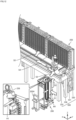
- FIG. 2 shows an outer appearance of the tool transfer system 10.
- the tool transfer system 10 includes a workstation 200, a tool storage section 250, a transfer device 300, and machine tools 400.
- the workstation 200 is a place where a worker performs work for tool holders.
- a tool holder is a pod capable of holding a tool. For example, the worker performs work to set tool holders or work to retrieve tool holders at the workstation 200.
- the workstation 200 includes an operation terminal 200A.
- the operation terminal 200A accepts various operations made to the tool transfer system 10.
- a plurality of tool holders may be stored in the tool storage section 250.
- the tool storage section 250 functions as a temporary storage place for the tool holders.
- the transfer device 300 transfers a designated tool holder among tool holders in the workstation 200, tool holders in the tool storage section 250, and tool holders in the machine tools 400, to a designated transfer destination, which is one of the workstation 200, the tool storage section 250, and the machine tools 400.
- a transfer mode in which the transfer device 300 carries a tool holder from the workstation 200 to the tool storage section 250 or any of the machine tools 400, or a transfer mode in which the transfer device 300 carries a tool holder from the tool storage section 250 to any of the machine tools 400 is also expressed as "to deliver”.
- a transfer mode in which the transfer device 300 carries a tool holder from the tool storage section 250 or any of the machine tools 400 to the workstation 200, or a transfer mode in which the transfer device 300 carries a tool holder from any of the machine tools 400 to the tool storage section 250 is also expressed as "to remove (move)".
- transfer device is a concept that encompasses various devices with a function of transferring tool holders.
- the following description takes a four- to seven-axis drive articulated robot as an example of the transfer device 300, but the transfer device 300 is not limited to an articulated robot.
- the transfer device 300 may alternatively be a two- or three-axis drive orthogonal robot (autoloader).
- the transfer device 300 may be a self-propelled robot.
- the transfer device 300 includes an arm robot 330, rails 331, and a shuttle 332.
- the arm robot 330 is fixed to the upper part of the shuttle 332.
- the shuttle 332 is movable on the rails 331.
- the tool storage section 250 and the machine tools 400 are arranged with the rails 331 therebetween and parallel with the rails 331.
- Each machine tool 400 is one of the transfer destinations, i.e. destinations to which the transfer device 300 transfers a tool holder.
- FIG. 2 shows six machine tools 400A to 400F as the machine tools 400, but the number of machine tools 400 in the tool transfer system 10 need only be at least one.
- Each machine tool 400 machines a workpiece in accordance with a pre-designed machining program, using a designated tool.
- the term "machine tool” as used herein is a concept that encompasses various devices with a function of machining a workpiece.
- the machine tool 400 may be a horizontal machining center or a vertical machining center.
- the machine tool 400 may be a lathe, an additive machine, or any other cutting or grinding machine.
- Search targets on the aforementioned search screen 130 include tools in the tool storage section 250, tools in the workstation 200, and tools in the machine tool 400. This allows the worker to search for tools that satisfy the search condition among the tools in the tool transfer system 10.
- the tool transfer system 10 may also include a pallet transfer system (not shown).
- a pallet transfer system is a system for transferring pallets each carrying a workpiece to the machine tools 400 in accordance with a predetermined machining schedule. With this, the tool transfer system 10 has not only an automatic tool transfer function but also an automatic workpiece transfer function.
- FIG. 3 shows a configuration example of drive mechanisms of the tool transfer system 10.
- the tool transfer system 10 includes a controller 50, a remote I/O (Input/Output) units 71 to 73, the workstation 200, the transfer device 300, and the machine tool 400.
- controller 50 means a device that controls the tool transfer system 10.
- the controller 50 may have any device configuration.
- the controller 50 may be constituted by a single control unit or a plurality of control units.
- the controller 50 includes a management device 100, a PLC 150, and the aforementioned operation terminal 200A.
- the controller 50 may also include a CNC (Computer Numerical Control) 401.
- the management device 100 is an example of the aforementioned information processing device 5.
- the management device 100 is a main computer that manages the tool transfer system 10.
- the management device 100 may be constituted by a single computer or a plurality of computers.
- the PLC 150 can communicate with various industrial devices for automating machining processes, and controls these industrial devices.
- the operation terminal 200A is an example of the aforementioned information processing device 5.
- the operation terminal 200A is a terminal for accepting various operations related to delivery and removal of tool holders.
- the management device 100, the PLC 150, and the operation terminal 200A are connected to a network NW1.
- the management device 100, the PLC 150, and the operation terminal 200A may be communicatively connected by wire or wirelessly.
- the network NW1 uses EtherNET (registered trademark) or the like.
- the management device 100 and the operation terminal 200A send a control command to the PLC 150 via the network NW1.
- the control command specifies a tool holder to be transferred, a transfer destination of the tool holder, start/stop of transfer of the tool holder, or the like.
- the remote I/O units 71 to 73 and the PLC 150 are connected to a network NW2.
- the network NW2 preferably is a field network that performs periodic communication and guarantees the arrival time of data.
- EtherCAT registered trademark
- EtherNet/IP registered trademark
- CC-Link registered trademark
- CompoNet registered trademark
- the workstation 200 includes at least one motor driver 234 and at least one motor 235.
- FIG. 3 shows an example of two motor drivers 234A and 234B and two motors 235A and 235B.
- the remote I/O unit 71 is installed in or around the workstation 200.
- the remote I/O unit 71 mediates data exchange between the PLC 150 and various drive units (e.g. motor drivers 234) in the workstation 200.
- various drive units e.g. motor drivers 234.
- each of the motor drivers 234 receives a control command from the PLC 150 via the remote I/O unit 71 at regular periods and controls driving of a corresponding motor 235 in accordance with the control command.
- the motor 235A controls driving of a later-described magazine M1 (see FIG. 12 ), which is located in the workstation 200.
- the motor 235B controls driving of an ATC (Automatic Train Control) in the workstation 200.
- ATC Automatic Train Control
- each motor driver 234 may be a driver for a servo motor or a driver for a stepping motor.
- Each motor 235 may be a servo motor or a stepping motor.
- the transfer device 300 includes at least one motor driver 334 and at least one motor 335.
- FIG. 3 shows an example of two motor drivers 334A and 334B and two motors 335A and 335B.
- the remote I/O unit 72 is installed in or around the transfer device 300.
- the remote I/O unit 72 mediates data exchange between the PLC 150 and various drive units (e.g. motor drivers 334) in the transfer device 300.
- various drive units e.g. motor drivers 334.
- each of the motor drivers 334 receives a control command from the PLC 150 via the remote I/O unit 72 at regular periods and controls driving of a corresponding motor 335 in accordance with the control command.
- the motor 335A controls driving of the aforementioned shuttle 332 (see FIG. 2 ).
- the motor 335B controls driving of the arm robot 330 (see FIG. 2 ).
- the number of motors 335B corresponds to the number of joints of the arm robot 330.
- each motor driver 334 may be a driver for a servo motor or a driver for a stepping motor.
- Each motor 335 may be a servo motor or a stepping motor.
- the machine tool 400 includes a CNC 401, at least one motor driver 411, and at least one motor 412.
- FIG. 3 shows an example of two motor drivers 411A and 411B and two motors 412A and 412B.
- the remote I/O unit 72 is installed in or around the machine tool 400.
- the remote I/O unit 72 mediates data exchange between the PLC 150 and various drive units (e.g. CNC 401) in the machine tool 400. Similar to the motor drivers 334, each of the motor drivers 411 receives a control command from the PLC 150 via the remote I/O unit 72 at regular periods and controls driving of a corresponding motor 412 in accordance with the control command.
- the motor 412A drives a main shaft, to which a tool can be attached, in an axial direction of the main shaft.
- the motor 412B drives the main shaft to rotate in a rotational direction about the axial direction of the main shaft.
- each motor driver 411 may be a driver for a servo motor or a driver for a stepping motor.
- Each motor 412 may be a servo motor or a stepping motor.
- FIG. 4 shows an example of functional constituents of the tool transfer system 10.
- the tool transfer system 10 includes, as functional constituents, a monitoring unit 52, a search unit 54, and a transfer control unit 56. These constituents are described in order below.
- the functional constituents may be arranged in any manner. Some or all of the functional constituents shown in FIG. 4 may be implemented in the aforementioned management device 100 (see FIG. 2 ), the aforementioned PLC 150 (see FIG. 2 ), the aforementioned operation terminal 200A (see FIG. 2 ), or the aforementioned CNC 401 (see FIG. 2 ).
- the monitoring unit 52 is implemented by, for example, the aforementioned PLC 150 or the aforementioned CNC 401.
- the monitoring unit 52 monitors a machining program 422 of the machine tool 400 and counts the amount of usage of each tool in the machine tool 400 from the new state to the present. Thereafter, the monitoring unit 52 updates the tool database 123 shown in FIG. 1 , based on the counted amount of usage.
- the machining program 422 for a workpiece includes a tool replacement command for designating a tool to be attached to the main shaft of the machine tool 400, a drive command for rotating or feeding the main shaft or the tool, or the like.
- the monitoring unit 52 stores the identification information regarding the tool when the tool replacement command specified in the machining program 422 is executed. Next, the monitoring unit 52 starts counting the amount of usage of the tool based on the drive command specified in the machining program 422 being executed. Next, the monitoring unit 52 stops counting the amount of usage of the tool based on a stop command specified in the machining program 422 or a command in the last line being executed. Next, the monitoring unit 52 references the tool database 123 and adds the counted amount of usage to the current amount of usage associated with the stored identification information. Thus, the monitoring unit 52 regularly updates the current amount of usage of each tool.
- the monitoring unit 52 when updating the current amount of usage of each tool specified in the tool database 123, the monitoring unit 52 also updates the remaining lifespan of each tool specified in the tool database 123. Typically, the monitoring unit 52 updates the remaining lifespan based on the result of subtracting the current amount of usage of the tool from the maximum usable amount of the tool.
- the search unit 54 is implemented by the aforementioned management device 100 or the aforementioned operation terminal 200A, for example.
- the search unit 54 searches the tool database 123 for tool information that satisfies an input search condition, and outputs the search results.
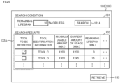
- FIG. 5 shows an example of a search screen 130.
- the search screen 130 includes an input area 131, a display field 132 for search results, and a retrieval button 133.
- the input area 131 accepts input of various search conditions. Input of a search condition to the input area 131 is realized by operating an input device, such as a mouse, or by touching the display 106, for example.
- the search unit 54 identifies tools that satisfy the input search condition among the tools specified in the tool database 123, based on a search execution button 131A in the input area 131 being pressed. Thereafter, the search unit 54 displays information regarding the identified tools in a display field 132 for the search results.
- the search results displayed in the display field 132 include, for example, identification information regarding the tools, the usable time of the tools, the current time of usage of the tools, and the remaining lifespan of the tools.
- the search screen 130 is capable of accepting a selection operation made to each piece of the tool information displayed as search results.
- the selection operation is made to a checkbox 132A.
- the status of the checkbox 132A switches between a selected state and a non-selected state each time the worker presses the checkbox 132A.
- the checkboxes 132A are provided according to the number of pieces of tool information displayed in the display field 132 for search results. Typically, the checkboxes 132A are arranged next to respective pieces of tool information displayed in the display field 132 for search results.
- the search unit 54 Based on the retrieval button 133 being pressed with a checkbox 132A selected, the search unit 54 outputs the selected piece of tool information to the transfer control unit 56.
- FIG. 6 shows an example of input to the transfer control unit 56 and output of the transfer control unit 56 in response to the input.
- the transfer control unit 56 is implemented by the aforementioned PLC 150, for example.
- the transfer control unit 56 receives a machining schedule 124 and storage information 175 as input, and outputs a command to transfer a tool holder to the transfer device 300.
- the machining schedule 124 specifies, for example, a scheduled machining timing for each workpiece in each of the machine tools 400, and tools used in each machining process.
- FIG. 6 shows an example of the machining schedule 124 for the machine tool 400A.
- the storage information 175 associates identification information regarding a tool holder stored at a storage location and identification information regarding a tool held by this tool holder with each other according to each of the storage locations where tool holders are stored in the tool transfer system 10.
- the storage locations specified in the storage information 175 are information for uniquely identifying the location of each tool holder in the tool transfer system 10.
- each storage location indicates any of the storage location of a tool holder in the workstation 200, the storage location of a tool holder in the tool storage section 250, the storage location of a tool holder in the transfer device 300, and the storage location of a tool holder in the machine tool 400.
- the identification information regarding each tool holder specified in the storage information 175 is information for uniquely identifying the tool holder.
- the identification information is assigned to each tool holder in advance.
- the identification information may be indicated by a tool holder number such as an ID, or a tool holder name.
- the identification information regarding each tool specified in the storage information 175 is information for uniquely identifying the tool.
- the identification information is assigned to each tool in advance.
- the identification information may be indicated by a tool number such as an ID, or a tool name. This identification information corresponds to the identification information regarding each tool specified in the aforementioned tool database 123 (see FIG. 1 ).
- the transfer control unit 56 references the machining schedule 124 and identifies the tool to be used, before the machine tool 400 starts machining a workpiece. Next, the transfer control unit 56 references the storage information 175, and if the tool to be used is not present in the target machine tool 400, the transfer control unit 56 causes the transfer device 300 to deliver the tool to be used from the workstation 200 or the tool storage section 250 to the target machine tool 400.
- the transfer control unit 56 controls the transfer device 300 so as to transfer, to the workstation 200, a tool corresponding to each piece of tool information selected in the display field 132 for search results.
- the location where the tool holder to be removed is stored is identified based on the storage information 175. More specifically, the transfer control unit 56 references the storage information 175 and identifies the storage location for each piece of tool information selected in the display field 132 for search results. The transfer control unit 56 then determines the tool holder holding the identified tool as a tool holder to be removed. As a result, tools that have reached the end of the lifespan thereof or tools that are about to reach the end of the lifespan thereof are removed from the tool storage section 250 or the machine tool 400 and moved to the workstation 200.
- FIG. 7 schematically shows a flow of search processing according to Variation 1.
- the tool database 123 shown in FIG. 1 described above associates the usable time of a tool, the current time of usage of the tool, and the remaining lifespan of the tool with each other according to identification information regarding each tool.
- a tool database 123A according to this variation also associates information regarding properties of the tool (hereinafter also referred to as "tool property information") according to identification information regarding each tool.
- the tool property information includes, for example, an indicator of the price of a tool, an indicator of the difficulty level of measurement work for the tool, an indicator of a skill required for handling the tool, and an indicator of the importance of the tool.
- the indicator of the value of a tool includes the price of the tool and classification such as high price or low price.
- the value of each tool may be set in advance or may be set in any manner by a user.
- the indicator of the difficulty level of measurement work for a tool includes a numerical value correlated with the difficulty level, a flag indicating whether or not the measurement work is difficult, and identification information regarding a measuring instrument necessary for the measurement work.
- the difficulty level of each tool may be set in advance, or may be set in any manner by a user.
- the indicator of a skill required for handling a tool includes a numerical value correlated with the difficulty level, and identification information regarding a worker authorized to handle the tool.
- the indicator of a skill for handling each tool may be set in advance, or may be set in any manner by a user.
- the importance of a tool includes a numerical value correlated with the importance and a flag indicating whether or not the tool is important.
- the importance of each tool of each tool may be set in advance, or may be set in any manner by a user.
- the search unit 54 accepts input of a search condition, and searches the tool database 123A for tool information that satisfies the input search condition.
- search conditions that can be input include the remaining lifespan proportion of a tool.
- the search unit 54 searches the tool database 123A for tool information indicating a remaining lifespan proportion less than or equal to the input remaining lifespan proportion.
- the search results are displayed in the display field 132 of the search screen 130A.
- identification information regarding tools, the usable time of the tools, the current time of usage of the tools, the remaining lifespan of the tools, and property information regarding the tools are displayed as search results on the search screen 130A.
- search conditions that can be input include tool property information.
- the search unit 54 searches the tool database 123A for tool information whose price is higher than or equal to the lower limit value.
- the search results are displayed in the display field 132 of the search screen 130A.
- the search condition may be designated by a combination of the remaining lifespan proportion of a tool and tool property information.
- FIG. 8 schematically shows a flow of search processing according to Variation 2.
- the tool database 123 shown in FIG. 1 associates the usable time of a tool, the current time of usage of the tool, and the remaining lifespan of the tool with each other according to identification information regarding each tool.
- the tool database 123B according to this variation also associates a tool classification according to the identification information regarding each tool.
- Tool classifications and tools pertaining to each classification are specified in advance.
- the tool classification includes, for example, a cutter, a reamer, and another classification name.
- the search unit 54 accepts input of a search condition, and searches the tool database 123B for tool information that satisfies this search condition.
- search conditions that can be input include the remaining lifespan proportion of a tool.
- the search unit 54 searches the tool database 123B for tool information indicating a remaining lifespan proportion less than or equal to the input remaining lifespan proportion.
- the search results are displayed in a display field 132 of a search screen 130B.
- classifications of tools, identification information regarding the tools, the usable time of the tools, the current time of usage of the tools, the remaining lifespan of the tools, and the property information regarding the tools are displayed on the search screen 130B.
- search conditions that can be input include a tool classification.
- a tool classification is input as a search condition
- the search unit 54 searches the tool database 123B for tool information that matches the input classification, and displays the tool information on the search screen 130B.
- the search condition may be designated by a combination of the remaining lifespan proportion of a tool and a tool classification.
- FIG. 9 schematically shows a flow of search processing according to Variation 3.
- the search screen 130 shown in FIG. 1 displays identification information regarding tools, the usable time of the tools, the current time of usage of the tools, and the remaining lifespan of the tools as search results.
- a search screen 130C according to this variation also displays storage locations of the tools as search results.
- the search unit 54 acquires tool information that matches the input search condition from the tool database 123.
- the search unit 54 searches the storage information 175 for the storage location of each tool using the identification information regarding the tools specified in the tool information as a key. Subsequently, the search unit 54 displays information regarding the tools that match the search condition and the storage locations of the tools side by side on the search screen 130C.
- FIG. 10 shows a left part of the search screen 130.
- FIG. 11 shows a right part of the search screen 130.
- the search screen 130 includes the input area 131 for search conditions and a display field 132 for search results.
- the input area 131 for search conditions is constituted by input fields 135A to 135F.
- the input field 135A accepts input of a tool classification as a search condition.
- the tool classification is input in the form of a group number, for example.
- the input field 135B accepts input of a transfer status of a tool as a search condition.
- the transfer statuses that can be input include, for example, "Finished” indicating that transfer of the tool is complete, “Ongoing” indicating that the tool is currently being transferred, “Not yet” indicating that transfer of the tool is not yet complete, and “Unnecessary” indicating that the tool need not be transferred.
- the input field 135C accepts input of a tool storage location in or out of the tool storage section 250 as a search condition.
- the tool storage locations that can be input include "In CTS” indicating that the tool is stored in the tool storage section 250, "Floor” indicating a different location other than the tool transfer system 10, "No Data” indicating that data of the storage location of the tool is not registered, and "None” indicating that the storage location of the tool is unknown.
- the input field 135D accepts input of a tool storage location in or out of the machine tools 400 as a search condition.
- the tool storage locations that can be input include “All” indicating all of the machine tools 400, and "MC_01”, “MC_02”, and “MC_03” indicating identification information regarding specific machine tools 400.
- the input field 135E accepts input of the date and time range of the scheduled machining time.
- the date and time range is designated by either the start date and time or the end date and time.
- the input field 135F accepts input of a remaining lifespan condition.
- the remaining lifespan condition is input in the form of a combination of a numerical value and a unit, for example.
- the unit may be "% or less", “% or more”, “minutes or less", “minutes or more”, or the like.
- the search unit 54 recognizes that a search condition that the remaining lifespan proportion is "10% or less” has been designated.
- the search unit 54 recognizes that a search condition that the remaining lifespan proportion is "10 minutes or less” has been designated.
- the search unit 54 searches the tool database 123 for tool information that matches the search condition input in the input area 131, and outputs the search results in the display field 132.
- the display field 132 for search results includes a display field 141 related to machining schedules, and a display field 142 related to tool information.
- the display field 141 includes a sequence number 141A indicating the execution order of machining tasks, date information 141B indicating a machining date, machining start information 141C indicating a machining start time, identification information 141D regarding a machine tool that performs machining, classification 141E of a tool used in machining, and machining time information 141F indicating a time required for machining.
- the display field 142 includes amount-of-usage information 142A indicating the amount by which a tool has been used in machining since the new state to the present, storage location information 142B indicating the storage location of the tool, identification information 142C regarding the tool, remaining lifespan information 142D indicating the remaining lifespan of the tool, and 142E indicating the transfer status of the tool.
- amount-of-usage information 142A indicating the amount by which a tool has been used in machining since the new state to the present
- storage location information 142B indicating the storage location of the tool
- identification information 142C regarding the tool identification information 142C regarding the tool
- remaining lifespan information 142D indicating the remaining lifespan of the tool
- 142E indicating the transfer status of the tool.
- FIG. 12 schematically shows a flow of a process of delivering a tool holder from the workstation 200 to the tool storage section 250.
- step S1 the worker sets a tool holder H1 to be delivered to a magazine M1 in the workstation 200.
- the number of tool holders that can be stored in the workstation 200 is smaller than the number of tool holders that can be stored in the tool storage section 250.
- a reader device (not shown) for reading a bar code or a QR code (registered trademark) is provided near the location where the worker sets the tool holder H1 to the magazine M1.
- the reader device reads a bar code or a QR code attached to the tool holder H1. Identification information regarding the tool holder H1 to be delivered is thus read.
- the worker After completing the setting of the tool holder H1, the worker performs a completion operation to the operation terminal 200A.
- step S2 the controller 50 controls the motor 235A (see FIG. 3 ) and drives the magazine M1 in the workstation 200.
- the controller 50 thus moves the tool holder H1 to be delivered to a predetermined tool replacement position.
- the ATC 238 is provided near the tool replacement position.
- the ATC 238 detaches the tool holder H1 at the tool replacement position from the magazine M1 and makes a half turn.
- step S3 the arm robot 330 detaches the tool holder H1 from the ATC 238 and places the tool holder H1 in a temporary storage place 336 on the shuttle 332. If there is another tool holder to be delivered, the process in steps S1 to S3 is repeated as long as the maximum storable number of the temporary storage place 336 is not exceeded.
- step S4 the controller 50 controls the motor 335Ato drive the shuttle 332.
- the controller 50 thus moves the shuttle 332 to an instructed tool delivery position.
- the tool delivery position is determined based on the aforementioned storage information 175 (see FIG. 6 ), for example.
- the controller 50 references a vacant storage location specified in the storage information 175 and determines the storage destination of the tool holder H1. If there are a plurality of vacant storage locations, the controller 50 may determine, as the storage destination, one storage location randomly selected from among the plurality of vacant storage locations, or determine, as the storage destination, one storage location that is closer to the transfer device 300 and selected from among the plurality of vacant storage locations.
- step S5 the arm robot 330 detaches the tool holder H1 to be delivered from the temporary storage place 336 and stores the tool holder H1 in the determined storage destination. Thereafter, the controller 50 updates the storage information 175 by associating the identification information regarding the tool holder H1 with the corresponding storage location.
- controller 50 repeats the process in steps S4 and S5 until no tool holder is left on the temporary storage place 336.
- FIG. 13 schematically shows a flow of a process of delivering a tool holder from the tool storage section 250 to the machine tool 400.
- the controller 50 receives an instruction to deliver a tool holder to the machine tool 400.
- the worker designates, on the operation terminal 200A, the tool to be delivered and the machine tool 400 that is the transfer destination. If there are more than one tool holder holding the tool designated by the worker in the tool storage section 250, the controller 50 identifies a tool holder to be delivered. It is assumed that a tool holder H2 is thus identified as a tool to be delivered. In this case, the controller 50 identifies the storage location of the tool holder H2 from the aforementioned storage information 175 (see FIG. 6 ). Thereafter, the controller 50 drives the shuttle 332 by controlling the motor 335A(see FIG. 3 ), and moves the shuttle 332 to the front of the storage location of the tool holder H2.
- step S11 the arm robot 330 takes out the tool holder H2 to be delivered from the tool storage section 250 and places the tool holder H2 in the temporary storage place 336 on the shuttle 332.
- step S12 the controller 50 drives the shuttle 332 to the position of the machine tool 400 that is the delivery destination by controlling the motor 335A.
- step S13 the arm robot 330 passes the tool holder H2 to the ATC 438 provided in the machine tool 400 that is the transfer destination. Thereafter, the ATC 438 attaches the tool holder H2 received from the arm robot 330 to the ATC 438 in the machine tool 400. Thereafter, the ATC 438 sets the tool holder H2 to a magazine in the machine tool 400. The tool holder H2 thus becomes available in the machine tool 400.
- FIG. 14 schematically shows a flow of a process of removing a tool holder from the machine tool 400 and moving the removed tool holder to the workstation 200.
- the controller 50 receives an instruction to retrieve a tool holder. Based on this, the controller 50 identifies a tool holder to be retrieved from among tool holders stored in the tool storage section 250 or the machine tool 400. It is assumed that, as a result, a tool holder H3 is identified as the tool holder to be retrieved.
- the controller 50 references the aforementioned storage information 175 (see FIG. 6 ) and identifies a storage destination of the tool holder H3. Thereafter, the controller 50 drives the shuttle 332 by controlling the aforementioned motor 335A (see FIG. 3 ) and moves the shuttle 332 to the storage destination of the tool holder H3.
- the arm robot 330 takes out the tool holder H3 from the storage destination and places the tool holder H3 in the temporary storage place 336 on the shuttle 332. Further, the controller 50 deletes identification information regarding the tool holder H3 from the storage information 175 and makes empty an entry corresponding to the storage location of the tool holder H3.
- step S21 the controller 50 drives the shuttle 332 by controlling the aforementioned motor 335A, and moves the shuttle 332 from the storage destination of the tool holder H3 to the front of the workstation 200.
- step S22 the arm robot 330 detaches each tool holder H3 to be removed from the temporary storage place 336 and attaches the tool holder H3 to the aforementioned ATC 238 (see FIG. 12 ) in the workstation 200. Thereafter, the ATC 238 attaches the tool holder H3 to the magazine M1 of the workstation 200.
- step S23 the controller 50 drives the magazine M1 by controlling the aforementioned motor 235A, and moves the tool holder H3 to be removed to an exit. Thereafter, the worker takes out the tool holder H3 to be removed from the exit.
- FIG. 15 is a schematic diagram showing an example of a hardware configuration of the management device 100.
- the management device 100 includes a control circuit 101, a ROM (Read Only Memory) 102, a RAM (Random Access Memory) 103, a communication interface 104, a display interface 105, an input interface 107, and a storage device 120. These components are connected to a bus 110.
- ROM Read Only Memory
- RAM Random Access Memory
- the control circuit 101 is constituted by at least one integrated circuit, for example.
- the integrated circuit may be constituted by, for example, at least one CPU (Central Processing Unit), at least one GPU (Graphics Processing Unit), at least one ASIC (Application Specific Integrated Circuit), at least one FPGA (Field Programmable Gate Array), or a combination thereof.
- CPU Central Processing Unit
- GPU Graphics Processing Unit
- ASIC Application Specific Integrated Circuit
- FPGA Field Programmable Gate Array
- the control circuit 101 controls operation of the management device 100 by executing a search program 122 and various programs, such as an operating system.
- the control circuit 101 loads the search program 122 from the storage device 120 or the ROM 102 to the RAM 103 in response to receiving a command to execute the search program 122.
- the RAM 103 functions as a working memory and temporarily stores various data necessary for executing the search program 122.
- a LAN Local Area Network
- an antenna or the like is connected to the communication interface 104.
- the management device 100 is connected to the network NW1 via the communication interface 104. With this, the management device 100 exchanges data with external devices connected to the network NW1.
- the external device includes, for example, the PLC 150, a server (not shown), or the like.
- a display 106 is connected to the display interface 105.
- the display interface 105 sends an image signal for displaying an image to the display 106 in accordance with an instruction from the control circuit 101 or the like.
- the display 106 displays, for example, an operation screen for accepting an instruction to retrieve a tool holder, a selection screen for designating a tool holder to be delivered, or the like.
- the display 106 is, for example, a liquid crystal display, an organic EL (Electro Luminescence) display, or other display equipment. Note that the display 106 may be integrated with the management device 100, or may be separate from the management device 100.
- An input device 108 is connected to the input interface 107.
- the input device 108 is, for example, a mouse, a keyboard, a touch panel, or other device capable of accepting user operations. Note that the input device 108 may be integrated with the management device 100, or may be separate from the management device 100.
- the storage device 120 is, for example, a storage medium such as a hard disk or a flash memory.
- the storage device 120 stores the search program 122, the aforementioned tool database 123, the aforementioned machining schedule 124, or the like.
- the storage locations thereof are not limited to the storage device 120, and may alternatively be stored in a storage area (e.g. cache memory etc.) of the control circuit 101, the ROM 102, the RAM 103, or any other device (e.g. server, PLC 150, or operation terminal 200A).
- the search program 122 is a program for realizing the aforementioned search function.
- the search program 122 may be provided not as a standalone program but as a part of any program. In this case, transfer control processing based on the search program 122 is realized in cooperation with that program. Even if a program that does not include such a part of a module is used, it does not deviate from the gist of the search program 122 according to this embodiment.
- some or all of the functions provided by the search program 122 may be realized by dedicated hardware.
- the management device 100 may be configured in a form such as a so-called cloud service in which at least one server executes a part of processing of the search program 122.
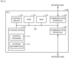
- FIG. 16 is a block diagram showing a main hardware configuration of the PLC 150.
- the PLC 150 includes a control circuit 151, a ROM (Read Only Memory) 152, a RAM (Random Access Memory) 153, communication interfaces 154 and 155, and a storage device 170. These components are connected to a bus 160.
- ROM Read Only Memory
- RAM Random Access Memory
- the control circuit 151 is constituted by at least one integrated circuit.
- the integrated circuit may be constituted by, for example, at least one CPU, at least one MPU (Micro Processing Unit), at least one ASIC (application), at least one FPGA, or a combination thereof.
- the control circuit 151 controls operations of the transfer device 300 and the machine tool 400 by executing a control program 172 and various programs.
- the control circuit 151 loads the control program 172 from the storage device 170 to the ROM 152 in response to receiving a command to execute the control program 172.
- the RAM 153 functions as a working memory and temporarily stores various data necessary for executing the control program 172.
- a LAN, an antenna, or the like is connected to the communication interface 154.
- the PLC 150 is connected to the network NW1 via the communication interface 154. With this, the PLC 150 exchanges data with an external device connected to the network NW1.
- the external device includes, for example, the management device 100, a server (not shown), or the like.
- the communication unit 155 is a communication interface for connection to the network NW2.
- the PLC 150 exchanges data with the external device connected to the network NW2 via the communication interface 155.
- the external device includes, for example, any of the aforementioned remote I/O units 71 to 73.
- the storage device 170 is, for example, a storage medium such as a hard disk or a flash memory.
- the storage device 170 stores the control program 172, the aforementioned storage information 175, or the like.
- the storage location of the control program 172, the tool information 174, and the storage information 175 is not limited to the storage device 170, and may alternatively be stored in a storage area (e.g. cache memory etc.) of the control circuit 151, the ROM 152, the RAM 153, or any other device (e.g. server).
- FIG. 17 is a schematic diagram showing an example of a hardware configuration of the operation terminal 200A.
- the operation terminal 200A includes a control circuit 201, a ROM 202, a RAM 203, a communication interface 204, a display interface 205, an input interface 207, and a storage device 220. These components are connected to a bus 210.
- the control circuit 201 is constituted by at least one integrated circuit, for example.
- the integrated circuit may be constituted by, for example, at least one CPU, at least one GPU, at least one ASIC, at least one FPGA, or a combination thereof.
- the control circuit 201 controls operations of the operation terminal 200A by executing a search program 222 and various programs such as an operating system.
- the control circuit 201 loads the search program 222 from the storage device 220 or the ROM 202 to the RAM 203 in response to receiving a command to execute the search program 222.
- the RAM 203 functions as a working memory and temporarily stores various data necessary for executing the search program 222.
- a LAN, an antenna, or the like is connected to the communication interface 204.
- the operation terminal 200A is connected to the network NW1 via the communication interface 204. With this, the operation terminal 200A exchanges data with an external device connected to the network NW1.
- the external device includes, for example, the PLC 150, a server (not shown), or the like.
- a display 206 is connected to the display interface 205.
- the display interface 205 sends an image signal for displaying an image to the display 206 in accordance with an instruction from the control circuit 201 or the like.
- the display 206 displays, for example, an operation screen for accepting an instruction to retrieve a tool holder, a tool selection screen for designating a tool holder to be delivered, a machine tool selection screen for designating a machine tool 400 that is a delivery destination, or the like.
- the display 206 is, for example, a liquid crystal display, an organic EL display, or other display equipment. Note that the display 206 may be integrated with or separate from the operation terminal 200A.
- An input device 208 is connected to the input interface 207.
- the input device 208 is, for example, a mouse, a keyboard, a touchscreen, or other device capable of accepting user operations. Note that the input device 208 may be integrated with or separate from the operation terminal 200A.
- the storage device 220 is, for example, a storage medium such as a hard disk or a flash memory.
- the storage device 220 stores the search program 222 or the like.
- the storage location of the search program 222 is not limited to the storage device 220, and may alternatively be stored in a storage area (e.g. cache memory etc.) of the control circuit 201, the ROM 202, the RAM 203, the management device 100, the PLC 150, an external device (e.g. server), or the like.
- the search program 222 is a program for realizing the aforementioned search function.
- the search program 222 may be provided not as a standalone program but as a part of any program. In this case, transfer control processing based on the search program 222 is realized in cooperation with that program. Even if a program that does not include such a part of a module is used, it does not deviate from the gist of the search program 222 according to this embodiment. Furthermore, some or all of the functions provided by the search program 222 may be realized by dedicated hardware.
- the operation terminal 200A may be configured in a form such as a so-called cloud service in which at least one server executes a part of processing of the search program 222.
- FIG. 18 is a flowchart showing a flow of tool information search processing.
- the search processing shown in FIG. 18 is performed by the control circuit 101 of the management device 100 executing the aforementioned search program 122.
- the search processing shown in FIG. 18 may be realized by the control circuit 201 of the operation terminal 200A executing the aforementioned search program 222.
- a part or the entirety of the processing may be executed by a circuit element or other hardware.
- step S110 the control circuit 101 determines whether or not the control circuit 101 has accepted an operation to display the aforementioned search screen 130. As an example, the control circuit 101 determines that the control circuit 101 has accepted an operation to display the search screen 130 based on the search program 122 being executed. If the control circuit 101 determines that the control circuit 101 has accepted an operation to display the search screen 130 (YES in step S110), the control circuit 101 switches control to step S 112. If not (NO in step S110), the control circuit 101 executes processing in step S110 again.
- step S112 the control circuit 101 causes the display 106 to display the search screen 130 for tool information.
- the search screen 130 enables input of search conditions for tool information. Search conditions that can be input include, for example, a search condition related to the remaining lifespan of a tool.
- step S120 the control circuit 101 determines whether or not the control circuit 101 has accepted a search execution operation performed on the search screen 130.
- a search execution operation is performed by pressing a search execution button 131A in the search screen 130. If the control circuit 101 determines that the control circuit 101 has accepted a search execution operation performed on the search screen 130 (YES in step S120), the control circuit 101 switches control to step S124. If not (NO in step S120), the control circuit 101 switches control to step S122.
- step S122 the control circuit 101 determines whether or not the control circuit 101 has accepted a cancel operation performed on the search screen 130. As an example, a cancel operation is performed by closing the search screen 130. If the control circuit 101 determines that the control circuit 101 has accepted a cancel operation performed on the search screen 130 (YES in step S122), the control circuit 101 ends the search processing shown in FIG. 18 . If not (NO in step S122), the control circuit 101 returns control to step S120.
- step S124 the control circuit 101 functions as the aforementioned search unit 54 and acquires tool information that satisfies the input search condition from the aforementioned tool database 123.
- the input search condition is an upper limit of the remaining lifespan proportion
- the control circuit 101 references tool information specified in the tool database 123 and acquires the maximum usable amount and the remaining lifespan of each tool.
- the control circuit 101 calculates the proportion of the remaining lifespan to the maximum usable amount for each tool, and searches tool information with a remaining lifespan proportion that is lower than or equal to the upper limit.
- step S126 the control circuit 101 functions as the aforementioned search unit 54 and displays the results of the search processing in step S124 in the display field 132 of the search screen 130.
- the search screen 130 is capable of accepting a selection operation to select each piece of tool information displayed in the display field 132.
- the tool corresponding to the selected piece of tool information is recognized as a tool to be retrieved.
- step S130 the control circuit 101 determines whether or not the control circuit 101 has accepted a tool retrieval operation performed on the search screen 130.
- a tool retrieval operation is performed by pressing the retrieval button 133 in the search screen 130. If the control circuit 101 determines that the control circuit 101 has accepted a tool retrieval operation performed on the search screen 130 (YES in step S130), the control circuit 101 switches control to step S134. If not (NO in step S130), the control circuit 101 switches control to step S132.
- step S132 the control circuit 101 determines whether or not the control circuit 101 has accepted a cancel operation performed on the search screen 130. As an example, a cancel operation is performed by closing the search screen 130. If the control circuit 101 determines that the control circuit 101 has accepted a cancel operation performed on the search screen 130 (YES in step S132), the control circuit 101 ends the search processing shown in FIG. 18 . If not (NO in step S132), the control circuit 101 returns control to step S130.
- step S134 the control circuit 101 outputs, to the transfer device 300, a transfer command to cause the transfer device 300 to move each tool corresponding to the pieces of tool information selected in the search result display field to the workstation 200.
- the machining system 1 accepts input of a search condition related to the remaining lifespan of a tool on the search screen 130 for tool information.
- the machining system 1 identifies tools whose remaining lifespan satisfies the search condition among the tools specified in the tool database 123, based on the current amount of usage of each tool. Thereafter, the search screen 130 displays information regarding the identified tools as the search results.
- the worker can search for tool information with the search condition related to the remaining lifespan by using the search function of the machining system 1. This allows the worker to understand not only tools that have reached the end of the lifespan thereof but also tools that are about to reach the end of the lifespan thereof. As a result, the worker can identify tools that are better to be replaced now.
Landscapes
- Engineering & Computer Science (AREA)
- Mechanical Engineering (AREA)
- Physics & Mathematics (AREA)
- Theoretical Computer Science (AREA)
- General Physics & Mathematics (AREA)
- Manufacturing & Machinery (AREA)
- Data Mining & Analysis (AREA)
- General Engineering & Computer Science (AREA)
- Databases & Information Systems (AREA)
- Computational Linguistics (AREA)
- Geometry (AREA)
- Human Computer Interaction (AREA)
- Automation & Control Theory (AREA)
- General Factory Administration (AREA)
- Numerical Control (AREA)
Abstract
Description
- The present disclosure relates to a technology for searching tool information.
- The larger the number of machine tools to manage is, the more difficult it is to manage tools used in each machine tool. In this respect, Patent Document 1 (International Publication No.
2015/029232 ) discloses a tool management system. A tool database is stored in this tool management system. Tool data specifies the length, diameter, or the like of each tool. - Patent Document 1: International Publication No.
2015/029232 - Each tool has a limited lifespan. It is recommended to replace a tool that has reached the end of the lifespan thereof with a new tool. The larger the number of tools used is, the more difficult tool replacement work is. Therefore, tool replacement work is performed altogether during a hiatus or the like. Here, for the efficiency of tool replacement work, it is favorable to perform replacement work not only for tools that have reached the end of the lifespan, but also for tools that are about to reach the end of the lifespan thereof.
- To assist in such tool replacement work, there is demand for a technology for searching tool information using search conditions regarding the remaining lifespan of the tools. Note that
Patent Document 1 mentioned above does not disclose anything regarding this type of technology. - In an example of the present disclosure, a machining system in which a plurality of tools are used to machine a workpiece includes a display unit capable of displaying a search screen for searching for a tool. The search screen is capable of accepting input of a search condition related to a remaining lifespan of a tool. The machining system also includes a search unit for searching for a tool whose remaining lifespan or amount of usage satisfies the search condition, among the plurality of tools, based on an amount of usage of each of the tools from a new state. The search screen displays, as a search result, information regarding a tool that satisfies the search condition.
- In an example of the present disclosure, the machining system includes: a machine tool; a tool storage section in which a plurality of tools are able to be stored; a workstation for a worker to perform work for a tool; and a transfer device for transferring a designated tool among a tool in the machine tool, a tool in the tool storage section, and a tool in the workstation, to a designated delivery destination, which is one of the machine tool, the tool storage section, and the workstation. Search targets on the search screen include a tool in the machine tool, a tool in the tool storage section, and a tool in the workstation.
- In an example of the present disclosure, the search screen is capable of accepting a selection operation to select a piece of information regarding each tool displayed as the search result. The machining system further includes a transfer control unit for controlling the transfer device so as to transfer a tool corresponding to the piece of information selected by the selection operation to the workstation.
- In an example of the present disclosure, information regarding each tool displayed as the search result on the search screen includes identification information regarding the tool, and a remaining lifespan of the tool or an amount of usage of the tool.
- In an example of the present disclosure, the information regarding each tool displayed as the search result on the search screen further includes information regarding a property of the tool.
- In an example of the present disclosure, the information regarding each tool displayed as the search result on the search screen further includes a classification of the tool.
- In an example of the present disclosure, the search unit searches for a tool whose remaining lifespan satisfies the search condition among the plurality of tools. The search condition able to be input on the search screen includes at least one of a proportion of a remaining lifespan of a tool to a lifespan of the tool from a new state and a proportion of an amount of usage of the tool to the lifespan of the tool from the new state.
- In another example of the present disclosure, a search method for searching for a specific tool among a plurality of tools to be used in a machining system is provided. The search method includes: a step of displaying a search screen for searching for a tool; a step of accepting input of a search condition related to a remaining lifespan of a tool on the search screen; a step of searching for a tool whose remaining lifespan or amount of usage satisfies the search condition, among the plurality of tools, based on an amount of usage of each of the tools from a new state; and a step of displaying information regarding a tool that satisfies the search condition as a search result on the search screen.
- In another example of the present disclosure, a search program for searching for a specific tool among a plurality of tools to be used in a machining system is provided. The search program causes a computer to execute: a step of displaying a search screen for searching for a tool; a step of accepting input of a search condition related to a remaining lifespan of a tool on the search screen; a step of searching for a tool whose remaining lifespan or amount of usage satisfies the search condition, among the plurality of tools, based on an amount of usage of each of the tools from a new state; and a step of displaying information regarding a tool that satisfies the search condition as a search result on the search screen.
- The above and other objects, features, aspects and advantages of the present invention will become apparent from the following detailed description of the invention as understood in connection with the accompanying drawings.
-
-
FIG. 1 schematically shows a flow of tool information search processing. -
FIG. 2 shows an outer appearance of a tool transfer system. -
FIG. 3 shows a configuration example of drive mechanisms of the tool transfer system. -
FIG. 4 shows an example of functional constituents of the tool transfer system. -
FIG. 5 shows an example of a search screen. -
FIG. 6 shows an example of input to a transfer control unit and output of the transfer control unit in response to the input. -
FIG. 7 schematically shows a flow of search processing according toVariation 1. -
FIG. 8 schematically shows a flow of search processing according toVariation 2. -
FIG. 9 schematically shows a flow of search processing according toVariation 3. -
FIG. 10 shows a left part of the search screen. -
FIG. 11 shows a right part of the search screen. -
FIG. 12 schematically shows a flow of a process of delivering a tool holder from a work station to a tool storage section. -
FIG. 13 schematically shows a flow of a process of delivering a tool holder from the tool storage section to a machine tool. -
FIG. 14 schematically shows an example of a mode of removing a tool holder from the machine tool and moving the removed tool holder to the tool holder. -
FIG. 15 is a schematic diagram showing an example of a hardware configuration of a management device. -
FIG. 16 is a block diagram showing a main hardware configuration of a PLC (Programmable Logic Controller). -
FIG. 17 is a schematic diagram showing an example of a hardware configuration of an operation terminal. -
FIG. 18 is a flowchart showing a flow of tool information search processing. - Hereinafter, embodiments according to the present invention will be described with reference to the drawings. In the following description, identical components and constituent elements are given identical reference signs. Those components and constituent elements also have the same names and functions. Accordingly, detailed descriptions thereof are not repeated. Note that the following embodiments and variations may be selectively combined as appropriate.
- An overview of a tool search function is described with reference to
FIG. 1. FIG. 1 schematically shows a flow of tool information search processing. - A
machining system 1 is shown inFIG. 1 . Themachining system 1 is a system capable of machining a workpiece using a plurality of tools. Themachining system 1 includes aninformation processing device 5 and a display 106 (display unit). - The
information processing device 5 is a device for managing the tools used in themachining system 1. Theinformation processing device 5 may be constituted by a single computer or a plurality of computers. The computer may be a desktop PC (Personal Computer), a laptop PC, or a mobile terminal. As an example, theinformation processing device 5 is a later-described management device 100 (seeFIG. 3 ) or a later-describedoperation terminal 200A (seeFIG. 3 ). - The
display 106 is, for example, a liquid-crystal display, an organic EL (Electro Luminescence) display, or other display equipment. Thedisplay 106 may be integrated with or separate from theinformation processing device 5. - A
tool database 123 is stored in theinformation processing device 5. Various types of information regarding the tools are specified in thetool database 123. As an example, in thetool database 123, the maximum usable time of a tool, the current amount of usage of the tool, and the remaining lifespan of the tool are associated with each other according to identification information regarding each tool. - The identification information regarding each tool specified in the
tool database 123 is information for uniquely identifying the tool. The identification information is assigned to each tool in advance. As an example, the identification information may be indicated by a tool number such as an ID (Identification), or a tool name. - The maximum usable amount specified in the
tool database 123 is an indicator of the amount of usage of the tool from the new state until the tool reaches the end of the lifespan thereof. The term "maximum usable amount of a tool" includes, for example, the time that the tool can be used for machining from the new state until the tool reaches the end of the lifespan thereof, the distance that the tool can move during machining from the new state until the tool reaches the end of the lifespan thereof, and the number of times that the tool can be used from the new state until the tool reaches the end of the lifespan thereof. - The current amount of usage specified in the
tool database 123 is an indicator of the amount of usage of the tool from the new state to the present. The term "amount of usage of a tool" includes, for example, the total time that the tool has been used for machining since the new state to the present, the total distance that the tool has moved during machining since the new state to the present, and the total number of times that the tool has been used since the new state to the present. - The remaining lifespan specified in the
tool database 123 is an indicator of the amount of usage of the tool from the present until the tool reaches the end of the lifespan thereof. The term "remaining lifespan of a tool" includes, for example, the time that the tool can be used for machining from the present until the tool reaches the end of the lifespan thereof, the distance that the tool can move during machining from the present until the tool reaches the end of the lifespan thereof, and the number of times that the tool can be used from the present until the tool reaches the end of the lifespan thereof. - The
information processing device 5 has a function of searching tool information. The search function is realized by asearch screen 130 for searching tool information, for example. Thesearch screen 130 is displayed on thedisplay 106, for example. - The
search screen 130 accepts input of various search conditions. A search condition may be input to aninput area 131 of thesearch screen 130. Input of the search condition to theinput area 131 is realized by operating an input device, such as a mouse, or by touching thedisplay 106, for example. - The
search screen 130 accepts input of a search condition related to the remaining lifespan of tools. In the example inFIG. 1 , thesearch screen 130 accepts the proportion of the remaining lifespan of a tool to the maximum usable amount of the tool (hereinafter also referred to as "remaining lifespan proportion") as a search condition. - The
information processing device 5 identifies tools whose remaining lifespan satisfies the search condition among the tools specified in thetool database 123, based on the current amount of usage of each tool used in themachining system 1. Thereafter, thesearch screen 130 displays information regarding the identified tools in adisplay field 132 for search results. - In the example in
FIG. 1 , a remaining lifespan proportion of "10% or less" is input as a search condition. In this case, theinformation processing device 5 identifies tool information including a remaining lifespan proportion of "10% or less" from thetool database 123. In the example inFIG. 1 , the remaining lifespan proportion of a tool A is 90% (= 900 / 1000), the remaining lifespan proportion of a tool B is approximately 67% (= 1000 / 1500), the remaining lifespan proportion of a tool C is 0% (= 0 / 1200), and the remaining lifespan proportion of a tool D is 1.1% (= 15 / 1300). Therefore, thesearch screen 130 displays information regarding the tool C and the tool D in thedisplay field 132. - Thus, the worker can search tool information with a search condition related to the remaining lifespan by means of the search function of the
machining system 1. This allows the worker to understand not only tools that have reached the end of the lifespan thereof but also tools that are about to reach the end of the lifespan thereof. As a result, the worker can identify tools that are better to be replaced now. - The search function may be used during a hiatus of the worker, for example. The hiatus includes a time period before the worker switches with the next worker, and a time period before a holiday such as a Saturday or a Sunday. The worker can efficiently perform tool replacement work by replacing not only tools that have reached the end of the lifespan thereof but also tools that are about to reach the end of the lifespan thereof, during a hiatus.
- Note that the search condition that can be input is not limited to the remaining lifespan proportion. As an example, search conditions that can be input include the proportion of the amount of usage of each tool to the maximum usable amount of the tool (hereinafter also referred to as "usage amount proportion"). In this case, the
information processing device 5 specifies a tool with an amount of usage that satisfies the search condition from among the tools specified in thetool database 123. - Next, a
tool transfer system 10, which is an example of theaforementioned machining system 1, is described with reference toFIG. 2 . - The following is a description of the
tool transfer system 10 as an example of themachining system 1, but themachining system 1 is not limited to thetool transfer system 10. Themachining system 1 need not necessarily have an automatic tool transfer function. As an example, themachining system 1 may be constituted by the aforementionedinformation processing device 5 and a plurality of machine tools. -
FIG. 2 shows an outer appearance of thetool transfer system 10. As shown inFIG. 2 , thetool transfer system 10 includes aworkstation 200, atool storage section 250, atransfer device 300, andmachine tools 400. - The
workstation 200 is a place where a worker performs work for tool holders. A tool holder is a pod capable of holding a tool. For example, the worker performs work to set tool holders or work to retrieve tool holders at theworkstation 200. - The
workstation 200 includes anoperation terminal 200A. Theoperation terminal 200A accepts various operations made to thetool transfer system 10. - A plurality of tool holders may be stored in the
tool storage section 250. Thetool storage section 250 functions as a temporary storage place for the tool holders. - The
transfer device 300 transfers a designated tool holder among tool holders in theworkstation 200, tool holders in thetool storage section 250, and tool holders in themachine tools 400, to a designated transfer destination, which is one of theworkstation 200, thetool storage section 250, and themachine tools 400. - In the following, a transfer mode in which the
transfer device 300 carries a tool holder from theworkstation 200 to thetool storage section 250 or any of themachine tools 400, or a transfer mode in which thetransfer device 300 carries a tool holder from thetool storage section 250 to any of themachine tools 400 is also expressed as "to deliver". - Further, a transfer mode in which the
transfer device 300 carries a tool holder from thetool storage section 250 or any of themachine tools 400 to theworkstation 200, or a transfer mode in which thetransfer device 300 carries a tool holder from any of themachine tools 400 to thetool storage section 250 is also expressed as "to remove (move)". - The term "transfer device" as used herein is a concept that encompasses various devices with a function of transferring tool holders. The following description takes a four- to seven-axis drive articulated robot as an example of the
transfer device 300, but thetransfer device 300 is not limited to an articulated robot. As an example, thetransfer device 300 may alternatively be a two- or three-axis drive orthogonal robot (autoloader). Alternatively, thetransfer device 300 may be a self-propelled robot. - The
transfer device 300 includes anarm robot 330,rails 331, and ashuttle 332. Thearm robot 330 is fixed to the upper part of theshuttle 332. Theshuttle 332 is movable on therails 331. Thetool storage section 250 and themachine tools 400 are arranged with therails 331 therebetween and parallel with therails 331. - Each
machine tool 400 is one of the transfer destinations, i.e. destinations to which thetransfer device 300 transfers a tool holder.FIG. 2 shows sixmachine tools 400A to 400F as themachine tools 400, but the number ofmachine tools 400 in thetool transfer system 10 need only be at least one. Eachmachine tool 400 machines a workpiece in accordance with a pre-designed machining program, using a designated tool. - The term "machine tool" as used herein is a concept that encompasses various devices with a function of machining a workpiece. The
machine tool 400 may be a horizontal machining center or a vertical machining center. Alternatively, themachine tool 400 may be a lathe, an additive machine, or any other cutting or grinding machine. - Search targets on the
aforementioned search screen 130 include tools in thetool storage section 250, tools in theworkstation 200, and tools in themachine tool 400. This allows the worker to search for tools that satisfy the search condition among the tools in thetool transfer system 10. - Note that the
tool transfer system 10 may also include a pallet transfer system (not shown). A pallet transfer system is a system for transferring pallets each carrying a workpiece to themachine tools 400 in accordance with a predetermined machining schedule. With this, thetool transfer system 10 has not only an automatic tool transfer function but also an automatic workpiece transfer function. - Next, various drive mechanisms in the
tool transfer system 10 are described with reference toFIG. 3. FIG. 3 shows a configuration example of drive mechanisms of thetool transfer system 10. - As shown in
FIG. 3 , thetool transfer system 10 includes acontroller 50, a remote I/O (Input/Output)units 71 to 73, theworkstation 200, thetransfer device 300, and themachine tool 400. - The term "
controller 50" as used herein means a device that controls thetool transfer system 10. Thecontroller 50 may have any device configuration. Thecontroller 50 may be constituted by a single control unit or a plurality of control units. In the example inFIG. 3 , thecontroller 50 includes amanagement device 100, aPLC 150, and theaforementioned operation terminal 200A. Thecontroller 50 may also include a CNC (Computer Numerical Control) 401. - The
management device 100 is an example of the aforementionedinformation processing device 5. Themanagement device 100 is a main computer that manages thetool transfer system 10. Themanagement device 100 may be constituted by a single computer or a plurality of computers. - The
PLC 150 can communicate with various industrial devices for automating machining processes, and controls these industrial devices. - The operation terminal 200Ais an example of the aforementioned
information processing device 5. Theoperation terminal 200A is a terminal for accepting various operations related to delivery and removal of tool holders. - The
management device 100, thePLC 150, and theoperation terminal 200A are connected to a network NW1. Themanagement device 100, thePLC 150, and theoperation terminal 200A may be communicatively connected by wire or wirelessly. The network NW1 uses EtherNET (registered trademark) or the like. Themanagement device 100 and theoperation terminal 200A send a control command to thePLC 150 via the network NW1. The control command specifies a tool holder to be transferred, a transfer destination of the tool holder, start/stop of transfer of the tool holder, or the like. - The remote I/
O units 71 to 73 and thePLC 150 are connected to a network NW2. The network NW2 preferably is a field network that performs periodic communication and guarantees the arrival time of data. As a field network that performs such periodic communication, EtherCAT (registered trademark), EtherNet/IP (registered trademark), CC-Link (registered trademark), CompoNet (registered trademark), or the like is adopted. - The
workstation 200 includes at least onemotor driver 234 and at least onemotor 235.FIG. 3 shows an example of twomotor drivers motors - The remote I/
O unit 71 is installed in or around theworkstation 200. The remote I/O unit 71 mediates data exchange between thePLC 150 and various drive units (e.g. motor drivers 234) in theworkstation 200. As an example, each of themotor drivers 234 receives a control command from thePLC 150 via the remote I/O unit 71 at regular periods and controls driving of acorresponding motor 235 in accordance with the control command. - For example, the
motor 235A controls driving of a later-described magazine M1 (seeFIG. 12 ), which is located in theworkstation 200. For example, themotor 235B controls driving of an ATC (Automatic Train Control) in theworkstation 200. - For example, each
motor driver 234 may be a driver for a servo motor or a driver for a stepping motor. Eachmotor 235 may be a servo motor or a stepping motor. - The
transfer device 300 includes at least onemotor driver 334 and at least onemotor 335.FIG. 3 shows an example of twomotor drivers motors - The remote I/
O unit 72 is installed in or around thetransfer device 300. The remote I/O unit 72 mediates data exchange between thePLC 150 and various drive units (e.g. motor drivers 334) in thetransfer device 300. As an example, each of themotor drivers 334 receives a control command from thePLC 150 via the remote I/O unit 72 at regular periods and controls driving of acorresponding motor 335 in accordance with the control command. - For example, the
motor 335A controls driving of the aforementioned shuttle 332 (seeFIG. 2 ). For example, themotor 335B controls driving of the arm robot 330 (seeFIG. 2 ). The number ofmotors 335B corresponds to the number of joints of thearm robot 330. - For example, each
motor driver 334 may be a driver for a servo motor or a driver for a stepping motor. Eachmotor 335 may be a servo motor or a stepping motor. - The
machine tool 400 includes aCNC 401, at least onemotor driver 411, and at least onemotor 412.FIG. 3 shows an example of twomotor drivers motors - The remote I/
O unit 72 is installed in or around themachine tool 400. The remote I/O unit 72 mediates data exchange between thePLC 150 and various drive units (e.g. CNC 401) in themachine tool 400. Similar to themotor drivers 334, each of themotor drivers 411 receives a control command from thePLC 150 via the remote I/O unit 72 at regular periods and controls driving of acorresponding motor 412 in accordance with the control command. - For example, the
motor 412A drives a main shaft, to which a tool can be attached, in an axial direction of the main shaft. For example, themotor 412B drives the main shaft to rotate in a rotational direction about the axial direction of the main shaft. - For example, each
motor driver 411 may be a driver for a servo motor or a driver for a stepping motor. Eachmotor 412 may be a servo motor or a stepping motor. - Next, functional constituents for realizing processing to transfer tool holders is described with reference to
FIGS. 4 to 6 .FIG. 4 shows an example of functional constituents of thetool transfer system 10. - As shown in
FIG. 4 , thetool transfer system 10 includes, as functional constituents, amonitoring unit 52, asearch unit 54, and atransfer control unit 56. These constituents are described in order below. - Note that the functional constituents may be arranged in any manner. Some or all of the functional constituents shown in
FIG. 4 may be implemented in the aforementioned management device 100 (seeFIG. 2 ), the aforementioned PLC 150 (seeFIG. 2 ), theaforementioned operation terminal 200A (seeFIG. 2 ), or the aforementioned CNC 401 (seeFIG. 2 ). - First, a function of the
monitoring unit 52 shown inFIG. 4 is described with reference toFIG. 1 described above. Themonitoring unit 52 is implemented by, for example, theaforementioned PLC 150 or theaforementioned CNC 401. - The
monitoring unit 52 monitors amachining program 422 of themachine tool 400 and counts the amount of usage of each tool in themachine tool 400 from the new state to the present. Thereafter, themonitoring unit 52 updates thetool database 123 shown inFIG. 1 , based on the counted amount of usage. - As an example, the
machining program 422 for a workpiece includes a tool replacement command for designating a tool to be attached to the main shaft of themachine tool 400, a drive command for rotating or feeding the main shaft or the tool, or the like. Themonitoring unit 52 stores the identification information regarding the tool when the tool replacement command specified in themachining program 422 is executed. Next, themonitoring unit 52 starts counting the amount of usage of the tool based on the drive command specified in themachining program 422 being executed. Next, themonitoring unit 52 stops counting the amount of usage of the tool based on a stop command specified in themachining program 422 or a command in the last line being executed. Next, themonitoring unit 52 references thetool database 123 and adds the counted amount of usage to the current amount of usage associated with the stored identification information. Thus, themonitoring unit 52 regularly updates the current amount of usage of each tool. - Further, when updating the current amount of usage of each tool specified in the
tool database 123, themonitoring unit 52 also updates the remaining lifespan of each tool specified in thetool database 123. Typically, themonitoring unit 52 updates the remaining lifespan based on the result of subtracting the current amount of usage of the tool from the maximum usable amount of the tool. - Next, a function of the
search unit 54 shown inFIG. 4 is described with reference toFIG. 5 . - The
search unit 54 is implemented by theaforementioned management device 100 or theaforementioned operation terminal 200A, for example. Thesearch unit 54 searches thetool database 123 for tool information that satisfies an input search condition, and outputs the search results. -
FIG. 5 shows an example of asearch screen 130. Thesearch screen 130 includes aninput area 131, adisplay field 132 for search results, and aretrieval button 133. - The
input area 131 accepts input of various search conditions. Input of a search condition to theinput area 131 is realized by operating an input device, such as a mouse, or by touching thedisplay 106, for example. - The
search unit 54 identifies tools that satisfy the input search condition among the tools specified in thetool database 123, based on asearch execution button 131A in theinput area 131 being pressed. Thereafter, thesearch unit 54 displays information regarding the identified tools in adisplay field 132 for the search results. The search results displayed in thedisplay field 132 include, for example, identification information regarding the tools, the usable time of the tools, the current time of usage of the tools, and the remaining lifespan of the tools. - The
search screen 130 is capable of accepting a selection operation made to each piece of the tool information displayed as search results. In the example inFIG. 5 , the selection operation is made to acheckbox 132A. The status of thecheckbox 132A switches between a selected state and a non-selected state each time the worker presses thecheckbox 132A. - The
checkboxes 132A are provided according to the number of pieces of tool information displayed in thedisplay field 132 for search results. Typically, thecheckboxes 132A are arranged next to respective pieces of tool information displayed in thedisplay field 132 for search results. - Based on the
retrieval button 133 being pressed with acheckbox 132A selected, thesearch unit 54 outputs the selected piece of tool information to thetransfer control unit 56. - Next, a function of the
transfer control unit 56 shown inFIG. 4 is described with reference toFIG. 6 as well asFIG. 5 described above.FIG. 6 shows an example of input to thetransfer control unit 56 and output of thetransfer control unit 56 in response to the input. - The
transfer control unit 56 is implemented by theaforementioned PLC 150, for example. For example, thetransfer control unit 56 receives amachining schedule 124 andstorage information 175 as input, and outputs a command to transfer a tool holder to thetransfer device 300. - The
machining schedule 124 specifies, for example, a scheduled machining timing for each workpiece in each of themachine tools 400, and tools used in each machining process.FIG. 6 shows an example of themachining schedule 124 for themachine tool 400A. - The
storage information 175 associates identification information regarding a tool holder stored at a storage location and identification information regarding a tool held by this tool holder with each other according to each of the storage locations where tool holders are stored in thetool transfer system 10. - The storage locations specified in the
storage information 175 are information for uniquely identifying the location of each tool holder in thetool transfer system 10. As an example, each storage location indicates any of the storage location of a tool holder in theworkstation 200, the storage location of a tool holder in thetool storage section 250, the storage location of a tool holder in thetransfer device 300, and the storage location of a tool holder in themachine tool 400. - The identification information regarding each tool holder specified in the
storage information 175 is information for uniquely identifying the tool holder. The identification information is assigned to each tool holder in advance. The identification information may be indicated by a tool holder number such as an ID, or a tool holder name. - The identification information regarding each tool specified in the
storage information 175 is information for uniquely identifying the tool. The identification information is assigned to each tool in advance. The identification information may be indicated by a tool number such as an ID, or a tool name. This identification information corresponds to the identification information regarding each tool specified in the aforementioned tool database 123 (seeFIG. 1 ). - The
transfer control unit 56 references themachining schedule 124 and identifies the tool to be used, before themachine tool 400 starts machining a workpiece. Next, thetransfer control unit 56 references thestorage information 175, and if the tool to be used is not present in thetarget machine tool 400, thetransfer control unit 56 causes thetransfer device 300 to deliver the tool to be used from theworkstation 200 or thetool storage section 250 to thetarget machine tool 400. - Further, the
transfer control unit 56 controls thetransfer device 300 so as to transfer, to theworkstation 200, a tool corresponding to each piece of tool information selected in thedisplay field 132 for search results. - The location where the tool holder to be removed is stored is identified based on the
storage information 175. More specifically, thetransfer control unit 56 references thestorage information 175 and identifies the storage location for each piece of tool information selected in thedisplay field 132 for search results. Thetransfer control unit 56 then determines the tool holder holding the identified tool as a tool holder to be removed. As a result, tools that have reached the end of the lifespan thereof or tools that are about to reach the end of the lifespan thereof are removed from thetool storage section 250 or themachine tool 400 and moved to theworkstation 200. - Next,
Variation 1 of search processing performed by thesearch unit 54 is described with reference toFIG. 7. FIG. 7 schematically shows a flow of search processing according toVariation 1. - The
tool database 123 shown inFIG. 1 described above associates the usable time of a tool, the current time of usage of the tool, and the remaining lifespan of the tool with each other according to identification information regarding each tool. In contrast, atool database 123A according to this variation also associates information regarding properties of the tool (hereinafter also referred to as "tool property information") according to identification information regarding each tool. - The tool property information includes, for example, an indicator of the price of a tool, an indicator of the difficulty level of measurement work for the tool, an indicator of a skill required for handling the tool, and an indicator of the importance of the tool.
- The indicator of the value of a tool includes the price of the tool and classification such as high price or low price. The value of each tool may be set in advance or may be set in any manner by a user.
- The indicator of the difficulty level of measurement work for a tool includes a numerical value correlated with the difficulty level, a flag indicating whether or not the measurement work is difficult, and identification information regarding a measuring instrument necessary for the measurement work. The difficulty level of each tool may be set in advance, or may be set in any manner by a user.
- The indicator of a skill required for handling a tool includes a numerical value correlated with the difficulty level, and identification information regarding a worker authorized to handle the tool. The indicator of a skill for handling each tool may be set in advance, or may be set in any manner by a user.
- The importance of a tool includes a numerical value correlated with the importance and a flag indicating whether or not the tool is important. The importance of each tool of each tool may be set in advance, or may be set in any manner by a user.
- The
search unit 54 accepts input of a search condition, and searches thetool database 123A for tool information that satisfies the input search condition. As an example, search conditions that can be input include the remaining lifespan proportion of a tool. In this case, thesearch unit 54 searches thetool database 123A for tool information indicating a remaining lifespan proportion less than or equal to the input remaining lifespan proportion. The search results are displayed in thedisplay field 132 of thesearch screen 130A. In the example inFIG. 7 , identification information regarding tools, the usable time of the tools, the current time of usage of the tools, the remaining lifespan of the tools, and property information regarding the tools are displayed as search results on thesearch screen 130A. - As another example, search conditions that can be input include tool property information. As an example, if a lower limit value of the price is input as a search condition, the
search unit 54 searches thetool database 123A for tool information whose price is higher than or equal to the lower limit value. The search results are displayed in thedisplay field 132 of thesearch screen 130A. Note that the search condition may be designated by a combination of the remaining lifespan proportion of a tool and tool property information. - Next,
Variation 2 of search processing performed by thesearch unit 54 is described with reference toFIG. 8. FIG. 8 schematically shows a flow of search processing according toVariation 2. - The
tool database 123 shown inFIG. 1 associates the usable time of a tool, the current time of usage of the tool, and the remaining lifespan of the tool with each other according to identification information regarding each tool. In contrast, thetool database 123B according to this variation also associates a tool classification according to the identification information regarding each tool. Tool classifications and tools pertaining to each classification are specified in advance. The tool classification includes, for example, a cutter, a reamer, and another classification name. - The
search unit 54 accepts input of a search condition, and searches thetool database 123B for tool information that satisfies this search condition. As an example, search conditions that can be input include the remaining lifespan proportion of a tool. In this case, thesearch unit 54 searches thetool database 123B for tool information indicating a remaining lifespan proportion less than or equal to the input remaining lifespan proportion. The search results are displayed in adisplay field 132 of asearch screen 130B. In the example inFIG. 8 , classifications of tools, identification information regarding the tools, the usable time of the tools, the current time of usage of the tools, the remaining lifespan of the tools, and the property information regarding the tools are displayed on thesearch screen 130B. - As another example, search conditions that can be input include a tool classification. As an example, if a tool classification is input as a search condition, the
search unit 54 searches thetool database 123B for tool information that matches the input classification, and displays the tool information on thesearch screen 130B. Note that the search condition may be designated by a combination of the remaining lifespan proportion of a tool and a tool classification. - Next,
Variation 3 of search processing performed by thesearch unit 54 is described with reference toFIG. 9. FIG. 9 schematically shows a flow of search processing according toVariation 3. - The
search screen 130 shown inFIG. 1 displays identification information regarding tools, the usable time of the tools, the current time of usage of the tools, and the remaining lifespan of the tools as search results. In contrast, asearch screen 130C according to this variation also displays storage locations of the tools as search results. - More specifically, the
search unit 54 acquires tool information that matches the input search condition from thetool database 123. Thesearch unit 54 then searches thestorage information 175 for the storage location of each tool using the identification information regarding the tools specified in the tool information as a key. Subsequently, thesearch unit 54 displays information regarding the tools that match the search condition and the storage locations of the tools side by side on thesearch screen 130C. - Next, a specific example of the
search screen 130 is described with reference toFIGS. 10 and11 .FIG. 10 shows a left part of thesearch screen 130.FIG. 11 shows a right part of thesearch screen 130. - The
search screen 130 includes theinput area 131 for search conditions and adisplay field 132 for search results. Theinput area 131 for search conditions is constituted byinput fields 135A to 135F. - The
input field 135A accepts input of a tool classification as a search condition. The tool classification is input in the form of a group number, for example. - The
input field 135B accepts input of a transfer status of a tool as a search condition. The transfer statuses that can be input include, for example, "Finished" indicating that transfer of the tool is complete, "Ongoing" indicating that the tool is currently being transferred, "Not yet" indicating that transfer of the tool is not yet complete, and "Unnecessary" indicating that the tool need not be transferred. - The
input field 135C accepts input of a tool storage location in or out of thetool storage section 250 as a search condition. The tool storage locations that can be input include "In CTS" indicating that the tool is stored in thetool storage section 250, "Floor" indicating a different location other than thetool transfer system 10, "No Data" indicating that data of the storage location of the tool is not registered, and "None" indicating that the storage location of the tool is unknown. - The
input field 135D accepts input of a tool storage location in or out of themachine tools 400 as a search condition. The tool storage locations that can be input include "All" indicating all of themachine tools 400, and "MC_01", "MC_02", and "MC_03" indicating identification information regardingspecific machine tools 400. - The
input field 135E accepts input of the date and time range of the scheduled machining time. The date and time range is designated by either the start date and time or the end date and time. - The
input field 135F accepts input of a remaining lifespan condition. The remaining lifespan condition is input in the form of a combination of a numerical value and a unit, for example. The unit may be "% or less", "% or more", "minutes or less", "minutes or more", or the like. For example, if a combination of a numerical value "10" and a unit "% or less" is input as the remaining lifespan condition, thesearch unit 54 recognizes that a search condition that the remaining lifespan proportion is "10% or less" has been designated. In another example, if a combination of a numerical value "10" and a unit "minutes or less" is input, thesearch unit 54 recognizes that a search condition that the remaining lifespan proportion is "10 minutes or less" has been designated. - The
search unit 54 searches thetool database 123 for tool information that matches the search condition input in theinput area 131, and outputs the search results in thedisplay field 132. - The
display field 132 for search results includes adisplay field 141 related to machining schedules, and adisplay field 142 related to tool information. - In the
display field 141, part of or all information specified in theaforementioned machining schedule 124 is displayed as search results. As an example, thedisplay field 141 includes asequence number 141A indicating the execution order of machining tasks,date information 141B indicating a machining date, machining startinformation 141C indicating a machining start time,identification information 141D regarding a machine tool that performs machining,classification 141E of a tool used in machining, andmachining time information 141F indicating a time required for machining. - In the
display field 142, part of or all information specified in theaforementioned tool database 123 is displayed as search results. As an example, thedisplay field 142 includes amount-of-usage information 142A indicating the amount by which a tool has been used in machining since the new state to the present,storage location information 142B indicating the storage location of the tool,identification information 142C regarding the tool, remaininglifespan information 142D indicating the remaining lifespan of the tool, and 142E indicating the transfer status of the tool. - Next, a process of delivering a tool holder from the
workstation 200 to thetool storage section 250 is described with reference toFIG. 12. FIG. 12 schematically shows a flow of a process of delivering a tool holder from theworkstation 200 to thetool storage section 250. - In step S1, the worker sets a tool holder H1 to be delivered to a magazine M1 in the
workstation 200. The number of tool holders that can be stored in theworkstation 200 is smaller than the number of tool holders that can be stored in thetool storage section 250. - A reader device (not shown) for reading a bar code or a QR code (registered trademark) is provided near the location where the worker sets the tool holder H1 to the magazine M1. The reader device reads a bar code or a QR code attached to the tool holder H1. Identification information regarding the tool holder H1 to be delivered is thus read. After completing the setting of the tool holder H1, the worker performs a completion operation to the
operation terminal 200A. - Next, in step S2, the
controller 50 controls themotor 235A (seeFIG. 3 ) and drives the magazine M1 in theworkstation 200. Thecontroller 50 thus moves the tool holder H1 to be delivered to a predetermined tool replacement position. TheATC 238 is provided near the tool replacement position. TheATC 238 detaches the tool holder H1 at the tool replacement position from the magazine M1 and makes a half turn. - Next, in step S3, the
arm robot 330 detaches the tool holder H1 from theATC 238 and places the tool holder H1 in atemporary storage place 336 on theshuttle 332. If there is another tool holder to be delivered, the process in steps S1 to S3 is repeated as long as the maximum storable number of thetemporary storage place 336 is not exceeded. - Next, in step S4, the
controller 50 controls the motor 335Ato drive theshuttle 332. Thecontroller 50 thus moves theshuttle 332 to an instructed tool delivery position. The tool delivery position is determined based on the aforementioned storage information 175 (seeFIG. 6 ), for example. - The
controller 50 references a vacant storage location specified in thestorage information 175 and determines the storage destination of the tool holder H1. If there are a plurality of vacant storage locations, thecontroller 50 may determine, as the storage destination, one storage location randomly selected from among the plurality of vacant storage locations, or determine, as the storage destination, one storage location that is closer to thetransfer device 300 and selected from among the plurality of vacant storage locations. - Next, in step S5, the
arm robot 330 detaches the tool holder H1 to be delivered from thetemporary storage place 336 and stores the tool holder H1 in the determined storage destination. Thereafter, thecontroller 50 updates thestorage information 175 by associating the identification information regarding the tool holder H1 with the corresponding storage location. - If another tool holder to be delivered remains in the
temporary storage place 336, thecontroller 50 repeats the process in steps S4 and S5 until no tool holder is left on thetemporary storage place 336. - Next, a mode of delivering a tool holder following
FIG. 12 is described with reference toFIG. 13. FIG. 13 schematically shows a flow of a process of delivering a tool holder from thetool storage section 250 to themachine tool 400. - It is assumed that at a certain timing the
controller 50 receives an instruction to deliver a tool holder to themachine tool 400. For example, the worker designates, on theoperation terminal 200A, the tool to be delivered and themachine tool 400 that is the transfer destination. If there are more than one tool holder holding the tool designated by the worker in thetool storage section 250, thecontroller 50 identifies a tool holder to be delivered. It is assumed that a tool holder H2 is thus identified as a tool to be delivered. In this case, thecontroller 50 identifies the storage location of the tool holder H2 from the aforementioned storage information 175 (seeFIG. 6 ). Thereafter, thecontroller 50 drives theshuttle 332 by controlling themotor 335A(seeFIG. 3 ), and moves theshuttle 332 to the front of the storage location of the tool holder H2. - Next, in step S11, the
arm robot 330 takes out the tool holder H2 to be delivered from thetool storage section 250 and places the tool holder H2 in thetemporary storage place 336 on theshuttle 332. - Next, in step S12, the
controller 50 drives theshuttle 332 to the position of themachine tool 400 that is the delivery destination by controlling themotor 335A. - Next, in step S13, the
arm robot 330 passes the tool holder H2 to theATC 438 provided in themachine tool 400 that is the transfer destination. Thereafter, theATC 438 attaches the tool holder H2 received from thearm robot 330 to theATC 438 in themachine tool 400. Thereafter, theATC 438 sets the tool holder H2 to a magazine in themachine tool 400. The tool holder H2 thus becomes available in themachine tool 400. - Next, a process of removing a tool holder is described with reference to
FIG. 14. FIG. 14 schematically shows a flow of a process of removing a tool holder from themachine tool 400 and moving the removed tool holder to theworkstation 200. - It is assumed that at a certain timing the
controller 50 receives an instruction to retrieve a tool holder. Based on this, thecontroller 50 identifies a tool holder to be retrieved from among tool holders stored in thetool storage section 250 or themachine tool 400. It is assumed that, as a result, a tool holder H3 is identified as the tool holder to be retrieved. Thecontroller 50 references the aforementioned storage information 175 (seeFIG. 6 ) and identifies a storage destination of the tool holder H3. Thereafter, thecontroller 50 drives theshuttle 332 by controlling theaforementioned motor 335A (seeFIG. 3 ) and moves theshuttle 332 to the storage destination of the tool holder H3. Next, thearm robot 330 takes out the tool holder H3 from the storage destination and places the tool holder H3 in thetemporary storage place 336 on theshuttle 332. Further, thecontroller 50 deletes identification information regarding the tool holder H3 from thestorage information 175 and makes empty an entry corresponding to the storage location of the tool holder H3. - Next, in step S21, the
controller 50 drives theshuttle 332 by controlling theaforementioned motor 335A, and moves theshuttle 332 from the storage destination of the tool holder H3 to the front of theworkstation 200. - Next, in step S22, the
arm robot 330 detaches each tool holder H3 to be removed from thetemporary storage place 336 and attaches the tool holder H3 to the aforementioned ATC 238 (seeFIG. 12 ) in theworkstation 200. Thereafter, theATC 238 attaches the tool holder H3 to the magazine M1 of theworkstation 200. - Next, in step S23, the
controller 50 drives the magazine M1 by controlling theaforementioned motor 235A, and moves the tool holder H3 to be removed to an exit. Thereafter, the worker takes out the tool holder H3 to be removed from the exit. - Next, a hardware configuration of the
management device 100 shown inFIG. 2 is described with reference toFIG. 15. FIG. 15 is a schematic diagram showing an example of a hardware configuration of themanagement device 100. - The
management device 100 includes acontrol circuit 101, a ROM (Read Only Memory) 102, a RAM (Random Access Memory) 103, acommunication interface 104, adisplay interface 105, aninput interface 107, and astorage device 120. These components are connected to abus 110. - The
control circuit 101 is constituted by at least one integrated circuit, for example. The integrated circuit may be constituted by, for example, at least one CPU (Central Processing Unit), at least one GPU (Graphics Processing Unit), at least one ASIC (Application Specific Integrated Circuit), at least one FPGA (Field Programmable Gate Array), or a combination thereof. - The
control circuit 101 controls operation of themanagement device 100 by executing asearch program 122 and various programs, such as an operating system. Thecontrol circuit 101 loads thesearch program 122 from thestorage device 120 or theROM 102 to theRAM 103 in response to receiving a command to execute thesearch program 122. TheRAM 103 functions as a working memory and temporarily stores various data necessary for executing thesearch program 122. - A LAN (Local Area Network), an antenna, or the like is connected to the
communication interface 104. Themanagement device 100 is connected to the network NW1 via thecommunication interface 104. With this, themanagement device 100 exchanges data with external devices connected to the network NW1. The external device includes, for example, thePLC 150, a server (not shown), or the like. - A
display 106 is connected to thedisplay interface 105. Thedisplay interface 105 sends an image signal for displaying an image to thedisplay 106 in accordance with an instruction from thecontrol circuit 101 or the like. Thedisplay 106 displays, for example, an operation screen for accepting an instruction to retrieve a tool holder, a selection screen for designating a tool holder to be delivered, or the like. Thedisplay 106 is, for example, a liquid crystal display, an organic EL (Electro Luminescence) display, or other display equipment. Note that thedisplay 106 may be integrated with themanagement device 100, or may be separate from themanagement device 100. - An
input device 108 is connected to theinput interface 107. Theinput device 108 is, for example, a mouse, a keyboard, a touch panel, or other device capable of accepting user operations. Note that theinput device 108 may be integrated with themanagement device 100, or may be separate from themanagement device 100. - The
storage device 120 is, for example, a storage medium such as a hard disk or a flash memory. Thestorage device 120 stores thesearch program 122, theaforementioned tool database 123, theaforementioned machining schedule 124, or the like. The storage locations thereof are not limited to thestorage device 120, and may alternatively be stored in a storage area (e.g. cache memory etc.) of thecontrol circuit 101, theROM 102, theRAM 103, or any other device (e.g. server,PLC 150, oroperation terminal 200A). - The
search program 122 is a program for realizing the aforementioned search function. Thesearch program 122 may be provided not as a standalone program but as a part of any program. In this case, transfer control processing based on thesearch program 122 is realized in cooperation with that program. Even if a program that does not include such a part of a module is used, it does not deviate from the gist of thesearch program 122 according to this embodiment. Furthermore, some or all of the functions provided by thesearch program 122 may be realized by dedicated hardware. Furthermore, themanagement device 100 may be configured in a form such as a so-called cloud service in which at least one server executes a part of processing of thesearch program 122. - Next, a hardware configuration of the
PLC 150 shown inFIG. 2 is described with reference toFIG. 16. FIG. 16 is a block diagram showing a main hardware configuration of thePLC 150. - The
PLC 150 includes acontrol circuit 151, a ROM (Read Only Memory) 152, a RAM (Random Access Memory) 153, communication interfaces 154 and 155, and astorage device 170. These components are connected to abus 160. - The
control circuit 151 is constituted by at least one integrated circuit. The integrated circuit may be constituted by, for example, at least one CPU, at least one MPU (Micro Processing Unit), at least one ASIC (application), at least one FPGA, or a combination thereof. - The
control circuit 151 controls operations of thetransfer device 300 and themachine tool 400 by executing acontrol program 172 and various programs. Thecontrol circuit 151 loads thecontrol program 172 from thestorage device 170 to theROM 152 in response to receiving a command to execute thecontrol program 172. TheRAM 153 functions as a working memory and temporarily stores various data necessary for executing thecontrol program 172. - A LAN, an antenna, or the like is connected to the
communication interface 154. ThePLC 150 is connected to the network NW1 via thecommunication interface 154. With this, thePLC 150 exchanges data with an external device connected to the network NW1. The external device includes, for example, themanagement device 100, a server (not shown), or the like. - The
communication unit 155 is a communication interface for connection to the network NW2. ThePLC 150 exchanges data with the external device connected to the network NW2 via thecommunication interface 155. The external device includes, for example, any of the aforementioned remote I/O units 71 to 73. - The
storage device 170 is, for example, a storage medium such as a hard disk or a flash memory. Thestorage device 170 stores thecontrol program 172, theaforementioned storage information 175, or the like. The storage location of thecontrol program 172, the tool information 174, and thestorage information 175 is not limited to thestorage device 170, and may alternatively be stored in a storage area (e.g. cache memory etc.) of thecontrol circuit 151, theROM 152, theRAM 153, or any other device (e.g. server). - A hardware configuration of the
operation terminal 200A shown inFIG. 1 is described with reference toFIG. 17. FIG. 17 is a schematic diagram showing an example of a hardware configuration of theoperation terminal 200A. - The
operation terminal 200A includes acontrol circuit 201, aROM 202, aRAM 203, acommunication interface 204, adisplay interface 205, aninput interface 207, and astorage device 220. These components are connected to abus 210. - The
control circuit 201 is constituted by at least one integrated circuit, for example. The integrated circuit may be constituted by, for example, at least one CPU, at least one GPU, at least one ASIC, at least one FPGA, or a combination thereof. - The
control circuit 201 controls operations of theoperation terminal 200A by executing asearch program 222 and various programs such as an operating system. Thecontrol circuit 201 loads thesearch program 222 from thestorage device 220 or theROM 202 to theRAM 203 in response to receiving a command to execute thesearch program 222. TheRAM 203 functions as a working memory and temporarily stores various data necessary for executing thesearch program 222. - A LAN, an antenna, or the like is connected to the
communication interface 204. Theoperation terminal 200A is connected to the network NW1 via thecommunication interface 204. With this, theoperation terminal 200A exchanges data with an external device connected to the network NW1. The external device includes, for example, thePLC 150, a server (not shown), or the like. - A
display 206 is connected to thedisplay interface 205. Thedisplay interface 205 sends an image signal for displaying an image to thedisplay 206 in accordance with an instruction from thecontrol circuit 201 or the like. Thedisplay 206 displays, for example, an operation screen for accepting an instruction to retrieve a tool holder, a tool selection screen for designating a tool holder to be delivered, a machine tool selection screen for designating amachine tool 400 that is a delivery destination, or the like. Thedisplay 206 is, for example, a liquid crystal display, an organic EL display, or other display equipment. Note that thedisplay 206 may be integrated with or separate from theoperation terminal 200A. - An input device 208 is connected to the
input interface 207. The input device 208 is, for example, a mouse, a keyboard, a touchscreen, or other device capable of accepting user operations. Note that the input device 208 may be integrated with or separate from theoperation terminal 200A. - The
storage device 220 is, for example, a storage medium such as a hard disk or a flash memory. Thestorage device 220 stores thesearch program 222 or the like. The storage location of thesearch program 222 is not limited to thestorage device 220, and may alternatively be stored in a storage area (e.g. cache memory etc.) of thecontrol circuit 201, theROM 202, theRAM 203, themanagement device 100, thePLC 150, an external device (e.g. server), or the like. - The
search program 222 is a program for realizing the aforementioned search function. Thesearch program 222 may be provided not as a standalone program but as a part of any program. In this case, transfer control processing based on thesearch program 222 is realized in cooperation with that program. Even if a program that does not include such a part of a module is used, it does not deviate from the gist of thesearch program 222 according to this embodiment. Furthermore, some or all of the functions provided by thesearch program 222 may be realized by dedicated hardware. Furthermore, theoperation terminal 200A may be configured in a form such as a so-called cloud service in which at least one server executes a part of processing of thesearch program 222. - Next, a tool information search flow is described with reference to
FIG. 18. FIG. 18 is a flowchart showing a flow of tool information search processing. - The search processing shown in
FIG. 18 is performed by thecontrol circuit 101 of themanagement device 100 executing theaforementioned search program 122. Alternatively, the search processing shown inFIG. 18 may be realized by thecontrol circuit 201 of theoperation terminal 200A executing theaforementioned search program 222. Alternatively, a part or the entirety of the processing may be executed by a circuit element or other hardware. - In step S110, the
control circuit 101 determines whether or not thecontrol circuit 101 has accepted an operation to display theaforementioned search screen 130. As an example, thecontrol circuit 101 determines that thecontrol circuit 101 has accepted an operation to display thesearch screen 130 based on thesearch program 122 being executed. If thecontrol circuit 101 determines that thecontrol circuit 101 has accepted an operation to display the search screen 130 (YES in step S110), thecontrol circuit 101 switches control to step S 112. If not (NO in step S110), thecontrol circuit 101 executes processing in step S110 again. - In step S112, the
control circuit 101 causes thedisplay 106 to display thesearch screen 130 for tool information. As mentioned above, thesearch screen 130 enables input of search conditions for tool information. Search conditions that can be input include, for example, a search condition related to the remaining lifespan of a tool. - In step S120, the
control circuit 101 determines whether or not thecontrol circuit 101 has accepted a search execution operation performed on thesearch screen 130. As an example, a search execution operation is performed by pressing asearch execution button 131A in thesearch screen 130. If thecontrol circuit 101 determines that thecontrol circuit 101 has accepted a search execution operation performed on the search screen 130 (YES in step S120), thecontrol circuit 101 switches control to step S124. If not (NO in step S120), thecontrol circuit 101 switches control to step S122. - In step S122, the
control circuit 101 determines whether or not thecontrol circuit 101 has accepted a cancel operation performed on thesearch screen 130. As an example, a cancel operation is performed by closing thesearch screen 130. If thecontrol circuit 101 determines that thecontrol circuit 101 has accepted a cancel operation performed on the search screen 130 (YES in step S122), thecontrol circuit 101 ends the search processing shown inFIG. 18 . If not (NO in step S122), thecontrol circuit 101 returns control to step S120. - In step S124, the
control circuit 101 functions as theaforementioned search unit 54 and acquires tool information that satisfies the input search condition from theaforementioned tool database 123. As an example, if the input search condition is an upper limit of the remaining lifespan proportion, thecontrol circuit 101 references tool information specified in thetool database 123 and acquires the maximum usable amount and the remaining lifespan of each tool. Next, thecontrol circuit 101 calculates the proportion of the remaining lifespan to the maximum usable amount for each tool, and searches tool information with a remaining lifespan proportion that is lower than or equal to the upper limit. - In step S126, the
control circuit 101 functions as theaforementioned search unit 54 and displays the results of the search processing in step S124 in thedisplay field 132 of thesearch screen 130. As mentioned above, thesearch screen 130 is capable of accepting a selection operation to select each piece of tool information displayed in thedisplay field 132. The tool corresponding to the selected piece of tool information is recognized as a tool to be retrieved. - In step S130, the
control circuit 101 determines whether or not thecontrol circuit 101 has accepted a tool retrieval operation performed on thesearch screen 130. As an example, a tool retrieval operation is performed by pressing theretrieval button 133 in thesearch screen 130. If thecontrol circuit 101 determines that thecontrol circuit 101 has accepted a tool retrieval operation performed on the search screen 130 (YES in step S130), thecontrol circuit 101 switches control to step S134. If not (NO in step S130), thecontrol circuit 101 switches control to step S132. - In step S132, the
control circuit 101 determines whether or not thecontrol circuit 101 has accepted a cancel operation performed on thesearch screen 130. As an example, a cancel operation is performed by closing thesearch screen 130. If thecontrol circuit 101 determines that thecontrol circuit 101 has accepted a cancel operation performed on the search screen 130 (YES in step S132), thecontrol circuit 101 ends the search processing shown inFIG. 18 . If not (NO in step S132), thecontrol circuit 101 returns control to step S130. - In step S134, the
control circuit 101 outputs, to thetransfer device 300, a transfer command to cause thetransfer device 300 to move each tool corresponding to the pieces of tool information selected in the search result display field to theworkstation 200. - As described above, the
machining system 1 according to the embodiment accepts input of a search condition related to the remaining lifespan of a tool on thesearch screen 130 for tool information. Themachining system 1 identifies tools whose remaining lifespan satisfies the search condition among the tools specified in thetool database 123, based on the current amount of usage of each tool. Thereafter, thesearch screen 130 displays information regarding the identified tools as the search results. - The worker can search for tool information with the search condition related to the remaining lifespan by using the search function of the
machining system 1. This allows the worker to understand not only tools that have reached the end of the lifespan thereof but also tools that are about to reach the end of the lifespan thereof. As a result, the worker can identify tools that are better to be replaced now. - The embodiment disclosed herein is illustrative in all respects and should not be considered restrictive. The scope of the present invention is defined by the claims, rather than the above description, and intended to encompass meanings equivalent to the claims and all changes made within the scope of the claims.
-
- 1
- Machining system
- 5
- Information processing device
- 10
- Tool transfer system
- 50
- Controller
- 52
- Monitoring unit
- 54
- Search unit
- 56
- Transfer control unit
- 71
- Remote I/O unit
- 72
- Remote I/O unit
- 73
- Remote I/O unit
- 100
- Management device
- 101
- Control circuit
- 102
- ROM
- 103
- RAM
- 104
- Communication interface
- 105
- Display interface
- 106
- Display
- 107
- Input interface
- 108
- Input device
- 110
- Bus
- 120
- Storage device
- 122
- Search program
- 123
- Tool database
- 123A
- Tool database
- 123B
- Tool database
- 124
- Machining schedule
- 130
- Search screen
- 130A
- Search screen
- 130B
- Search screen
- 130C
- Search screen
- 131
- Input area
- 131A
- Search execution button
- 132
- Display field
- 132A
- Checkbox
- 133
- Retrieval button
- 135A to 135F
- Input field
- 141
- Display field
-
141Ato 141F - Sequence number
- 142
- Display field
- 142A
- Amount-of-usage information
- 142B
- Storage location information
- 142C
- Identification information
- 142D
- Remaining lifespan information
- 151
- Control circuit
- 152
- ROM
- 153
- RAM
- 154
- Communication interface
- 155
- Communication interface
- 160
- Bus
- 170
- Storage device
- 172
- Control program
- 174
- Tool information
- 175
- Storage information
- 200
- Workstation
- 200A
- Operation terminal
- 201
- Control circuit
- 202
- ROM
- 203
- RAM
- 204
- Communication interface
- 205
- Display interface
- 206
- Display
- 207
- Input interface
- 208
- Input device
- 210
- Bus
- 220
- Storage device
- 222
- Search program
- 234
- Motor driver
- 234A
- Motor driver
- 234B
- Motor driver
- 235
- Motor
- 235A
- Motor
- 235B
- Motor
- 250
- Tool storage section
- 300
- Transfer device
- 330
- Arm robot
- 331
- Rail
- 332
- Shuttle
- 334
- Motor driver
- 334A
- Motor driver
- 334B
- Motor driver
- 335
- Motor
- 335A
- Motor
- 335B
- Motor
- 336
- Temporary storage place
- 400, 400A to 400F
- Machine tool
- 411
- Motor driver
- 411A
- Motor driver
- 411B
- Motor driver
- 412
- Motor
- 412A
- Motor
- 412B
- Motor
- 422
- Machining program
Claims (9)
- A machining system in which a plurality of tools are used to machine a workpiece, the system comprising:a display unit capable of displaying a search screen for searching for a tool, the search screen being capable of accepting input of a search condition related to a remaining lifespan of a tool; anda search unit for searching for a tool whose remaining lifespan or amount of usage satisfies the search condition, among the plurality of tools, based on an amount of usage of each of the tools from a new state,wherein the search screen displays, as a search result, information regarding a tool that satisfies the search condition.
- The machining system according to claim 1, further comprising:a machine tool;a tool storage section in which a plurality of tools are able to be stored;a workstation for a worker to perform work for a tool; anda transfer device for transferring a designated tool among a tool in the machine tool, a tool in the tool storage section, and a tool in the workstation, to a designated delivery destination, which is one of the machine tool, the tool storage section, and the workstation,wherein search targets on the search screen include a tool in the machine tool, a tool in the tool storage section, and a tool in the workstation.
- The machining system according to claim 2,wherein the search screen is capable of accepting a selection operation to select a piece of information regarding each tool displayed as the search result, andthe machining system further comprises a transfer control unit for controlling the transfer device so as to transfer a tool corresponding to the piece of information selected by the selection operation to the workstation.
- The machining system according to any one of claims 1 to 3,
wherein information regarding each tool displayed as the search result on the search screen includes identification information regarding the tool, and a remaining lifespan of the tool or an amount of usage of the tool. - The machining system according to claim 4,
wherein the information regarding each tool displayed as the search result on the search screen further includes information regarding a property of the tool. - The machining system according to claim 4 or 5,
wherein the information regarding each tool displayed as the search result on the search screen further includes a classification of the tool. - The machining system according to any one of claims 1 to 6,wherein the search unit searches for a tool whose remaining lifespan satisfies the search condition among the plurality of tools, andthe search condition able to be input on the search screen includes at least one of a proportion of a remaining lifespan of a tool to a lifespan of the tool from a new state and a proportion of an amount of usage of the tool to the lifespan of the tool from the new state.
- A search method for searching for a specific tool among a plurality of tools to be used in a machining system, the search method comprising:a step of displaying a search screen for searching for a tool;a step of accepting input of a search condition related to a remaining lifespan of a tool on the search screen;a step of searching for a tool whose remaining lifespan or amount of usage satisfies the search condition, among the plurality of tools, based on an amount of usage of each of the tools from a new state; anda step of displaying information regarding a tool that satisfies the search condition as a search result on the search screen.
- A search program for searching for a specific tool among a plurality of tools to be used in a machining system, the search program causing a computer to execute:a step of displaying a search screen for searching for a tool;a step of accepting input of a search condition related to a remaining lifespan of a tool on the search screen;a step of searching for a tool whose remaining lifespan or amount of usage satisfies the search condition, among the plurality of tools, based on an amount of usage of each of the tools from a new state; anda step of displaying information regarding a tool that satisfies the search condition as a search result on the search screen.
Applications Claiming Priority (1)
| Application Number | Priority Date | Filing Date | Title |
|---|---|---|---|
| PCT/JP2021/023366 WO2022269674A1 (en) | 2021-06-21 | 2021-06-21 | Machining system, search method, and search program |
Publications (2)
| Publication Number | Publication Date |
|---|---|
| EP4360803A1 true EP4360803A1 (en) | 2024-05-01 |
| EP4360803A4 EP4360803A4 (en) | 2024-08-14 |
Family
ID=84544247
Family Applications (1)
| Application Number | Title | Priority Date | Filing Date |
|---|---|---|---|
| EP21946965.7A Pending EP4360803A4 (en) | 2021-06-21 | 2021-06-21 | MACHINING SYSTEM, RESEARCH METHOD AND RESEARCH PROGRAM |
Country Status (5)
| Country | Link |
|---|---|
| US (1) | US12605797B2 (en) |
| EP (1) | EP4360803A4 (en) |
| JP (1) | JP7639138B2 (en) |
| CN (1) | CN117500633A (en) |
| WO (1) | WO2022269674A1 (en) |
Families Citing this family (1)
| Publication number | Priority date | Publication date | Assignee | Title |
|---|---|---|---|---|
| TWI828595B (en) * | 2023-06-09 | 2024-01-01 | 國立中央大學 | Design method of the cutting tool |
Family Cites Families (11)
| Publication number | Priority date | Publication date | Assignee | Title |
|---|---|---|---|---|
| JPS63212437A (en) * | 1987-02-27 | 1988-09-05 | Okuma Mach Works Ltd | Tool replacement system |
| JPH08215986A (en) * | 1995-02-10 | 1996-08-27 | Toshiba Corp | Cutting tool life management method |
| CN104508679B (en) * | 2012-06-12 | 2019-06-18 | 实耐宝公司 | Tool shaping for automated tool control systems |
| US10078324B2 (en) * | 2013-08-30 | 2018-09-18 | Makino Milling Machine Co., Ltd. | Tool management system |
| US9776847B2 (en) * | 2015-10-14 | 2017-10-03 | Recon Dynamics, Llc | Comprehensive worksite and transportation safety system |
| GB2544648A (en) * | 2015-11-11 | 2017-05-24 | Ocado Innovation Ltd | Storage containers, bins and devices |
| JP6312648B2 (en) * | 2015-11-18 | 2018-04-18 | ファナック株式会社 | Numerical control system linked with tool catalog database |
| WO2019051505A1 (en) * | 2017-09-11 | 2019-03-14 | Swyft, Inc. | An automated store |
| US20200210954A1 (en) * | 2018-12-31 | 2020-07-02 | TraxID,LLC | Heterogeneous Data Management Methodology and System |
| JP6860735B1 (en) * | 2020-07-28 | 2021-04-21 | Dmg森精機株式会社 | Transport system, transport system control method, and transport system control program |
| TW202221437A (en) * | 2020-11-25 | 2022-06-01 | 日商發那科股份有限公司 | Assistance device, and mechanical system |
-
2021
- 2021-06-21 WO PCT/JP2021/023366 patent/WO2022269674A1/en not_active Ceased
- 2021-06-21 US US18/571,855 patent/US12605797B2/en active Active
- 2021-06-21 CN CN202180099541.2A patent/CN117500633A/en active Pending
- 2021-06-21 JP JP2023529205A patent/JP7639138B2/en active Active
- 2021-06-21 EP EP21946965.7A patent/EP4360803A4/en active Pending
Also Published As
| Publication number | Publication date |
|---|---|
| EP4360803A4 (en) | 2024-08-14 |
| US12605797B2 (en) | 2026-04-21 |
| JPWO2022269674A1 (en) | 2022-12-29 |
| CN117500633A (en) | 2024-02-02 |
| US20240278366A1 (en) | 2024-08-22 |
| WO2022269674A1 (en) | 2022-12-29 |
| JP7639138B2 (en) | 2025-03-04 |
Similar Documents
| Publication | Publication Date | Title |
|---|---|---|
| JP6114828B2 (en) | Tool management system | |
| JP7564234B2 (en) | TOOL TRANSPORT SYSTEM, CONTROL METHOD FOR TOOL TRANSPORT SYSTEM, AND CONTROL PROGRAM FOR TOOL TRANSPORT SYSTEM | |
| CN110244663A (en) | Production Management System | |
| CN116157233B (en) | Tool transport system, tool transport system control method, and tool transport system control program | |
| JP5540877B2 (en) | Information processing apparatus and information processing program | |
| EP4249170B1 (en) | Tool transport system, control method for tool transport system, and control program for tool transport system | |
| JP2019104096A (en) | Tool storage shed | |
| EP4360804B1 (en) | Tool transport system, control method, and control program | |
| US12605797B2 (en) | Machining system, search method, and search program | |
| WO2022185773A1 (en) | Tool transport system, control method for tool transport system, and control program for tool transport system | |
| US20070156278A1 (en) | Monitoring device for machining apparatus | |
| CN117999149A (en) | Machine tool, control method and control program | |
| JP7556183B1 (en) | Tool management device, tool management system, management method for managing tool unit information, and management program for managing tool unit information | |
| WO2024257220A1 (en) | Tool transport system, control method for tool transport system, and control program for tool transport system | |
| JP2025079030A (en) | Production system, production system control method, and production system control program | |
| JP2000267722A (en) | Pending management support equipment for plant equipment | |
| Chandar | Optimizing lot sizes and establishing supermarkets in a multi-part, limited-capacity manufacturing system | |
| CN119233876A (en) | Machine tool | |
| JP2006260225A (en) | System and method for fixture and tool arrangement instruction | |
| Bitz | CIM in sheet metal production | |
| JPH07161593A (en) | Processing equipment selection support system in semiconductor manufacturing factory |
Legal Events
| Date | Code | Title | Description |
|---|---|---|---|
| STAA | Information on the status of an ep patent application or granted ep patent |
Free format text: STATUS: THE INTERNATIONAL PUBLICATION HAS BEEN MADE |
|
| PUAI | Public reference made under article 153(3) epc to a published international application that has entered the european phase |
Free format text: ORIGINAL CODE: 0009012 |
|
| STAA | Information on the status of an ep patent application or granted ep patent |
Free format text: STATUS: REQUEST FOR EXAMINATION WAS MADE |
|
| 17P | Request for examination filed |
Effective date: 20231211 |
|
| AK | Designated contracting states |
Kind code of ref document: A1 Designated state(s): AL AT BE BG CH CY CZ DE DK EE ES FI FR GB GR HR HU IE IS IT LI LT LU LV MC MK MT NL NO PL PT RO RS SE SI SK SM TR |
|
| A4 | Supplementary search report drawn up and despatched |
Effective date: 20240717 |
|
| RIC1 | Information provided on ipc code assigned before grant |
Ipc: G05B 19/4093 20060101ALI20240711BHEP Ipc: B23Q 41/00 20060101ALI20240711BHEP Ipc: B23Q 11/00 20060101ALI20240711BHEP Ipc: B23Q 3/155 20060101AFI20240711BHEP |
|
| DAV | Request for validation of the european patent (deleted) | ||
| DAX | Request for extension of the european patent (deleted) | ||
| STAA | Information on the status of an ep patent application or granted ep patent |
Free format text: STATUS: EXAMINATION IS IN PROGRESS |
|
| 17Q | First examination report despatched |
Effective date: 20250715 |