EP4360605A1 - A method and apparatus for producing absorbent sanitary articles - Google Patents
A method and apparatus for producing absorbent sanitary articles Download PDFInfo
- Publication number
- EP4360605A1 EP4360605A1 EP23204147.5A EP23204147A EP4360605A1 EP 4360605 A1 EP4360605 A1 EP 4360605A1 EP 23204147 A EP23204147 A EP 23204147A EP 4360605 A1 EP4360605 A1 EP 4360605A1
- Authority
- EP
- European Patent Office
- Prior art keywords
- chassis
- gasketing
- side portions
- array
- elements
- Prior art date
- Legal status (The legal status is an assumption and is not a legal conclusion. Google has not performed a legal analysis and makes no representation as to the accuracy of the status listed.)
- Pending
Links
Images





Classifications
-
- A—HUMAN NECESSITIES
- A61—MEDICAL OR VETERINARY SCIENCE; HYGIENE
- A61F—FILTERS IMPLANTABLE INTO BLOOD VESSELS; PROSTHESES; DEVICES PROVIDING PATENCY TO, OR PREVENTING COLLAPSING OF, TUBULAR STRUCTURES OF THE BODY, e.g. STENTS; ORTHOPAEDIC, NURSING OR CONTRACEPTIVE DEVICES; FOMENTATION; TREATMENT OR PROTECTION OF EYES OR EARS; BANDAGES, DRESSINGS OR ABSORBENT PADS; FIRST-AID KITS
- A61F13/00—Bandages or dressings; Absorbent pads
- A61F13/15—Absorbent pads, e.g. sanitary towels, swabs or tampons for external or internal application to the body; Supporting or fastening means therefor; Tampon applicators
- A61F13/45—Absorbent pads, e.g. sanitary towels, swabs or tampons for external or internal application to the body; Supporting or fastening means therefor; Tampon applicators characterised by the shape
- A61F13/49—Absorbent pads, e.g. sanitary towels, swabs or tampons for external or internal application to the body; Supporting or fastening means therefor; Tampon applicators characterised by the shape specially adapted to be worn around the waist, e.g. diapers, nappies
- A61F13/495—Absorbent pads, e.g. sanitary towels, swabs or tampons for external or internal application to the body; Supporting or fastening means therefor; Tampon applicators characterised by the shape specially adapted to be worn around the waist, e.g. diapers, nappies with faecal cavity
-
- A—HUMAN NECESSITIES
- A61—MEDICAL OR VETERINARY SCIENCE; HYGIENE
- A61F—FILTERS IMPLANTABLE INTO BLOOD VESSELS; PROSTHESES; DEVICES PROVIDING PATENCY TO, OR PREVENTING COLLAPSING OF, TUBULAR STRUCTURES OF THE BODY, e.g. STENTS; ORTHOPAEDIC, NURSING OR CONTRACEPTIVE DEVICES; FOMENTATION; TREATMENT OR PROTECTION OF EYES OR EARS; BANDAGES, DRESSINGS OR ABSORBENT PADS; FIRST-AID KITS
- A61F13/00—Bandages or dressings; Absorbent pads
- A61F13/15—Absorbent pads, e.g. sanitary towels, swabs or tampons for external or internal application to the body; Supporting or fastening means therefor; Tampon applicators
- A61F13/15577—Apparatus or processes for manufacturing
- A61F13/15585—Apparatus or processes for manufacturing of babies' napkins, e.g. diapers
- A61F13/15593—Apparatus or processes for manufacturing of babies' napkins, e.g. diapers having elastic ribbons fixed thereto; Devices for applying the ribbons
- A61F13/15601—Apparatus or processes for manufacturing of babies' napkins, e.g. diapers having elastic ribbons fixed thereto; Devices for applying the ribbons the ribbons being applied transversely to the direction of the movement of the webs the diapers are being made of
-
- A—HUMAN NECESSITIES
- A61—MEDICAL OR VETERINARY SCIENCE; HYGIENE
- A61F—FILTERS IMPLANTABLE INTO BLOOD VESSELS; PROSTHESES; DEVICES PROVIDING PATENCY TO, OR PREVENTING COLLAPSING OF, TUBULAR STRUCTURES OF THE BODY, e.g. STENTS; ORTHOPAEDIC, NURSING OR CONTRACEPTIVE DEVICES; FOMENTATION; TREATMENT OR PROTECTION OF EYES OR EARS; BANDAGES, DRESSINGS OR ABSORBENT PADS; FIRST-AID KITS
- A61F13/00—Bandages or dressings; Absorbent pads
- A61F13/15—Absorbent pads, e.g. sanitary towels, swabs or tampons for external or internal application to the body; Supporting or fastening means therefor; Tampon applicators
- A61F13/15577—Apparatus or processes for manufacturing
- A61F13/15707—Mechanical treatment, e.g. notching, twisting, compressing, shaping
- A61F13/15739—Sealing, e.g. involving cutting
Definitions
- the present invention relates to a method for producing absorbent sanitary articles such as, for example, diapers, diaper-pants, incontinence pads for incontinent adults, etc.
- the present invention also relates to an apparatus for producing absorbent sanitary articles.
- Absorbent sanitary articles typically have a central body or chassis having a rear section, a front section and a crotch section extending between the rear section and the front section and extending between the user's legs in the condition that the absorbent sanitary article is worn.
- the chassis normally comprises a topsheet of liquid-permeable material intended to come into contact with the user's skin when the article is worn, a backsheet of impermeable material and an absorbent core sandwiched between the topsheet and the backsheet.
- the rear section and the front section of the chassis are normally closed around the waist of the user by at least one pair of side panels which project laterally beyond the side edges of the chassis.
- the side panels may be elastically extensible in the transverse direction.
- this object is achieved by a method having the characteristics forming the subject of claim 1.
- the invention relates to an apparatus for producing absorbent sanitary articles having the characteristics forming the subject of claim 9.
- numeral 10 indicates a possible embodiment of an absorbent sanitary article that can be produced with a method and apparatus according to the present invention.
- the absorbent sanitary article 10 comprises a chassis 12 elongated along a longitudinal axis X.
- the chassis 12 has two side portions 14 and a central portion 16.
- the chassis 12 may have a rectangular shape as illustrated in Figure 1 , in which the edges of the side portions 14 are straight and parallel to the longitudinal axis X.
- the edges of the side portions 14 may be curved and shaped so as to conform to the user's legs in the configuration wherein the absorbent sanitary article 10 is worn.
- the chassis 12 may have substantially an hourglass shape.
- the chassis 12 has a rear waist section 18, a front waist section 20 and a crotch section 22, which extends between the rear waist section 18 and the front waist section 20.
- the rear and front waist sections 18, 20 are closed around the waist of the user, and the crotch section 22 extends between the legs of the user.
- the chassis 12 comprises a topsheet 24 constituted by a sheet of liquid-permeable material and having an outer surface which - during use - is in contact with the user's skin.
- the chassis 12 further comprises an impermeable backsheet 26 ( Figure 2 ) and an absorbent core 28, which is sandwiched between the topsheet 24 and the backsheet 26.
- the absorbent sanitary article 10 may comprise at least one pair of side panels 30 extending laterally outwards from respective side portions 14 of the chassis 12 in at least one of the rear and/or front waist sections 18, 20.
- the side panels 30 may have an elastic portion elastically extensible along a transverse direction Y orthogonal to the longitudinal axis X.
- Closure formations 32 for example, micro-hook closure formations, may be attached to the distal ends of the side panels 30.
- the waist section opposite to the one carrying the pair of side panels 30 may have a micro-loop front panel on its outer surface for establishing surface closure with micro-hook closure formations 32.
- the side panels 30 may be formed by outer portions of a waistband 34 fixed to the rear waist section 18 of the chassis 12.
- the waistband 34 may be elastically stretchable in the transverse direction Y and may be attached to the topsheet 24.
- the absorbent sanitary article 10 may comprise two leg cuffs 36.
- the two leg cuffs 36 may be formed by respective strips elongated in the direction of the longitudinal axis X and located along respective side portions 14 of the chassis 12.
- the leg cuffs 36 may have respective outer edges attached to the chassis 12 and respective inner edges detached from the inner surface of the topsheet 24 and elastically tensioned, so that the inner edges of the leg cuffs 36 in the configuration of use are elastically held in contact with the user's legs and form barriers that help to reduce the leakage of liquid, solid or semi-solid bodily exudates into the crotch section 22 of the chassis 12.
- the absorbent sanitary article 10 comprises at least one gasketing element 38 fixed on the side of the chassis 12 facing the user during use in at least one of the rear and front waist sections 18, 20.
- the absorbent sanitary article 10 comprises a single gasketing element 38 located in the rear waist section 18.
- the absorbent sanitary article 10 could comprise a rear gasketing element located in the rear waist section 18 and a front gasketing element located in the front waist section 20.
- the gasketing element 38 may have the shape of a rectangular strip elongated in the transverse direction Y.
- the gasketing element 38 is elastically extendable in the transverse direction Y.
- the gasketing element 38 may consist of a single layer of an elastic film.
- the gasketing element 38 may be formed of a composite elastic material, for example, an elastic laminate including an elastic film sandwiched between two non-woven layers anchored to each other and to the elastic film by a pattern of connecting points formed by glue or welding (thermal or ultrasonic).
- the gasketing element 38 may comprise a plurality of elastic threads or a plurality of elastic tapes sandwiched between two non-woven layers anchored to each other and to the elastic threads or tapes elastic by means of a pattern of connecting points formed by glue or welding (thermal or ultrasonic).
- the gasketing element 38 comprises an outer transverse edge 40, an inner transverse edge 42 and two side edges 44.
- the gasketing element 38 is fixed to the chassis 12 along a transverse attachment area 46 adjacent to the outer transverse edge 40 and along two longitudinal attachment areas 48 adjacent to the respective side edges 44.
- the attachment areas 46 and 48 form an attachment area between the gasketing element 38 and the chassis 12 having a substantially C shape facing the crotch section 22 of the chassis 12.
- the inner transverse edge 42 of the gasketing element 38 is detached from the surface of the chassis 12 so as to form a pocket 50 open towards the crotch section 22 of the chassis 12.
- the pocket 50 is closed on three sides by the attachment areas 46, 48.
- the attachment areas 46, 48 may be obtained by glue or by welding (thermal or ultrasonic).
- the gasketing element 38 may be attached to the waistband 34.
- the waistband 34 may have non-elastic areas at the attachment areas 46 and 48.
- the gasketing element 38 may be attached to the topsheet 24 and to the end areas of the leg cuffs 36.
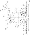
- numeral 58 indicates an apparatus configured for applying gasketing elements 38 to respective chassis 12.
- the apparatus 58 comprises a gripping device 60, an inlet conveyor 62, an inlet transfer roller 64, an outlet conveyor 66, an outlet transfer roller 68, and a cut-and-slip unit 70.
- the inlet conveyor 62 advances an array of chassis 12 without the gasketing elements 38 in the direction indicated by the arrow 72.
- the array of chassis 12 may be a continuous array.
- the array of chassis 12 may be formed by discrete chassis 12 spaced apart from each other.
- the chassis 12 are oriented with the respective longitudinal axes X parallel to the direction of advancement 72 and are arranged with the respective topsheets 24 facing upwards.
- the gripping device 60 may comprise a central disc 74 rotatable around a first rotation axis 76 and two side discs 78 rotatable around respective second rotation axes 80 inclined in directions opposite to each other with respect to the central disc 74.
- the central disc 74 may be omitted and the gripping device 60 may only include the two side discs 78.
- the central disc 74 and the two side discs 78 have respective circumferential surfaces 82, 84 provided with gripping elements 86, 88 configured for gripping the side portions 14 and the central portions 16 of the chassis 12, respectively.
- the gripping elements 86, 88 may include suction holes connected to a suction source.
- the gripping elements 86, 88 may include belts or tapes cooperating with the respective circumferential surfaces 82, 84 of the central disc 74 and of the side discs 78 to hold the side portions 14 and the central portions 16 of the chassis 12 in contact with circumferential surfaces 82, 84.
- the inlet transfer roller 64 picks up the chassis 12 from the inlet conveyor 62 and transfers them to the gripping device 60 in a gripping area 90.
- the central portions 16 of the chassis 12 are gripped by the gripping elements 84 of the central disc 74 and the side portions 14 of the chassis 12 are gripped by the gripping elements 86 of the side discs 78.
- the side discs 78 of the gripping device 60 are in a position spaced apart from each other.
- the cut-and-slip unit 70 includes an anvil roller 92 to which a continuous elastic sheet 94 is fed in a direction 96 parallel to its longitudinal axis.
- the continuous elastic sheet 94 is elastically extensible in a direction transverse to its longitudinal axis.
- the continuous elastic sheet 94 fed to the cut-and-slip unit 70 may come from a reel or may be produced in line starting from reels of elastic film and reels of non-woven fabric coupled together to form an elastic laminate.
- the cut-and-slip unit 70 comprises a knife roller 98 that cooperates with the anvil roller 92 to transversely cut the continuous elastic sheet 94. After cutting, successive gasketing elements 38 are formed on the outer surface of the anvil roller 92 and are held on the outer surface of the anvil roller 92, for example, by suction. The gasketing members 38 are held on the outer surface of the anvil roller 92 in an untensioned state in the transverse direction.
- the anvil roller 92 has a peripheral speed greater than the feeding speed of the continuous elastic sheet 94 so that, after cutting, the gasketing elements 38 on the outer surface of the anvil roller 92 are spaced apart from each other in the direction of advancement.
- a glue dispensing device 100 may be arranged upstream of the anvil roller 92, configured to apply a pattern of glue on the continuous elastic sheet 94.
- each of the gasketing elements 38 may have a C-shaped glue layer on its surface, with two side glue strips adjacent to the side edges 44 and a transverse glue strip adjacent to the outer transverse edge 40.
- the anvil roller 92 transfers the gasketing elements 38 to the gripping device 60 in an application area 102 in positions spaced apart from each other in the longitudinal direction. In the application area 102 the gasketing elements 38 are in a non-tensioned state in the transverse direction.
- the side discs 78 of the gripping device 60 are in a position close to each other.
- the side portions 14 of the chassis 12 are brought close together in a transversal direction.
- the chassis 12 may assume a concave shape with the central portions 16 of the chassis 12 located in a lowered position with respect to the side portions 14.
- the anvil roller 92 applies the gasketing elements 38 in a non-tensioned condition in a transverse direction to respective chassis 12 while the side portions 14 of the chassis 12 are approached to each other.
- the outer side edges 44 of the gasketing elements 38 are applied to corresponding side portions 14 of the respective chassis 12 while the side portions 14 are approached to each other.
- the outer side edges 44 of the gasketing elements 38 may be fixed by glue to the corresponding side portions 14 of the chassis 12.
- the chassis 12 advance towards a detachment area 104, in which the outlet transfer roller 68 picks up the chassis 12 equipped with respective gasketing elements 38 and transfers them onto the outlet conveyor 66.
- the side discs 78 of the gripping device 60 move away from each other in a transverse direction. Therefore, the chassis 12 are brought from the concave configuration they have in the application station 102 to an extended configuration in the detachment station 104, as illustrated in Figure 6 .
- the gasketing elements 38 are elastically stretched in the transverse direction.
- the outer transverse edges 40 of the gasketing elements 38 are fixed to the respective chassis 12 while the chassis 12 are in an extended position.
- the attachment of the gasketing elements 38 to the chassis 12 may be carried out by thermal or ultrasonic welding, as an alternative or in addition to fixing by glue.
- Finished absorbent sanitary articles 10 in an extended position are collected on the outlet conveyor 66, which can then be folded and packaged according to methods known in the field.
- the rear and front waist sections 18, 20 are stretched around the user's waist.
- the gasketing element 38 is stretched elastically in the transverse direction Y before closing the absorbent sanitary article 10 around the user's waist by the closure formations 32.
- the inner transverse edge 42 of the gasketing element 38 detaches from the surface of the topsheet 24 or the waistband 34. This ensures that, when the absorbent sanitary article 10 is worn, the pocket 50 formed between the gasketing element 38 and the topsheet 24 or the waistband 34 is open and in the best conditions for receiving and containing solid or semi-solid body exudates remaining between the skin of the user and the topsheet 22.
- the absorbent sanitary article 10 may have a single gasketing element 38 located in only one of the waist sections 18 or 20 (for example, the rear waist section 18, which is the one most exposed to receiving solid or semi-solid body exudates) or it may comprise two gasketing elements 38, each configured as previously described and located, respectively, in the rear waist section 18 and in the front waist section 20.
- the apparatus 58 previously described during operation implements a method comprising:
- the method may also envisage returning the chassis 12 to an extended configuration after attaching the side edges 44 of the gasketing elements 38 to the side portions of the chassis 12.
- the method may involve attaching the outer transverse edges 40 of the gasketing elements 38 to the chassis 12 after the chassis 12 have been returned to the extended configuration.
Landscapes
- Health & Medical Sciences (AREA)
- Engineering & Computer Science (AREA)
- Heart & Thoracic Surgery (AREA)
- Epidemiology (AREA)
- Biomedical Technology (AREA)
- Vascular Medicine (AREA)
- Life Sciences & Earth Sciences (AREA)
- Animal Behavior & Ethology (AREA)
- General Health & Medical Sciences (AREA)
- Public Health (AREA)
- Veterinary Medicine (AREA)
- Manufacturing & Machinery (AREA)
- Mechanical Engineering (AREA)
- Absorbent Articles And Supports Therefor (AREA)
Abstract
Description
- The present invention relates to a method for producing absorbent sanitary articles such as, for example, diapers, diaper-pants, incontinence pads for incontinent adults, etc.
- The present invention also relates to an apparatus for producing absorbent sanitary articles.
- Absorbent sanitary articles typically have a central body or chassis having a rear section, a front section and a crotch section extending between the rear section and the front section and extending between the user's legs in the condition that the absorbent sanitary article is worn. The chassis normally comprises a topsheet of liquid-permeable material intended to come into contact with the user's skin when the article is worn, a backsheet of impermeable material and an absorbent core sandwiched between the topsheet and the backsheet. The rear section and the front section of the chassis are normally closed around the waist of the user by at least one pair of side panels which project laterally beyond the side edges of the chassis. The side panels may be elastically extensible in the transverse direction.
- One of the most common problems with absorbent sanitary articles is the possibility that bodily exudates may leak from the rear or front waist section of the absorbent article. The risk of leakage is higher in the case of semi-solid fecal material that is not absorbed by the absorbent core and that can leak from the space between the waistband of the absorbent sanitary article and the user's skin.
- Various solutions have already been proposed in the state of the art, which tend to limit the risk of leakage of solid or semi-solid bodily exudates from the front or rear waist sections of an absorbent sanitary article. One such solution is described in
US 2020/0038256 A1 . This document discloses an absorbent sanitary article including a chassis and at least one gasketing element applied to the topsheet and having an outer transverse edge attached to the topsheet and an inner transverse edge detached from the topsheet so that, during use, the gasketing element forms a pocket facing the crotch section of the chassis, which may receive and contain solid or semi-solid exudates. - The known solutions that envisage the use of a gasketing element as described in
US 2020/0038256 A1 do not work correctly if the gasketing element remains adherent to the surface of the topsheet in the condition wherein the absorbent sanitary article is worn. Indeed, in this case the pocket formed between the gasketing element and the topsheet remains closed, and the gasketing element is not in a condition to receive and contain solid or semi-solid exudates. - The known solutions often have problems in ensuring a correct detachment of the inner transverse edge of the gasketing element from the surface of the topsheet in the condition wherein the absorbent sanitary article is worn.
- The object of the present invention is to provide a method for producing absorbent sanitary articles that solves the problems of the prior art
- According to the present invention, this object is achieved by a method having the characteristics forming the subject of claim 1.
- According to another aspect, the invention relates to an apparatus for producing absorbent sanitary articles having the characteristics forming the subject of claim 9.
- Preferred embodiments of the invention form the subject of the dependent claims.
- The claims form an integral part of the disclosure provided here in relation to the invention.
- The present invention will now be described in detail with reference to the attached drawings, given purely by way of non-limiting example, wherein:
-
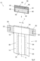
Figure 1 is a schematic plan view of an absorbent sanitary article in an extended position, -
Figure 2 is a schematic perspective view of the part indicated by the arrow II inFigure 1 , -
Figure 3 is a schematic side view of an embodiment of an apparatus according to the present invention, -
Figure 4 is a schematic front view according to the arrow IV ofFigure 3 , -
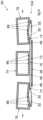
Figures 5 and6 are schematic cross-sections according to the lines V-V and VI-VI ofFigure 3 , and -
Figures 7 and8 are schematic views corresponding toFigures 1 and2 and illustrating a second embodiment of an absorbent sanitary article. - It will be appreciated that the accompanying drawings are schematic and that - in certain figures - some components may not be shown to assist in understanding the Figures. It will be appreciated that the various figures may also not be represented on the same scale.
- With reference to
Figures 1 and2 ,numeral 10 indicates a possible embodiment of an absorbent sanitary article that can be produced with a method and apparatus according to the present invention. - The absorbent
sanitary article 10 comprises achassis 12 elongated along a longitudinal axis X. Thechassis 12 has twoside portions 14 and acentral portion 16. - The
chassis 12 may have a rectangular shape as illustrated inFigure 1 , in which the edges of theside portions 14 are straight and parallel to the longitudinal axis X. In a possible embodiment, the edges of theside portions 14 may be curved and shaped so as to conform to the user's legs in the configuration wherein the absorbentsanitary article 10 is worn. In this case, thechassis 12 may have substantially an hourglass shape. - The
chassis 12 has arear waist section 18, afront waist section 20 and acrotch section 22, which extends between therear waist section 18 and thefront waist section 20. In a configuration of use, the rear andfront waist sections crotch section 22 extends between the legs of the user. - The
chassis 12 comprises atopsheet 24 constituted by a sheet of liquid-permeable material and having an outer surface which - during use - is in contact with the user's skin. Thechassis 12 further comprises an impermeable backsheet 26 (Figure 2 ) and anabsorbent core 28, which is sandwiched between thetopsheet 24 and thebacksheet 26. - The absorbent
sanitary article 10 may comprise at least one pair ofside panels 30 extending laterally outwards fromrespective side portions 14 of thechassis 12 in at least one of the rear and/orfront waist sections side panels 30 may have an elastic portion elastically extensible along a transverse direction Y orthogonal to the longitudinal axis X.Closure formations 32, for example, micro-hook closure formations, may be attached to the distal ends of theside panels 30. - In the case wherein the absorbent
sanitary article 10 has only one pair of side panels (usually a pair of rear side panels) the waist section opposite to the one carrying the pair ofside panels 30 may have a micro-loop front panel on its outer surface for establishing surface closure withmicro-hook closure formations 32. - In a possible embodiment illustrated in
Figures 7 and8 , theside panels 30 may be formed by outer portions of awaistband 34 fixed to therear waist section 18 of thechassis 12. Thewaistband 34 may be elastically stretchable in the transverse direction Y and may be attached to thetopsheet 24. - The absorbent
sanitary article 10 may comprise twoleg cuffs 36. The twoleg cuffs 36 may be formed by respective strips elongated in the direction of the longitudinal axis X and located alongrespective side portions 14 of thechassis 12. Theleg cuffs 36 may have respective outer edges attached to thechassis 12 and respective inner edges detached from the inner surface of thetopsheet 24 and elastically tensioned, so that the inner edges of theleg cuffs 36 in the configuration of use are elastically held in contact with the user's legs and form barriers that help to reduce the leakage of liquid, solid or semi-solid bodily exudates into thecrotch section 22 of thechassis 12. - The absorbent
sanitary article 10 comprises at least onegasketing element 38 fixed on the side of thechassis 12 facing the user during use in at least one of the rear andfront waist sections sanitary article 10 comprises asingle gasketing element 38 located in therear waist section 18. In possible embodiments, the absorbentsanitary article 10 could comprise a rear gasketing element located in therear waist section 18 and a front gasketing element located in thefront waist section 20. - The
gasketing element 38 may have the shape of a rectangular strip elongated in the transverse direction Y. Thegasketing element 38 is elastically extendable in the transverse direction Y. - In a possible embodiment, the
gasketing element 38 may consist of a single layer of an elastic film. In a possible embodiment, thegasketing element 38 may be formed of a composite elastic material, for example, an elastic laminate including an elastic film sandwiched between two non-woven layers anchored to each other and to the elastic film by a pattern of connecting points formed by glue or welding (thermal or ultrasonic). In a possible embodiment, thegasketing element 38 may comprise a plurality of elastic threads or a plurality of elastic tapes sandwiched between two non-woven layers anchored to each other and to the elastic threads or tapes elastic by means of a pattern of connecting points formed by glue or welding (thermal or ultrasonic). - With reference to
Figure 2 , thegasketing element 38 comprises an outertransverse edge 40, an innertransverse edge 42 and twoside edges 44. Thegasketing element 38 is fixed to thechassis 12 along atransverse attachment area 46 adjacent to the outertransverse edge 40 and along twolongitudinal attachment areas 48 adjacent to therespective side edges 44. - The
attachment areas gasketing element 38 and thechassis 12 having a substantially C shape facing thecrotch section 22 of thechassis 12. The innertransverse edge 42 of thegasketing element 38 is detached from the surface of thechassis 12 so as to form apocket 50 open towards thecrotch section 22 of thechassis 12. Thepocket 50 is closed on three sides by theattachment areas attachment areas - In the event that the
chassis 12 includes awaistband 34 attached to thetopsheet 24, thegasketing element 38 may be attached to thewaistband 34. Thewaistband 34 may have non-elastic areas at theattachment areas - If a
waistband 34 is not provided, thegasketing element 38 may be attached to thetopsheet 24 and to the end areas of the leg cuffs 36. - With reference to
Figures 3 and4 , numeral 58 indicates an apparatus configured for applyinggasketing elements 38 torespective chassis 12. - The
apparatus 58 comprises agripping device 60, aninlet conveyor 62, aninlet transfer roller 64, anoutlet conveyor 66, anoutlet transfer roller 68, and a cut-and-slip unit 70. - The
inlet conveyor 62 advances an array ofchassis 12 without thegasketing elements 38 in the direction indicated by thearrow 72. In a possible embodiment the array ofchassis 12 may be a continuous array. In a possible embodiment the array ofchassis 12 may be formed bydiscrete chassis 12 spaced apart from each other. On theinlet conveyor 62 thechassis 12 are oriented with the respective longitudinal axes X parallel to the direction ofadvancement 72 and are arranged with therespective topsheets 24 facing upwards. - With reference to
Figure 4 , the grippingdevice 60 may comprise acentral disc 74 rotatable around afirst rotation axis 76 and twoside discs 78 rotatable around respective second rotation axes 80 inclined in directions opposite to each other with respect to thecentral disc 74. In possible embodiments, thecentral disc 74 may be omitted and thegripping device 60 may only include the twoside discs 78. - The
central disc 74 and the twoside discs 78 have respectivecircumferential surfaces gripping elements side portions 14 and thecentral portions 16 of thechassis 12, respectively. Thegripping elements gripping elements circumferential surfaces central disc 74 and of theside discs 78 to hold theside portions 14 and thecentral portions 16 of thechassis 12 in contact withcircumferential surfaces - The fact that the two
side discs 78 rotate aroundrotation axes 80 inclined to each other means that thegripping elements 88 of theside discs 78 move cyclically in a transverse direction between a spaced apart position and a close together position, and vice versa. - The
inlet transfer roller 64 picks up thechassis 12 from theinlet conveyor 62 and transfers them to thegripping device 60 in a grippingarea 90. Thecentral portions 16 of thechassis 12 are gripped by thegripping elements 84 of thecentral disc 74 and theside portions 14 of thechassis 12 are gripped by thegripping elements 86 of theside discs 78. In the grippingarea 90 theside discs 78 of thegripping device 60 are in a position spaced apart from each other. When thechassis 12 are gripped by the grippingdevice 60 in the grippingarea 90 they are in an extended position. - The cut-and-
slip unit 70 includes ananvil roller 92 to which a continuouselastic sheet 94 is fed in adirection 96 parallel to its longitudinal axis. The continuouselastic sheet 94 is elastically extensible in a direction transverse to its longitudinal axis. The continuouselastic sheet 94 fed to the cut-and-slip unit 70 may come from a reel or may be produced in line starting from reels of elastic film and reels of non-woven fabric coupled together to form an elastic laminate. - The cut-and-
slip unit 70 comprises aknife roller 98 that cooperates with theanvil roller 92 to transversely cut the continuouselastic sheet 94. After cutting,successive gasketing elements 38 are formed on the outer surface of theanvil roller 92 and are held on the outer surface of theanvil roller 92, for example, by suction. Thegasketing members 38 are held on the outer surface of theanvil roller 92 in an untensioned state in the transverse direction. - The
anvil roller 92 has a peripheral speed greater than the feeding speed of the continuouselastic sheet 94 so that, after cutting, thegasketing elements 38 on the outer surface of theanvil roller 92 are spaced apart from each other in the direction of advancement. - A
glue dispensing device 100 may be arranged upstream of theanvil roller 92, configured to apply a pattern of glue on the continuouselastic sheet 94. After the transverse cut, each of thegasketing elements 38 may have a C-shaped glue layer on its surface, with two side glue strips adjacent to the side edges 44 and a transverse glue strip adjacent to the outertransverse edge 40. - The
anvil roller 92 transfers thegasketing elements 38 to thegripping device 60 in anapplication area 102 in positions spaced apart from each other in the longitudinal direction. In theapplication area 102 thegasketing elements 38 are in a non-tensioned state in the transverse direction. - In the
application area 102, theside discs 78 of thegripping device 60 are in a position close to each other. With reference toFigure 5 , in theapplication area 102, theside portions 14 of thechassis 12 are brought close together in a transversal direction. Following the transversal approach of theside portions 14, thechassis 12 may assume a concave shape with thecentral portions 16 of thechassis 12 located in a lowered position with respect to theside portions 14. - The
anvil roller 92 applies thegasketing elements 38 in a non-tensioned condition in a transverse direction torespective chassis 12 while theside portions 14 of thechassis 12 are approached to each other. The outer side edges 44 of thegasketing elements 38 are applied to correspondingside portions 14 of therespective chassis 12 while theside portions 14 are approached to each other. The outer side edges 44 of thegasketing elements 38 may be fixed by glue to thecorresponding side portions 14 of thechassis 12. - With reference to
Figure 3 , after applying thegasketing elements 38 to therespective chassis 12 in theapplication area 102, thechassis 12 advance towards adetachment area 104, in which theoutlet transfer roller 68 picks up thechassis 12 equipped withrespective gasketing elements 38 and transfers them onto theoutlet conveyor 66. - During the journey from the
application area 102 towards thedetachment area 104, theside discs 78 of thegripping device 60 move away from each other in a transverse direction. Therefore, thechassis 12 are brought from the concave configuration they have in theapplication station 102 to an extended configuration in thedetachment station 104, as illustrated inFigure 6 . - During the stretching in the transverse direction of the
chassis 12, thegasketing elements 38 are elastically stretched in the transverse direction. The outertransverse edges 40 of thegasketing elements 38 are fixed to therespective chassis 12 while thechassis 12 are in an extended position. - In a possible embodiment, the attachment of the
gasketing elements 38 to thechassis 12 may be carried out by thermal or ultrasonic welding, as an alternative or in addition to fixing by glue. - Finished absorbent
sanitary articles 10 in an extended position are collected on theoutlet conveyor 66, which can then be folded and packaged according to methods known in the field. - When an absorbent
sanitary article 10 is worn, the rear andfront waist sections gasketing element 38 is stretched elastically in the transverse direction Y before closing the absorbentsanitary article 10 around the user's waist by theclosure formations 32. - During the elastic stretching in the transverse direction of the
gasketing element 38, the innertransverse edge 42 of thegasketing element 38 detaches from the surface of thetopsheet 24 or thewaistband 34. This ensures that, when the absorbentsanitary article 10 is worn, thepocket 50 formed between thegasketing element 38 and thetopsheet 24 or thewaistband 34 is open and in the best conditions for receiving and containing solid or semi-solid body exudates remaining between the skin of the user and thetopsheet 22. - As indicated above, the absorbent
sanitary article 10 may have asingle gasketing element 38 located in only one of thewaist sections 18 or 20 (for example, therear waist section 18, which is the one most exposed to receiving solid or semi-solid body exudates) or it may comprise twogasketing elements 38, each configured as previously described and located, respectively, in therear waist section 18 and in thefront waist section 20. - The
apparatus 58 previously described during operation implements a method comprising: - providing an array of
chassis 12 having rear andfront waist sections - advancing the array of
chassis 12 in the direction of their longitudinal axes X, - gripping
side portions 14 of thechassis 12 in extended positions and approaching theside portions 14 to each other in a transverse direction, - providing an array of
gasketing elements 38 elastically extensible in a transverse direction and having respective side edges 44, - applying and fixing side edges 44 of the
gasketing elements 38 toside portions 14 of thechassis 12 while thegasketing elements 38 are not stretched in a transverse direction and while theside portions 14 of thechassis 12 are approached to each other. - The method may also envisage returning the
chassis 12 to an extended configuration after attaching the side edges 44 of thegasketing elements 38 to the side portions of thechassis 12. - The method may involve attaching the outer
transverse edges 40 of thegasketing elements 38 to thechassis 12 after thechassis 12 have been returned to the extended configuration. - Applying and attaching the gasketing element to the chassis in an elastically unstretched state in the transverse direction simplifies the process and apparatus considerably. The attachment of the gasketing elements to the side portions of the chassis while these side portions are approached to each other ensures that the inner transverse edges of the gasketing elements are elastically stretched in the transverse direction in the condition wherein the absorbent sanitary articles are worn, so that the pockets formed by the gasketing elements are open and in the best conditions to receive and contain solid or semi-solid body exudates remaining between the user's skin and the topsheet.
- Of course, without prejudice to the principle of the invention, the details of construction and the embodiments can be widely varied with respect to those described and illustrated, without thereby departing from the scope of the invention as defined by the claims that follow.
Claims (10)
- A method for producing absorbent sanitary articles (10), comprising:- providing an array of chassis (12) having rear and front waist sections (18, 20) and respective longitudinal axes (X),- advancing said array of chassis (12) in the direction of said longitudinal axes (X),- gripping side portions (14) of said chassis (12) in extended positions and approaching said side portions (14) to each other in a transverse direction,- providing an array of gasketing elements (38) elastically extensible in a transverse direction and having respective side edges (44),- applying and fixing side edges (44) of said gasketing elements (38) to side portions (14) of said chassis (12) while the gasketing elements (38) are not stretched in a transverse direction and while said side portions (14) of said chassis (12) are approached to each other.
- The method of claim 1, comprising returning said chassis (12) to an extended configuration after fixing said side edges (44) of said gasketing elements (38) to said side portions (14) of said chassis (12).
- The method of claim 2, comprising fixing outer transverse edges (40) of said gasketing elements (38) to said chassis (12) after said chassis (12) have been brought back to an extended configuration.
- The method according to any of the preceding claims, comprising:- providing a continuous elastic web (94) movable in the direction of its longitudinal axis,- transversely cutting said continuous elastic web (94) so as to form a plurality of gasketing elements (38),- spacing apart said gasketing elements (38) from each other in the longitudinal direction and applying said gasketing elements (38) to said array of chassis (12) .
- The method according to any of the preceding claims, comprising:- providing a pair of side discs (78) rotatable around respective axes of rotation (80) inclined to each other,- gripping side portions (14) of said chassis (12) on circumferential surfaces (84) of side discs (78) in a gripping area (90) in which said side discs (78) are spaced apart from each other,- applying said gasketing elements (38) to said chassis (12) in an application area (102) in which said side discs (78) are close to each other.
- The method of claim 5, comprising detaching said chassis (12) from said side discs (78) in a detachment area (104) in which said side discs (78) are spaced apart from each other.
- The method according to claim 5 or claim 6, comprising:- providing a central disc (74) arranged between said side discs (78) and rotatable around an axis of rotation (76), wherein the axes of rotation (80) of said side discs (78) are inclined in opposite directions with respect to the axis of rotation (76) of said central disc (74),- gripping central portions (16) of said chassis (12) on a circumferential surface (82) of said central disc (74) and holding said chassis (12) in a concave configuration in said application area (102).
- The method of any of the preceding claims wherein said array of chassis (12) is a continuous array.
- An apparatus for producing absorbent sanitary articles (10), comprising:- an inlet conveyor (62) configured to advance an array of chassis (12) in the direction of their longitudinal axes (X),- a gripping device (60) configured to grip side portions (14) of said chassis (12) in extended positions and approach said side portions (14) to each other in a transverse direction,- a cut-and-slip unit (70) configured to form an array of gasketing elements (38) elastically extendable in the transverse direction and having respective side edges (44) and to apply and fix side edges (44) of said gasketing elements (38) to side portions (14) of said chassis (12) while the gasketing elements (38) are not stretched in the transverse direction and while said side portions (14) of said chassis (12) are approached to each other.
- The apparatus of claim 9, wherein said gripping device (60) comprises a pair of side discs (78) rotatable around respective axes of rotation (80) inclined to each other and having circumferential surfaces (84) provided with gripping elements (88), wherein in a gripping area (90) said side discs (78) are spaced apart from each other in a transverse direction and wherein in an application area (102) said side discs (78) are approached to each other.
Applications Claiming Priority (1)
| Application Number | Priority Date | Filing Date | Title |
|---|---|---|---|
| IT102022000021942A IT202200021942A1 (en) | 2022-10-25 | 2022-10-25 | Process and equipment for the production of absorbent sanitary articles |
Publications (1)
| Publication Number | Publication Date |
|---|---|
| EP4360605A1 true EP4360605A1 (en) | 2024-05-01 |
Family
ID=84943462
Family Applications (1)
| Application Number | Title | Priority Date | Filing Date |
|---|---|---|---|
| EP23204147.5A Pending EP4360605A1 (en) | 2022-10-25 | 2023-10-17 | A method and apparatus for producing absorbent sanitary articles |
Country Status (3)
| Country | Link |
|---|---|
| US (1) | US12527696B2 (en) |
| EP (1) | EP4360605A1 (en) |
| IT (1) | IT202200021942A1 (en) |
Citations (1)
| Publication number | Priority date | Publication date | Assignee | Title |
|---|---|---|---|---|
| US20200038256A1 (en) | 2015-09-29 | 2020-02-06 | Kimberly-Clark Worldwide, Inc. | Absorbent article with selectively positioned waist containment member having an improved waist seal |
Family Cites Families (4)
| Publication number | Priority date | Publication date | Assignee | Title |
|---|---|---|---|---|
| US4240866A (en) * | 1979-10-18 | 1980-12-23 | Johnson & Johnson Baby Products Company | Apparatus for manufacturing a product having elastic means disposed in the transverse direction |
| US5102486A (en) * | 1991-01-09 | 1992-04-07 | Minnesota Mining And Manufacturing Company | Loop applying assembly |
| US5755902A (en) * | 1996-12-05 | 1998-05-26 | Kimberly Clark Corporation | Method and apparatus for producing a composite web having transverse stretch |
| US6197138B1 (en) * | 1998-12-29 | 2001-03-06 | Kimberly-Clark Worldwide, Inc. | Machine and process for placing and bonding elastic members in a relaxed state to a moving substrate web |
-
2022
- 2022-10-25 IT IT102022000021942A patent/IT202200021942A1/en unknown
-
2023
- 2023-10-17 EP EP23204147.5A patent/EP4360605A1/en active Pending
- 2023-10-24 US US18/492,899 patent/US12527696B2/en active Active
Patent Citations (1)
| Publication number | Priority date | Publication date | Assignee | Title |
|---|---|---|---|---|
| US20200038256A1 (en) | 2015-09-29 | 2020-02-06 | Kimberly-Clark Worldwide, Inc. | Absorbent article with selectively positioned waist containment member having an improved waist seal |
Also Published As
| Publication number | Publication date |
|---|---|
| IT202200021942A1 (en) | 2024-04-25 |
| US12527696B2 (en) | 2026-01-20 |
| US20240225914A9 (en) | 2024-07-11 |
| US20240130900A1 (en) | 2024-04-25 |
Similar Documents
| Publication | Publication Date | Title |
|---|---|---|
| US10143597B2 (en) | Method and apparatus for applying elastic parts under tension to an advancing carrier | |
| JP6096108B2 (en) | Method and apparatus for tucking side panels of absorbent articles | |
| EP2280679B1 (en) | Methods and apparatus for attaching elastic components to absorbent articles | |
| EP2555730B1 (en) | Methods and apparatuses for tucking side panels of absorbent articles | |
| JP6250832B2 (en) | Method and apparatus for making an absorbent article having a contoured belt | |
| US8617341B2 (en) | Methods for assembling disposable diaper pants | |
| EP3811916B1 (en) | A method and apparatus for producing absorbent sanitary articles and relative absorbent sanitary article | |
| JPH04161152A (en) | Disposable absorptive article and its manufacture | |
| WO1995018589A1 (en) | Elastomeric disposable absorbent article and method of making same | |
| EP2377499A1 (en) | Method of manufacturing absorptive article | |
| US12616612B2 (en) | Absorbent sanitary article and a method for producing the same | |
| US12527696B2 (en) | Method and apparatus for producing absorbent sanitary articles | |
| EP4295826B1 (en) | An absorbent sanitary article and method for its production | |
| EP4159172B1 (en) | An absorbent sanitary article and a method for producing the same | |
| JP6395763B2 (en) | Absorbent articles | |
| JPH0615622U (en) | Disposable diapers | |
| MXPA01005987A (en) | Pant-like disposable absorbent articles with an easy opening feature |
Legal Events
| Date | Code | Title | Description |
|---|---|---|---|
| PUAI | Public reference made under article 153(3) epc to a published international application that has entered the european phase |
Free format text: ORIGINAL CODE: 0009012 |
|
| STAA | Information on the status of an ep patent application or granted ep patent |
Free format text: STATUS: THE APPLICATION HAS BEEN PUBLISHED |
|
| AK | Designated contracting states |
Kind code of ref document: A1 Designated state(s): AL AT BE BG CH CY CZ DE DK EE ES FI FR GB GR HR HU IE IS IT LI LT LU LV MC ME MK MT NL NO PL PT RO RS SE SI SK SM TR |
|
| STAA | Information on the status of an ep patent application or granted ep patent |
Free format text: STATUS: REQUEST FOR EXAMINATION WAS MADE |
|
| 17P | Request for examination filed |
Effective date: 20240912 |
|
| RBV | Designated contracting states (corrected) |
Designated state(s): AL AT BE BG CH CY CZ DE DK EE ES FI FR GB GR HR HU IE IS IT LI LT LU LV MC ME MK MT NL NO PL PT RO RS SE SI SK SM TR |
|
| GRAP | Despatch of communication of intention to grant a patent |
Free format text: ORIGINAL CODE: EPIDOSNIGR1 |
|
| STAA | Information on the status of an ep patent application or granted ep patent |
Free format text: STATUS: GRANT OF PATENT IS INTENDED |
|
| INTG | Intention to grant announced |
Effective date: 20250911 |
|
| STAA | Information on the status of an ep patent application or granted ep patent |
Free format text: STATUS: THE APPLICATION IS DEEMED TO BE WITHDRAWN |