EP4360441A1 - Multi pass unloading operation - Google Patents
Multi pass unloading operation Download PDFInfo
- Publication number
- EP4360441A1 EP4360441A1 EP23202822.5A EP23202822A EP4360441A1 EP 4360441 A1 EP4360441 A1 EP 4360441A1 EP 23202822 A EP23202822 A EP 23202822A EP 4360441 A1 EP4360441 A1 EP 4360441A1
- Authority
- EP
- European Patent Office
- Prior art keywords
- landing point
- pass
- receiving vehicle
- fill level
- vehicle
- Prior art date
- Legal status (The legal status is an assumption and is not a legal conclusion. Google has not performed a legal analysis and makes no representation as to the accuracy of the status listed.)
- Pending
Links
Images






Classifications
-
- A—HUMAN NECESSITIES
- A01—AGRICULTURE; FORESTRY; ANIMAL HUSBANDRY; HUNTING; TRAPPING; FISHING
- A01D—HARVESTING; MOWING
- A01D41/00—Combines, i.e. harvesters or mowers combined with threshing devices
- A01D41/12—Details of combines
- A01D41/127—Control or measuring arrangements specially adapted for combines
- A01D41/1275—Control or measuring arrangements specially adapted for combines for the level of grain in grain tanks
-
- A—HUMAN NECESSITIES
- A01—AGRICULTURE; FORESTRY; ANIMAL HUSBANDRY; HUNTING; TRAPPING; FISHING
- A01D—HARVESTING; MOWING
- A01D41/00—Combines, i.e. harvesters or mowers combined with threshing devices
- A01D41/12—Details of combines
- A01D41/1208—Tanks for grain or chaff
- A01D41/1217—Unloading mechanisms
-
- A—HUMAN NECESSITIES
- A01—AGRICULTURE; FORESTRY; ANIMAL HUSBANDRY; HUNTING; TRAPPING; FISHING
- A01D—HARVESTING; MOWING
- A01D43/00—Mowers combined with apparatus performing additional operations while mowing
- A01D43/06—Mowers combined with apparatus performing additional operations while mowing with means for collecting, gathering or loading mown material
- A01D43/07—Mowers combined with apparatus performing additional operations while mowing with means for collecting, gathering or loading mown material in or into a trailer
-
- B—PERFORMING OPERATIONS; TRANSPORTING
- B65—CONVEYING; PACKING; STORING; HANDLING THIN OR FILAMENTARY MATERIAL
- B65G—TRANSPORT OR STORAGE DEVICES, e.g. CONVEYORS FOR LOADING OR TIPPING, SHOP CONVEYOR SYSTEMS OR PNEUMATIC TUBE CONVEYORS
- B65G67/00—Loading or unloading vehicles
- B65G67/02—Loading or unloading land vehicles
- B65G67/04—Loading land vehicles
- B65G67/22—Loading moving vehicles
-
- A—HUMAN NECESSITIES
- A01—AGRICULTURE; FORESTRY; ANIMAL HUSBANDRY; HUNTING; TRAPPING; FISHING
- A01D—HARVESTING; MOWING
- A01D43/00—Mowers combined with apparatus performing additional operations while mowing
- A01D43/08—Mowers combined with apparatus performing additional operations while mowing with means for cutting up the mown crop, e.g. forage harvesters
Definitions
- the present description generally relates to machines that load material into receiving vehicles, such as harvesting machines that fill carts, semitrailers, or other agricultural or other receiving vehicles. More specifically, but not by limitation, the present description relates to automated control of a fill-to-weight unloading operation.
- Some such vehicles include agricultural vehicles such as forage harvesters or other harvesters (such as combine harvesters, sugarcane harvesters, silage harvesters, etc.), that harvest grain or other crop. Such harvesters often unload material into carts, which may be pulled by tractors, or semitrailers, as the harvesters are moving.
- Other vehicles that unload material into receiving vehicles include construction vehicles, such as cold planers that unload into a dump truck, and other vehicles.
- a semitruck or tractor-pulled cart (a receiving vehicle) is often in position relative to the harvester (e.g., alongside the harvester or behind the harvester) so that the harvester can fill the semitrailer or cart, while moving through the field.
- this requires the operator of the harvester to control the position of the unloading spout and flap so that the truck or cart is filled evenly, but not over filled. Even a momentary misalignment between the spout and the truck or cart may result in hundreds of pounds of harvested material being dumped on the ground, rather than in the truck or cart.
- a leading vehicle loads material into a receiving vehicle during an unloading operation.
- the unloading operation loads the receiving vehicle according to a multi-pass fill pattern.
- an automatic cart filling control system uses a stereo camera on the spout of the harvester to capture an image of the receiving vehicle.
- An image processing system detects material height within the receiving vehicle, in order to automatically aim the spout toward empty spots and control the flap position (and thus material trajectory) to achieve a more even fill, while reducing spillage.
- Such systems can fill the receiving vehicle according to a fill strategy (such as front-to-back, back-to-front, etc.) that is set by the operator or that is set in other ways.
- some current harvesters are provided with a machine synchronization control system.
- the harvester may, for instance, be a combine harvester so that the spout is not movable relative to the frame during normal unloading operations. Instead, the relative position of the receiving vehicle and the combine harvester is changed in order to fill the receiving vehicle as desired.
- a front-to-back fill strategy for instance, the relative position of the receiving vehicle, relative to the combine harvester, is changed so that the spout is first filling the receiving vehicle at the front end, and then gradually fills the receiving vehicle moving rearward.
- the combine harvester and receiving vehicle may have machine synchronization systems which communicate with one another.
- the machine synchronization system on the combine harvester can send a message to the machine synchronization system on the towing vehicle to nudge the towing vehicle slightly forward or rearward relative to the combine harvester, as desired.
- the machine synchronization system on the combine harvester may receive a signal from the fill control system on the combine harvester indicating that the position in the receiving vehicle that is currently being filled is approaching its desired fill level (fill height, fill weight, etc.). In that case, the machine synchronization system on the combine harvester can send a "nudge" signal to the machine synchronization system on the towing vehicle.
- the "nudge”, once received by the machine synchronization system on the towing vehicle, causes the towing vehicle to automatically momentarily speed up or slow down, thus nudging the position of the receiving vehicle forward or rearward, respectively, relative to the combine harvester.
- automatically it is meant, for example, that the operation is performed without further human involvement except, perhaps, to initiate or authorize the operation.
- leading vehicle will be the vehicle that is unloading material into the receiving vehicle.
- the term following vehicle will refer to the propulsion vehicle, or towing vehicle (such as a tractor), that is providing propulsion to the receiving vehicle (such as a cart).
- the material is unloaded from the leading vehicle into the receiving vehicle according to a fill pattern, such as a front-to-back fill pattern or a back-to-front fill pattern.
- a fill pattern such as a front-to-back fill pattern or a back-to-front fill pattern.
- the leading vehicle and the receiving vehicle are positioned relative to one another so that the material is first loaded into the receiving vehicle at a first landing point near the front portion of the receiving vehicle (in the direction of travel) to a desired fill level. Then, the following vehicle is nudged forward relative to the leading vehicle so that the next subsequent landing point of the material in the receiving vehicle is slightly rearward relative to the first landing point.
- the following vehicle is again nudged forward to move the subsequent landing point rearward in the receiving vehicle, and this continues until the receiving vehicle is filled to the desired fill level starting at the front of the receiving vehicle and moving toward the rear of the receiving vehicle.
- the fill pattern is opposite that of the front-to-back fill pattern. That is, the two vehicles are positioned relative to one another so that the initial landing point of the material in the receiving vehicle is at the rear of the receiving vehicle. When the material level at the initial landing point reaches the desired fill level, the following vehicle is nudged backward relative to the leading vehicle so that the next subsequent landing point in the receiving vehicle is just forward of the initial landing point. This continues until the receiving vehicle is filled to the desired fill level.
- the present description thus proceeds with respect to a system that implements a fill pattern in which material is initially placed at an initial landing point that is generally over the axle (and perhaps just forward of the of the axle) of the receiving vehicle.
- the fill control system then performs a forward pass, in which material is filled (moving in the forward direction in the receiving vehicle) until the entire forward portion of the receiving vehicle is filled to a first pass target fill height. This places some weight over the draw bar, but that weight is, to some extent, counter balanced by the weight that has already been placed over the axle.
- the unloading control system performs a second pass in which the receiving vehicle is filled with material to a desired final target fill height following a front-to-back fill pattern.
- the initial landing point can be configurable by an operator.
- the present system enforces a minimum nudge distance. Therefore instead of performing a large number of small nudges to fill the receiving vehicle, a minimum nudge distance is maintained which decreases the frequency of the nudge operations, thus reducing wear on the tractor and increasing the operator comfort for the operator of the following vehicle (the tractor).
- the present system can also implement a resumed filling operation which can be performed when the receiving vehicle is already partially filled by a previous unloading operation.
- the unloading control system performs the unloading operation to resume where the previous unloading operation finished without overfilling the receiving vehicle.
- FIG. 1 is a pictorial illustration showing one example of a self-propelled forage harvester 100 (a material loading vehicle also referred to as a leading vehicle) filling a tractor-pulled grain cart (or receiving vehicle) 102.
- Cart 102 thus defines an interior that forms a receiving vessel 103 for receiving harvested material through a receiving area 112.
- a tractor 104 a towing vehicle also referred to as a following vehicle
- forage harvester 100 has a detector such as camera 106 mounted on the spout 108 through which the harvested material 110 is traveling.
- the spout 108 can be pivotally or rotatably mounted to a frame 107 of harvester 100.
- the detector 106 is a stereo-camera or a mono-camera that captures an image (e.g., a still image or video) of the receiving area 112 of cart 102.
- the receiving area 112 is defined by an upper edge of the walls of cart 102.
- the automatic fill control system attempts to identify the location of the receiving area 112 by identifying the edges or walls of the receiving area and can then gauge the height of harvested material in cart 102, and the location of that material in the receiving vehicle.
- the system thus automatically controls the position of spout 108 and flap 109 to direct the trajectory of material 110 into the receiving area 112 of cart 102 to obtain an even fill throughout the entire length and width of cart 102, while not overfilling cart 102.
- automatically it is meant, for example, that the operation is performed without further human involvement except, perhaps, to initiate or authorize the operation.
- the automatic fill control system may attempt to move the spout and flap or a machine synchronization system can position the vehicles relative to one another so the material begins landing at a first landing point in the back of vessel 103 of receiving vehicle 102. Then, once a desired fill level is reached in the back of vessel 103, the automatic fill control system moves the spout and flap or the machine synchronization system nudges the receiving vehicle to change the position of the vehicles relative to one another so the material begins landing just forward of the first landing point in vessel 103.
- cart 102 may have a scale that generates a weight signal indicative of a weight of material loaded into cart 102.
- the weight signal can be communicated to the automated fill control system to control the fill operation based on the weight signal and/or based on the fill level. This enables receiving vehicle 102 to be filled according to a desired fill pattern without exceeding weight restrictions or limitations on receiving vehicle 102.
- FIG. 2 is a pictorial illustration showing another example of a self-propelled forage harvester 100, this time loading a semi-trailer (or receiving vessel on a receiving vehicle) 122 in a configuration in which a semi-tractor (also referred to as a following vehicle) is pulling semi-trailer 122 alongside forage harvester 100. Therefore, the spout 108 and flap 109 are positioned to unload the harvested material 110 to fill trailer 122 according to a pre-defined side-by-side fill strategy.
- FIG. 2 shows that camera 106 can capture an image (which can include a still image or video) of semi-trailer 122.
- FIG. 1 shows an image (which can include a still image or video) of semi-trailer 122.
- the field of view of camera 106 is directed toward the receiving area 120 of trailer 122 so that image processing can be performed to identify a landing point for the harvested material in trailer 122.
- a machine synchronization system can nudge the semi-trailer forward or rearward relative to harvester 100 to accomplish a fill strategy.
- Trailer 122 can also have a scale that sends a weight signal to the automated control system to control the unloading operation based on the weight signal.
- FIG. 3 shows an example in which leading vehicle 101 is a combine harvester, with an operators compartment 121 and with a header 130 that engages crop.
- the crop is processed and placed in a clean grain tank 132, where it is unloaded (such as using an auger) through spout 108 into a receiving vehicle 134 (e.g., a grain cart) that is pulled by a following vehicle 136 (e.g., a tractor).
- FIG. 3 shows that receiving vehicle 134 is coupled to following vehicle 136 at a hitch point, or pivot point, 137.
- harvester 101 is a combine harvester, it may be that the spout 108 is not moved relative to the frame of harvester 101 during normal unloading operations.
- the relative position of the receiving vehicle 134 and the combine harvester 101 is changed in order to fill the receiving vessel as desired.
- the relative position of the receiving vessel in receiving vehicle 134, relative to the combine harvester 101 is changed so that the spout 108 is first filling the receiving vehicle 134 at the front end, and then gradually fills the receiving vessel moving rearward.
- receiving vehicle 134 can have a scale that generates a weight signal.
- the automated system can control the unloading operation based on the weight signal alone or based on the weight signal in conjunction with other information, such as the height of material in the receiving material.
- the weight signal can be sent to the following vehicle 136 and then to the automated system (which may be on leading vehicle 101) or directly to the automated system.
- the weight signal can also be sent to a remote server and then to the loading vehicle 101.
- the communication channels can be wifi, cellular, and/or other communication channels.
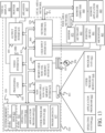
- FIG. 4 shows a block diagram illustrating one example of an agricultural system 140 which includes leading vehicle (in the present example, a combine harvester) 101 which is followed by following vehicle (in the present example, a tractor or another propulsion vehicle) 136. Following vehicle 136 is pulling a receiving vehicle 134.
- leading vehicle in the present example, a combine harvester
- following vehicle in the present example, a tractor or another propulsion vehicle
- receiving vehicle 134 e.g., the vehicles shown in the example illustrated in FIG. 3
- other leading vehicles, following vehicles, and receiving vehicles can be used as well.
- the example shown in FIG. 4 is shown for the sake of example only.
- FIG. 4 also shows that leading vehicle 101, following vehicle 136, and/or receiving vehicle 134 can communicate with one or remote systems 153 (which can be a remote server environment, such as a vendor system, a manufacturer system, a farm manager system, a cloud-based system, or another system) over a network 155.
- Network 155 can be a wifi network, a cellular network, a Bluetooth network, a wide or local area network, or other network or combination of networks.
- Leading vehicle 101 includes one or more processors or servers 142, data store 144, sensor(s) 145 (which can include optical sensor 147, position sensor 146, and other sensors 149), communication system 148, fill level (height/weight) detector(s) 162, unloading control system 150, operator interface system 154, controllable subsystems 156, and other vehicle functionality 158.
- Unloading control system 150 can include vehicle position detector(s) 160, subsystem controller 165, and other control system functionality 166.
- Vehicle position detector(s) 160 can include an optical sensor, a RADAR sensor, a LIDAR sensor, and/or other sensors.
- An optical sensor can include camera 106, an image processor, and/or other items.
- Fill pattern controller 163 can include initial value identifier 168, first pass controller 170, second pass controller 172, resume loading processor 176, and other items 178.
- Resume loading processor 176 can include pass selector 180, location selector 182, material level processor 184, output generator 186, and other items 188.
- Controllable subsystems 156 can include material conveyance subsystem (e.g., blower, auger, spout, flap, etc.) 192, propulsion/steering subsystem 194, harvesting subsystem 196, and/or other items 198.
- FIG. 4 also shows that leading vehicle 101 can be operated by an operator 200 by interacting with an operator interface and/or operator interface mechanism(s).
- vehicle 136 can include position sensor 204, communication system 206, one or more processors or servers 208, data store 210, control system 212, operator interface system 214, and any of a wide variety other functionality 216.
- FIG. 4 also shows that following vehicle 136 may be operated by operator 218 who can interact with interfaces 219 (generated by operator interface system 214) and/or with other operator interface mechanisms.
- Position sensor 146 can be a global navigation satellite system (GNSS) receiver, a dead reckoning system, a cellular triangulation system, or any of a wide variety of other systems that identify the coordinates or location of leading vehicle 101 in a global or local coordinate system.
- Optical sensor 147 can be a camera 106 or other optical sensor along with an image processing system.
- Data store 144 can store dimension information and orientation information, such as information that identifies the location and orientation of optical sensor 106 relative to the material conveyance system (e.g., blower, auger, spout, flap, etc.) 192.
- Data store 144 can store other information as well, such as volume profile information corresponding to receiving vehicle 134, an initial landing point, an initial fill height, a desired final fill height, a fill height buffer, a nudge size threshold, and other information.
- Communication system 148 enables the communication of items on vehicle 101 with other items on vehicle 101, as well as communication with following vehicle 136, vehicle 134, remote system(s) 153, and/or other communication. Therefore, communication system 148 can be a controller area network (CAN) bus and bus controller, a cellular communication device, a wifi communication device, a local or wide area network communication device, a Bluetooth communication device, and/or any of a wide variety of devices or systems that enable communication over different types of networks or combinations of networks.
- CAN controller area network
- Fill level (height/weight, etc.) detector 162 can detect the fill level (e.g., the fill height or weight) of material in receiving vehicle 134.
- the fill level detector 162 can receive a signal from camera 106 and an image processing system that detects the level of material in receiving vehicle 134 relative to the top edge of receiving vehicle 134 and identify the fill height at the current landing point and at other points in receiving vehicle 134.
- Fill level detector 162 may receive a weight signal from scale on receiving vehicle 134 and identify the fill level of material in receiving vehicle 134 based on the weight signal and any estimated or measured density metric indicative of the density of the material.
- Fill level detector 162 can detect the fill level in other ways as well.
- Unloading control system 150 controls the unloading process by which material conveyance subsystem 192 conveys material from leading vehicle 101 to receiving vehicle 134.
- Vehicle position detectors 160 sense parameters indicative of the position of the receiving vehicle 134.
- detectors 160 can detect structural portions of receiving vehicle 134 that allow the location of the receiving area of receiving vehicle 134 to be determined.
- the structural portions for example, may be the front wall or top front edge of the receiving vehicle 134, the side walls or top side edges of receiving vehicle 134, the rear wall or the top rear edge of receiving vehicle 134, etc. Therefore, vehicle position detectors 160 can include a camera 106 (or other camera(s)) and an image processor or other detectors.
- vehicle position detector(s) 160 can include a RADAR sensor, and/or a LIDAR sensor, and/or other sensor(s). Such sensors can have signal processing systems that process the signals generated by RADAR and LIDAR sensors and/or other sensor(s) to identify the receiving vehicle parameters. Detector(s) 160 can include other sensors and processing systems as well.
- Vehicle position detectors 160 can detect or derive the position of leading vehicle 101 and following vehicle 136 either in terms of absolute coordinates within a global or local coordinate system, or in terms of a relative position in which the positions of vehicles 101 and 136 are determined relative to one another. For instance, vehicle position detector(s) 160 can receive an input from position sensor 146 on vehicle 101 and from position sensor 204 (which may also be a GNSS receiver, etc.) on following vehicle 136 to determine where the two vehicles are located relative to one another.
- position sensor 146 on vehicle 101
- position sensor 204 which may also be a GNSS receiver, etc.
- Vehicle position detector(s) 160 can then use known dimension information and/or kinematic information (which may, for instance, indicate the location and orientation of camera 106 or other detectors on the vehicles relative to known reference points on the vehicle or relative to the material conveyance subsystem 192, etc.) to detect the location of receiving vehicle 134 relative to the material conveyance subsystem 192. This location can then be used to determine how to control vehicles 101 and 136 to perform an unloading operation so that material conveyance subsystem 192 loads material into receiving vehicle 134 according to a desired fill pattern.
- known dimension information and/or kinematic information which may, for instance, indicate the location and orientation of camera 106 or other detectors on the vehicles relative to known reference points on the vehicle or relative to the material conveyance subsystem 192, etc.
- Fill pattern controller 163 generates control signals that can be used to control vehicle 101 and following vehicle 136 to accomplish the desired fill pattern. For instance, fill pattern controller 163 can generate control signals to control the material conveyance subsystem 192 to start or stop material conveyance, to control the spout position or flap position in order to control the trajectory of material that is being conveyed to receiving vehicle 134, and/or to control the propulsion/steering subsystem 194. Fill pattern controller 163 can also generate control signals that are sent by communication system 148 to the following vehicle 136 to "nudge" the following vehicle forward or rearward relative to leading vehicle 101, to instruct the operator 218 of following vehicle 136 to perform a desired operation, or to generate other control signals.
- fill pattern controller 163 may receive an input from fill level detector 162 that is indicative of the fill level of material in receiving vehicle 134 at the current landing point in receiving vehicle 134.
- the fill level detector 162 can detect the fill level of material at the current landing point using camera 106 and an image processing system.
- a nudge may be issued to following vehicle 136 in order to move the position of the landing point where material is being conveyed to receiving vehicle 134 to a different landing point, in order to accomplish a desired fill pattern.
- a nudge may be issued to move receiving vehicle 134 forward relative to material conveyance subsystem 192, to thus move the landing point rearward in receiving vehicle 134.
- fill pattern controller 163 controls the fill pattern to initially fill material in the central portion of receiving vehicle 134, such as over its axle. Then, the fill pattern continues along a first pass by filling receiving vehicle 134 moving forward toward the front wall of receiving vehicle 134, to an initial target fill height which is perhaps one meter or some other height between the floor and the top edge of receiving vehicle 134. The first pass thus places weight on the hitch point 252, but the initial weight has been placed over the axle of receiving vehicle 134.
- the fill pattern continues along a second pass by filling receiving vehicle 134 at the forward landing point to the final or desired target fill height (which may be within a threshold distance of the top of receiving vehicle 134), and then moving rearward performing a front-to-back fill pattern so that the receiving vehicle 134 is evenly filled to the desired or, final target fill height.
- This type of multi-pass filling operation enhances the stability of the vehicles by initially placing weight over the axle (or just forward of the axle) of the receiving vehicle 134 and then placing weight over the hitch point, and finally moving rearward to fill the receiving vehicle 134 to the final target fill height in the second front-to-back pass.
- Subsystem controller 165 can generate control signals to control any desired controllable subsystems 156, communication system 148, etc.
- operator interface system 154 can generate interfaces for operator 200 and receive inputs from operator 200. Therefore, operator interface system 154 can include interface mechanisms such as a steering wheel, joysticks, pedals, buttons, displays, levers, linkages, etc. interfaces can be generated for interaction by operator 200, such as on a display screen, a touch sensitive display screen, or in other ways. Operator interface system 154 can detect operator interactions with the displayed interface, such as the operator actuating icons, links, buttons, etc. Operator 200 can interact with the interface(s) using a keyboard or keypad, a point and click device, touch gestures, speech commands (where speech recognition and/or speech synthesis are provided), or in other ways.
- position sensor 204 may be a global navigation satellite system (GNSS) receiver, a dead reckoning system, a cellular triangulation system, or any of a wide variety of other systems that provide coordinates of following vehicle 136 in a global or local coordinate system, or that provide an output indicating the position of following vehicle 136 relative to a reference point (such as relative to leading vehicle 101), etc.
- Communication system 206 allows the communication of items on vehicle 136 with one another, and also provides for communication with leading vehicle 101, receiving vehicle 134, remote system(s) 153, and/or other systems. Therefore, communication system 206 can be similar to communication system 148 discussed above, or different.
- Data store 210 can store dimension data which identify different dimensions of following vehicle 136, the location and/or orientation of different sensors on vehicle 136, kinematic information describing vehicle 134 and/or vehicle 136, and other information.
- Control system 212 can be used to receive inputs and generate control signals. The control signals can be used to control communication system 206, operator interface system 214, data store 210, the propulsion and/or steering subsystem on following vehicle 136, other controllable subsystems, and/or other items.
- Operator interface system 214 can also include an interface generator that can generate interfaces 219.
- Operator interface system 214 can also include operator interface mechanisms such as a steering wheel, joysticks, buttons, levers, pedals, linkages, etc.
- Operator interface system 214 can also include a display screen that can be used to display operator interfaces 219 for interaction by operator 218.
- Operator 218 can interact with the operator interfaces using a point and click device, touch gestures, voice commands, etc.
- Network 155 may be a wide area network, a local area network, a near field communication network, a wifi communication network, a cellular communication network, a Bluetooth communication network, or any of a wide variety of other networks or combinations of networks. Therefore, any of the communication systems in system 140 may be configured to communicate over network 155.
- a data store on remote system(s) 153 can store volume profile information for different receiving vehicles, any of the initial values discussed above, among other things.
- FIG. 5A is a pictorial illustration of one example of a receiving vehicle 134 and following vehicle (e.g., tractor) 136.
- vehicle e.g., tractor
- three different initial landing points are identified to show where the unloading operation can begin.
- the material is initially loaded at a front location 250.
- the weight on the hitch point 252 of vehicle 136 and receiving vehicle 134 increases. If the weight is sufficient, the structure forming the hitch point 252 (e.g., the hitch bar of vehicle 134 and/or draw bar of vehicle 136) may actually break.
- the initial landing point could be the point indicated at 252 in FIG. 5A , toward the rear of receiving vehicle 134.
- the weight can increase thus inducing a moment about the axle of receiving vehicle 134 generally in the direction indicated by arrow 254. This can cause an upward force to be exerted on the hitch point 252. When the weight is sufficient, this can break the structures forming to hitch point 252 or lift the rear wheels of vehicle 136 off the ground.
- the initial landing point is set to be at or near landing point 254, over the axle (or just forward of the axle) of vehicle 134.
- the receiving vehicle 134 is filled to an initial target fill level at landing point 254, and vehicle 136 is then nudge rearwardly relative to leading vehicle 101 so that the landing point moves forward in receiving vehicle 134.
- FIG. 5B shows one example of this. In FIG. 5B , it can be seen that material has been filled at initial landing point 254 to an initial target fill level 256. Then, the vehicle 136 is nudged rearwardly so that the next subsequent landing point is generally at landing point 250, closer to the front of receiving vehicle 136.
- a deadband zone is set relative to the front wall 258 of receiving vehicle 134.
- the deadband zone is illustrated by dashed line 260 and identifies a boundary that is spaced (by a predefined or configurable distance) from front wall 258 across which the landing point will not be moved. The landing point will be no closer to front wall 258 than the boundary identified by deadband 260. This helps to avoid accidental material spillage forward of the front wall 258 during the fill operation.
- FIG. 5C shows that material has now been loaded into receiving vehicle 134 to the initial target fill height 256 from the initial landing point 254 all the way forward to the deadband location 260.
- the unloading operation then continues at landing point 250 until the material reaches a final or desired target fill height as indicated by the dashed line 262. Once the material reaches the final target fill height 262 at location 250, then vehicle 136 is nudged forward relative to leading vehicle 101 so that the landing point moves rearwardly in receiving vehicle 134.
- FIG. 5D shows an example of this.
- FIG. 5D shows that the material at landing point 250 has now reached the final or desired target fill height 262.
- vehicle 136 is nudged forward relative to leading vehicle 101 so that the next subsequent landing point is landing point 264. This continues so that once material at landing point 264 reaches the desired target fill height 262, receiving vehicle 136 is again nudged forward so that the next subsequent landing point is landing point 266. Again, when the material at landing point 266 reaches desired target fill height 264, receiving vehicle 136 is again nudged forward so that the next subsequent landing point is landing point 268. This continues until the material at the different landing points in receiving vehicle 134 is loaded to the final target fill height 262.
- a deadband 270 for the rear wall 272 of receiving vehicle 134 may be used so that the landing point where material is filled into receiving vehicle 134 stays between deadbands 260 and 270 to avoid spillage of material rearward of wall 272.
- initial value identifier 168 identifies the initial values that are needed to load material according to a fill pattern.
- the initial value identifier may identify such things as the initial landing point (e.g., 254 in FIG. 5A ), the initial target fill height (e.g., 256 in FIG. 5B ), the desired, final target fill height (e.g., 262 in FIG. 5C ), a fill height buffer (which is described in greater detail below), a nudge size threshold (which is also described in greater detail below), and/or a wide variety of other initial values.
- initial value identifier 168 receives the initial values through an operator input.
- the initial values can be obtained from data store 144 or other locations.
- First pass controller 170 then controls the unloading operation to perform the first pass (such as the forward pass described above with respect to FIGS. 5A-5D .
- Second pass controller 172 controls the unloading operation to perform the second pass (such as the rearward pass described above with respect to FIGS. 5A-5D ).
- resume loading processor 176 identifies an initial landing point where vehicle 101 can resume filling receiving vehicle 134.
- Processor 176 thus attempts to identify where, in the multi-pass unloading operation, the previous operation finished.
- Pass selector 180 identifies the pass that the previous leading vehicle was on when it finished unloading.
- Location selector 182 identifies the landing point in receiving vehicle 134 where the current unloading operation is to resume filling receiving vehicle 134. For example, it may be that the previous unloading operation finished part way through the first, forward pass or partially through the second, rearward pass.
- pass selector 180 can determine which pass to resume. Also, by detecting the fill levels, location selector 182 can identify the landing point (on the first or second pass) where unloading is to resume. Material level processor 184 identifies the level of material in receiving vehicle 134 and provides that level to pass selector 180 and location selector 182 to determine where the unloading operation should resume and output generator 186 generates an output identifying where the unloading operation is to resume, and which pass is to be resumed. For instance, if the unloading operation is to resume at location 250 (shown above with respect to FIGS.
- output generator 186 outputs the landing point location 250 along with the pass (e.g., whether the unloading operation should commence filling and continue the forward pass or the rearward pass). That information can be output to first pass controller 170 or second pass controller 172 to resume loading the receiving vehicle 134 at a desired location and on a desired pass.
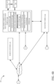
- FIG. 6 is a flow diagram illustrating one example of the operation of agricultural system 140 in performing a multi-pass fill operation. It is first assumed that leading vehicle 101 is to begin performing an unloading operation to unload material into receiving vehicle 134, as indicated by block 273.
- Initial value identifier 168 then identifies initial values that will be used in performing the unloading operation. Identifying initial values is indicated by block 274 in the flow diagram of FIG. 6 . Some or all of the initial values may be preset of default values, as indicated by block 278. The initial values may be obtained automatically as indicated by block 280 or through operator inputs as indicated by block 282. The initial values may include such things as the initial landing location 284 that identifies the landing point in receiving vehicle 134 where the unloading operation is to begin.
- the initial values may include an initial target fill height 286 for the forward pass (such as initial target fill height 256 shown in FIGS. 5A-5D ).
- the initial values may include the desired or final target fill height 288 (such as fill height 262 shown in FIGS. 5C and 5D ), a fill height buffer 290 which identifies a height below the desired final target fill height 262, and a nudge size threshold 292 which identifies the minimum distance between landing points during the fill operation.
- the initial values can include a wide variety of other values 294 as well.
- fill level detector 162 determines whether the receiving vehicle is empty, or partially filled. If receiving vehicle 134 is partially filled, then resume loading processor 176 identifies the landing location and pass to resume unloading material into receiving vehicle 134, as indicated by block 298.
- Fill pattern controller 163 controls movement of the two vehicles relative to one another so that the material conveyance subsystem 192 is positioned to begin loading material into receiving vehicle 134 at the identified landing location, as indicated by block 300. If leading vehicle 101 is to resume unloading material into receiving vehicle 134 according to the first pass, as determined at block 302, then processing moves to block 304 where the first pass is resumed. However, if leading vehicle 101 is to resume loading receiving vehicle 134 according to the second pass, then processing jumps to block 306 where the second pass is resumed.
- initial value identifier 168 identifies the initial landing point where the unloading operation is to commence, as indicated by block 308 in the flow diagram of FIG. 6 .
- the initial landing point can, as discussed above, be automatically determined as a location between, and offset from, the front and rear walls of receiving vehicle 134, as indicated by block 310. In another example, the initial landing point may be identified based upon the location of the axle of receiving vehicle 134 (which may be obtained from dimension information, kinematic information, or other information that corresponds to receiving vehicle 134).
- Determining the initial landing point based upon the location of the axle of receiving vehicle 134 is indicated by block 312 in the flow diagram of FIG. 6 .
- the initial landing point may be determined based upon an operator input, as indicated by block 314.
- a graphical user interface may be displayed for operator 200 or for operator 218.
- the graphical user interface may display actuatable user input mechanisms which allow the operator to set the initial landing point for the unloading operation.
- the graphical user interface may include a pictorial illustration of receiving vehicle 134 and allow the operator to specify the location in receiving vehicle 134 corresponding to the initial landing point using a touch gesture or another input.
- the graphical user interface may include a movable element (e.g., a slider) that is movable along an axis corresponding to the front-to-back axis of receiving vehicle 134.
- the movable element may be a slidable thumb, a numerical value with "+" and "-" actuators, or another indicator that can be used to select the initial landing point.
- the initial landing point can be identified in a wide variety of other ways as well, as indicated by block 316 in the flow diagram of FIG. 6 .
- first pass controller 170 controls the unloading operation to fill the initial landing location to the initial target fill height, as indicated by block 318 in the flow diagram of FIG. 6 . For instance, as shown in FIG. 5B , first pass controller 170 controls the unloading operation to fill the initial fill location 254 to the initial target fill height 256.
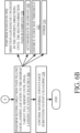
- first pass controller 170 performs an unloading pass in the first direction (e.g., toward the front wall 258 of receiving vehicle 134) nudging the vehicle 136 backward relative to the leading vehicle 101 to fill each subsequent landing point to the initial target fill height 256 until the front wall 258 (or the deadband 260) is reached, as indicated by block 304 in the flow diagram of FIG. 6 .
- first pass controller 170 controls the nudges so that the nudges are only performed in one direction (e.g., vehicle 136 is only nudged rearward relative to leading vehicle 101 during the first pass) until the entire first pass is completed.
- the material in the receiving vehicle may settle so that material at a landing point behind the current landing point (in the direction of the first pass) may fall below the desired fill level.
- the system will not re-visit that landing point, because it is in the opposite direction of the current pass. This inhibits the following vehicle being nudged in opposite directions during a given pass.
- Performing nudges in one direction during the first pass is indicated by block 320 in the flow diagram of FIG. 6 .
- Accommodating the deadband 260 so that the unloading operation does not perform unloading at a landing point forward of the deadband 260 is indicated by block 322 in the flow diagram of FIG. 6 .
- a minimum nudge size or nudge threshold is set so that a next subsequent landing point is at least a threshold distance from the current landing point.
- the frequency of the nudge operations is governed by the minimum nudge size threshold. Setting a smaller nudge size threshold means that more nudges will be performed more often during unloading. This can lead to a more even fill of receiving vehicle 134 but also reduced comfort for operator 218 and more wear on vehicle 136. Setting a larger nudge size threshold means fewer and less frequent nudges will be performed.
- Allowing a configurable nudge size threshold can ensure that the receiving vehicle 134 will be filled relatively uniformly, but the comfort of the operator of following vehicle 136 is also accommodated because the nudge operations will not be performed too frequently.
- the nudge threshold is set to 60 cm. Therefore, even though the fill level detector 162 detects that a landing point 30 cm from the current landing point is not filled to the desired target fill level, the next landing point will be set 60 cm away from the current landing point. Enforcing the nudge size threshold is indicated by block 324 in the flow diagram of FIG. 6 .
- first pass controller 170 determines that the current landing point is at, or is approaching, the initial target fill level. First pass controller 170 will then identify the next subsequent landing point adjacent the current landing point where the fill level is below the fill level (or first pass target fill level) 256. First pass controller 170 will then set the next subsequent landing point to be at that identified point within receiving vehicle 134 so that vehicle 136 can be nudged rearwardly until material is being filled at the next subsequent landing point.
- a minimum nudge size threshold may be enforced. Assume, for instance, that a minimum nudge size is 60 cm.
- first pass controller 170 compares the distance between the current landing point and the identified landing point (40 cm) to the nudge size threshold (60 cm) and sets the nudge size to the larger of the two. The nudge size will thus be set to 60 cm so that the next subsequent landing point will be 60 cm away from the current landing point.
- First pass controller 170 controls the unloading operation so that vehicle 136 is nudged rearward relative to leading vehicle 101 by a distance of 60 cm (instead of 40 cm). Enforcing such a minimum nudge size threshold not only improves the comfort of the operator of vehicle 136, but it also ensures that receiving vehicle 134 is filled relatively evenly.
- First pass controller 170 can control the unloading operation to perform the first pass in other ways as well, as indicated by block 326.
- second pass controller 172 begins controlling the unloading operation to perform the second pass (which, in the example described herein, is a front-to-back pass).
- second pass controller 172 continues filling receiving vehicle 134 at the forward-most landing point 250 (shown in FIG. 5C ) until the material reaches the desired final fill height 262, at which point second pass controller 172 identifies a next subsequent landing point (rearward of the current landing point in receiving vehicle 134) where the material fill level has not yet reached the final target fill level 262.
- Second pass controller 172 controls the unloading operation so that vehicle 136 is nudged forward relative to leading vehicle 101 to position the material conveyance subsystem 192 so that it is now unloading at the next subsequent landing point located rearward of the current landing point.
- the next landing point 264 is identified and the vehicles are nudged relative to one another to continue loading at landing point 264.
- filling each landing point to the final target fill height is indicated by block 306 in the flow diagram of FIG. 6 . This continues until all identified landing points in receiving vehicle 134 are filled to the desired fill height 262.
- second pass controller 172 controls the unloading operation so that nudges are only performed in one direction during the second pass. Nudges in the opposite direction are locked out until the second direction pass is complete. This avoids nudging vehicle 136 forward and then rearward, and then forward, etc. Performing nudges in one direction until the second pass is complete is indicated by block 328 in the flow diagram of FIG. 6 . Also, second pass controller 172 can accommodate the deadband 270 to avoid inadvertently spilling material over the rear wall 272 of receiving vehicle 134. Accommodating deadband 270 is indicated by block 330 in the flow diagram of FIG. 6 .
- Second pass controller 172 can also enforce the minimum nudge size threshold to ensure that the frequency of the nudge operations is not undesirably high but to still fill receiving vehicle 136 uniformly, as indicated by block 332 in the flow diagram of FIG. 6 . Second pass controller 172 can control the second pass in other ways as well, as indicated by block 334.
- subsystem controller 165 controls the material conveyance subsystem 192 to stop unloading material, as indicated by block 338 in the flow diagram of FIG. 6 .
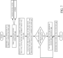
- FIG. 7 is a flow diagram shown one example of the operation of fill pattern controller 163 in controlling the fill operation according to a fill pattern.
- FIG. 7 shows one example of how first pass controller 170 can perform the first pass in filling receiving vehicle 134 and/or how second pass controller 172 can perform the second pass in filling receiving vehicle 134. It is first assumed that a fill operation is being performed at a current landing point within receiving vehicle 134. In such an example, fill pattern controller 163 is generating control signals that can be used to control material conveyance subsystems 192 and to nudge following vehicle 136 forward or rearward with respect to leading vehicle 101. Performing a fill operation at a current landing point is indicated by block 350 in the flow diagram of FIG. 7 .
- FIG. 7 describes the operation of second pass controller 172 performing the second pass (the front-to-back pass) in filling receiving vehicle 134.
- fill level detector 162 detects that the fill level at the current landing point in receiving vehicle 134 has reached the desired target fill level 262.
- Second pass controller 172 determines that it is time to perform a nudge operation commanding following vehicle 136 to move forward relative to leading vehicle 101. Determining that it is time to perform a nudge operation is indicated by block 352 in the flow diagram of FIG. 7 .
- Second pass controller 172 identifies a next subsequent landing point adjacent the current landing point in receiving vehicle 134 (in the direction of the second pass) where the material fill level is below the desired target fill level 262. For instance, fill level detector 162 can process an image of the receiving vehicle 134 to identify a landing point in receiving vehicle 134, closest to the current landing point but spaced from the current landing point in the direction of the second pass (in the front-to-rear direction), where the fill level is below the desired target fill level 262. Identifying the next subsequent landing point in receiving vehicle 134 where the target fill level is below the desired fill level 262 is indicated by block 354 in the flow diagram of FIG. 7 .
- Second pass controller 172 then calculates the distance between the current landing point and the next subsequent landing point to determine the distance of the nudge operation (e.g., the distance by which following vehicle 136 is to be nudged forward relative to leading vehicle 101). Calculating the nudge size in this way is indicated by block 356 in the flow diagram of FIG. 7 . Second pass controller 172 then compares the calculated nudge size to the minimum nudge size threshold, as indicated by block 358 in the flow diagram of FIG. 7 . If the calculated nudge size meets the minimum nudge size threshold, then processing continues at block 360 where second pass controller 172 generates control signals to nudge vehicle 136 by the calculated nudge size.
- the distance of the nudge operation e.g., the distance by which following vehicle 136 is to be nudged forward relative to leading vehicle 101. Calculating the nudge size in this way is indicated by block 356 in the flow diagram of FIG. 7 . Second pass controller 172 then compares the calculated nudge size to the minimum nudge size
- second pass controller 172 determines that the calculated nudge size is less than the minimum nudge size threshold, then the nudge size is set to the minimum nudge size threshold, as indicated by block 362 in the flow diagram of FIG. 7 , and the nudge is then performed to nudge vehicle 136 by the nudge size threshold, as indicated by block 360.
- the pass controller also enforces the deadbands 260 and 270 so that no landing points in the deadband zones are selected.
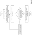
- FIG. 8 is a flow diagram showing one example of the operation of unloading control system 150 (and specifically of resume loading processor 176) in determining where to resume loading a receiving vehicle 134 that is already partially filled. For example, assume that a receiving vehicle 134 was partially filled during a previous unloading operation by a harvester when the harvester finished unloading. At that point, assume that receiving vehicle 134 was then brought to leading vehicle 101 to be loaded. Referring to FIG. 6 , at block 296, unloading control system 150 may receive a signal from fill level detector 162 indicating that receiving vehicle 134 is not completely empty, but is instead partially filled. Resume loading processor 176 then identifies where, in receiving vehicle 134, the initial landing point should be and what pass to perform in order to resume filling receiving vehicle 134. This can present some difficulties. FIG. 5E shows one example of such difficulties.
- resume loading processor 176 identifies the initial location where filling of receiving vehicle 134 is to be resumed by implementing a fill level buffer 390.
- Fill level buffer 390 may be a fixed value, or a dynamically calculated value, or a default value, or a value input by an operator, among other things.
- the buffer 390 defines a fill level that is below the desired fill level 262 by a buffer distance (such as 10 cm, 5 cm, etc.).
- resume loading processor 176 first identifies whether the reloading operation should be resumed on the first pass or the second pass. The pass can be identified based on the fill level at different points in the receiving vehicle 134.
- Processor 176 also identifies the location along that pass where the fill level of material at that location is less than the target fill level 262 and is also less than the fill level buffer 390.
- processor 176 will consider the region 382 as being adequately filled. Thus, processor 176 will identify a next landing point on the second pass where the fill level is below buffer 390. Processor 176 then identifies that landing point as the initial landing point (or landing location) where the unloading operation is to be resumed. In the example shown in FIG. 5E , it can be seen that landing point 386 is the first point where the fill level drops below the fill level buffer 390. Thus, landing point 386 is chosen as the location to resume filling of the receiving vehicle 134.
- resume loading processor 176 determines the fill level at different points along the first pass and then at different points along the second pass. Processor 176 thus can identify which landing point, and the pass, where the previous unloading operation finished and where the current unloading operation should be resumed. Therefore, pass selector 180 first selects which pass is being analyzed. Pass selector 180 can begin analyzing along the first pass to identify where material is filled to the initial target fill level 256 and then analyze along the second pass to identify where material is filled to the final target fill level 262. Assume, for the sake of the present discussion, that pass selector 180 has analyzed the first pass and determined that the first pass was completed during the previous unloading operation.
- Pass selector 180 selects the second pass so that resume loading processor 176 analyzes the fill level at different possible landing points along the second pass. Selecting a pass is indicated by block 392 in the flow diagram of FIG. 8 .
- location selector 182 identifies a first landing point in a sequence of landing points defined by the selected pass, as indicated by block 394. For instance, given that the second pass has been selected for analysis, then referring to FIG. 5D , location selector 182 may identify the first landing point in the second pass (landing point 250) to determine whether the fill level meets the desired target fill level 262 or the buffer 390.
- Material level processor 184 detects the fill level at the selected landing point 250 and determines whether the fill level at the identified landing point is filled to at least the fill height buffer 390. Having material level processor 184 detect the fill level at the selected landing point 250 is indicated by block 396. Determining whether the fill level meets the fill height buffer 390 is indicated by block 398 in the flow diagram of FIG. 8 . If the fill level at landing point 250 meets the fill height buffer 390, then location selector 182 selects a next landing point in receiving vehicle 134 (e.g., landing point 264) in the sequence of landing points defined by the second pass. Identifying a next landing point is indicated by block 400. Again, material level processor 184 determines whether material at landing point 264 meets the fill height buffer 390.
- Output generator 186 then outputs the identified landing point and the pass for resuming the fill operation.
- output generator 186 may generate an output identifying landing point 264 as the initial landing point and identifying the second pass as the pass on which to resume the unloading operation.
- second pass controller 172 receives the landing point 264 as the first landing point in the second pass for resuming the unloading operation.
- Second pass controller 172 then begins the second pass of the unloading operation to fill receiving vehicle 134, beginning at landing point 264 and then continuing to subsequent landing points along the second pass until the second pass is complete. Outputting the identified landing point or landing location and the pass for resuming the fill operation is indicated by block 400 in the flow diagram of FIG. 8 .
- the present description describes a system that performs a multi-pass unloading operation.
- the material can first be loaded into an initial landing location in receiving vehicle 134 which may be over the axle of receiving vehicle 134, slightly forward of the axle, etc.
- the present system then performs a forward pass filling receiving vehicle 134 to an initial target fill height which is below the final target fill height.
- the present system performs a second pass filling receiving vehicle 134 in a front-to-back pattern to the final target fill height.
- the present system can enforce a minimum nudge size threshold to control the frequency and size of the nudge operations.
- the present system can also incorporate a fill height buffer so that, when resuming a filling operation in a partially full receiving vehicle 134, the chances of overfilling the receiving vehicle are reduced.
- FIG. 9 is a block diagram illustrating agricultural system 140, shown in FIG. 4 , except that system 140 is disposed in a remote server architecture 500.
- remote server architecture 500 can provide computation, software, data access, and storage services that do not require end-user knowledge of the physical location or configuration of the system that delivers the services.
- remote servers can deliver the services over a wide area network, such as the internet, using appropriate protocols. For instance, remote servers can deliver applications over a wide area network and they can be accessed through a web browser or any other computing component.
- Software or components shown in previous FIGS. as well as the corresponding data, can be stored on servers at a remote location.
- the computing resources in a remote server environment can be consolidated at a remote data center location or they can be dispersed.
- Remote server infrastructures can deliver services through shared data centers, even though they appear as a single point of access for the user.
- the components and functions described herein can be provided from a remote server at a remote location using a remote server architecture.
- they can be provided from a conventional server, or they can be installed on client devices directly, or in other ways.
- FIG. 9 specifically shows that data stores 144, 210, 222, unloading control system 150, and other systems (such as analytics or processing systems) 504, can be located at a remote server location 502. Therefore, vehicles 101, 136 can access those systems through remote server location 502.
- FIG. 9 also depicts another example of a remote server architecture.
- FIG. 9 shows that it is also contemplated that some elements of FIG. 4 can be disposed at remote server location 502 while others are not.
- one or more of data stores 144, 210, 222, and other systems 504, or other items can be disposed at a location separate from location 502, and accessed through the remote server at location 502.
- the items can be accessed either directly by machine 101, 134, and/or machine 136, through a network (either a wide area network or a local area network), the items can be hosted at a remote site by a service, or the items can be provided as a service, or accessed by a connection service that resides in a remote location. Also, the data can be stored in substantially any location and intermittently accessed by, or forwarded to, interested parties. All of these architectures are contemplated herein.
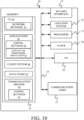
- FIG. 10 shows that other vehicles 506 can communicate with one or more vehicles 101, 136, or with remote server environment 502. It will also be noted that the elements of FIG. 4 , or portions of them, can be disposed on a wide variety of different devices. Some of those devices include servers, desktop computers, laptop computers, tablet computers, or other mobile devices, such as palm top computers, cell phones, smart phones, multimedia players, personal digital assistants, etc.
- FIG. 9 is a simplified block diagram of one illustrative example of a handheld or mobile computing device that can be used as a user's or client's hand held device 16, in which the present system (or parts of it) can be deployed.
- a mobile device can be deployed in the operator compartment of one or both of vehicles 101, 136 for use in generating, processing, or displaying the calibrated offset values.
- FIGS. 11-12 are examples of handheld or mobile devices.
- FIGS. 10 provides a general block diagram of the components of a client device 16 that can run some components shown in FIG. 4 , that interacts with them, or both.
- a communications link 13 is provided that allows the handheld device to communicate with other computing devices and in some examples provides a channel for receiving information automatically, such as by scanning. Examples of communications link 13 include allowing communication though one or more communication protocols, such as wireless services used to provide cellular access to a network, as well as protocols that provide local wireless connections to networks.
- SD Secure Digital
- Interface 15 and communication links 13 communicate with a processor 17 (which can also embody processors from previous FIGS.) along a bus 19 that is also connected to memory 21 and input/output (I/O) components 23, as well as clock 25 and location system 27.
- processor 17 which can also embody processors from previous FIGS.
- bus 19 that is also connected to memory 21 and input/output (I/O) components 23, as well as clock 25 and location system 27.
- I/O components 23 are provided to facilitate input and output operations.
- I/O components 23 for various examples of the device 16 can include input components such as buttons, touch sensors, optical sensors, microphones, touch screens, proximity sensors, accelerometers, orientation sensors and output components such as a display device, a speaker, and or a printer port.
- Other I/O components 23 can be used as well.
- Clock 25 illustratively comprises a real time clock component that outputs a time and date. It can also, illustratively, provide timing functions for processor 17.
- Location system 27 illustratively includes a component that outputs a current geographical location of device 16. This can include, for instance, a global positioning system (GPS) receiver, a dead reckoning system, a cellular triangulation system, or other positioning system. Location system 27 can also include, for example, mapping software or navigation software that generates desired maps, navigation routes and other geographic functions.
- GPS global positioning system
- Memory 21 stores operating system 29, network settings 31, applications 33, application configuration settings 35, data store 37, communication drivers 39, and communication configuration settings 41.
- Memory 21 can include all types of tangible volatile and non-volatile computer-readable memory devices.
- Memory 21 can also include computer storage media (described below).
- Memory 21 stores computer readable instructions that, when executed by processor 17, cause the processor to perform computer-implemented steps or functions according to the instructions.
- Processor 17 can be activated by other components to facilitate their functionality as well.
- FIG. 11 shows one example in which device 16 is a tablet computer 600.
- computer 600 is shown with user interface display screen 602.
- Screen 602 can be a touch screen or a pen-enabled interface that receives inputs from a pen or stylus.
- Tablet computer 600 can also use an on-screen virtual keyboard.
- computer 600 might also be attached to a keyboard or other user input device through a suitable attachment mechanism, such as a wireless link or USB port, for instance.
- Computer 600 can also illustratively receive voice inputs as well.
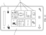
- FIG. 12 shows that the device can be a smart phone 71.
- Smart phone 71 has a touch sensitive display 73 that displays icons or tiles or other user input mechanisms 75. Mechanisms 75 can be used by a user to run applications, make calls, perform data transfer operations, etc.
- smart phone 71 is built on a mobile operating system and offers more advanced computing capability and connectivity than a feature phone.
- FIG. 13 is one example of a computing environment in which elements of FIG. 4 , or parts of it, (for example) can be deployed.
- an example system for implementing some embodiments includes a computing device in the form of a computer 810 programmed to operate as discussed above.
- Components of computer 810 may include, but are not limited to, a processing unit 820 (which can comprise processors from previous FIGS.), a system memory 830, and a system bus 821 that couples various system components including the system memory to the processing unit 820.
- the system bus 821 may be any of several types of bus structures including a memory bus or memory controller, a peripheral bus, and a local bus using any of a variety of bus architectures. Memory and programs described with respect to FIG. 4 can be deployed in corresponding portions of FIG. 13 .
- Computer 810 typically includes a variety of computer readable media.
- Computer readable media can be any available media that can be accessed by computer 810 and includes both volatile and nonvolatile media, removable and non-removable media.
- Computer readable media may comprise computer storage media and communication media.
- Computer storage media is different from, and does not include, a modulated data signal or carrier wave.
- Computer storage media includes hardware storage media including both volatile and nonvolatile, removable and non-removable media implemented in any method or technology for storage of information such as computer readable instructions, data structures, program modules or other data.
- Computer storage media includes, but is not limited to, RAM, ROM, EEPROM, flash memory or other memory technology, CD-ROM, digital versatile disks (DVD) or other optical disk storage, magnetic cassettes, magnetic tape, magnetic disk storage or other magnetic storage devices, or any other medium which can be used to store the desired information and which can be accessed by computer 810.
- Communication media may embody computer readable instructions, data structures, program modules or other data in a transport mechanism and includes any information delivery media.
- modulated data signal means a signal that has one or more of its characteristics set or changed in such a manner as to encode information in the signal.
- the system memory 830 includes computer storage media in the form of volatile and/or nonvolatile memory such as read only memory (ROM) 831 and random access memory (RAM) 832.
- ROM read only memory
- RAM random access memory
- BIOS basic input/output system 833
- RAM 832 typically contains data and/or program modules that are immediately accessible to and/or presently being operated on by processing unit 820.
- FIG. 13 illustrates operating system 834, application programs 835, other program modules 836, and program data 837.
- the computer 810 may also include other removable/non-removable volatile/nonvolatile computer storage media.
- FIG. 13 illustrates a hard disk drive 841 that reads from or writes to non-removable, nonvolatile magnetic media, an optical disk drive 855, and nonvolatile optical disk 856.
- the hard disk drive 841 is typically connected to the system bus 821 through a non-removable memory interface such as interface 840, and optical disk drive 855 are typically connected to the system bus 821 by a removable memory interface, such as interface 850.
- the functionality described herein can be performed, at least in part, by one or more hardware logic components.
- illustrative types of hardware logic components include Field-programmable Gate Arrays (FPGAs), Application-specific Integrated Circuits (e.g., ASICs), Application-specific Standard Products (e.g., ASSPs), System-on-a-chip systems (SOCs), Complex Programmable Logic Devices (CPLDs), etc.
- drives and their associated computer storage media discussed above and illustrated in FIG. 13 provide storage of computer readable instructions, data structures, program modules and other data for the computer 810.
- hard disk drive 841 is illustrated as storing operating system 844, application programs 845, other program modules 846, and program data 847. Note that these components can either be the same as or different from operating system 834, application programs 835, other program modules 836, and program data 837.
- a user may enter commands and information into the computer 810 through input devices such as a keyboard 862, a microphone 863, and a pointing device 861, such as a mouse, trackball or touch pad.
- Other input devices may include a joystick, game pad, satellite dish, scanner, or the like.
- a visual display 891 or other type of display device is also connected to the system bus 821 via an interface, such as a video interface 890.
- computers may also include other peripheral output devices such as speakers 897 and printer 896, which may be connected through an output peripheral interface 895.
- the computer 810 is operated in a networked environment using logical connections (such as a controller area network - CAN, local area network - LAN, or wide area network WAN) to one or more remote computers, such as a remote computer 880.
- logical connections such as a controller area network - CAN, local area network - LAN, or wide area network WAN
- remote computers such as a remote computer 880.
- the computer 810 When used in a LAN networking environment, the computer 810 is connected to the LAN 871 through a network interface or adapter 870. When used in a WAN networking environment, the computer 810 typically includes a modem 872 or other means for establishing communications over the WAN 873, such as the Internet. In a networked environment, program modules may be stored in a remote memory storage device. FIG. 13 illustrates, for example, that remote application programs 885 can reside on remote computer 880.
Landscapes
- Life Sciences & Earth Sciences (AREA)
- Environmental Sciences (AREA)
- Engineering & Computer Science (AREA)
- Aviation & Aerospace Engineering (AREA)
- Mechanical Engineering (AREA)
- Control Of Position, Course, Altitude, Or Attitude Of Moving Bodies (AREA)
Abstract
Description
- The present description generally relates to machines that load material into receiving vehicles, such as harvesting machines that fill carts, semitrailers, or other agricultural or other receiving vehicles. More specifically, but not by limitation, the present description relates to automated control of a fill-to-weight unloading operation.
- There are a wide variety of different types of vehicles that load material into other vehicles. Some such vehicles include agricultural vehicles such as forage harvesters or other harvesters (such as combine harvesters, sugarcane harvesters, silage harvesters, etc.), that harvest grain or other crop. Such harvesters often unload material into carts, which may be pulled by tractors, or semitrailers, as the harvesters are moving. Other vehicles that unload material into receiving vehicles include construction vehicles, such as cold planers that unload into a dump truck, and other vehicles.
- Taking an agricultural harvester as an example, while harvesting in a field using a forage harvester or combine harvester, an operator attempts to control the harvester to maintain harvesting efficiency, during many different types of conditions. The soil conditions, crop conditions, etc. can all change. This may result in the operator changing control settings. This means the operator needs to devote a relatively large amount of attention to controlling the forage harvester or combine harvester.
- At the same time, a semitruck or tractor-pulled cart (a receiving vehicle), is often in position relative to the harvester (e.g., alongside the harvester or behind the harvester) so that the harvester can fill the semitrailer or cart, while moving through the field. In some current systems, this requires the operator of the harvester to control the position of the unloading spout and flap so that the truck or cart is filled evenly, but not over filled. Even a momentary misalignment between the spout and the truck or cart may result in hundreds of pounds of harvested material being dumped on the ground, rather than in the truck or cart.
- A leading vehicle loads material into a receiving vehicle during an unloading operation. The unloading operation loads the receiving vehicle according to a multi-pass fill pattern.
-
-
FIG. 1 is a pictorial illustration of one example of a forage harvester filling a tractor-pulled receiving vehicle, with the receiving vehicle following the forage harvester. -
FIG. 2 is a pictorial illustration of one example of a forage harvester filling a receiving vehicle that is alongside the forage harvester. -
FIG. 3 shows a combine harvester filling a receiving vehicle. -
FIGS. 4A and4B (collectively referred to asFIG. 4 ) show a block diagram of one example of an agricultural system. -
FIGS. 5A, 5B ,5C ,5D, and 5E show side view illustrations of a receiving vehicle and fill pattern(s). -
FIGS. 6A and6B (collectively referred to asFIG. 6 ) show a flow diagram showing one example of controlling an unloading operation. -
FIG. 7 is a flow diagram showing one example of controlling an unloading operation to perform a pass. -
FIG. 8 is a flow diagram showing one example of controlling an unloading operation in resuming filling of a partially full receiving vehicle. -
FIG. 9 is a block diagram showing one example of a harvesting machine deployed in a remote server architecture. -
FIGS. 10-12 show examples of mobile devices that can be used in the machines and systems described in other figures. -
FIG. 13 is a block diagram showing one example of a computing environment that can be used in the machines and systems described with respect to previous figures. - The present discussion proceeds with respect to an agricultural harvester, but it will be appreciated that the present discussion is also applicable to construction machines or other material loading vehicles as well. As discussed above, it can be very difficult for an operator to maintain high efficiency in controlling a harvester, and also to optimally monitor the position of the receiving vehicle during an unloading (or filling) operation. This difficulty can even be exacerbated when the receiving vehicle is located behind the harvester (such as a forage harvester), so that the forage harvester is executing a rear unloading operation, but the difficulty also exists in side-by-side unloading scenarios.
- In order to address these issues, some automatic cart filling control systems have been developed to automate portions of the filling process. One such automatic fill control system uses a stereo camera on the spout of the harvester to capture an image of the receiving vehicle. An image processing system detects material height within the receiving vehicle, in order to automatically aim the spout toward empty spots and control the flap position (and thus material trajectory) to achieve a more even fill, while reducing spillage. Such systems can fill the receiving vehicle according to a fill strategy (such as front-to-back, back-to-front, etc.) that is set by the operator or that is set in other ways.
- In addition, some current harvesters are provided with a machine synchronization control system. The harvester may, for instance, be a combine harvester so that the spout is not movable relative to the frame during normal unloading operations. Instead, the relative position of the receiving vehicle and the combine harvester is changed in order to fill the receiving vehicle as desired. Thus, in a front-to-back fill strategy, for instance, the relative position of the receiving vehicle, relative to the combine harvester, is changed so that the spout is first filling the receiving vehicle at the front end, and then gradually fills the receiving vehicle moving rearward. In such an example, the combine harvester and receiving vehicle may have machine synchronization systems which communicate with one another. When the relative position of the two vehicles is to change, the machine synchronization system on the combine harvester can send a message to the machine synchronization system on the towing vehicle to nudge the towing vehicle slightly forward or rearward relative to the combine harvester, as desired. By way of example, the machine synchronization system on the combine harvester may receive a signal from the fill control system on the combine harvester indicating that the position in the receiving vehicle that is currently being filled is approaching its desired fill level (fill height, fill weight, etc.). In that case, the machine synchronization system on the combine harvester can send a "nudge" signal to the machine synchronization system on the towing vehicle. The "nudge", once received by the machine synchronization system on the towing vehicle, causes the towing vehicle to automatically momentarily speed up or slow down, thus nudging the position of the receiving vehicle forward or rearward, respectively, relative to the combine harvester. By automatically it is meant, for example, that the operation is performed without further human involvement except, perhaps, to initiate or authorize the operation.
- For purposes of the present discussion, the term leading vehicle will be the vehicle that is unloading material into the receiving vehicle. The term following vehicle will refer to the propulsion vehicle, or towing vehicle (such as a tractor), that is providing propulsion to the receiving vehicle (such as a cart).
- In some current systems, the material is unloaded from the leading vehicle into the receiving vehicle according to a fill pattern, such as a front-to-back fill pattern or a back-to-front fill pattern. In the front-to-back fill pattern, the leading vehicle and the receiving vehicle are positioned relative to one another so that the material is first loaded into the receiving vehicle at a first landing point near the front portion of the receiving vehicle (in the direction of travel) to a desired fill level. Then, the following vehicle is nudged forward relative to the leading vehicle so that the next subsequent landing point of the material in the receiving vehicle is slightly rearward relative to the first landing point. When the material reaches a desired fill level at the subsequent landing point, the following vehicle is again nudged forward to move the subsequent landing point rearward in the receiving vehicle, and this continues until the receiving vehicle is filled to the desired fill level starting at the front of the receiving vehicle and moving toward the rear of the receiving vehicle.
- In a back-to-front fill pattern, the fill pattern is opposite that of the front-to-back fill pattern. That is, the two vehicles are positioned relative to one another so that the initial landing point of the material in the receiving vehicle is at the rear of the receiving vehicle. When the material level at the initial landing point reaches the desired fill level, the following vehicle is nudged backward relative to the leading vehicle so that the next subsequent landing point in the receiving vehicle is just forward of the initial landing point. This continues until the receiving vehicle is filled to the desired fill level.
- Both of these fill patterns have disadvantages. In the front-to-back fill pattern, a great deal of weight is initially placed over the draw bar which attaches the receiving vehicle to the following vehicle (e.g., to the tractor). This can break the drawbar, which is relatively expensive to replace or fix and which results in down time. In the back-to-front fill pattern, a great deal of weight is initially placed behind the axle of the receiving vehicle causing an upward moment to be exerted on the hitch point which tends to rotate the hitch point upward about the axle of the receiving vehicle. This can, in some cases, break the drawbar, or even lift the rear wheels of the following vehicle (e.g., the tractor) off the ground.
- The present description thus proceeds with respect to a system that implements a fill pattern in which material is initially placed at an initial landing point that is generally over the axle (and perhaps just forward of the of the axle) of the receiving vehicle. The fill control system then performs a forward pass, in which material is filled (moving in the forward direction in the receiving vehicle) until the entire forward portion of the receiving vehicle is filled to a first pass target fill height. This places some weight over the draw bar, but that weight is, to some extent, counter balanced by the weight that has already been placed over the axle. Once the forward pass is complete, the unloading control system performs a second pass in which the receiving vehicle is filled with material to a desired final target fill height following a front-to-back fill pattern.
- In one example, the initial landing point can be configurable by an operator. Thus, by the time significant weight is placed at the back of the receiving vehicle, that weight will be counterbalanced by the weight that has already been placed in the forward portion of receiving vehicle. In addition, the present system enforces a minimum nudge distance. Therefore instead of performing a large number of small nudges to fill the receiving vehicle, a minimum nudge distance is maintained which decreases the frequency of the nudge operations, thus reducing wear on the tractor and increasing the operator comfort for the operator of the following vehicle (the tractor). The present system can also implement a resumed filling operation which can be performed when the receiving vehicle is already partially filled by a previous unloading operation. The unloading control system performs the unloading operation to resume where the previous unloading operation finished without overfilling the receiving vehicle.
-
FIG. 1 is a pictorial illustration showing one example of a self-propelled forage harvester 100 (a material loading vehicle also referred to as a leading vehicle) filling a tractor-pulled grain cart (or receiving vehicle) 102.Cart 102 thus defines an interior that forms a receivingvessel 103 for receiving harvested material through a receivingarea 112. In the example shown inFIG. 1 , a tractor 104 (a towing vehicle also referred to as a following vehicle), that is pullinggrain cart 102, is positioned directly behindforage harvester 100 Also, in the example illustrated inFIG. 1 ,forage harvester 100 has a detector such ascamera 106 mounted on thespout 108 through which the harvestedmaterial 110 is traveling. Thespout 108 can be pivotally or rotatably mounted to aframe 107 ofharvester 100. In the example shown inFIG. 1 , thedetector 106 is a stereo-camera or a mono-camera that captures an image (e.g., a still image or video) of the receivingarea 112 ofcart 102. Also, in the example shown inFIG. 1 , the receivingarea 112 is defined by an upper edge of the walls ofcart 102. - When
harvester 100 has an automatic fill control system that includes image processing, as discussed above, the automatic fill control system attempts to identify the location of the receivingarea 112 by identifying the edges or walls of the receiving area and can then gauge the height of harvested material incart 102, and the location of that material in the receiving vehicle. The system thus automatically controls the position ofspout 108 andflap 109 to direct the trajectory ofmaterial 110 into the receivingarea 112 ofcart 102 to obtain an even fill throughout the entire length and width ofcart 102, while not overfillingcart 102. By automatically, it is meant, for example, that the operation is performed without further human involvement except, perhaps, to initiate or authorize the operation. - For example, when executing a back-to-front automatic fill strategy the automatic fill control system may attempt to move the spout and flap or a machine synchronization system can position the vehicles relative to one another so the material begins landing at a first landing point in the back of
vessel 103 of receivingvehicle 102. Then, once a desired fill level is reached in the back ofvessel 103, the automatic fill control system moves the spout and flap or the machine synchronization system nudges the receiving vehicle to change the position of the vehicles relative to one another so the material begins landing just forward of the first landing point invessel 103. - Also,
cart 102 may have a scale that generates a weight signal indicative of a weight of material loaded intocart 102. The weight signal can be communicated to the automated fill control system to control the fill operation based on the weight signal and/or based on the fill level. This enables receivingvehicle 102 to be filled according to a desired fill pattern without exceeding weight restrictions or limitations on receivingvehicle 102. -
FIG. 2 is a pictorial illustration showing another example of a self-propelledforage harvester 100, this time loading a semi-trailer (or receiving vessel on a receiving vehicle) 122 in a configuration in which a semi-tractor (also referred to as a following vehicle) is pullingsemi-trailer 122 alongsideforage harvester 100. Therefore, thespout 108 andflap 109 are positioned to unload the harvestedmaterial 110 to filltrailer 122 according to a pre-defined side-by-side fill strategy. Again,FIG. 2 shows thatcamera 106 can capture an image (which can include a still image or video) ofsemi-trailer 122. In the example illustrated inFIG. 2 , the field of view ofcamera 106 is directed toward the receivingarea 120 oftrailer 122 so that image processing can be performed to identify a landing point for the harvested material intrailer 122. A machine synchronization system can nudge the semi-trailer forward or rearward relative toharvester 100 to accomplish a fill strategy.Trailer 122 can also have a scale that sends a weight signal to the automated control system to control the unloading operation based on the weight signal. -
FIG. 3 shows an example in which leadingvehicle 101 is a combine harvester, with anoperators compartment 121 and with aheader 130 that engages crop. The crop is processed and placed in aclean grain tank 132, where it is unloaded (such as using an auger) throughspout 108 into a receiving vehicle 134 (e.g., a grain cart) that is pulled by a following vehicle 136 (e.g., a tractor).FIG. 3 shows that receivingvehicle 134 is coupled to followingvehicle 136 at a hitch point, or pivot point, 137. Whenharvester 101 is a combine harvester, it may be that thespout 108 is not moved relative to the frame ofharvester 101 during normal unloading operations. Instead, the relative position of the receivingvehicle 134 and thecombine harvester 101 is changed in order to fill the receiving vessel as desired. Thus, if a front-to-back fill strategy is to be employed, then the relative position of the receiving vessel in receivingvehicle 134, relative to thecombine harvester 101, is changed so that thespout 108 is first filling the receivingvehicle 134 at the front end, and then gradually fills the receiving vessel moving rearward. - As with the examples shown in
FIGS. 1 and2 , receivingvehicle 134 can have a scale that generates a weight signal. The automated system can control the unloading operation based on the weight signal alone or based on the weight signal in conjunction with other information, such as the height of material in the receiving material. The weight signal can be sent to the followingvehicle 136 and then to the automated system (which may be on leading vehicle 101) or directly to the automated system. The weight signal can also be sent to a remote server and then to theloading vehicle 101. The communication channels can be wifi, cellular, and/or other communication channels. -
FIG. 4 shows a block diagram illustrating one example of anagricultural system 140 which includes leading vehicle (in the present example, a combine harvester) 101 which is followed by following vehicle (in the present example, a tractor or another propulsion vehicle) 136. Followingvehicle 136 is pulling a receivingvehicle 134. It will be appreciated that whileagricultural system 140 shown inFIG. 4 includes leadingvehicle 101, followingvehicle 136, and receiving vehicle 134 (e.g., the vehicles shown in the example illustrated inFIG. 3 ), other leading vehicles, following vehicles, and receiving vehicles can be used as well. The example shown inFIG. 4 is shown for the sake of example only. -
FIG. 4 also shows that leadingvehicle 101, followingvehicle 136, and/or receivingvehicle 134 can communicate with one or remote systems 153 (which can be a remote server environment, such as a vendor system, a manufacturer system, a farm manager system, a cloud-based system, or another system) over anetwork 155.Network 155 can be a wifi network, a cellular network, a Bluetooth network, a wide or local area network, or other network or combination of networks. - Leading
vehicle 101 includes one or more processors orservers 142,data store 144, sensor(s) 145 (which can include optical sensor 147,position sensor 146, and other sensors 149),communication system 148, fill level (height/weight) detector(s) 162, unloadingcontrol system 150, operator interface system 154,controllable subsystems 156, and other vehicle functionality 158. Unloadingcontrol system 150 can include vehicle position detector(s) 160,subsystem controller 165, and othercontrol system functionality 166. Vehicle position detector(s) 160 can include an optical sensor, a RADAR sensor, a LIDAR sensor, and/or other sensors. An optical sensor can includecamera 106, an image processor, and/or other items. Fillpattern controller 163 can includeinitial value identifier 168,first pass controller 170,second pass controller 172,resume loading processor 176, andother items 178. Resume loadingprocessor 176 can includepass selector 180, location selector 182, material level processor 184, output generator 186, andother items 188.Controllable subsystems 156 can include material conveyance subsystem (e.g., blower, auger, spout, flap, etc.) 192, propulsion/steering subsystem 194,harvesting subsystem 196, and/orother items 198.FIG. 4 also shows that leadingvehicle 101 can be operated by anoperator 200 by interacting with an operator interface and/or operator interface mechanism(s). - Following
vehicle 136 can includeposition sensor 204,communication system 206, one or more processors orservers 208,data store 210,control system 212,operator interface system 214, and any of a wide varietyother functionality 216.FIG. 4 also shows that followingvehicle 136 may be operated byoperator 218 who can interact with interfaces 219 (generated by operator interface system 214) and/or with other operator interface mechanisms. - Before describing the overall operation of
agricultural system 140 in more detail, a description of some of the items insystem 140, and their operation, will first be provided.Position sensor 146 can be a global navigation satellite system (GNSS) receiver, a dead reckoning system, a cellular triangulation system, or any of a wide variety of other systems that identify the coordinates or location of leadingvehicle 101 in a global or local coordinate system. Optical sensor 147 can be acamera 106 or other optical sensor along with an image processing system.Data store 144 can store dimension information and orientation information, such as information that identifies the location and orientation ofoptical sensor 106 relative to the material conveyance system (e.g., blower, auger, spout, flap, etc.) 192.Data store 144 can store other information as well, such as volume profile information corresponding to receivingvehicle 134, an initial landing point, an initial fill height, a desired final fill height, a fill height buffer, a nudge size threshold, and other information. -
Communication system 148 enables the communication of items onvehicle 101 with other items onvehicle 101, as well as communication with followingvehicle 136,vehicle 134, remote system(s) 153, and/or other communication. Therefore,communication system 148 can be a controller area network (CAN) bus and bus controller, a cellular communication device, a wifi communication device, a local or wide area network communication device, a Bluetooth communication device, and/or any of a wide variety of devices or systems that enable communication over different types of networks or combinations of networks. - Fill level (height/weight, etc.)
detector 162 can detect the fill level (e.g., the fill height or weight) of material in receivingvehicle 134. For instance, thefill level detector 162 can receive a signal fromcamera 106 and an image processing system that detects the level of material in receivingvehicle 134 relative to the top edge of receivingvehicle 134 and identify the fill height at the current landing point and at other points in receivingvehicle 134.Fill level detector 162 may receive a weight signal from scale on receivingvehicle 134 and identify the fill level of material in receivingvehicle 134 based on the weight signal and any estimated or measured density metric indicative of the density of the material.Fill level detector 162 can detect the fill level in other ways as well. - Unloading
control system 150 controls the unloading process by whichmaterial conveyance subsystem 192 conveys material from leadingvehicle 101 to receivingvehicle 134.Vehicle position detectors 160 sense parameters indicative of the position of the receivingvehicle 134. In the example discussed herein,detectors 160 can detect structural portions of receivingvehicle 134 that allow the location of the receiving area of receivingvehicle 134 to be determined. The structural portions, for example, may be the front wall or top front edge of the receivingvehicle 134, the side walls or top side edges of receivingvehicle 134, the rear wall or the top rear edge of receivingvehicle 134, etc. Therefore,vehicle position detectors 160 can include a camera 106 (or other camera(s)) and an image processor or other detectors. In other examples, vehicle position detector(s) 160 can include a RADAR sensor, and/or a LIDAR sensor, and/or other sensor(s). Such sensors can have signal processing systems that process the signals generated by RADAR and LIDAR sensors and/or other sensor(s) to identify the receiving vehicle parameters. Detector(s) 160 can include other sensors and processing systems as well. -
Vehicle position detectors 160 can detect or derive the position of leadingvehicle 101 and followingvehicle 136 either in terms of absolute coordinates within a global or local coordinate system, or in terms of a relative position in which the positions ofvehicles position sensor 146 onvehicle 101 and from position sensor 204 (which may also be a GNSS receiver, etc.) on followingvehicle 136 to determine where the two vehicles are located relative to one another. Vehicle position detector(s) 160 can then use known dimension information and/or kinematic information (which may, for instance, indicate the location and orientation ofcamera 106 or other detectors on the vehicles relative to known reference points on the vehicle or relative to thematerial conveyance subsystem 192, etc.) to detect the location of receivingvehicle 134 relative to thematerial conveyance subsystem 192. This location can then be used to determine how to controlvehicles material conveyance subsystem 192 loads material into receivingvehicle 134 according to a desired fill pattern. - Fill
pattern controller 163 generates control signals that can be used to controlvehicle 101 and followingvehicle 136 to accomplish the desired fill pattern. For instance, fillpattern controller 163 can generate control signals to control thematerial conveyance subsystem 192 to start or stop material conveyance, to control the spout position or flap position in order to control the trajectory of material that is being conveyed to receivingvehicle 134, and/or to control the propulsion/steering subsystem 194. Fillpattern controller 163 can also generate control signals that are sent bycommunication system 148 to the followingvehicle 136 to "nudge" the following vehicle forward or rearward relative to leadingvehicle 101, to instruct theoperator 218 of followingvehicle 136 to perform a desired operation, or to generate other control signals. - As one example, fill
pattern controller 163 may receive an input fromfill level detector 162 that is indicative of the fill level of material in receivingvehicle 134 at the current landing point in receivingvehicle 134. For instance, thefill level detector 162 can detect the fill level of material at the current landingpoint using camera 106 and an image processing system. When the fill level at the current landing point is within a threshold level of the top of receiving vehicle 134 (or another desired fill level), then a nudge may be issued to followingvehicle 136 in order to move the position of the landing point where material is being conveyed to receivingvehicle 134 to a different landing point, in order to accomplish a desired fill pattern. As an example, in a front-to-back fill pattern, once the current landing point is at a desired fill level, then a nudge may be issued to move receivingvehicle 134 forward relative tomaterial conveyance subsystem 192, to thus move the landing point rearward in receivingvehicle 134. - In accordance with one example, fill
pattern controller 163 controls the fill pattern to initially fill material in the central portion of receivingvehicle 134, such as over its axle. Then, the fill pattern continues along a first pass by filling receivingvehicle 134 moving forward toward the front wall of receivingvehicle 134, to an initial target fill height which is perhaps one meter or some other height between the floor and the top edge of receivingvehicle 134. The first pass thus places weight on thehitch point 252, but the initial weight has been placed over the axle of receivingvehicle 134. Then, the fill pattern continues along a second pass by filling receivingvehicle 134 at the forward landing point to the final or desired target fill height (which may be within a threshold distance of the top of receiving vehicle 134), and then moving rearward performing a front-to-back fill pattern so that the receivingvehicle 134 is evenly filled to the desired or, final target fill height. This type of multi-pass filling operation enhances the stability of the vehicles by initially placing weight over the axle (or just forward of the axle) of the receivingvehicle 134 and then placing weight over the hitch point, and finally moving rearward to fill the receivingvehicle 134 to the final target fill height in the second front-to-back pass. -
Subsystem controller 165 can generate control signals to control any desiredcontrollable subsystems 156,communication system 148, etc. As mentioned, operator interface system 154 can generate interfaces foroperator 200 and receive inputs fromoperator 200. Therefore, operator interface system 154 can include interface mechanisms such as a steering wheel, joysticks, pedals, buttons, displays, levers, linkages, etc. interfaces can be generated for interaction byoperator 200, such as on a display screen, a touch sensitive display screen, or in other ways. Operator interface system 154 can detect operator interactions with the displayed interface, such as the operator actuating icons, links, buttons, etc.Operator 200 can interact with the interface(s) using a keyboard or keypad, a point and click device, touch gestures, speech commands (where speech recognition and/or speech synthesis are provided), or in other ways. - On following
vehicle 136,position sensor 204 may be a global navigation satellite system (GNSS) receiver, a dead reckoning system, a cellular triangulation system, or any of a wide variety of other systems that provide coordinates of followingvehicle 136 in a global or local coordinate system, or that provide an output indicating the position of followingvehicle 136 relative to a reference point (such as relative to leading vehicle 101), etc.Communication system 206 allows the communication of items onvehicle 136 with one another, and also provides for communication with leadingvehicle 101, receivingvehicle 134, remote system(s) 153, and/or other systems. Therefore,communication system 206 can be similar tocommunication system 148 discussed above, or different. It will be assumed for the purpose of the present discussion thatcommunication systems Data store 210 can store dimension data which identify different dimensions of followingvehicle 136, the location and/or orientation of different sensors onvehicle 136, kinematicinformation describing vehicle 134 and/orvehicle 136, and other information.Control system 212 can be used to receive inputs and generate control signals. The control signals can be used to controlcommunication system 206,operator interface system 214,data store 210, the propulsion and/or steering subsystem on followingvehicle 136, other controllable subsystems, and/or other items.Operator interface system 214 can also include an interface generator that can generate interfaces 219.Operator interface system 214 can also include operator interface mechanisms such as a steering wheel, joysticks, buttons, levers, pedals, linkages, etc.Operator interface system 214 can also include a display screen that can be used to display operator interfaces 219 for interaction byoperator 218.Operator 218 can interact with the operator interfaces using a point and click device, touch gestures, voice commands, etc. -
Network 155 may be a wide area network, a local area network, a near field communication network, a wifi communication network, a cellular communication network, a Bluetooth communication network, or any of a wide variety of other networks or combinations of networks. Therefore, any of the communication systems insystem 140 may be configured to communicate overnetwork 155. A data store on remote system(s) 153 can store volume profile information for different receiving vehicles, any of the initial values discussed above, among other things. - One example of a fill pattern is now described with respect to
FIGS. 5A-5D .FIG. 5A is a pictorial illustration of one example of a receivingvehicle 134 and following vehicle (e.g., tractor) 136. In the example shown inFIG. 5A , three different initial landing points are identified to show where the unloading operation can begin. In accordance with one initial landing point the material is initially loaded at afront location 250. In that case, as the material level increases, the weight on thehitch point 252 ofvehicle 136 and receivingvehicle 134 increases. If the weight is sufficient, the structure forming the hitch point 252 (e.g., the hitch bar ofvehicle 134 and/or draw bar of vehicle 136) may actually break. In another example, the initial landing point could be the point indicated at 252 inFIG. 5A , toward the rear of receivingvehicle 134. As the level of material atlanding point 252 increases, the weight can increase thus inducing a moment about the axle of receivingvehicle 134 generally in the direction indicated byarrow 254. This can cause an upward force to be exerted on thehitch point 252. When the weight is sufficient, this can break the structures forming to hitchpoint 252 or lift the rear wheels ofvehicle 136 off the ground. - Therefore, in accordance with one example, the initial landing point is set to be at or near
landing point 254, over the axle (or just forward of the axle) ofvehicle 134. The receivingvehicle 134 is filled to an initial target fill level atlanding point 254, andvehicle 136 is then nudge rearwardly relative to leadingvehicle 101 so that the landing point moves forward in receivingvehicle 134.FIG. 5B shows one example of this. InFIG. 5B , it can be seen that material has been filled atinitial landing point 254 to an initialtarget fill level 256. Then, thevehicle 136 is nudged rearwardly so that the next subsequent landing point is generally atlanding point 250, closer to the front of receivingvehicle 136. It will be noted that, in one example, a deadband zone is set relative to thefront wall 258 of receivingvehicle 134. The deadband zone is illustrated by dashedline 260 and identifies a boundary that is spaced (by a predefined or configurable distance) fromfront wall 258 across which the landing point will not be moved. The landing point will be no closer tofront wall 258 than the boundary identified bydeadband 260. This helps to avoid accidental material spillage forward of thefront wall 258 during the fill operation. - When landing
point 250 is the forward-most landing point, the fill operation continues atlanding point 250 until material is filled to a final target fill level. One example of this filling operation is illustrated inFIG. 5C. FIG. 5C shows that material has now been loaded into receivingvehicle 134 to the initial target fillheight 256 from theinitial landing point 254 all the way forward to thedeadband location 260. The unloading operation then continues atlanding point 250 until the material reaches a final or desired target fill height as indicated by the dashedline 262. Once the material reaches the final target fillheight 262 atlocation 250, thenvehicle 136 is nudged forward relative to leadingvehicle 101 so that the landing point moves rearwardly in receivingvehicle 134.FIG. 5D shows an example of this. -
FIG. 5D shows that the material atlanding point 250 has now reached the final or desired target fillheight 262. Thus,vehicle 136 is nudged forward relative to leadingvehicle 101 so that the next subsequent landing point is landingpoint 264. This continues so that once material atlanding point 264 reaches the desired target fillheight 262, receivingvehicle 136 is again nudged forward so that the next subsequent landing point is landingpoint 266. Again, when the material atlanding point 266 reaches desired target fillheight 264, receivingvehicle 136 is again nudged forward so that the next subsequent landing point is landingpoint 268. This continues until the material at the different landing points in receivingvehicle 134 is loaded to the final target fillheight 262. Again, adeadband 270 for therear wall 272 of receivingvehicle 134 may be used so that the landing point where material is filled into receivingvehicle 134 stays betweendeadbands wall 272. - Referring again to
FIG. 4 ,initial value identifier 168 identifies the initial values that are needed to load material according to a fill pattern. For instance, the initial value identifier may identify such things as the initial landing point (e.g., 254 inFIG. 5A ), the initial target fill height (e.g., 256 inFIG. 5B ), the desired, final target fill height (e.g., 262 inFIG. 5C ), a fill height buffer (which is described in greater detail below), a nudge size threshold (which is also described in greater detail below), and/or a wide variety of other initial values. In one example,initial value identifier 168 receives the initial values through an operator input. In another example, the initial values can be obtained fromdata store 144 or other locations. -
First pass controller 170 then controls the unloading operation to perform the first pass (such as the forward pass described above with respect toFIGS. 5A-5D .Second pass controller 172 controls the unloading operation to perform the second pass (such as the rearward pass described above with respect toFIGS. 5A-5D ). - It may happen that, prior to beginning an unloading operation, it is determined that receiving
vehicle 134 has already been partially filled by a previous unloading operation (such as from a different harvester). In that case, resumeloading processor 176 identifies an initial landing point wherevehicle 101 can resume filling receivingvehicle 134.Processor 176 thus attempts to identify where, in the multi-pass unloading operation, the previous operation finished.Pass selector 180 identifies the pass that the previous leading vehicle was on when it finished unloading. Location selector 182 identifies the landing point in receivingvehicle 134 where the current unloading operation is to resume filling receivingvehicle 134. For example, it may be that the previous unloading operation finished part way through the first, forward pass or partially through the second, rearward pass. By determining the fill level at different points in receivingvehicle 134,pass selector 180 can determine which pass to resume. Also, by detecting the fill levels, location selector 182 can identify the landing point (on the first or second pass) where unloading is to resume. Material level processor 184 identifies the level of material in receivingvehicle 134 and provides that level to passselector 180 and location selector 182 to determine where the unloading operation should resume and output generator 186 generates an output identifying where the unloading operation is to resume, and which pass is to be resumed. For instance, if the unloading operation is to resume at location 250 (shown above with respect toFIGS. 5B-5D ) then output generator 186 outputs thelanding point location 250 along with the pass (e.g., whether the unloading operation should commence filling and continue the forward pass or the rearward pass). That information can be output tofirst pass controller 170 orsecond pass controller 172 to resume loading the receivingvehicle 134 at a desired location and on a desired pass. -
FIG. 6 is a flow diagram illustrating one example of the operation ofagricultural system 140 in performing a multi-pass fill operation. It is first assumed that leadingvehicle 101 is to begin performing an unloading operation to unload material into receivingvehicle 134, as indicated byblock 273.Initial value identifier 168 then identifies initial values that will be used in performing the unloading operation. Identifying initial values is indicated byblock 274 in the flow diagram ofFIG. 6 . Some or all of the initial values may be preset of default values, as indicated byblock 278. The initial values may be obtained automatically as indicated byblock 280 or through operator inputs as indicated byblock 282. The initial values may include such things as theinitial landing location 284 that identifies the landing point in receivingvehicle 134 where the unloading operation is to begin. The initial values may include an initial target fillheight 286 for the forward pass (such as initial target fillheight 256 shown inFIGS. 5A-5D ). The initial values may include the desired or final target fill height 288 (such asfill height 262 shown inFIGS. 5C and5D ), afill height buffer 290 which identifies a height below the desired final target fillheight 262, and a nudge size threshold 292 which identifies the minimum distance between landing points during the fill operation. The initial values can include a wide variety of other values 294 as well. - At
block 296, filllevel detector 162 determines whether the receiving vehicle is empty, or partially filled. If receivingvehicle 134 is partially filled, then resumeloading processor 176 identifies the landing location and pass to resume unloading material into receivingvehicle 134, as indicated byblock 298. Fillpattern controller 163 controls movement of the two vehicles relative to one another so that thematerial conveyance subsystem 192 is positioned to begin loading material into receivingvehicle 134 at the identified landing location, as indicated byblock 300. If leadingvehicle 101 is to resume unloading material into receivingvehicle 134 according to the first pass, as determined atblock 302, then processing moves to block 304 where the first pass is resumed. However, if leadingvehicle 101 is to resumeloading receiving vehicle 134 according to the second pass, then processing jumps to block 306 where the second pass is resumed. - Assume, at
block 296, that filllevel detector 162 determines that the receivingvehicle 134 is empty. Then,initial value identifier 168 identifies the initial landing point where the unloading operation is to commence, as indicated byblock 308 in the flow diagram ofFIG. 6 . The initial landing point can, as discussed above, be automatically determined as a location between, and offset from, the front and rear walls of receivingvehicle 134, as indicated byblock 310. In another example, the initial landing point may be identified based upon the location of the axle of receiving vehicle 134 (which may be obtained from dimension information, kinematic information, or other information that corresponds to receiving vehicle 134). Determining the initial landing point based upon the location of the axle of receivingvehicle 134 is indicated byblock 312 in the flow diagram ofFIG. 6 . The initial landing point may be determined based upon an operator input, as indicated byblock 314. For instance, in one example, a graphical user interface may be displayed foroperator 200 or foroperator 218. The graphical user interface may display actuatable user input mechanisms which allow the operator to set the initial landing point for the unloading operation. For instance, the graphical user interface may include a pictorial illustration of receivingvehicle 134 and allow the operator to specify the location in receivingvehicle 134 corresponding to the initial landing point using a touch gesture or another input. In another example, the graphical user interface may include a movable element (e.g., a slider) that is movable along an axis corresponding to the front-to-back axis of receivingvehicle 134. The movable element may be a slidable thumb, a numerical value with "+" and "-" actuators, or another indicator that can be used to select the initial landing point. The initial landing point can be identified in a wide variety of other ways as well, as indicated byblock 316 in the flow diagram ofFIG. 6 . - Once the initial landing point is identified, then first pass
controller 170 controls the unloading operation to fill the initial landing location to the initial target fill height, as indicated byblock 318 in the flow diagram ofFIG. 6 . For instance, as shown inFIG. 5B ,first pass controller 170 controls the unloading operation to fill theinitial fill location 254 to the initial target fillheight 256. Once the initial landing location is filled to the initial target fill height, then first passcontroller 170 performs an unloading pass in the first direction (e.g., toward thefront wall 258 of receiving vehicle 134) nudging thevehicle 136 backward relative to the leadingvehicle 101 to fill each subsequent landing point to the initial target fillheight 256 until the front wall 258 (or the deadband 260) is reached, as indicated byblock 304 in the flow diagram ofFIG. 6 . In performing the first pass,first pass controller 170 controls the nudges so that the nudges are only performed in one direction (e.g.,vehicle 136 is only nudged rearward relative to leadingvehicle 101 during the first pass) until the entire first pass is completed. For instance, during the fill operation, the material in the receiving vehicle may settle so that material at a landing point behind the current landing point (in the direction of the first pass) may fall below the desired fill level. The system will not re-visit that landing point, because it is in the opposite direction of the current pass. This inhibits the following vehicle being nudged in opposite directions during a given pass. Performing nudges in one direction during the first pass is indicated byblock 320 in the flow diagram ofFIG. 6 . Accommodating thedeadband 260 so that the unloading operation does not perform unloading at a landing point forward of thedeadband 260 is indicated by block 322 in the flow diagram ofFIG. 6 . Also, in one example, a minimum nudge size or nudge threshold is set so that a next subsequent landing point is at least a threshold distance from the current landing point. The frequency of the nudge operations is governed by the minimum nudge size threshold. Setting a smaller nudge size threshold means that more nudges will be performed more often during unloading. This can lead to a more even fill of receivingvehicle 134 but also reduced comfort foroperator 218 and more wear onvehicle 136. Setting a larger nudge size threshold means fewer and less frequent nudges will be performed. Allowing a configurable nudge size threshold can ensure that the receivingvehicle 134 will be filled relatively uniformly, but the comfort of the operator of followingvehicle 136 is also accommodated because the nudge operations will not be performed too frequently. In one example, for instance, the nudge threshold is set to 60 cm. Therefore, even though thefill level detector 162 detects that a landing point 30 cm from the current landing point is not filled to the desired target fill level, the next landing point will be set 60 cm away from the current landing point. Enforcing the nudge size threshold is indicated by block 324 in the flow diagram ofFIG. 6 . - As one example, assume that
first pass controller 170 determines that the current landing point is at, or is approaching, the initial target fill level.First pass controller 170 will then identify the next subsequent landing point adjacent the current landing point where the fill level is below the fill level (or first pass target fill level) 256.First pass controller 170 will then set the next subsequent landing point to be at that identified point within receivingvehicle 134 so thatvehicle 136 can be nudged rearwardly until material is being filled at the next subsequent landing point. However, in such an example, a minimum nudge size threshold may be enforced. Assume, for instance, that a minimum nudge size is 60 cm. In that case, even iffirst pass controller 170 identifies the next subsequent landing point as being 40 cm away from the current landing pointfirst pass controller 170 compares the distance between the current landing point and the identified landing point (40 cm) to the nudge size threshold (60 cm) and sets the nudge size to the larger of the two. The nudge size will thus be set to 60 cm so that the next subsequent landing point will be 60 cm away from the current landing point.First pass controller 170 controls the unloading operation so thatvehicle 136 is nudged rearward relative to leadingvehicle 101 by a distance of 60 cm (instead of 40 cm). Enforcing such a minimum nudge size threshold not only improves the comfort of the operator ofvehicle 136, but it also ensures that receivingvehicle 134 is filled relatively evenly. -
First pass controller 170 can control the unloading operation to perform the first pass in other ways as well, as indicated by block 326. - Once the first pass is completed (as shown in
FIG. 5C ), then second passcontroller 172 begins controlling the unloading operation to perform the second pass (which, in the example described herein, is a front-to-back pass). Thus,second pass controller 172 continues filling receivingvehicle 134 at the forward-most landing point 250 (shown inFIG. 5C ) until the material reaches the desiredfinal fill height 262, at which pointsecond pass controller 172 identifies a next subsequent landing point (rearward of the current landing point in receiving vehicle 134) where the material fill level has not yet reached the finaltarget fill level 262.Second pass controller 172 then controls the unloading operation so thatvehicle 136 is nudged forward relative to leadingvehicle 101 to position thematerial conveyance subsystem 192 so that it is now unloading at the next subsequent landing point located rearward of the current landing point. As an example, and referring toFIG. 5D , once thelanding point 250 is loaded sufficiently that the material height reaches the finaltarget fill level 262, then thenext landing point 264 is identified and the vehicles are nudged relative to one another to continue loading atlanding point 264. Performing the second pass, filling each landing point to the final target fill height is indicated by block 306 in the flow diagram ofFIG. 6 . This continues until all identified landing points in receivingvehicle 134 are filled to the desiredfill height 262. - Again, as with
first pass controller 170,second pass controller 172 controls the unloading operation so that nudges are only performed in one direction during the second pass. Nudges in the opposite direction are locked out until the second direction pass is complete. This avoids nudgingvehicle 136 forward and then rearward, and then forward, etc. Performing nudges in one direction until the second pass is complete is indicated byblock 328 in the flow diagram ofFIG. 6 . Also,second pass controller 172 can accommodate thedeadband 270 to avoid inadvertently spilling material over therear wall 272 of receivingvehicle 134. Accommodatingdeadband 270 is indicated by block 330 in the flow diagram ofFIG. 6 .Second pass controller 172 can also enforce the minimum nudge size threshold to ensure that the frequency of the nudge operations is not undesirably high but to still fill receivingvehicle 136 uniformly, as indicated byblock 332 in the flow diagram ofFIG. 6 .Second pass controller 172 can control the second pass in other ways as well, as indicated byblock 334. - When the second pass is complete, then
subsystem controller 165 controls thematerial conveyance subsystem 192 to stop unloading material, as indicated byblock 338 in the flow diagram ofFIG. 6 . -
FIG. 7 is a flow diagram shown one example of the operation offill pattern controller 163 in controlling the fill operation according to a fill pattern. For instance,FIG. 7 shows one example of howfirst pass controller 170 can perform the first pass in filling receivingvehicle 134 and/or howsecond pass controller 172 can perform the second pass in filling receivingvehicle 134. It is first assumed that a fill operation is being performed at a current landing point within receivingvehicle 134. In such an example, fillpattern controller 163 is generating control signals that can be used to controlmaterial conveyance subsystems 192 and to nudge followingvehicle 136 forward or rearward with respect to leadingvehicle 101. Performing a fill operation at a current landing point is indicated byblock 350 in the flow diagram ofFIG. 7 . - For purposes of the present description, it will be assumed that
FIG. 7 describes the operation ofsecond pass controller 172 performing the second pass (the front-to-back pass) in filling receivingvehicle 134. Thus, at some point, filllevel detector 162 detects that the fill level at the current landing point in receivingvehicle 134 has reached the desiredtarget fill level 262.Second pass controller 172 then determines that it is time to perform a nudge operation commanding followingvehicle 136 to move forward relative to leadingvehicle 101. Determining that it is time to perform a nudge operation is indicated byblock 352 in the flow diagram ofFIG. 7 . -
Second pass controller 172 then identifies a next subsequent landing point adjacent the current landing point in receiving vehicle 134 (in the direction of the second pass) where the material fill level is below the desiredtarget fill level 262. For instance, filllevel detector 162 can process an image of the receivingvehicle 134 to identify a landing point in receivingvehicle 134, closest to the current landing point but spaced from the current landing point in the direction of the second pass (in the front-to-rear direction), where the fill level is below the desiredtarget fill level 262. Identifying the next subsequent landing point in receivingvehicle 134 where the target fill level is below the desiredfill level 262 is indicated byblock 354 in the flow diagram ofFIG. 7 . -
Second pass controller 172 then calculates the distance between the current landing point and the next subsequent landing point to determine the distance of the nudge operation (e.g., the distance by which followingvehicle 136 is to be nudged forward relative to leading vehicle 101). Calculating the nudge size in this way is indicated byblock 356 in the flow diagram ofFIG. 7 .Second pass controller 172 then compares the calculated nudge size to the minimum nudge size threshold, as indicated by block 358 in the flow diagram ofFIG. 7 . If the calculated nudge size meets the minimum nudge size threshold, then processing continues atblock 360 wheresecond pass controller 172 generates control signals to nudgevehicle 136 by the calculated nudge size. However, if, at block 358,second pass controller 172 determines that the calculated nudge size is less than the minimum nudge size threshold, then the nudge size is set to the minimum nudge size threshold, as indicated byblock 362 in the flow diagram ofFIG. 7 , and the nudge is then performed to nudgevehicle 136 by the nudge size threshold, as indicated byblock 360. During the pass, the pass controller also enforces thedeadbands -
FIG. 8 is a flow diagram showing one example of the operation of unloading control system 150 (and specifically of resume loading processor 176) in determining where to resume loading a receivingvehicle 134 that is already partially filled. For example, assume that a receivingvehicle 134 was partially filled during a previous unloading operation by a harvester when the harvester finished unloading. At that point, assume that receivingvehicle 134 was then brought to leadingvehicle 101 to be loaded. Referring toFIG. 6 , atblock 296, unloadingcontrol system 150 may receive a signal fromfill level detector 162 indicating that receivingvehicle 134 is not completely empty, but is instead partially filled. Resume loadingprocessor 176 then identifies where, in receivingvehicle 134, the initial landing point should be and what pass to perform in order to resume filling receivingvehicle 134. This can present some difficulties.FIG. 5E shows one example of such difficulties. - For instance, assume that the previous fill operation in
FIG. 5E began over the axle of receivingvehicle 134 and then moved forward on the first pass as described above with respect toFIGS. 5B-5D . Assume further that the unloading operation terminated, because the harvester was empty, leaving receivingvehicle 134 with the fill profile illustrated by the solid line inFIG. 5E . In that case, a portion ofmaterial 380 has been loaded into receivingvehicle 134. However, there is aportion 382 at the forward end of receivingvehicle 134 where the fill level does not reach the desiredtarget fill level 262. Thus, if the current filling operation were to be resumed precisely where the previous filling operation left off, then the initial landing point invehicle 134 would be identified as a landing point proximate theregion 382 that is not fully loaded to the desiredfill level 262. - However, if this type of unloading operation were to be performed, and the initial landing point were chosen as
point 384, for instance, then the material would quickly fill theregion 382 and the followingvehicle 136 would quickly need to be nudged forward by a large distance to move unloading to the next adjacent landing point for example,landing point 386. During the nudge operation, however, material would continue to be unloaded into receivingvehicle 134. This would likely result in the region 388 of receivingvehicle 134 being overfilled so that the fill height would surpass the desired target fillheight 262, and the material may even spill over the upper edges of receivingvehicle 134. - Therefore, in one example, resume
loading processor 176 identifies the initial location where filling of receivingvehicle 134 is to be resumed by implementing afill level buffer 390.Fill level buffer 390 may be a fixed value, or a dynamically calculated value, or a default value, or a value input by an operator, among other things. Thebuffer 390 defines a fill level that is below the desiredfill level 262 by a buffer distance (such as 10 cm, 5 cm, etc.). When determining where to resume the loading operation of receivingvehicle 134,resume loading processor 176 first identifies whether the reloading operation should be resumed on the first pass or the second pass. The pass can be identified based on the fill level at different points in the receivingvehicle 134. For example, if landing points along the first pass are all filled to the initial target fill level, then the first pass is complete, and filling should resume on the second pass.Processor 176 also identifies the location along that pass where the fill level of material at that location is less than thetarget fill level 262 and is also less than thefill level buffer 390. - Taking again the example shown in
FIG. 5E , it can be seen that theregion 382 of receivingvehicle 134 has sufficient material that the fill level in region 382 (while it is below the target fill level 262) exceeds thebuffer 390. Therefore, for the sake of determining where to resume the unloading operation,processor 176 will consider theregion 382 as being adequately filled. Thus,processor 176 will identify a next landing point on the second pass where the fill level is belowbuffer 390.Processor 176 then identifies that landing point as the initial landing point (or landing location) where the unloading operation is to be resumed. In the example shown inFIG. 5E , it can be seen thatlanding point 386 is the first point where the fill level drops below thefill level buffer 390. Thus,landing point 386 is chosen as the location to resume filling of the receivingvehicle 134. - Referring again to
FIG. 8 , resumeloading processor 176 determines the fill level at different points along the first pass and then at different points along the second pass.Processor 176 thus can identify which landing point, and the pass, where the previous unloading operation finished and where the current unloading operation should be resumed. Therefore,pass selector 180 first selects which pass is being analyzed.Pass selector 180 can begin analyzing along the first pass to identify where material is filled to the initialtarget fill level 256 and then analyze along the second pass to identify where material is filled to the finaltarget fill level 262. Assume, for the sake of the present discussion, thatpass selector 180 has analyzed the first pass and determined that the first pass was completed during the previous unloading operation.Pass selector 180 then selects the second pass so thatresume loading processor 176 analyzes the fill level at different possible landing points along the second pass. Selecting a pass is indicated byblock 392 in the flow diagram ofFIG. 8 . Once the pass is selected, location selector 182 identifies a first landing point in a sequence of landing points defined by the selected pass, as indicated byblock 394. For instance, given that the second pass has been selected for analysis, then referring toFIG. 5D , location selector 182 may identify the first landing point in the second pass (landing point 250) to determine whether the fill level meets the desiredtarget fill level 262 or thebuffer 390. Material level processor 184 detects the fill level at the selectedlanding point 250 and determines whether the fill level at the identified landing point is filled to at least thefill height buffer 390. Having material level processor 184 detect the fill level at the selectedlanding point 250 is indicated byblock 396. Determining whether the fill level meets thefill height buffer 390 is indicated byblock 398 in the flow diagram ofFIG. 8 . If the fill level atlanding point 250 meets thefill height buffer 390, then location selector 182 selects a next landing point in receiving vehicle 134 (e.g., landing point 264) in the sequence of landing points defined by the second pass. Identifying a next landing point is indicated byblock 400. Again, material level processor 184 determines whether material atlanding point 264 meets thefill height buffer 390. This continues (with location selector 182 selecting a next adjacent landing point along the second pass and material level processor 184 determining whether the fill level at the selected landing point meets the fill height buffer 390) until a landing point is selected where the fill level does not meet thefill height buffer 390. - Output generator 186 then outputs the identified landing point and the pass for resuming the fill operation. For instance, output generator 186 may generate an output identifying
landing point 264 as the initial landing point and identifying the second pass as the pass on which to resume the unloading operation. In that case,second pass controller 172 receives thelanding point 264 as the first landing point in the second pass for resuming the unloading operation.Second pass controller 172 then begins the second pass of the unloading operation to fill receivingvehicle 134, beginning atlanding point 264 and then continuing to subsequent landing points along the second pass until the second pass is complete. Outputting the identified landing point or landing location and the pass for resuming the fill operation is indicated byblock 400 in the flow diagram ofFIG. 8 . - It can thus be seen that the present description describes a system that performs a multi-pass unloading operation. The material can first be loaded into an initial landing location in receiving
vehicle 134 which may be over the axle of receivingvehicle 134, slightly forward of the axle, etc. The present system then performs a forward pass filling receivingvehicle 134 to an initial target fill height which is below the final target fill height. Once the front of the receiving vehicle 134 (or a deadband boundary) is reached on the first pass, then the present system performs a second pass filling receivingvehicle 134 in a front-to-back pattern to the final target fill height. In performing the fill operation, the present system can enforce a minimum nudge size threshold to control the frequency and size of the nudge operations. The present system can also incorporate a fill height buffer so that, when resuming a filling operation in a partiallyfull receiving vehicle 134, the chances of overfilling the receiving vehicle are reduced. -
FIG. 9 is a block diagram illustratingagricultural system 140, shown inFIG. 4 , except thatsystem 140 is disposed in aremote server architecture 500. In an example,remote server architecture 500 can provide computation, software, data access, and storage services that do not require end-user knowledge of the physical location or configuration of the system that delivers the services. In various examples, remote servers can deliver the services over a wide area network, such as the internet, using appropriate protocols. For instance, remote servers can deliver applications over a wide area network and they can be accessed through a web browser or any other computing component. Software or components shown in previous FIGS. as well as the corresponding data, can be stored on servers at a remote location. The computing resources in a remote server environment can be consolidated at a remote data center location or they can be dispersed. Remote server infrastructures can deliver services through shared data centers, even though they appear as a single point of access for the user. Thus, the components and functions described herein can be provided from a remote server at a remote location using a remote server architecture. Alternatively, they can be provided from a conventional server, or they can be installed on client devices directly, or in other ways. - In the example shown in
FIG. 9 , some items are similar to those shown inFIG. 4 and they are similarly numbered.FIG. 9 specifically shows thatdata stores control system 150, and other systems (such as analytics or processing systems) 504, can be located at aremote server location 502. Therefore,vehicles remote server location 502. -
FIG. 9 also depicts another example of a remote server architecture.FIG. 9 shows that it is also contemplated that some elements ofFIG. 4 can be disposed atremote server location 502 while others are not. By way of example, one or more ofdata stores location 502, and accessed through the remote server atlocation 502. Regardless of where the items are located, the items can be accessed either directly bymachine machine 136, through a network (either a wide area network or a local area network), the items can be hosted at a remote site by a service, or the items can be provided as a service, or accessed by a connection service that resides in a remote location. Also, the data can be stored in substantially any location and intermittently accessed by, or forwarded to, interested parties. All of these architectures are contemplated herein. -
FIG. 10 shows thatother vehicles 506 can communicate with one ormore vehicles remote server environment 502. It will also be noted that the elements ofFIG. 4 , or portions of them, can be disposed on a wide variety of different devices. Some of those devices include servers, desktop computers, laptop computers, tablet computers, or other mobile devices, such as palm top computers, cell phones, smart phones, multimedia players, personal digital assistants, etc. -
FIG. 9 is a simplified block diagram of one illustrative example of a handheld or mobile computing device that can be used as a user's or client's hand helddevice 16, in which the present system (or parts of it) can be deployed. For instance, a mobile device can be deployed in the operator compartment of one or both ofvehicles FIGS. 11-12 are examples of handheld or mobile devices. -
FIGS. 10 provides a general block diagram of the components of aclient device 16 that can run some components shown inFIG. 4 , that interacts with them, or both. In thedevice 16, a communications link 13 is provided that allows the handheld device to communicate with other computing devices and in some examples provides a channel for receiving information automatically, such as by scanning. Examples of communications link 13 include allowing communication though one or more communication protocols, such as wireless services used to provide cellular access to a network, as well as protocols that provide local wireless connections to networks. - In other examples, applications can be received on a removable Secure Digital (SD) card that is connected to an
interface 15.Interface 15 and communication links 13 communicate with a processor 17 (which can also embody processors from previous FIGS.) along abus 19 that is also connected tomemory 21 and input/output (I/O)components 23, as well asclock 25 andlocation system 27. - I/
O components 23, in one example, are provided to facilitate input and output operations. I/O components 23 for various examples of thedevice 16 can include input components such as buttons, touch sensors, optical sensors, microphones, touch screens, proximity sensors, accelerometers, orientation sensors and output components such as a display device, a speaker, and or a printer port. Other I/O components 23 can be used as well. -
Clock 25 illustratively comprises a real time clock component that outputs a time and date. It can also, illustratively, provide timing functions forprocessor 17. -
Location system 27 illustratively includes a component that outputs a current geographical location ofdevice 16. This can include, for instance, a global positioning system (GPS) receiver, a dead reckoning system, a cellular triangulation system, or other positioning system.Location system 27 can also include, for example, mapping software or navigation software that generates desired maps, navigation routes and other geographic functions. -
Memory 21stores operating system 29,network settings 31,applications 33, application configuration settings 35,data store 37,communication drivers 39, andcommunication configuration settings 41.Memory 21 can include all types of tangible volatile and non-volatile computer-readable memory devices.Memory 21 can also include computer storage media (described below).Memory 21 stores computer readable instructions that, when executed byprocessor 17, cause the processor to perform computer-implemented steps or functions according to the instructions.Processor 17 can be activated by other components to facilitate their functionality as well. -
FIG. 11 shows one example in whichdevice 16 is atablet computer 600. InFIG. 11 ,computer 600 is shown with userinterface display screen 602.Screen 602 can be a touch screen or a pen-enabled interface that receives inputs from a pen or stylus.Tablet computer 600 can also use an on-screen virtual keyboard. Of course,computer 600 might also be attached to a keyboard or other user input device through a suitable attachment mechanism, such as a wireless link or USB port, for instance.Computer 600 can also illustratively receive voice inputs as well. -
FIG. 12 shows that the device can be asmart phone 71.Smart phone 71 has a touchsensitive display 73 that displays icons or tiles or otheruser input mechanisms 75.Mechanisms 75 can be used by a user to run applications, make calls, perform data transfer operations, etc. In general,smart phone 71 is built on a mobile operating system and offers more advanced computing capability and connectivity than a feature phone. - Note that other forms of the
devices 16 are possible. -
FIG. 13 is one example of a computing environment in which elements ofFIG. 4 , or parts of it, (for example) can be deployed. With reference toFIG. 13 , an example system for implementing some embodiments includes a computing device in the form of acomputer 810 programmed to operate as discussed above. Components ofcomputer 810 may include, but are not limited to, a processing unit 820 (which can comprise processors from previous FIGS.), asystem memory 830, and asystem bus 821 that couples various system components including the system memory to theprocessing unit 820. Thesystem bus 821 may be any of several types of bus structures including a memory bus or memory controller, a peripheral bus, and a local bus using any of a variety of bus architectures. Memory and programs described with respect toFIG. 4 can be deployed in corresponding portions ofFIG. 13 . -
Computer 810 typically includes a variety of computer readable media. Computer readable media can be any available media that can be accessed bycomputer 810 and includes both volatile and nonvolatile media, removable and non-removable media. By way of example, and not limitation, computer readable media may comprise computer storage media and communication media. Computer storage media is different from, and does not include, a modulated data signal or carrier wave. Computer storage media includes hardware storage media including both volatile and nonvolatile, removable and non-removable media implemented in any method or technology for storage of information such as computer readable instructions, data structures, program modules or other data. Computer storage media includes, but is not limited to, RAM, ROM, EEPROM, flash memory or other memory technology, CD-ROM, digital versatile disks (DVD) or other optical disk storage, magnetic cassettes, magnetic tape, magnetic disk storage or other magnetic storage devices, or any other medium which can be used to store the desired information and which can be accessed bycomputer 810. Communication media may embody computer readable instructions, data structures, program modules or other data in a transport mechanism and includes any information delivery media. The term "modulated data signal" means a signal that has one or more of its characteristics set or changed in such a manner as to encode information in the signal. - The
system memory 830 includes computer storage media in the form of volatile and/or nonvolatile memory such as read only memory (ROM) 831 and random access memory (RAM) 832. A basic input/output system 833 (BIOS), containing the basic routines that help to transfer information between elements withincomputer 810, such as during start-up, is typically stored in ROM 831.RAM 832 typically contains data and/or program modules that are immediately accessible to and/or presently being operated on by processingunit 820. By way of example, and not limitation,FIG. 13 illustratesoperating system 834,application programs 835,other program modules 836, andprogram data 837. - The
computer 810 may also include other removable/non-removable volatile/nonvolatile computer storage media. By way of example only,FIG. 13 illustrates ahard disk drive 841 that reads from or writes to non-removable, nonvolatile magnetic media, anoptical disk drive 855, and nonvolatileoptical disk 856. Thehard disk drive 841 is typically connected to thesystem bus 821 through a non-removable memory interface such asinterface 840, andoptical disk drive 855 are typically connected to thesystem bus 821 by a removable memory interface, such asinterface 850. - Alternatively, or in addition, the functionality described herein can be performed, at least in part, by one or more hardware logic components. For example, and without limitation, illustrative types of hardware logic components that can be used include Field-programmable Gate Arrays (FPGAs), Application-specific Integrated Circuits (e.g., ASICs), Application-specific Standard Products (e.g., ASSPs), System-on-a-chip systems (SOCs), Complex Programmable Logic Devices (CPLDs), etc.
- The drives and their associated computer storage media discussed above and illustrated in
FIG. 13 , provide storage of computer readable instructions, data structures, program modules and other data for thecomputer 810. InFIG. 13 , for example,hard disk drive 841 is illustrated as storingoperating system 844,application programs 845,other program modules 846, andprogram data 847. Note that these components can either be the same as or different fromoperating system 834,application programs 835,other program modules 836, andprogram data 837. - A user may enter commands and information into the
computer 810 through input devices such as akeyboard 862, amicrophone 863, and apointing device 861, such as a mouse, trackball or touch pad. Other input devices (not shown) may include a joystick, game pad, satellite dish, scanner, or the like. These and other input devices are often connected to theprocessing unit 820 through auser input interface 860 that is coupled to the system bus, but may be connected by other interface and bus structures. Avisual display 891 or other type of display device is also connected to thesystem bus 821 via an interface, such as avideo interface 890. In addition to the monitor, computers may also include other peripheral output devices such asspeakers 897 andprinter 896, which may be connected through an outputperipheral interface 895. - The
computer 810 is operated in a networked environment using logical connections (such as a controller area network - CAN, local area network - LAN, or wide area network WAN) to one or more remote computers, such as aremote computer 880. - When used in a LAN networking environment, the
computer 810 is connected to theLAN 871 through a network interface oradapter 870. When used in a WAN networking environment, thecomputer 810 typically includes amodem 872 or other means for establishing communications over theWAN 873, such as the Internet. In a networked environment, program modules may be stored in a remote memory storage device.FIG. 13 illustrates, for example, thatremote application programs 885 can reside onremote computer 880. - It should also be noted that the different examples described herein can be combined in different ways. That is, parts of one or more examples can be combined with parts of one or more other examples. All of this is contemplated herein.
- Although the subject matter has been described in language specific to structural features and/or methodological acts, it is to be understood that the subject matter defined in the appended claims is not necessarily limited to the specific features or acts described above. Rather, the specific features and acts described above are disclosed as example forms of implementing the claims.
Claims (15)
- A method, comprising:identifying (308) an initial landing point in a receiving vehicle (134) to receive material from a leading vehicle (101) during an unloading operation in which the material is unloaded from the leading vehicle (101) into the receiving vehicle (134), the receiving vehicle being propelled by a following vehicle (136);controlling (304) the unloading operation to perform a first unloading pass in a first direction based on an initial fill level, the first unloading pass being controlled to unload the material into the receiving vehicle (134) beginning at the initial landing point and then unloading material at each of a plurality of successive additional first pass landing points, each successive additional first pass landing point being displaced in the first direction from an immediately preceding first pass landing point; andcontrolling (306) the unloading operation to perform a second unloading pass in a second direction, opposite the first direction, based on a final fill level different from the initial fill level, the second unloading pass being controlled to unload the material into the receiving vehicle (134) at each of a plurality of successive second pass landing points, each successive second pass landing point being displaced in the second direction from an immediately preceding second pass landing point.
- The method of claim 1 wherein identifying (308) an initial landing point comprises:accessing (274) dimension information indicative of a distance from a front wall of the receiving vehicle to a rear wall of the receiving vehicle (134); andautomatically identifying (310) the initial landing point based on the dimension information.
- The method of claim 1 wherein identifying (308) the initial landing point comprises:accessing (274) axle location information indicative of a location of an axle on the receiving vehicle (134); andautomatically identifying (312) the initial landing point based on the axle location information.
- The method of claim 1 wherein identifying the initial landing point comprises:displaying an operator interface (154) with an initial landing point identification display element; anddetecting (314) operator interaction with the initial landing point identification display element to identify the initial landing point.
- The method of claim 1 wherein controlling (304) the unloading operation to perform a first unloading pass in a first direction comprises:detecting (318) a fill level at the initial landing point;comparing (318) the detected fill level to the initial fill level;when the detected fill level is within a threshold distance of the initial fill level, changing (304) a relative position of the receiving vehicle (134) relative to the leading vehicle (101) by a nudge distance to unload material at a next successive first pass landing point; andrepeating detecting (318) the fill level, comparing (318) the fill level, and changing (304) the relative position until a final first pass landing point is filled to the initial fill level.
- The method of claim 5 wherein changing a relative position of the receiving vehicle (134) relative to the leading vehicle (101) by a nudge distance to unload material at a next subsequent first pass landing point comprises:identifying (354) a next possible landing point along the first pass that has a fill level below the initial fill level;comparing (358) a possible nudge distance, indicative of a distance from a current landing point to the identified next possible landing point, to a nudge threshold distance to obtain a distance comparison result; andsetting (356, 362) the nudge distance based on the distance comparison result.
- The method of claim 6 wherein comparing (358) the possible nudge distance to the nudge threshold distance comprises identifying a larger of the nudge distance threshold and the possible nudge distance, and wherein setting the nudge distance comprises:
setting (356, 362) the nudge distance to the larger of the nudge distance threshold and the possible nudge distance. - The method of claim 1 and further comprising:
identifying (322) the final first pass landing point based on a location of a front wall of the receiving vehicle (134) and a size of a deadband offset value indicative of an offset from the front wall of the receiving vehicle (134). - The method of claim 1 wherein controlling the unloading operation to perform a second unloading pass in a second direction comprises:detecting (349) a fill level at a current second pass landing point;comparing (352) the detected fill level to the final fill level;when the detected fill level is within a threshold distance of the final fill level, changing (360) a relative position of the receiving vehicle (134) relative to the leading vehicle (101) by a nudge distance to unload material at a next successive second pass landing point displaced from the current second pass landing point in the second direction; andrepeating detecting (349) the fill level, comparing (352) the fill level, and changing (360) the relative position until a final second pass landing point is filled to the final fill level.
- The method of claim 9 wherein changing a relative position of the receiving vehicle relative to the leading vehicle by a nudge distance to unload material at a next subsequent second pass landing point comprises:identifying (354) a next possible landing point along the second pass that has a fill level below the final fill level;comparing (358) a possible nudge distance, indicative of a distance from a current landing point to the identified next possible landing point, to a nudge threshold distance to identify a larger of the nudge distance threshold and the possible nudge distance; andsetting (356, 362) the nudge distance to the larger of the nudge distance threshold and the possible nudge distance.
- The method of claim 1 and further comprising:
identifying the final second pass landing point based on a location of a rear wall of the receiving vehicle and a size of a deadband offset value indicative of an offset from the rear wall of the receiving vehicle. - The method of claim 1 and further comprising:prior to identifying (308) the initial landing point, detecting (392) that the receiving vehicle (134) is partially filled with material from a prior unloading operation; andidentifying (398), as a possible initial landing point, a landing point in the receiving vehicle (134) that has a fill level below the final fill level by a fill buffer value, and wherein identifying (308) the initial landing point comprises identifying (401) the initial landing point based on the identified possible initial landing point.
- The method of claim 12 wherein controlling the unloading operation comprises:identifying (298) a prior pass indicative of whether the prior unloading operation finished during the first unloading pass or the second unloading pass;identifying (401) a termination landing point where the prior unloading operation finished; andcontrolling (304, 306) the unloading operation based on the identified prior pass and the identified prior termination landing point.
- An unloading system, comprising:an initial value identifier (168) configured to identify an initial landing point in a receiving vehicle (134) to receive material from a leading vehicle (101) during an unloading operation in which the material is unloaded from the leading vehicle (101) into the receiving vehicle (134), the receiving vehicle (134) being propelled by a following vehicle (136);a fill level detector (162) configured to detect a level of material in the receiving vehicle (134); andan unloading control system (150) configured to, when the fill level detector (162) detects that the receiving vehicle (134) is empty, control the unloading operation to perform (304) a first unloading pass in a first direction unloading the material into the receiving vehicle (134) beginning at the initial landing point and then unloading material at each of a plurality of successive landing points spaced from one another in the first direction, based on an initial fill level and to perform (306) a second unloading pass in a second direction, opposite the first direction, unloading the material into the receiving vehicle (134) at second pass landing points, based on a final fill level that is different from the initial fill level.
- The unloading system of claim 14 and further comprising:
an operator interface system (154) configured to display an operator interface with an initial landing point identification display element and detect (314) operator interaction with the initial landing point identification display element to identify the initial landing point.
Applications Claiming Priority (4)
| Application Number | Priority Date | Filing Date | Title |
|---|---|---|---|
| US202263381178P | 2022-10-27 | 2022-10-27 | |
| US202263381187P | 2022-10-27 | 2022-10-27 | |
| US202363512368P | 2023-07-07 | 2023-07-07 | |
| US18/447,718 US20250287873A2 (en) | 2022-10-27 | 2023-08-10 | Multi pass unloading operation |
Publications (1)
| Publication Number | Publication Date |
|---|---|
| EP4360441A1 true EP4360441A1 (en) | 2024-05-01 |
Family
ID=88297181
Family Applications (1)
| Application Number | Title | Priority Date | Filing Date |
|---|---|---|---|
| EP23202822.5A Pending EP4360441A1 (en) | 2022-10-27 | 2023-10-10 | Multi pass unloading operation |
Country Status (2)
| Country | Link |
|---|---|
| US (1) | US20250287873A2 (en) |
| EP (1) | EP4360441A1 (en) |
Citations (4)
| Publication number | Priority date | Publication date | Assignee | Title |
|---|---|---|---|---|
| US20150264866A1 (en) * | 2014-03-24 | 2015-09-24 | Cnh Industrial America Llc | System for Coordinating Agricultural Vehicle Control for Loading a Truck |
| US20170042088A1 (en) * | 2015-08-10 | 2017-02-16 | Deere & Company | Method and stereo vision system for managing the unloading of an agricultural material from a vehicle |
| US20170055446A1 (en) * | 2015-08-10 | 2017-03-02 | Deere & Company | Method and stereo vision system for managing the unloading of an agricultural material from a vehicle |
| US20210294337A1 (en) * | 2020-03-17 | 2021-09-23 | Unverferth Manufacturing Company, Inc. | Automated cart operation |
Family Cites Families (3)
| Publication number | Priority date | Publication date | Assignee | Title |
|---|---|---|---|---|
| US8126620B2 (en) * | 2009-04-28 | 2012-02-28 | Cnh America Llc | Grain transfer control system and method |
| US8380401B2 (en) * | 2010-06-09 | 2013-02-19 | Cnh America Llc | Automatic grain transfer control system based on real time modeling of a fill level profile for regions of the receiving container |
| US11310963B2 (en) * | 2019-10-31 | 2022-04-26 | Deere & Company | Automated fill strategy for grain cart using open-loop volumetric estimation of fill level |
-
2023
- 2023-08-10 US US18/447,718 patent/US20250287873A2/en active Pending
- 2023-10-10 EP EP23202822.5A patent/EP4360441A1/en active Pending
Patent Citations (4)
| Publication number | Priority date | Publication date | Assignee | Title |
|---|---|---|---|---|
| US20150264866A1 (en) * | 2014-03-24 | 2015-09-24 | Cnh Industrial America Llc | System for Coordinating Agricultural Vehicle Control for Loading a Truck |
| US20170042088A1 (en) * | 2015-08-10 | 2017-02-16 | Deere & Company | Method and stereo vision system for managing the unloading of an agricultural material from a vehicle |
| US20170055446A1 (en) * | 2015-08-10 | 2017-03-02 | Deere & Company | Method and stereo vision system for managing the unloading of an agricultural material from a vehicle |
| US20210294337A1 (en) * | 2020-03-17 | 2021-09-23 | Unverferth Manufacturing Company, Inc. | Automated cart operation |
Also Published As
| Publication number | Publication date |
|---|---|
| US20240138298A1 (en) | 2024-05-02 |
| US20250287873A2 (en) | 2025-09-18 |
Similar Documents
| Publication | Publication Date | Title |
|---|---|---|
| US12004449B2 (en) | Control system for controlling filling mechanisms in communication with a mobile device | |
| US12439853B2 (en) | Closed loop control of filling mechanisms | |
| EP4113072B1 (en) | Communication of fill level to receiving vehicle(s) | |
| US11980134B2 (en) | Operator commanded placement for control of filling mechanisms | |
| US20220095539A1 (en) | Automated camera system control for harvesting machine unloading | |
| US20210127582A1 (en) | Automated fill strategy for grain cart using open-loop volumetric estimation of fill level | |
| US12490678B2 (en) | Vehicle location with dynamic model and unloading control system | |
| US20240138299A1 (en) | Automatic unloading system shutoff for an unloading operation | |
| US20260053097A1 (en) | Cross member location and avoidance during an unloading operation | |
| EP4360431A1 (en) | Performing a fill-to-weight unloading operation | |
| EP4360419A1 (en) | Vehicle parameter offset value management and control system | |
| US20250287873A2 (en) | Multi pass unloading operation | |
| US12588593B2 (en) | Fill profile and tracking control during an unloading operation based on a CAD file | |
| US12504763B2 (en) | Nudge proximity indication during control of an unloading operation | |
| EP4360433B1 (en) | Harvesting machine unloading control system with automated cart parameter locator | |
| US12495734B2 (en) | Three dimensional grid map for cross member location and avoidance during an unloading operation | |
| BR102023019411A2 (en) | METHOD AND UNLOADING SYSTEM | |
| US20260137033A1 (en) | Material transfer control based on an internal profile of a haulage vehicle |
Legal Events
| Date | Code | Title | Description |
|---|---|---|---|
| PUAI | Public reference made under article 153(3) epc to a published international application that has entered the european phase |
Free format text: ORIGINAL CODE: 0009012 |
|
| STAA | Information on the status of an ep patent application or granted ep patent |
Free format text: STATUS: THE APPLICATION HAS BEEN PUBLISHED |
|
| AK | Designated contracting states |
Kind code of ref document: A1 Designated state(s): AL AT BE BG CH CY CZ DE DK EE ES FI FR GB GR HR HU IE IS IT LI LT LU LV MC ME MK MT NL NO PL PT RO RS SE SI SK SM TR |
|
| STAA | Information on the status of an ep patent application or granted ep patent |
Free format text: STATUS: REQUEST FOR EXAMINATION WAS MADE |
|
| 17P | Request for examination filed |
Effective date: 20241104 |
|
| RBV | Designated contracting states (corrected) |
Designated state(s): AL AT BE BG CH CY CZ DE DK EE ES FI FR GB GR HR HU IE IS IT LI LT LU LV MC ME MK MT NL NO PL PT RO RS SE SI SK SM TR |