EP4359654B1 - Micro-cogenerator - Google Patents
Micro-cogenerator Download PDFInfo
- Publication number
- EP4359654B1 EP4359654B1 EP22741849.8A EP22741849A EP4359654B1 EP 4359654 B1 EP4359654 B1 EP 4359654B1 EP 22741849 A EP22741849 A EP 22741849A EP 4359654 B1 EP4359654 B1 EP 4359654B1
- Authority
- EP
- European Patent Office
- Prior art keywords
- reaction chamber
- cogenerator
- micro
- syngas
- burner
- Prior art date
- Legal status (The legal status is an assumption and is not a legal conclusion. Google has not performed a legal analysis and makes no representation as to the accuracy of the status listed.)
- Active
Links
Images



Classifications
-
- F—MECHANICAL ENGINEERING; LIGHTING; HEATING; WEAPONS; BLASTING
- F01—MACHINES OR ENGINES IN GENERAL; ENGINE PLANTS IN GENERAL; STEAM ENGINES
- F01N—GAS-FLOW SILENCERS OR EXHAUST APPARATUS FOR MACHINES OR ENGINES IN GENERAL; GAS-FLOW SILENCERS OR EXHAUST APPARATUS FOR INTERNAL-COMBUSTION ENGINES
- F01N5/00—Exhaust or silencing apparatus combined or associated with devices profiting by exhaust energy
- F01N5/02—Exhaust or silencing apparatus combined or associated with devices profiting by exhaust energy the devices using heat
-
- F—MECHANICAL ENGINEERING; LIGHTING; HEATING; WEAPONS; BLASTING
- F23—COMBUSTION APPARATUS; COMBUSTION PROCESSES
- F23B—METHODS OR APPARATUS FOR COMBUSTION USING ONLY SOLID FUEL
- F23B90/00—Combustion methods not related to a particular type of apparatus
- F23B90/04—Combustion methods not related to a particular type of apparatus including secondary combustion
- F23B90/06—Combustion methods not related to a particular type of apparatus including secondary combustion the primary combustion being a gasification or pyrolysis in a reductive atmosphere
-
- F—MECHANICAL ENGINEERING; LIGHTING; HEATING; WEAPONS; BLASTING
- F23—COMBUSTION APPARATUS; COMBUSTION PROCESSES
- F23G—CREMATION FURNACES; CONSUMING WASTE PRODUCTS BY COMBUSTION
- F23G5/00—Incineration of waste; Incinerator constructions; Details, accessories or control therefor
- F23G5/02—Incineration of waste; Incinerator constructions; Details, accessories or control therefor with pretreatment
- F23G5/027—Incineration of waste; Incinerator constructions; Details, accessories or control therefor with pretreatment pyrolising or gasifying stage
-
- F—MECHANICAL ENGINEERING; LIGHTING; HEATING; WEAPONS; BLASTING
- F23—COMBUSTION APPARATUS; COMBUSTION PROCESSES
- F23G—CREMATION FURNACES; CONSUMING WASTE PRODUCTS BY COMBUSTION
- F23G5/00—Incineration of waste; Incinerator constructions; Details, accessories or control therefor
- F23G5/08—Incineration of waste; Incinerator constructions; Details, accessories or control therefor having supplementary heating
- F23G5/10—Incineration of waste; Incinerator constructions; Details, accessories or control therefor having supplementary heating electric
-
- F—MECHANICAL ENGINEERING; LIGHTING; HEATING; WEAPONS; BLASTING
- F02—COMBUSTION ENGINES; HOT-GAS OR COMBUSTION-PRODUCT ENGINE PLANTS
- F02G—HOT GAS OR COMBUSTION-PRODUCT POSITIVE-DISPLACEMENT ENGINE PLANTS; USE OF WASTE HEAT OF COMBUSTION ENGINES; NOT OTHERWISE PROVIDED FOR
- F02G2243/00—Stirling type engines having closed regenerative thermodynamic cycles with flow controlled by volume changes
-
- F—MECHANICAL ENGINEERING; LIGHTING; HEATING; WEAPONS; BLASTING
- F23—COMBUSTION APPARATUS; COMBUSTION PROCESSES
- F23G—CREMATION FURNACES; CONSUMING WASTE PRODUCTS BY COMBUSTION
- F23G2206/00—Waste heat recuperation
- F23G2206/20—Waste heat recuperation using the heat in association with another installation
-
- F—MECHANICAL ENGINEERING; LIGHTING; HEATING; WEAPONS; BLASTING
- F23—COMBUSTION APPARATUS; COMBUSTION PROCESSES
- F23G—CREMATION FURNACES; CONSUMING WASTE PRODUCTS BY COMBUSTION
- F23G2900/00—Special features of, or arrangements for incinerators
- F23G2900/50204—Waste pre-treatment by pyrolysis, gasification or cracking
-
- F—MECHANICAL ENGINEERING; LIGHTING; HEATING; WEAPONS; BLASTING
- F23—COMBUSTION APPARATUS; COMBUSTION PROCESSES
- F23G—CREMATION FURNACES; CONSUMING WASTE PRODUCTS BY COMBUSTION
- F23G7/00—Incinerators or other apparatus for consuming industrial waste, e.g. chemicals
- F23G7/10—Incinerators or other apparatus for consuming industrial waste, e.g. chemicals of field or garden waste or biomasses
-
- F—MECHANICAL ENGINEERING; LIGHTING; HEATING; WEAPONS; BLASTING
- F23—COMBUSTION APPARATUS; COMBUSTION PROCESSES
- F23N—REGULATING OR CONTROLLING COMBUSTION
- F23N2227/00—Ignition or checking
- F23N2227/02—Starting or ignition cycles
-
- F—MECHANICAL ENGINEERING; LIGHTING; HEATING; WEAPONS; BLASTING
- F23—COMBUSTION APPARATUS; COMBUSTION PROCESSES
- F23N—REGULATING OR CONTROLLING COMBUSTION
- F23N2227/00—Ignition or checking
- F23N2227/12—Burner simulation or checking
Definitions
- Biomass-fueled cogeneration systems consisting of three basic parts, i.e. a pyrolytic gasifier, a burner, and a Stirling engine, are well known.
- the fuel syngas is produced starting from the biomass in the pyrolytic gasifier; the syngas produced is burned with a controlled supply of air in the burner; the Stirling engine, by virtue of the heat generated by the combustion of the syngas, sets the electric generator in oscillation, thus producing electrical energy.
- Pyrolytic gasification is a thermal-chemical process by virtue of which a combustible gas (syngas), comprising a mixture of hydrogen, carbon monoxide, methane and, to a lesser extent, other compounds, can be extracted from organic material, such as biomass.
- Syngas combustible gas
- Pyrolytic gasification occurs by maintaining the biomass at a particularly high temperature in a low-oxygen environment.
- the by-product of pyrolytic gasification is a solid residue, named char, which contains almost exclusively carbon.
- pyrolytic gasification compared with direct combustion of the biomass, reduces carbon emissions into the atmosphere because, once the fuel syngas is extracted, only the char remains which contains the portion of carbon that will not be emitted into the atmosphere in the form of CO 2 , but is evacuated in solid form and collected. Furthermore, the use of pyrolytic gasification provides a fuel gas which is much more effective in the combustion in terms of maximum achievable temperature, emissions of particulate matter and heating of the heat exchangers.
- WO 2015/018742 discloses an apparatus for generating energy by gasification.
- CN 109 424 964 discloses a horizontal double-layer tube rotary superconducting waste pyrolysis gasifier.
- the pyrolytic gasifier contains a reaction chamber inside which the biomass is gasified in the presence of a given amount of air, generating syngas.
- the atmosphere inside said reaction chamber during its operation is strongly reducing, because, since it is rich in hydrogen, carbon monoxide and methane, it has a strong tendency to react with oxygen.
- the refractory materials do not show the same heat resistance they would have in a neutral or oxidizing environment, but rather their classification temperature undergoes a significant reduction. As a consequence, said materials rapidly tend to degrade chemically.
- the technical problem underlying the present invention is to provide a micro-cogenerator for domestic or small consumer use, in which the pyrolytic gasifier can ensure high performance characteristics and meet the requirements presented above.
- micro-cogenerator as outlined in the accompanying claims, the definitions of which form an integral part of the present description.
- the object of the present invention is a micro-cogenerator comprising:
- biomass should by no means be understood as limiting.
- said energy source is gasified in the presence of a sub-stoichiometric amount of air.
- said polycrystalline alumina fiber-based material comprises at least 75% by weight of polycrystalline alumina, preferably at least 80% by weight, such as about 90% by weight.
- said polycrystalline alumina fiber-based material further comprises an amount of silica of at least 5% by weight, preferably between 10% and 30% by weight, more preferably between 10% and 25% by weight, even more preferably between 10% and 20% by weight.
- said polycrystalline alumina fiber-based material is produced by the company Unifrax under the trade name High Temperature Saffil ® Rigiform TM .
- said material is produced by the company Unifrax under the trade name Saffil ® 160 HD.
- said pyrolytic gasifier comprises an outer coating with respect to said reaction chamber, said outer coating having an annular shape.
- the aforesaid outer coating having an annular shape consists of a plurality of superimposed rings made of said microporous insulating material.
- the pyrolytic gasifier comprises a layer of said polycrystalline alumina fiber-based material having varying thickness interposed between said reaction chamber and said outer coating.
- said reaction chamber and said layer of polycrystalline alumina fiber-based material form a monolithic structure.
- said truncated-cone reaction chamber has an upper surface and a lower surface, wherein the diameter of the upper surface is smaller than the diameter of the lower surface, said diameters being such as to give the inner surface of the truncated-cone reaction chamber a draft angle comprised between 2° and 15°, preferably comprised between 2° and 10°, preferably of about 4°.
- the pyrolytic gasifier comprises:
- said hopper comprises an upper frame (or edge) adapted to support the aforesaid outer coating, preferably through an appropriate support plate.
- said hopper comprises a lip, which projects below said frame and defines a support base for the reaction chamber through which the hopper receives the syngas produced.
- the reaction chamber comprises an electric heater adapted to heat the reaction chamber to the gasification temperature, and a thermocouple adapted to monitor the temperature in the upper part of the reaction chamber.
- the reaction front is comprised between said heater and said thermocouple.
- the aforesaid heater integrates a special sensor inside it, e.g., a thermocouple.
- the energy source under reaction is supported by the biochar produced during the gasification of said energy source, and the micro-cogenerator does not comprise any support grid for said energy source.
- the micro-cogenerator object of the present invention comprises an exhaust system adapted to receive exhaust fumes exiting the hot exchanger of the Stirling engine.
- Said exhaust system comprises an exchanger for the recovery of heat from said exhaust fumes, a lambda probe and a thermocouple which measures the temperature of said exhaust fumes.
- Said lambda probe regulates the air-to-syngas ratio at the burner inlet; more in particular, it provides a signal based on which said air-to-syngas ratio is adjusted.
- the micro-cogenerator object of the present invention further comprises an extraction fan connected to said exchanger for the recovery of heat from the exhaust fumes, such as to extract the exhaust fumes thus creating a vacuum inside the burner and the pyrolytic gasifier and, in turn, to adjust the inflow of the syngas from the pyrolytic gasifier to the burner and the inflows of air into both the pyrolytic gasifier and the burner.
- the combustion air inflow to the burner is advantageously adjusted by means of an electronically-driven motorized valve.
- a valve is driven based on the signal provided by the lambda probe, i.e., based on the information provided by the lambda probe about the amount of air present in the exhaust fumes.
- the need to carefully control the amount of air is related to the fact that performance and emissions (CO, NO x ) are strongly affected by the fuel/combustion air ratio; an optimal ratio of combustion air to syngas can be maintained by virtue of the signal provided by the lambda probe.
- the position of the valve which regulates the combustion air supply is preferably calculated by a PID (Proportional Integrative Derivative) control, which takes as input the value read by the lambda probe and outputs the position of the air adjustment valve.
- PID Proportional Integrative Derivative
- the lambda probe provides an electrical signal (in mV) through which it is possible to have a measurement of the "lambda value ( ⁇ )" properly so called, i.e., the ratio between the actual AFR ( air-fuel-ratio ) and the stoichiometric AFR ( air-fuel-ratio ); in other words, the "lambda value ( ⁇ )" properly so called is to be understood as the ratio of air to fuel relative to the stoichiometric ratio of the fuel used.
- the electrical signal provided by the lambda probe is an indirect measurement of said lambda value ( ⁇ ); the higher the value of the electrical signal, the lower the lambda value ( ⁇ ).
- the pyrolytic gasifier comprises a first butterfly valve at the input interface of the energy source into the reaction chamber such as to allow the inflow of the energy source into the chamber and the hermetic closure thereof during the shutdown phase.
- the pyrolytic gasifier further comprises a second butterfly valve at the output interface of the biochar from the unloading auger such as to allow the evacuation of the biochar from the reaction chamber, if necessary.
- the pyrolytic gasifier according to the present invention thanks to the peculiar characteristics mentioned above, both with regard to its structure and the materials with which it is made, can ensure high performance characteristics and remarkable durability, by virtue of a surprising chemical and mechanical resistance in a strongly reducing environment which reaches temperatures of approximately 1200-1400°C. Furthermore, the pyrolytic gasifier according to the present invention has compact dimensions, provides high thermal insulation and high resistance to thermal shock, and allows a good flow of the biomass inside it.
- a micro-cogenerator according to an embodiment of the present invention is globally indicated with reference numeral 1.
- Said micro-cogenerator 1 comprises a pyrolytic gasifier 2, a burner 3 and a Stirling engine 4.
- the pyrolytic gasifier 2 is shown in more detail in Figure 2 , while the burner 3 and the Stirling engine 4 are more visible in Figures 6-10 .
- the gasifier 2 in Figure 2 comprises:
- the reactor 7 defines a reaction chamber 17 and comprises an electric heater 18 and a thermocouple 19.
- the electric heater 18 brings the biomass contained in the reaction chamber 17 to the gasification temperature of, e.g., 900°C, while the thermocouple 19 monitors the temperature in the upper part of the reaction chamber 17 during the gasification process.
- the heater 18 and the thermocouple 19, respectively, represent the lower limit and the upper limit of the zone within which the biomass reaction front 6 must be maintained.
- a connecting element 20, named “buffer”, is interposed between the loading auger 10 of the biomass 6 and the inlet 11 of the reactor 7.
- a sensor 21 detects the filling level of the buffer 20, and the loading auger 10 of the biomass 6 is started whenever said sensor 21 detects that the filling level of the buffer 20 is below a predetermined threshold value.
- the biomass 6 under reaction is supported by the biochar 9 generated during the pyrolytic gasification process seamlessly inside the reaction chamber 17.
- the pyrolytic gasifier 2 according to the present invention has no support grid for the biomass under reaction which separates it from the spent biochar 9.
- the unloading auger 12 and the hopper 14 are constantly kept full of biochar 9.
- the reactor 7 of the pyrolytic gasifier 2 is shown in greater detail in Figure 3 .
- the reactor 7 comprises a reaction chamber 17 in which the biomass 6 is gasified in the presence of a given amount of air (sub-stoichiometric).
- the reactor 7 further comprises an outer coating 71 to said reaction chamber 17.
- Said reaction chamber 17 is truncated-cone in shape and is advantageously made of a polycrystalline alumina fiber-based material, preferably formed under vacuum, comprising at least 70% by weight of polycrystalline alumina and having a density preferably between 350 and 500 kg/m 3 .
- said polycrystalline alumina fiber-based material is produced by the company Unifrax under the trade name High Temperature Saffil ® Rigiform TM , e.g. Saffil ® 160 HD.
- the reaction chamber 17 has an upper surface 72 and a lower surface 73, wherein the diameter of the upper surface 72 is slightly smaller than the diameter of the lower surface 73 in order to give an adequate draft angle, e.g., about 4°, to the inner surface of the reaction chamber 17.
- the diameter of the upper surface 72 is comprised between 70 and 90 mm and the diameter of the lower surface 73 is comprised between 100 and 120 mm. Said geometry of the reaction chamber 17 facilitates the downward flow of the biomass 6.
- Said outer coating 71 has an annular shape and is advantageously made of a microporous insulating material comprising silica.
- said microporous insulating material is produced by the company Promat under the trade name Promalight ® , or by the company Bifire under the trade name Microbifire ® , or by the company Unifrax under the trade name Excelfrax ® .
- Said outer coating 71 consists of a plurality of overlapping rings 74 made of said microporous insulating material, which guarantee the thermal insulation of the reactor 7.
- the reactor 7 further comprises a layer 75 of said polycrystalline alumina fiber-based material having varying thickness interposed between the reaction chamber 17 and the outer coating 71.
- the reaction chamber 17 and the layer 75 of the polycrystalline alumina fiber-based material form a monolithic structure.
- said monolithic structure is sealed on top with the structure by means of a rubber gasket 76; on the bottom, instead, given the high working temperature, it is sealed by means of a polycrystalline alumina fiber-based gasket 77.
- the hopper 14 shown in Figures 2 and 3 comprises an upper frame (or edge) 78 adapted to support the outer coating 71 through an appropriate support plate 79, preferably annular.
- an insulating plate 80 which is also preferably annular, made, e.g., with biosoluble refractory fibers, is placed above said support plate 79; said plate 80 ensures the thermal break with the support plate 79 and thus with the hopper 14, as well as an airtight seal.
- Both the hopper 14 and the support plate 79 are advantageously made of stainless steel.
- Said hopper 14 further comprises a lip 81, which projects below said frame 78 and defines a support base for the reaction chamber 17 through which the hopper 14 itself receives the produced syngas 8.
- Said geometry allows creating an annular volume in the upper part of the hopper 14 through which the syngas 8 is sucked into the duct 13.
- the syngas feeding duct 13 has a gasket at the interface with the support plate 79 consisting of polycrystalline alumina fiber-based rings 82.
- the hopper 14 is advantageously insulated from the unloading auger 12 by means of an element 83 made of said microporous insulating material.
- a first valve 22 separating the biomass 6 (shown in Figures 2 and 3 ) is placed at the inlet interface of the biomass 6 in the reactor 7, in particular above the buffer 20.
- a second valve 23 separating the biochar 9 (shown in Figure 2 ) is positioned at the outlet interface of the biochar 9 from the unloading auger 12.
- the separation valve 22 of the biomass 6 is opened at the process start-up and allows the inflow of biomass 6 and air into the reactor 7.
- the air supply although limited, is necessary to support the gasification process by providing heat through the combustion of a small portion of the biomass 6 and the produced syngas 8.
- the valve 22, 23 according to the embodiment of Figure 4 comprises an actuator 24, a cylindrical valve body 25, a plate-like shutter 26 and an insert 27 shaped as an arc of circumference.
- the gasifier 2 is of the “downdraft” (i.e., the biomass 6 flows downward and the syngas 8 produced transits in the same direction) "open core” (i.e., with air supply from above along with the biomass) type.
- Figures 6-10 illustrate the assembly consisting of the burner 3 and the Stirling engine 4.
- the burner 3 comprises:
- pre-mixing flanges 35 allow partial cooling of the fuel syngas 8 by means of the combustion air 31.
- the Stirling engine 4 comprises a high-temperature heat exchanger 38 (so-called “hot exchanger") shown in Figures 7, 8 , 10 , a low-temperature heat exchanger (so-called “cold exchanger”), a regenerator and an electric generator 39.
- the cold exchanger and the regenerator are not visible in the figures.
- the hot exchanger 38 of the Stirling engine is inserted inside the combustion chamber 30.
- a tubular element 40 Downstream of the hot exchanger 38 of the Stirling engine, a tubular element 40 is placed, also indicated as a cooling ring, inside which a cooling fluid flows, so that heat transfer downstream of said hot exchanger 38 is prevented.
- the cooling ring 40 performs the thermal break function between the burner 3 and the Stirling engine 4, preventing unwanted heat from entering the part of the Stirling engine 4 under the hot exchanger 38 and safeguarding the underlying components from excessive heating.
- the combustion chamber 30 of the burner 3 consists of a cylinder which integrates connections for the feeding duct 13 of the fuel syngas 8 coming from the gasifier 2 and for the feeding duct 41 of the combustion air 31. Furthermore, the combustion chamber 30 integrates the attachment flange 42 to the Stirling engine 4 and the attachment flange 43 to the exhaust system 33.
- a bell 44 and an element 45 made of porous ceramic material are placed inside the combustion chamber 30 of the burner 3.
- Said bell 44 is open at the bottom and houses the hot exchanger 38 of the Stirling engine inside.
- said hot exchanger 38 is inserted from the open bottom of the bell 44.
- Said bell 44 is such to convey the hot combustion gases 32 into the hot exchanger 38, where they undergo heat exchange providing heat and generating exhaust fumes 34 (or combustion fumes 34).
- said bell 44 constrains the hot combustion gases 32 to flow through the entire hot exchanger 38 with minimal heat dissipation to the outside, thus optimizing the heat exchange with the Stirling engine 4.
- Said bell 44 comprises steel walls internally lined with a refractory insulating material, preferably a material based on polycrystalline alumina fiber.
- said material comprises at least 70% by weight of polycrystalline alumina, preferably at least 75% by weight, more preferably at least 80% by weight, such as about 90% by weight.
- said material further comprises at least 5% by weight of silica, preferably between 10% and 30% by weight of silica, more preferably between 10% and 25% by weight of silica, even more preferably between 10% and 20% by weight of silica.
- said polycrystalline alumina fiber-based material is produced by the company Schupp under the trade name ITM-Fibermax ® , preferably Blanket 1600-130.
- the aforementioned nozzle or duct 36 may be replaced by a hole made in said refractory insulating material, such as to convey the fuel syngas 8 and the combustion air 31 inside the combustion chamber 30.
- the porous ceramic means 45 is housed in the upper part of the bell 44 above the hot exchanger 38 and is supported at least partially by the refractory insulating material of the bell 44. Said porous ceramic means 45 is an optimized combustion volume in which the syngas 8 is combusted in the presence of combustion air 31 generating hot combustion gases 32 ( Figure 8 ). Furthermore, the porous means 45 allows a homogeneous temperature distribution, ensuring optimal heat exchange with the Stirling engine 4 and low polluting emissions.
- the porous material with which said means 45 is made comprises silicon carbide, alumina and silica and is, for example, produced by the company Lanik under the trade name Vukopor ® S.
- said porous ceramic material comprises alumina, silica, zirconia and magnesium oxide.
- said porous ceramic material is produced by the company Lanik under the trade name Vukopor ® HT.
- the bell 44 comprises an additional element 47 made of refractory insulating material, e.g., based on polycrystalline alumina fiber, immediately below the porous ceramic means 45, such as to prevent unwanted entry of heat through the top of the Stirling engine below.
- Said element 47 mimics the shape of the upper dome of the hot exchanger 38 of the Stirling engine, visible in Figures 7, 8 , 10 .
- the exhaust system 33 mentioned above receives the combustion fumes 34 exiting the hot exchanger 38 of the Stirling engine 4, once the latter have traveled upward through the gap 46 present between the combustion chamber 30 and the bell 44.
- Said exhaust system 33 comprises an exhaust 55 from which combustion fumes 34 escape, a heat exchanger 56 connected to said exhaust 55 for recovering heat from the exhaust fumes 34 ( Figure 10 ), a lambda probe 57 which provides a signal based on which the air-syngas ratio at the inlet of burner 3 is adjusted ( Figures 6 , 10 ), and a thermocouple 58 which measures the temperature of the combustion fumes 34 ( Figures 6 , 10 ).
- An extraction fan 59 (shown in Figures 6 and 10 ) of the combustion fumes 34 is connected to said heat exchanger 56, by virtue of which the combustible syngas 8 from the gasifier 2 and the combustion air 31 are sucked inside the combustion chamber 30.
- Said extraction fan 59 has variable speed.
- the micro-cogenerator 1 can advantageously be coupled to electrical energy storage systems (batteries) and thermal energy accumulation systems (puffers). The remaining capacity is measured for both accumulations so that micro-cogenerator 1 will only turn on if a minimum operating time necessary for heat regulation of all syngas ducts is guaranteed.
- a temperature probe is used for the puffer, and a voltage probe is used for the batteries.
- SoC state of charge
- the micro-generator 1 is equipped with an electronic control, which manages the operation of the machine through the installed sensors and actuators and is independently powered by on-board batteries so that it can be safely shut down even in case the external electrical connection is interrupted. To be able to start up, the micro-generator 1 checks for the presence of the external power grid (both "on-grid” and “off-grid” via inverter).
- the pyrolytic gasification process is started by means of the electric heater 18, which brings the biomass 6 to the gasification temperature, e.g., about 900°C.
- the separation valve 22 of the biomass 6 is opened.
- the extraction fan 59 is activated with a speed proportional to the temperature of the electric heater 18.
- the biomass 6 is fed into the reactor 7 of the pyrolytic gasifier 2, through the inlet 11, by means of the loading auger 10.
- the biomass loading auger 10 is started; when the filling level of the buffer 20 is above said threshold, the biomass loading auger 10 is stopped and the feeding of the biomass 6 to the reactor is interrupted.
- reaction front advances from the bottom to the top where biomass 6 not yet gasified is located.
- the reaction chamber 17 is maintained at a suitable gasification temperature at which the biomass reacts generating syngas and biochar, preferably comprised between 1000°C and 1200°C in order to maximize the syngas production.
- thermocouple 19 keeps the temperature of the upper part of the reaction chamber 17 monitored; when the integral over time of the temperature measured by thermocouple 19 exceeds a given threshold value of said integral, the separation valve 23 of the biochar 9 is opened, the unloading auger 12 is started and part of the biochar 9 is extracted. In this manner, the reacting biomass 6 is made to flow downward and along with it the reaction front as well, which remains confined to the reaction zone delimited between the thermocouple 19 and the electric heater 18.
- the gasifier 2 once fully operational, works with a slow and intermittent flow of biomass 6 such as to maintain the reaction front within the aforementioned reaction zone.
- the extraction fan 59 By operating the extraction fan 59, the system consisting of the gasifier 2 and the burner 3 is depressurized and the inflows of fuel syngas 8 from the gasifier 2 to the burner 3 and of air to both the gasifier 2 and the burner 3 are adjusted.
- the extraction fan 59 By operating the extraction fan 59, the combustion fumes 34 are extracted which travel upward through the gap 46 between the combustion chamber 30 and the bell 44, creating a vacuum inside the burner 3. In turn, the fuel syngas 8 exiting the gasifier 2 and the combustion air 31 are sucked into the combustion chamber 30 of the burner, respectively, through the supply ducts 13 and 41. In turn, air is sucked into the gasifier 2.
- the fuel syngas 8 and the combustion air 31 are sucked inside the combustion chamber 30 passing through the pre-mixing flanges 35, then the nozzle or duct 36, until they arrive inside the porous ceramic means 45, which defines the volume in which the combustion takes place with the generation of the hot combustion gases 32.
- the hot combustion gases 32 are subjected to heat exchange within the hot exchanger 38 of the Stirling engine 4, from which heat is recovered that puts the electric generator 39 in oscillation, thus obtaining the aforementioned combustion fumes 34 resulting from said heat exchange.
- the combustion fumes 34 are extracted through the extraction fan 59. Said combustion fumes 34 travel upward through the gap 46 present between the combustion chamber 30 and the bell 44, pass through the exhaust 55 on which the lambda probe 57 and the thermocouple 58 are placed, then they are fed to the heat exchanger 56 for recovery of the heat contained therein.
- the lambda probe 57 provides a signal based on which the air-syngas ratio is adjusted accurately by virtue of the valve 60 located on the inlet duct 41 of the combustion air 31, adjusting the pressure drop and thus the inflow.
Landscapes
- Engineering & Computer Science (AREA)
- Mechanical Engineering (AREA)
- General Engineering & Computer Science (AREA)
- Chemical & Material Sciences (AREA)
- Combustion & Propulsion (AREA)
- Physics & Mathematics (AREA)
- Thermal Sciences (AREA)
- Processing Of Solid Wastes (AREA)
- Pharmaceuticals Containing Other Organic And Inorganic Compounds (AREA)
Description
- The present invention relates to a micro-cogenerator for producing electrical energy and heat starting from a renewable and sustainable energy source, e.g., woody biomass. In particular, the present invention relates to a micro-cogenerator for household or small consumer use, comprising a pyrolytic gasifier, a burner, and a Stirling engine.
- The need to search for solutions suited to new values and lifestyles is increasingly felt at a point in history in which the transition from a linear economy logic (in which every process creates new waste) to a circular economy logic has become vitally important, and in which fossil fuels are becoming increasingly scarce and expensive. Self-generation is the most suitable answer in terms of sustainability, autonomy, and safety in electrical energy production.
- Biomass-fueled cogeneration systems consisting of three basic parts, i.e. a pyrolytic gasifier, a burner, and a Stirling engine, are well known. The fuel syngas is produced starting from the biomass in the pyrolytic gasifier; the syngas produced is burned with a controlled supply of air in the burner; the Stirling engine, by virtue of the heat generated by the combustion of the syngas, sets the electric generator in oscillation, thus producing electrical energy.
- Pyrolytic gasification is a thermal-chemical process by virtue of which a combustible gas (syngas), comprising a mixture of hydrogen, carbon monoxide, methane and, to a lesser extent, other compounds, can be extracted from organic material, such as biomass. Pyrolytic gasification occurs by maintaining the biomass at a particularly high temperature in a low-oxygen environment. The by-product of pyrolytic gasification is a solid residue, named char, which contains almost exclusively carbon.
- The use of pyrolytic gasification, compared with direct combustion of the biomass, reduces carbon emissions into the atmosphere because, once the fuel syngas is extracted, only the char remains which contains the portion of carbon that will not be emitted into the atmosphere in the form of CO2, but is evacuated in solid form and collected. Furthermore, the use of pyrolytic gasification provides a fuel gas which is much more effective in the combustion in terms of maximum achievable temperature, emissions of particulate matter and heating of the heat exchangers.
- Examples of cogenerators based on the application of the pyrolytic gasification and the Stirling engine are described in
US 2009/0078176 andUS 2006/0089516 .WO 2015/018742 discloses an apparatus for generating energy by gasification.CN 109 424 964 discloses a horizontal double-layer tube rotary superconducting waste pyrolysis gasifier. - However, to date, the need is increasingly felt to maximize the efficiency and the chemical and mechanical resistance of the pyrolytic gasifier, which is a particularly delicate element of the micro-cogenerator, inside which an environment that is difficult to manage and control is created.
- The pyrolytic gasifier contains a reaction chamber inside which the biomass is gasified in the presence of a given amount of air, generating syngas. By its nature, the atmosphere inside said reaction chamber during its operation is strongly reducing, because, since it is rich in hydrogen, carbon monoxide and methane, it has a strong tendency to react with oxygen. In such an environment, the refractory materials do not show the same heat resistance they would have in a neutral or oxidizing environment, but rather their classification temperature undergoes a significant reduction. As a consequence, said materials rapidly tend to degrade chemically.
- For these reasons, the need is strongly felt to increase the chemical resistance of the pyrolytic gasifier under such process conditions and at very high temperatures of approximately 1200-1400°C, ensuring at the same time good mechanical strength, excellent resistance to thermal shock due to the thermal gradient generated longitudinally to the reactor itself, and maximizing gasification efficiency.
- Therefore, the technical problem underlying the present invention is to provide a micro-cogenerator for domestic or small consumer use, in which the pyrolytic gasifier can ensure high performance characteristics and meet the requirements presented above.
- The problem described above is solved by a micro-cogenerator as outlined in the accompanying claims, the definitions of which form an integral part of the present description.
- The object of the present invention is a micro-cogenerator comprising:
- a pyrolytic gasifier adapted to produce syngas and biochar starting from a renewable and sustainable energy source, preferably woody biomass,
- a burner adapted to receive the syngas produced by said pyrolytic gasifier and to generate hot combustion gases,
- a Stirling engine comprising a heat exchanger (the so-called "hot exchanger") fed with said hot combustion gases, said Stirling engine being adapted to generate electrical energy,
- wherein said pyrolytic gasifier comprises a reaction chamber inside which said energy source is gasified in the presence of air, thus generating syngas and biochar,
- wherein said reaction chamber has truncated-cone shape and is made of a polycrystalline alumina fiber-based material comprising at least 70% by weight of polycrystalline alumina, and optionally, at least 5% by weight of silica, said material having a density preferably between 350 and 500 kg/m3,
- said micro-cogenerator comprising an exhaust system (33) adapted to receive exhaust fumes (34) leaving the hot exchanger (38) of the Stirling engine (4),
- wherein said exhaust system (33) comprises an exchanger (56) for the recovery of heat from said exhaust fumes (34), a lambda probe (57) which provides a signal based on which the ratio of air (31) to syngas (8) at the burner (3) inlet is adjusted, and a thermocouple (58) which measures the temperature of said exhaust fumes (34),
- said micro-cogenerator further comprising an extraction fan (59) connected to said exchanger (56) for the recovery of heat from the exhaust fumes (34), said extraction fan (59) is configured to extract the exhaust fumes (34) thus creating a vacuum inside the burner (3) and the pyrolytic gasifier (2) and, in turn, to adjust the inflow of the syngas (8) from the pyrolytic gasifier (2) to the burner (3) and the inflows of air into both the pyrolytic gasifier (2) and the burner (3).
- For ease of reference, the terms energy source and biomass will be used indiscriminately in the description below. Therefore, the term biomass should by no means be understood as limiting.
- Advantageously, said energy source is gasified in the presence of a sub-stoichiometric amount of air.
- According to an embodiment of the present invention, said polycrystalline alumina fiber-based material comprises at least 75% by weight of polycrystalline alumina, preferably at least 80% by weight, such as about 90% by weight. Preferably, said polycrystalline alumina fiber-based material further comprises an amount of silica of at least 5% by weight, preferably between 10% and 30% by weight, more preferably between 10% and 25% by weight, even more preferably between 10% and 20% by weight.
- For example, said polycrystalline alumina fiber-based material is produced by the company Unifrax under the trade name High Temperature Saffil® Rigiform™. Preferably, said material is produced by the company Unifrax under the trade name Saffil® 160 HD.
- According to an embodiment of the present invention, said pyrolytic gasifier comprises an outer coating with respect to said reaction chamber, said outer coating having an annular shape.
- Preferably, said outer coating is made of microporous insulating material, preferably comprising silica. Preferably, said microporous insulating material comprises powder or reinforcing filaments of pyrogenic silica, to which opacifiers and/or inorganic oxides may be added. For example, said microporous insulating material is produced by the company Promat under the trade name Promalight®, or by the company Bifire under the trade name Microbifire®, or by the company Unifrax under the trade name Excelfrax®.
- According to a preferred embodiment, the aforesaid outer coating having an annular shape consists of a plurality of superimposed rings made of said microporous insulating material.
- According to an embodiment of the present invention, the pyrolytic gasifier comprises a layer of said polycrystalline alumina fiber-based material having varying thickness interposed between said reaction chamber and said outer coating. Preferably, said reaction chamber and said layer of polycrystalline alumina fiber-based material form a monolithic structure.
- According to a preferred embodiment, said truncated-cone reaction chamber has an upper surface and a lower surface, wherein the diameter of the upper surface is smaller than the diameter of the lower surface, said diameters being such as to give the inner surface of the truncated-cone reaction chamber a draft angle comprised between 2° and 15°, preferably comprised between 2° and 10°, preferably of about 4°.
- In an embodiment of the present invention, the pyrolytic gasifier comprises:
- an unloading auger for the evacuation of the biochar,
- a hopper connecting the reaction chamber and the unloading auger, said hopper forming a collection volume of the syngas produced in the reaction chamber, and
- a connection duct between said hopper and the burner, from which the syngas is sucked and fed to said burner.
- Preferably, said hopper comprises an upper frame (or edge) adapted to support the aforesaid outer coating, preferably through an appropriate support plate.
- Preferably, said hopper comprises a lip, which projects below said frame and defines a support base for the reaction chamber through which the hopper receives the syngas produced.
- Preferably, the reaction chamber comprises an electric heater adapted to heat the reaction chamber to the gasification temperature, and a thermocouple adapted to monitor the temperature in the upper part of the reaction chamber. Preferably, the reaction front is comprised between said heater and said thermocouple. The aforesaid heater integrates a special sensor inside it, e.g., a thermocouple.
- In a preferred embodiment, the energy source under reaction is supported by the biochar produced during the gasification of said energy source, and the micro-cogenerator does not comprise any support grid for said energy source.
- The micro-cogenerator object of the present invention comprises an exhaust system adapted to receive exhaust fumes exiting the hot exchanger of the Stirling engine. Said exhaust system comprises an exchanger for the recovery of heat from said exhaust fumes, a lambda probe and a thermocouple which measures the temperature of said exhaust fumes. Said lambda probe regulates the air-to-syngas ratio at the burner inlet; more in particular, it provides a signal based on which said air-to-syngas ratio is adjusted.
- According to this embodiment, the micro-cogenerator object of the present invention further comprises an extraction fan connected to said exchanger for the recovery of heat from the exhaust fumes, such as to extract the exhaust fumes thus creating a vacuum inside the burner and the pyrolytic gasifier and, in turn, to adjust the inflow of the syngas from the pyrolytic gasifier to the burner and the inflows of air into both the pyrolytic gasifier and the burner.
- The combustion air inflow to the burner is advantageously adjusted by means of an electronically-driven motorized valve. Advantageously, such a valve is driven based on the signal provided by the lambda probe, i.e., based on the information provided by the lambda probe about the amount of air present in the exhaust fumes. The need to carefully control the amount of air is related to the fact that performance and emissions (CO, NOx) are strongly affected by the fuel/combustion air ratio; an optimal ratio of combustion air to syngas can be maintained by virtue of the signal provided by the lambda probe. The position of the valve which regulates the combustion air supply is preferably calculated by a PID (Proportional Integrative Derivative) control, which takes as input the value read by the lambda probe and outputs the position of the air adjustment valve.
- The lambda probe provides an electrical signal (in mV) through which it is possible to have a measurement of the "lambda value (λ)" properly so called, i.e., the ratio between the actual AFR (air-fuel-ratio) and the stoichiometric AFR (air-fuel-ratio); in other words, the "lambda value (λ)" properly so called is to be understood as the ratio of air to fuel relative to the stoichiometric ratio of the fuel used. The electrical signal provided by the lambda probe is an indirect measurement of said lambda value (λ); the higher the value of the electrical signal, the lower the lambda value (λ).
- Preferably, the pyrolytic gasifier comprises a first butterfly valve at the input interface of the energy source into the reaction chamber such as to allow the inflow of the energy source into the chamber and the hermetic closure thereof during the shutdown phase.
- Preferably, the pyrolytic gasifier further comprises a second butterfly valve at the output interface of the biochar from the unloading auger such as to allow the evacuation of the biochar from the reaction chamber, if necessary.
- Preferably, said first and second butterfly valves comprise a cylindrical valve body, a plate-like shutter, and an insert having the shape of an arc of circumference. When the butterfly valve is in the fully open position, the shutter takes a position parallel to the longitudinal axis X-X of the cylindrical valve body, and the insert adheres to a portion of the edge of the shutter, thus filling the gap between the valve body and the shutter along the longitudinal axis X-X of the cylindrical valve body. This prevents the deposition of the energy source or, respectively, of the biochar on the edge of the shutter. Therefore, said insert fulfills the function of protecting the seal of the plate-like shutter when the valve is in the fully open position.
- The pyrolytic gasifier according to the present invention, thanks to the peculiar characteristics mentioned above, both with regard to its structure and the materials with which it is made, can ensure high performance characteristics and remarkable durability, by virtue of a surprising chemical and mechanical resistance in a strongly reducing environment which reaches temperatures of approximately 1200-1400°C. Furthermore, the pyrolytic gasifier according to the present invention has compact dimensions, provides high thermal insulation and high resistance to thermal shock, and allows a good flow of the biomass inside it.
- Further features and advantages of the invention will be apparent from the description of some embodiments, given here by way of a non-limiting example.
-
-
Figure 1 shows a section of the micro-cogenerator according to an embodiment of the present invention. -
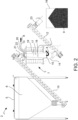
Figure 2 shows a section of the pyrolytic gasifier of the micro-cogenerator according to an embodiment of the present invention. -
Figure 3 shows a section of the assembly comprising the reactor and the hopper of the pyrolytic gasifier according to an embodiment of the present invention. -
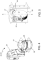
Figure 4 shows a perspective view of a butterfly valve according to an embodiment of the present invention adapted to allow the inflow of the biomass into the reactor of the gasifier shown inFigure 3 and to allow the evacuation of the biochar from said reactor, if necessary. -
Figure 5 shows a detail of the butterfly valve ofFigure 4 when said valve is in the fully open position. -
Figure 6 shows a first view of the assembly consisting of the burner and the Stirling engine according to an embodiment of the present invention. -
Figure 7 shows the section, along the axis A-A shown inFigure 6 , of the assembly consisting of the burner and the Stirling engine according to an embodiment of the present invention. -
Figure 8 shows a detail of the burner shown inFigure 7 . -
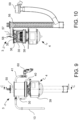
Figure 9 shows a second view of the assembly consisting of the burner and the Stirling engine according to an embodiment of the present invention. -
Figure 10 shows the section, along the axis C-C shown inFigure 9 , of the assembly consisting of the burner and the Stirling engine according to an embodiment of the present invention. - With reference to
Figure 1 , a micro-cogenerator according to an embodiment of the present invention is globally indicated withreference numeral 1. - Said micro-cogenerator 1 comprises a
pyrolytic gasifier 2, aburner 3 and aStirling engine 4. - The
pyrolytic gasifier 2 is shown in more detail inFigure 2 , while theburner 3 and theStirling engine 4 are more visible inFigures 6-10 . - The
gasifier 2 inFigure 2 comprises: - a
storage container 5 of thebiomass 6; - a
reactor 7 inside which thebiomass 6 is gasified generatingcombustible syngas 8 andbiochar 9; - a
loading auger 10 of thebiomass 6 which connects thecontainer 5 to theinlet 11 of thereactor 7; - an unloading auger 12 through which the
biochar 9 is evacuated; - an
outlet duct 13 for thecombustible syngas 8, through which the latter is fed to theburner 3; - a
hopper 14, which connects theoutlet 15 of thereactor 7 to the unloading auger 12 of thebiochar 9, and through which thecombustible syngas 8 is sucked into theduct 13; - a
collection container 16 of thebiochar 9 extracted from thereactor 7. - The
reactor 7 defines areaction chamber 17 and comprises anelectric heater 18 and athermocouple 19. Theelectric heater 18 brings the biomass contained in thereaction chamber 17 to the gasification temperature of, e.g., 900°C, while thethermocouple 19 monitors the temperature in the upper part of thereaction chamber 17 during the gasification process. Theheater 18 and thethermocouple 19, respectively, represent the lower limit and the upper limit of the zone within which thebiomass reaction front 6 must be maintained. - A connecting
element 20, named "buffer", is interposed between theloading auger 10 of thebiomass 6 and theinlet 11 of thereactor 7. Asensor 21 detects the filling level of thebuffer 20, and theloading auger 10 of thebiomass 6 is started whenever saidsensor 21 detects that the filling level of thebuffer 20 is below a predetermined threshold value. - The
biomass 6 under reaction is supported by thebiochar 9 generated during the pyrolytic gasification process seamlessly inside thereaction chamber 17. Advantageously, thepyrolytic gasifier 2 according to the present invention has no support grid for the biomass under reaction which separates it from the spentbiochar 9. Preferably, the unloading auger 12 and thehopper 14 are constantly kept full ofbiochar 9. - The
reactor 7 of thepyrolytic gasifier 2 is shown in greater detail inFigure 3 . - As mentioned above, the
reactor 7 comprises areaction chamber 17 in which thebiomass 6 is gasified in the presence of a given amount of air (sub-stoichiometric). Thereactor 7 further comprises anouter coating 71 to saidreaction chamber 17.Said reaction chamber 17 is truncated-cone in shape and is advantageously made of a polycrystalline alumina fiber-based material, preferably formed under vacuum, comprising at least 70% by weight of polycrystalline alumina and having a density preferably between 350 and 500 kg/m3. For example, said polycrystalline alumina fiber-based material is produced by the company Unifrax under the trade name High Temperature Saffil® Rigiform™, e.g. Saffil® 160 HD. - The
reaction chamber 17 has anupper surface 72 and alower surface 73, wherein the diameter of theupper surface 72 is slightly smaller than the diameter of thelower surface 73 in order to give an adequate draft angle, e.g., about 4°, to the inner surface of thereaction chamber 17. For example, the diameter of theupper surface 72 is comprised between 70 and 90 mm and the diameter of thelower surface 73 is comprised between 100 and 120 mm. Said geometry of thereaction chamber 17 facilitates the downward flow of thebiomass 6. - Said
outer coating 71 has an annular shape and is advantageously made of a microporous insulating material comprising silica. For example, said microporous insulating material is produced by the company Promat under the trade name Promalight®, or by the company Bifire under the trade name Microbifire®, or by the company Unifrax under the trade name Excelfrax®. - Said
outer coating 71 consists of a plurality of overlapping rings 74 made of said microporous insulating material, which guarantee the thermal insulation of thereactor 7. - In the example in
Figure 3 , thereactor 7 further comprises alayer 75 of said polycrystalline alumina fiber-based material having varying thickness interposed between thereaction chamber 17 and theouter coating 71. Preferably, thereaction chamber 17 and thelayer 75 of the polycrystalline alumina fiber-based material form a monolithic structure. According to a specific example, said monolithic structure is sealed on top with the structure by means of arubber gasket 76; on the bottom, instead, given the high working temperature, it is sealed by means of a polycrystalline alumina fiber-basedgasket 77. - The
hopper 14 shown inFigures 2 and3 comprises an upper frame (or edge) 78 adapted to support theouter coating 71 through anappropriate support plate 79, preferably annular. In the example ofFigure 3 , an insulatingplate 80, which is also preferably annular, made, e.g., with biosoluble refractory fibers, is placed above saidsupport plate 79; saidplate 80 ensures the thermal break with thesupport plate 79 and thus with thehopper 14, as well as an airtight seal. Both thehopper 14 and thesupport plate 79 are advantageously made of stainless steel. - Said
hopper 14 further comprises alip 81, which projects below saidframe 78 and defines a support base for thereaction chamber 17 through which thehopper 14 itself receives the producedsyngas 8. Said geometry allows creating an annular volume in the upper part of thehopper 14 through which thesyngas 8 is sucked into theduct 13. - The
syngas feeding duct 13 has a gasket at the interface with thesupport plate 79 consisting of polycrystalline alumina fiber-based rings 82. - The
hopper 14 is advantageously insulated from the unloading auger 12 by means of anelement 83 made of said microporous insulating material. - A
first valve 22 separating the biomass 6 (shown inFigures 2 and3 ) is placed at the inlet interface of thebiomass 6 in thereactor 7, in particular above thebuffer 20. Asecond valve 23 separating the biochar 9 (shown inFigure 2 ) is positioned at the outlet interface of thebiochar 9 from the unloading auger 12. - The
separation valve 22 of thebiomass 6 is opened at the process start-up and allows the inflow ofbiomass 6 and air into thereactor 7. The air supply, although limited, is necessary to support the gasification process by providing heat through the combustion of a small portion of thebiomass 6 and the producedsyngas 8. - The
separation valve 23 of thebiochar 9 is opened whenever it is necessary to expel thebiochar 9, thus operating discontinuously. - Said
separation valves Figures 4 and 5 . Thevalve Figure 4 is in the fully closed position, while thevalve Figure 5 is in the fully open position. - The
valve Figure 4 comprises anactuator 24, acylindrical valve body 25, a plate-like shutter 26 and aninsert 27 shaped as an arc of circumference. - When said
valve Figure 5 ), the plate-like shutter 26 assumes a position parallel to the longitudinal axis X-X of thecylindrical valve body 25 and theinsert 27 adheres to aportion 28 of the edge of theshutter 26 which would otherwise come into contact with thebiomass 6 or with thebiochar 9. In this manner, the gap between thevalve body 25 and theshutter 26 is filled along the longitudinal axis X-X of thevalve body 25, preventing thebiomass 6 and thebiochar 9 from settling on the edge of theshutter 26, clogging thevalve - In light of the aforesaid description, it is apparent that the
gasifier 2 is of the "downdraft" (i.e., thebiomass 6 flows downward and thesyngas 8 produced transits in the same direction) "open core" (i.e., with air supply from above along with the biomass) type. - As mentioned above,
Figures 6-10 illustrate the assembly consisting of theburner 3 and theStirling engine 4. - The
burner 3 comprises: - a
combustion chamber 30 in which thefuel syngas 8 coming from thegasifier 2 is burned in the presence ofcombustion air 31 generatinghot combustion gases 32; - an
exhaust system 33, fixed on top of thecombustion chamber 30, which receives the exhaust fumes 34 exiting theStirling engine 4, as further described below; -
pre-mixing flanges 35 for thefuel syngas 8 and thecombustion air 31; - a nozzle or
duct 36, preferably ceramic, downstream of thepre-mixing flanges 35, which conveys thefuel syngas 8 and thecombustion air 31 into thecombustion chamber 30. The mixture offuel syngas 8 andcombustion air 31 exiting the nozzle orduct 36 is indicated with thereference numeral 37 inFigure 8 . - Furthermore, the
pre-mixing flanges 35 allow partial cooling of thefuel syngas 8 by means of thecombustion air 31. - The
Stirling engine 4 comprises a high-temperature heat exchanger 38 (so-called "hot exchanger") shown inFigures 7, 8 ,10 , a low-temperature heat exchanger (so-called "cold exchanger"), a regenerator and anelectric generator 39. The cold exchanger and the regenerator are not visible in the figures. Thehot exchanger 38 of the Stirling engine is inserted inside thecombustion chamber 30. - Downstream of the
hot exchanger 38 of the Stirling engine, atubular element 40 is placed, also indicated as a cooling ring, inside which a cooling fluid flows, so that heat transfer downstream of saidhot exchanger 38 is prevented. In other words, the coolingring 40 performs the thermal break function between theburner 3 and theStirling engine 4, preventing unwanted heat from entering the part of theStirling engine 4 under thehot exchanger 38 and safeguarding the underlying components from excessive heating. - The
combustion chamber 30 of theburner 3 consists of a cylinder which integrates connections for the feedingduct 13 of thefuel syngas 8 coming from thegasifier 2 and for the feedingduct 41 of thecombustion air 31. Furthermore, thecombustion chamber 30 integrates theattachment flange 42 to theStirling engine 4 and theattachment flange 43 to theexhaust system 33. - A
bell 44 and anelement 45 made of porous ceramic material (porous ceramic means 45) are placed inside thecombustion chamber 30 of theburner 3. - Said
bell 44 is open at the bottom and houses thehot exchanger 38 of the Stirling engine inside. In particular, saidhot exchanger 38 is inserted from the open bottom of thebell 44. Saidbell 44 is such to convey thehot combustion gases 32 into thehot exchanger 38, where they undergo heat exchange providing heat and generating exhaust fumes 34 (or combustion fumes 34). In other words, saidbell 44 constrains thehot combustion gases 32 to flow through the entirehot exchanger 38 with minimal heat dissipation to the outside, thus optimizing the heat exchange with theStirling engine 4. - Said
bell 44 comprises steel walls internally lined with a refractory insulating material, preferably a material based on polycrystalline alumina fiber. For example, said material comprises at least 70% by weight of polycrystalline alumina, preferably at least 75% by weight, more preferably at least 80% by weight, such as about 90% by weight. Preferably, said material further comprises at least 5% by weight of silica, preferably between 10% and 30% by weight of silica, more preferably between 10% and 25% by weight of silica, even more preferably between 10% and 20% by weight of silica. For example, said polycrystalline alumina fiber-based material is produced by the company Schupp under the trade name ITM-Fibermax®, preferably Blanket 1600-130. - The aforementioned nozzle or
duct 36 may be replaced by a hole made in said refractory insulating material, such as to convey thefuel syngas 8 and thecombustion air 31 inside thecombustion chamber 30. - There is a
gap 46 between saidbell 44 and saidcombustion chamber 30 which is traveled upward by the exhaust fumes 34 exiting thehot exchanger 38, as evident fromFigure 8 . - The porous ceramic means 45 is housed in the upper part of the
bell 44 above thehot exchanger 38 and is supported at least partially by the refractory insulating material of thebell 44. Said porous ceramic means 45 is an optimized combustion volume in which thesyngas 8 is combusted in the presence ofcombustion air 31 generating hot combustion gases 32 (Figure 8 ). Furthermore, the porous means 45 allows a homogeneous temperature distribution, ensuring optimal heat exchange with theStirling engine 4 and low polluting emissions. - According to an embodiment, the porous material with which said means 45 is made comprises silicon carbide, alumina and silica and is, for example, produced by the company Lanik under the trade name Vukopor® S.
- According to another embodiment, said porous ceramic material comprises alumina, silica, zirconia and magnesium oxide. Preferably, said porous ceramic material is produced by the company Lanik under the trade name Vukopor® HT.
- In the example of
Figures 7 and 8 , thebell 44 comprises anadditional element 47 made of refractory insulating material, e.g., based on polycrystalline alumina fiber, immediately below the porous ceramic means 45, such as to prevent unwanted entry of heat through the top of the Stirling engine below. Saidelement 47 mimics the shape of the upper dome of thehot exchanger 38 of the Stirling engine, visible inFigures 7, 8 ,10 . - The
exhaust system 33 mentioned above receives the combustion fumes 34 exiting thehot exchanger 38 of theStirling engine 4, once the latter have traveled upward through thegap 46 present between thecombustion chamber 30 and thebell 44. - Said
exhaust system 33 comprises anexhaust 55 from which combustion fumes 34 escape, aheat exchanger 56 connected to saidexhaust 55 for recovering heat from the exhaust fumes 34 (Figure 10 ), alambda probe 57 which provides a signal based on which the air-syngas ratio at the inlet ofburner 3 is adjusted (Figures 6 ,10 ), and athermocouple 58 which measures the temperature of the combustion fumes 34 (Figures 6 ,10 ). - An extraction fan 59 (shown in
Figures 6 and10 ) of the combustion fumes 34 is connected to saidheat exchanger 56, by virtue of which thecombustible syngas 8 from thegasifier 2 and thecombustion air 31 are sucked inside thecombustion chamber 30. Saidextraction fan 59 has variable speed. - To obviate the fact that the pyrolytic gasifier and the Stirling engine, by their nature, have rather slow start-up and control reaction times, the micro-cogenerator 1 can advantageously be coupled to electrical energy storage systems (batteries) and thermal energy accumulation systems (puffers). The remaining capacity is measured for both accumulations so that micro-cogenerator 1 will only turn on if a minimum operating time necessary for heat regulation of all syngas ducts is guaranteed. In particular, a temperature probe is used for the puffer, and a voltage probe is used for the batteries. For the batteries, there is the possibility of both voltage reading and SoC ("state of charge") reading from the Bus and input of a digital request signal.
- The
micro-generator 1 is equipped with an electronic control, which manages the operation of the machine through the installed sensors and actuators and is independently powered by on-board batteries so that it can be safely shut down even in case the external electrical connection is interrupted. To be able to start up, the micro-generator 1 checks for the presence of the external power grid (both "on-grid" and "off-grid" via inverter). - The process of cogeneration of electrical energy and heat within the micro-cogenerator 1 starting from the
biomass 6 is described below with reference to the figures. - The pyrolytic gasification process is started by means of the
electric heater 18, which brings thebiomass 6 to the gasification temperature, e.g., about 900°C. During the start-up phase of the process, theseparation valve 22 of thebiomass 6 is opened. During the start-up phase of the process, theextraction fan 59 is activated with a speed proportional to the temperature of theelectric heater 18. - The
biomass 6 is fed into thereactor 7 of thepyrolytic gasifier 2, through theinlet 11, by means of theloading auger 10. When the filling level of thebuffer 20 is under a given threshold, thebiomass loading auger 10 is started; when the filling level of thebuffer 20 is above said threshold, thebiomass loading auger 10 is stopped and the feeding of thebiomass 6 to the reactor is interrupted. - Once the gasification has been started and the
biochar 9 has accumulated in thereactor 7, the reaction front advances from the bottom to the top wherebiomass 6 not yet gasified is located. - The
reaction chamber 17 is maintained at a suitable gasification temperature at which the biomass reacts generating syngas and biochar, preferably comprised between 1000°C and 1200°C in order to maximize the syngas production. - The
thermocouple 19 keeps the temperature of the upper part of thereaction chamber 17 monitored; when the integral over time of the temperature measured bythermocouple 19 exceeds a given threshold value of said integral, theseparation valve 23 of thebiochar 9 is opened, the unloading auger 12 is started and part of thebiochar 9 is extracted. In this manner, the reactingbiomass 6 is made to flow downward and along with it the reaction front as well, which remains confined to the reaction zone delimited between thethermocouple 19 and theelectric heater 18. - The
gasifier 2, once fully operational, works with a slow and intermittent flow ofbiomass 6 such as to maintain the reaction front within the aforementioned reaction zone. - The produced
fuel syngas 8, before flowing out of thegasifier 2 through theduct 13, crosses a layer ofbiochar 9, which is still warm and ensures a good abatement of dust and tar. - During the step of shutting down the process, a small amount of
biochar 9 is extracted to ensure that thebiomass 6 is in a sufficiently low and safe zone of the reaction chamber, and thebiomass separation valve 22 is closed to prevent air from entering thereactor 7 and fumes from escaping. - By operating the
extraction fan 59, the system consisting of thegasifier 2 and theburner 3 is depressurized and the inflows offuel syngas 8 from thegasifier 2 to theburner 3 and of air to both thegasifier 2 and theburner 3 are adjusted. - By operating the
extraction fan 59, the combustion fumes 34 are extracted which travel upward through thegap 46 between thecombustion chamber 30 and thebell 44, creating a vacuum inside theburner 3. In turn, thefuel syngas 8 exiting thegasifier 2 and thecombustion air 31 are sucked into thecombustion chamber 30 of the burner, respectively, through thesupply ducts gasifier 2. - Once the presence of
fuel syngas 8 is detected inside theburner 3, the latter is ignited and an increasing amount ofcombustion air 31 is supplied by acting on theair valve 60 located on theduct 41. - The
fuel syngas 8 and thecombustion air 31 are sucked inside thecombustion chamber 30 passing through thepre-mixing flanges 35, then the nozzle orduct 36, until they arrive inside the porous ceramic means 45, which defines the volume in which the combustion takes place with the generation of thehot combustion gases 32. - The
hot combustion gases 32 are subjected to heat exchange within thehot exchanger 38 of theStirling engine 4, from which heat is recovered that puts theelectric generator 39 in oscillation, thus obtaining the aforementioned combustion fumes 34 resulting from said heat exchange. - The combustion fumes 34 are extracted through the
extraction fan 59. Said combustion fumes 34 travel upward through thegap 46 present between thecombustion chamber 30 and thebell 44, pass through theexhaust 55 on which thelambda probe 57 and thethermocouple 58 are placed, then they are fed to theheat exchanger 56 for recovery of the heat contained therein. Thelambda probe 57 provides a signal based on which the air-syngas ratio is adjusted accurately by virtue of thevalve 60 located on theinlet duct 41 of thecombustion air 31, adjusting the pressure drop and thus the inflow. - It is apparent that only one particular embodiment of the present invention was described. Those skilled in the art will be able to make all the necessary modifications to the
micro-cogenerator 1 for the adaptation thereof to particular conditions, without however departing from the scope of protection as defined in the appended claims.
Claims (9)
- A micro-cogenerator (1) comprising:a pyrolytic gasifier (2) adapted to produce syngas (8) and biochar (9) from a renewable and sustainable energy source (6), preferably woody biomass,a burner (3) adapted to receive the syngas (8) produced by said pyrolytic gasifier (2) and to generate hot combustion gases (32),a Stirling engine (4) comprising a heat exchanger (38) fed with said hot combustion gases (32), said Stirling engine (4) being adapted to generate electric energy,wherein said pyrolytic gasifier (2) comprises a reaction chamber (17) inside which said energy source (6) is gasified in the presence of air, thus generating syngas (8) and biochar (9),characterized in that said reaction chamber (17) has truncated-cone shape and is made of a polycrystalline alumina fiber-based material comprising at least 70% by weight of polycrystalline alumina and, optionally, at least 5% by weight of silica, said material having a density preferably between 350 and 500 kg/m3,said micro-cogenerator comprising an exhaust system (33) adapted to receive exhaust fumes (34) leaving the heat exchanger (38) of the Stirling engine (4),wherein said exhaust system (33) comprises an exchanger (56) for the recovery of heat from said exhaust fumes (34), a lambda probe (57) which provides a signal based on which the ratio of air (31) to syngas (8) at the burner (3) inlet is adjusted, and a thermocouple (58) which measures the temperature of said exhaust fumes (34),said micro-cogenerator further comprising an extraction fan (59) connected to said exchanger (56) for the recovery of heat from the exhaust fumes (34), said extraction fan (59) is configured to extract the exhaust fumes (34) thus creating a vacuum inside the burner (3) and the pyrolytic gasifier (2) and, in turn, to adjust the inflow of the syngas (8) from the pyrolytic gasifier (2) to the burner (3) and the inflows of air into both the pyrolytic gasifier (2) and the burner (3).
- A micro-cogenerator (1) according to claim 1, wherein said polycrystalline alumina fiber-based material comprises at least 75% by weight of polycrystalline alumina, preferably at least 80% by weight, more preferably about 90% by weight, and an amount of silica of at least 5% by weight, preferably between 10% and 30% by weight, more preferably between 10% and 25% by weight, even more preferably between 10% and 20% by weight.
- A micro-cogenerator (1) according to claim 1 or 2, wherein said pyrolytic gasifier (2) comprises an outer coating (71) with respect to said reaction chamber (17), said outer coating (71) having an annular shape and being preferably made of a microporous insulating material comprising silica.
- A micro-cogenerator (1) according to claim 3, wherein said pyrolytic gasifier (2) comprises a layer (75) of said polycrystalline alumina fiber-based material having variable thickness interposed between said reaction chamber (17) and said outer coating (71), preferably said reaction chamber (17) and said layer (75) of polycrystalline alumina fiber-based material forming a monolithic structure.
- A micro-cogenerator (1) according to any one of the preceding claims, said truncated-cone reaction chamber (17) having an upper surface (72) and a lower surface (73), wherein the diameter of the upper surface (72) is smaller than the diameter of the lower surface (73), said diameters being such as to give the inner surface of the truncated-cone reaction chamber a draft angle comprised between 2° and 15°, preferably of about 4°.
- A micro-cogenerator (1) according to any one of the preceding claims, wherein said pyrolytic gasifier (2) comprises:an unloading auger (12) for the evacuation of the biochar (9),a hopper (14) connecting the reaction chamber and the unloading auger (12), said hopper (14) forming a collection volume of the syngas (8) produced in the reaction chamber, anda connection duct (13) between said hopper (14) and the burner (3), from which the syngas (8) is sucked and fed to said burner (3),wherein said hopper (14) comprises an upper frame (78) adapted to support said outer coating (71), preferably through a suitable support plate (79), and a lip (81) projecting below said frame (78) and defining a support base for said reaction chamber (17) through which the hopper (14) receives the syngas (8) produced.
- A micro-cogenerator (1) according to any one of the preceding claims, wherein said reaction chamber (17) comprises an electric heater (18) adapted to heat the reaction chamber (17) to the gasification temperature, and a thermocouple (19) adapted to monitor the temperature in the upper part of the reaction chamber (17),
wherein the reaction front is comprised between said heater (18) and said thermocouple (19). - A micro-cogenerator (1) according to any one of the preceding claims, wherein the energy source (6) under reaction is supported by the biochar (9) produced during the gasification of said energy source (6), said micro-cogenerator (1) not comprising any support grid for said energy source (6).
- A micro-cogenerator (1) according to any one of the preceding claims, wherein said pyrolytic gasifier (2) comprises a first butterfly valve (22) at the input interface of the energy source (6) in the reaction chamber such as to allow the inflow of the energy source (6) into the reaction chamber (17), and/or a second butterfly valve (23) at the output interface of the biochar (9) from the unloading auger (12) such as to allow the evacuation of the biochar (9) from the reaction chamber (17) if required, said butterfly valves (22, 23) comprising a cylindrical valve body (25), a plate shutter (26), and an insert (27) having the shape of an arc of circumference,when said valve (22, 23) is in the fully open position, the shutter (26) takes a position parallel to the longitudinal axis (X-X) of the cylindrical valve body (25),said insert (27) adhering to a portion (28) of the edge of the shutter (26) when the valve (22, 23) is in the fully open position, thus filling the space between the valve body (25) and the shutter (26) along the longitudinal axis (X-X) of the cylindrical valve body (25) and preventing the energy source (6) or the biochar (9) from depositing on the edge of the shutter (26).
Applications Claiming Priority (2)
| Application Number | Priority Date | Filing Date | Title |
|---|---|---|---|
| IT102021000016688A IT202100016688A1 (en) | 2021-06-25 | 2021-06-25 | MICRO-COGENERATOR |
| PCT/IB2022/055876 WO2022269555A1 (en) | 2021-06-25 | 2022-06-24 | Micro-cogenerator |
Publications (3)
| Publication Number | Publication Date |
|---|---|
| EP4359654A1 EP4359654A1 (en) | 2024-05-01 |
| EP4359654B1 true EP4359654B1 (en) | 2025-03-19 |
| EP4359654C0 EP4359654C0 (en) | 2025-03-19 |
Family
ID=77989876
Family Applications (1)
| Application Number | Title | Priority Date | Filing Date |
|---|---|---|---|
| EP22741849.8A Active EP4359654B1 (en) | 2021-06-25 | 2022-06-24 | Micro-cogenerator |
Country Status (3)
| Country | Link |
|---|---|
| EP (1) | EP4359654B1 (en) |
| IT (1) | IT202100016688A1 (en) |
| WO (1) | WO2022269555A1 (en) |
Citations (6)
| Publication number | Priority date | Publication date | Assignee | Title |
|---|---|---|---|---|
| ITFI20000150A1 (en) * | 2000-07-03 | 2002-01-03 | Edelberto Pagliai | APPLICATION OF THE ENDOTHERMAL GASIFICATION PROCESS ON LIQUID FUELS THROUGH H2O AND / OR H2O2 FOR THE REALIZATION OF COMBUSTIBLE GAS |
| US20090078176A1 (en) * | 2006-01-11 | 2009-03-26 | Eckhart Weber | Wood-Pellet Cogeneration Unit With Stirling Engine in Condensing Technology |
| CN208382164U (en) * | 2017-08-29 | 2019-01-15 | 西安美润环保工程技术有限公司 | The rotary superconduction waste cracking furnace of bicone |
| CN109424963A (en) * | 2017-08-29 | 2019-03-05 | 西安美润环保工程技术有限公司 | The rotary superconduction waste cracking furnace of bicone |
| CN111690436A (en) * | 2019-03-14 | 2020-09-22 | 陕西博瑞新环保科技有限公司 | High-efficiency safety garbage cracking gasification furnace |
| WO2021004658A1 (en) * | 2019-07-09 | 2021-01-14 | Cmd Costruzioni Motori Diesel | An improved reactor for the gasification of wood-cellulose residual materials |
Family Cites Families (3)
| Publication number | Priority date | Publication date | Assignee | Title |
|---|---|---|---|---|
| US7906695B2 (en) * | 2004-10-25 | 2011-03-15 | Res/Op Technologies Inc. | Biomass conversion by combustion |
| ITMO20130235A1 (en) * | 2013-08-08 | 2015-02-09 | Marco Errani | PLANT FOR THE PRODUCTION OF ENERGY BY GASIFICATION. |
| CN109424964A (en) * | 2017-08-29 | 2019-03-05 | 西安美润环保工程技术有限公司 | The horizontal rotary superconduction garbage cracking gasification furnace of bimetallic tube |
-
2021
- 2021-06-25 IT IT102021000016688A patent/IT202100016688A1/en unknown
-
2022
- 2022-06-24 EP EP22741849.8A patent/EP4359654B1/en active Active
- 2022-06-24 WO PCT/IB2022/055876 patent/WO2022269555A1/en not_active Ceased
Patent Citations (6)
| Publication number | Priority date | Publication date | Assignee | Title |
|---|---|---|---|---|
| ITFI20000150A1 (en) * | 2000-07-03 | 2002-01-03 | Edelberto Pagliai | APPLICATION OF THE ENDOTHERMAL GASIFICATION PROCESS ON LIQUID FUELS THROUGH H2O AND / OR H2O2 FOR THE REALIZATION OF COMBUSTIBLE GAS |
| US20090078176A1 (en) * | 2006-01-11 | 2009-03-26 | Eckhart Weber | Wood-Pellet Cogeneration Unit With Stirling Engine in Condensing Technology |
| CN208382164U (en) * | 2017-08-29 | 2019-01-15 | 西安美润环保工程技术有限公司 | The rotary superconduction waste cracking furnace of bicone |
| CN109424963A (en) * | 2017-08-29 | 2019-03-05 | 西安美润环保工程技术有限公司 | The rotary superconduction waste cracking furnace of bicone |
| CN111690436A (en) * | 2019-03-14 | 2020-09-22 | 陕西博瑞新环保科技有限公司 | High-efficiency safety garbage cracking gasification furnace |
| WO2021004658A1 (en) * | 2019-07-09 | 2021-01-14 | Cmd Costruzioni Motori Diesel | An improved reactor for the gasification of wood-cellulose residual materials |
Also Published As
| Publication number | Publication date |
|---|---|
| IT202100016688A1 (en) | 2022-12-25 |
| EP4359654A1 (en) | 2024-05-01 |
| EP4359654C0 (en) | 2025-03-19 |
| WO2022269555A1 (en) | 2022-12-29 |
Similar Documents
| Publication | Publication Date | Title |
|---|---|---|
| US4840129A (en) | Pyrolysis system | |
| JP5120823B1 (en) | Waste gasification melting furnace | |
| WO1999031202A1 (en) | Fuel gasifying system | |
| JP5610561B2 (en) | Tar decomposition method and tar decomposition apparatus | |
| KR100794914B1 (en) | Coal gasification method and apparatus in IGCC system | |
| JP6759492B2 (en) | Carbide production equipment, carbide production methods, and carbide production systems | |
| KR101921225B1 (en) | Waste material melting furnace | |
| KR101689917B1 (en) | Gasification cooling system having seal | |
| JP2012001649A (en) | Method for regenerating filter, and gasification power generation plant using the same | |
| EP4359654B1 (en) | Micro-cogenerator | |
| JP2008063363A (en) | Gasification furnace and gasification furnace system | |
| EP4359653B1 (en) | Cogeneration process and related apparatus | |
| JP6170579B1 (en) | Biomass power generation system and pyrolysis furnace return system | |
| JP2004144403A (en) | Gasification molten waste treatment equipment | |
| CN101845327B (en) | Waste gasification purification reacting furnace | |
| CN113310055A (en) | Thermal cracking gasification system for storing domestic garbage | |
| JP2020105451A (en) | Gasification furnace using biomass raw material | |
| JP7118341B2 (en) | Hydrogen production equipment | |
| ITMI20110045A1 (en) | MULTI-PURPOSE THERMOVALORIZATION PLANT OF BIOLOGICAL SLUDGE ORGANIC WASTE AND BIOMASS MINUTES | |
| JP4993460B2 (en) | Method for thermal decomposition of carbonaceous raw materials | |
| CN108929721B (en) | Three layers of the center air guide fixed bed inverting tar gasification furnace of gas supply | |
| CN118421343A (en) | Internal heating cigar type pyrolysis carbonization system and method | |
| CN115127108A (en) | Biomass pyrolysis pressure stabilizing system and method thereof | |
| CN112728553A (en) | Garbage disposal device | |
| WO2019138339A1 (en) | Biomass pyrogasification plant |
Legal Events
| Date | Code | Title | Description |
|---|---|---|---|
| STAA | Information on the status of an ep patent application or granted ep patent |
Free format text: STATUS: UNKNOWN |
|
| STAA | Information on the status of an ep patent application or granted ep patent |
Free format text: STATUS: THE INTERNATIONAL PUBLICATION HAS BEEN MADE |
|
| PUAI | Public reference made under article 153(3) epc to a published international application that has entered the european phase |
Free format text: ORIGINAL CODE: 0009012 |
|
| STAA | Information on the status of an ep patent application or granted ep patent |
Free format text: STATUS: REQUEST FOR EXAMINATION WAS MADE |
|
| 17P | Request for examination filed |
Effective date: 20231220 |
|
| AK | Designated contracting states |
Kind code of ref document: A1 Designated state(s): AL AT BE BG CH CY CZ DE DK EE ES FI FR GB GR HR HU IE IS IT LI LT LU LV MC MK MT NL NO PL PT RO RS SE SI SK SM TR |
|
| DAV | Request for validation of the european patent (deleted) | ||
| DAX | Request for extension of the european patent (deleted) | ||
| GRAP | Despatch of communication of intention to grant a patent |
Free format text: ORIGINAL CODE: EPIDOSNIGR1 |
|
| STAA | Information on the status of an ep patent application or granted ep patent |
Free format text: STATUS: GRANT OF PATENT IS INTENDED |
|
| INTG | Intention to grant announced |
Effective date: 20241014 |
|
| GRAS | Grant fee paid |
Free format text: ORIGINAL CODE: EPIDOSNIGR3 |
|
| GRAA | (expected) grant |
Free format text: ORIGINAL CODE: 0009210 |
|
| STAA | Information on the status of an ep patent application or granted ep patent |
Free format text: STATUS: THE PATENT HAS BEEN GRANTED |
|
| AK | Designated contracting states |
Kind code of ref document: B1 Designated state(s): AL AT BE BG CH CY CZ DE DK EE ES FI FR GB GR HR HU IE IS IT LI LT LU LV MC MK MT NL NO PL PT RO RS SE SI SK SM TR |
|
| REG | Reference to a national code |
Ref country code: GB Ref legal event code: FG4D |
|
| REG | Reference to a national code |
Ref country code: CH Ref legal event code: EP |
|
| REG | Reference to a national code |
Ref country code: DE Ref legal event code: R096 Ref document number: 602022012033 Country of ref document: DE |
|
| REG | Reference to a national code |
Ref country code: IE Ref legal event code: FG4D |
|
| U01 | Request for unitary effect filed |
Effective date: 20250414 |
|
| U07 | Unitary effect registered |
Designated state(s): AT BE BG DE DK EE FI FR IT LT LU LV MT NL PT RO SE SI Effective date: 20250422 |
|
| U20 | Renewal fee for the european patent with unitary effect paid |
Year of fee payment: 4 Effective date: 20250523 |
|
| PG25 | Lapsed in a contracting state [announced via postgrant information from national office to epo] |
Ref country code: RS Free format text: LAPSE BECAUSE OF FAILURE TO SUBMIT A TRANSLATION OF THE DESCRIPTION OR TO PAY THE FEE WITHIN THE PRESCRIBED TIME-LIMIT Effective date: 20250619 |
|
| PG25 | Lapsed in a contracting state [announced via postgrant information from national office to epo] |
Ref country code: NO Free format text: LAPSE BECAUSE OF FAILURE TO SUBMIT A TRANSLATION OF THE DESCRIPTION OR TO PAY THE FEE WITHIN THE PRESCRIBED TIME-LIMIT Effective date: 20250619 |
|
| PG25 | Lapsed in a contracting state [announced via postgrant information from national office to epo] |
Ref country code: HR Free format text: LAPSE BECAUSE OF FAILURE TO SUBMIT A TRANSLATION OF THE DESCRIPTION OR TO PAY THE FEE WITHIN THE PRESCRIBED TIME-LIMIT Effective date: 20250319 |
|
| PG25 | Lapsed in a contracting state [announced via postgrant information from national office to epo] |
Ref country code: GR Free format text: LAPSE BECAUSE OF FAILURE TO SUBMIT A TRANSLATION OF THE DESCRIPTION OR TO PAY THE FEE WITHIN THE PRESCRIBED TIME-LIMIT Effective date: 20250620 |
|
| PG25 | Lapsed in a contracting state [announced via postgrant information from national office to epo] |
Ref country code: SM Free format text: LAPSE BECAUSE OF FAILURE TO SUBMIT A TRANSLATION OF THE DESCRIPTION OR TO PAY THE FEE WITHIN THE PRESCRIBED TIME-LIMIT Effective date: 20250319 |
|
| PG25 | Lapsed in a contracting state [announced via postgrant information from national office to epo] |
Ref country code: ES Free format text: LAPSE BECAUSE OF FAILURE TO SUBMIT A TRANSLATION OF THE DESCRIPTION OR TO PAY THE FEE WITHIN THE PRESCRIBED TIME-LIMIT Effective date: 20250319 |
|
| PG25 | Lapsed in a contracting state [announced via postgrant information from national office to epo] |
Ref country code: PL Free format text: LAPSE BECAUSE OF FAILURE TO SUBMIT A TRANSLATION OF THE DESCRIPTION OR TO PAY THE FEE WITHIN THE PRESCRIBED TIME-LIMIT Effective date: 20250319 |
|
| PG25 | Lapsed in a contracting state [announced via postgrant information from national office to epo] |
Ref country code: CZ Free format text: LAPSE BECAUSE OF FAILURE TO SUBMIT A TRANSLATION OF THE DESCRIPTION OR TO PAY THE FEE WITHIN THE PRESCRIBED TIME-LIMIT Effective date: 20250319 |
|
| PG25 | Lapsed in a contracting state [announced via postgrant information from national office to epo] |
Ref country code: SK Free format text: LAPSE BECAUSE OF FAILURE TO SUBMIT A TRANSLATION OF THE DESCRIPTION OR TO PAY THE FEE WITHIN THE PRESCRIBED TIME-LIMIT Effective date: 20250319 |
|
| PG25 | Lapsed in a contracting state [announced via postgrant information from national office to epo] |
Ref country code: IS Free format text: LAPSE BECAUSE OF FAILURE TO SUBMIT A TRANSLATION OF THE DESCRIPTION OR TO PAY THE FEE WITHIN THE PRESCRIBED TIME-LIMIT Effective date: 20250719 |
|
| PLBE | No opposition filed within time limit |
Free format text: ORIGINAL CODE: 0009261 |
|
| STAA | Information on the status of an ep patent application or granted ep patent |
Free format text: STATUS: NO OPPOSITION FILED WITHIN TIME LIMIT |
|
| REG | Reference to a national code |
Ref country code: CH Ref legal event code: H13 Free format text: ST27 STATUS EVENT CODE: U-0-0-H10-H13 (AS PROVIDED BY THE NATIONAL OFFICE) Effective date: 20260127 |
|
| REG | Reference to a national code |
Ref country code: CH Ref legal event code: L10 Free format text: ST27 STATUS EVENT CODE: U-0-0-L10-L00 (AS PROVIDED BY THE NATIONAL OFFICE) Effective date: 20260128 |
|
| PG25 | Lapsed in a contracting state [announced via postgrant information from national office to epo] |
Ref country code: MC Free format text: LAPSE BECAUSE OF FAILURE TO SUBMIT A TRANSLATION OF THE DESCRIPTION OR TO PAY THE FEE WITHIN THE PRESCRIBED TIME-LIMIT Effective date: 20250319 |
|
| 26N | No opposition filed |
Effective date: 20251222 |
|
| PG25 | Lapsed in a contracting state [announced via postgrant information from national office to epo] |
Ref country code: IE Free format text: LAPSE BECAUSE OF NON-PAYMENT OF DUE FEES Effective date: 20250624 |
|
| PG25 | Lapsed in a contracting state [announced via postgrant information from national office to epo] |
Ref country code: CH Free format text: LAPSE BECAUSE OF NON-PAYMENT OF DUE FEES Effective date: 20250630 |