EP4358499A1 - Electronic device comprising structure for preventing damage to display - Google Patents
Electronic device comprising structure for preventing damage to display Download PDFInfo
- Publication number
- EP4358499A1 EP4358499A1 EP23748686.5A EP23748686A EP4358499A1 EP 4358499 A1 EP4358499 A1 EP 4358499A1 EP 23748686 A EP23748686 A EP 23748686A EP 4358499 A1 EP4358499 A1 EP 4358499A1
- Authority
- EP
- European Patent Office
- Prior art keywords
- region
- coil
- housing
- electronic device
- temperature
- Prior art date
- Legal status (The legal status is an assumption and is not a legal conclusion. Google has not performed a legal analysis and makes no representation as to the accuracy of the status listed.)
- Pending
Links
Images










Classifications
-
- G—PHYSICS
- G06—COMPUTING OR CALCULATING; COUNTING
- G06F—ELECTRIC DIGITAL DATA PROCESSING
- G06F1/00—Details not covered by groups G06F3/00 - G06F13/00 and G06F21/00
- G06F1/16—Constructional details or arrangements
- G06F1/1613—Constructional details or arrangements for portable computers
- G06F1/1633—Constructional details or arrangements of portable computers not specific to the type of enclosures covered by groups G06F1/1615 - G06F1/1626
- G06F1/1637—Details related to the display arrangement, including those related to the mounting of the display in the housing
- G06F1/1652—Details related to the display arrangement, including those related to the mounting of the display in the housing the display being flexible, e.g. mimicking a sheet of paper, or rollable
-
- G—PHYSICS
- G06—COMPUTING OR CALCULATING; COUNTING
- G06F—ELECTRIC DIGITAL DATA PROCESSING
- G06F1/00—Details not covered by groups G06F3/00 - G06F13/00 and G06F21/00
- G06F1/16—Constructional details or arrangements
- G06F1/1613—Constructional details or arrangements for portable computers
- G06F1/1615—Constructional details or arrangements for portable computers with several enclosures having relative motions, each enclosure supporting at least one I/O or computing function
- G06F1/1624—Constructional details or arrangements for portable computers with several enclosures having relative motions, each enclosure supporting at least one I/O or computing function with sliding enclosures, e.g. sliding keyboard or display
-
- G—PHYSICS
- G06—COMPUTING OR CALCULATING; COUNTING
- G06F—ELECTRIC DIGITAL DATA PROCESSING
- G06F1/00—Details not covered by groups G06F3/00 - G06F13/00 and G06F21/00
- G06F1/16—Constructional details or arrangements
- G06F1/1613—Constructional details or arrangements for portable computers
- G06F1/1633—Constructional details or arrangements of portable computers not specific to the type of enclosures covered by groups G06F1/1615 - G06F1/1626
- G06F1/1656—Details related to functional adaptations of the enclosure, e.g. to provide protection against EMI, shock, water, or to host detachable peripherals like a mouse or removable expansions units like PCMCIA cards, or to provide access to internal components for maintenance or to removable storage supports like CDs or DVDs, or to mechanically mount accessories
-
- G—PHYSICS
- G06—COMPUTING OR CALCULATING; COUNTING
- G06F—ELECTRIC DIGITAL DATA PROCESSING
- G06F1/00—Details not covered by groups G06F3/00 - G06F13/00 and G06F21/00
- G06F1/16—Constructional details or arrangements
- G06F1/1613—Constructional details or arrangements for portable computers
- G06F1/1633—Constructional details or arrangements of portable computers not specific to the type of enclosures covered by groups G06F1/1615 - G06F1/1626
- G06F1/1675—Miscellaneous details related to the relative movement between the different enclosures or enclosure parts
- G06F1/1677—Miscellaneous details related to the relative movement between the different enclosures or enclosure parts for detecting open or closed state or particular intermediate positions assumed by movable parts of the enclosure, e.g. detection of display lid position with respect to main body in a laptop, detection of opening of the cover of battery compartment
-
- G—PHYSICS
- G06—COMPUTING OR CALCULATING; COUNTING
- G06F—ELECTRIC DIGITAL DATA PROCESSING
- G06F1/00—Details not covered by groups G06F3/00 - G06F13/00 and G06F21/00
- G06F1/16—Constructional details or arrangements
- G06F1/1613—Constructional details or arrangements for portable computers
- G06F1/1633—Constructional details or arrangements of portable computers not specific to the type of enclosures covered by groups G06F1/1615 - G06F1/1626
- G06F1/1675—Miscellaneous details related to the relative movement between the different enclosures or enclosure parts
- G06F1/1681—Details related solely to hinges
-
- G—PHYSICS
- G06—COMPUTING OR CALCULATING; COUNTING
- G06F—ELECTRIC DIGITAL DATA PROCESSING
- G06F1/00—Details not covered by groups G06F3/00 - G06F13/00 and G06F21/00
- G06F1/16—Constructional details or arrangements
- G06F1/1613—Constructional details or arrangements for portable computers
- G06F1/1633—Constructional details or arrangements of portable computers not specific to the type of enclosures covered by groups G06F1/1615 - G06F1/1626
- G06F1/1675—Miscellaneous details related to the relative movement between the different enclosures or enclosure parts
- G06F1/1683—Miscellaneous details related to the relative movement between the different enclosures or enclosure parts for the transmission of signal or power between the different housings, e.g. details of wired or wireless communication, passage of cabling
-
- G—PHYSICS
- G06—COMPUTING OR CALCULATING; COUNTING
- G06F—ELECTRIC DIGITAL DATA PROCESSING
- G06F1/00—Details not covered by groups G06F3/00 - G06F13/00 and G06F21/00
- G06F1/16—Constructional details or arrangements
- G06F1/20—Cooling means
- G06F1/203—Cooling means for portable computers, e.g. for laptops
-
- G—PHYSICS
- G06—COMPUTING OR CALCULATING; COUNTING
- G06F—ELECTRIC DIGITAL DATA PROCESSING
- G06F1/00—Details not covered by groups G06F3/00 - G06F13/00 and G06F21/00
- G06F1/16—Constructional details or arrangements
- G06F1/20—Cooling means
- G06F1/206—Cooling means comprising thermal management
-
- G—PHYSICS
- G06—COMPUTING OR CALCULATING; COUNTING
- G06F—ELECTRIC DIGITAL DATA PROCESSING
- G06F1/00—Details not covered by groups G06F3/00 - G06F13/00 and G06F21/00
- G06F1/26—Power supply means, e.g. regulation thereof
- G06F1/263—Arrangements for using multiple switchable power supplies, e.g. battery and AC
-
- G—PHYSICS
- G06—COMPUTING OR CALCULATING; COUNTING
- G06F—ELECTRIC DIGITAL DATA PROCESSING
- G06F1/00—Details not covered by groups G06F3/00 - G06F13/00 and G06F21/00
- G06F1/26—Power supply means, e.g. regulation thereof
- G06F1/32—Means for saving power
- G06F1/3203—Power management, i.e. event-based initiation of a power-saving mode
- G06F1/3206—Monitoring of events, devices or parameters that trigger a change in power modality
- G06F1/3215—Monitoring of peripheral devices
-
- G—PHYSICS
- G06—COMPUTING OR CALCULATING; COUNTING
- G06F—ELECTRIC DIGITAL DATA PROCESSING
- G06F1/00—Details not covered by groups G06F3/00 - G06F13/00 and G06F21/00
- G06F1/26—Power supply means, e.g. regulation thereof
- G06F1/32—Means for saving power
- G06F1/3203—Power management, i.e. event-based initiation of a power-saving mode
- G06F1/3234—Power saving characterised by the action undertaken
- G06F1/3296—Power saving characterised by the action undertaken by lowering the supply or operating voltage
-
- H—ELECTRICITY
- H02—GENERATION; CONVERSION OR DISTRIBUTION OF ELECTRIC POWER
- H02J—ELECTRIC POWER NETWORKS; CIRCUIT ARRANGEMENTS OR SYSTEMS FOR SUPPLYING OR DISTRIBUTING ELECTRIC POWER; SYSTEMS FOR STORING ELECTRIC ENERGY
- H02J50/00—Circuit arrangements or systems for wireless supply or distribution of electric power
- H02J50/005—Mechanical details of housing or structure aiming to accommodate the power transfer means, e.g. mechanical integration of coils, antennas or transducers into emitting or receiving devices
-
- H—ELECTRICITY
- H02—GENERATION; CONVERSION OR DISTRIBUTION OF ELECTRIC POWER
- H02J—ELECTRIC POWER NETWORKS; CIRCUIT ARRANGEMENTS OR SYSTEMS FOR SUPPLYING OR DISTRIBUTING ELECTRIC POWER; SYSTEMS FOR STORING ELECTRIC ENERGY
- H02J50/00—Circuit arrangements or systems for wireless supply or distribution of electric power
- H02J50/10—Circuit arrangements or systems for wireless supply or distribution of electric power using inductive coupling
-
- H—ELECTRICITY
- H04—ELECTRIC COMMUNICATION TECHNIQUE
- H04M—TELEPHONIC COMMUNICATION
- H04M1/00—Substation equipment, e.g. for use by subscribers
- H04M1/02—Constructional features of telephone sets
- H04M1/0202—Portable telephone sets, e.g. cordless phones, mobile phones or bar type handsets
- H04M1/0206—Portable telephones comprising a plurality of mechanically joined movable body parts, e.g. hinged housings
- H04M1/0208—Portable telephones comprising a plurality of mechanically joined movable body parts, e.g. hinged housings characterized by the relative motions of the body parts
- H04M1/0235—Slidable or telescopic telephones, i.e. with a relative translation movement of the body parts; Telephones using a combination of translation and other relative motions of the body parts
- H04M1/0237—Sliding mechanism with one degree of freedom
-
- H—ELECTRICITY
- H04—ELECTRIC COMMUNICATION TECHNIQUE
- H04M—TELEPHONIC COMMUNICATION
- H04M1/00—Substation equipment, e.g. for use by subscribers
- H04M1/02—Constructional features of telephone sets
- H04M1/0202—Portable telephone sets, e.g. cordless phones, mobile phones or bar type handsets
- H04M1/026—Details of the structure or mounting of specific components
- H04M1/0266—Details of the structure or mounting of specific components for a display module assembly
- H04M1/0268—Details of the structure or mounting of specific components for a display module assembly including a flexible display panel
-
- H—ELECTRICITY
- H05—ELECTRIC TECHNIQUES NOT OTHERWISE PROVIDED FOR
- H05K—PRINTED CIRCUITS; CASINGS OR CONSTRUCTIONAL DETAILS OF ELECTRIC APPARATUS; MANUFACTURE OF ASSEMBLAGES OF ELECTRICAL COMPONENTS
- H05K1/00—Printed circuits
- H05K1/16—Printed circuits incorporating printed electric components, e.g. printed resistors, capacitors or inductors
- H05K1/165—Printed circuits incorporating printed electric components, e.g. printed resistors, capacitors or inductors incorporating printed inductors
-
- H—ELECTRICITY
- H04—ELECTRIC COMMUNICATION TECHNIQUE
- H04M—TELEPHONIC COMMUNICATION
- H04M2250/00—Details of telephonic subscriber devices
- H04M2250/16—Details of telephonic subscriber devices including more than one display unit
-
- H—ELECTRICITY
- H05—ELECTRIC TECHNIQUES NOT OTHERWISE PROVIDED FOR
- H05K—PRINTED CIRCUITS; CASINGS OR CONSTRUCTIONAL DETAILS OF ELECTRIC APPARATUS; MANUFACTURE OF ASSEMBLAGES OF ELECTRICAL COMPONENTS
- H05K1/00—Printed circuits
- H05K1/02—Details
- H05K1/0277—Bendability or stretchability details
- H05K1/028—Bending or folding regions of flexible printed circuits
Definitions
- the present disclosure relates to an electronic device including a structure for preventing damage to a display.
- the electronic device may be miniaturized. Despite the miniaturization of the electronic device, there is an increasing need for the electronic device that may change the size of a display for displaying contents so that the user may receive various contents through the electronic device.
- the electronic device may include a flexible display in which the size of the display exposed to the outside of the electronic device may be changed.
- An electronic device may comprise a first housing, a second housing coupled with the first housing so as to slidable in a first direction or a second direction opposite to the first direction with respect to the first housing.
- the electronic device may comprise a display including a first region disposed on the second housing, and a second region extending from the first region exposed to an outside as the second housing moves to the first direction or rolled into the first housing as the second housing moves in the second direction.
- the electronic device may further comprise a first coil facing at least a portion of the second region, a sensor for measuring a temperature of the second region, and a processor.
- the processor may be configured to obtain data representing the temperature of the second region through the sensor and provide power to the first coil based on at least portion of the data.
- the first coil may be configured to raise the temperature of the second region based on the provided power.
- An electronic device may comprise a first housing including cover, and a second housing coupled with the first housing so as to slidable in a first direction or a second direction opposite to the first direction with respect to the first housing.
- the electronic device may further comprise a display including a first region disposed on the second housing, and a second region extending from the first region exposed to an outside as the second housing moves to the first direction or rolled into the first housing as the second housing moves in the second direction.
- the electronic device may further comprise a first coil overlapping at least a portion of the second region when the first housing is viewed from above, and contacting with the cover.
- the electronic device may further comprise a second coil spaced apart from the first coil, disposed on the outer surface of the cover facing the outside of the electronic device, and configured to receive power from the outside.
- the electronic device may further comprise a flexible circuit board connecting the first coil and the second coil, a sensor for measuring a temperature of the second region, and a processor.
- the processor may be configured to obtain data representing the temperature of the second region through the sensor and may be configured to provide power to the first coil based on at least portion of the data.
- the first coil may be configured to raise the temperature of the second region based on the provided power.
- FIG. 1 is a block diagram illustrating an electronic device 101 in a network environment 100 according to various embodiments.
- the electronic device 101 in the network environment 100 may communicate with an electronic device 102 via a first network 198 (e.g., a short-range wireless communication network), or at least one of an electronic device 104 or a server 108 via a second network 199 (e.g., a long-range wireless communication network).
- a first network 198 e.g., a short-range wireless communication network
- a second network 199 e.g., a long-range wireless communication network
- the electronic device 101 may communicate with the electronic device 104 via the server 108.
- the electronic device 101 may include a processor 120, memory 130, an input module 150, a sound output module 155, a display module 160, an audio module 170, a sensor module 176, an interface 177, a connecting terminal 178, a haptic module 179, a camera module 180, a power management module 188, a battery 189, a communication module 190, a subscriber identification module(SIM) 196, or an antenna module 197.
- at least one of the components e.g., the connecting terminal 178) may be omitted from the electronic device 101, or one or more other components may be added in the electronic device 101.
- some of the components e.g., the sensor module 176, the camera module 180, or the antenna module 197) may be implemented as a single component (e.g., the display module 160).
- the processor 120 may execute, for example, software (e.g., a program 140) to control at least one other component (e.g., a hardware or software component) of the electronic device 101 coupled with the processor 120, and may perform various data processing or computation. According to one embodiment, as at least part of the data processing or computation, the processor 120 may store a command or data received from another component (e.g., the sensor module 176 or the communication module 190) in volatile memory 132, process the command or the data stored in the volatile memory 132, and store resulting data in non-volatile memory 134.
- software e.g., a program 140
- the processor 120 may store a command or data received from another component (e.g., the sensor module 176 or the communication module 190) in volatile memory 132, process the command or the data stored in the volatile memory 132, and store resulting data in non-volatile memory 134.
- the processor 120 may include a main processor 121 (e.g., a central processing unit (CPU) or an application processor (AP)), or an auxiliary processor 123 (e.g., a graphics processing unit (GPU), a neural processing unit (NPU), an image signal processor (ISP), a sensor hub processor, or a communication processor (CP)) that is operable independently from, or in conjunction with, the main processor 121.
- a main processor 121 e.g., a central processing unit (CPU) or an application processor (AP)
- auxiliary processor 123 e.g., a graphics processing unit (GPU), a neural processing unit (NPU), an image signal processor (ISP), a sensor hub processor, or a communication processor (CP)
- the main processor 121 may be adapted to consume less power than the main processor 121, or to be specific to a specified function.
- the auxiliary processor 123 may be implemented as separate from, or as part of the main processor 121.
- the auxiliary processor 123 may control at least some of functions or states related to at least one component (e.g., the display module 160, the sensor module 176, or the communication module 190) among the components of the electronic device 101, instead of the main processor 121 while the main processor 121 is in an inactive (e.g., sleep) state, or together with the main processor 121 while the main processor 121 is in an active state (e.g., executing an application).
- the auxiliary processor 123 e.g., an image signal processor or a communication processor
- the auxiliary processor 123 may include a hardware structure specified for artificial intelligence model processing.
- An artificial intelligence model may be generated by machine learning. Such learning may be performed, e.g., by the electronic device 101 where the artificial intelligence is performed or via a separate server (e.g., the server 108). Learning algorithms may include, but are not limited to, e.g., supervised learning, unsupervised learning, semi-supervised learning, or reinforcement learning.
- the artificial intelligence model may include a plurality of artificial neural network layers.
- the artificial neural network may be a deep neural network (DNN), a convolutional neural network (CNN), a recurrent neural network (RNN), a restricted Boltzmann machine (RBM), a deep belief network (DBN), a bidirectional recurrent deep neural network (BRDNN), deep Q-network or a combination of two or more thereof but is not limited thereto.
- the artificial intelligence model may, additionally or alternatively, include a software structure other than the hardware structure.
- the memory 130 may store various data used by at least one component (e.g., the processor 120 or the sensor module 176) of the electronic device 101.
- the various data may include, for example, software (e.g., the program 140) and input data or output data for a command related thereto.
- the memory 130 may include the volatile memory 132 or the non-volatile memory 134.
- the program 140 may be stored in the memory 130 as software, and may include, for example, an operating system (OS) 142, middleware 144, or an application 146.
- OS operating system
- middleware middleware
- application application
- the input module 150 may receive a command or data to be used by another component (e.g., the processor 120) of the electronic device 101, from the outside (e.g., a user) of the electronic device 101.
- the input module 150 may include, for example, a microphone, a mouse, a keyboard, a key (e.g., a button), or a digital pen (e.g., a stylus pen).
- the sound output module 155 may output sound signals to the outside of the electronic device 101.
- the sound output module 155 may include, for example, a speaker or a receiver.
- the speaker may be used for general purposes, such as playing multimedia or playing record.
- the receiver may be used for receiving incoming calls. According to an embodiment, the receiver may be implemented as separate from, or as part of the speaker.
- the display module 160 may visually provide information to the outside (e.g., a user) of the electronic device 101.
- the display module 160 may include, for example, a display, a hologram device, or a projector and control circuitry to control a corresponding one of the display, hologram device, and projector.
- the display module 160 may include a touch sensor adapted to detect a touch, or a pressure sensor adapted to measure the intensity of force incurred by the touch.
- the audio module 170 may convert a sound into an electrical signal and vice versa. According to an embodiment, the audio module 170 may obtain the sound via the input module 150, or output the sound via the sound output module 155 or a headphone of an external electronic device (e.g., an electronic device 102) directly (e.g., wiredly) or wirelessly coupled with the electronic device 101.
- an external electronic device e.g., an electronic device 102
- directly e.g., wiredly
- wirelessly e.g., wirelessly
- the sensor module 176 may detect an operational state (e.g., power or temperature) of the electronic device 101 or an environmental state (e.g., a state of a user) external to the electronic device 101, and then generate an electrical signal or data value corresponding to the detected state.
- the sensor module 176 may include, for example, a gesture sensor, a gyro sensor, an atmospheric pressure sensor, a magnetic sensor, an acceleration sensor, a grip sensor, a proximity sensor, a color sensor, an infrared (IR) sensor, a biometric sensor, a temperature sensor, a humidity sensor, or an illuminance sensor.
- the interface 177 may support one or more specified protocols to be used for the electronic device 101 to be coupled with the external electronic device (e.g., the electronic device 102) directly (e.g., wiredly) or wirelessly.
- the interface 177 may include, for example, a high definition multimedia interface (HDMI), a universal serial bus (USB) interface, a secure digital (SD) card interface, or an audio interface.
- HDMI high definition multimedia interface
- USB universal serial bus
- SD secure digital
- a connecting terminal 178 may include a connector via which the electronic device 101 may be physically connected with the external electronic device (e.g., the electronic device 102).
- the connecting terminal 178 may include, for example, a HDMI connector, a USB connector, a SD card connector, or an audio connector (e.g., a headphone connector).
- the haptic module 179 may convert an electrical signal into a mechanical stimulus (e.g., a vibration or a movement) or electrical stimulus which may be recognized by a user via his tactile sensation or kinesthetic sensation.
- the haptic module 179 may include, for example, a motor, a piezoelectric element, or an electric stimulator.
- the camera module 180 may capture a still image or moving images.
- the camera module 180 may include one or more lenses, image sensors, image signal processors, or flashes.
- the power management module 188 may manage power supplied to the electronic device 101.
- the power management module 188 may be implemented as at least part of, for example, a power management integrated circuit (PMIC).
- PMIC power management integrated circuit
- the battery 189 may supply power to at least one component of the electronic device 101.
- the battery 189 may include, for example, a primary cell which is not rechargeable, a secondary cell which is rechargeable, or a fuel cell.
- the communication module 190 may support establishing a direct (e.g., wired) communication channel or a wireless communication channel between the electronic device 101 and the external electronic device (e.g., the electronic device 102, the electronic device 104, or the server 108) and performing communication via the established communication channel.
- the communication module 190 may include one or more communication processors that are operable independently from the processor 120 (e.g., the application processor (AP)) and supports a direct (e.g., wired) communication or a wireless communication.
- AP application processor
- the communication module 190 may include a wireless communication module 192 (e.g., a cellular communication module, a short-range wireless communication module, or a global navigation satellite system (GNSS) communication module) or a wired communication module 194 (e.g., a local area network (LAN) communication module or a power line communication (PLC) module).
- a wireless communication module 192 e.g., a cellular communication module, a short-range wireless communication module, or a global navigation satellite system (GNSS) communication module
- GNSS global navigation satellite system
- wired communication module 194 e.g., a local area network (LAN) communication module or a power line communication (PLC) module.
- LAN local area network
- PLC power line communication
- a corresponding one of these communication modules may communicate with the external electronic device via the first network 198 (e.g., a short-range communication network, such as Bluetooth TM , wireless-fidelity (Wi-Fi) direct, or infrared data association (IrDA)) or the second network 199 (e.g., a long-range communication network, such as a legacy cellular network, a 5G network, a next-generation communication network, the Internet, or a computer network (e.g., LAN or wide area network (WAN)).
- first network 198 e.g., a short-range communication network, such as Bluetooth TM , wireless-fidelity (Wi-Fi) direct, or infrared data association (IrDA)
- the second network 199 e.g., a long-range communication network, such as a legacy cellular network, a 5G network, a next-generation communication network, the Internet, or a computer network (e.g., LAN or wide area network (WAN)).
- the wireless communication module 192 may identify and authenticate the electronic device 101 in a communication network, such as the first network 198 or the second network 199, using subscriber information (e.g., international mobile subscriber identity (IMSI)) stored in the subscriber identification module 196.
- subscriber information e.g., international mobile subscriber identity (IMSI)
- the wireless communication module 192 may support a 5G network, after a 4G network, and next-generation communication technology, e.g., new radio (NR) access technology.
- the NR access technology may support enhanced mobile broadband (eMBB), massive machine type communications (mMTC), or ultra-reliable and low-latency communications (URLLC).
- eMBB enhanced mobile broadband
- mMTC massive machine type communications
- URLLC ultra-reliable and low-latency communications
- the wireless communication module 192 may support a high-frequency band (e.g., the mmWave band) to achieve, e.g., a high data transmission rate.
- the wireless communication module 192 may support various technologies for securing performance on a high-frequency band, such as, e.g., beamforming, massive multiple-input and multiple-output (massive MIMO), full dimensional MIMO (FD-MIMO), array antenna, analog beam-forming, or large scale antenna.
- the wireless communication module 192 may support various requirements specified in the electronic device 101, an external electronic device (e.g., the electronic device 104), or a network system (e.g., the second network 199).
- the wireless communication module 192 may support a peak data rate (e.g., 20Gbps or more) for implementing eMBB, loss coverage (e.g., 164dB or less) for implementing mMTC, or U-plane latency (e.g., 0.5ms or less for each of downlink (DL) and uplink (UL), or a round trip of 1ms or less) for implementing URLLC.
- a peak data rate e.g., 20Gbps or more
- loss coverage e.g., 164dB or less
- U-plane latency e.g., 0.5ms or less for each of downlink (DL) and uplink (UL), or a round trip of 1ms or less
- the antenna module 197 may transmit or receive a signal or power to or from the outside (e.g., the external electronic device) of the electronic device 101.
- the antenna module 197 may include an antenna including a radiating element composed of a conductive material or a conductive pattern formed in or on a substrate (e.g., a printed circuit board (PCB)).
- the antenna module 197 may include a plurality of antennas (e.g., array antennas). In such a case, at least one antenna appropriate for a communication scheme used in the communication network, such as the first network 198 or the second network 199, may be selected, for example, by the communication module 190 (e.g., the wireless communication module 192) from the plurality of antennas.
- the signal or the power may then be transmitted or received between the communication module 190 and the external electronic device via the selected at least one antenna.
- another component e.g., a radio frequency integrated circuit (RFIC)
- RFIC radio frequency integrated circuit
- the antenna module 197 may form a mmWave antenna module.
- the mmWave antenna module may include a printed circuit board, a RFIC disposed on a first surface (e.g., the bottom surface) of the printed circuit board, or adjacent to the first surface and capable of supporting a designated high-frequency band (e.g., the mmWave band), and a plurality of antennas (e.g., array antennas) disposed on a second surface (e.g., the top or a side surface) of the printed circuit board, or adjacent to the second surface and capable of transmitting or receiving signals of the designated high-frequency band.
- a RFIC disposed on a first surface (e.g., the bottom surface) of the printed circuit board, or adjacent to the first surface and capable of supporting a designated high-frequency band (e.g., the mmWave band)
- a plurality of antennas e.g., array antennas
- At least some of the above-described components may be coupled mutually and communicate signals (e.g., commands or data) therebetween via an inter-peripheral communication scheme (e.g., a bus, general purpose input and output (GPIO), serial peripheral interface (SPI), or mobile industry processor interface (MIPI)).
- an inter-peripheral communication scheme e.g., a bus, general purpose input and output (GPIO), serial peripheral interface (SPI), or mobile industry processor interface (MIPI)
- commands or data may be transmitted or received between the electronic device 101 and the external electronic device 104 via the server 108 coupled with the second network 199.
- Each of the electronic devices 102 or 104 may be a device of a same type as, or a different type, from the electronic device 101.
- all or some of operations to be executed at the electronic device 101 may be executed at one or more of the external electronic devices 102, 104, or 108. For example, if the electronic device 101 should perform a function or a service automatically, or in response to a request from a user or another device, the electronic device 101, instead of, or in addition to, executing the function or the service, may request the one or more external electronic devices to perform at least part of the function or the service.
- the one or more external electronic devices receiving the request may perform the at least part of the function or the service requested, or an additional function or an additional service related to the request, and transfer an outcome of the performing to the electronic device 101.
- the electronic device 101 may provide the outcome, with or without further processing of the outcome, as at least part of a reply to the request.
- a cloud computing, distributed computing, mobile edge computing (MEC), or client-server computing technology may be used, for example.
- the electronic device 101 may provide ultra low-latency services using, e.g., distributed computing or mobile edge computing.
- the external electronic device 104 may include an internet-of-things (IoT) device.
- the server 108 may be an intelligent server using machine learning and/or a neural network.
- the external electronic device 104 or the server 108 may be included in the second network 199.
- the electronic device 101 may be applied to intelligent services (e.g., smart home, smart city, smart car, or healthcare) based on 5G communication technology or IoT-related technology.
- the display of the display module 160 may be flexible.
- the display may include a display region exposed to the outside of a housing of the electronic device 101 providing at least a portion of an outer surface of the electronic device.
- at least a portion of the display can be rolled into or slidable into the housing.
- a size of the display region can be changed according to a size of the at least portion of the display rolled into or slid into the housing.
- the electronic device 101 including the display can be in a plurality of states including a first state providing the display region having a first size and a second state providing the display region having a second size different form the first size.
- the first state may be exemplified through descriptions of FIGS. 2A and 2B .
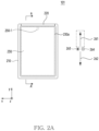
- FIG. 2A is a top plan view of an exemplary electronic device 101 in a first state.
- the electronic device 101 may include a first housing 210, a second housing 220 movable with respect to the first housing 210 in a first direction 261 parallel to a y-axis or in a second direction 262 parallel to the y-axis and opposite to the first direction 261, and a display 230 (e.g., the display).
- the electronic device 101 may be in the first state.
- the second housing 220 may be movable with respect to the first housing 210 in the first direction 261 among the first direction 261 and the second direction 262.
- the second housing 220 may not be movable in the second direction 262 with respect to the first housing 210.
- the display 230 may provide the display region having the smallest size.
- the display region may correspond to the region 230a.
- a region of a display 230 e.g., a region 230b of FIG. 2C ) different from the display region 230a may be included in the first housing 210.
- the region may be covered by the first housing 210.
- the region may be rolled into the first housing 210.
- the region 230a may include a planar portion, unlike the region including a curved portion. However, it is not limited thereto.
- the region 230a may include, in the first state, the curved portion extending from the planar portion and positioned in an edge portion.
- the first state may be referred to as a slide-in state or a closed state in terms of at least a portion of the second housing 220 being positioned in the first housing 210.
- the first state may be referred to as a minimized state in terms of providing the display region having the smallest size.
- it is not limited thereto.
- the first housing 210 may include a first image sensor 250-1 in a camera module 180, which is visually exposed through a portion of the region 230a and faces a third direction 263 parallel to the z-axis.
- the camera module 180 may be disposed to perform the function without being visually exposed through the portion of the region 230a in the internal space of the electronic device.
- the second housing 220 may include one or more second image sensors in the camera module 180 exposed through the portion of the second housing 220 and facing in a fourth direction 264 parallel to the z-axis and opposite to the third direction 263.
- the one or more second image sensors may be illustrated through the description of FIG. 2B .
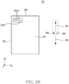
- FIG. 2B is a bottom view of an exemplary electronic device in a first state.
- one or more second image sensors 250-2 disposed in a second housing 220 may be positioned within a structure disposed in a first housing 210 for the one or more second image sensors 250-2.
- light from the outside of an electronic device 101 may be received by the one or more second image sensors 250-2 through a structure in the first state.
- the one or more second image sensors 250-2 since the one or more second image sensors 250-2 is positioned within the structure in the first state, the one or more second image sensors 250-2 may be exposed through the structure in the first state.
- the structure may be implemented in various ways.
- the structure may be an opening or a notch.
- the structure may be an opening 212a in a plate 212 of the first housing 210 surrounding at least a portion of the second housing 220.
- the one or more second image sensors 250-2 included in the second housing 220 may be covered by the plate 212 of the first housing 210.
- the first state may be changed to the second state.
- the first state (or the second state) may be changed to the second state (or the first state) through one or more intermediate states between the first state and the second state.
- the first state (or the second state) may be changed to the second state (or the first state) based on a predefined user input.
- the first state (or the second state) may be changed to the second state (or the first state) in response to a user input for a physical button exposed through a portion of the first housing 210 or the portion of the second housing 220.
- the first state (or the second state) may be changed to the second state (or the first state) in response to a touch input for an executable object displayed in the display region.
- the first state (or the second state) may be changed to the second state (or the first state) in response to a touch input having a contact point on the display region and a having press strength greater than the reference strength.
- the first state (or the second state) may be changed to the second state (or the first state) in response to a voice input received through the microphone of the electronic device 101.
- the first state (or the second state) may be changed to the second state (or the first state) in response to an external force applied to the first housing 210 and/or the second housing 220 to move the second housing 220 with respect to the first housing 210.
- the first state (or the second state) may be changed to the second state (or the first state) in response to a user input identified by an external electronic device (e.g., earbuds or smart watch) connected to the electronic device 101.
- an external electronic device e.g., earbuds or smart watch
- the second state may be exemplified through descriptions of FIGS. 2C and 2D .
- FIG. 2C is a top plan view of an exemplary electronic device in a second state.
- an electronic device 101 may be in the second state.
- a second housing 220 may be movable with respect to a first housing 210 in the second direction 262 among the first direction 261 and the second direction 262.
- the second housing 220 may not be movable in the first direction 261 with respect to the first housing 210.
- a display 230 may provide a display region having the largest size.
- the display region may correspond to a region 230c including a region 230a and a region 230b.
- the region 230b included in the first housing 210 in a first state may be visually exposed in the second state.
- the region 230a may include a planar portion.
- the region 230a may include a curved portion extending from the planar portion and positioned in an edge portion.
- the region 230b may include the planar portion among the planar portion and the curved portion, unlike the region 230a in the first state.
- the region 230b may include the curved portion extending from the planar portion of region 230b and positioned in the edge portion.
- the second state may be referred to as a slide-out state or an open state in terms of at least a portion of the second housing 220 being positioned outside the first housing 210.
- the second state may be referred to as an extended state in terms of providing the display portion having the largest size. However, it is not limited thereto.
- a first image sensor 250-1 facing a third direction 263 may be moved together with the region 230a according to the movement of the second housing 220 in the first direction 261.
- one or more second image sensors 250-2 facing a fourth direction 264 may be moved according to the movement of the second housing 220 in the first direction 261 when the state of the electronic device 101 is changed from the first state to the second state.
- the relative positional relationship between the one or more second image sensors 250-2 and the structure exemplified through the description of FIG. 2B may be changed according to the movement of the one or more second image sensors 250-2.
- the change of the relative positional relationship may be exemplified through FIG. 2D .
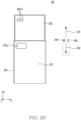
- FIG. 2D is a bottom view of an exemplary electronic device 101 in a second state.
- one or more second image sensors 250-2 may be positioned outside the structure.
- the one or more second image sensors 250-2 may be positioned outside an opening 212a in a plate 212.
- the one or more second image sensors 250-2 may be visually exposed in the second state.
- the relative positional relationship in the second state may be different from the relative positional relationship in the first state.
- the one or more second image sensors 250-2 in the second state may be visually exposed, unlike one or more second image sensors 250-2 in the first state.
- the electronic device 101 may be in an intermediate state between the first state and the second state.
- the size of the display region in the intermediate state may be larger than the size of the display region in the first state and smaller than the size of the display region in the second state.
- the display region in the intermediate state may correspond to a region including a portion of a region 230a and a region 230b.
- a portion of the region 230b may be exposed, and another portion (or remaining portion) of the region 230b may be covered by first housing 210 or may be rolled into the first housing 210.
- the electronic device 101 may include structures for moving a second housing (e.g., a second housing 220 of FIG. 2A ) of the electronic device 101 with respect to a first housing (e.g., the first housing 210 of FIG. 2A ) of the electronic device 101.
- a second housing e.g., a second housing 220 of FIG. 2A
- a first housing e.g., the first housing 210 of FIG. 2A
- the structures may be exemplified through descriptions of FIGS. 3A and 3B .
- FIGS. 3A and 3B are exploded perspective views of an exemplary electronic device.
- an electronic device 101 may include a first housing 210, a second housing 220, a display 230, and a driving unit 360.
- the first housing 210 may include a book cover 311, a plate 212, and a frame cover 313.
- the book cover 311 may at least partially form a side surface portion of an outer surface of the electronic device 101.
- the book cover 311 may at least partially form a rear surface portion of the outer surface.
- the book cover 311 may include an opening 311a for one or more second image sensors 250-2.
- the book cover 311 may include a surface supporting the plate 212.
- the book cover 311 may be coupled to the plate 212.
- the book cover 311 may include the frame cover 313.
- the book cover 311 may be coupled to the frame cover 313.
- the plate 212 may at least partially form the rear surface portion of the outer surface.
- the plate 212 may include an opening 212a for the one or more second image sensors 250-2.
- the plate 212 may be disposed on the surface of the book cover 311.
- the opening 212a may be aligned with the opening 311a.
- the frame cover 313 may be at least partially surrounded by the book cover 311.
- the frame cover 313 may be at least partially surrounded by the display 230.
- the frame cover 313 is at least partially surrounded by the display 230, but the position of the frame cover 313 may be maintained independently of the movement of the display 230.
- the frame cover 313 may be arranged in relation to at least some of the components of the display 230.
- the frame cover 313 may include rails 313a that provide (or guide) a path of the movement of at least one component of the display 230.
- the frame cover 313 may be coupled to at least one component of the electronic device 101.
- the frame cover 313 may support a rechargeable battery 189.
- the battery 189 may be supported through a recess or hole in a surface 313b of the frame cover 313.
- the frame cover 313 may be coupled to one end of a flexible printed circuit board (FPCB) 325 on a surface of the frame cover 313.
- FPCB flexible printed circuit board
- another end of the FPCB 325 may be connected to a PCB 324 through at least one connector.
- the PCB 324 may be electrically connected to another PCB (not illustrated in FIGS. 3A and 3B ) that supplies power to a motor 361 through the FPCB 325.
- the frame cover 313 may be coupled to at least one structure of the electronic device 101 for a plurality of states including the first state and the second state.
- the frame cover 313 may fasten the motor 361 of the driving unit 360.
- the second housing 220 may include a front cover 321 and a slide cover 322.
- the front cover 321 may be at least partially surrounded by the display 230.
- the front cover 321 may be coupled to at least a portion of a region 230a of the display 230 surrounding the front cover 321, unlike the frame cover 313, so that the display 230 is moved along the second housing 220 that is moved with respect to the first housing 210.
- the front cover 321 may be coupled to at least one component of the electronic device 101.
- the front cover 321 may be coupled to the printed circuit board (PCB) 324 including components of the electronic device 101.
- the PCB 324 may include a processor 120 (not illustrated in FIGS. 3A and 3B ).
- the front cover 321 may include the one or more second image sensors 250-2.
- the front cover 321 may be coupled to the at least one structure of the electronic device 101 for the plurality of states including the first state and the second state.
- the front cover 321 may fasten a rack gear 363 of the driving unit 360.
- the front cover 321 may be coupled to the slide cover 322.
- the slide cover 322 may be coupled to the front cover 321 to protect at least one component of the electronic device 101 coupled in the front cover 321 and/or at least one structure of the electronic device 101 coupled in the front cover 321.
- the slide cover 322 may include a structure for the at least one component.
- the slide cover 322 may include one or more openings 326 for the one or more second image sensors 250-2.
- the one or more openings 326 may be aligned with the one or more second image sensors 250-2 disposed on the front cover 321.
- the size of each of the one or more openings 326 may correspond to the size of each of the one or more second image sensors 250-2.
- the display 230 may include a support member 331.
- the support member 331 may include a plurality of bars.
- the plurality of bars may be coupled to each other.
- the driving unit 360 may include the motor 361, a pinion gear 362, and the rack gear 363.
- the motor 361 may operate based on power from the battery 189.
- the power may be provided to the motor 361 in response to the predefined user input.
- the pinion gear 362 may be coupled to the motor 361 through a shaft.
- the pinion gear 362 may be rotated based on the operation of the motor 361 transmitted through the shaft.
- the rack gear 363 may be arranged in relation to the pinion gear 362.
- teeth of the rack gear 363 may be engaged with teeth of the pinion gear 362.
- the rack gear 363 may move in a first direction 261 or a second direction 262 according to the rotation of the pinion gear 362.
- the second housing 220 may be moved in the first direction 261 and the second direction 262 by the rack gear 363 that is moved according to the rotation of the pinion gear 362 due to the operation of the motor 361.
- the first state of the electronic device 101 may be changed to a state different from the first state (e.g., the one or more intermediate states or the second state) through the movement of the second housing 220 in the first direction 261.
- the second state of the electronic device 101 may be changed to a state (e.g., the one or more intermediate states or the first state) different from the second state through the movement of the second housing 220 in the second direction 262.
- a state e.g., the one or more intermediate states or the first state
- changing the first state to the second state by the driving unit 360 and changing the second state to the first state by the driving unit 360 may be exemplified through FIGS. 4A and 4B .
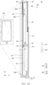
- FIG. 4A is a cross-sectional view of an exemplary electronic device in a first state.
- FIG. 4B is a cross-sectional view of an exemplary electronic device in a second state.
- a motor 361 may be operated based at least partially on the predefined user input received in a state 490, which is the first state.
- a pinion gear 362 may rotate in a first rotation direction 411 based at least partially on the operation of the motor 361.
- a rack gear 363 may be moved in a first direction 261, based at least partially on the rotation of the pinion gear 362 in the first rotation direction 411.
- the second housing 220 may be moved in the first direction 261 based at least partially on the movement of the rack gear 363 in the first direction 261.
- the display 230 may be moved based at least partially on the movement of the rack gear 363 in the first direction 261.
- the display 230 may be moved along rails 313a.
- the shape of at least some of the plurality of bars of the support member 331 of the display 230 may be changed when the state 490 is changed to a second state 495.
- a region 230b of the display 230 may be moved according to the movement of the display 230.
- the region 230b may be moved through a space between a book cover 311 and a frame cover 313.
- the region 230b in the state 495 may be visually exposed, unlike the region 230b rolled into the space in the state 490.
- the shape of the FPCB 325 may be changed when the state 490 is changed to the state 495.
- the motor 361 may be operated based at least partially on the predefined user input received in the state 495.
- the pinion gear 362 may be rotated in a second rotation direction 412 based at least partially on the operation of the motor 361.
- the rack gear 363 may be moved in a second direction 262, based at least partially on the rotation of the pinion gear 362 in the second rotation direction 412.
- the second housing 220 may be moved in the second direction 262 based at least partially on the movement of the rack gear 363 in the second direction 262.
- the display 230 may be moved based at least partially on the movement of the rack gear 363 in the second direction 262.
- the display 230 may be moved along the rails 313a.
- the shape of at least some of the plurality of bars of the support member 331 of the display 230 may be changed when the state 495 is changed to the state 490.
- the region 230b of the display 230 may be moved according to the movement of the display 230.
- the region 230b may be moved through the space between the book cover 311 and the frame cover 313 when the state 495 is changed to the state 490 according to the predefined user input.
- the region 230b in the state 490 may be rolled into the space, unlike the region 230b exposed in the state 495.
- the shape of the FPCB 325 may be changed when the state 495 is changed to the state 490.
- FIGS. 2A to 4B illustrate the electronic device 101 in which the height of the display region is changed and the width of the display region is maintained when the first state (or the second state) is changed to the second state (or the first state) in the portrait mode, but this is for convenience of description.
- the electronic device 101 may be implemented that the height of the display region is maintained and the width of the display region is changed, when the first state (or the second state) is changed to the second state (or the first state) in the portrait mode.
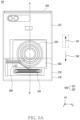
- FIG. 5A is a bottom view of an exemplary electronic device in a first state.
- FIG. 5B is a perspective view illustrating a portion of an exemplary electronic device in a first state.
- an electronic device 101 may include a first housing 210, a second housing 220, a first coil 510, and a flexible display 530 (e.g., a display 230 of FIG. 2A ).
- the second housing 220 may be coupled to the first housing 210 to be slidable in a first direction 261 parallel to the y-axis with respect to the first housing 210 or in a second direction 262 opposite to the first direction 261.
- the second housing 220 may move by sliding in the first direction 261 parallel to the y-axis with respect to the first housing 210 from the first state.
- the second housing 220 may be configured to change the electronic device 101 from the first state to the second state.
- the second housing 220 may move by sliding in the second direction 262 parallel to the y-axis and opposite to the first direction 261 with respect to the first housing 210 from the second state. As the second housing 220 moves in the second direction 262 with respect to the first housing 210, the second housing 220 may be configured to change the electronic device 101 from the second state to the first state.
- the flexible display 530 may include a first region 531 (e.g., a region 230a of FIG. 2A ) and a second region 532 (e.g., a region 230b of FIG. 2C ) extending from the first region 531.
- the first region 531 may be disposed on the second housing 220.
- the first region 531 may be included in the second housing 220.
- the second region 532 may be exposed to the outside as the second housing 220 moves in the first direction 261, or may be rolled into the first housing 210 as the second housing 220 moves in the second direction 262 opposite to the first direction 261.
- the first region 531 may be disposed on the second housing 220 and exposed to the outside.
- the second region 532 may be disposed in the first housing 210. Since the second housing 220 moves in the first direction 261 with respect to the first housing 210, the first region 531 may move in the first direction 261 along the second housing 220 while changing from the first state to the second state. Since the second region 532 extends from the first region 531, the second region 532 may be exposed to the outside by moving along the first region 531.
- the second region 532 may be exposed to the outside.
- the first region 531 may move in the second direction 262 along the second housing 220. Since the second region 532 extends from the first region 531, the second region 532 may be rolled into the first housing 210 by moving along the first region 531.
- a portion of the second region 532 may be exposed to the outside.
- the remaining portion of the second region 532 may be disposed in the first housing 210.
- the second region 532 may be configured to provide a plurality of states.
- the first state may be referred to as a slide-in state or a closed state in which the second region 532 is rolled into the first housing 210.
- the second state may be referred to as a slide-out state or an open state in which the second region 532 is exposed to the outside.
- the first coil 510 may facing at least the portion of the second region 532.
- the first coil 510 may overlap at least the portion of the second region 532 when the first housing 210 is viewed from above.
- the first coil 510 may be disposed in the first housing 210.
- the portion of the second region 532 disposed in the first housing 210 may overlap the first coil 510 when the first housing 210 is viewed from above.
- the second region 532 among the first region 531 and the second region 532 of the flexible display 530 exposed to the outside may partially overlap the first coil 510 when the first housing 210 is viewed from above.
- the first coil 510 may overlap the portion of the second region 532 disposed in the first housing 210 and the remaining portion of the second region 532 exposed to the outside.
- the first coil 510 may be disposed to overlap at least the portion of the second region 532 when the first housing 210 is viewed from above.
- the first coil 510 may be disposed on a portion of the first housing 210 overlapping the second region 532 disposed in the first housing 210 in the first state and overlapping the second region 532 exposed to the outside in the second state.
- the first coil 510 may be configured to receive power through an operation of a processor (e.g., a processor 120 of FIG. 1 ).
- the first coil 510 may be configured to raise the temperature of the second region 532 of the flexible display 530 based on the provided power.
- the first coil 510 may be configured to heat the second region 532 through the supplied power.
- the first coil 510 may receive the power by operating the processor 120 to supply power to the first coil 510 through a battery (e.g., a battery 189 of FIG. 1 ).
- the first coil 510 may be heated through the supplied power.
- the first coil 510 may overlap at least the portion of the second region 532 when the first housing 210 is viewed from above.
- the first coil 510 may face at least the portion of the second region 532.
- the heated first coil 510 may transfer heat through the supplied power to the second region 532.
- the second region 532 may be configured to raise the temperature of the second region 532 through the transferred heat.
- the first coil 510 may be configured to be disposed on the second region 532 so as to be able to heat the second region 532.
- an element when an element is referred to as being "on” another element, it should be understood that it is directly on the other element over (above) or intervening elements may exist therebetween.
- "B disposed on A” may represent “B disposed over A”.
- "B disposed on A” may represent "B faced away A”.
- the first coil 510 disposed on the second region 532 may represent "the first coil 510 contacting the second region 532".
- the first coil 510 disposed on the second region 532 may represent "the first coil 510 facing and separated from the second region 532".
- the first coil 510 may face and be separated from the second region 532. Since the first coil 510 faces the second region 532, the first coil 510 may transfer heat to the second region 532 through radiation heat transfer through power supplied through the operation of the processor 120.
- the first coil 510 may contact one component of the first housing 210 disposed between the second region 532 and the first coil 510.
- the first coil 510 may transfer heat to the second region 532 through heat conduction of the one component contacting with the first coil 510.
- a portion of the first coil 510 may face the second region 532, and the remaining portion except for the portion of the first coil 510 may contact one component of the first housing 210 disposed between the first coil 510 and the second region 532.
- the portion of the first coil 510 may transfer heat to the second region 532 through the radiation heat transfer.
- the remaining portion except for the portion of the first coil 510 may transfer heat to the second region 532 through the heat conduction of the one component of the first housing 210.
- the first coil 510 may face and be separated from the second region 532.
- the first coil 510 may heat air in the first housing 210 through power provided by the operation of the processor 120.
- the first housing 210 may include a structure that circulates air in the first housing 210 as the second housing 220 moves with respect to the first housing 210.
- the first coil 510 may transfer heat to the second region 532 through convection heat transfer as a portion of the air flows in the first housing 210 through the structure.
- the electronic device 101 may further include a second coil 520.
- the second coil 520 may be spaced apart from the first coil 510.
- the second coil 520 may be configured to receive power from the outside of the electronic device 101.
- the second coil 520 may wirelessly charge power to the battery 189 of the electronic device 101 through power transmitted from the outside.
- the second coil 520 may be a near field communication (NFC) antenna for wireless communication.
- NFC near field communication
- the second coil 520 through magnetic secure transmission, may be configured to receive information from an external electronic device (e.g., an electronic device 104 of FIG. 1 ) to the electronic device 101 or may be configured to transmit information from the electronic device 101 to the external electronic device 104.
- the second coil 520 may overlap at least the portion of the second region 532 when the first housing 210 is viewed from above.
- the second coil 520 may be spaced apart from the first coil 510 and may be overlapped with another portion of the second region 532, which is distinct from the portion of the second region 532 overlapping the first coil 510 when the first housing 210 is viewed from above.
- the second coil 520 may be heated through wireless power charge through wireless charging from the outside of the electronic device 101.
- the second coil 520 may be heated by receiving power from the battery 189 of the electronic device 101 based on the operation of the processor 120.
- the heated second coil 520 may face the second region 532 and transfer heat to the second region 532 through the radiation heat transfer.
- the heated second coil 520 may contact at least one component of the electronic device 101 between the second coil 520 and the second region 532.
- the second coil 520 may heat the second region 532 through the heat conduction of the at least one component.
- the first housing 210 may include a cover 540 (e.g., a book cover 311 of FIG. 3A ).
- the cover 540 may enclose at least a portion of the flexible display 530.
- the cover 540 may include an outer surface 541 facing the outside of the electronic device 101 and an inner surface 542 opposite to the outer surface.
- the inner surface 542 may face the flexible display 530.
- the inner surface 542 may be a portion of the cover 540 that surrounds at least a portion of the flexible display 530.
- the cover 540 may surround at least a portion of the second region 532 disposed in the first housing 210 in the first state.
- At least the portion of the second region 532 may be disposed between the cover 540 and a frame cover (e.g., a frame cover 313 of FIG. 3A ). At least the portion of the second region 532 may face the inner surface 542 of the cover 540 facing the flexible display 530.
- the cover 540 may support the first coil 510.
- the first coil 510 may contact at least the portion of the cover 540.
- the first coil 510 may be attached to the cover 540.
- the portion of the cover 540 on which the first coil 510 is disposed may overlap at least the portion of the second region 532 when the first housing 210 is viewed from above.
- the portion of the cover 540 on which the first coil 510 is disposed may face the second region 532.
- the cover 540 surrounding at least the portion of the second region 532 may be configured so that the first coil 510 overlaps at least the portion of the second region 532 when the first housing 210 is viewed from above, by supporting the first coil 510.
- the second coil 520 may be disposed on the outer surface 541 of the cover 540 to receive power from the outside of the electronic device 101.
- the second coil 520 may be configured to receive power from the external electronic device (e.g., the electronic device 104 of FIG. 1 ).
- the first housing 210 may further include a plate (e.g., plate 212 of FIG. 2A ) disposed on the cover 540.
- the second coil 520 may contact the outer surface 541 of the cover 540 facing the plate 212.
- the second coil 520 may be disposed between the cover 540 and the plate 212.
- the second coil 520 may pass through the plate 212 and receive power received by the second coil 520.
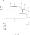
- the electronic device 101 may further include a flexible printed circuit board 550.
- the flexible printed circuit board 550 may connect the first coil 510 and the second coil 520.
- the flexible printed circuit board 550 may be another FPCB, distinct from a FPCB 325 of FIG. 3A .
- the second coil 520 may be electrically connected to the first coil 510 through the flexible printed circuit board 550.
- the flexible printed circuit board 550 may be disposed on the cover 540.
- the flexible printed circuit board 550 may include a circuit connecting between the second coil 520 and the first coil 510.
- the flexible printed circuit board 550 may be electrically connected to the battery 189 of the electronic device 101.
- the power transferred from the battery 189 to the flexible printed circuit board 550 may be provided to the first coil 510 and/or the second coil 520 through the flexible printed circuit board 550.
- the power transferred from the battery 189 to the second coil 520 may be provided to the first coil 510 through the circuit connecting the second coil 520 and the first coil 510.
- the power transferred from the external electronic device 104 to the second coil 520 may be provided to the first coil 510 through the circuit connecting the second coil 520 and the first coil 510.
- the first coil 510 and the second coil 520 may be included in the flexible printed circuit board 550.
- the first coil 510, the second coil 520, and the flexible printed circuit board 550 may configure an antenna module.
- the second coil 520 may be an NFC antenna.
- the second coil 520 may receive power through the wireless power charge from the outside.
- the second coil 520 may be configured to provide the received power to the first coil 510 connected to the second coil 520 through the flexible printed circuit board 550.
- the electronic device 101 may include a sensor 560 (e.g., a sensor module 176 of FIG. 1 ) for measuring the temperature of the second region 532.
- a sensor 560 e.g., a sensor module 176 of FIG. 1 .
- the senor 560 may sense the temperature inside electronic device 101.
- the sensor 560 may be a temperature sensor configured to sense the temperature of the second region 532 based on the temperature inside the electronic device 101.
- the senor 560 may overlap the second region 532 when the first housing 210 is viewed from above, in order to sense the temperature of the second region 532.
- the sensor 560 may face the second region 532 by being disposed on the inner surface 542 of the cover 540 enclosing at least the portion of the second region 532.
- the sensor 560 may be disposed on the flexible printed circuit board 550 disposed on the cover 540.
- the senor 560 may sense power provided to the first coil 510 and/or the second coil 520.
- the sensor 560 may sense the temperature of the second region 532 raised by the heating of the first coil 510 and/or the second coil 520 based on the data on the sensed power.
- the processor may be configured to obtain data representing the temperature of the second region 532 and may be configured to supply power to the first coil 510 based on at least a portion of the data.
- the processor 120 may be configured to supply the power to the second coil 520 electrically connected to the first coil 510.
- the processor 120 may be connected to the sensor 560.
- the processor 120 may be configured to obtain the data representing the temperature of the second region 532 sensed by the sensor 560. Based on identifying that the data representing the temperature of the second region 532 is less than the reference temperature, the processor 120 may be configured to supply power to the first coil 510 through the battery 189 of the electronic device 101 and/or a power supply module.
- the processor 120 may be configured to supply at least a portion of power provided to the second coil 520 from the outside to the first coil 510. Based on at least a portion of the data representing the temperature of the second region 532 (e.g., data representing the temperature of the second region 532 lower than the reference temperature), the processor 120 may be configured to heat the second region 532 through heating of the first coil 510 by supplying power to the first coil 510. The processor 120 may be configured to raise the temperature of the second region 532 through heating of the first coil 510.
- the electronic device 101 may heat the second region 532 by including the first coil 510 and/or the second coil 520 overlapping at least the portion of the second region 532 of the flexible display when the first housing 210 is viewed from above.
- the electronic device 101 may raise the temperature of the second region 532 above the reference temperature, by being configured to heat the first coil 510 and/or the second coil 520 based on at least a portion of the data representing the temperature of the second region 532.
- the electronic device 101 may reduce damage to the second region 532 that is deformed while performing a slide-out operation in which the electronic device 101 changes from the first state to the second state at a low temperature or while performing a slide-in operation to change from the second state to the first state at the low temperature, by being configured to raise the temperature of the second region 532 above the reference temperature.
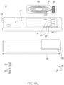
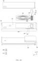
- FIGS. 6A , 6B , and 6C are exploded views of an exemplary electronic device.
- the electronic device 101 may include a first housing 210, a first coil 510, a second coil 520, a flexible display 530 (e.g., a display 230 of FIG. 2A ), and a flexible printed circuit board 550.
- the first housing 210 may include a cover 540 (e.g., a book cover 311 of FIG. 3A ).
- the cover 540 may include at least one slit 610 overlapping the first coil 510.
- the at least one slit 610 may be covered by the first coil 510.
- the at least one slit 610 may overlap the first coil 510 when the first housing 210 is viewed from above.
- the at least one slit 610 may be included in one region of the cover 540 on which the first coil 510 is disposed.
- a second region 532 (e.g., region 230b of FIG. 2C ) of the flexible display 530 may face the first coil 510 through the at least one slit 610.
- the first coil 510 may heat the second region 532 by facing the second region 532 through the at least one slit 610.
- the first coil 510 may be disposed on an outer surface 541 facing the outside of the cover 540. The first coil 510 may overlap the at least one slit 610 when the first housing 210 is viewed from above.
- the first coil 510 may face at least a portion of the second region 532 surrounded by the inner surface 542, through the at least one slit 610 extending from the outer surface 541 of the cover 540 to the inner surface 542 of the cover 540.
- the first coil 510 may heat the second region 532 through radiation heat transfer through the at least one slit 610, by heating with power provided to the first coil 510 through a battery (e.g., a battery 189 in FIG. 1 ) or a power supply module.
- the at least one slit 610 may include a plurality of slits contacting the first coil 510.
- the at least one slit 610 may include slits 611, 612, and 613.
- the slits 611, 612, and 613 may be spaced apart from each other.
- Each of the slits 611, 612, and 613 may contact the first coil 510.
- Each of the slits 611, 612, and 613 may overlap the first coil 510 when the first housing 210 is viewed from above.
- the first coil 510 may be supported through a portion of the cover 540 disposed between the slits 611, 612, and 613.
- the first coil 510 may heat the second region 532 through each of the slits 611, 612, and 613.
- the cover 540 may include a third region 543 contacting the first coil 510 and a fourth region 544 enclosing the third region 543.
- the third region 543 may be an region overlapping the first coil 510 when the first housing 210 is viewed from above.
- the third region 543 may support the first coil 510.
- the fourth region 544 may be a region on which the second coil 520 is disposed.
- the third region 543 may be separated from the fourth region 544.
- the cover 540 may include a gap disposed between the third region 543 and the fourth region 544.
- the third region 543 may be attached to the first coil 510 and/or the flexible printed circuit board 550 on which the first coil 510 is disposed.
- the cover 540 may include an insulator disposed in the gap between the third region 543 and the fourth region 544. As the third region 543 of the cover 540 on which the first coil 510 is disposed is separated from the fourth region 544 of the cover 540, the cover 540 may block heat transferred from the first coil 510 to the third region 543 from being transferred to the fourth region 544.
- the heat transferred from the first coil 510 to the third region 543 may be transferred to the second region 532 through heat conduction of the third region 543.
- the first coil 510 may transfer radiation heat to the second region 532 through the gap disposed between the third region 543 and the fourth region 544.
- the third region 543 may be formed through a double injection molding process of the cover 540.
- the thermal conductivity of the third region 543 may be higher than the thermal conductivity of the fourth region 544.
- the third region 543 may be configured with a material different from the fourth region 544 of the cover 540 enclosing the third region 543. Since the thermal conductivity of the third region 543 is higher than the thermal conductivity of the fourth region 544, the first coil 510 may raise the amount of heat transferred to the second region 532 than the fourth region 544 through the third region 543.
- the first housing 210 may include a plate 212 disposed on the cover 540 and a heat insulating member 620 disposed between the cover 540 and the plate 212.
- the heat insulating member 620 may surround the first coil 510.
- the heat insulating member 620 may be disposed on the flexible printed circuit board 550 on which the first coil 510 is disposed.
- the heat insulating member 620 may cover a portion of the first coil 510 facing the plate 212. As the heat insulating member 620 covers the portion of the first coil 510, the heat insulating member 620 may reduce damage to the plate 212 due to high heat of the first coil 510.
- the electronic device 101 may be configured to efficiently transfer heat from the first coil 510 to the second region 532 of the flexible display 530, by including the at least one slit 610 in the cover 540.
- the electronic device 101 may be configured to efficiently transfer heat from the first coil 510 to the second region 532.
- the first coil 510 may reduce damage to the second region 532 that is deformed while performing a slide-out operation in which the electronic device 101 changes from the first state to the second state at a low temperature or while performing a slide-in operation to change from the second state to the first state at the low temperature, by being configured to raise the temperature of the second region 532 above the reference temperature.
- the first housing 210 may reduce damage to the plate 212 due to the high heat of the first coil 510 by including the heat insulating member 620 disposed between the cover 540 and the plate 212.
- FIG. 6D is a cross-sectional view of an exemplary electronic device for line A-A' of FIG. 5A .
- an electronic device 101 may include a first housing 210, a first coil 510, a second coil 520, a flexible display 530 (e.g., a display 230 of FIG. 2A ), and a flexible printed circuit board 550.
- the first housing 210 may include a cover 540 (e.g., a book cover 311 of FIG. 3A ) and a heat insulating member 620.
- the cover 540 may include a third region 543 on which the first coil 510 is disposed, and a fourth region 544 surrounding the third region 543.
- a thickness d1 of the third region 543 may be thinner than a thickness d2 of the fourth region 544.
- the first coil 510 may be disposed on the outer surface 541 facing the outside of the cover 540.
- the cover 540 may transfer more heat transferred from the first coil 510 to the third region 543 to the second region 532 of the flexible display 530 than when the thickness of the third region 543 is the same as the thickness d4 of the fourth region 544.
- the flexible printed circuit board 550 may include a first portion 551 on which the first coil 510 is disposed and a second portion 552 on which the second coil 520 is disposed extending from the first portion 551.
- a thickness d3 of the first portion 551 may be thinner than a thickness d4 of the second portion 552.
- the second portion 552 may contact a plate 212.
- the first housing 210 may include a space in which the heat insulating member 620 may be disposed between the first portion 551 and the plate 212.
- the heat insulating member 620 may be omitted.
- the first housing 210 may include a space between the first coil 510 and the plate 212 disposed on the first portion 551.
- the first housing 210 may reduce damage to the plate 212 due to high heat of the first coil 510 by including the space.
- the electronic device 101 may be configured to enable efficient heat transfer from the first coil 510 to the second region 532 of the flexible display 530.
- the cover 540 may be configured to enable efficient heat transfer from the first coil 510 to the second region 532 of the flexible display 530.
- the first coil 510 may reduce damage to the second region 532 that is deformed while performing a slide-out operation in which the electronic device 101 changes from the first state to the second state at a low temperature or while performing a slide-in operation to change from the second state to the first state, by being configured to raise the temperature of the second region 532 above the reference temperature.
- the flexible printed circuit board 550 may reduce damage to the plate 212 toward which the first coil 510 faces due to high heat of the first coil 510.
- FIG. 7A illustrates a portion of an exemplary electronic device.
- FIG. 7B is a side view of an exemplary electronic device of FIG. 7A .
- FIG. 7C illustrates a portion of an exemplary electronic device.
- an electronic device 101 may include a first housing 210, a first coil 510, a second coil 520, a flexible display 530 (e.g., a display 230 of FIG. 2A ), and a flexible printed circuit board 550.
- the first housing 210 may include a cover 540 (e.g., a book cover 311 of FIG. 3A ).
- an inner surface 542 facing the flexible display 530 of the cover 540 may support the first coil 510.
- the coil 510 may be disposed on the inner surface 542.
- the first coil 510 may contact the inner surface 542 surrounding at least a portion of the second region 532 of the flexible display 530.
- the first coil 510 may contact the inner surface 542 and face the second region 532.
- the first coil 510 may be heated by power supplied through a battery of the electronic device 101 (e.g., a battery 189 of FIG. 1 ) and/or a power supply module of the electronic device. Since the first coil 510 faces the second region 532, the heated first coil 510 may transfer the heat to the second region 532.
- the cover 540 may include a through hole 710 extending between an outer surface 541 facing the outside of the electronic device 101 and an inner surface 542 facing the flexible display 530.
- the flexible printed circuit board 550 may pass through the through hole 710.
- the flexible printed circuit board 550 may connect the second coil 520 disposed on the outer surface 541 and the first coil 510 disposed on the inner surface 542, by passing through the through hole 710.
- the flexible printed circuit board 550 may include a first portion 551 on which the first coil 510 is disposed, and a second portion 552 on which the second coil 520 is disposed.
- the first portion 551 may be disposed on the inner surface 542 of the cover 540 facing the flexible display 530, and the second portion 552 may be disposed on the outer surface 541 of the cover 540 facing the outside.
- a portion of the flexible printed circuit board 550 connecting the first portion 551 and the second portion 552 may connect the first portion 551 and the second portion 552 through the through hole 710 extending from the outer surface 541 to the inner surface 542.
- the first coil 510 and the second coil 520 may be connected.
- the first coil 510 may be omitted.
- the second coil 520 may overlap the second region 532 of the flexible display 530 when viewed from above.
- the second coil 520 may be configured to heat the second region 532.
- the second coil 520 may contact the outer surface 541 of the cover 540 in order to receive power from the outside of the electronic device 101.
- the second coil 520 may be configured to heat the second region 532 by receiving power from an external electronic device (e.g., an electronic device 104 of FIG. 1 ).
- the second coil 520 may be electrically connected to a battery (e.g., a battery 189 of FIG. 1 ) and/or a power supply module of the electronic device 101.
- the second coil 520 may be configured to heat the second region 532 through power supplied from the battery 189 and/or the power supply module.
- the flexible printed circuit board 550 may include a circuit connecting the second coil 520 and the battery 189 and/or the power supply module.
- the electronic device 101 may be configured to reduce power consumption by the first coil 510 and provide a space for an internal component of the electronic device 101.
- the electronic device 101 may be configured to heat the second region 532 of the flexible display 530 through the first coil 510 disposed on the inner surface 542 of the cover 540 facing the flexible display 530.
- the cover 540 may allow the flexible printed circuit board 550 connecting the first coil 510 and the second coil 520 to pass through, by including the through hole 710 passing through the cover 540.
- the first coil 510 may receive power from the second coil 520 by being connected to the second coil 520.
- the first coil 510 may reduce damage to the second region 532 that is deformed while performing a slide-out operation in which the electronic device 101 changes from the first state to the second state at a low temperature or while performing a slide-in operation to change from the second state to the first state at the low temperature, by disposed on the inner surface 542 and configured to heat the second region 532 to raise the temperature of the second region 532 above the reference temperature.
- the first coil 510 may be omitted.
- the second coil 520 may be configured to raise the temperature of the second region 532 above the reference temperature.
- the electronic device 101 may be configured to reduce power consumption by the first coil 510 and provide the space for the internal component of the electronic device 101.
- FIG. 8 illustrates an example of an operation of a processor of an exemplary electronic device.
- FIG. 8 may be performed by an electronic device 101 of FIGS. 5A and 5B .
- a processor may identify a flexible display (e.g., display 230 of FIG. 2A ) rolled into a first housing (e.g., a first housing 210 of FIG. 2A ), a second region (e.g., a region 230b of FIG. 2C or a second region 532 of FIG. 5A ) of a flexible display 530 of FIG. 5A .
- a first housing e.g., a first housing 210 of FIG. 2A
- a second region e.g., a region 230b of FIG. 2C or a second region 532 of FIG. 5A
- the processor 120 may be configured to identify a first state corresponding to a slide-in state.
- the processor 120 may identify the second region 532 rolled into the first housing 210 along the second housing 220 which is at least partially positioned in the first housing 210, based on identifying the second housing (e.g., the second housing 220 of FIG. 2A ) at least partially positioned in the first housing 210.
- the processor 120 may sense the temperature of the second region 532 rolled into the first housing 210.
- the processor 120 may be configured to sense the temperature of the second region 532 or may be configured to obtain data representing the temperature, through a sensor (e.g., a sensor module 176 of FIG. 1 and a sensor 560 of FIG. 5A ) configured to sense the temperature of the second region 532.
- a sensor e.g., a sensor module 176 of FIG. 1 and a sensor 560 of FIG. 5A
- the processor 120 may identify whether the temperature of the second region 532 rolled into the first housing 210 is less than a threshold temperature T1. According to an embodiment, the processor 120 may bypass supplying power P1 or power P2 lower than the power P1 to a first coil (e.g., a first coil 510 of FIG. 5A ), based on identifying that the temperature of the second region 532 rolled into the first housing 210 is equal to or higher than the threshold temperature T1. The processor 120 may supply the power P2 lower than the power P1 or the power P1 to the first coil 510, based on identifying that the temperature of the second region 532 rolled into the first housing 210 is less than the threshold temperature T1.
- a first coil e.g., a first coil 510 of FIG. 5A
- the processor 120 may be configured to provide the power P1 or the power P2 lower than the power P1 to a second coil (e.g., a second coil 520 of FIG. 5A ) connected to the first coil 510, based on identifying that the temperature of the second region 532 is less than the threshold temperature T1.
- a second coil e.g., a second coil 520 of FIG. 5A
- the processor 120 may be configured to provide power P1 to the first coil (e.g., the first coil 510 of FIG. 5A ), based on the data representing the temperature of the second region 532 below the threshold temperature T1.
- the processor 120 may be configured to supply power P1 to the first coil 510 through a battery (e.g., a battery 189 of FIG. 1 ) and/or a power supply module, while identifying that the data representing the temperature of the second region 532 is less than the threshold temperature T1 through the sensor 560 configured to sense the temperature of the second region 532.
- the first coil 510 may heat the second region 532 by being heated through the supplied power, thereby increasing the temperature of the second region 532.
- the electronic device 101 may include the second coil (e.g., the second coil of FIG. 5A ) electrically connected to the first coil 510 and configured to receive the power P1 from the processor 120 based on the data representing the temperature of the second region 532.
- the processor 120 may be configured to bypass providing the power P1 to the second coil 520 among the first coil 510 and the second coil 520 based on identifying that the power P1 is provided to the first coil 510 and the second coil 520 during a reference time.
- the processor 120 may be configured to supply the power P1 to the first coil 510 and the second coil 520 to raise the temperature of the second region 532 to the temperature corresponding to the threshold temperature T1, based on the data representing the temperature of the second region 532 below the threshold temperature T1. Based on identifying that the power P1 has been supplied to the first coil 510 during a specified time, the processor 120 may be configured to bypass supplying the power P1 to the second coil 520. The processor 120 may raise the temperature of the second region 532 to the threshold temperature T1 in a shorter time than raising the temperature of the second region 532 to the threshold temperature T1 only with the first coil 510, by being configured to supply the power P1 to the second coil 520. The processor 120 may reduce the power consumption of the electronic device 101, by being configured to bypass supplying the power P1 to the second coil 520 based on identifying that the power P1 is supplied to the first coil 510 during the specified time.
- the processor 120 may identify whether the temperature of the second region 532 is above the threshold temperature T1 and below another threshold temperature T2 higher than the threshold temperature T1. According to an embodiment, the processor 120 may be configured to provide the power P2 lower than the power P1 to the first coil 510 based on the data representing the temperature of the second region 532 above the threshold temperature T1. According to an embodiment, the processor 120 may be configured to bypass supplying power to the first coil 510, based on the data representing the temperature of the second region 532 that is equal to or higher than another threshold temperature T2 higher than the threshold temperature T1.
- the processor 120 may be configured to maintain that the power P2 lower than the power P1 is provided to the first coil 510, based on the data representing the temperature of the second region 532 above the threshold temperature T1 and below another threshold temperature T2 higher than the threshold temperature T1.
- the processor 120 may reduce the power consumption of the electronic device 101, by being configured to provide another power P2 lower than the power P1 to the first coil 510, based on identifying the temperature of the second region 532 that is above the threshold temperature T1 and below another threshold temperature T2 higher than the threshold temperature T1.
- the processor 120 may be configured to bypass providing the power P1 or the power P2 lower than the power P1 to the first coil 510, based on the data representing the temperature of the second region 532 that is equal to or higher than another threshold temperature T2 higher than the threshold temperature T1.
- the processor 120 of the electronic device 101 may be configured to sense the temperature of the second region 532, based on identifying the first state corresponding to the slide-in state in which the second region 532 of the flexible display 530 is rolled into the first housing 210.
- the processor 120 may be configured to raise the temperature of the second region 532 to the threshold temperature T1 through the first coil 510, by being configured to provide the power P1 to the first coil 510, based on the data representing the temperature of the second region 532 below the threshold temperature T1.
- the first coil 510 may reduce damage to the second region 532 that is deformed while performing a slide-out operation in which the electronic device 101 changes from the first state to the second state at a temperature lower than the threshold temperature T1, by being configured to raise the temperature of the second region 532 above the threshold temperature T1.
- the processor 120 may reduce the power consumption of the electronic device 101, by being configured to provide the power P2 lower than the power P1 to the first coil 510, or bypass power supply to the first coil 510, based on the data representing the temperature of the second region 532 equal to or higher than the threshold temperature T1.
- FIG. 9 illustrates an example of an operation of a processor of an exemplary electronic device.
- FIG. 9 may be performed by an electronic device 101 of FIGS. 5A and 5B .
- a processor may identify an event to expose a second region (e.g., a region 230b of FIG. 2C and a second region 532 of FIG. 5A ) rolled into a first housing (e.g., a first housing 210 of FIG. 2A ) to the outside.
- a second region e.g., a region 230b of FIG. 2C and a second region 532 of FIG. 5A
- the event for exposing the second region 532 to the outside may be a slide-out operation.
- the event for exposing the second region 532 may be an operation in which the electronic device 101 changes from a first state in which the second region 532 is rolled into the first housing 210 to a second state in which the second region 532 is exposed to the outside.
- the event for exposing the second region 532 to the outside may be an operation in which the second housing 220 moves in a first direction (e.g., a first direction 261 of FIG. 1 ) with respect to the first housing 210 to expose the second region 532.
- a first direction e.g., a first direction 261 of FIG. 1
- the processor 120 may sense the temperature of the second region 532, based on identifying the second region 532 rolled into the first housing 210.
- the operation 902 may be an operation corresponding to operation 801 and operation 802 of FIG. 8 .
- the processor 120 may identify whether the temperature of the second region 532 rolled into the first housing 210 is less than a threshold temperature T1.
- the processor 120 may be configured to bypass supplying the power P1 to a first coil (e.g., a first coil 510 of FIG. 5A ) based on identifying that the temperature of the second region 532 rolled into the first housing 210 is above the threshold temperature T1.
- the processor 120 may be configured to expose the second region 532 to the outside in response to the event to expose the second region 532 to the outside, based on identifying that the temperature of the second region 532 rolled into the first housing 210 is equal to or higher than the threshold temperature T1.
- the processor 120 may supply the power P1 to the first coil 510, based on identifying that the temperature of the second region 532 rolled into the first housing 210 is less than the threshold temperature T1. According to an embodiment, the processor 120 may be configured to stop exposing the second region 532 rolled into the first housing 210 to the outside, based on identifying that the temperature of the second region 532 is less than the threshold temperature T1.
- the processor 120 may provide the power P1 to the first coil (e.g., the first coil 510 of FIG. 5A ) to raise the temperature of the second region to the threshold temperature T1, and may stop exposing the second region 532 to the outside.
- the first coil e.g., the first coil 510 of FIG. 5A
- the processor 120 may identify whether the power P1 has been supplied to the first coil 510 while identifying that the temperature of the second region 532 rolled into the first housing 210 is above the threshold temperature T1.
- the processor 120 may be configured to move the second housing 220 at a speed v1 in the first direction (e.g., the first direction 261 of FIG. 2A ) with respect to the first housing 210, in response to the event exposing the second region 532 to the outside, based on identifying that the power P1 is not supplied to the first coil 510.
- the processor 120 may be configured to move the second housing 220 at a speed v2 different from the speed v 1 in the first direction 261 with respect to the first housing 210, in response to the event, based on identifying that the power P1 is supplied to the first coil 510.
- the processor 120 may identify that the power P1 is not supplied to the first coil 510, may bypass providing power to the first coil 510 in response to the event for exposing the second region 532 to the outside while identifying that the temperature of the second region 532 rolled into the first housing 210 is equal to or higher than the threshold temperature T1, and may move the second housing 220 in the first direction 261 with respect to the first housing 210 to expose the second region 532 to the outside.
- the processor 120 may identify that the power P1 is supplied to the first coil 510, may bypass providing the power P1 to the first coil 510 in response to the event to expose the second region 532 to the outside while identifying that the temperature of the second region 532 rolled into the first housing 210 is equal to or higher than the threshold temperature T1, and may move the second housing 220 in the first direction 261 with respect to the first housing 210 to expose the second region 532 to the outside.
- the speed v2 at which the second region 532 is moved to expose the second region 532 to the outside after the power P1 is provided to the first coil 510 may be lower than the speed v1 at which the second region 532 is moved to expose the second region 532 to the outside after the power P1 provided to the first coil 510 is bypassed in the operation 906.
- the processor 120 may reduce damage to the second region 532 heated through the first coil 510 by moving at a speed v1 higher than the speed v2.
- the processor 120 of the electronic device 101 may be configured to identify the event to expose the second region 532 to the outside in the first state corresponding to the slide-in state in which the second region 532 of the flexible display 530 is rolled into the first housing 210.
- the processor 120 may be configured to sense the temperature of the second region 532 in response to the event.
- the processor 120 may be configured to raise the temperature of the second region 532 to the threshold temperature T1 through the first coil 510, by being configured to provide the power P1 to the first coil 510, based on the data representing the temperature of the second region 532 below the threshold temperature T1.
- the first coil 510 may reduce damage to the second region 532 deformed while the electronic device 101 performs the operation to expose the second region 532 to the outside in response to the event at the temperature lower than the threshold temperature T1, by being configured to raise the temperature of the second region 532 above the threshold temperature T1.
- the processor 120 may reduce damage to the second region 532, by performing the slide-out operation at a slower speed than in case that the power P1 is not supplied, based on identifying that the power P1 has been supplied, while identifying that the temperature of the second region 532 is equal to or higher than the threshold temperature T1.
- FIG. 10 is a timing diagram illustrating an operation of an exemplary electronic device.
- a processor e.g., a processor 120 of FIG. 1 of an electronic device (e.g., an electronic device 101 of FIG. 1 ) controls supplying power to a first coil (e.g., a first coil 510 of FIG. 5A ) based on the temperature of a second region (e.g., a region 230b of FIG. 2A , a second region 532 of FIG. 5A ) of a flexible display (e.g., a display 230 of FIG. 2A , a flexible display 530 of FIG.
- a first coil e.g., a first coil 510 of FIG. 5A
- a second region e.g., a region 230b of FIG. 2A , a second region 532 of FIG. 5A
- a flexible display e.g., a display 230 of FIG. 2A , a flexible display 530 of FIG.
- the timing diagram 1000 may represent a time relation between an operation to heat the second region 532 of the electronic device 101 and a slide-out operation to expose the second region 532 to the outside.
- a horizontal axis of each of a plurality of graphs in the timing diagram 1000 may represent time.
- the processor 120 may be configured to change a state (e.g., a state of the timing diagram 1000) of electronic device 101. During a time duration between a timing 1010 and a timing 1020, it may be configured to perform a slide-in operation to change the second region 532 from a second state exposed to the outside to a first state in which the second region 532 is rolled into a first housing (e.g., a first housing 210 of FIG. 2A ).
- a state e.g., a state of the timing diagram 1000
- a time duration between a timing 1010 and a timing 1020 it may be configured to perform a slide-in operation to change the second region 532 from a second state exposed to the outside to a first state in which the second region 532 is rolled into a first housing (e.g., a first housing 210 of FIG. 2A ).
- the processor 120 may be configured to sense the temperature of the second region 532 (e.g., D2_Temp of the timing diagram 1000) based on identifying the second region 532 rolled into the first housing 210 at the timing 1020.
- the processor 120 may be configured to identify whether the temperature of the second region 532 is less than a threshold temperature T1, through a sensor (e.g., a sensor module 176 of FIG. 1 and a sensor 560 of FIG. 5A ).
- the processor 120 may be configured to heat (e.g., C1_Heat of the timing diagram 1000) the first coil 510 by supplying power to the first coil 510, based on identifying that the temperature of the second region 532 rolled into the first housing 210 is below the threshold temperature T1, during the time duration between the timing 1020 and a timing 1030.
- heat e.g., C1_Heat of the timing diagram 1000
- the processor 120 may identify whether the temperature of the second region 532 is less than the threshold temperature T1 during a specified time duration s2 according to a specified time interval s1, based on identifying the second region 532 rolled into the first housing 210, during the time duration between the timing 1020 and the timing 1030.
- the processor 120 may be configured to provide power to the first coil 510 from the timing when it identifies that the temperature is less than the threshold temperature T1, in the specified time duration s2, based on identifying that the temperature of the second region 532 is less than the threshold temperature T1.
- the processor 120 may be configured to bypass providing the power to the first coil 510 during the specified time duration s2 in the specified time duration s2 based on identifying that the temperature of the second region 532 is above the threshold temperature T1.
- the processor 120 may identify an event for exposing the second region 532 to the outside at the timing 1030.
- the processor 120 may stop exposing the second region 532 to the outside based on identifying the event and identifying that the second region 532 is less than the threshold temperature T1.
- the processor 120 may be configured to supply power to the first coil 510 to raise the temperature of the second region 532 to the threshold temperature T1, based on identifying that the temperature of the second region 532 is less than the threshold temperature T1 during the time duration between the timing 1030 and a timing 1040.
- the processor 120 may be configured to perform the slide-out operation to change from the first state in which the second region 532 is rolled into the first housing 210 to the second state in which the second region 532 is exposed to the outside, in response to an event to expose the second region 532 to the outside, during the time duration between the timing 1040 and a timing 1050, based on identifying that the temperature of the second region 532 is equal to or higher than the threshold temperature T1 at the timing 1040.
- the processor 120 may be configured to perform the slide-out operation at a speed lower than the speed of performing the slide-out operation without supplying the power based on identifying that power has been supplied to the first coil 510 during the time duration between the timing 1040 and the timing 1050.
- the processor 120 of the electronic device 101 may be configured to raise the temperature of the second region 532 to the threshold temperature T1 through the first coil 510, by being configured to provide power to the first coil 510 based on identifying the temperature of the second region 532 below the threshold temperature T1.
- the first coil 510 may reduce damage to the second region 532 that is deformed, while performing an operation to expose the second area 532 to the outside, in response to an event in which the electronic device 101 exposes the second region 532 at a temperature lower than the threshold temperature T1, by being configured to raise the temperature of the second region 532 to above the threshold temperature T1.
- the processor 120 may identify whether the temperature of the second region 532 is less than the threshold temperature T1 during the specified time duration s2 according to the specified time interval s1 based on identifying the state in which the second region 532 is rolled into the first housing 210.
- the processor 120 may reduce power consumption of the electronic device 101, by being configured to heat the second region 532 during the specified time duration s2, based on identifying that the temperature of the second region 532 is less than the threshold temperature T1 during the specified time duration s2.
- an electronic device may comprise a first housing (e.g., a first housing 210 of FIG. 2A ), a second housing (e.g., a second housing 220 of FIG. 2A ) coupled with the first housing so as to slidable in a first direction (e.g., a first direction 261 of FIG. 2A ) or a second direction (e.g., a second direction 262 of FIG. 2A ) opposite to the first direction with respect to the first housing.
- the electronic device may further comprise a display including a first region (e.g., a region 230a of FIG. 2A , a first region 531 of FIG.
- the electronic device may further comprise a first coil (e.g., a first coil 510 of FIG. 5A ) facing at least a portion of the second region, a sensor (e.g., a sensor module 176 of FIG. 1 , a sensor 530 of FIG.
- the processor may be configured to obtain data representing the temperature of the second region through the sensor and provide power to the first coil based on at least a portion of the data.
- the first coil may be configured to raise the temperature of the second region based on the provided power.
- the processor may heat the second region through the first coil by providing power to the first coil based on data indicating the temperature of the second region.
- the first coil may reduce damage to the second region that is deformed as the second housing moves with respect to the first housing at a low temperature by heating the second region.
- the above-mentioned embodiment may have various effects including the above-mentioned effect.
- the first housing may include a cover (e.g., a book cover 311 of FIG. 3A or a cover 540 of FIG. 5A ) including at least one slit (e.g., at least one slit 610, slits 611, 612, and 613 of FIG. 6A ) overlapping the first coil, and the cover surrounding at least one portion of the display, and the second region may face the first coil through the at least one slit.
- the first housing may be configured to enable efficient heat transfer from the first coil to the second region by including a cover including the at least one slit.
- the above-mentioned embodiment may have various effects including the above-mentioned effect.
- the first housing includes a cover including a third region (e.g., a third region 543 of FIG. 6B ) contacting the first coil and a fourth region (e.g., a fourth region 544 of FIG. 6B ) surrounding the third region, and surrounding at least a portion of the display, and wherein, the third region may be separated from the fourth region.
- the third region may be configured to enable efficient heat transfer from the first coil to the second region by being separated from the fourth region.
- the above-mentioned embodiment may have various effects including the above-mentioned effect.
- a thickness d1 (e.g., a thickness d1 of FIG. 6D ) of the third region may be thinner than a thickness d2 (e.g., a thickness d2 of FIG. 6D ) of the fourth region.
- the cover may be configured to enable efficient heat transfer from the first coil to the second region.
- the above-mentioned embodiment may have various effects including the above-mentioned effect.
- a thermal conductivity of the third region may be higher than a thermal conductivity of the fourth region.
- the third region may be configured to efficiently transfer heat from the first coil to the second region.
- the above-mentioned embodiment may have various effects including the above-mentioned effect.
- the first housing may include a cover surrounding at least one portion of the display and including an outer surface (e.g., an outer surface of FIG. 5B 541) facing the outside of the electronic device.
- the electronic device may further comprise a second coil (e.g., a second coil 520 of FIG. 5A ) spaced apart from the first coil, disposed on the outer surface of the cover, and configured to receive power from the outside, and a flexible printed circuit board (FPCB) (e.g., a flexible printed circuit board 550 of FIG. 5A ) connecting the first coil and the second coil.
- the electronic device may receive power from the outside and may provide the power to the first coil, by including the second coil and the flexible printed circuit board.
- the second coil may be heated through the provided power to heat the second region together with the first coil.
- the above-mentioned embodiment may have various effects including the above-mentioned effect.
- the flexible printed circuit board may include a first portion (e.g., a first portion 551 of FIG. 6D ) in which the first coil is disposed, and a second portion (e.g., a second portion 552 of FIG. 6D ) extending from the first portion in which the second coil is disposed.
- a thickness (e.g., a thickness d3 of FIG. 6D ) of the first portion may be less than a thickness (e.g., thickness d4 of FIG. 6D ) of the second portion.
- the thickness of the first portion is smaller than the thickness of the second portion, damage to a component of the electronic device disposed on the cover due to the high heat of the first coil may be reduced.
- the above-mentioned embodiment may have various effects including the above-mentioned effect.
- the cover may further include an inner surface (e.g., an inner surface 542 of FIG. 5B ) facing the display and supporting the first coil, and a through hole (e.g., a through hole 710 of FIG. 7A ) extending between the outer surface and the inner surface, and wherein, the flexible printed circuit board may passes through the through hole.
- the first coil may be configured to enable efficient heat transfer from the first coil to the second region by being disposed on the inner surface.
- the flexible printed circuit board may connect the first coil and the second coil by passing through the through hole.
- the above-mentioned embodiment may have various effects including the above-mentioned effect.
- the first housing may include a cover supporting the first coil, and a cover plate (e.g., a plate 212 of FIG. 2B )) disposed on the cover.
- the first housing may include a heat insulating member (e.g., a heat insulating member 620 of FIG. 6C ) disposed between the cover and the cover plate, and surrounding the first coil.
- the first housing may protect an internal component of the electronic device from damage due to external impact by including the cover plate.
- the first housing may reduce damage to the cover plate due to high heat of the first coil by including the heat insulating member.
- the above-mentioned embodiment may have various effects including the above-mentioned effect.
- the processor may identify an event for exposing the second region rolled into the first housing to the outside, and may identify whether the temperature of the second region is less than a threshold temperature (e.g., a threshold temperature T1 of FIG. 8 ) based on identifying the second region rolled into the first housing.
- a threshold temperature e.g., a threshold temperature T1 of FIG. 8
- the processor may provide the power (e.g., a power P1 of FIG. 8 ) to the first coil for raising the temperature of the second region to the threshold temperature, and in response to the temperature of the second region being raised above the threshold temperature, may move the second housing in the first direction with respect to the first housing to expose the second region to the outside.
- the processor may be configured to bypass providing the power to the first coil and may be configured to move the second housing in the first direction with respect to the first housing to expose the second region to the outside.
- the processor may be configured to provide the power to the first coil, thereby reducing damage to the second region due to the operation of the electronic device at a low temperature, based on identifying the event for exposing the second region to the outside and identifying that the temperature of the second region is less than the threshold temperature.
- the above-mentioned embodiment may have various effects including the above-mentioned effect.
- a speed (e.g., a speed v2 of FIG. 9 ) at which the second region is moved to expose the second region to the outside after the power is provided may be, lower than a speed(v 1) at which the second region is moved to expose the second region to the outside after providing of the power is bypassed.
- the processor may reduce damage to the second region by configuring the electronic device such that the speed v2 operates lower than the speed v1.
- the above-mentioned embodiment may have various effects including the above-mentioned effect.
- the processor may identify whether the temperature is less than the threshold temperature during a specified time duration (e.g., a time duration s2) according to a specified time interval (e.g., a time interval s1) based on identifying the second region being rolled into the first housing.
- a specified time duration e.g., a time duration s2
- a specified time interval e.g., a time interval s1
- the processor may provide the power to the first coil during the specified time duration from a timing when the processor identifies the temperature is less than the threshold temperature.
- the processor may be configured to bypass providing the power to the first coil during the specified time duration.
- the processor may reduce power consumption of the electronic device, by being configured to provide the power to the first coil based on identifying the temperature of the second region below the threshold temperature during the specified time duration according to the specified time interval.
- the above-mentioned embodiment may have various effects including the above-mentioned effect.
- the processor may be configured to provide the power to the first coil based on the data representing the temperature of the second region below the threshold temperature, and based on the data representing the temperature of the second region equal to or higher than the threshold temperature, may be configured to provide another power (e.g., a power P2 of FIG. 8 ) lower than the power to the first coil.
- the processor may reduce power consumption of the electronic device, by providing power lower than power provided in case that the temperature of the second region is less than the threshold temperature to the first coil, based on the data representing the temperature of the second region above the threshold temperature.
- the above-mentioned embodiment may have various effects including the above-mentioned effect.
- the processor may be configured to keep providing another power to the first coil based on the data representing the temperature of the second region that is equal to or higher than the threshold temperature and below another threshold temperature (e.g., another threshold temperature T2 of FIG. 8 ) higher than the threshold temperature. Based on the data representing the temperature of the second region equal to or higher than the other threshold temperature, the processor may be configured to bypass providing the other power to the first coil. According to the above-mentioned embodiment, the processor may reduce power consumption of the electronic device, by being configured to bypass providing the power to the first coil based on the data representing the temperature that is equal to or higher than the other threshold temperature.
- the above-mentioned embodiment may have various effects including the above-mentioned effect.
- the electronic device may further comprise a second coil electrically connected to the first coil and configured to receive the power from the processor based on the data representing the temperature of the second region, and wherein, the processor may be configured to stop providing the power to the second coil among the first coil and the second coil, based on identifying that the power is provided during reference time.
- the electronic device may heat the second region together with the first region by including the second coil.
- the processor may be configured to stop providing the power to the second coil based on identifying that the power is provided for a reference time, thereby reducing the power consumption of the electronic device.
- the above-mentioned embodiment may have various effects including the above-mentioned effect.
- An electronic device may comprise a first housing including cover, and a second housing coupled with the first housing so as to slidable in a first direction or a second direction opposite to the first direction with respect to the first housing.
- the electronic device may further comprise a display including a first region disposed on the second housing, and a second region extending from the first region exposed to an outside as the second housing moves to the first direction or rolled into the first housing as the second housing moves in the second direction.
- the electronic device may further comprise a first coil overlapping at least a portion of the second region when the first housing is viewed from above, and contacting with the cover.
- the electronic device may further comprise a second coil spaced apart from the first coil, disposed on the outer surface of the cover facing the outside of the electronic device, and configured to receive power from the outside.
- the electronic device may further comprise a flexible circuit board connecting the first coil and the second coil, a sensor for measuring a temperature of the second region, and a processor.
- the processor may be configured to obtain data representing the temperature of the second region through the sensor and may be configured to provide power to the first coil based on at least portion of the data.
- the first coil may be configured to raise the temperature of the second region based on the provided power.
- the processor may heat the second region through the first coil by providing power to the first coil based on data representing the temperature of the second region.
- the second coil may heat the second region through power provided from the outside.
- the electronic device may receive power from the outside and may provide the power to the first coil by including the second coil and the flexible printed circuit board.
- the first coil and the second coil may reduce damage to the second region that is deformed as the second housing moves with respect to the first housing at a low temperature by heating the second region.
- the above-mentioned embodiment may have various effects including the above-mentioned effect.
- the cover may include at least one slit contacting with the first coil, and wherein, the second region may face the first coil through the at least one slit.
- the first housing may be configured to enable efficient heat transfer from the first coil to the second region, by including a cover including the at least one slit.
- the above-mentioned embodiment may have various effects including the above-mentioned effect.
- the cover may include a third region contacting with the first coil and a fourth region surrounding the third region, and wherein, the third region may be separated from the fourth region.
- the third region may be configured to enable efficient heat transfer from the first coil to the second region by being separated from the fourth region.
- the above-mentioned embodiment may have various effects including the above-mentioned effect.
- a thickness of the third region may be thinner than a thickness of the fourth region.
- the cover may be configured to enable efficient heat transfer from the first coil to the second region.
- the above-mentioned embodiment may have various effects including the above-mentioned effect.
- the flexible printed circuit board may include a first portion in which the first coil is disposed; and a second portion extending from the first portion in which the second coil is disposed, and wherein, a thickness of the first portion may be thinner than a thickness of the second portion.
- a thickness of the first portion may be thinner than a thickness of the second portion.
- the cover may further comprise an inner surface facing the display and supporting the first coil, and a through hole extending between the outer surface and the inner surface.
- the flexible printed circuit board may pass through the through hole.
- the first coil may be configured to enable efficient heat transfer from the first coil to the second region by being disposed on the inner surface.
- the flexible printed circuit board may connect the first coil and the second coil by passing through the through hole.
- the first housing may comprise a cover plate disposed on the cover.
- the first housing may further comprise a heat insulating member disposed between the cover and the cover plate and surrounding the first coil.
- the first housing may protect an internal component of the electronic device from damage due to external impact by including the cover plate.
- the first housing may reduce damage to the cover plate due to high heat of the first coil by including the heat insulating member.
- the above-mentioned embodiment may have various effects including the above-mentioned effect.
- the electronic device may be various types of devices.
- the electronic device may include, for example, a portable communication device (e.g., a smartphone), a computer device, a portable multimedia device, a portable medical device, a camera, a wearable device, or a home appliance.
- a portable communication device e.g., a smartphone
- a computer device e.g., a laptop, a desktop, a tablet, or a portable multimedia device
- portable medical device e.g., a portable medical device
- camera e.g., a camera
- a wearable device e.g., a portable medical device
- first, second, or second may be used simply to distinguish a corresponding component from another corresponding component, and are not limited to other aspects (e.g., importance or order).
- first component is referred to as “coupled” or “connected” in another (e.g., the second) component, with or without the term “functional” or “communicatively”, it means that some of the components can be connected directly (e.g., wired), wirelessly, or through a third component.
- module used in various embodiments of the present document may include a unit implemented in hardware, software, or firmware and be used interchangeably with terms such as logic, logic block, component, or circuitry, for example.
- the module may be a minimum unit or a part of the integrally configured component or the component that performs one or more functions.
- the module may be implemented in the form of an application-specific integrated circuit (ASIC).
- ASIC application-specific integrated circuit
- Various embodiments of the present document may be implemented as software (e.g., a program) including one or more instructions stored in a storage medium (or external memory) readable by a device (e.g., wearable device 100).
- a processor e.g., a processor
- a device e.g., wearable device 100
- the one or more instructions may include code generated by a compiler or code that may be executed by an interpreter.
- the device-readable storage medium may be provided in the form of a non-transitory storage medium.
- a storage medium is a device that is tangible and does not include a signal (e.g., electromagnetic wave), and the term does not distinguish between a case where data is semi-permanently stored and a case where it is temporarily stored.
- a signal e.g., electromagnetic wave
- a method may be provided by being included in a computer program product.
- the computer program products may be traded between sellers and buyers as products.
- the computer program products may be distributed in the form of device-readable storage media (e.g., compact disc read only memory (CD-ROM), or distributed (e.g., downloaded or uploaded) directly or online through an application store (e.g., Play Store TM ) or between two user devices (e.g., smartphones).
- an application store e.g., Play Store TM
- at least some of the computer program products may be temporarily stored or temporarily created on a device-readable storage medium such as a manufacturer's server, a server in an application store, or a memory in a relay server.
- each of the above-described components may include a single object or a plurality of objects, and some of the plurality of objects may be separated and disposed in other components.
- one or more components or operations of the above-described corresponding components may be omitted, or one or more other components or operations may be added.
- a plurality of components e.g., modules or programs
- the integrated component may perform one or more functions of each of the components in the same or similar manner as those performed by the corresponding component among the plurality of components before the integration.
- operations performed by a module, a program, or other components may be executed sequentially, in parallel, repeatedly, or heuristic, performed in a different order, omitted, or one or more other operations may be added.
Landscapes
- Engineering & Computer Science (AREA)
- Theoretical Computer Science (AREA)
- Computer Hardware Design (AREA)
- Physics & Mathematics (AREA)
- General Engineering & Computer Science (AREA)
- General Physics & Mathematics (AREA)
- Human Computer Interaction (AREA)
- Power Engineering (AREA)
- Computer Networks & Wireless Communication (AREA)
- Signal Processing (AREA)
- Microelectronics & Electronic Packaging (AREA)
- Mathematical Physics (AREA)
- Telephone Set Structure (AREA)
Abstract
Description
- The present disclosure relates to an electronic device including a structure for preventing damage to a display.
- In order for a user to easily carry an electronic device, the electronic device may be miniaturized. Despite the miniaturization of the electronic device, there is an increasing need for the electronic device that may change the size of a display for displaying contents so that the user may receive various contents through the electronic device. For example, the electronic device may include a flexible display in which the size of the display exposed to the outside of the electronic device may be changed.
- An electronic device according to an embodiment may comprise a first housing, a second housing coupled with the first housing so as to slidable in a first direction or a second direction opposite to the first direction with respect to the first housing. The electronic device may comprise a display including a first region disposed on the second housing, and a second region extending from the first region exposed to an outside as the second housing moves to the first direction or rolled into the first housing as the second housing moves in the second direction. The electronic device may further comprise a first coil facing at least a portion of the second region, a sensor for measuring a temperature of the second region, and a processor. According to an embodiment, the processor may be configured to obtain data representing the temperature of the second region through the sensor and provide power to the first coil based on at least portion of the data. The first coil may be configured to raise the temperature of the second region based on the provided power.
- An electronic device according to an embodiment may comprise a first housing including cover, and a second housing coupled with the first housing so as to slidable in a first direction or a second direction opposite to the first direction with respect to the first housing. The electronic device may further comprise a display including a first region disposed on the second housing, and a second region extending from the first region exposed to an outside as the second housing moves to the first direction or rolled into the first housing as the second housing moves in the second direction. The electronic device may further comprise a first coil overlapping at least a portion of the second region when the first housing is viewed from above, and contacting with the cover. The electronic device may further comprise a second coil spaced apart from the first coil, disposed on the outer surface of the cover facing the outside of the electronic device, and configured to receive power from the outside. The electronic device may further comprise a flexible circuit board connecting the first coil and the second coil, a sensor for measuring a temperature of the second region, and a processor. According to an embodiment, the processor may be configured to obtain data representing the temperature of the second region through the sensor and may be configured to provide power to the first coil based on at least portion of the data. The first coil may be configured to raise the temperature of the second region based on the provided power.
-
-
FIG. 1 is a block diagram of an electronic device in a network environment according to various embodiments. -
FIG. 2A is a top plan view of an exemplary electronic device in a first state. -
FIG. 2B is a bottom view of an exemplary electronic device in a first state. -
FIG. 2C is a top plan view of an exemplary electronic device in a second state. -
FIG. 2D is a bottom view of an exemplary electronic device in a second state. -
FIGS. 3A and3B are exploded perspective views of an exemplary electronic device. -
FIG. 4A is a cross-sectional view of an exemplary electronic device in a first state. -
FIG. 4B is a cross-sectional view of an exemplary electronic device in a second state. -
FIG. 5A is a bottom view of an exemplary electronic device in a first state. -
FIG. 5B is a perspective view illustrating a portion of an exemplary electronic device in a first state. -
FIGS. 6A ,6B , and6C are exploded views of an exemplary electronic device. -
FIG. 6D is a cross-sectional view of an exemplary electronic device for line A-A' ofFIG. 5A . -
FIG. 7A illustrates a portion of an exemplary electronic device. -
FIG. 7B is a side view of an exemplary electronic device ofFIG. 7A . -
FIG. 7C illustrates a portion of an exemplary electronic device. -
FIG. 8 illustrates an example of an operation of a processor of an exemplary electronic device. -
FIG. 9 illustrates an example of an operation of a processor of an exemplary electronic device. -
FIG. 10 is a timing diagram illustrating an operation of an exemplary electronic device. -
FIG. 1 is a block diagram illustrating anelectronic device 101 in anetwork environment 100 according to various embodiments. - Referring to
FIG. 1 , theelectronic device 101 in thenetwork environment 100 may communicate with anelectronic device 102 via a first network 198 (e.g., a short-range wireless communication network), or at least one of anelectronic device 104 or aserver 108 via a second network 199 (e.g., a long-range wireless communication network). According to an embodiment, theelectronic device 101 may communicate with theelectronic device 104 via theserver 108. According to an embodiment, theelectronic device 101 may include aprocessor 120,memory 130, aninput module 150, asound output module 155, adisplay module 160, anaudio module 170, asensor module 176, aninterface 177, aconnecting terminal 178, ahaptic module 179, acamera module 180, apower management module 188, abattery 189, acommunication module 190, a subscriber identification module(SIM) 196, or anantenna module 197. In some embodiments, at least one of the components (e.g., the connecting terminal 178) may be omitted from theelectronic device 101, or one or more other components may be added in theelectronic device 101. In some embodiments, some of the components (e.g., thesensor module 176, thecamera module 180, or the antenna module 197) may be implemented as a single component (e.g., the display module 160). - The
processor 120 may execute, for example, software (e.g., a program 140) to control at least one other component (e.g., a hardware or software component) of theelectronic device 101 coupled with theprocessor 120, and may perform various data processing or computation. According to one embodiment, as at least part of the data processing or computation, theprocessor 120 may store a command or data received from another component (e.g., thesensor module 176 or the communication module 190) involatile memory 132, process the command or the data stored in thevolatile memory 132, and store resulting data innon-volatile memory 134. According to an embodiment, theprocessor 120 may include a main processor 121 (e.g., a central processing unit (CPU) or an application processor (AP)), or an auxiliary processor 123 (e.g., a graphics processing unit (GPU), a neural processing unit (NPU), an image signal processor (ISP), a sensor hub processor, or a communication processor (CP)) that is operable independently from, or in conjunction with, themain processor 121. For example, when theelectronic device 101 includes themain processor 121 and theauxiliary processor 123, theauxiliary processor 123 may be adapted to consume less power than themain processor 121, or to be specific to a specified function. Theauxiliary processor 123 may be implemented as separate from, or as part of themain processor 121. - The
auxiliary processor 123 may control at least some of functions or states related to at least one component (e.g., thedisplay module 160, thesensor module 176, or the communication module 190) among the components of theelectronic device 101, instead of themain processor 121 while themain processor 121 is in an inactive (e.g., sleep) state, or together with themain processor 121 while themain processor 121 is in an active state (e.g., executing an application). According to an embodiment, the auxiliary processor 123 (e.g., an image signal processor or a communication processor) may be implemented as part of another component (e.g., thecamera module 180 or the communication module 190) functionally related to theauxiliary processor 123. According to an embodiment, the auxiliary processor 123 (e.g., the neural processing unit) may include a hardware structure specified for artificial intelligence model processing. An artificial intelligence model may be generated by machine learning. Such learning may be performed, e.g., by theelectronic device 101 where the artificial intelligence is performed or via a separate server (e.g., the server 108). Learning algorithms may include, but are not limited to, e.g., supervised learning, unsupervised learning, semi-supervised learning, or reinforcement learning. The artificial intelligence model may include a plurality of artificial neural network layers. The artificial neural network may be a deep neural network (DNN), a convolutional neural network (CNN), a recurrent neural network (RNN), a restricted Boltzmann machine (RBM), a deep belief network (DBN), a bidirectional recurrent deep neural network (BRDNN), deep Q-network or a combination of two or more thereof but is not limited thereto. The artificial intelligence model may, additionally or alternatively, include a software structure other than the hardware structure. - The
memory 130 may store various data used by at least one component (e.g., theprocessor 120 or the sensor module 176) of theelectronic device 101. The various data may include, for example, software (e.g., the program 140) and input data or output data for a command related thereto. Thememory 130 may include thevolatile memory 132 or thenon-volatile memory 134. - The
program 140 may be stored in thememory 130 as software, and may include, for example, an operating system (OS) 142,middleware 144, or anapplication 146. - The
input module 150 may receive a command or data to be used by another component (e.g., the processor 120) of theelectronic device 101, from the outside (e.g., a user) of theelectronic device 101. Theinput module 150 may include, for example, a microphone, a mouse, a keyboard, a key (e.g., a button), or a digital pen (e.g., a stylus pen). - The
sound output module 155 may output sound signals to the outside of theelectronic device 101. Thesound output module 155 may include, for example, a speaker or a receiver. The speaker may be used for general purposes, such as playing multimedia or playing record. The receiver may be used for receiving incoming calls. According to an embodiment, the receiver may be implemented as separate from, or as part of the speaker. - The
display module 160 may visually provide information to the outside (e.g., a user) of theelectronic device 101. Thedisplay module 160 may include, for example, a display, a hologram device, or a projector and control circuitry to control a corresponding one of the display, hologram device, and projector. According to an embodiment, thedisplay module 160 may include a touch sensor adapted to detect a touch, or a pressure sensor adapted to measure the intensity of force incurred by the touch. - The
audio module 170 may convert a sound into an electrical signal and vice versa. According to an embodiment, theaudio module 170 may obtain the sound via theinput module 150, or output the sound via thesound output module 155 or a headphone of an external electronic device (e.g., an electronic device 102) directly (e.g., wiredly) or wirelessly coupled with theelectronic device 101. - The
sensor module 176 may detect an operational state (e.g., power or temperature) of theelectronic device 101 or an environmental state (e.g., a state of a user) external to theelectronic device 101, and then generate an electrical signal or data value corresponding to the detected state. According to an embodiment, thesensor module 176 may include, for example, a gesture sensor, a gyro sensor, an atmospheric pressure sensor, a magnetic sensor, an acceleration sensor, a grip sensor, a proximity sensor, a color sensor, an infrared (IR) sensor, a biometric sensor, a temperature sensor, a humidity sensor, or an illuminance sensor. - The
interface 177 may support one or more specified protocols to be used for theelectronic device 101 to be coupled with the external electronic device (e.g., the electronic device 102) directly (e.g., wiredly) or wirelessly. According to an embodiment, theinterface 177 may include, for example, a high definition multimedia interface (HDMI), a universal serial bus (USB) interface, a secure digital (SD) card interface, or an audio interface. - A connecting
terminal 178 may include a connector via which theelectronic device 101 may be physically connected with the external electronic device (e.g., the electronic device 102). According to an embodiment, the connectingterminal 178 may include, for example, a HDMI connector, a USB connector, a SD card connector, or an audio connector (e.g., a headphone connector). - The
haptic module 179 may convert an electrical signal into a mechanical stimulus (e.g., a vibration or a movement) or electrical stimulus which may be recognized by a user via his tactile sensation or kinesthetic sensation. According to an embodiment, thehaptic module 179 may include, for example, a motor, a piezoelectric element, or an electric stimulator. - The
camera module 180 may capture a still image or moving images. According to an embodiment, thecamera module 180 may include one or more lenses, image sensors, image signal processors, or flashes. - The
power management module 188 may manage power supplied to theelectronic device 101. According to one embodiment, thepower management module 188 may be implemented as at least part of, for example, a power management integrated circuit (PMIC). - The
battery 189 may supply power to at least one component of theelectronic device 101. According to an embodiment, thebattery 189 may include, for example, a primary cell which is not rechargeable, a secondary cell which is rechargeable, or a fuel cell. - The
communication module 190 may support establishing a direct (e.g., wired) communication channel or a wireless communication channel between theelectronic device 101 and the external electronic device (e.g., theelectronic device 102, theelectronic device 104, or the server 108) and performing communication via the established communication channel. Thecommunication module 190 may include one or more communication processors that are operable independently from the processor 120 (e.g., the application processor (AP)) and supports a direct (e.g., wired) communication or a wireless communication. According to an embodiment, thecommunication module 190 may include a wireless communication module 192 (e.g., a cellular communication module, a short-range wireless communication module, or a global navigation satellite system (GNSS) communication module) or a wired communication module 194 (e.g., a local area network (LAN) communication module or a power line communication (PLC) module). A corresponding one of these communication modules may communicate with the external electronic device via the first network 198 (e.g., a short-range communication network, such as Bluetooth™, wireless-fidelity (Wi-Fi) direct, or infrared data association (IrDA)) or the second network 199 (e.g., a long-range communication network, such as a legacy cellular network, a 5G network, a next-generation communication network, the Internet, or a computer network (e.g., LAN or wide area network (WAN)). These various types of communication modules may be implemented as a single component (e.g., a single chip), or may be implemented as multi components (e.g., multi chips) separate from each other. Thewireless communication module 192 may identify and authenticate theelectronic device 101 in a communication network, such as thefirst network 198 or thesecond network 199, using subscriber information (e.g., international mobile subscriber identity (IMSI)) stored in thesubscriber identification module 196. - The
wireless communication module 192 may support a 5G network, after a 4G network, and next-generation communication technology, e.g., new radio (NR) access technology. The NR access technology may support enhanced mobile broadband (eMBB), massive machine type communications (mMTC), or ultra-reliable and low-latency communications (URLLC). Thewireless communication module 192 may support a high-frequency band (e.g., the mmWave band) to achieve, e.g., a high data transmission rate. Thewireless communication module 192 may support various technologies for securing performance on a high-frequency band, such as, e.g., beamforming, massive multiple-input and multiple-output (massive MIMO), full dimensional MIMO (FD-MIMO), array antenna, analog beam-forming, or large scale antenna. Thewireless communication module 192 may support various requirements specified in theelectronic device 101, an external electronic device (e.g., the electronic device 104), or a network system (e.g., the second network 199). According to an embodiment, thewireless communication module 192 may support a peak data rate (e.g., 20Gbps or more) for implementing eMBB, loss coverage (e.g., 164dB or less) for implementing mMTC, or U-plane latency (e.g., 0.5ms or less for each of downlink (DL) and uplink (UL), or a round trip of 1ms or less) for implementing URLLC. - The
antenna module 197 may transmit or receive a signal or power to or from the outside (e.g., the external electronic device) of theelectronic device 101. According to an embodiment, theantenna module 197 may include an antenna including a radiating element composed of a conductive material or a conductive pattern formed in or on a substrate (e.g., a printed circuit board (PCB)). According to an embodiment, theantenna module 197 may include a plurality of antennas (e.g., array antennas). In such a case, at least one antenna appropriate for a communication scheme used in the communication network, such as thefirst network 198 or thesecond network 199, may be selected, for example, by the communication module 190 (e.g., the wireless communication module 192) from the plurality of antennas. The signal or the power may then be transmitted or received between thecommunication module 190 and the external electronic device via the selected at least one antenna. According to an embodiment, another component (e.g., a radio frequency integrated circuit (RFIC)) other than the radiating element may be additionally formed as part of theantenna module 197. - According to various embodiments, the
antenna module 197 may form a mmWave antenna module. According to an embodiment, the mmWave antenna module may include a printed circuit board, a RFIC disposed on a first surface (e.g., the bottom surface) of the printed circuit board, or adjacent to the first surface and capable of supporting a designated high-frequency band (e.g., the mmWave band), and a plurality of antennas (e.g., array antennas) disposed on a second surface (e.g., the top or a side surface) of the printed circuit board, or adjacent to the second surface and capable of transmitting or receiving signals of the designated high-frequency band. - At least some of the above-described components may be coupled mutually and communicate signals (e.g., commands or data) therebetween via an inter-peripheral communication scheme (e.g., a bus, general purpose input and output (GPIO), serial peripheral interface (SPI), or mobile industry processor interface (MIPI)).
- According to an embodiment, commands or data may be transmitted or received between the
electronic device 101 and the externalelectronic device 104 via theserver 108 coupled with thesecond network 199. Each of theelectronic devices electronic device 101. According to an embodiment, all or some of operations to be executed at theelectronic device 101 may be executed at one or more of the externalelectronic devices electronic device 101 should perform a function or a service automatically, or in response to a request from a user or another device, theelectronic device 101, instead of, or in addition to, executing the function or the service, may request the one or more external electronic devices to perform at least part of the function or the service. The one or more external electronic devices receiving the request may perform the at least part of the function or the service requested, or an additional function or an additional service related to the request, and transfer an outcome of the performing to theelectronic device 101. Theelectronic device 101 may provide the outcome, with or without further processing of the outcome, as at least part of a reply to the request. To that end, a cloud computing, distributed computing, mobile edge computing (MEC), or client-server computing technology may be used, for example. Theelectronic device 101 may provide ultra low-latency services using, e.g., distributed computing or mobile edge computing. In another embodiment, the externalelectronic device 104 may include an internet-of-things (IoT) device. Theserver 108 may be an intelligent server using machine learning and/or a neural network. According to an embodiment, the externalelectronic device 104 or theserver 108 may be included in thesecond network 199. Theelectronic device 101 may be applied to intelligent services (e.g., smart home, smart city, smart car, or healthcare) based on 5G communication technology or IoT-related technology. - For example, the display of the
display module 160 may be flexible. For example, the display may include a display region exposed to the outside of a housing of theelectronic device 101 providing at least a portion of an outer surface of the electronic device. For example, because the display has flexibility, at least a portion of the display can be rolled into or slidable into the housing. For example, a size of the display region can be changed according to a size of the at least portion of the display rolled into or slid into the housing. For example, theelectronic device 101 including the display can be in a plurality of states including a first state providing the display region having a first size and a second state providing the display region having a second size different form the first size. For example, the first state may be exemplified through descriptions ofFIGS. 2A and2B . -
FIG. 2A is a top plan view of an exemplaryelectronic device 101 in a first state. - Referring to
FIG. 2A , theelectronic device 101 may include afirst housing 210, asecond housing 220 movable with respect to thefirst housing 210 in afirst direction 261 parallel to a y-axis or in asecond direction 262 parallel to the y-axis and opposite to thefirst direction 261, and a display 230 (e.g., the display). - For example, the
electronic device 101 may be in the first state. For example, in the first state, thesecond housing 220 may be movable with respect to thefirst housing 210 in thefirst direction 261 among thefirst direction 261 and thesecond direction 262. For example, in the first state, thesecond housing 220 may not be movable in thesecond direction 262 with respect to thefirst housing 210. - For example, in the first state, the
display 230 may provide the display region having the smallest size. For example, in the first state, the display region may correspond to theregion 230a. For example, although not illustrated inFIG. 2A , in the first state, a region of a display 230 (e.g., aregion 230b ofFIG. 2C ) different from thedisplay region 230a may be included in thefirst housing 210. For example, in the first state, the region may be covered by thefirst housing 210. For example, in the first state, the region may be rolled into thefirst housing 210. For example, in the first state, theregion 230a may include a planar portion, unlike the region including a curved portion. However, it is not limited thereto. For example, theregion 230a may include, in the first state, the curved portion extending from the planar portion and positioned in an edge portion. - For example, the first state may be referred to as a slide-in state or a closed state in terms of at least a portion of the
second housing 220 being positioned in thefirst housing 210. For example, the first state may be referred to as a minimized state in terms of providing the display region having the smallest size. However, it is not limited thereto. - For example, the
first housing 210 may include a first image sensor 250-1 in acamera module 180, which is visually exposed through a portion of theregion 230a and faces athird direction 263 parallel to the z-axis. For example, thecamera module 180 may be disposed to perform the function without being visually exposed through the portion of theregion 230a in the internal space of the electronic device. For example, although not illustrated inFIG. 2A , thesecond housing 220 may include one or more second image sensors in thecamera module 180 exposed through the portion of thesecond housing 220 and facing in afourth direction 264 parallel to the z-axis and opposite to thethird direction 263. For example, the one or more second image sensors may be illustrated through the description ofFIG. 2B . -
FIG. 2B is a bottom view of an exemplary electronic device in a first state. - Referring to
FIG. 2B , in the first state, one or more second image sensors 250-2 disposed in asecond housing 220 may be positioned within a structure disposed in afirst housing 210 for the one or more second image sensors 250-2. For example, light from the outside of anelectronic device 101 may be received by the one or more second image sensors 250-2 through a structure in the first state. For example, since the one or more second image sensors 250-2 is positioned within the structure in the first state, the one or more second image sensors 250-2 may be exposed through the structure in the first state. For example, the structure may be implemented in various ways. For example, the structure may be an opening or a notch. For example, the structure may be anopening 212a in aplate 212 of thefirst housing 210 surrounding at least a portion of thesecond housing 220. However, it is not limited thereto. For example, in the first state, the one or more second image sensors 250-2 included in thesecond housing 220 may be covered by theplate 212 of thefirst housing 210. - Referring back to
FIG. 2A , the first state may be changed to the second state. - For example, the first state (or the second state) may be changed to the second state (or the first state) through one or more intermediate states between the first state and the second state.
- For example, the first state (or the second state) may be changed to the second state (or the first state) based on a predefined user input. For example, the first state (or the second state) may be changed to the second state (or the first state) in response to a user input for a physical button exposed through a portion of the
first housing 210 or the portion of thesecond housing 220. For example, the first state (or the second state) may be changed to the second state (or the first state) in response to a touch input for an executable object displayed in the display region. For example, the first state (or the second state) may be changed to the second state (or the first state) in response to a touch input having a contact point on the display region and a having press strength greater than the reference strength. For example, the first state (or the second state) may be changed to the second state (or the first state) in response to a voice input received through the microphone of theelectronic device 101. For example, the first state (or the second state) may be changed to the second state (or the first state) in response to an external force applied to thefirst housing 210 and/or thesecond housing 220 to move thesecond housing 220 with respect to thefirst housing 210. For example, the first state (or the second state) may be changed to the second state (or the first state) in response to a user input identified by an external electronic device (e.g., earbuds or smart watch) connected to theelectronic device 101. However, it is not limited thereto. - The second state may be exemplified through descriptions of
FIGS. 2C and2D . -
FIG. 2C is a top plan view of an exemplary electronic device in a second state. - Referring to
FIG. 2C , anelectronic device 101 may be in the second state. For example, in the second state, asecond housing 220 may be movable with respect to afirst housing 210 in thesecond direction 262 among thefirst direction 261 and thesecond direction 262. For example, in the second state, thesecond housing 220 may not be movable in thefirst direction 261 with respect to thefirst housing 210. - For example, in the second state, a
display 230 may provide a display region having the largest size. For example, in the second state, the display region may correspond to aregion 230c including aregion 230a and aregion 230b. For example, theregion 230b included in thefirst housing 210 in a first state may be visually exposed in the second state. For example, in the second state, theregion 230a may include a planar portion. However, it is not limited thereto. For example, theregion 230a may include a curved portion extending from the planar portion and positioned in an edge portion. For example, in the second state, theregion 230b may include the planar portion among the planar portion and the curved portion, unlike theregion 230a in the first state. However, it is not limited thereto. For example, theregion 230b may include the curved portion extending from the planar portion ofregion 230b and positioned in the edge portion. - For example, the second state may be referred to as a slide-out state or an open state in terms of at least a portion of the
second housing 220 being positioned outside thefirst housing 210. For example, the second state may be referred to as an extended state in terms of providing the display portion having the largest size. However, it is not limited thereto. - For example, when the state of the
electronic device 101 changes from the first state to the second state, a first image sensor 250-1 facing athird direction 263 may be moved together with theregion 230a according to the movement of thesecond housing 220 in thefirst direction 261. For example, although not illustrated inFIG. 2C , one or more second image sensors 250-2 facing afourth direction 264 may be moved according to the movement of thesecond housing 220 in thefirst direction 261 when the state of theelectronic device 101 is changed from the first state to the second state. For example, the relative positional relationship between the one or more second image sensors 250-2 and the structure exemplified through the description ofFIG. 2B may be changed according to the movement of the one or more second image sensors 250-2. For example, the change of the relative positional relationship may be exemplified throughFIG. 2D . -
FIG. 2D is a bottom view of an exemplaryelectronic device 101 in a second state. - Referring to
FIG. 2D , in the second state, one or more second image sensors 250-2 may be positioned outside the structure. For example, in the second state, the one or more second image sensors 250-2 may be positioned outside anopening 212a in aplate 212. For example, since the one or more second image sensors 250-2 are positioned outside theopening 212a in the second state, the one or more second image sensors 250-2 may be visually exposed in the second state. For example, since the one or more second image sensors 250-2 are positioned outside the structure in the second state, the relative positional relationship in the second state may be different from the relative positional relationship in the first state. - For example, in case that the
electronic device 101 does not include the structure, such as theopening 212a, the one or more second image sensors 250-2 in the second state may be visually exposed, unlike one or more second image sensors 250-2 in the first state. - Although not illustrated in
FIGS. 2A ,2B ,2C , and2D , theelectronic device 101 may be in an intermediate state between the first state and the second state. For example, the size of the display region in the intermediate state may be larger than the size of the display region in the first state and smaller than the size of the display region in the second state. For example, the display region in the intermediate state may correspond to a region including a portion of aregion 230a and aregion 230b. For example, in the intermediate state, a portion of theregion 230b may be exposed, and another portion (or remaining portion) of theregion 230b may be covered byfirst housing 210 or may be rolled into thefirst housing 210. However, it is not limited thereto. - Referring back to
FIG. 1 , theelectronic device 101 may include structures for moving a second housing (e.g., asecond housing 220 ofFIG. 2A ) of theelectronic device 101 with respect to a first housing (e.g., thefirst housing 210 ofFIG. 2A ) of theelectronic device 101. For example, the structures may be exemplified through descriptions ofFIGS. 3A and3B . -
FIGS. 3A and3B are exploded perspective views of an exemplary electronic device. - Referring to
FIGS. 3A and3B , anelectronic device 101 may include afirst housing 210, asecond housing 220, adisplay 230, and adriving unit 360. - For example, the
first housing 210 may include abook cover 311, aplate 212, and aframe cover 313. - For example, the
book cover 311 may at least partially form a side surface portion of an outer surface of theelectronic device 101. For example, thebook cover 311 may at least partially form a rear surface portion of the outer surface. For example, thebook cover 311 may include anopening 311a for one or more second image sensors 250-2. For example, thebook cover 311 may include a surface supporting theplate 212. For example, thebook cover 311 may be coupled to theplate 212. For example, thebook cover 311 may include theframe cover 313. For example, thebook cover 311 may be coupled to theframe cover 313. - For example, the
plate 212 may at least partially form the rear surface portion of the outer surface. For example, theplate 212 may include anopening 212a for the one or more second image sensors 250-2. For example, theplate 212 may be disposed on the surface of thebook cover 311. For example, theopening 212a may be aligned with theopening 311a. - For example, the
frame cover 313 may be at least partially surrounded by thebook cover 311. - For example, the
frame cover 313 may be at least partially surrounded by thedisplay 230. For example, theframe cover 313 is at least partially surrounded by thedisplay 230, but the position of theframe cover 313 may be maintained independently of the movement of thedisplay 230. For example, theframe cover 313 may be arranged in relation to at least some of the components of thedisplay 230. For example, theframe cover 313 may includerails 313a that provide (or guide) a path of the movement of at least one component of thedisplay 230. - For example, the
frame cover 313 may be coupled to at least one component of theelectronic device 101. For example, theframe cover 313 may support arechargeable battery 189. For example, thebattery 189 may be supported through a recess or hole in asurface 313b of theframe cover 313. For example, theframe cover 313 may be coupled to one end of a flexible printed circuit board (FPCB) 325 on a surface of theframe cover 313. For example, although not explicitly illustrated inFIGS. 3A and3B , another end of theFPCB 325 may be connected to aPCB 324 through at least one connector. For example, thePCB 324 may be electrically connected to another PCB (not illustrated inFIGS. 3A and3B ) that supplies power to amotor 361 through theFPCB 325. - For example, the
frame cover 313 may be coupled to at least one structure of theelectronic device 101 for a plurality of states including the first state and the second state. For example, theframe cover 313 may fasten themotor 361 of thedriving unit 360. - For example, the
second housing 220 may include afront cover 321 and aslide cover 322. - For example, the
front cover 321 may be at least partially surrounded by thedisplay 230. For example, thefront cover 321 may be coupled to at least a portion of aregion 230a of thedisplay 230 surrounding thefront cover 321, unlike theframe cover 313, so that thedisplay 230 is moved along thesecond housing 220 that is moved with respect to thefirst housing 210. - For example, the
front cover 321 may be coupled to at least one component of theelectronic device 101. For example, thefront cover 321 may be coupled to the printed circuit board (PCB) 324 including components of theelectronic device 101. For example, thePCB 324 may include a processor 120 (not illustrated inFIGS. 3A and3B ). For example, thefront cover 321 may include the one or more second image sensors 250-2. - For example, the
front cover 321 may be coupled to the at least one structure of theelectronic device 101 for the plurality of states including the first state and the second state. For example, thefront cover 321 may fasten arack gear 363 of thedriving unit 360. - For example, the
front cover 321 may be coupled to theslide cover 322. - For example, the
slide cover 322 may be coupled to thefront cover 321 to protect at least one component of theelectronic device 101 coupled in thefront cover 321 and/or at least one structure of theelectronic device 101 coupled in thefront cover 321. For example, theslide cover 322 may include a structure for the at least one component. For example, theslide cover 322 may include one ormore openings 326 for the one or more second image sensors 250-2. For example, the one ormore openings 326 may be aligned with the one or more second image sensors 250-2 disposed on thefront cover 321. For example, the size of each of the one ormore openings 326 may correspond to the size of each of the one or more second image sensors 250-2. - For example, the
display 230 may include asupport member 331. For example, thesupport member 331 may include a plurality of bars. For example, the plurality of bars may be coupled to each other. - For example, the driving
unit 360 may include themotor 361, apinion gear 362, and therack gear 363. - For example, the
motor 361 may operate based on power from thebattery 189. For example, the power may be provided to themotor 361 in response to the predefined user input. - For example, the
pinion gear 362 may be coupled to themotor 361 through a shaft. For example, thepinion gear 362 may be rotated based on the operation of themotor 361 transmitted through the shaft. - For example, the
rack gear 363 may be arranged in relation to thepinion gear 362. For example, teeth of therack gear 363 may be engaged with teeth of thepinion gear 362. For example, therack gear 363 may move in afirst direction 261 or asecond direction 262 according to the rotation of thepinion gear 362. For example, thesecond housing 220 may be moved in thefirst direction 261 and thesecond direction 262 by therack gear 363 that is moved according to the rotation of thepinion gear 362 due to the operation of themotor 361. For example, the first state of theelectronic device 101 may be changed to a state different from the first state (e.g., the one or more intermediate states or the second state) through the movement of thesecond housing 220 in thefirst direction 261. For example, the second state of theelectronic device 101 may be changed to a state (e.g., the one or more intermediate states or the first state) different from the second state through the movement of thesecond housing 220 in thesecond direction 262. For example, changing the first state to the second state by the drivingunit 360 and changing the second state to the first state by the drivingunit 360 may be exemplified throughFIGS. 4A and4B . -
FIG. 4A is a cross-sectional view of an exemplary electronic device in a first state.FIG. 4B is a cross-sectional view of an exemplary electronic device in a second state. - Referring to
FIGS. 4A and4B , amotor 361 may be operated based at least partially on the predefined user input received in astate 490, which is the first state. For example, apinion gear 362 may rotate in afirst rotation direction 411 based at least partially on the operation of themotor 361. For example, arack gear 363 may be moved in afirst direction 261, based at least partially on the rotation of thepinion gear 362 in thefirst rotation direction 411. For example, since afront cover 321 in asecond housing 220 fastens therack gear 363, thesecond housing 220 may be moved in thefirst direction 261 based at least partially on the movement of therack gear 363 in thefirst direction 261. For example, since thefront cover 321 in thesecond housing 220 is coupled to at least a portion of aregion 230a of adisplay 230 and fastens therack gear 363, thedisplay 230 may be moved based at least partially on the movement of therack gear 363 in thefirst direction 261. For example, thedisplay 230 may be moved alongrails 313a. For example, the shape of at least some of the plurality of bars of thesupport member 331 of thedisplay 230 may be changed when thestate 490 is changed to asecond state 495. - For example, a
region 230b of thedisplay 230 may be moved according to the movement of thedisplay 230. For example, when thestate 490 is changed to thestate 495 according to the predefined user input, theregion 230b may be moved through a space between abook cover 311 and aframe cover 313. For example, theregion 230b in thestate 495 may be visually exposed, unlike theregion 230b rolled into the space in thestate 490. - For example, since the
front cover 321 in thesecond housing 220 is coupled to aPCB 324 connected to another end of aFPCB 325 and fastens therack gear 363, theFPCB 325, the shape of theFPCB 325 may be changed when thestate 490 is changed to thestate 495. - The
motor 361 may be operated based at least partially on the predefined user input received in thestate 495. For example, thepinion gear 362 may be rotated in asecond rotation direction 412 based at least partially on the operation of themotor 361. For example, therack gear 363 may be moved in asecond direction 262, based at least partially on the rotation of thepinion gear 362 in thesecond rotation direction 412. For example, since thefront cover 321 in thesecond housing 220 fastens therack gear 363, thesecond housing 220 may be moved in thesecond direction 262 based at least partially on the movement of therack gear 363 in thesecond direction 262. For example, since thefront cover 321 in thesecond housing 220 is coupled to at least a portion of theregion 230a of thedisplay 230 and fastens therack gear 363, thedisplay 230 may be moved based at least partially on the movement of therack gear 363 in thesecond direction 262. For example, thedisplay 230 may be moved along therails 313a. For example, the shape of at least some of the plurality of bars of thesupport member 331 of thedisplay 230 may be changed when thestate 495 is changed to thestate 490. - For example, the
region 230b of thedisplay 230 may be moved according to the movement of thedisplay 230. For example, theregion 230b may be moved through the space between thebook cover 311 and theframe cover 313 when thestate 495 is changed to thestate 490 according to the predefined user input. For example, theregion 230b in thestate 490 may be rolled into the space, unlike theregion 230b exposed in thestate 495. - For example, since the
front cover 321 in thesecond housing 220 is coupled to thePCB 324 connected to another end of theFPCB 325 and fastens therack gear 363, the shape of theFPCB 325 may be changed when thestate 495 is changed to thestate 490. -
FIGS. 2A to 4B illustrate theelectronic device 101 in which the height of the display region is changed and the width of the display region is maintained when the first state (or the second state) is changed to the second state (or the first state) in the portrait mode, but this is for convenience of description. For example, theelectronic device 101 may be implemented that the height of the display region is maintained and the width of the display region is changed, when the first state (or the second state) is changed to the second state (or the first state) in the portrait mode. -
FIG. 5A is a bottom view of an exemplary electronic device in a first state.FIG. 5B is a perspective view illustrating a portion of an exemplary electronic device in a first state. - Referring to
FIGS. 5A and5B , anelectronic device 101 may include afirst housing 210, asecond housing 220, afirst coil 510, and a flexible display 530 (e.g., adisplay 230 ofFIG. 2A ). - According to an embodiment the
second housing 220 may be coupled to thefirst housing 210 to be slidable in afirst direction 261 parallel to the y-axis with respect to thefirst housing 210 or in asecond direction 262 opposite to thefirst direction 261. For example, referring toFIGS. 2C ,2D , and4B together, thesecond housing 220 may move by sliding in thefirst direction 261 parallel to the y-axis with respect to thefirst housing 210 from the first state. As thesecond housing 220 moves in thefirst direction 261 with respect to thefirst housing 210, thesecond housing 220 may be configured to change theelectronic device 101 from the first state to the second state. For example, thesecond housing 220 may move by sliding in thesecond direction 262 parallel to the y-axis and opposite to thefirst direction 261 with respect to thefirst housing 210 from the second state. As thesecond housing 220 moves in thesecond direction 262 with respect to thefirst housing 210, thesecond housing 220 may be configured to change theelectronic device 101 from the second state to the first state. - According to an embodiment, the
flexible display 530 may include a first region 531 (e.g., aregion 230a ofFIG. 2A ) and a second region 532 (e.g., aregion 230b ofFIG. 2C ) extending from thefirst region 531. Thefirst region 531 may be disposed on thesecond housing 220. Thefirst region 531 may be included in thesecond housing 220. Thesecond region 532 may be exposed to the outside as thesecond housing 220 moves in thefirst direction 261, or may be rolled into thefirst housing 210 as thesecond housing 220 moves in thesecond direction 262 opposite to thefirst direction 261. - For example, the
first region 531 may be disposed on thesecond housing 220 and exposed to the outside. In the first state, thesecond region 532 may be disposed in thefirst housing 210. Since thesecond housing 220 moves in thefirst direction 261 with respect to thefirst housing 210, thefirst region 531 may move in thefirst direction 261 along thesecond housing 220 while changing from the first state to the second state. Since thesecond region 532 extends from thefirst region 531, thesecond region 532 may be exposed to the outside by moving along thefirst region 531. - For example, in the second state, the
second region 532 may be exposed to the outside. While changing from the second state to the first state, since thesecond housing 220 moves in asecond direction 262 opposite to thefirst direction 261 with respect to thefirst housing 210, thefirst region 531 may move in thesecond direction 262 along thesecond housing 220. Since thesecond region 532 extends from thefirst region 531, thesecond region 532 may be rolled into thefirst housing 210 by moving along thefirst region 531. - For example, although not illustrated, in an intermediate state between the first state and the second state, a portion of the
second region 532 may be exposed to the outside. The remaining portion of thesecond region 532 may be disposed in thefirst housing 210. As thesecond region 532 is rolled into the first housing or deformable to be exposed to the outside of theelectronic device 101, thesecond region 532 may be configured to provide a plurality of states. - The first state may be referred to as a slide-in state or a closed state in which the
second region 532 is rolled into thefirst housing 210. The second state may be referred to as a slide-out state or an open state in which thesecond region 532 is exposed to the outside. - According to an embodiment, the
first coil 510 may facing at least the portion of thesecond region 532. For example, thefirst coil 510 may overlap at least the portion of thesecond region 532 when thefirst housing 210 is viewed from above. For example, thefirst coil 510 may be disposed in thefirst housing 210. In the first state, the portion of thesecond region 532 disposed in thefirst housing 210 may overlap thefirst coil 510 when thefirst housing 210 is viewed from above. For example, in the second state, thesecond region 532 among thefirst region 531 and thesecond region 532 of theflexible display 530 exposed to the outside may partially overlap thefirst coil 510 when thefirst housing 210 is viewed from above. For example, in the intermediate state between the first state and the second state, when thefirst housing 210 is viewed from above, thefirst coil 510 may overlap the portion of thesecond region 532 disposed in thefirst housing 210 and the remaining portion of thesecond region 532 exposed to the outside. - According to an embodiment, regardless of the movement of the
second housing 220 with respect to thefirst housing 210, thefirst coil 510 may be disposed to overlap at least the portion of thesecond region 532 when thefirst housing 210 is viewed from above. For example, when thefirst housing 210 is viewed from above, thefirst coil 510 may be disposed on a portion of thefirst housing 210 overlapping thesecond region 532 disposed in thefirst housing 210 in the first state and overlapping thesecond region 532 exposed to the outside in the second state. - According to an embodiment, the
first coil 510 may be configured to receive power through an operation of a processor (e.g., aprocessor 120 ofFIG. 1 ). Thefirst coil 510 may be configured to raise the temperature of thesecond region 532 of theflexible display 530 based on the provided power. For example, thefirst coil 510 may be configured to heat thesecond region 532 through the supplied power. For example, thefirst coil 510 may receive the power by operating theprocessor 120 to supply power to thefirst coil 510 through a battery (e.g., abattery 189 ofFIG. 1 ). Thefirst coil 510 may be heated through the supplied power. Thefirst coil 510 may overlap at least the portion of thesecond region 532 when thefirst housing 210 is viewed from above. For example, thefirst coil 510 may face at least the portion of thesecond region 532. The heatedfirst coil 510 may transfer heat through the supplied power to thesecond region 532. Thesecond region 532 may be configured to raise the temperature of thesecond region 532 through the transferred heat. - According to an embodiment, the
first coil 510 may be configured to be disposed on thesecond region 532 so as to be able to heat thesecond region 532. In this document, when an element is referred to as being "on" another element, it should be understood that it is directly on the other element over (above) or intervening elements may exist therebetween. For example, in the present document, "B disposed on A" may represent "B disposed over A". For example, in the present document, "B disposed on A" may represent "B faced away A". For example, "thefirst coil 510 disposed on thesecond region 532" may represent "thefirst coil 510 contacting thesecond region 532". For example, "thefirst coil 510 disposed on thesecond region 532" may represent "thefirst coil 510 facing and separated from thesecond region 532". - For example, the
first coil 510 may face and be separated from thesecond region 532. Since thefirst coil 510 faces thesecond region 532, thefirst coil 510 may transfer heat to thesecond region 532 through radiation heat transfer through power supplied through the operation of theprocessor 120. - For example, the
first coil 510 may contact one component of thefirst housing 210 disposed between thesecond region 532 and thefirst coil 510. Thefirst coil 510 may transfer heat to thesecond region 532 through heat conduction of the one component contacting with thefirst coil 510. - For example, a portion of the
first coil 510 may face thesecond region 532, and the remaining portion except for the portion of thefirst coil 510 may contact one component of thefirst housing 210 disposed between thefirst coil 510 and thesecond region 532. The portion of thefirst coil 510 may transfer heat to thesecond region 532 through the radiation heat transfer. The remaining portion except for the portion of thefirst coil 510 may transfer heat to thesecond region 532 through the heat conduction of the one component of thefirst housing 210. - For example, the
first coil 510 may face and be separated from thesecond region 532. Thefirst coil 510 may heat air in thefirst housing 210 through power provided by the operation of theprocessor 120. Thefirst housing 210 may include a structure that circulates air in thefirst housing 210 as thesecond housing 220 moves with respect to thefirst housing 210. Thefirst coil 510 may transfer heat to thesecond region 532 through convection heat transfer as a portion of the air flows in thefirst housing 210 through the structure. - According to an embodiment, the
electronic device 101 may further include asecond coil 520. Thesecond coil 520 may be spaced apart from thefirst coil 510. Thesecond coil 520 may be configured to receive power from the outside of theelectronic device 101. For example, thesecond coil 520 may wirelessly charge power to thebattery 189 of theelectronic device 101 through power transmitted from the outside. For example, thesecond coil 520 may be a near field communication (NFC) antenna for wireless communication. For example, thesecond coil 520, through magnetic secure transmission, may be configured to receive information from an external electronic device (e.g., anelectronic device 104 ofFIG. 1 ) to theelectronic device 101 or may be configured to transmit information from theelectronic device 101 to the externalelectronic device 104. - According to an embodiment, the
second coil 520 may overlap at least the portion of thesecond region 532 when thefirst housing 210 is viewed from above. For example, thesecond coil 520 may be spaced apart from thefirst coil 510 and may be overlapped with another portion of thesecond region 532, which is distinct from the portion of thesecond region 532 overlapping thefirst coil 510 when thefirst housing 210 is viewed from above. For example, thesecond coil 520 may be heated through wireless power charge through wireless charging from the outside of theelectronic device 101. For example, thesecond coil 520 may be heated by receiving power from thebattery 189 of theelectronic device 101 based on the operation of theprocessor 120. The heatedsecond coil 520 may face thesecond region 532 and transfer heat to thesecond region 532 through the radiation heat transfer. The heatedsecond coil 520 may contact at least one component of theelectronic device 101 between thesecond coil 520 and thesecond region 532. Thesecond coil 520 may heat thesecond region 532 through the heat conduction of the at least one component. - According to an embodiment, the
first housing 210 may include a cover 540 (e.g., abook cover 311 ofFIG. 3A ). Thecover 540 may enclose at least a portion of theflexible display 530. Thecover 540 may include anouter surface 541 facing the outside of theelectronic device 101 and aninner surface 542 opposite to the outer surface. Theinner surface 542 may face theflexible display 530. Theinner surface 542 may be a portion of thecover 540 that surrounds at least a portion of theflexible display 530. For example, thecover 540 may surround at least a portion of thesecond region 532 disposed in thefirst housing 210 in the first state. At least the portion of thesecond region 532 may be disposed between thecover 540 and a frame cover (e.g., aframe cover 313 ofFIG. 3A ). At least the portion of thesecond region 532 may face theinner surface 542 of thecover 540 facing theflexible display 530. - According to an embodiment, the
cover 540 may support thefirst coil 510. For example, thefirst coil 510 may contact at least the portion of thecover 540. For example, thefirst coil 510 may be attached to thecover 540. The portion of thecover 540 on which thefirst coil 510 is disposed may overlap at least the portion of thesecond region 532 when thefirst housing 210 is viewed from above. The portion of thecover 540 on which thefirst coil 510 is disposed may face thesecond region 532. Thecover 540 surrounding at least the portion of thesecond region 532 may be configured so that thefirst coil 510 overlaps at least the portion of thesecond region 532 when thefirst housing 210 is viewed from above, by supporting thefirst coil 510. - According to an embodiment, the
second coil 520 may be disposed on theouter surface 541 of thecover 540 to receive power from the outside of theelectronic device 101. For example, thesecond coil 520 may be configured to receive power from the external electronic device (e.g., theelectronic device 104 ofFIG. 1 ). Thefirst housing 210 may further include a plate (e.g.,plate 212 ofFIG. 2A ) disposed on thecover 540. Thesecond coil 520 may contact theouter surface 541 of thecover 540 facing theplate 212. Thesecond coil 520 may be disposed between thecover 540 and theplate 212. Thesecond coil 520 may pass through theplate 212 and receive power received by thesecond coil 520. - According to an embodiment, the
electronic device 101 may further include a flexible printedcircuit board 550. The flexible printedcircuit board 550 may connect thefirst coil 510 and thesecond coil 520. The flexible printedcircuit board 550 may be another FPCB, distinct from aFPCB 325 ofFIG. 3A . Thesecond coil 520 may be electrically connected to thefirst coil 510 through the flexible printedcircuit board 550. For example, the flexible printedcircuit board 550 may be disposed on thecover 540. The flexible printedcircuit board 550 may include a circuit connecting between thesecond coil 520 and thefirst coil 510. The flexible printedcircuit board 550 may be electrically connected to thebattery 189 of theelectronic device 101. For example, the power transferred from thebattery 189 to the flexible printedcircuit board 550 may be provided to thefirst coil 510 and/or thesecond coil 520 through the flexible printedcircuit board 550. For example, the power transferred from thebattery 189 to thesecond coil 520 may be provided to thefirst coil 510 through the circuit connecting thesecond coil 520 and thefirst coil 510. For example, the power transferred from the externalelectronic device 104 to thesecond coil 520 may be provided to thefirst coil 510 through the circuit connecting thesecond coil 520 and thefirst coil 510. According to an embodiment, thefirst coil 510 and thesecond coil 520 may be included in the flexible printedcircuit board 550. - According to an embodiment, the
first coil 510, thesecond coil 520, and the flexible printedcircuit board 550 may configure an antenna module. For example, thesecond coil 520 may be an NFC antenna. Thesecond coil 520 may receive power through the wireless power charge from the outside. Thesecond coil 520 may be configured to provide the received power to thefirst coil 510 connected to thesecond coil 520 through the flexible printedcircuit board 550. - According to an embodiment, the
electronic device 101 may include a sensor 560 (e.g., asensor module 176 ofFIG. 1 ) for measuring the temperature of thesecond region 532. - For example, the
sensor 560 may sense the temperature insideelectronic device 101. Thesensor 560 may be a temperature sensor configured to sense the temperature of thesecond region 532 based on the temperature inside theelectronic device 101. - For example, the
sensor 560 may overlap thesecond region 532 when thefirst housing 210 is viewed from above, in order to sense the temperature of thesecond region 532. For example, thesensor 560 may face thesecond region 532 by being disposed on theinner surface 542 of thecover 540 enclosing at least the portion of thesecond region 532. For example, thesensor 560 may be disposed on the flexible printedcircuit board 550 disposed on thecover 540. - For example, the
sensor 560 may sense power provided to thefirst coil 510 and/or thesecond coil 520. Thesensor 560 may sense the temperature of thesecond region 532 raised by the heating of thefirst coil 510 and/or thesecond coil 520 based on the data on the sensed power. - According to an embodiment, the processor (e.g., the
processor 120 ofFIG. 1 ) may be configured to obtain data representing the temperature of thesecond region 532 and may be configured to supply power to thefirst coil 510 based on at least a portion of the data. Theprocessor 120 may be configured to supply the power to thesecond coil 520 electrically connected to thefirst coil 510. For example, theprocessor 120 may be connected to thesensor 560. Theprocessor 120 may be configured to obtain the data representing the temperature of thesecond region 532 sensed by thesensor 560. Based on identifying that the data representing the temperature of thesecond region 532 is less than the reference temperature, theprocessor 120 may be configured to supply power to thefirst coil 510 through thebattery 189 of theelectronic device 101 and/or a power supply module. For example, based on identifying that the data representing the temperature of thesecond region 532 is less than the reference temperature, theprocessor 120 may be configured to supply at least a portion of power provided to thesecond coil 520 from the outside to thefirst coil 510. Based on at least a portion of the data representing the temperature of the second region 532 (e.g., data representing the temperature of thesecond region 532 lower than the reference temperature), theprocessor 120 may be configured to heat thesecond region 532 through heating of thefirst coil 510 by supplying power to thefirst coil 510. Theprocessor 120 may be configured to raise the temperature of thesecond region 532 through heating of thefirst coil 510. - According to the above-described embodiment, the
electronic device 101 may heat thesecond region 532 by including thefirst coil 510 and/or thesecond coil 520 overlapping at least the portion of thesecond region 532 of the flexible display when thefirst housing 210 is viewed from above. Theelectronic device 101 may raise the temperature of thesecond region 532 above the reference temperature, by being configured to heat thefirst coil 510 and/or thesecond coil 520 based on at least a portion of the data representing the temperature of thesecond region 532. Theelectronic device 101 may reduce damage to thesecond region 532 that is deformed while performing a slide-out operation in which theelectronic device 101 changes from the first state to the second state at a low temperature or while performing a slide-in operation to change from the second state to the first state at the low temperature, by being configured to raise the temperature of thesecond region 532 above the reference temperature. -
FIGS. 6A ,6B , and6C are exploded views of an exemplary electronic device. - Referring to
FIGS. 6A ,6B , and6C , theelectronic device 101 may include afirst housing 210, afirst coil 510, asecond coil 520, a flexible display 530 (e.g., adisplay 230 ofFIG. 2A ), and a flexible printedcircuit board 550. Thefirst housing 210 may include a cover 540 (e.g., abook cover 311 ofFIG. 3A ). - Referring to
FIG. 6A , thecover 540 may include at least oneslit 610 overlapping thefirst coil 510. For example, the at least oneslit 610 may be covered by thefirst coil 510. The at least oneslit 610 may overlap thefirst coil 510 when thefirst housing 210 is viewed from above. The at least oneslit 610 may be included in one region of thecover 540 on which thefirst coil 510 is disposed. - According to an embodiment, a second region 532 (e.g.,
region 230b ofFIG. 2C ) of theflexible display 530 may face thefirst coil 510 through the at least oneslit 610. Thefirst coil 510 may heat thesecond region 532 by facing thesecond region 532 through the at least oneslit 610. For example, thefirst coil 510 may be disposed on anouter surface 541 facing the outside of thecover 540. Thefirst coil 510 may overlap the at least oneslit 610 when thefirst housing 210 is viewed from above. Thefirst coil 510 may face at least a portion of thesecond region 532 surrounded by theinner surface 542, through the at least oneslit 610 extending from theouter surface 541 of thecover 540 to theinner surface 542 of thecover 540. Thefirst coil 510 may heat thesecond region 532 through radiation heat transfer through the at least oneslit 610, by heating with power provided to thefirst coil 510 through a battery (e.g., abattery 189 inFIG. 1 ) or a power supply module. - According to the embodiment, the at least one
slit 610 may include a plurality of slits contacting thefirst coil 510. For example, the at least oneslit 610 may includeslits slits slits first coil 510. Each of theslits first coil 510 when thefirst housing 210 is viewed from above. Thefirst coil 510 may be supported through a portion of thecover 540 disposed between theslits first coil 510 may heat thesecond region 532 through each of theslits - Referring to
FIG. 6B , thecover 540 may include athird region 543 contacting thefirst coil 510 and afourth region 544 enclosing thethird region 543. For example, thethird region 543 may be an region overlapping thefirst coil 510 when thefirst housing 210 is viewed from above. Thethird region 543 may support thefirst coil 510. Thefourth region 544 may be a region on which thesecond coil 520 is disposed. - According to an embodiment, the
third region 543 may be separated from thefourth region 544. For example, thecover 540 may include a gap disposed between thethird region 543 and thefourth region 544. Thethird region 543 may be attached to thefirst coil 510 and/or the flexible printedcircuit board 550 on which thefirst coil 510 is disposed. For example, thecover 540 may include an insulator disposed in the gap between thethird region 543 and thefourth region 544. As thethird region 543 of thecover 540 on which thefirst coil 510 is disposed is separated from thefourth region 544 of thecover 540, thecover 540 may block heat transferred from thefirst coil 510 to thethird region 543 from being transferred to thefourth region 544. For example, the heat transferred from thefirst coil 510 to thethird region 543 may be transferred to thesecond region 532 through heat conduction of thethird region 543. For example, thefirst coil 510 may transfer radiation heat to thesecond region 532 through the gap disposed between thethird region 543 and thefourth region 544. According to an embodiment, thethird region 543 may be formed through a double injection molding process of thecover 540. - According to an embodiment, the thermal conductivity of the
third region 543 may be higher than the thermal conductivity of thefourth region 544. For example, thethird region 543 may be configured with a material different from thefourth region 544 of thecover 540 enclosing thethird region 543. Since the thermal conductivity of thethird region 543 is higher than the thermal conductivity of thefourth region 544, thefirst coil 510 may raise the amount of heat transferred to thesecond region 532 than thefourth region 544 through thethird region 543. - Referring to
FIG. 6C , thefirst housing 210 may include aplate 212 disposed on thecover 540 and aheat insulating member 620 disposed between thecover 540 and theplate 212. Theheat insulating member 620 may surround thefirst coil 510. For example, theheat insulating member 620 may be disposed on the flexible printedcircuit board 550 on which thefirst coil 510 is disposed. Theheat insulating member 620 may cover a portion of thefirst coil 510 facing theplate 212. As theheat insulating member 620 covers the portion of thefirst coil 510, theheat insulating member 620 may reduce damage to theplate 212 due to high heat of thefirst coil 510. - According to the above-described embodiment, the
electronic device 101 may be configured to efficiently transfer heat from thefirst coil 510 to thesecond region 532 of theflexible display 530, by including the at least oneslit 610 in thecover 540. As thethird region 543 on which thefirst coil 510 of thecover 540 is disposed is separated from thefourth region 544 enclosing thethird region 543, theelectronic device 101 may be configured to efficiently transfer heat from thefirst coil 510 to thesecond region 532. Thefirst coil 510 may reduce damage to thesecond region 532 that is deformed while performing a slide-out operation in which theelectronic device 101 changes from the first state to the second state at a low temperature or while performing a slide-in operation to change from the second state to the first state at the low temperature, by being configured to raise the temperature of thesecond region 532 above the reference temperature. Thefirst housing 210 may reduce damage to theplate 212 due to the high heat of thefirst coil 510 by including theheat insulating member 620 disposed between thecover 540 and theplate 212. -
FIG. 6D is a cross-sectional view of an exemplary electronic device for line A-A' ofFIG. 5A . - Referring to
FIG. 6D , anelectronic device 101 may include afirst housing 210, afirst coil 510, asecond coil 520, a flexible display 530 (e.g., adisplay 230 ofFIG. 2A ), and a flexible printedcircuit board 550. Thefirst housing 210 may include a cover 540 (e.g., abook cover 311 ofFIG. 3A ) and aheat insulating member 620. - According to an embodiment, the
cover 540 may include athird region 543 on which thefirst coil 510 is disposed, and afourth region 544 surrounding thethird region 543. A thickness d1 of thethird region 543 may be thinner than a thickness d2 of thefourth region 544. Thefirst coil 510 may be disposed on theouter surface 541 facing the outside of thecover 540. As the thickness d1 of thethird region 543 is thinner than the thickness d2 of thefourth region 544, thecover 540 may transfer more heat transferred from thefirst coil 510 to thethird region 543 to thesecond region 532 of theflexible display 530 than when the thickness of thethird region 543 is the same as the thickness d4 of thefourth region 544. - According to an embodiment, the flexible printed
circuit board 550 may include afirst portion 551 on which thefirst coil 510 is disposed and asecond portion 552 on which thesecond coil 520 is disposed extending from thefirst portion 551. A thickness d3 of thefirst portion 551 may be thinner than a thickness d4 of thesecond portion 552. For example, thesecond portion 552 may contact aplate 212. As the thickness d3 of thefirst portion 551 is thinner than the thickness d4 of thesecond portion 552, thefirst housing 210 may include a space in which theheat insulating member 620 may be disposed between thefirst portion 551 and theplate 212. For example, theheat insulating member 620 may be omitted. As the thickness of thefirst portion 551 is thinner than the thickness of thesecond portion 552, thefirst housing 210 may include a space between thefirst coil 510 and theplate 212 disposed on thefirst portion 551. Thefirst housing 210 may reduce damage to theplate 212 due to high heat of thefirst coil 510 by including the space. - According to the above-described embodiment, as the thickness d1 of the
third region 543 of thecover 540 on which thefirst coil 510 is disposed is thinner than the thickness d2 of thefourth region 544 of thecover 540 surrounding thethird region 543, theelectronic device 101 may be configured to enable efficient heat transfer from thefirst coil 510 to thesecond region 532 of theflexible display 530. As the thermal conductivity of thethird region 543 is higher than the thermal conductivity of thefourth region 544, thecover 540 may be configured to enable efficient heat transfer from thefirst coil 510 to thesecond region 532 of theflexible display 530. Thefirst coil 510 may reduce damage to thesecond region 532 that is deformed while performing a slide-out operation in which theelectronic device 101 changes from the first state to the second state at a low temperature or while performing a slide-in operation to change from the second state to the first state, by being configured to raise the temperature of thesecond region 532 above the reference temperature. As the thickness d3 of thefirst portion 551 on which thefirst coil 510 is disposed is thinner than the thickness d4 of thesecond portion 552 on which thesecond coil 520 is disposed, the flexible printedcircuit board 550 may reduce damage to theplate 212 toward which thefirst coil 510 faces due to high heat of thefirst coil 510. -
FIG. 7A illustrates a portion of an exemplary electronic device.FIG. 7B is a side view of an exemplary electronic device ofFIG. 7A .FIG. 7C illustrates a portion of an exemplary electronic device. - Referring to
FIGS. 7A and7B , anelectronic device 101 may include afirst housing 210, afirst coil 510, asecond coil 520, a flexible display 530 (e.g., adisplay 230 ofFIG. 2A ), and a flexible printedcircuit board 550. Thefirst housing 210 may include a cover 540 (e.g., abook cover 311 ofFIG. 3A ). - According to an embodiment, an
inner surface 542 facing theflexible display 530 of thecover 540 may support thefirst coil 510. Thecoil 510 may be disposed on theinner surface 542. For example, thefirst coil 510 may contact theinner surface 542 surrounding at least a portion of thesecond region 532 of theflexible display 530. Thefirst coil 510 may contact theinner surface 542 and face thesecond region 532. Thefirst coil 510 may be heated by power supplied through a battery of the electronic device 101 (e.g., abattery 189 ofFIG. 1 ) and/or a power supply module of the electronic device. Since thefirst coil 510 faces thesecond region 532, the heatedfirst coil 510 may transfer the heat to thesecond region 532. - According to an embodiment, the
cover 540 may include a throughhole 710 extending between anouter surface 541 facing the outside of theelectronic device 101 and aninner surface 542 facing theflexible display 530. The flexible printedcircuit board 550 may pass through the throughhole 710. The flexible printedcircuit board 550 may connect thesecond coil 520 disposed on theouter surface 541 and thefirst coil 510 disposed on theinner surface 542, by passing through the throughhole 710. For example, the flexible printedcircuit board 550 may include afirst portion 551 on which thefirst coil 510 is disposed, and asecond portion 552 on which thesecond coil 520 is disposed. Thefirst portion 551 may be disposed on theinner surface 542 of thecover 540 facing theflexible display 530, and thesecond portion 552 may be disposed on theouter surface 541 of thecover 540 facing the outside. A portion of the flexible printedcircuit board 550 connecting thefirst portion 551 and thesecond portion 552 may connect thefirst portion 551 and thesecond portion 552 through the throughhole 710 extending from theouter surface 541 to theinner surface 542. By connecting thefirst portion 551 to thesecond portion 552, thefirst coil 510 and thesecond coil 520 may be connected. - Referring to
FIG. 7C , unlike the exemplaryelectronic device 101 illustrated inFIGS. 7A and7B , thefirst coil 510 may be omitted. - According to an embodiment, at least a portion of the
second coil 520 may overlap thesecond region 532 of theflexible display 530 when viewed from above. Thesecond coil 520 may be configured to heat thesecond region 532. - For example, the
second coil 520 may contact theouter surface 541 of thecover 540 in order to receive power from the outside of theelectronic device 101. Thesecond coil 520 may be configured to heat thesecond region 532 by receiving power from an external electronic device (e.g., anelectronic device 104 ofFIG. 1 ). - For example, the
second coil 520 may be electrically connected to a battery (e.g., abattery 189 ofFIG. 1 ) and/or a power supply module of theelectronic device 101. Thesecond coil 520 may be configured to heat thesecond region 532 through power supplied from thebattery 189 and/or the power supply module. For example, the flexible printedcircuit board 550 may include a circuit connecting thesecond coil 520 and thebattery 189 and/or the power supply module. By not including thefirst coil 510, theelectronic device 101 may be configured to reduce power consumption by thefirst coil 510 and provide a space for an internal component of theelectronic device 101. - According to the above-described embodiment, the
electronic device 101 may be configured to heat thesecond region 532 of theflexible display 530 through thefirst coil 510 disposed on theinner surface 542 of thecover 540 facing theflexible display 530. Thecover 540 may allow the flexible printedcircuit board 550 connecting thefirst coil 510 and thesecond coil 520 to pass through, by including the throughhole 710 passing through thecover 540. Thefirst coil 510 may receive power from thesecond coil 520 by being connected to thesecond coil 520. Thefirst coil 510 may reduce damage to thesecond region 532 that is deformed while performing a slide-out operation in which theelectronic device 101 changes from the first state to the second state at a low temperature or while performing a slide-in operation to change from the second state to the first state at the low temperature, by disposed on theinner surface 542 and configured to heat thesecond region 532 to raise the temperature of thesecond region 532 above the reference temperature. According to an embodiment, thefirst coil 510 may be omitted. In case that thefirst coil 510 is omitted, thesecond coil 520 may be configured to raise the temperature of thesecond region 532 above the reference temperature. By not including thefirst coil 510, theelectronic device 101 may be configured to reduce power consumption by thefirst coil 510 and provide the space for the internal component of theelectronic device 101. -
FIG. 8 illustrates an example of an operation of a processor of an exemplary electronic device. - The operation of
FIG. 8 may be performed by anelectronic device 101 ofFIGS. 5A and5B . - Referring to
FIG. 8 , inoperation 801, a processor (e.g., aprocessor 120 ofFIG. 1 ) may identify a flexible display (e.g., display 230 ofFIG. 2A ) rolled into a first housing (e.g., afirst housing 210 ofFIG. 2A ), a second region (e.g., aregion 230b ofFIG. 2C or asecond region 532 ofFIG. 5A ) of aflexible display 530 ofFIG. 5A . For example, when referring toFIGS. 2A ,2B ,4A , and5A together, theprocessor 120 may be configured to identify a first state corresponding to a slide-in state. For example, theprocessor 120 may identify thesecond region 532 rolled into thefirst housing 210 along thesecond housing 220 which is at least partially positioned in thefirst housing 210, based on identifying the second housing (e.g., thesecond housing 220 ofFIG. 2A ) at least partially positioned in thefirst housing 210. - In
operation 802, theprocessor 120 may sense the temperature of thesecond region 532 rolled into thefirst housing 210. For example, theprocessor 120 may be configured to sense the temperature of thesecond region 532 or may be configured to obtain data representing the temperature, through a sensor (e.g., asensor module 176 ofFIG. 1 and asensor 560 ofFIG. 5A ) configured to sense the temperature of thesecond region 532. - In
operation 803, theprocessor 120 may identify whether the temperature of thesecond region 532 rolled into thefirst housing 210 is less than a threshold temperature T1. According to an embodiment, theprocessor 120 may bypass supplying power P1 or power P2 lower than the power P1 to a first coil (e.g., afirst coil 510 ofFIG. 5A ), based on identifying that the temperature of thesecond region 532 rolled into thefirst housing 210 is equal to or higher than the threshold temperature T1. Theprocessor 120 may supply the power P2 lower than the power P1 or the power P1 to thefirst coil 510, based on identifying that the temperature of thesecond region 532 rolled into thefirst housing 210 is less than the threshold temperature T1. According to an embodiment, theprocessor 120 may be configured to provide the power P1 or the power P2 lower than the power P1 to a second coil (e.g., asecond coil 520 ofFIG. 5A ) connected to thefirst coil 510, based on identifying that the temperature of thesecond region 532 is less than the threshold temperature T1. - In
operation 804, theprocessor 120 may be configured to provide power P1 to the first coil (e.g., thefirst coil 510 ofFIG. 5A ), based on the data representing the temperature of thesecond region 532 below the threshold temperature T1. For example, theprocessor 120 may be configured to supply power P1 to thefirst coil 510 through a battery (e.g., abattery 189 ofFIG. 1 ) and/or a power supply module, while identifying that the data representing the temperature of thesecond region 532 is less than the threshold temperature T1 through thesensor 560 configured to sense the temperature of thesecond region 532. Thefirst coil 510 may heat thesecond region 532 by being heated through the supplied power, thereby increasing the temperature of thesecond region 532. - According to an embodiment, the
electronic device 101 may include the second coil (e.g., the second coil ofFIG. 5A ) electrically connected to thefirst coil 510 and configured to receive the power P1 from theprocessor 120 based on the data representing the temperature of thesecond region 532. Theprocessor 120 may be configured to bypass providing the power P1 to thesecond coil 520 among thefirst coil 510 and thesecond coil 520 based on identifying that the power P1 is provided to thefirst coil 510 and thesecond coil 520 during a reference time. For example, theprocessor 120 may be configured to supply the power P1 to thefirst coil 510 and thesecond coil 520 to raise the temperature of thesecond region 532 to the temperature corresponding to the threshold temperature T1, based on the data representing the temperature of thesecond region 532 below the threshold temperature T1. Based on identifying that the power P1 has been supplied to thefirst coil 510 during a specified time, theprocessor 120 may be configured to bypass supplying the power P1 to thesecond coil 520. Theprocessor 120 may raise the temperature of thesecond region 532 to the threshold temperature T1 in a shorter time than raising the temperature of thesecond region 532 to the threshold temperature T1 only with thefirst coil 510, by being configured to supply the power P1 to thesecond coil 520. Theprocessor 120 may reduce the power consumption of theelectronic device 101, by being configured to bypass supplying the power P1 to thesecond coil 520 based on identifying that the power P1 is supplied to thefirst coil 510 during the specified time. - In
operation 805, theprocessor 120 may identify whether the temperature of thesecond region 532 is above the threshold temperature T1 and below another threshold temperature T2 higher than the threshold temperature T1. According to an embodiment, theprocessor 120 may be configured to provide the power P2 lower than the power P1 to thefirst coil 510 based on the data representing the temperature of thesecond region 532 above the threshold temperature T1. According to an embodiment, theprocessor 120 may be configured to bypass supplying power to thefirst coil 510, based on the data representing the temperature of thesecond region 532 that is equal to or higher than another threshold temperature T2 higher than the threshold temperature T1. - In
operation 806, theprocessor 120 may be configured to maintain that the power P2 lower than the power P1 is provided to thefirst coil 510, based on the data representing the temperature of thesecond region 532 above the threshold temperature T1 and below another threshold temperature T2 higher than the threshold temperature T1. Theprocessor 120 may reduce the power consumption of theelectronic device 101, by being configured to provide another power P2 lower than the power P1 to thefirst coil 510, based on identifying the temperature of thesecond region 532 that is above the threshold temperature T1 and below another threshold temperature T2 higher than the threshold temperature T1. - In
operation 807, theprocessor 120 may be configured to bypass providing the power P1 or the power P2 lower than the power P1 to thefirst coil 510, based on the data representing the temperature of thesecond region 532 that is equal to or higher than another threshold temperature T2 higher than the threshold temperature T1. - According to the above-described embodiment, the
processor 120 of theelectronic device 101 may be configured to sense the temperature of thesecond region 532, based on identifying the first state corresponding to the slide-in state in which thesecond region 532 of theflexible display 530 is rolled into thefirst housing 210. Theprocessor 120 may be configured to raise the temperature of thesecond region 532 to the threshold temperature T1 through thefirst coil 510, by being configured to provide the power P1 to thefirst coil 510, based on the data representing the temperature of thesecond region 532 below the threshold temperature T1. Thefirst coil 510 may reduce damage to thesecond region 532 that is deformed while performing a slide-out operation in which theelectronic device 101 changes from the first state to the second state at a temperature lower than the threshold temperature T1, by being configured to raise the temperature of thesecond region 532 above the threshold temperature T1. Theprocessor 120 may reduce the power consumption of theelectronic device 101, by being configured to provide the power P2 lower than the power P1 to thefirst coil 510, or bypass power supply to thefirst coil 510, based on the data representing the temperature of thesecond region 532 equal to or higher than the threshold temperature T1. -
FIG. 9 illustrates an example of an operation of a processor of an exemplary electronic device. - The operation of
FIG. 9 may be performed by anelectronic device 101 ofFIGS. 5A and5B . - Referring to
FIG. 9 , inoperation 901, a processor (e.g., aprocessor 120 ofFIG. 1 ) may identify an event to expose a second region (e.g., aregion 230b ofFIG. 2C and asecond region 532 ofFIG. 5A ) rolled into a first housing (e.g., afirst housing 210 ofFIG. 2A ) to the outside. For example, the event for exposing thesecond region 532 to the outside may be a slide-out operation. For example, the event for exposing thesecond region 532 may be an operation in which theelectronic device 101 changes from a first state in which thesecond region 532 is rolled into thefirst housing 210 to a second state in which thesecond region 532 is exposed to the outside. The event for exposing thesecond region 532 to the outside may be an operation in which thesecond housing 220 moves in a first direction (e.g., afirst direction 261 ofFIG. 1 ) with respect to thefirst housing 210 to expose thesecond region 532. - In
operation 902, theprocessor 120 may sense the temperature of thesecond region 532, based on identifying thesecond region 532 rolled into thefirst housing 210. Theoperation 902 may be an operation corresponding tooperation 801 andoperation 802 ofFIG. 8 . - In
operation 903, theprocessor 120 may identify whether the temperature of thesecond region 532 rolled into thefirst housing 210 is less than a threshold temperature T1. According to an embodiment, theprocessor 120 may be configured to bypass supplying the power P1 to a first coil (e.g., afirst coil 510 ofFIG. 5A ) based on identifying that the temperature of thesecond region 532 rolled into thefirst housing 210 is above the threshold temperature T1. Theprocessor 120 may be configured to expose thesecond region 532 to the outside in response to the event to expose thesecond region 532 to the outside, based on identifying that the temperature of thesecond region 532 rolled into thefirst housing 210 is equal to or higher than the threshold temperature T1. Theprocessor 120 may supply the power P1 to thefirst coil 510, based on identifying that the temperature of thesecond region 532 rolled into thefirst housing 210 is less than the threshold temperature T1. According to an embodiment, theprocessor 120 may be configured to stop exposing thesecond region 532 rolled into thefirst housing 210 to the outside, based on identifying that the temperature of thesecond region 532 is less than the threshold temperature T1. - In
operation 904, while identifying that the temperature of thesecond region 532 rolled into thefirst housing 210 is less than the threshold temperature T1, in response to the event to expose thesecond region 532 to the outside, theprocessor 120 may provide the power P1 to the first coil (e.g., thefirst coil 510 ofFIG. 5A ) to raise the temperature of the second region to the threshold temperature T1, and may stop exposing thesecond region 532 to the outside. - In
operation 905, theprocessor 120 may identify whether the power P1 has been supplied to thefirst coil 510 while identifying that the temperature of thesecond region 532 rolled into thefirst housing 210 is above the threshold temperature T1. According to an embodiment, theprocessor 120 may be configured to move thesecond housing 220 at a speed v1 in the first direction (e.g., thefirst direction 261 ofFIG. 2A ) with respect to thefirst housing 210, in response to the event exposing thesecond region 532 to the outside, based on identifying that the power P1 is not supplied to thefirst coil 510. Theprocessor 120 may be configured to move thesecond housing 220 at a speed v2 different from thespeed v 1 in thefirst direction 261 with respect to thefirst housing 210, in response to the event, based on identifying that the power P1 is supplied to thefirst coil 510. - In
operation 906, theprocessor 120 may identify that the power P1 is not supplied to thefirst coil 510, may bypass providing power to thefirst coil 510 in response to the event for exposing thesecond region 532 to the outside while identifying that the temperature of thesecond region 532 rolled into thefirst housing 210 is equal to or higher than the threshold temperature T1, and may move thesecond housing 220 in thefirst direction 261 with respect to thefirst housing 210 to expose thesecond region 532 to the outside. - In
operation 907, theprocessor 120 may identify that the power P1 is supplied to thefirst coil 510, may bypass providing the power P1 to thefirst coil 510 in response to the event to expose thesecond region 532 to the outside while identifying that the temperature of thesecond region 532 rolled into thefirst housing 210 is equal to or higher than the threshold temperature T1, and may move thesecond housing 220 in thefirst direction 261 with respect to thefirst housing 210 to expose thesecond region 532 to the outside. The speed v2 at which thesecond region 532 is moved to expose thesecond region 532 to the outside after the power P1 is provided to thefirst coil 510 may be lower than the speed v1 at which thesecond region 532 is moved to expose thesecond region 532 to the outside after the power P1 provided to thefirst coil 510 is bypassed in theoperation 906. As the speed v2 is lower than the speed v1, theprocessor 120 may reduce damage to thesecond region 532 heated through thefirst coil 510 by moving at a speed v1 higher than the speed v2. - According to the above-described embodiment, the
processor 120 of theelectronic device 101 may be configured to identify the event to expose thesecond region 532 to the outside in the first state corresponding to the slide-in state in which thesecond region 532 of theflexible display 530 is rolled into thefirst housing 210. Theprocessor 120 may be configured to sense the temperature of thesecond region 532 in response to the event. Theprocessor 120 may be configured to raise the temperature of thesecond region 532 to the threshold temperature T1 through thefirst coil 510, by being configured to provide the power P1 to thefirst coil 510, based on the data representing the temperature of thesecond region 532 below the threshold temperature T1. Thefirst coil 510 may reduce damage to thesecond region 532 deformed while theelectronic device 101 performs the operation to expose thesecond region 532 to the outside in response to the event at the temperature lower than the threshold temperature T1, by being configured to raise the temperature of thesecond region 532 above the threshold temperature T1. Theprocessor 120 may reduce damage to thesecond region 532, by performing the slide-out operation at a slower speed than in case that the power P1 is not supplied, based on identifying that the power P1 has been supplied, while identifying that the temperature of thesecond region 532 is equal to or higher than the threshold temperature T1. -
FIG. 10 is a timing diagram illustrating an operation of an exemplary electronic device. - Referring to
FIG. 10 , in case that a processor (e.g., aprocessor 120 ofFIG. 1 ) of an electronic device (e.g., anelectronic device 101 ofFIG. 1 ) controls supplying power to a first coil (e.g., afirst coil 510 ofFIG. 5A ) based on the temperature of a second region (e.g., aregion 230b ofFIG. 2A , asecond region 532 ofFIG. 5A ) of a flexible display (e.g., adisplay 230 ofFIG. 2A , aflexible display 530 ofFIG. 5A ), the timing diagram 1000 may represent a time relation between an operation to heat thesecond region 532 of theelectronic device 101 and a slide-out operation to expose thesecond region 532 to the outside. A horizontal axis of each of a plurality of graphs in the timing diagram 1000 may represent time. - The
processor 120 may be configured to change a state (e.g., a state of the timing diagram 1000) ofelectronic device 101. During a time duration between atiming 1010 and atiming 1020, it may be configured to perform a slide-in operation to change thesecond region 532 from a second state exposed to the outside to a first state in which thesecond region 532 is rolled into a first housing (e.g., afirst housing 210 ofFIG. 2A ). - The
processor 120 may be configured to sense the temperature of the second region 532 (e.g., D2_Temp of the timing diagram 1000) based on identifying thesecond region 532 rolled into thefirst housing 210 at thetiming 1020. Theprocessor 120 may be configured to identify whether the temperature of thesecond region 532 is less than a threshold temperature T1, through a sensor (e.g., asensor module 176 ofFIG. 1 and asensor 560 ofFIG. 5A ). - The
processor 120 may be configured to heat (e.g., C1_Heat of the timing diagram 1000) thefirst coil 510 by supplying power to thefirst coil 510, based on identifying that the temperature of thesecond region 532 rolled into thefirst housing 210 is below the threshold temperature T1, during the time duration between thetiming 1020 and atiming 1030. - The
processor 120 may identify whether the temperature of thesecond region 532 is less than the threshold temperature T1 during a specified time duration s2 according to a specified time interval s1, based on identifying thesecond region 532 rolled into thefirst housing 210, during the time duration between thetiming 1020 and thetiming 1030. Theprocessor 120 may be configured to provide power to thefirst coil 510 from the timing when it identifies that the temperature is less than the threshold temperature T1, in the specified time duration s2, based on identifying that the temperature of thesecond region 532 is less than the threshold temperature T1. Theprocessor 120 may be configured to bypass providing the power to thefirst coil 510 during the specified time duration s2 in the specified time duration s2 based on identifying that the temperature of thesecond region 532 is above the threshold temperature T1. - The
processor 120 may identify an event for exposing thesecond region 532 to the outside at thetiming 1030. Theprocessor 120 may stop exposing thesecond region 532 to the outside based on identifying the event and identifying that thesecond region 532 is less than the threshold temperature T1. - The
processor 120 may be configured to supply power to thefirst coil 510 to raise the temperature of thesecond region 532 to the threshold temperature T1, based on identifying that the temperature of thesecond region 532 is less than the threshold temperature T1 during the time duration between thetiming 1030 and atiming 1040. - The
processor 120 may be configured to perform the slide-out operation to change from the first state in which thesecond region 532 is rolled into thefirst housing 210 to the second state in which thesecond region 532 is exposed to the outside, in response to an event to expose thesecond region 532 to the outside, during the time duration between thetiming 1040 and atiming 1050, based on identifying that the temperature of thesecond region 532 is equal to or higher than the threshold temperature T1 at thetiming 1040. - The
processor 120 may be configured to perform the slide-out operation at a speed lower than the speed of performing the slide-out operation without supplying the power based on identifying that power has been supplied to thefirst coil 510 during the time duration between thetiming 1040 and thetiming 1050. - According to the above-described embodiment, the
processor 120 of theelectronic device 101 may be configured to raise the temperature of thesecond region 532 to the threshold temperature T1 through thefirst coil 510, by being configured to provide power to thefirst coil 510 based on identifying the temperature of thesecond region 532 below the threshold temperature T1. Thefirst coil 510 may reduce damage to thesecond region 532 that is deformed, while performing an operation to expose thesecond area 532 to the outside, in response to an event in which theelectronic device 101 exposes thesecond region 532 at a temperature lower than the threshold temperature T1, by being configured to raise the temperature of thesecond region 532 to above the threshold temperature T1. Theprocessor 120 may identify whether the temperature of thesecond region 532 is less than the threshold temperature T1 during the specified time duration s2 according to the specified time interval s1 based on identifying the state in which thesecond region 532 is rolled into thefirst housing 210. Theprocessor 120 may reduce power consumption of theelectronic device 101, by being configured to heat thesecond region 532 during the specified time duration s2, based on identifying that the temperature of thesecond region 532 is less than the threshold temperature T1 during the specified time duration s2. - According to the above-described embodiment, an electronic device (e.g., an
electronic device 101 ofFIG. 1 ) may comprise a first housing (e.g., afirst housing 210 ofFIG. 2A ), a second housing (e.g., asecond housing 220 ofFIG. 2A ) coupled with the first housing so as to slidable in a first direction (e.g., afirst direction 261 ofFIG. 2A ) or a second direction (e.g., asecond direction 262 ofFIG. 2A ) opposite to the first direction with respect to the first housing. The electronic device may further comprise a display including a first region (e.g., aregion 230a ofFIG. 2A , afirst region 531 ofFIG. 5A ) disposed on the second housing, a second region (e.g., aregion 230b ofFIG. 2C ) extending from the first region exposed to an outside as the second housing moves to the first direction or rolled into the first housing as the second housing moves in the second direction, and a display (e.g., adisplay 230 ofFIG. 2A and aflexible display 530 ofFIG. 5A ) including thesecond region 532 ofFIG. 5A . The electronic device may further comprise a first coil (e.g., afirst coil 510 ofFIG. 5A ) facing at least a portion of the second region, a sensor (e.g., asensor module 176 ofFIG. 1 , asensor 530 ofFIG. 5A ) for measuring a temperature of the second region, and a processor (e.g., aprocessor 120 ofFIG. 1 ). According to an embodiment, the processor may be configured to obtain data representing the temperature of the second region through the sensor and provide power to the first coil based on at least a portion of the data. The first coil may be configured to raise the temperature of the second region based on the provided power. According to the above-mentioned embodiment, the processor may heat the second region through the first coil by providing power to the first coil based on data indicating the temperature of the second region. The first coil may reduce damage to the second region that is deformed as the second housing moves with respect to the first housing at a low temperature by heating the second region. The above-mentioned embodiment may have various effects including the above-mentioned effect. - According to one embodiment, the first housing may include a cover (e.g., a
book cover 311 ofFIG. 3A or acover 540 ofFIG. 5A ) including at least one slit (e.g., at least oneslit 610, slits 611, 612, and 613 ofFIG. 6A ) overlapping the first coil, and the cover surrounding at least one portion of the display, and the second region may face the first coil through the at least one slit. According to the above-mentioned embodiment, the first housing may be configured to enable efficient heat transfer from the first coil to the second region by including a cover including the at least one slit. The above-mentioned embodiment may have various effects including the above-mentioned effect. - According to an embodiment, the first housing includes a cover including a third region (e.g., a
third region 543 ofFIG. 6B ) contacting the first coil and a fourth region (e.g., afourth region 544 ofFIG. 6B ) surrounding the third region, and surrounding at least a portion of the display, and wherein, the third region may be separated from the fourth region. According to the above-mentioned embodiment, the third region may be configured to enable efficient heat transfer from the first coil to the second region by being separated from the fourth region. The above-mentioned embodiment may have various effects including the above-mentioned effect. - According to an embodiment, a thickness d1 (e.g., a thickness d1 of
FIG. 6D ) of the third region may be thinner than a thickness d2 (e.g., a thickness d2 ofFIG. 6D ) of the fourth region. According to the above-mentioned embodiment, as the thickness of the third region is less than the thickness of the fourth region, the cover may be configured to enable efficient heat transfer from the first coil to the second region. The above-mentioned embodiment may have various effects including the above-mentioned effect. - According to one embodiment, a thermal conductivity of the third region may be higher than a thermal conductivity of the fourth region. According to the above-mentioned embodiment, as the thermal conductivity of the third region is greater than the thermal conductivity of the fourth region, the third region may be configured to efficiently transfer heat from the first coil to the second region. The above-mentioned embodiment may have various effects including the above-mentioned effect.
- According to an embodiment, the first housing may include a cover surrounding at least one portion of the display and including an outer surface (e.g., an outer surface of
FIG. 5B 541) facing the outside of the electronic device. The electronic device may further comprise a second coil (e.g., asecond coil 520 ofFIG. 5A ) spaced apart from the first coil, disposed on the outer surface of the cover, and configured to receive power from the outside, and a flexible printed circuit board (FPCB) (e.g., a flexible printedcircuit board 550 ofFIG. 5A ) connecting the first coil and the second coil. According to the above-mentioned embodiment, the electronic device may receive power from the outside and may provide the power to the first coil, by including the second coil and the flexible printed circuit board. The second coil may be heated through the provided power to heat the second region together with the first coil. The above-mentioned embodiment may have various effects including the above-mentioned effect. - According to an embodiment, the flexible printed circuit board may include a first portion (e.g., a
first portion 551 ofFIG. 6D ) in which the first coil is disposed, and a second portion (e.g., asecond portion 552 ofFIG. 6D ) extending from the first portion in which the second coil is disposed. A thickness (e.g., a thickness d3 ofFIG. 6D ) of the first portion may be less than a thickness (e.g., thickness d4 ofFIG. 6D ) of the second portion. According to the above-mentioned embodiment, as the thickness of the first portion is smaller than the thickness of the second portion, damage to a component of the electronic device disposed on the cover due to the high heat of the first coil may be reduced. The above-mentioned embodiment may have various effects including the above-mentioned effect. - According to an embodiment, the cover may further include an inner surface (e.g., an
inner surface 542 ofFIG. 5B ) facing the display and supporting the first coil, and a through hole (e.g., a throughhole 710 ofFIG. 7A ) extending between the outer surface and the inner surface, and wherein, the flexible printed circuit board may passe through the through hole. According to the above-mentioned embodiment, the first coil may be configured to enable efficient heat transfer from the first coil to the second region by being disposed on the inner surface. The flexible printed circuit board may connect the first coil and the second coil by passing through the through hole. The above-mentioned embodiment may have various effects including the above-mentioned effect. - According to an embodiment, the first housing may include a cover supporting the first coil, and a cover plate (e.g., a
plate 212 ofFIG. 2B )) disposed on the cover. The first housing may include a heat insulating member (e.g., aheat insulating member 620 ofFIG. 6C ) disposed between the cover and the cover plate, and surrounding the first coil. According to the above-mentioned embodiment, the first housing may protect an internal component of the electronic device from damage due to external impact by including the cover plate. The first housing may reduce damage to the cover plate due to high heat of the first coil by including the heat insulating member. The above-mentioned embodiment may have various effects including the above-mentioned effect. - According to one embodiment, the processor may identify an event for exposing the second region rolled into the first housing to the outside, and may identify whether the temperature of the second region is less than a threshold temperature (e.g., a threshold temperature T1 of
FIG. 8 ) based on identifying the second region rolled into the first housing. In response to identifying the event identified while identifying that the temperature of the second region is less than the threshold temperature, the processor may provide the power (e.g., a power P1 ofFIG. 8 ) to the first coil for raising the temperature of the second region to the threshold temperature, and in response to the temperature of the second region being raised above the threshold temperature, may move the second housing in the first direction with respect to the first housing to expose the second region to the outside. In response to identifying the event identified while identifying that the temperature of the second region is equal to or higher than the threshold temperature, the processor may be configured to bypass providing the power to the first coil and may be configured to move the second housing in the first direction with respect to the first housing to expose the second region to the outside. According to the above-mentioned embodiment, the processor may be configured to provide the power to the first coil, thereby reducing damage to the second region due to the operation of the electronic device at a low temperature, based on identifying the event for exposing the second region to the outside and identifying that the temperature of the second region is less than the threshold temperature. The above-mentioned embodiment may have various effects including the above-mentioned effect. - According to an embodiment, a speed (e.g., a speed v2 of
FIG. 9 ) at which the second region is moved to expose the second region to the outside after the power is provided may be, lower than a speed(v 1) at which the second region is moved to expose the second region to the outside after providing of the power is bypassed. According to the above-mentioned embodiment, the processor may reduce damage to the second region by configuring the electronic device such that the speed v2 operates lower than the speed v1. The above-mentioned embodiment may have various effects including the above-mentioned effect. - According to an embodiment, the processor may identify whether the temperature is less than the threshold temperature during a specified time duration (e.g., a time duration s2) according to a specified time interval (e.g., a time interval s1) based on identifying the second region being rolled into the first housing. In response to identifying that the temperature is lower than the threshold temperature, the processor may provide the power to the first coil during the specified time duration from a timing when the processor identifies the temperature is less than the threshold temperature. In response to identifying that the temperature is equal to or higher than the threshold temperature, in the specified time duration, the processor may be configured to bypass providing the power to the first coil during the specified time duration. According to the above-mentioned embodiment, the processor may reduce power consumption of the electronic device, by being configured to provide the power to the first coil based on identifying the temperature of the second region below the threshold temperature during the specified time duration according to the specified time interval. The above-mentioned embodiment may have various effects including the above-mentioned effect.
- According to an embodiment, the processor may be configured to provide the power to the first coil based on the data representing the temperature of the second region below the threshold temperature, and based on the data representing the temperature of the second region equal to or higher than the threshold temperature, may be configured to provide another power (e.g., a power P2 of
FIG. 8 ) lower than the power to the first coil. According to the above-mentioned embodiment, the processor may reduce power consumption of the electronic device, by providing power lower than power provided in case that the temperature of the second region is less than the threshold temperature to the first coil, based on the data representing the temperature of the second region above the threshold temperature. The above-mentioned embodiment may have various effects including the above-mentioned effect. - According to an embodiment, the processor may be configured to keep providing another power to the first coil based on the data representing the temperature of the second region that is equal to or higher than the threshold temperature and below another threshold temperature (e.g., another threshold temperature T2 of
FIG. 8 ) higher than the threshold temperature. Based on the data representing the temperature of the second region equal to or higher than the other threshold temperature, the processor may be configured to bypass providing the other power to the first coil. According to the above-mentioned embodiment, the processor may reduce power consumption of the electronic device, by being configured to bypass providing the power to the first coil based on the data representing the temperature that is equal to or higher than the other threshold temperature. The above-mentioned embodiment may have various effects including the above-mentioned effect. - According to an embodiment, the electronic device may further comprise a second coil electrically connected to the first coil and configured to receive the power from the processor based on the data representing the temperature of the second region, and wherein, the processor may be configured to stop providing the power to the second coil among the first coil and the second coil, based on identifying that the power is provided during reference time. According to the above-mentioned embodiment, the electronic device may heat the second region together with the first region by including the second coil. The processor may be configured to stop providing the power to the second coil based on identifying that the power is provided for a reference time, thereby reducing the power consumption of the electronic device. The above-mentioned embodiment may have various effects including the above-mentioned effect.
- An electronic device according to an embodiment may comprise a first housing including cover, and a second housing coupled with the first housing so as to slidable in a first direction or a second direction opposite to the first direction with respect to the first housing. The electronic device may further comprise a display including a first region disposed on the second housing, and a second region extending from the first region exposed to an outside as the second housing moves to the first direction or rolled into the first housing as the second housing moves in the second direction. The electronic device may further comprise a first coil overlapping at least a portion of the second region when the first housing is viewed from above, and contacting with the cover. The electronic device may further comprise a second coil spaced apart from the first coil, disposed on the outer surface of the cover facing the outside of the electronic device, and configured to receive power from the outside. The electronic device may further comprise a flexible circuit board connecting the first coil and the second coil, a sensor for measuring a temperature of the second region, and a processor. According to an embodiment, the processor may be configured to obtain data representing the temperature of the second region through the sensor and may be configured to provide power to the first coil based on at least portion of the data. The first coil may be configured to raise the temperature of the second region based on the provided power. According to the above-mentioned embodiment, the processor may heat the second region through the first coil by providing power to the first coil based on data representing the temperature of the second region. The second coil may heat the second region through power provided from the outside. The electronic device may receive power from the outside and may provide the power to the first coil by including the second coil and the flexible printed circuit board. The first coil and the second coil may reduce damage to the second region that is deformed as the second housing moves with respect to the first housing at a low temperature by heating the second region. The above-mentioned embodiment may have various effects including the above-mentioned effect.
- According to an embodiment, the cover may include at least one slit contacting with the first coil, and wherein, the second region may face the first coil through the at least one slit. According to the above-mentioned embodiment, the first housing may be configured to enable efficient heat transfer from the first coil to the second region, by including a cover including the at least one slit. The above-mentioned embodiment may have various effects including the above-mentioned effect.
- According to an embodiment, the cover may include a third region contacting with the first coil and a fourth region surrounding the third region, and wherein, the third region may be separated from the fourth region. According to the above-mentioned embodiment, the third region may be configured to enable efficient heat transfer from the first coil to the second region by being separated from the fourth region. The above-mentioned embodiment may have various effects including the above-mentioned effect.
- According to an embodiment, a thickness of the third region may be thinner than a thickness of the fourth region. According to the above-mentioned embodiments, as the thickness of the third region is smaller than the thickness of the fourth region, the cover may be configured to enable efficient heat transfer from the first coil to the second region. The above-mentioned embodiment may have various effects including the above-mentioned effect.
- According to an embodiment, the flexible printed circuit board may include a first portion in which the first coil is disposed; and a second portion extending from the first portion in which the second coil is disposed, and wherein, a thickness of the first portion may be thinner than a thickness of the second portion. According to the above-mentioned embodiment, as the thickness of the first portion is smaller than the thickness of the second portion, damage to components of the electronic device disposed on the cover due to the high heat of the first coil may be reduced. The above-mentioned embodiment may have various effects including the above-mentioned effect.
- According to an embodiment, the cover may further comprise an inner surface facing the display and supporting the first coil, and a through hole extending between the outer surface and the inner surface. The flexible printed circuit board may pass through the through hole. According to the above-mentioned embodiment, the first coil may be configured to enable efficient heat transfer from the first coil to the second region by being disposed on the inner surface. The flexible printed circuit board may connect the first coil and the second coil by passing through the through hole. The above-mentioned embodiment may have various effects including the above-mentioned effect.
- According to an embodiment, the first housing may comprise a cover plate disposed on the cover. The first housing may further comprise a heat insulating member disposed between the cover and the cover plate and surrounding the first coil. According to the above-mentioned embodiment, the first housing may protect an internal component of the electronic device from damage due to external impact by including the cover plate. The first housing may reduce damage to the cover plate due to high heat of the first coil by including the heat insulating member. The above-mentioned embodiment may have various effects including the above-mentioned effect.
- The electronic device according to various embodiments disclosed in the present document may be various types of devices. The electronic device may include, for example, a portable communication device (e.g., a smartphone), a computer device, a portable multimedia device, a portable medical device, a camera, a wearable device, or a home appliance. The electronic device according to an embodiment of the present document is not limited to the above-described devices.
- The various embodiments and terms used herein are not intended to limit the technical features described herein to specific embodiments and should be understood to include various modifications, equivalents, or substitutes of the embodiment. With respect to the description of the drawings, similar reference numerals may be used for similar or related components. The singular form of the noun corresponding to the item may include one or more of the items unless clearly indicated differently in a related context. In this document, each of the phrases such as "A or B", "at least one of A and B", "at least one of A, B and C", "at least one of A, B, or C", and "at least one of A, B, or C" may include any one of the phrases together, or all possible combinations thereof. Terms such as "first", "second", or "second", or "second" may be used simply to distinguish a corresponding component from another corresponding component, and are not limited to other aspects (e.g., importance or order). When some (e.g., the first) component is referred to as "coupled" or "connected" in another (e.g., the second) component, with or without the term "functional" or "communicatively", it means that some of the components can be connected directly (e.g., wired), wirelessly, or through a third component.
- The term "module" used in various embodiments of the present document may include a unit implemented in hardware, software, or firmware and be used interchangeably with terms such as logic, logic block, component, or circuitry, for example. The module may be a minimum unit or a part of the integrally configured component or the component that performs one or more functions. For example, according to an embodiment, the module may be implemented in the form of an application-specific integrated circuit (ASIC).
- Various embodiments of the present document may be implemented as software (e.g., a program) including one or more instructions stored in a storage medium (or external memory) readable by a device (e.g., wearable device 100). For example, a processor (e.g., a processor) of a device (e.g., wearable device 100) may call and execute at least one of the one or more instructions stored from a storage medium. This makes it possible for the device to operate to perform at least one function according to at least one command called. The one or more instructions may include code generated by a compiler or code that may be executed by an interpreter. The device-readable storage medium may be provided in the form of a non-transitory storage medium. Here, the term 'non-transitory' only means that a storage medium is a device that is tangible and does not include a signal (e.g., electromagnetic wave), and the term does not distinguish between a case where data is semi-permanently stored and a case where it is temporarily stored.
- According to an embodiment, a method according to various embodiments disclosed in the present document may be provided by being included in a computer program product. The computer program products may be traded between sellers and buyers as products. The computer program products may be distributed in the form of device-readable storage media (e.g., compact disc read only memory (CD-ROM), or distributed (e.g., downloaded or uploaded) directly or online through an application store (e.g., Play Store™) or between two user devices (e.g., smartphones). In the case of online distribution, at least some of the computer program products may be temporarily stored or temporarily created on a device-readable storage medium such as a manufacturer's server, a server in an application store, or a memory in a relay server.
- According to various embodiments, each of the above-described components (e.g., a module or a program) may include a single object or a plurality of objects, and some of the plurality of objects may be separated and disposed in other components. According to various embodiments, one or more components or operations of the above-described corresponding components may be omitted, or one or more other components or operations may be added. Alternatively, or additionally, a plurality of components (e.g., modules or programs) may be integrated into one component. In this case, the integrated component may perform one or more functions of each of the components in the same or similar manner as those performed by the corresponding component among the plurality of components before the integration. According to various embodiments, operations performed by a module, a program, or other components may be executed sequentially, in parallel, repeatedly, or heuristic, performed in a different order, omitted, or one or more other operations may be added.
Claims (15)
- An electronic device(101) comprising:a first housing(210);a second housing (220) coupled with the first housing (210) so as to be slidable in a first direction (261) or a second direction (262) opposite to the first direction (261) with respect to the first housing (210);a display including a first region (230a; 531) disposed on the second housing, and a second region (230b; 532) extending from the first region (230a; 531) exposed to an outside as the second housing(220) moves to the first direction(261) or rolled into the first housing(210) as the second housing(220) moves in the second direction(262);a first coil (510) facing at least a portion of the second region (230b; 532);a sensor (176; 560) for measuring a temperature of the second region (230b; 532); anda processor;wherein, the processor(120) is configured to obtain data representing the temperature of the second region (230b; 532) through the sensor (176; 560), and to provide power (P1) to the first coil (510) based on at least a portion of the data, andwherein the first coil (510) is configured to raise the temperature of the second region (230b; 532) based on the provided power (P1).
- The electronic device (101) according to claim 1, wherein, the first housing(210) includes a cover(311; 540) including at least one slit(610; 611; 612; 613) overlapping the first coil (510), the cover (311; 540) surrounding at least one portion of the display (230; 530), and
wherein the second region (230; 532) faces the first coil (510) through the at least one slit (610; 611; 612; 613). - The electronic device (101) according to claim 1, wherein the first housing(210) includes a cover(311; 540) including a third region (543) contacting the first coil (510); anda fourth region (544) surrounding the third region (543), and surrounding at least a portion of the display (230; 530),wherein the third region (543) is separated from the fourth region (544).
- The electronic device (101) according to claim 3, wherein a thickness (d1) of the third region (543) is less than a thickness (d2) of the fourth region (544).
- The electronic device (101) according to claim 3, wherein a thermal conductivity of the third region (543) is greater than a thermal conductivity of the fourth region (544).
- The electronic device (101) according to claim 1, wherein the first housing(210) includes a cover(311; 540) surrounding at least one portion of the display(230; 530) and including an outer surface(541) facing the outside of the electronic device (101), and
wherein the electronic device (101) further comprises:a second coil (520) spaced apart from the first coil (510), disposed on the outer surface (541) of the cover (311; 540), and configured to receive power from the outside; anda flexible printed circuit board (550), 'FPCB', connecting the first coil (510) and the second coil (520). - The electronic device (101) according to claim 6, wherein the FPCB (550) includes:a first portion (551) in which the first coil (510) is disposed; anda second portion (552) extending from the first portion (551), in which the second coil (520) is disposed, andwherein a thickness (d3) of the first portion (551) is less than a thickness (d4) of the second portion (552).
- The electronic device (101) according to claim 6, wherein the cover (311; 540) further includes an inner surface (542) facing the display (230; 530) and supporting the first coil (510), and a through hole (710) extending between the outer surface (541) and the inner surface (542), and
wherein the FPCB (550) passes through the through hole (710). - The electronic device (101) according to claim 1,
wherein, the first housing(210) includes:a cover(311; 540) supporting the first coil(510);a cover plate(212) disposed on the cover(311; 540); anda heat insulating member(620) disposed between the cover(311; 540) and the cover plate(212), and surrounding the first coil(510). - The electronic device (101) according to claim 1, wherein the processor (120) is configured to:identify an event for exposing the second region (230b; 532) rolled into the first housing (210) to the outside;identify whether the temperature of the second region (230b; 532) is less than a threshold temperature (T1) based on identifying the second region (230b; 532) rolled into the first housing(210);in response to identifying the event identified while identifying that the temperature of the second region (230b; 532) is less than the threshold temperature (T1):provide the power (P1) to the first coil (510) for raising the temperature of the second region (230b; 532) to the threshold temperature (T1); andin response to the temperature of the second region (230b; 532) being raised above the threshold temperature (T1), move the second housing (220) in the first direction (261) with respect to the first housing (210) to expose the second region (230b; 532) to the outside, andin response to identifying the event identified while identifying that the temperature of the second region (230b; 532) is equal to or higher than the threshold temperature (T1):bypass providing the power (P1) to the first coil (510); andmove the second housing (220) in the first direction (261) with respect to the first housing (210) to expose the second region (230b; 532) to the outside.
- The electronic device (101) according to claim 10, wherein a speed (v2) at which the second region (230b; 532) is moved to expose the second region (230b; 532) to the outside after the power (P1) is provided is lower than a speed (v1) at which the second region (230b; 532) is moved to expose the second region (230b; 532) to the outside after providing of the power (P1) is bypassed.
- The electronic device(101) according to claim 1, wherein the processor (120) is configured to:identify whether the temperature of the second region (230b; 532) is less than a threshold temperature (T1) during a specified time duration (s2) according to a specified time interval (s1) based on identifying the second region (230b; 532) being rolled into the first housing (210);in response to identifying that the temperature is lower than the threshold temperature (T1), provide the power (P1) to the first coil (510) during the specified time duration (s2) from a timing when the processor identifies the temperature is less than the threshold temperature(T1), andin response to identifying that the temperature is equal to or higher than the threshold temperature (T1), bypass providing the power (P1) to the first coil (510) during the specified time duration (s2).
- The electronic device(101) according to claim 1, wherein the processor (120) configured to:based on the data representing the temperature of the second region (230b; 532) to be below the threshold temperature (T1), provide the power (P1) to the first coil (510), andbased on the data representing the temperature of the second region (230b; 532) to be equal to or higher than the threshold temperature (T1), provide another power (P2) lower than the power (P1) to the first coil (510).
- The electronic device (101) according to claim 13, wherein the processor (120) configured to keep providing the another power (P2) to the first coil (510) based on the data representing the temperature of the second region (230b; 532) to be equal to or higher than the threshold temperature (T1) and below another threshold temperature (T2) higher than the threshold temperature (T1), and
based on the data representing the temperature of the second region (230b; 532) to be equal to or higher than the another threshold temperature (T2), bypass providing the another power (P2) to the first coil (510). - The electronic device (101) of claim 1,further comprising a second coil (520) electrically connected to the first coil (510) and configured to receive the power (P1) from the processor (120) based on the data representing the temperature of the second region (230b; 532); andwherein the processor (120) configured to bypass providing the power (P1) to the second coil (520) among the first coil (510) and the second coil(520), based on identifying that the power (P1) is provided during reference time.
Applications Claiming Priority (3)
| Application Number | Priority Date | Filing Date | Title |
|---|---|---|---|
| KR20220111034 | 2022-09-01 | ||
| KR1020220130930A KR20240031831A (en) | 2022-09-01 | 2022-10-12 | Electronic device including structure for preventing damage of display |
| PCT/KR2023/011320 WO2024049032A1 (en) | 2022-09-01 | 2023-08-02 | Electronic device comprising structure for preventing damage to display |
Publications (2)
| Publication Number | Publication Date |
|---|---|
| EP4358499A1 true EP4358499A1 (en) | 2024-04-24 |
| EP4358499A4 EP4358499A4 (en) | 2025-01-01 |
Family
ID=90098170
Family Applications (1)
| Application Number | Title | Priority Date | Filing Date |
|---|---|---|---|
| EP23748686.5A Pending EP4358499A4 (en) | 2022-09-01 | 2023-08-02 | ELECTRONIC DEVICE COMPRISING A STRUCTURE FOR PREVENTING DAMAGE TO A DISPLAY DEVICE |
Country Status (2)
| Country | Link |
|---|---|
| EP (1) | EP4358499A4 (en) |
| WO (1) | WO2024049032A1 (en) |
Family Cites Families (5)
| Publication number | Priority date | Publication date | Assignee | Title |
|---|---|---|---|---|
| KR102389704B1 (en) * | 2015-08-12 | 2022-04-25 | 삼성전자주식회사 | Electronic device with wireless power transmitting/receiving conductive pattern |
| US10488959B2 (en) * | 2015-11-04 | 2019-11-26 | Dell Products L.P. | Flexible roll-up information handling system |
| US11231757B2 (en) * | 2018-08-01 | 2022-01-25 | Intel Corporation | Thermal dissipation in dual-chassis devices |
| KR102660797B1 (en) * | 2019-05-20 | 2024-04-26 | 삼성전자주식회사 | Electronic device including wireless recharge structure |
| KR20220061816A (en) * | 2020-11-06 | 2022-05-13 | 삼성전자주식회사 | Electronic device and method including flexible display |
-
2023
- 2023-08-02 EP EP23748686.5A patent/EP4358499A4/en active Pending
- 2023-08-02 WO PCT/KR2023/011320 patent/WO2024049032A1/en not_active Ceased
Also Published As
| Publication number | Publication date |
|---|---|
| WO2024049032A1 (en) | 2024-03-07 |
| EP4358499A4 (en) | 2025-01-01 |
Similar Documents
| Publication | Publication Date | Title |
|---|---|---|
| US12405721B2 (en) | Electronic device for controlling attributes of one-handed mode screen on basis of grip shape and method for controlling same | |
| US12436571B2 (en) | Electronic device including reinforcing structure | |
| EP4191372B1 (en) | Electronic device including flexible display and antenna | |
| US20250105701A1 (en) | Electronic device including structure for reducing noise caused by motor | |
| KR102887677B1 (en) | electronic device including antenna | |
| US20250030788A1 (en) | Electronic device comprising rollable display, and method for operating same | |
| US20250140496A1 (en) | Rollable electronic device comprising button structure | |
| EP4227760A1 (en) | Electronic device comprising flexible display | |
| US20250008011A1 (en) | Electronic apparatus including antenna | |
| US20240431028A1 (en) | Electronic device including a plurality of flexible printed circuit boards | |
| US20250008672A1 (en) | Slidable electronic device | |
| US20240314236A1 (en) | Electronic device, and method by which electronic device displays display mode information on basis of context information | |
| EP4475517A1 (en) | Electronic device comprising stiffener | |
| EP4358499A1 (en) | Electronic device comprising structure for preventing damage to display | |
| US20230195182A1 (en) | Electronic device comprising coaxial cable | |
| US20250227865A1 (en) | Electronic device comprising display support structure | |
| EP4539623A1 (en) | Electronic device comprising structure for dissipating heat | |
| EP4277250B1 (en) | Electronic device comprising dual vibration motors | |
| EP4622231A1 (en) | Rollable electronic device comprising sensing circuit | |
| US20250234466A1 (en) | Electronic device comprising structure for supporting display | |
| US20250374411A1 (en) | Electronic device including foreign matter prevention structure | |
| US12424749B2 (en) | Electronic device including multi-feed antenna | |
| US20250133159A1 (en) | Electronic device including external frame | |
| US20250343850A1 (en) | Rollable display and electronic device comprising same | |
| US20230266798A1 (en) | Electronic device comprising rollable display |
Legal Events
| Date | Code | Title | Description |
|---|---|---|---|
| STAA | Information on the status of an ep patent application or granted ep patent |
Free format text: STATUS: UNKNOWN |
|
| STAA | Information on the status of an ep patent application or granted ep patent |
Free format text: STATUS: THE INTERNATIONAL PUBLICATION HAS BEEN MADE |
|
| PUAI | Public reference made under article 153(3) epc to a published international application that has entered the european phase |
Free format text: ORIGINAL CODE: 0009012 |
|
| STAA | Information on the status of an ep patent application or granted ep patent |
Free format text: STATUS: REQUEST FOR EXAMINATION WAS MADE |
|
| 17P | Request for examination filed |
Effective date: 20230810 |
|
| AK | Designated contracting states |
Kind code of ref document: A1 Designated state(s): AL AT BE BG CH CY CZ DE DK EE ES FI FR GB GR HR HU IE IS IT LI LT LU LV MC ME MK MT NL NO PL PT RO RS SE SI SK SM TR |
|
| A4 | Supplementary search report drawn up and despatched |
Effective date: 20241204 |
|
| RIC1 | Information provided on ipc code assigned before grant |
Ipc: H05K 5/03 20060101ALI20241128BHEP Ipc: H05K 1/16 20060101ALI20241128BHEP Ipc: H05K 1/14 20060101ALI20241128BHEP Ipc: H02J 50/10 20160101ALI20241128BHEP Ipc: G06F 1/16 20060101ALI20241128BHEP Ipc: H04M 1/02 20060101AFI20241128BHEP |
|
| DAV | Request for validation of the european patent (deleted) | ||
| DAX | Request for extension of the european patent (deleted) |