EP4358488A1 - Access point name total bandwidth limits - Google Patents
Access point name total bandwidth limits Download PDFInfo
- Publication number
- EP4358488A1 EP4358488A1 EP23203993.3A EP23203993A EP4358488A1 EP 4358488 A1 EP4358488 A1 EP 4358488A1 EP 23203993 A EP23203993 A EP 23203993A EP 4358488 A1 EP4358488 A1 EP 4358488A1
- Authority
- EP
- European Patent Office
- Prior art keywords
- upf
- apn
- current bandwidth
- consumed
- information indicating
- Prior art date
- Legal status (The legal status is an assumption and is not a legal conclusion. Google has not performed a legal analysis and makes no representation as to the accuracy of the status listed.)
- Granted
Links
Images


Classifications
-
- H—ELECTRICITY
- H04—ELECTRIC COMMUNICATION TECHNIQUE
- H04W—WIRELESS COMMUNICATION NETWORKS
- H04W72/00—Local resource management
- H04W72/20—Control channels or signalling for resource management
- H04W72/27—Control channels or signalling for resource management between access points
-
- H—ELECTRICITY
- H04—ELECTRIC COMMUNICATION TECHNIQUE
- H04L—TRANSMISSION OF DIGITAL INFORMATION, e.g. TELEGRAPHIC COMMUNICATION
- H04L47/00—Traffic control in data switching networks
- H04L47/10—Flow control; Congestion control
- H04L47/32—Flow control; Congestion control by discarding or delaying data units, e.g. packets or frames
-
- H—ELECTRICITY
- H04—ELECTRIC COMMUNICATION TECHNIQUE
- H04W—WIRELESS COMMUNICATION NETWORKS
- H04W28/00—Network traffic management; Network resource management
- H04W28/02—Traffic management, e.g. flow control or congestion control
- H04W28/0284—Traffic management, e.g. flow control or congestion control detecting congestion or overload during communication
-
- H—ELECTRICITY
- H04—ELECTRIC COMMUNICATION TECHNIQUE
- H04W—WIRELESS COMMUNICATION NETWORKS
- H04W28/00—Network traffic management; Network resource management
- H04W28/02—Traffic management, e.g. flow control or congestion control
- H04W28/0289—Congestion control
-
- H—ELECTRICITY
- H04—ELECTRIC COMMUNICATION TECHNIQUE
- H04L—TRANSMISSION OF DIGITAL INFORMATION, e.g. TELEGRAPHIC COMMUNICATION
- H04L47/00—Traffic control in data switching networks
- H04L47/10—Flow control; Congestion control
- H04L47/24—Traffic characterised by specific attributes, e.g. priority or QoS
Definitions
- the present disclosure relates to telecommunications systems, and more particularly, accessing of data by users of an Access Point Name (APN) or Data Network Name (DNN) in a data network.
- APN Access Point Name
- DNN Data Network Name
- a User Plane Function performs operations such as packet routing and forwarding, packet inspection, maintaining an internet protocol (IP) session, policy enforcement, and quality of service (QoS) handling.
- IP internet protocol
- QoS quality of service
- a retail chain enterprise may wish to limit a total bandwidth of all employees collectively to not exceed a limit of X megabits per second (Mbps).
- a communication service provider may set up a telecom infrastructure spread across different regions, which also consists of multiple UPFs that enable many private players/enterprises to use services and use a maximum bandwidth of X Mbps amongst all its users connected via the multiple UPFs.
- a grouping of users and identification of enterprises is done using the concept of APN (Access Point Name) or DNN (Data Network Name).
- each UPF in the infrastructure needs to be aware of the current maximum bandwidth values of all the other UPFs of a group (APN/DNN) to be able to limit the bandwidth of the group to one configured value.
- the CSP may configure the maximum bandwidth access of all users accessing data using the APN "XYZ Corp" amongst all the UPFs should be under 100 Mbps, which means the total of bandwidth across all the UPFs amongst all users of the APN should be under 100 Mbps. Enabling each UPF in the infrastructure aware of the total bandwidth consumption across all UPFs for a group (APN/DNN) shall enrich UPF to make a decision on how much more bandwidth is left over to be allowed based on the maximum bandwidth configured.
- the present document discloses a solution to share the bandwidth occupancy of each UPF instance to all the UPF nodes in a network serving a specific group (APN/DNN).
- APN/DNN a specific group
- This enables all UPF instances to be aware of the current total bandwidth consumed by all users in a particular APN/DNN across all UPF instances, and act accordingly. Acting accordingly may include dropping packets, prioritizing packets, etc.
- a CSP may choose to implement this feature or use case to all the groups (APN/DNNs) or only to certain APN/DNNs. Hence only for the needed APN/DNNs, this bandwidth utilization information exchange can be implemented at multiple UPFs serving those corresponding APN/DNNs.
- the solution is not only applicable to APN/DNN-based groupings, but applicable to any alternate nomenclatures used to group the access.
- the solution is a UPF self-contained proposal, and there is no dependency on a control plane (CP) function to implement the same.
- CP control plane
- the method includes (a) receiving by the first UPF from the second UPF, information indicating a current bandwidth being consumed by the second UPF for the APN, (b) receiving by the first UPF from the third UPF, information indicating a current bandwidth being consumed by the third UPF for the APN, (c) sending from the first UPF to the second UPF, information indicating a current bandwidth being consumed by the first UPF for the APN and the current bandwidth being consumed by the third UPF for the APN, and (d) sending from the first UPF to the third UPF, information indicating the current bandwidth being consumed by the first UPF for the APN and the current bandwidth being consumed by the second UPF for the APN.
- Each of the first UPF, the second UPF and the third UPF is thus aware of a total current bandwidth being consumed by the first UPF, the second UPF and the third UPF is thus aware of a total current bandwidth being consumed by the first UPF, the second UPF and the third UPF is thus aware of a total current bandwidth being consumed by the first U
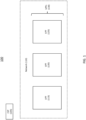
- FIG. 1 is a block diagram of a communication system, namely system 100, that shares among its UPFs, APN total bandwidth limits.
- System 100 includes a CSP 105, a network 110, and UPFs 115, 120 and 125.
- UPFs 115, 120 and 125 are collectively referred to as UPFs 130.
- Network 110 is a data network.
- CSP 105 maintains network 110.
- UPFs 130 perform operations in network 110, as described below.
- network 110 may contain any number of UPFs.
- FIG. 2 is a block diagram of an example in which UPFs 130 are serving APNs 205 and 210, and in which user equipment (UEs) 215, 220, 225, 230, 235, 240, 245 and 250 are accessing data services at various bandwidth speeds measured in Mbps.
- UEs user equipment
- APN 205 is being served by UPF 115, UPF 120 and UPF 125.
- An example of APN 205 could be an enterprise called XYZ Corp that has a contract with CSP 105 to use a maximum of X Mbps amongst all of XYZ Corp's users (i.e., delivery agents of the group).
- the connected users of XYZ Corp are (UEs) 215, 220, 225, 230, 235, 240 and 245.
- UPF 115, through APN 205, is serving UE 215, UE 220 and UE 225.
- each of UE 215, UE 220 and UE 225 is accessing data services through APN 205 connected through UPF 115.
- UE 215 is accessing at a speed of 1 Mbps, UE 220 at a speed of 2 Mbps, and UE 225 at a speed of 1 Mbps.
- UPF 120 through APN 205, is serving UE 230 and UE 235. Both of UE 230 and 235 are accessing at a speed of 2 Mbps.
- UPF 125 through APN 205, is serving UE 240 and UE 245. Both of UE 240 and UE 245 are accessing at a speed of 1 Mbps.
- UPF 125 through APN 210, is serving UE 250, and UE 250 is accessing at a speed of 1 Mbps, represented by reference 270.
- FIG. 3 is a signal flow diagram of a process of sharing of total bandwidth consumption per APN/DNN among UPFs 130 for the example in FIG. 2 .
- UPFs 130 Using any leader election method, one of UPFs 130 would be nominated as a delegator. Assume that UPF 120 is nominated as the delegator. In a case of a failure of the delegator, an alternate delegator, e.g., UPF 115, shall be elected.
- UPFs 130 communicate with one another by way of signaling messages through network 110.
- UPF 115 shares its current bandwidth consumption for APN 205, to UPF 120, i.e., the delegator.
- UPF 115's current bandwidth consumption for APN 205 is 4 Mbps, i.e., reference 255.
- UPF 125 shares its current bandwidth consumption for APN 205, to UPF 120, i.e., the delegator.
- UPF 125's current bandwidth consumption for APN 205 is 2 Mbps, i.e., reference 265.
- UPF 120 shares current bandwidth consumption for APN 205 of UPF 120 and UPF 125 individually, to UPF 115.
- current bandwidth consumption for APN 205 of UPF 120 and UPF 125 is 4 Mbps (reference 260) and 2 Mbps (reference 265), respectively.
- UPF 120 shares current bandwidth consumption for APN 205 of UPF 120 and UPF 115 individually, to UPF 125.
- current bandwidth consumption for APN 205 of UPF 120 and UPF 115 is 4 Mbps (reference 260) and 4 Mbps (reference 255), respectively.
- UPF 120 has shared the current bandwidth consumption for APN 205 of UPF 120 and UPF 115 to UPF 125, and also shared the current bandwidth consumption of UPF 120 and UPF 125 to UPF 115.
- UPF 120 i.e., the delegator, has shared current bandwidth consumption for APN 205 of all the UPFs to each of the peer UPFs.
- all UPFs 130 are aware of the total current bandwidth consumption for APN 205, (i.e., reference 255 + reference 260 + reference 265). More generally, all UPFs 130 will be made aware of the total current bandwidth consumption for APN 205 irrespective of how many UPFs are serving APN 205.
- Operations 305, 310, 315 and 320 are repeated periodically, every calendar 5 seconds (for example, 0 th second of the day, 5 th second of the day, 10 th second of the day, 15 th second of the day and so on till 86,400 th second of the day and so on next day) so that all the UPFs serving a specific APN aware of the current total bandwidth consumption for that APN.
- operations 305, 310, 315 and 320 are repeated periodically, e.g., every 5 seconds. Periodicity can be adjusted based on the implementation dependency and the accuracy needed.
- Each of UPFs 130 is aware of the total bandwidth consumption for APN 205 across all UPFs 130, and can compare the total bandwidth consumption to the bandwidth limit, i.e., a threshold value. If the bandwidth limit is exceeded, each of UPFs 130 shall carry out a configured action, i.e., a programmed action, such as a drop of additional packets, for example. Thus, UPFs 130, collectively, can enforce a configured maximum bandwidth limit for APN 205.
- a configured action i.e., a programmed action, such as a drop of additional packets, for example.
- the sharing of bandwidth consumption of each UPF with lesser number of signaling message exchanges across all the UPFs serving an APN enables the UPFs to implement APN/DNN total bandwidth per APN/DNN across the CSP's UPFs.
- This method causes less signaling as the elected delegator carries out broadcast to all other UPFs rather than each UPF talking to every other UPF in terms of receiving and sending each of the bandwidth consumption.
- Each of UPF 115, UPF 120 and UPF 125 is implemented in a device that includes electronic circuitry that performs operations to execute methods or processes described herein.
- the circuity may be implemented with any or all of (a) discrete electronic components, (b) firmware, or (c) a programmable circuit that includes a processor and a memory.
- a processor is an electronic device configured of logic circuitry that responds to and executes instructions.
- a memory is a tangible, non-transitory, computer-readable storage device encoded with a computer program.
- the memory stores data and instructions, i.e., program code, that are readable and executable by the processor for controlling operations of the processor.
- the memory may be implemented in a random-access memory (RAM), a hard drive, a read only memory (ROM), or a combination thereof.
- Such a processor and memory may be implemented in a computer.
- the computer can be a standalone device or coupled to other devices in a distributed processing system.
- the program code may be configured on a storage device for subsequent loading into the memory.
- a storage device is a tangible, non-transitory, computer-readable storage device, and examples include (a) a compact disk, (b) a magnetic tape, (c) a read only memory, (d) an optical storage medium, (e) a hard drive, (f) a memory unit consisting of multiple parallel hard drives, (g) a universal serial bus (USB) flash drive, (h) a random-access memory, and (i) an electronic storage device coupled to devices upon which UPF 115, UPF 120 and UPF 125 are implemented, via network 110.
- USB universal serial bus
- the program code may be configured in one or more modules.
- module is used herein to denote a functional operation that may be embodied either as a stand-alone component or as an integrated configuration of a plurality of subordinate components. Thus, a module may be implemented as a single module or as a plurality of sub-ordinate modules that operate in cooperation with one another.
- network 110 may contain any number of UPFs, and there may be any number of APNs and UEs. Moreover, in a case of multiple APNs, each APN can have its own bandwidth limit.
- the present disclosure relates to any 3GPP release versions or generations, and relates more particularly to accessing of data by various users using an Access Point Name (APN) or Data Network Name (DNN) in the data networks.
- APN Access Point Name
- DNN Data Network Name
- This disclosure inherently covers fixed broadband and Wi-Fi Access networks as well.
Landscapes
- Engineering & Computer Science (AREA)
- Computer Networks & Wireless Communication (AREA)
- Signal Processing (AREA)
- Data Exchanges In Wide-Area Networks (AREA)
Abstract
Description
- The present disclosure relates to telecommunications systems, and more particularly, accessing of data by users of an Access Point Name (APN) or Data Network Name (DNN) in a data network.
- The approaches described in this section are approaches that could be pursued, but not necessarily approaches that have been previously conceived or pursued. Therefore, the approaches described in this section may not be prior art to the claims in this application and are not admitted prior art by inclusion in this section.
- A User Plane Function (UPF) performs operations such as packet routing and forwarding, packet inspection, maintaining an internet protocol (IP) session, policy enforcement, and quality of service (QoS) handling.
- In a user plane infrastructure, there may be a requirement to implement bandwidth limits amongst a group of users. For example, a retail chain enterprise may wish to limit a total bandwidth of all employees collectively to not exceed a limit of X megabits per second (Mbps). In another example, a communication service provider (CSP) may set up a telecom infrastructure spread across different regions, which also consists of multiple UPFs that enable many private players/enterprises to use services and use a maximum bandwidth of X Mbps amongst all its users connected via the multiple UPFs.
- A grouping of users and identification of enterprises is done using the concept of APN (Access Point Name) or DNN (Data Network Name).
- To enable the CSP to implement maximum bandwidth limits of a group (APN/DNN) where there are multiple UPFs serving one group (APN/DNN), each UPF in the infrastructure needs to be aware of the current maximum bandwidth values of all the other UPFs of a group (APN/DNN) to be able to limit the bandwidth of the group to one configured value. For example, the CSP may configure the maximum bandwidth access of all users accessing data using the APN "XYZ Corp" amongst all the UPFs should be under 100 Mbps, which means the total of bandwidth across all the UPFs amongst all users of the APN should be under 100 Mbps. Enabling each UPF in the infrastructure aware of the total bandwidth consumption across all UPFs for a group (APN/DNN) shall enrich UPF to make a decision on how much more bandwidth is left over to be allowed based on the maximum bandwidth configured.
- When such a use case as mentioned above is needed to be implemented by a CSP, and if access to the network for a particular group (APN / DNN) is handled by different UPFs available in the network, each UPF would be agnostic on what is the current bandwidth utilization of that group in other multiple UPFs. This situation would push the CSP to implement only one UPF for a group, thus restricting flexibility, and in scenarios where multiple UPFs are needed to be implemented in the network, this use case would not be feasible to be deployed by the CSP.
- The present document discloses a solution to share the bandwidth occupancy of each UPF instance to all the UPF nodes in a network serving a specific group (APN/DNN). This enables all UPF instances to be aware of the current total bandwidth consumed by all users in a particular APN/DNN across all UPF instances, and act accordingly. Acting accordingly may include dropping packets, prioritizing packets, etc. A CSP may choose to implement this feature or use case to all the groups (APN/DNNs) or only to certain APN/DNNs. Hence only for the needed APN/DNNs, this bandwidth utilization information exchange can be implemented at multiple UPFs serving those corresponding APN/DNNs.
- The solution is not only applicable to APN/DNN-based groupings, but applicable to any alternate nomenclatures used to group the access. The solution is a UPF self-contained proposal, and there is no dependency on a control plane (CP) function to implement the same.
- There is provided a method for sharing bandwidth consumption information in a communication system having a first UPF that serves an APN, a second UPF that serves the APN, and a third UPF that serves the APN. The method includes (a) receiving by the first UPF from the second UPF, information indicating a current bandwidth being consumed by the second UPF for the APN, (b) receiving by the first UPF from the third UPF, information indicating a current bandwidth being consumed by the third UPF for the APN, (c) sending from the first UPF to the second UPF, information indicating a current bandwidth being consumed by the first UPF for the APN and the current bandwidth being consumed by the third UPF for the APN, and (d) sending from the first UPF to the third UPF, information indicating the current bandwidth being consumed by the first UPF for the APN and the current bandwidth being consumed by the second UPF for the APN. Each of the first UPF, the second UPF and the third UPF is thus aware of a total current bandwidth being consumed by the first UPF, the second UPF and the third UPF for the APN.
-
-
FIG. 1 is a block diagram of a system that shares, among its UPFs, APN total bandwidth limits. -
FIG. 2 is a block diagram of an example in which UPFs are serving APNs, and in which user equipment are accessing data services at various bandwidth speeds, in the system ofFIG. 1 . -
FIG. 3 is a signal flow diagram of a process of sharing of total bandwidth per APN among UPFs for the example inFIG. 2 . - A component or a feature that is common to more than one drawing is indicated with the same reference number in each of the drawings.
-
FIG. 1 is a block diagram of a communication system, namelysystem 100, that shares among its UPFs, APN total bandwidth limits.System 100 includes a CSP 105, anetwork 110, and UPFs 115, 120 and 125. UPFs 115, 120 and 125 are collectively referred to as UPFs 130. - Network 110 is a data network. CSP 105 maintains
network 110. UPFs 130 perform operations innetwork 110, as described below. - Although
system 100 is shown as having three UPFs, namely UPFs, 115, 120 and 125, in practice,network 110 may contain any number of UPFs. -
FIG. 2 is a block diagram of an example in which UPFs 130 are servingAPNs - APN 205 is being served by UPF 115, UPF 120 and UPF 125. An example of APN 205 could be an enterprise called XYZ Corp that has a contract with CSP 105 to use a maximum of X Mbps amongst all of XYZ Corp's users (i.e., delivery agents of the group). In this example, the connected users of XYZ Corp are (UEs) 215, 220, 225, 230, 235, 240 and 245.
- UPF 115, through APN 205, is serving UE 215, UE 220 and UE 225. In other words, each of UE 215, UE 220 and UE 225 is accessing data services through APN 205 connected through UPF 115. At a given instance of time, UE 215 is accessing at a speed of 1 Mbps, UE 220 at a speed of 2 Mbps, and UE 225 at a speed of 1 Mbps.
- UPF 120, through APN 205, is serving UE 230 and UE 235. Both of UE 230 and 235 are accessing at a speed of 2 Mbps.
- UPF 125, through APN 205, is serving UE 240 and UE 245. Both of UE 240 and UE 245 are accessing at a speed of 1 Mbps.
- Thus, through APN 205:
- (a) UPF 115 is serving a total bandwidth of 4 Mbps, represented by
reference 255; - (b) UPF 120 is serving a total bandwidth of 4 Mbps, represented by
reference 260; and - (c) UPF 125 is serving a total bandwidth of 2 Mbps, represented by
reference 265. - Additionally, UPF 125, through APN 210, is serving UE 250, and UE 250 is accessing at a speed of 1 Mbps, represented by
reference 270. -
FIG. 3 is a signal flow diagram of a process of sharing of total bandwidth consumption per APN/DNN amongUPFs 130 for the example inFIG. 2 . - Using any leader election method, one of UPFs 130 would be nominated as a delegator. Assume that UPF 120 is nominated as the delegator. In a case of a failure of the delegator, an alternate delegator, e.g., UPF 115, shall be elected.
- UPFs 130 communicate with one another by way of signaling messages through
network 110. - In
operation 305, UPF 115 shares its current bandwidth consumption for APN 205, to UPF 120, i.e., the delegator. In the present example, UPF 115's current bandwidth consumption for APN 205 is 4 Mbps, i.e.,reference 255. - In
operation 310, UPF 125 shares its current bandwidth consumption for APN 205, to UPF 120, i.e., the delegator. In the present example,UPF 125's current bandwidth consumption forAPN 205 is 2 Mbps, i.e.,reference 265. - In
operation 315,UPF 120 shares current bandwidth consumption forAPN 205 ofUPF 120 andUPF 125 individually, toUPF 115. In the present example, current bandwidth consumption forAPN 205 ofUPF 120 andUPF 125 is 4 Mbps (reference 260) and 2 Mbps (reference 265), respectively. - In
operation 320,UPF 120 shares current bandwidth consumption forAPN 205 ofUPF 120 andUPF 115 individually, toUPF 125. In the present example, current bandwidth consumption forAPN 205 ofUPF 120 andUPF 115 is 4 Mbps (reference 260) and 4 Mbps (reference 255), respectively. - In the present example,
UPF 120 has shared the current bandwidth consumption forAPN 205 ofUPF 120 andUPF 115 toUPF 125, and also shared the current bandwidth consumption ofUPF 120 andUPF 125 toUPF 115. Thus,UPF 120, i.e., the delegator, has shared current bandwidth consumption forAPN 205 of all the UPFs to each of the peer UPFs. - As shown at
block 325, allUPFs 130 are aware of the total current bandwidth consumption forAPN 205, (i.e.,reference 255 +reference 260 + reference 265). More generally, allUPFs 130 will be made aware of the total current bandwidth consumption forAPN 205 irrespective of how many UPFs are servingAPN 205. -
Operations operations - Each of
UPFs 130 is aware of the total bandwidth consumption forAPN 205 across allUPFs 130, and can compare the total bandwidth consumption to the bandwidth limit, i.e., a threshold value. If the bandwidth limit is exceeded, each ofUPFs 130 shall carry out a configured action, i.e., a programmed action, such as a drop of additional packets, for example. Thus,UPFs 130, collectively, can enforce a configured maximum bandwidth limit forAPN 205. - As illustrated in
FIG. 3 , the sharing of bandwidth consumption of each UPF with lesser number of signaling message exchanges across all the UPFs serving an APN enables the UPFs to implement APN/DNN total bandwidth per APN/DNN across the CSP's UPFs. This method causes less signaling as the elected delegator carries out broadcast to all other UPFs rather than each UPF talking to every other UPF in terms of receiving and sending each of the bandwidth consumption. - Each of
UPF 115,UPF 120 andUPF 125 is implemented in a device that includes electronic circuitry that performs operations to execute methods or processes described herein. The circuity may be implemented with any or all of (a) discrete electronic components, (b) firmware, or (c) a programmable circuit that includes a processor and a memory. Such a processor is an electronic device configured of logic circuitry that responds to and executes instructions. Such a memory is a tangible, non-transitory, computer-readable storage device encoded with a computer program. In this regard, the memory stores data and instructions, i.e., program code, that are readable and executable by the processor for controlling operations of the processor. The memory may be implemented in a random-access memory (RAM), a hard drive, a read only memory (ROM), or a combination thereof. - Such a processor and memory may be implemented in a computer. The computer can be a standalone device or coupled to other devices in a distributed processing system.
- Additionally, the program code may be configured on a storage device for subsequent loading into the memory. Such a storage device is a tangible, non-transitory, computer-readable storage device, and examples include (a) a compact disk, (b) a magnetic tape, (c) a read only memory, (d) an optical storage medium, (e) a hard drive, (f) a memory unit consisting of multiple parallel hard drives, (g) a universal serial bus (USB) flash drive, (h) a random-access memory, and (i) an electronic storage device coupled to devices upon which
UPF 115,UPF 120 andUPF 125 are implemented, vianetwork 110. - The program code may be configured in one or more modules. The term "module" is used herein to denote a functional operation that may be embodied either as a stand-alone component or as an integrated configuration of a plurality of subordinate components. Thus, a module may be implemented as a single module or as a plurality of sub-ordinate modules that operate in cooperation with one another.
- Although
network 100 is shown as having three UPFs, in practice,network 110 may contain any number of UPFs, and there may be any number of APNs and UEs. Moreover, in a case of multiple APNs, each APN can have its own bandwidth limit. - The present disclosure relates to any 3GPP release versions or generations, and relates more particularly to accessing of data by various users using an Access Point Name (APN) or Data Network Name (DNN) in the data networks. This disclosure inherently covers fixed broadband and Wi-Fi Access networks as well.
- The techniques described herein are exemplary and should not be construed as implying any limitation on the present disclosure. Various alternatives, combinations and modifications could be devised by those skilled in the art. For example, operations associated with the processes described herein can be performed in any order, unless otherwise specified or dictated by the operations themselves. The present disclosure is intended to embrace all such alternatives, modifications and variances that fall within the scope of the appended claims.
- The terms "comprises" or "comprising" are to be interpreted as specifying the presence of the stated features, integers, operations or components, but not precluding the presence of one or more other features, integers, operations or components or groups thereof. The terms "a" and "an" are indefinite articles, and as such, do not preclude embodiments having pluralities of articles.
Claims (18)
- A method for sharing bandwidth consumption information in a communication system having a first user plane function (UPF) that serves an access point name (APN), a second UPF that serves said APN, and a third UPF that serves said APN, wherein said method comprises:receiving by said first UPF from said second UPF, information indicating a current bandwidth being consumed by said second UPF for said APN;receiving by said first UPF from said third UPF, information indicating a current bandwidth being consumed by said third UPF for said APN;sending from said first UPF to said second UPF, information indicating a current bandwidth being consumed by said first UPF for said APN and said current bandwidth being consumed by said third UPF for said APN; andsending from said first UPF to said third UPF, information indicating said current bandwidth being consumed by said first UPF for said APN and said current bandwidth being consumed by said second UPF for said APN,whereby each of said first UPF, said second UPF and said third UPF is thus aware of a total current bandwidth being consumed by said first UPF, said second UPF and said third UPF for said APN.
- The method of claim 1, wherein said first UPF performs further operations of:comparing said total current bandwidth to a threshold value; andperforming a programmed action in response to said total current bandwidth exceeding said threshold value.
- The method of claim 2, wherein said programmed action is an action selected from the group consisting of dropping packets and prioritizing packets.
- The method of claim 1, wherein said second UPF performs further operations of:comparing said total current bandwidth to a threshold value; andperforming a programmed action in response to said total current bandwidth exceeding said threshold value.
- The method of claim 4, wherein said programmed action is an action selected from the group consisting of dropping packets and prioritizing packets.
- The method of claim 1, wherein at least one of:a) said method is executed periodically; andb) i) said first UPF is nominated as a delegator to perform said method, and ii) said second UPF is elected as said delegator in response to a failure of said first UPF.
- A communication system, comprising:a first user plane function (UPF) that serves an access point name (APN), a second UPF that serves said APN, and a third UPF that serves said APN,wherein said first UPF performs operations of:receiving from said second UPF, information indicating a current bandwidth being consumed by said second UPF for said APN;receiving from said third UPF, information indicating a current bandwidth being consumed by said third UPF for said APN;sending to said second UPF, information indicating a current bandwidth being consumed by said first UPF for said APN and said current bandwidth being consumed by said third UPF for said APN; andsending to said third UPF, information indicating said current bandwidth being consumed by said first UPF for said APN and said current bandwidth being consumed by said second UPF for said APN,whereby each of said first UPF, said second UPF and said third UPF is thus aware of a total current bandwidth being consumed by said first UPF, said second UPF and said third UPF for said APN.
- The communication system of claim 7, wherein said first UPF performs further operations of:comparing said total current bandwidth to a threshold value; andperforming a programmed action in response to said total current bandwidth exceeding said threshold value.
- The communication system of claim 8, wherein said programmed action is an action selected from the group consisting of dropping packets and prioritizing packets.
- The communication system of claim 7, wherein said second UPF performs further actions of:comparing said total current bandwidth to a threshold value; andperforming a programmed action in response to said total current bandwidth exceeding said threshold value.
- The communication system of claim 10, wherein said programmed action is an action selected from the group consisting of dropping packets and prioritizing packets.
- The communication system of claim 7, wherein at least one of:a) said operations are executed periodically; andb) i) said first UPF is nominated as a delegator to perform said method, and ii) said second UPF is elected as said delegator in response to a failure of said first UPF.
- A storage device that is non-transitory, comprising instructions that are readable by a processor to cause said processor to perform operations of:receiving by a first user plane function (UPF) that serves an access point name (APN) from a second UPF that serves said APN, information indicating a current bandwidth being consumed by said second UPF for said APN;receiving by said first UPF from a third UPF that serves said APN, information indicating a current bandwidth being consumed by said third UPF for said APN;sending from said first UPF to said second UPF, information indicating a current bandwidth being consumed by said first UPF for said APN and said current bandwidth being consumed by said third UPF for said APN; andsending from said first UPF to said third UPF, information indicating said current bandwidth being consumed by said first UPF for said APN and said current bandwidth being consumed by said second UPF for said APN,whereby each of said first UPF, said second UPF and said third UPF is thus aware of a total current bandwidth being consumed by said first UPF, said second UPF and said third UPF for said APN.
- The storage device of claim 13, wherein said instructions cause said processor to perform further operations of:comparing said total current bandwidth to a threshold value; andperforming a programmed action in response to said total current bandwidth exceeding said threshold value.
- The storage device of claim 14, wherein said programmed action is an action selected from the group consisting of dropping packets and prioritizing packets.
- The storage device of claim 13, wherein said second UPF performs further operations of:comparing said total current bandwidth to a threshold value; andperforming a programmed action in response to said total current bandwidth exceeding said threshold value.
- The storage device of claim16, wherein said programmed action is an action selected from the group consisting of dropping packets and prioritizing packets.
- The storage device of claim 13, wherein at least one of:a) said operations are executed periodically; andb) i) said first UPF is nominated as a delegator to perform said method, and ii) said second UPF is elected as said delegator in response to a failure of said first UPF.
Applications Claiming Priority (2)
| Application Number | Priority Date | Filing Date | Title |
|---|---|---|---|
| IN202221059526 | 2022-10-18 | ||
| US18/485,727 US20240129244A1 (en) | 2022-10-18 | 2023-10-12 | Access point name total bandwidth limits |
Publications (2)
| Publication Number | Publication Date |
|---|---|
| EP4358488A1 true EP4358488A1 (en) | 2024-04-24 |
| EP4358488B1 EP4358488B1 (en) | 2025-09-03 |
Family
ID=88417103
Family Applications (1)
| Application Number | Title | Priority Date | Filing Date |
|---|---|---|---|
| EP23203993.3A Active EP4358488B1 (en) | 2022-10-18 | 2023-10-17 | Access point name total bandwidth limits |
Country Status (1)
| Country | Link |
|---|---|
| EP (1) | EP4358488B1 (en) |
Citations (4)
| Publication number | Priority date | Publication date | Assignee | Title |
|---|---|---|---|---|
| US20160112896A1 (en) * | 2013-01-11 | 2016-04-21 | Interdigital Patent Holdings Inc. | User-plane congestion management |
| US20190253917A1 (en) * | 2018-02-15 | 2019-08-15 | Huawei Technologies Co., Ltd. | Tracking qos violated events |
| US20220191737A1 (en) * | 2020-12-10 | 2022-06-16 | Verizon Patent And Licensing Inc. | Systems and methods for load control of a user device during network congestion |
| WO2022165235A1 (en) * | 2021-01-28 | 2022-08-04 | Ofinno, Llc | Uplink data indication |
-
2023
- 2023-10-17 EP EP23203993.3A patent/EP4358488B1/en active Active
Patent Citations (4)
| Publication number | Priority date | Publication date | Assignee | Title |
|---|---|---|---|---|
| US20160112896A1 (en) * | 2013-01-11 | 2016-04-21 | Interdigital Patent Holdings Inc. | User-plane congestion management |
| US20190253917A1 (en) * | 2018-02-15 | 2019-08-15 | Huawei Technologies Co., Ltd. | Tracking qos violated events |
| US20220191737A1 (en) * | 2020-12-10 | 2022-06-16 | Verizon Patent And Licensing Inc. | Systems and methods for load control of a user device during network congestion |
| WO2022165235A1 (en) * | 2021-01-28 | 2022-08-04 | Ofinno, Llc | Uplink data indication |
Also Published As
| Publication number | Publication date |
|---|---|
| EP4358488B1 (en) | 2025-09-03 |
Similar Documents
| Publication | Publication Date | Title |
|---|---|---|
| US8989002B2 (en) | System and method for controlling threshold testing within a network | |
| JP4841674B2 (en) | Method and apparatus for controlling latency variation in a packet forwarding network | |
| CN114143378B (en) | Network optimization method, device, gateway equipment and storage medium | |
| CN114391250B (en) | Bandwidth management method and device, computer storage medium and chip | |
| US20150222413A1 (en) | Synchronization in Computer Network | |
| CN116566907A (en) | A network congestion control method and related device | |
| EP3651416A1 (en) | Generating automatic bandwidth adjustment policies per label-switched path | |
| US20150117234A1 (en) | Monitoring Link Quality Between Network Devices | |
| US8619589B2 (en) | System and method for removing test packets | |
| CN115604197B (en) | Time-sensitive network message scheduling method, device, equipment and storage medium | |
| CN112468403A (en) | Communication method and related equipment thereof | |
| CN111884875A (en) | Offline device determination method and device | |
| US20190238595A1 (en) | Voice Call Controller | |
| EP3402280A1 (en) | Method and device for transmitting control signalling | |
| EP3531638A1 (en) | Handling of congestion for fronthaul traffic | |
| EP4358488B1 (en) | Access point name total bandwidth limits | |
| US20240129244A1 (en) | Access point name total bandwidth limits | |
| CN109547287B (en) | Bandwidth testing method and device and storage medium | |
| CN112600712B (en) | Service quality scheduling method and device | |
| US11153214B2 (en) | In service flow capability update in guaranteed bandwidth multicast network | |
| CN117376258B (en) | A method for sending data stream and related device | |
| US20250023818A1 (en) | Method for transmitting a data stream in a communication network, method for processing a data stream, method for controlling the processing of a data stream, and corresponding devices, terminal apparatus, execution entity, control entity, system and computer programs | |
| CN105704057B (en) | The method and apparatus for determining the type of service of burst port congestion packet loss | |
| US10270701B2 (en) | Management node, terminal, communication system, communication method, and program storage medium | |
| CN116032819A (en) | Equivalent load sharing method, device, network equipment and storage medium |
Legal Events
| Date | Code | Title | Description |
|---|---|---|---|
| PUAI | Public reference made under article 153(3) epc to a published international application that has entered the european phase |
Free format text: ORIGINAL CODE: 0009012 |
|
| STAA | Information on the status of an ep patent application or granted ep patent |
Free format text: STATUS: REQUEST FOR EXAMINATION WAS MADE |
|
| 17P | Request for examination filed |
Effective date: 20231017 |
|
| AK | Designated contracting states |
Kind code of ref document: A1 Designated state(s): AL AT BE BG CH CY CZ DE DK EE ES FI FR GB GR HR HU IE IS IT LI LT LU LV MC ME MK MT NL NO PL PT RO RS SE SI SK SM TR |
|
| GRAP | Despatch of communication of intention to grant a patent |
Free format text: ORIGINAL CODE: EPIDOSNIGR1 |
|
| STAA | Information on the status of an ep patent application or granted ep patent |
Free format text: STATUS: GRANT OF PATENT IS INTENDED |
|
| RIC1 | Information provided on ipc code assigned before grant |
Ipc: H04L 47/24 20220101ALN20250320BHEP Ipc: H04W 72/27 20230101ALI20250320BHEP Ipc: H04W 28/02 20090101ALI20250320BHEP Ipc: H04L 47/32 20220101AFI20250320BHEP |
|
| INTG | Intention to grant announced |
Effective date: 20250401 |
|
| RIC1 | Information provided on ipc code assigned before grant |
Ipc: H04L 47/24 20220101ALN20250321BHEP Ipc: H04W 72/27 20230101ALI20250321BHEP Ipc: H04W 28/02 20090101ALI20250321BHEP Ipc: H04L 47/32 20220101AFI20250321BHEP |
|
| GRAS | Grant fee paid |
Free format text: ORIGINAL CODE: EPIDOSNIGR3 |
|
| GRAA | (expected) grant |
Free format text: ORIGINAL CODE: 0009210 |
|
| STAA | Information on the status of an ep patent application or granted ep patent |
Free format text: STATUS: THE PATENT HAS BEEN GRANTED |
|
| AK | Designated contracting states |
Kind code of ref document: B1 Designated state(s): AL AT BE BG CH CY CZ DE DK EE ES FI FR GB GR HR HU IE IS IT LI LT LU LV MC ME MK MT NL NO PL PT RO RS SE SI SK SM TR |
|
| REG | Reference to a national code |
Ref country code: CH Ref legal event code: EP |
|
| P01 | Opt-out of the competence of the unified patent court (upc) registered |
Free format text: CASE NUMBER: UPC_APP_2798_4358488/2025 Effective date: 20250807 |
|
| REG | Reference to a national code |
Ref country code: DE Ref legal event code: R096 Ref document number: 602023006340 Country of ref document: DE |
|
| REG | Reference to a national code |
Ref country code: IE Ref legal event code: FG4D |
|
| REG | Reference to a national code |
Ref country code: NL Ref legal event code: MP Effective date: 20250903 |
|
| PG25 | Lapsed in a contracting state [announced via postgrant information from national office to epo] |
Ref country code: NO Free format text: LAPSE BECAUSE OF FAILURE TO SUBMIT A TRANSLATION OF THE DESCRIPTION OR TO PAY THE FEE WITHIN THE PRESCRIBED TIME-LIMIT Effective date: 20251203 |
|
| REG | Reference to a national code |
Ref country code: LT Ref legal event code: MG9D |
|
| PGFP | Annual fee paid to national office [announced via postgrant information from national office to epo] |
Ref country code: AT Payment date: 20260113 Year of fee payment: 3 |
|
| PG25 | Lapsed in a contracting state [announced via postgrant information from national office to epo] |
Ref country code: FI Free format text: LAPSE BECAUSE OF FAILURE TO SUBMIT A TRANSLATION OF THE DESCRIPTION OR TO PAY THE FEE WITHIN THE PRESCRIBED TIME-LIMIT Effective date: 20250903 |
|
| PG25 | Lapsed in a contracting state [announced via postgrant information from national office to epo] |
Ref country code: HR Free format text: LAPSE BECAUSE OF FAILURE TO SUBMIT A TRANSLATION OF THE DESCRIPTION OR TO PAY THE FEE WITHIN THE PRESCRIBED TIME-LIMIT Effective date: 20250903 |
|
| PG25 | Lapsed in a contracting state [announced via postgrant information from national office to epo] |
Ref country code: GR Free format text: LAPSE BECAUSE OF FAILURE TO SUBMIT A TRANSLATION OF THE DESCRIPTION OR TO PAY THE FEE WITHIN THE PRESCRIBED TIME-LIMIT Effective date: 20251204 |
|
| PG25 | Lapsed in a contracting state [announced via postgrant information from national office to epo] |
Ref country code: SE Free format text: LAPSE BECAUSE OF FAILURE TO SUBMIT A TRANSLATION OF THE DESCRIPTION OR TO PAY THE FEE WITHIN THE PRESCRIBED TIME-LIMIT Effective date: 20250903 |
|
| PG25 | Lapsed in a contracting state [announced via postgrant information from national office to epo] |
Ref country code: LV Free format text: LAPSE BECAUSE OF FAILURE TO SUBMIT A TRANSLATION OF THE DESCRIPTION OR TO PAY THE FEE WITHIN THE PRESCRIBED TIME-LIMIT Effective date: 20250903 |
|
| PG25 | Lapsed in a contracting state [announced via postgrant information from national office to epo] |
Ref country code: PL Free format text: LAPSE BECAUSE OF FAILURE TO SUBMIT A TRANSLATION OF THE DESCRIPTION OR TO PAY THE FEE WITHIN THE PRESCRIBED TIME-LIMIT Effective date: 20250903 Ref country code: BG Free format text: LAPSE BECAUSE OF FAILURE TO SUBMIT A TRANSLATION OF THE DESCRIPTION OR TO PAY THE FEE WITHIN THE PRESCRIBED TIME-LIMIT Effective date: 20250903 |
|
| PG25 | Lapsed in a contracting state [announced via postgrant information from national office to epo] |
Ref country code: RS Free format text: LAPSE BECAUSE OF FAILURE TO SUBMIT A TRANSLATION OF THE DESCRIPTION OR TO PAY THE FEE WITHIN THE PRESCRIBED TIME-LIMIT Effective date: 20251203 |
|
| PG25 | Lapsed in a contracting state [announced via postgrant information from national office to epo] |
Ref country code: ES Free format text: LAPSE BECAUSE OF FAILURE TO SUBMIT A TRANSLATION OF THE DESCRIPTION OR TO PAY THE FEE WITHIN THE PRESCRIBED TIME-LIMIT Effective date: 20250903 |
|
| REG | Reference to a national code |
Ref country code: AT Ref legal event code: MK05 Ref document number: 1834559 Country of ref document: AT Kind code of ref document: T Effective date: 20250903 |
|
| PG25 | Lapsed in a contracting state [announced via postgrant information from national office to epo] |
Ref country code: NL Free format text: LAPSE BECAUSE OF FAILURE TO SUBMIT A TRANSLATION OF THE DESCRIPTION OR TO PAY THE FEE WITHIN THE PRESCRIBED TIME-LIMIT Effective date: 20250903 |
|
| PG25 | Lapsed in a contracting state [announced via postgrant information from national office to epo] |
Ref country code: SM Free format text: LAPSE BECAUSE OF FAILURE TO SUBMIT A TRANSLATION OF THE DESCRIPTION OR TO PAY THE FEE WITHIN THE PRESCRIBED TIME-LIMIT Effective date: 20250903 |
|
| PGFP | Annual fee paid to national office [announced via postgrant information from national office to epo] |
Ref country code: DE Payment date: 20260128 Year of fee payment: 3 |
|
| PG25 | Lapsed in a contracting state [announced via postgrant information from national office to epo] |
Ref country code: AT Free format text: LAPSE BECAUSE OF FAILURE TO SUBMIT A TRANSLATION OF THE DESCRIPTION OR TO PAY THE FEE WITHIN THE PRESCRIBED TIME-LIMIT Effective date: 20250903 |
|
| PG25 | Lapsed in a contracting state [announced via postgrant information from national office to epo] |
Ref country code: RO Free format text: LAPSE BECAUSE OF FAILURE TO SUBMIT A TRANSLATION OF THE DESCRIPTION OR TO PAY THE FEE WITHIN THE PRESCRIBED TIME-LIMIT Effective date: 20250903 Ref country code: IT Free format text: LAPSE BECAUSE OF FAILURE TO SUBMIT A TRANSLATION OF THE DESCRIPTION OR TO PAY THE FEE WITHIN THE PRESCRIBED TIME-LIMIT Effective date: 20250903 |
|
| PG25 | Lapsed in a contracting state [announced via postgrant information from national office to epo] |
Ref country code: IS Free format text: LAPSE BECAUSE OF FAILURE TO SUBMIT A TRANSLATION OF THE DESCRIPTION OR TO PAY THE FEE WITHIN THE PRESCRIBED TIME-LIMIT Effective date: 20260103 |
|
| PG25 | Lapsed in a contracting state [announced via postgrant information from national office to epo] |
Ref country code: PT Free format text: LAPSE BECAUSE OF FAILURE TO SUBMIT A TRANSLATION OF THE DESCRIPTION OR TO PAY THE FEE WITHIN THE PRESCRIBED TIME-LIMIT Effective date: 20260105 Ref country code: CZ Free format text: LAPSE BECAUSE OF FAILURE TO SUBMIT A TRANSLATION OF THE DESCRIPTION OR TO PAY THE FEE WITHIN THE PRESCRIBED TIME-LIMIT Effective date: 20250903 |
|
| PG25 | Lapsed in a contracting state [announced via postgrant information from national office to epo] |
Ref country code: EE Free format text: LAPSE BECAUSE OF FAILURE TO SUBMIT A TRANSLATION OF THE DESCRIPTION OR TO PAY THE FEE WITHIN THE PRESCRIBED TIME-LIMIT Effective date: 20250903 Ref country code: SK Free format text: LAPSE BECAUSE OF FAILURE TO SUBMIT A TRANSLATION OF THE DESCRIPTION OR TO PAY THE FEE WITHIN THE PRESCRIBED TIME-LIMIT Effective date: 20250903 |
|
| REG | Reference to a national code |
Ref country code: DE Ref legal event code: R097 Ref document number: 602023006340 Country of ref document: DE |
|
| PG25 | Lapsed in a contracting state [announced via postgrant information from national office to epo] |
Ref country code: LU Free format text: LAPSE BECAUSE OF NON-PAYMENT OF DUE FEES Effective date: 20251017 |
|
| REG | Reference to a national code |
Ref country code: BE Ref legal event code: MM Effective date: 20251031 |
|
| PG25 | Lapsed in a contracting state [announced via postgrant information from national office to epo] |
Ref country code: MC Free format text: LAPSE BECAUSE OF FAILURE TO SUBMIT A TRANSLATION OF THE DESCRIPTION OR TO PAY THE FEE WITHIN THE PRESCRIBED TIME-LIMIT Effective date: 20250903 Ref country code: LT Free format text: LAPSE BECAUSE OF FAILURE TO SUBMIT A TRANSLATION OF THE DESCRIPTION OR TO PAY THE FEE WITHIN THE PRESCRIBED TIME-LIMIT Effective date: 20250903 |
|
| PG25 | Lapsed in a contracting state [announced via postgrant information from national office to epo] |
Ref country code: DK Free format text: LAPSE BECAUSE OF FAILURE TO SUBMIT A TRANSLATION OF THE DESCRIPTION OR TO PAY THE FEE WITHIN THE PRESCRIBED TIME-LIMIT Effective date: 20250903 |
|
| PLBE | No opposition filed within time limit |
Free format text: ORIGINAL CODE: 0009261 |
|
| STAA | Information on the status of an ep patent application or granted ep patent |
Free format text: STATUS: NO OPPOSITION FILED WITHIN TIME LIMIT |
|
| REG | Reference to a national code |
Ref country code: CH Ref legal event code: L10 Free format text: ST27 STATUS EVENT CODE: U-0-0-L10-L00 (AS PROVIDED BY THE NATIONAL OFFICE) Effective date: 20260715 |
|
| PG25 | Lapsed in a contracting state [announced via postgrant information from national office to epo] |
Ref country code: BE Free format text: LAPSE BECAUSE OF NON-PAYMENT OF DUE FEES Effective date: 20251031 |
|
| PG25 | Lapsed in a contracting state [announced via postgrant information from national office to epo] |
Ref country code: FR Free format text: LAPSE BECAUSE OF NON-PAYMENT OF DUE FEES Effective date: 20251103 |
|
| 26N | No opposition filed |
Effective date: 20260604 |