EP4358405A1 - Aircraft solid state power controller and method of operating an aircraft solid state power controller - Google Patents
Aircraft solid state power controller and method of operating an aircraft solid state power controller Download PDFInfo
- Publication number
- EP4358405A1 EP4358405A1 EP22202131.3A EP22202131A EP4358405A1 EP 4358405 A1 EP4358405 A1 EP 4358405A1 EP 22202131 A EP22202131 A EP 22202131A EP 4358405 A1 EP4358405 A1 EP 4358405A1
- Authority
- EP
- European Patent Office
- Prior art keywords
- electric
- switching device
- node
- power supply
- solid state
- Prior art date
- Legal status (The legal status is an assumption and is not a legal conclusion. Google has not performed a legal analysis and makes no representation as to the accuracy of the status listed.)
- Pending
Links
Images


Classifications
-
- H—ELECTRICITY
- H02—GENERATION; CONVERSION OR DISTRIBUTION OF ELECTRIC POWER
- H02H—EMERGENCY PROTECTIVE CIRCUIT ARRANGEMENTS
- H02H3/00—Emergency protective circuit arrangements for automatic disconnection directly responsive to an undesired change from normal electric working condition with or without subsequent reconnection ; integrated protection
- H02H3/26—Emergency protective circuit arrangements for automatic disconnection directly responsive to an undesired change from normal electric working condition with or without subsequent reconnection ; integrated protection responsive to difference between voltages or between currents; responsive to phase angle between voltages or between currents
- H02H3/28—Emergency protective circuit arrangements for automatic disconnection directly responsive to an undesired change from normal electric working condition with or without subsequent reconnection ; integrated protection responsive to difference between voltages or between currents; responsive to phase angle between voltages or between currents involving comparison of the voltage or current values at two spaced portions of a single system, e.g. at opposite ends of one line, at input and output of apparatus
-
- H—ELECTRICITY
- H03—ELECTRONIC CIRCUITRY
- H03K—PULSE TECHNIQUE
- H03K17/00—Electronic switching or gating, i.e. not by contact-making and –breaking
- H03K17/18—Modifications for indicating state of switch
-
- H—ELECTRICITY
- H02—GENERATION; CONVERSION OR DISTRIBUTION OF ELECTRIC POWER
- H02H—EMERGENCY PROTECTIVE CIRCUIT ARRANGEMENTS
- H02H3/00—Emergency protective circuit arrangements for automatic disconnection directly responsive to an undesired change from normal electric working condition with or without subsequent reconnection ; integrated protection
- H02H3/02—Details
- H02H3/04—Details with warning or supervision in addition to disconnection, e.g. for indicating that protective apparatus has functioned
- H02H3/044—Checking correct functioning of protective arrangements, e.g. by simulating a fault
-
- H—ELECTRICITY
- H02—GENERATION; CONVERSION OR DISTRIBUTION OF ELECTRIC POWER
- H02J—ELECTRIC POWER NETWORKS; CIRCUIT ARRANGEMENTS OR SYSTEMS FOR SUPPLYING OR DISTRIBUTING ELECTRIC POWER; SYSTEMS FOR STORING ELECTRIC ENERGY
- H02J1/00—Circuit arrangements for DC mains or DC distribution networks
-
- G—PHYSICS
- G01—MEASURING; TESTING
- G01R—MEASURING ELECTRIC VARIABLES; MEASURING MAGNETIC VARIABLES
- G01R31/00—Arrangements for testing electric properties; Arrangements for locating electric faults; Arrangements for electrical testing characterised by what is being tested not provided for elsewhere
- G01R31/327—Testing of circuit interrupters, switches or circuit-breakers
- G01R31/3277—Testing of circuit interrupters, switches or circuit-breakers of low voltage devices, e.g. domestic or industrial devices, such as motor protections, relays, rotation switches
-
- H—ELECTRICITY
- H02—GENERATION; CONVERSION OR DISTRIBUTION OF ELECTRIC POWER
- H02J—ELECTRIC POWER NETWORKS; CIRCUIT ARRANGEMENTS OR SYSTEMS FOR SUPPLYING OR DISTRIBUTING ELECTRIC POWER; SYSTEMS FOR STORING ELECTRIC ENERGY
- H02J2105/00—Networks for supplying or distributing electric power characterised by their spatial reach or by the load
- H02J2105/30—Networks for supplying or distributing electric power characterised by their spatial reach or by the load the load networks being external to vehicles, i.e. exchanging power with vehicles
- H02J2105/32—Networks for supplying or distributing electric power characterised by their spatial reach or by the load the load networks being external to vehicles, i.e. exchanging power with vehicles for aircrafts
Definitions
- the invention is related to aircraft solid state power controller ("SSPC") for controlling the supply of electric power from an aircraft electric power supply to at least one electric load within an aircraft.
- SSPC aircraft solid state power controller
- the invention is further related to a method of operating such an aircraft solid state power controller.
- Modern aircraft usually comprise at least one aircraft solid state power controller (“SSPC") for controlling the supply of electric power from an aircraft electric power supply to at least one electric load.
- the at least one SSPC in particular includes at least one electric switching device, in particular at least one solid state switching device, which is configured for selectively switching the electric power supplied to the at least one electric load.
- the functionality of the at least one electric switching device is to be regularly checked.
- the at least one electric switching device is in particular switchable between an on-state, in which the at least one electric switching device provides a low-resistive electric connection between the feed node and the load node; and a high-resistive off-state, in which the at least one electric switching device electrically isolates the at least one load node from the feed node.
- the SSPC further comprises a secondary electric power supply, which is independent from the primary electric power supply.
- the secondary electric power supply is configured for applying a test voltage between the feed node and the load node of the SSPC in order to allow for determining the switching state of the at least one electric switching device by detecting a voltage drop between the feed node and the load node.
- the switching state of the at least one electric switching device can be detected independent of whether the primary electric power supply is connected to the feed node.
- Exemplary embodiments of the invention also include an aircraft, such as an airplane or a helicopter, comprising at least one electric power supply and at least one SSPC according to an exemplary embodiment of the invention.
- an aircraft such as an airplane or a helicopter, comprising at least one electric power supply and at least one SSPC according to an exemplary embodiment of the invention.
- Exemplary embodiments of the invention further include a method of operating an SSPC, wherein the SSPC comprises a feed node, which is to be electrically connected to a primary electric power supply; aload node, which is to be electrically connected to at least one electric load; and at least one electric switching device, in particular at least one solid state switching device, which is arranged between the feed node and the load node for switching the supply of electric power from the feed node to the load node; wherein the method comprises: selectively switching the at least one electric switching device between an on-state, in which the at least one electric switching device provides a low-resistive electric connection between the feed node and the load node so that the primary power supply is electrically connected with the electric load; and a high-resistive off-state, in which the at least one electric switching device electrically isolates the load node from the feed node; applying a test voltage between the feed node and the load node of the SSPC; wherein the test voltage is provided by a secondary electric power
- the switching state of the at least one electric switching device may be detected independently of a feed voltage supplied by the primary electric power supply.
- the detection of the switching state of the at least one electric switching device is not deteriorated by the electric load.
- the switching state of the at least one electric switching device may be monitored very reliably, and the operational safety of the SSPC may be enhanced.
- a signal indicative of the correct operation, or the switching state, of the electric switching device may be provided independent of other operations of the SSPC, particularly independent of the primary electric power supply.
- the at least one electric switching device may be a solid state switching device, in particular a transistor such as a bipolar transistor, an insulated-gate bipolar transistor (IGBT), or a field-effect transistor (FET), in particular a metal-oxide-semiconductor field-effect transistor (MOSFET).
- a transistor such as a bipolar transistor, an insulated-gate bipolar transistor (IGBT), or a field-effect transistor (FET), in particular a metal-oxide-semiconductor field-effect transistor (MOSFET).
- IGBT insulated-gate bipolar transistor
- FET field-effect transistor
- MOSFET metal-oxide-semiconductor field-effect transistor
- Particular embodiments may further include one, or a plurality, of the following optional features. These optional features may be applied separately, or in combination with each other, unless specified otherwise.
- the secondary electric power supply is galvanically isolated from the primary electric power supply in order to provide an electric separation between the primary electric power supply and the secondary electric power supply. Such an electric separation allows preventing any undesirable interactions between the primary electric power supply and the secondary electric power supply.
- the SSPC comprises further electric power supplies, which are provided for supplying electric power to further electric components of the SSPC, and the secondary electric power supply is galvanically isolated from, these additional power supplies as well.
- the SSPC comprises an integrated circuit including an isolated DC power supply, which is employed as the secondary power supply.
- the integrated circuit may, for example, include a controller for controlling the operation of the SSPC.
- Providing the secondary power supply as part of an integrated circuit of the SSPC is a very efficient way of providing the secondary power supply.
- the secondary power supply may be provided as a separate secondary power supply. This allows for a clear separation between the SSPC and/or electric components of the SSPC and the secondary power supply.
- the secondary power supply may be provided as a shared secondary power supply for applying the test voltage between the feed node and the load node and for providing also other voltages, for example a voltage for operating a controller of the SSPC and/or a control voltage, which is to be applied to a control terminal of the at least one electric switching device.
- a shared secondary power supply for applying the test voltage between the feed node and the load node and for providing also other voltages, for example a voltage for operating a controller of the SSPC and/or a control voltage, which is to be applied to a control terminal of the at least one electric switching device.
- the integrated circuit including the power supply is a DC/DC power chip, in particular an ADUM 5241 chip or an ADUM 5242 chip.
- the at least one electric switching device comprises a control terminal for receiving a control voltage for controlling/switching the at least one electric switching device at least between a low-resistive on-state and a high-resistive off-state.
- the SSPC may further comprise an electric switching device controller, which is configured applying the control voltage to the control terminal of the at least one electric switching device for selectively switching the at least one electric switching device at least between the on-state and the off-state.
- the secondary power supply is configured for providing electric power for supplying the control voltage to the control terminal of the at least one electric switching device. This allows for a very efficient use of the secondary power supply.
- the electric switching device comprises a first terminal connected to the feed node and a second terminal connected to the load node, and the secondary power supply is referenced to the second terminal of the at least one electric switching device, or to a reference point between the second terminal and the load node of the solid state power controller, in order to apply a defined electric test voltage between the feed node and the load node of the at least one electric switching device.
- the SSPC further comprises a test voltage sensor, which is configured for detecting a voltage drop which allows determining the switching state of the at least one electric switching device.
- the voltage sensor may in particular be configured for detecting the above mentioned voltage drop between the feed node and the load node of the solid state switching element when applying the test voltage V iso .
- such voltage drop between the feed node and the load node of the solid state switching element element when applying the test voltage V iso may be detected by connecting a test voltage measurement resistor in series with the solid state switching element and parallel to the load node and detecting a voltage drop across the test voltage resistor element when applying the test voltage V iso .
- the test voltage sensor is configured to deliver a signal indicating whether the at least one electric switching device is in its on-state or in its off-state.
- the test voltage sensor may in particular be configured for delivering a binary signal.
- the SSPC comprises a test voltage sensor, which is configured for detecting a voltage drop that allows determining the switching state of the at least one electric switching device, and a comparator, which is configured for comparing the voltage signal detected by the test voltage sensor with a reference voltage, and for providing a binary signal indicating the switching state of the at least one electric switching device based on the comparison.
- the status of the binary signal may depend on whether the voltage drop, as it is detected by the test voltage sensor, exceeds the predefined reference voltage or not.
- the comparator comprises a first input for receiving a voltage signal delivered by the test voltage sensor and indicating the voltage drop, and a second input for receiving the reference voltage. This allows the comparator to compare the voltage drop measured by the test voltage sensor with a predefined reference voltage, which is supplied to the comparator.
- FIG. 1 shows an aircraft 1, in particular an airplane, which is equipped with an aircraft electric power supply system 3.
- the aircraft electric power supply system 3 includes an aircraft electric power supply 4, an electric load 6, and an aircraft solid state power controller ("SSPC") 2 according to an exemplary embodiment of the invention, which is configured for controlling the supply of electric power from the aircraft electric power supply 4 to the electric load 6.
- SSPC solid state power controller
- the aircraft electric power supply system 3 includes only a single aircraft electric power supply 4, a single electric load 6, and a single SSPC 2, respectively, it is to be understood that this is a simplified representations for reasons of clarifying the teachings of the present disclosure.
- Embodiments of an aircraft electric power supply system 3 may comprise more the one of each of said components, respectively.
- embodiments of an aircraft electric power supply system 3 may comprise a plurality of SSPC's 2 connected to different loads 6, respectively.
- An aircraft electric power supply system 3 may in particular include a plurality of SSPCs 2, wherein each SSPC 2 includes numerous SSPC channels of the types, which are depicted in Figure 2 to 4 and described in the following.
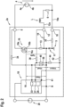
- Figure 2 shows a circuit diagram of an SSPC 2a, which allows controlling the supply of electric power to a load 6 in an aircraft 1.
- the SSPC 2a comprises an input node ("feed node") 8, which is electrically connected to a first output node 4a of the aircraft electric power supply ("primary power supply”) 4, and a return node 10, which is electrically connected to a second output node 4b of the aircraft electric power supply 4.
- the return node 10 is also electrically connected to the electric ground 5 of the aircraft 1.
- a line impedance is indicated by 32.
- the feed node 8 may be connected to a first electric supply voltage (e.g. positive supply voltage) and the return node 10 may be electrically connected to a second electric supply voltage (e.g. negative supply voltage).
- the SSPC 2a further comprises an output node ("load node") 12.
- the electric load 6 is connected between the load node 12 and the return node 10/ second output node 4b of the aircraft electric power supply 4 for being selectively supplied with electric power from the aircraft electric power supply 4 via the SSPC 2a.
- an inductivity L represents an inductivity of the electric load 6 and/or an inductivity of the power supply lines 10a, 12a, which connect the electric load 6 with the SSPC 2a.
- a free-wheeling diode 11 is connected between the return node 10 and the load node 12 of the SSPC 2a.
- a thermal fuse 14 is connected in between the feed node 8 and the load node 12.
- the SSPC 2a comprises an electric switching device 16, in particular a solid state switching device 16, connected in between the feed node 8 and the load node 12.
- the electric switching device 16 comprises a first terminal 16a, a second terminal 16b, and a control terminal 16c.
- the first terminal 16a of the electric switching device 16 is electrically connected with the feed node 8 of the SSPC 2a.
- the second terminal 16b of the electric switching device 16 is electrically connected with the load node 12 of the SSPC 2a (e.g. via a shunt resistor 13 for measuring load current and thermal fuse 14, as shown in the embodiment of Figure 2 ).
- the electric switching device 16 may be a solid state switching device, in particular a transistor such as a bipolar transistor, an insulated-gate bipolar transistor (IGBT), or a field-effect transistor (FET), in particular a metal-oxide-semiconductor field-effect transistor (MOSFET).
- a transistor such as a bipolar transistor, an insulated-gate bipolar transistor (IGBT), or a field-effect transistor (FET), in particular a metal-oxide-semiconductor field-effect transistor (MOSFET).
- the thermal fuse 14 is connected between the second terminal 16b of the electric switching device 16 and the load node 12 of the SSPC 2.
- a shunt resistor 13 is connected between the second terminal 16b of the electric switching device 16 and the load node 12.
- the shunt resistor 13 is configured for measuring a load current flowing through the load 6 when the electric switching device 16 is switched on.
- the resistance of the shunt resistor 13 is relatively low, in the range of 1 m ⁇ to 100 m ⁇ , in particular in the range of 1 m ⁇ to 10 m ⁇ , thus the voltage drop V shunt over the shunt resistor 13 is very small and generally negligible.
- V gate an appropriate control voltage
- the SSPC 2a also comprises an electric switching device controller 18 with a control output node 19.
- the control output node 19 is electrically connected to the control node 16c of the electric switching device 16 for selectively supplying appropriate control voltages to the electric switching device 16.
- the electric switching device 16 may be switched between its low-resistive on-state and its high-resistive off-state for selectively activating and deactivating the electric load 6, which is electrically connected to the SSPC 2a.
- the electric switching device controller 18 is supplied with electric power from a switching device controller power supply 20.
- the switching device controller power supply 20 is configured to be independent of the primary power supply 4.
- the switching device controller power supply 20 may in particular be galvanically separated from the primary power supply 4.
- the switching device controller power supply 20 may be configured for providing a DC voltage, which may be in the range from 5 V to 30 V, in particular in the range of 10 V to 28 V, to the electric switching device controller 18.
- both the load voltage V load and the feed voltage V feed are detected with respect to a common reference voltage B by respective voltage dividers 34/36 (for the load voltage V load , see 33) and 38/40 (for the feed voltage V feed , see 37).
- An additional voltage divider 42/44 is configured to detect a return voltage V return of the return node 10 (see 41) with respect to the reference voltage B.
- the off-resistance of the electric switching device 16 is very large, and therefore the voltage drop between the first and second terminals 16, 16b of the electric switching device 16 is approximately equal to the feed voltage V feed and the voltage V load at the electric load 6 is approximately equal to the voltage at the return node 10/negative pole 4b of the primary power supply 4.
- the voltage drop V switch between the first and second terminals 16, 16b of the electric switching device 16 is determined by the on-resistance of the electric swicthhing device und thus is close to zero (compared to the feed voltage V feed ).
- the actual switching state of the electric switching device 16 may be determined indirectly by measuring the voltages V load and V feed with respect to reference voltage B and calculating a difference V feed - V load .
- a feed voltage V feed needs to be supplied to the feed node 8 and return node 10 by the primary power supply 4 to the SSPC 2a.
- the described method of determining the actual switching state of the electric switching device 16 cannot be applied when the feed voltage V feed is not available, for example since the SSPC 2a is not connected to the primary power supply 4, or the primary power supply 4 is not operating.
- measuring V load and V feed as described above requires a relatively complicated setup of voltage measurements and voltage dividers, in order to determine the switching condition of the electric switching device 16 indirectly as the difference between V feed and V load .
- the validity of the test result may be deteriorated by back-feeding voltage from the electric load 6. Due to the large variety of possible electric loads 6 having different electric properties, which may be connected to the SSPC 2a, it is rather difficult to set up a reliable detection algorithm, which allows for reliably differentiating between a correct function and a malfunction of the electric switching device 16.
- Figure 3 shows a circuit diagram of an SSPC 2b according to an exemplary embodiment of the invention.
- the SSPC 2b of Figure 3 largely has the same configuration as the SSPC 2a of Figure 2 . Therefore, only components different from the SSPC 2a of Figure 2 are depicted in Figure 3 and described in further detail hereinafter. A number of components have been omitted in Figure 3 for sake of clarity. Reference is made to Figure 2 and its description with respect to such components that have been omitted in Figure 3 .
- the primary power supply 4 and the electric load 6 are not depicted in Figure 3 .
- the primary power supply 4 and the electric load 6 may be connected to the input node 8, to the output node 12, and to the return node 10, as it is depicted in Figure 2 .
- the SSPC 2b depicted in Figure 3 comprises a solid switching device test circuit 22, which is electrically connected to the first terminal 16a and to the second terminal 16b of the electric switching device 16 for monitoring the switching state of the electric switching device 16.
- the solid switching device test circuit 22 is configured for monitoring the switching state of the electric switching device 16 directly.
- the solid switching device test circuit 22 is in particular configured for monitoring the switching state of the electric switching device 16 independently of the feed voltage V feed , which is supplied by the primary power supply (which is not shown in Figure 3 ).
- the solid switching device test circuit 22 comprises a secondary electric power supply 24, which is independent of the primary power supply 4.
- the secondary electric power supply 24 is configured for providing a test voltage V iso , in particular a DC voltage V iso in the range of 5 V to 30 V, in particular in the range of 10 V to 28 V.
- the secondary electric power supply 24 may be galvanically isolated from its power supply, particularly from the primary electric power supply 4. This is schematically indicated by a dashed line in Figure 3 .
- the test voltage V iso supplied by the secondary electric power supply 24 is applied to the first and second terminals 16a, 16b of the electric switching device 16.
- the ground voltage or reference voltage GND iso of the secondary electric power supply 24 is in particular electrically connected to the load node 12 of the SSPC 2 (and thus basically corresponds to the voltage at the second terminal 16b of the electric switching device 16, as the resistance of the shunt resistor 13 is very small).
- the test voltage V iso supplied by the secondary electric power supply 24 is referenced to the load node 12 of the SSPC 2 or to the second terminal 16b of the electric switching device 16.
- the solid switching device test circuit 22 further comprises a voltage sensor 26, which is configured for detecting the voltage drop ⁇ V over a test resistor R, which is connected between the of the load node 12 of the SSPC 2b and the ground voltage or reference voltage GND iso of the secondary electric power supply 24.
- the test resistor R may have a resistivity in the range of between100 ⁇ and 680 kO .
- the resistivity of the test resistor R may in particular be set high in comparison to the resistivity of the load 6 in order to avoid adding a considerable additional load to the electric switching device 16.
- the voltage sensor 26 may be integrated with the secondary electric power supply 24, or it may be provided separately from the secondary electric power supply 24.
- the voltage drop V switch over the electric switching device 16 (including switching device 16 and shunt resistor 13) is lower than 1 V, depending on the type of the electric switching device 16.
- the voltage drop V switch over the electric switching device 16 may in particular be in the range of 0.3 V to 0.7 V.
- the voltage drop ⁇ V V iso - V switch over the test resistor R, which is detected by the voltage sensor 26, is close or equal to the test voltage V iso that is applied by the secondary electric power supply 24 to the input node 16a of the electric switching device 16.
- the voltage drop V switch over the electric switching device 16 is close or equal to the test voltage V iso .
- the solid switching device test circuit 22 may be configured to provide a test signal VOA that is based on the voltage drop ⁇ V over the test resistor R and that is indicative of the switching state of the electric switching device 16.
- the solid switching device test circuit 22 may in particular comprise a comparator 28, which is configured for comparing the detected voltage drop ⁇ V over the test resistor R with a predefined reference voltage V ref , and for providing a binary test signal VOA indicating whether the detected voltage drop ⁇ V is higher of lower than the predefined reference voltage V ref .
- the comparator 28 may comprise a first input 27 for receiving a voltage signal delivered by the voltage sensor 26, and a second input 29 for receiving the predefined reference voltage V ref .
- the predefined reference voltage V ref may, for example be provided by the secondary power supply 24, and thus may be equal to, or at least derived from, the voltage V lso of the secondary electric power supply 24.
- the reference voltage V ref may be generated within the comparator 28 by an appropriate reference voltage generation circuit.
- the switching state of the electric switching device 16 may be detected directly and independently of the feed voltage V feed supplied by the primary electric power supply 4. In consequence, there is no risk that the detection of the switching state of the electric switching device 16 is deteriorated by any loads currents flowing through the electric load 6.
- the secondary electric power supply 22 is independent of the primary electric power supply, it is not required to use a complicated resistor network for providing suitable voltage dividers for measuring the voltages V feed , V load and V return as shown in Figure 2 .
- the switching state of the electric switching device 16 may be monitored conveniently and very reliably, and the operational safety of the SSPC 2b may be enhanced.
- the circuit branch including the return node 10, resistor 32 and free-wheeling diode 11 is optional and not required for using the solid switching device test circuit 22 as described above.
- the feed voltage may be supplied via the feed node 8 and supplied to the load (see reference sign 6 in Figure 2 ) via the load node 12, depending on the switching state of the electric switching device 16.
- the load 6 may be connected to ground or to the opposite pole of the feed voltage source.
- Inductive electric voltages which may be induced by the inductivity L when the supply of electric power to the electric load 6 is switched off, may be dissipated through the body of the electric switching device 16 in such embodiments. This also applies for the embodiment shown in Figure 4 .
- Figure 4 shows a circuit diagram of an SSPC 2c according to another exemplary embodiment of the invention.
- the primary power supply 4 and the electric load 6 are not depicted in Figure 4 .
- the primary power supply 4 and the electric load 6 may be connected to the feed node 8, to the load node 12, and to the return node 10, as it is depicted in Figure 2 .
- FIG 4 shows an electric switching device controller 18 which is configured for providing a control signal (usually a control voltage) to the control terminal 16c of the electric switching device 16.
- the electric switching device 16 is configured to switch between its on-state and its off-state depending on the control signal applied to the control terminal 16c.
- the switching device controller power supply 20 may be connected to the feed node 8 of the SSPC 2c via a resistor and a diode, and may be connected to the load node 12 of the SSPC 2c, as shown in the embodiment of Figure 4 .
- the switching device controller power supply 20, which is simultaneously employed as the secondary electric power supply 24, is independent of the primary power supply 4 of the aircraft 1, which provides the feed voltage V feed to the input node (fee node) 8.
- the switching device controller power supply 20 / secondary electric power supply 24 may in particular be galvanically isolated from the primary electric power supply 4, and the test voltage V iso , which is output by the switching device controller power supply 20 / secondary electric power supply 24, may be referenced to the output node 12 of the SSPC 2c.
- the voltage drop V switch over the electric switching device 16 may be detected by a voltage sensor 26, which may be implemented as part of the electric switching device controller 18, as it is depicted in Figure 4 .
- a separate voltage sensor 26 may be provided separately from the electric switching device controller 18.
- the voltage sensor 26 may include or may be connected to a comparator 28 for providing a binary test signal VOA indicating whether the detected voltage drop V switch is above or below a predefined reference voltage V ref , as it has been described before with reference to Figure 3 .
- the embodiment depicted in Figure 4 allows for reliably and conveniently detecting the actual switching state of the electric switching device 16 independently of the feed voltage V feed , which is supplied by the primary power supply 4. It further allows detecting the actual switching state of the electric switching device 16 independently of any load currents flowing through electric loads 6 that are connected to the SSPC 2c.
- controller power supply 20 as the secondary electric power supply 24 for supplying the test voltage V iso to the electric switching device 16, as it is depicted in Figure 4 , avoids the need of providing an additional power supply in addition to the controller power supply 20.
- the number of isolated power supplies 20, 24, which are independent of the primary power supply 4 of the aircraft may be reduced from two to one.
- Figure 5 shows a circuit diagram of an SSPC 2d according to yet another exemplary embodiment of the invention.
- the SSPC 2d depicted in Figure 5 is based on the SSPC 2d depicted in Figure 4 , but it comprises two electric switching devices 16, 17, in order to allow switching an AC feed voltage V feed , which is to be supplied via feed node 8 of the SSPC 2d to a load connected to the load node 12.
- the voltage sensor 26 provided within the electric switching device controller 18 may detect the two voltage drops V switch1 , V switch2 over the first and second electric switching devices 16, 17 respectively, in order to determine the current switching state of the respective electric switching device 16, 17.
- the first voltage drop V switch1 includes the voltage drop over the shunt resistor 13. However, since the resistivity of the shunt resistor is small, the additional voltage drop is small, too. The additional voltage drop may be taken into account, when first voltage drop V switch1 is evaluated, i.e. by comparing the first voltage drop V switch1 with a predefined threshold.
- V switch1 , V switch2 over the first and second electric switching devices 16, 17 will pulsate, when the electric switching devices 16, 17 are switched off.
- the voltage drop V switch1 , V switch2 over each of the first and second electric switching devices 16, 17 will be constantly low, when the respective electric switching device 16, 17 is switched on.
- the body diodes of the first and second electric switching devices 16, 17 may become conductive and cause an erroneous detection of a false on state.
- V switch1 it is important to measure V switch1 only when a positive voltage is applied to node 8.
- the second electric device 17 may be in an undetermined state.
- V switch2 shall be measured only when a positive voltage is applied to node 12. In this case, the second electric switching device 16 may be in an undetermined state.
Landscapes
- Engineering & Computer Science (AREA)
- Power Engineering (AREA)
- Direct Current Feeding And Distribution (AREA)
Abstract
Description
- The invention is related to aircraft solid state power controller ("SSPC") for controlling the supply of electric power from an aircraft electric power supply to at least one electric load within an aircraft. The invention is further related to a method of operating such an aircraft solid state power controller.
- Modern aircraft usually comprise at least one aircraft solid state power controller ("SSPC") for controlling the supply of electric power from an aircraft electric power supply to at least one electric load. The at least one SSPC in particular includes at least one electric switching device, in particular at least one solid state switching device, which is configured for selectively switching the electric power supplied to the at least one electric load. For securing a secure and reliable operation of the at least one SSPC, the functionality of the at least one electric switching device is to be regularly checked.
- It therefore would be beneficial to provide an improved SSPC including at least one electric switching device, wherein the SSPC allows for an easy, fast and reliable checking of the functionality of the at least one electric switching device.
- According to an exemplary embodiment of the invention, an aircraft solid state power controller ("SSPC") for controlling the supply of electric power from an aircraft electric power supply to at least one electric load within an aircraft comprises a feed node, which is to be electrically connected to a primary electric power supply of the aircraft; a load node, which is to be electrically connected to the at least one electric load; and at least one electric switching device, in particular at least one solid state switching device, which is arranged between the feed node and the load node for controlling the supply of electric power from the feed node to the load node.
- The at least one electric switching device is in particular switchable between an on-state, in which the at least one electric switching device provides a low-resistive electric connection between the feed node and the load node; and a high-resistive off-state, in which the at least one electric switching device electrically isolates the at least one load node from the feed node.
- The SSPC further comprises a secondary electric power supply, which is independent from the primary electric power supply. The secondary electric power supply is configured for applying a test voltage between the feed node and the load node of the SSPC in order to allow for determining the switching state of the at least one electric switching device by detecting a voltage drop between the feed node and the load node. As the secondary power supply is independent from the primary power supply, the switching state of the at least one electric switching device can be detected independent of whether the primary electric power supply is connected to the feed node.
- Exemplary embodiments of the invention also include an aircraft, such as an airplane or a helicopter, comprising at least one electric power supply and at least one SSPC according to an exemplary embodiment of the invention.
- Exemplary embodiments of the invention further include a method of operating an SSPC, wherein the SSPC comprises a feed node, which is to be electrically connected to a primary electric power supply; aload node, which is to be electrically connected to at least one electric load; and at least one electric switching device, in particular at least one solid state switching device, which is arranged between the feed node and the load node for switching the supply of electric power from the feed node to the load node; wherein the method comprises: selectively switching the at least one electric switching device between an on-state, in which the at least one electric switching device provides a low-resistive electric connection between the feed node and the load node so that the primary power supply is electrically connected with the electric load; and a high-resistive off-state, in which the at least one electric switching device electrically isolates the load node from the feed node; applying a test voltage between the feed node and the load node of the SSPC; wherein the test voltage is provided by a secondary electric power supply, which is independent from the primary electric power supply; and determining the switching state of the at least one electric switching device by detecting a voltage drop between the feed node and the load node of the SSPC.
- With an SSPC according to an exemplary embodiment of the invention, the switching state of the at least one electric switching device may be detected independently of a feed voltage supplied by the primary electric power supply. In addition, in an SSPC according to an exemplary embodiment of the invention, the detection of the switching state of the at least one electric switching device is not deteriorated by the electric load. As a result, the switching state of the at least one electric switching device may be monitored very reliably, and the operational safety of the SSPC may be enhanced. A signal indicative of the correct operation, or the switching state, of the electric switching device may be provided independent of other operations of the SSPC, particularly independent of the primary electric power supply.
- The at least one electric switching device may be a solid state switching device, in particular a transistor such as a bipolar transistor, an insulated-gate bipolar transistor (IGBT), or a field-effect transistor (FET), in particular a metal-oxide-semiconductor field-effect transistor (MOSFET). Such electric switching devices provide very reliable and efficient electric switching devices.
- Particular embodiments may further include one, or a plurality, of the following optional features. These optional features may be applied separately, or in combination with each other, unless specified otherwise.
- In an embodiment, the secondary electric power supply is galvanically isolated from the primary electric power supply in order to provide an electric separation between the primary electric power supply and the secondary electric power supply. Such an electric separation allows preventing any undesirable interactions between the primary electric power supply and the secondary electric power supply.
- In an embodiment, the SSPC comprises further electric power supplies, which are provided for supplying electric power to further electric components of the SSPC, and the secondary electric power supply is galvanically isolated from, these additional power supplies as well.
- In an embodiment, the SSPC comprises an integrated circuit including an isolated DC power supply, which is employed as the secondary power supply. The integrated circuit may, for example, include a controller for controlling the operation of the SSPC. Providing the secondary power supply as part of an integrated circuit of the SSPC is a very efficient way of providing the secondary power supply.
- In an embodiment, the secondary power supply may be provided as a separate secondary power supply. This allows for a clear separation between the SSPC and/or electric components of the SSPC and the secondary power supply.
- In an embodiment, the secondary power supply may be provided as a shared secondary power supply for applying the test voltage between the feed node and the load node and for providing also other voltages, for example a voltage for operating a controller of the SSPC and/or a control voltage, which is to be applied to a control terminal of the at least one electric switching device. Such an embodiment allows using the secondary power supply very efficiently.
- In an embodiment, the integrated circuit including the power supply is a DC/DC power chip, in particular an ADUM 5241 chip or an ADUM 5242 chip.
- In an embodiment, the at least one electric switching device comprises a control terminal for receiving a control voltage for controlling/switching the at least one electric switching device at least between a low-resistive on-state and a high-resistive off-state. In such an embodiment, the SSPC may further comprise an electric switching device controller, which is configured applying the control voltage to the control terminal of the at least one electric switching device for selectively switching the at least one electric switching device at least between the on-state and the off-state.
- In an embodiment, the secondary power supply is configured for providing electric power for supplying the control voltage to the control terminal of the at least one electric switching device. This allows for a very efficient use of the secondary power supply.
- In an embodiment, the electric switching device comprises a first terminal connected to the feed node and a second terminal connected to the load node, and the secondary power supply is referenced to the second terminal of the at least one electric switching device, or to a reference point between the second terminal and the load node of the solid state power controller, in order to apply a defined electric test voltage between the feed node and the load node of the at least one electric switching device.
- In an embodiment, the SSPC further comprises a test voltage sensor, which is configured for detecting a voltage drop which allows determining the switching state of the at least one electric switching device. The voltage sensor may in particular be configured for detecting the above mentioned voltage drop between the feed node and the load node of the solid state switching element when applying the test voltage Viso. In an embodiment, such voltage drop between the feed node and the load node of the solid state switching element element when applying the test voltage Viso may be detected by connecting a test voltage measurement resistor in series with the solid state switching element and parallel to the load node and detecting a voltage drop across the test voltage resistor element when applying the test voltage Viso. .
- In an embodiment, the test voltage sensor is configured to deliver a signal indicating whether the at least one electric switching device is in its on-state or in its off-state. The test voltage sensor may in particular be configured for delivering a binary signal.
- In an embodiment, the SSPC comprises a test voltage sensor, which is configured for detecting a voltage drop that allows determining the switching state of the at least one electric switching device, and a comparator, which is configured for comparing the voltage signal detected by the test voltage sensor with a reference voltage, and for providing a binary signal indicating the switching state of the at least one electric switching device based on the comparison. The status of the binary signal may depend on whether the voltage drop, as it is detected by the test voltage sensor, exceeds the predefined reference voltage or not.
- In an embodiment, the comparator comprises a first input for receiving a voltage signal delivered by the test voltage sensor and indicating the voltage drop, and a second input for receiving the reference voltage. This allows the comparator to compare the voltage drop measured by the test voltage sensor with a predefined reference voltage, which is supplied to the comparator.
- In the following, exemplary embodiments of the invention are described with reference to the enclosed figures.
-
Figure 1 shows an aircraft comprising an aircraft electric power supply system including an SSPC according to an exemplary embodiment of the invention. -
Figure 2 shows a circuit diagram of an SSPC, which allows controlling the supply of electric power to a load in an aircraft. -
Figure 3 shows a circuit diagram of an SSPC according to an exemplary embodiment of the invention. -
Figure 4 shows a circuit diagram of an SSPC according to another exemplary embodiment of the invention. -
Figure 5 shows a circuit diagram of an SSPC according to an exemplary embodiment of the invention, which is capable to switch AC voltages. -
Figure 1 shows anaircraft 1, in particular an airplane, which is equipped with an aircraft electricpower supply system 3. The aircraft electricpower supply system 3 includes an aircraftelectric power supply 4, anelectric load 6, and an aircraft solid state power controller ("SSPC") 2 according to an exemplary embodiment of the invention, which is configured for controlling the supply of electric power from the aircraftelectric power supply 4 to theelectric load 6. - Although the aircraft electric
power supply system 3, as depicted inFigure 1 , includes only a single aircraftelectric power supply 4, a singleelectric load 6, and asingle SSPC 2, respectively, it is to be understood that this is a simplified representations for reasons of clarifying the teachings of the present disclosure. Embodiments of an aircraft electricpower supply system 3 may comprise more the one of each of said components, respectively. Particularly, embodiments of an aircraft electricpower supply system 3 may comprise a plurality of SSPC's 2 connected todifferent loads 6, respectively. - An aircraft electric
power supply system 3 may in particular include a plurality ofSSPCs 2, wherein each SSPC 2 includes numerous SSPC channels of the types, which are depicted inFigure 2 to 4 and described in the following. -
Figure 2 shows a circuit diagram of anSSPC 2a, which allows controlling the supply of electric power to aload 6 in anaircraft 1. - The SSPC 2a comprises an input node ("feed node") 8, which is electrically connected to a
first output node 4a of the aircraft electric power supply ("primary power supply") 4, and areturn node 10, which is electrically connected to asecond output node 4b of the aircraftelectric power supply 4. In the embodiment shown, thereturn node 10 is also electrically connected to theelectric ground 5 of theaircraft 1. A line impedance is indicated by 32. In alternative embodiments, thefeed node 8 may be connected to a first electric supply voltage (e.g. positive supply voltage) and thereturn node 10 may be electrically connected to a second electric supply voltage (e.g. negative supply voltage). - The SSPC 2a further comprises an output node ("load node") 12. The
electric load 6 is connected between theload node 12 and thereturn node 10/second output node 4b of the aircraftelectric power supply 4 for being selectively supplied with electric power from the aircraftelectric power supply 4 via the SSPC 2a. - In
Figure 2 , an inductivity L represents an inductivity of theelectric load 6 and/or an inductivity of thepower supply lines electric load 6 with theSSPC 2a. - For dissipating inductive electric voltages, which may be induced by the inductivity L when the supply of electric power to the
electric load 6 is switched off, a free-wheelingdiode 11 is connected between thereturn node 10 and theload node 12 of theSSPC 2a. Athermal fuse 14 is connected in between thefeed node 8 and theload node 12. - The
SSPC 2a comprises anelectric switching device 16, in particular a solidstate switching device 16, connected in between thefeed node 8 and theload node 12. Theelectric switching device 16 comprises afirst terminal 16a, asecond terminal 16b, and acontrol terminal 16c. Thefirst terminal 16a of theelectric switching device 16 is electrically connected with thefeed node 8 of theSSPC 2a. The second terminal 16b of theelectric switching device 16 is electrically connected with theload node 12 of theSSPC 2a (e.g. via ashunt resistor 13 for measuring load current andthermal fuse 14, as shown in the embodiment ofFigure 2 ). - The
electric switching device 16 may be a solid state switching device, in particular a transistor such as a bipolar transistor, an insulated-gate bipolar transistor (IGBT), or a field-effect transistor (FET), in particular a metal-oxide-semiconductor field-effect transistor (MOSFET). - The
thermal fuse 14 is connected between the second terminal 16b of theelectric switching device 16 and theload node 12 of theSSPC 2. Ashunt resistor 13 is connected between the second terminal 16b of theelectric switching device 16 and theload node 12. Theshunt resistor 13 is configured for measuring a load current flowing through theload 6 when theelectric switching device 16 is switched on. The resistance of theshunt resistor 13 is relatively low, in the range of 1 mΩ to 100 mΩ, in particular in the range of 1 mΩ to 10 mΩ, thus the voltage drop Vshunt over theshunt resistor 13 is very small and generally negligible. - By applying an appropriate control voltage ("Vgate") to the
control terminal 16c of theelectric switching device 16, theelectric switching device 16 is switchable between an on-state, in which the electric resistivity between first terminal 16a and thesecond terminal 16b is low, and an off-state, in which the electric resistivity between first terminal 16a and thesecond terminal 16b is high. - The
SSPC 2a also comprises an electricswitching device controller 18 with acontrol output node 19. Thecontrol output node 19 is electrically connected to thecontrol node 16c of theelectric switching device 16 for selectively supplying appropriate control voltages to theelectric switching device 16. By supplying appropriate control voltages to theelectric switching device 16, theelectric switching device 16 may be switched between its low-resistive on-state and its high-resistive off-state for selectively activating and deactivating theelectric load 6, which is electrically connected to theSSPC 2a. - The electric
switching device controller 18 is supplied with electric power from a switching devicecontroller power supply 20. The switching devicecontroller power supply 20 is configured to be independent of theprimary power supply 4. The switching devicecontroller power supply 20 may in particular be galvanically separated from theprimary power supply 4. - The switching device
controller power supply 20 may be configured for providing a DC voltage, which may be in the range from 5 V to 30 V, in particular in the range of 10 V to 28 V, to the electricswitching device controller 18. - For monitoring the correct operation of the
electric switching device 16, the input voltage ("feed voltage Vfeed") between thefeed node 8 and thereturn node 10 of theSSPC 2a as well as the output voltage ("load voltage Vload") between theload node 12 and thereturn node 10 of theSSPC 2a may be detected by avoltage sensor 26 within the electricswitching device controller 18, and the voltage drop Vswitch over theelectric switching device 16 may be determined indirectly as the difference between the feed voltage Vfeed and load voltage Vload: Vswitch = Vfeed - Vload. - In a conventional configuration as shown in
Figure 2 , both the load voltage Vload and the feed voltage Vfeed are detected with respect to a common reference voltage B byrespective voltage dividers 34/36 (for the load voltage Vload, see 33) and 38/40 (for the feed voltage Vfeed, see 37). Anadditional voltage divider 42/44 is configured to detect a return voltage Vreturn of the return node 10 (see 41) with respect to the reference voltage B. By subtracting the signal provided by the voltage divider 38/40 from the signal provided from thevoltage divider 34/36 it is possible to calculate the voltage drop Vswitch over the electric switching device 16 (including switchingdevice 16 and shunt resistor 13). This configuration requires a microcontroller and is dependent on supply of the feed voltage to between thefeed node 8 and return node of theSSPC 2a. - When the
electric switching device 16 is switched off, the off-resistance of theelectric switching device 16 is very large, and therefore the voltage drop between the first andsecond terminals electric switching device 16 is approximately equal to the feed voltage Vfeed and the voltage Vload at theelectric load 6 is approximately equal to the voltage at thereturn node 10/negative pole 4b of theprimary power supply 4. When theelectric switching device 16 is switched on, the voltage drop Vswitch between the first andsecond terminals electric switching device 16 is determined by the on-resistance of the electric swicthhing device und thus is close to zero (compared to the feed voltage Vfeed). Hence, Vload ≈ Vfeed in the on-switching state of theelectric switching device 16. - Thus, the actual switching state of the
electric switching device 16 may be determined indirectly by measuring the voltages Vload and Vfeed with respect to reference voltage B and calculating a difference Vfeed - Vload. - In order to be able to monitor the correct operation of the
electric switching device 16 as it has been described before, a feed voltage Vfeed needs to be supplied to thefeed node 8 and returnnode 10 by theprimary power supply 4 to theSSPC 2a. In consequence, the described method of determining the actual switching state of theelectric switching device 16 cannot be applied when the feed voltage Vfeed is not available, for example since theSSPC 2a is not connected to theprimary power supply 4, or theprimary power supply 4 is not operating. Moreover, measuring Vload and Vfeed as described above requires a relatively complicated setup of voltage measurements and voltage dividers, in order to determine the switching condition of theelectric switching device 16 indirectly as the difference between Vfeed and Vload. - Further, the validity of the test result, which may be achieved by the described method, may be deteriorated by back-feeding voltage from the
electric load 6. Due to the large variety of possibleelectric loads 6 having different electric properties, which may be connected to theSSPC 2a, it is rather difficult to set up a reliable detection algorithm, which allows for reliably differentiating between a correct function and a malfunction of theelectric switching device 16. - It is therefore desirable to provide an
improved SSPC 2, which overcomes the above mentioned problems. -
Figure 3 shows a circuit diagram of anSSPC 2b according to an exemplary embodiment of the invention. TheSSPC 2b ofFigure 3 largely has the same configuration as theSSPC 2a ofFigure 2 . Therefore, only components different from theSSPC 2a ofFigure 2 are depicted inFigure 3 and described in further detail hereinafter. A number of components have been omitted inFigure 3 for sake of clarity. Reference is made toFigure 2 and its description with respect to such components that have been omitted inFigure 3 . - The components of the
SSPC 2b that correspond to respective components of theSSPC 2a depicted inFigure 2 are denoted with the same references and are not discussed in detail again. Reference is made to the corresponding description ofFigure 2 . - For enhancing the clarity of the illustration, the
primary power supply 4 and theelectric load 6 are not depicted inFigure 3 . Theprimary power supply 4 and theelectric load 6 may be connected to theinput node 8, to theoutput node 12, and to thereturn node 10, as it is depicted inFigure 2 . - The
SSPC 2b depicted inFigure 3 comprises a solid switchingdevice test circuit 22, which is electrically connected to thefirst terminal 16a and to the second terminal 16b of theelectric switching device 16 for monitoring the switching state of theelectric switching device 16. - The solid switching
device test circuit 22 is configured for monitoring the switching state of theelectric switching device 16 directly. The solid switchingdevice test circuit 22 is in particular configured for monitoring the switching state of theelectric switching device 16 independently of the feed voltage Vfeed, which is supplied by the primary power supply (which is not shown inFigure 3 ). - The solid switching
device test circuit 22 comprises a secondaryelectric power supply 24, which is independent of theprimary power supply 4. The secondaryelectric power supply 24 is configured for providing a test voltage Viso, in particular a DC voltage Viso in the range of 5 V to 30 V, in particular in the range of 10 V to 28 V. The secondaryelectric power supply 24 may be galvanically isolated from its power supply, particularly from the primaryelectric power supply 4. This is schematically indicated by a dashed line inFigure 3 . - The test voltage Viso supplied by the secondary
electric power supply 24 is applied to the first andsecond terminals electric switching device 16. The ground voltage or reference voltage GNDiso of the secondaryelectric power supply 24 is in particular electrically connected to theload node 12 of the SSPC 2 (and thus basically corresponds to the voltage at the second terminal 16b of theelectric switching device 16, as the resistance of theshunt resistor 13 is very small). In consequence, the test voltage Viso supplied by the secondaryelectric power supply 24 is referenced to theload node 12 of theSSPC 2 or to the second terminal 16b of theelectric switching device 16. - The solid switching
device test circuit 22 further comprises avoltage sensor 26, which is configured for detecting the voltage drop ΔV over a test resistor R, which is connected between the of theload node 12 of theSSPC 2b and the ground voltage or reference voltage GNDiso of the secondaryelectric power supply 24. - The test resistor R may have a resistivity in the range of between100 Ω and 680 kO . The resistivity of the test resistor R may in particular be set high in comparison to the resistivity of the
load 6 in order to avoid adding a considerable additional load to theelectric switching device 16. - The
voltage sensor 26 may be integrated with the secondaryelectric power supply 24, or it may be provided separately from the secondaryelectric power supply 24. - When the
electric switching device 16 is switched on, i.e. when theelectric switching device 16 is in a low resistive state (referred to as the on-resistance of the electric switching device 16) compared to the resistance of the test resistor R, the voltage drop Vswitchover the electric switching device 16 (including switchingdevice 16 and shunt resistor 13) is lower than 1 V, depending on the type of theelectric switching device 16. The voltage drop Vswitch over theelectric switching device 16 may in particular be in the range of 0.3 V to 0.7 V. In consequence, the voltage drop ΔV = Viso - Vswitchover the test resistor R, which is detected by thevoltage sensor 26, is close or equal to the test voltage Viso that is applied by the secondaryelectric power supply 24 to theinput node 16a of theelectric switching device 16. - When the
electric switching device 16 is switched off, i.e. when theelectric switching device 16 is in a high resistive state (referred to as the off-resistance of the electric switching device 16) compared to the resistance of the test resistor R, the voltage drop Vswitch over theelectric switching device 16 is close or equal to the test voltage Viso. In consequence the voltage drop ΔV = Viso - Vswitch over the test resistor R is close or equal to zero. - The solid switching
device test circuit 22 may be configured to provide a test signal VOA that is based on the voltage drop ΔV over the test resistor R and that is indicative of the switching state of theelectric switching device 16. - The solid switching
device test circuit 22 may in particular comprise acomparator 28, which is configured for comparing the detected voltage drop ΔV over the test resistor R with a predefined reference voltage Vref, and for providing a binary test signal VOA indicating whether the detected voltage drop ΔV is higher of lower than the predefined reference voltage Vref. - The
comparator 28 may comprise afirst input 27 for receiving a voltage signal delivered by thevoltage sensor 26, and asecond input 29 for receiving the predefined reference voltage Vref. The predefined reference voltage Vref may, for example be provided by thesecondary power supply 24, and thus may be equal to, or at least derived from, the voltage Vlso of the secondaryelectric power supply 24. Alternatively, the reference voltage Vref may be generated within thecomparator 28 by an appropriate reference voltage generation circuit. - With an
SSPC 2b comprising a solid switchingdevice test circuit 22, as it is depicted inFigure 3 , the switching state of theelectric switching device 16 may be detected directly and independently of the feed voltage Vfeed supplied by the primaryelectric power supply 4. In consequence, there is no risk that the detection of the switching state of theelectric switching device 16 is deteriorated by any loads currents flowing through theelectric load 6. As the secondaryelectric power supply 22 is independent of the primary electric power supply, it is not required to use a complicated resistor network for providing suitable voltage dividers for measuring the voltages Vfeed, Vload and Vreturn as shown inFigure 2 . - As a result, the switching state of the
electric switching device 16 may be monitored conveniently and very reliably, and the operational safety of theSSPC 2b may be enhanced. - The circuit branch including the
return node 10,resistor 32 and free-wheelingdiode 11 is optional and not required for using the solid switchingdevice test circuit 22 as described above. In an embodiment not using a separate free-wheelingdiode 11, the feed voltage may be supplied via thefeed node 8 and supplied to the load (seereference sign 6 inFigure 2 ) via theload node 12, depending on the switching state of theelectric switching device 16. Theload 6 may be connected to ground or to the opposite pole of the feed voltage source. Inductive electric voltages, which may be induced by the inductivity L when the supply of electric power to theelectric load 6 is switched off, may be dissipated through the body of theelectric switching device 16 in such embodiments. This also applies for the embodiment shown inFigure 4 . -
Figure 4 shows a circuit diagram of an SSPC 2c according to another exemplary embodiment of the invention. - In
Figure 4 , the components of the SSPC 2c that correspond to the respective components of theSSPCs Figures 2 and3 are denoted with the same references and are not discussed in detail again. Reference is made to the description ofFigures 2 and3 with respect to such components. - For enhancing the clarity of the illustration, the
primary power supply 4 and theelectric load 6 are not depicted inFigure 4 . Theprimary power supply 4 and theelectric load 6 may be connected to thefeed node 8, to theload node 12, and to thereturn node 10, as it is depicted inFigure 2 . -
Figure 4 shows an electricswitching device controller 18 which is configured for providing a control signal (usually a control voltage) to thecontrol terminal 16c of theelectric switching device 16. Theelectric switching device 16 is configured to switch between its on-state and its off-state depending on the control signal applied to thecontrol terminal 16c. The control signal is referenced to one the first orsecond terminals Figure 4 to thesecond terminal 16b = source in case of a MOSFET 16) of theelectric switching device 16 and is provided by thecontrol signal terminal 19 of the electricswitching device controller 18. - In the embodiment depicted in
Figure 4 , the switching devicecontroller power supply 20, which is employed for supplying electric power to the electricswitching device controller 18 is simultaneously employed as the secondaryelectric power supply 24 for supplying the test voltage Viso = Vcontroller, which is applied to thefeed node 8 andlode node 12 of the SSPC 2c. For example, the switching devicecontroller power supply 20 may be connected to thefeed node 8 of the SSPC 2c via a resistor and a diode, and may be connected to theload node 12 of the SSPC 2c, as shown in the embodiment ofFigure 4 . - The switching device
controller power supply 20, which is simultaneously employed as the secondaryelectric power supply 24, is independent of theprimary power supply 4 of theaircraft 1, which provides the feed voltage Vfeed to the input node (fee node) 8. The switching devicecontroller power supply 20 / secondaryelectric power supply 24 may in particular be galvanically isolated from the primaryelectric power supply 4, and the test voltage Viso, which is output by the switching devicecontroller power supply 20 / secondaryelectric power supply 24, may be referenced to theoutput node 12 of the SSPC 2c. - Depending on the type of the electric switching device / solid state
electric switching device 16, a voltage drop Vswitch over the electric switching device 16 (including the shunt resistor 13) may be in the range of 0.3 V ro 0.7 V when theelectric switching device 16 is switched on (corresponding to the low on-resistance of the electric switching device 16), and the voltage drop Vswitch over theelectric switching device 16 may be equal to Viso = Vcontroller, when theelectric switching device 16 is switched off (because of the high off-resistance of the electric switching device). - The voltage drop Vswitch over the
electric switching device 16 may be detected by avoltage sensor 26, which may be implemented as part of the electricswitching device controller 18, as it is depicted inFigure 4 . In an alternative embodiment, which is not explicitly shown in the figures, aseparate voltage sensor 26 may be provided separately from the electricswitching device controller 18. - The
voltage sensor 26 may include or may be connected to acomparator 28 for providing a binary test signal VOA indicating whether the detected voltage drop Vswitch is above or below a predefined reference voltage Vref, as it has been described before with reference toFigure 3 . - The embodiment depicted in
Figure 4 allows for reliably and conveniently detecting the actual switching state of theelectric switching device 16 independently of the feed voltage Vfeed, which is supplied by theprimary power supply 4. It further allows detecting the actual switching state of theelectric switching device 16 independently of any load currents flowing throughelectric loads 6 that are connected to the SSPC 2c. - Employing the
controller power supply 20 as the secondaryelectric power supply 24 for supplying the test voltage Viso to theelectric switching device 16, as it is depicted inFigure 4 , avoids the need of providing an additional power supply in addition to thecontroller power supply 20. In other words, when compared to the embodiment depicted inFigure 3 , the number of isolated power supplies 20, 24, which are independent of theprimary power supply 4 of theaircraft 1, may be reduced from two to one. - In consequence, the complexity and the costs of an SSPC 2c as it is depicted in
Figure 4 may be reduced over anSSPC 2b, as it is depicted inFigure 3 . -
Figure 5 shows a circuit diagram of anSSPC 2d according to yet another exemplary embodiment of the invention. - The components of the
SSPC 2d that correspond to the respective components of the SSPC 2c depicted inFigure 4 are denoted with the same references and are not discussed in detail again. - The
SSPC 2d depicted inFigure 5 is based on theSSPC 2d depicted inFigure 4 , but it comprises twoelectric switching devices feed node 8 of theSSPC 2d to a load connected to theload node 12. - The
voltage sensor 26 provided within the electricswitching device controller 18 may detect the two voltage drops Vswitch1, Vswitch2 over the first and secondelectric switching devices electric switching device - The first voltage drop Vswitch1 includes the voltage drop over the
shunt resistor 13. However, since the resistivity of the shunt resistor is small, the additional voltage drop is small, too. The additional voltage drop may be taken into account, when first voltage drop Vswitch1 is evaluated, i.e. by comparing the first voltage drop Vswitch1 with a predefined threshold. - When an AC voltage is applied to the
feed node 8, the voltage drops Vswitch1, Vswitch2 over the first and secondelectric switching devices electric switching devices electric switching devices electric switching device - In a state, in which the first and second
electric switching devices electric switching devices node 8. The secondelectric device 17 may be in an undetermined state. Similarly, Vswitch2 shall be measured only when a positive voltage is applied tonode 12. In this case, the secondelectric switching device 16 may be in an undetermined state. - While the invention has been described with reference to exemplary embodiments, it will be understood by those skilled in the art that various changes may be made and equivalents may be substituted for elements thereof without departing from the scope of the invention. In addition, many modifications may be made to adapt a particular situation or material to the teachings of the invention without departing from the essential scope thereof. Therefore, it is intended that the invention not be limited to the particular embodiment disclosed, but that the invention will include all embodiments falling within the scope of the appended claims.
Claims (15)
- An aircraft solid state power controller (2a-2d) comprising:a feed node (8) to be electrically connected to a primary electric power supply (4);a load node (12) to be electrically connected to at least one electric load (6); andat least one electric switching device (16, 17), in particular a solid state switching device (16, 17), which is arranged between the feed node (8) and the load node (12);wherein the at least one electric switching device (16, 17) is switchable between an on-state, in which the at least one electric switching device (16, 17) provides an electric connection between the feed node (8) and the load node (12); and an off-state, in which the at least one electric switching device (16, 17) electrically isolates the load node (12) from the feed node (8);wherein the aircraft solid state power controller (2a-2d) further comprises:
a secondary electric power supply (24), which is independent from the primary electric power supply (4), and which is configured for applying a test voltage (Viso) between the feed node (8) and the load node (12) of the aircraft solid state power controller (2a-2d) in order to allow determining the switching state of the at least one electric switching device (16, 17) by detecting a voltage drop (Vswitch) between the feed node (8) and the load node (12) of the aircraft solid state power controller (2a-2d). - The aircraft solid state power controller (2a-2d) according to claim 1, wherein the secondary electric power supply (24) is galvanically isolated from the primary electric power supply (4), wherein the secondary electric power supply (24) is in particular galvanically isolated from other power supplies of the aircraft solid state power controller (2; 2a-2d).
- The aircraft solid state power controller (2a-2d) according to any of claims 1 or 2, further comprising an integrated circuit (22) having an isolated DC power supply, the integrated circuit providing the secondary power supply (24), wherein the integrated circuit is a DC/DC power chip, in particular an ADUM 5241 chip or an ADUM 5242 chip.
- The aircraft solid state power controller (2a-2d) according to any of claims 1 to 3, wherein the at least one electric switching device (16, 17) has a control terminal (16c) for receiving a control voltage (Vgate) for switching the at least one electric switching device (16, 17) at least between the on-state and the off-state, and wherein the aircraft solid state power controller (2a-2d) further comprises an electric switching device controller (18), which is configured for selectively applying the control voltage (Vgate) to the control terminal (16c) of the at least one electric switching device (16, 17) for switching the at least one electric switching device (16, 17) at least between the on-state and the off-state.
- The aircraft solid state power controller (2a-2d) according to claim 4, wherein the secondary power supply (24) is configured for supplying electric power to the electric switching device controller (18) for supplying the control voltage (Vgate) to the control terminal (16c) of the at least one electric switching device (16, 17).
- The aircraft solid state power controller (2a-2d) according to any of the preceding claims, wherein the electric switching device (16, 17) comprises a first terminal (16a) connected to the feed node (8) and a second terminal (16b) connected to the load node (12), and wherein the voltage (Viso) that is output by the secondary power supply (24) is referenced to the second terminal (16b) of the at least one electric switching device (16, 17) or to a reference point between the second terminal (16b) and the load node (12) of the solid state power controller (2a-2d).
- The aircraft solid state power controller (2a-2d) according to any of the preceding claims, further comprising a test voltage sensor (26), which is configured for detecting the voltage drop (Vswitch) between the feed node (8) and the load node (12).
- The aircraft solid state power controller (2a-2d) according to claim 7, wherein the test voltage sensor (26) is configured for delivering a signal (VOA) indicative of whether the at least one electric switching device (16, 17) is in its on-state or in its off-state, wherein the test voltage sensor (26) is in particular configured for delivering a binary output signal (VOA).
- The aircraft solid state power controller (2a-2d) according to claim 8, further comprising a comparator (28), the comparator having a first input (27) for receiving a signal delivered by the test voltage sensor (26) and configured for comparing the received signal with a reference voltage (Vref) and providing a binary output signal (VOA).
- The aircraft solid state power controller (2a-2d) according to claim 9, wherein the comparator comprises a second input for receiving (29) the reference voltage (Vref) or a signal corresponding to the reference voltage (Vref).
- An aircraft electric power supply system (3) including at least one aircraft electric power supply (4), at least one electric load (6), and at least one aircraft solid state power controller (2a-2d) according to any of the preceding claims, wherein the at least one aircraft solid state power controller (2a-2d) is configured for controlling the supply of electric power from the aircraft electric power supply (4) to the electric load (6).
- Aircraft (1) comprising at least one aircraft solid state power controller (2a-2d) according to any claims 1 to 10 and/or at least one electric power supply system (3) according to claim 11.
- A method of operating an aircraft solid state power controller (2a-2d), the aircraft solid state power controller (2, 2a-2d) comprising a feed node (8) to be electrically connected to a primary electric power supply (4), a load node (12) to be electrically connected to at least one electric load (6), and at least one electric switching device (16, 17) which is arranged between the feed node (8) and the load node (12); the method comprising:selectively switching the at least one electric switching device (16, 17) between an on-state, in which the at least one electric switching device (16, 17) provides an electric connection between the feed node (8) and the load node (12) and the primary power supply is connected to the electric load (6); and an off-state, in which the at least one electric switching device (16, 17) electrically isolates the load node (12) from the feed node (8);applying a test voltage (Viso) between the feed node (8) and the load node (12), wherein the test voltage (Viso) is provided by a secondary electric power supply (24), which is independent from the primary electric power supply (4); anddetermining the switching state of the at least one electric switching device (16, 17) by detecting a voltage drop (Vswitch) between the feed node (8) and the load node (12).
- The method according to claim 13, wherein the secondary electric power supply (24) is galvanically isolated from the primary electric power supply (4).
- The method according to claim 13 or 14, further comprising delivering a signal (VOA) indicative of whether the at least one electric switching device (16, 17) is in its on-state or in its off-state based on the detected voltage drop (Vswitch) between the feed node (8) and the load node (12).
Priority Applications (2)
| Application Number | Priority Date | Filing Date | Title |
|---|---|---|---|
| EP22202131.3A EP4358405A1 (en) | 2022-10-18 | 2022-10-18 | Aircraft solid state power controller and method of operating an aircraft solid state power controller |
| US18/381,099 US20240128736A1 (en) | 2022-10-18 | 2023-10-17 | Aircraft solid state power controller and method of operating an aircraft solid state power controller |
Applications Claiming Priority (1)
| Application Number | Priority Date | Filing Date | Title |
|---|---|---|---|
| EP22202131.3A EP4358405A1 (en) | 2022-10-18 | 2022-10-18 | Aircraft solid state power controller and method of operating an aircraft solid state power controller |
Publications (1)
| Publication Number | Publication Date |
|---|---|
| EP4358405A1 true EP4358405A1 (en) | 2024-04-24 |
Family
ID=83903284
Family Applications (1)
| Application Number | Title | Priority Date | Filing Date |
|---|---|---|---|
| EP22202131.3A Pending EP4358405A1 (en) | 2022-10-18 | 2022-10-18 | Aircraft solid state power controller and method of operating an aircraft solid state power controller |
Country Status (2)
| Country | Link |
|---|---|
| US (1) | US20240128736A1 (en) |
| EP (1) | EP4358405A1 (en) |
Families Citing this family (1)
| Publication number | Priority date | Publication date | Assignee | Title |
|---|---|---|---|---|
| US11016140B1 (en) * | 2018-10-31 | 2021-05-25 | Wisk Aero Llc | Battery diode fault monitoring |
Citations (2)
| Publication number | Priority date | Publication date | Assignee | Title |
|---|---|---|---|---|
| EP2843836A1 (en) * | 2013-08-28 | 2015-03-04 | Airbus Operations GmbH | Solid state power controller and method for monitoring a solid state power controller |
| US10739404B2 (en) * | 2017-04-04 | 2020-08-11 | Eberspächer Controls Landau Gmbh & Co. Kg | Device and method for testing the switching state of a circuit breaker device |
Family Cites Families (18)
| Publication number | Priority date | Publication date | Assignee | Title |
|---|---|---|---|---|
| US5594285A (en) * | 1993-08-27 | 1997-01-14 | Sundstrand Corporation | Power distribution center |
| US7626797B2 (en) * | 2006-07-24 | 2009-12-01 | Hamilton Sundstrand Corporation | Solid state power controller with lightning protection |
| US8547675B2 (en) * | 2006-11-07 | 2013-10-01 | Hamilton Sundstrand Corporation | Solid state power controller with lightning protection |
| US7656634B2 (en) * | 2006-11-30 | 2010-02-02 | Hamilton Sundstrand Corporation | Increasing the system stability and lightning capability in a power distribution system that utilizes solid-state power controllers |
| DE102007058612A1 (en) * | 2007-12-04 | 2009-08-13 | R. Stahl Schaltgeräte GmbH | Power supply arrangement with monitoring of the secondary voltage |
| US8174801B2 (en) * | 2009-04-01 | 2012-05-08 | Honeywell International, Inc. | Controlling arc energy in a hybrid high voltage DC contactor |
| US8861162B2 (en) * | 2010-03-09 | 2014-10-14 | Honeywell International Inc. | High power solid state power controller (SSPC) solution for primary power distribution applications |
| US10879727B1 (en) * | 2011-05-26 | 2020-12-29 | James Carl Cooper | Power source load control |
| US9197056B2 (en) * | 2012-06-11 | 2015-11-24 | Honeywell International Inc. | Solid state power control system for aircraft high voltage DC power distribution |
| EP3046257B1 (en) * | 2015-01-14 | 2018-12-05 | HS Elektronik Systeme GmbH | Control circuit for solid state power controller |
| EP3176903B1 (en) * | 2015-12-04 | 2023-09-20 | HS Elektronik Systeme GmbH | Power distribution system |
| TWI618342B (en) * | 2016-09-26 | 2018-03-11 | 通嘉科技股份有限公司 | Line-voltage detection circuit and relevant detection method |
| EP3402072B1 (en) * | 2017-05-08 | 2021-06-30 | Hamilton Sundstrand Corporation | Inrush current limiting system and method |
| GB2573139B (en) * | 2018-04-25 | 2021-06-23 | Ge Aviat Systems Ltd | Zero crossing contactor and method of operating |
| GB201811533D0 (en) * | 2018-07-13 | 2018-08-29 | Ge Aviat Systems Ltd | Method and circuit for detecting an arc fault |
| US11095113B2 (en) * | 2018-12-14 | 2021-08-17 | Hamilton Sundstrand Corporation | Systems and methods for lightning protection in power distribution modules |
| GB2601129B (en) * | 2020-11-18 | 2023-05-31 | Ge Aviat Systems Ltd | System and method for operating a power distribution system |
| US11722130B1 (en) * | 2022-05-02 | 2023-08-08 | Leach International Corporation | System and method for distinguishing short-circuit events in high inrush current systems |
-
2022
- 2022-10-18 EP EP22202131.3A patent/EP4358405A1/en active Pending
-
2023
- 2023-10-17 US US18/381,099 patent/US20240128736A1/en active Pending
Patent Citations (2)
| Publication number | Priority date | Publication date | Assignee | Title |
|---|---|---|---|---|
| EP2843836A1 (en) * | 2013-08-28 | 2015-03-04 | Airbus Operations GmbH | Solid state power controller and method for monitoring a solid state power controller |
| US10739404B2 (en) * | 2017-04-04 | 2020-08-11 | Eberspächer Controls Landau Gmbh & Co. Kg | Device and method for testing the switching state of a circuit breaker device |
Non-Patent Citations (1)
| Title |
|---|
| YU BIN ET AL: "Drain-Source Voltage Clamp Circuit for Online Accurate ON-State Resistance Measurement of SiC MOSFETs in DC Solid-State Power Controller", IEEE JOURNAL OF EMERGING AND SELECTED TOPICS IN POWER ELECTRONICS, IEEE, PISCATAWAY, NJ, USA, vol. 8, no. 1, 19 November 2019 (2019-11-19), pages 331 - 342, XP011769555, ISSN: 2168-6777, [retrieved on 20200131], DOI: 10.1109/JESTPE.2019.2954038 * |
Also Published As
| Publication number | Publication date |
|---|---|
| US20240128736A1 (en) | 2024-04-18 |
Similar Documents
| Publication | Publication Date | Title |
|---|---|---|
| US10139443B2 (en) | Circuit apparatus and method for detecting a state of an interlock loop | |
| KR950015174B1 (en) | Current Sense Circuit for Integrated Power Semiconductor Devices | |
| US10782334B2 (en) | Testing MOS power switches | |
| ES2929540T3 (en) | Device for switching and protecting a load | |
| US8582265B2 (en) | Protection circuit and method for electronic devices | |
| DK2887546T3 (en) | Method and Device for Monitoring a Semiconductor Power Switch | |
| US8390972B2 (en) | Secondary protection approach for power switching applications | |
| US11128118B2 (en) | Solid state power controller | |
| CN114270205B (en) | Method and device for short-circuit detection by saturation detection in power semiconductor switches | |
| US9857428B2 (en) | Monitoring device and monitoring method for a switching element | |
| CN104569713A (en) | Method for identifying short-line fault or line interruption for switched inductive load | |
| US20240128736A1 (en) | Aircraft solid state power controller and method of operating an aircraft solid state power controller | |
| EP3116129B1 (en) | Preventive apparatus | |
| US11999244B2 (en) | Active discharge system for electric or hybrid motor vehicles | |
| US20240103094A1 (en) | Aircraft ground fault detection circuit and method of calibrating an aircraft ground fault detection circuit | |
| US12429528B2 (en) | Aircraft solid state power controller and method of testing an aircraft solid state power controller | |
| KR102419237B1 (en) | Method and device for measuring a battery cell current | |
| ES2923459T3 (en) | power supply assembly | |
| US11115016B2 (en) | Electronic circuit with two voltage supply circuits | |
| US20210164810A1 (en) | Control unit comprising a circuit, and method for short-circuit protection of ground lines and sensors | |
| KR20230002823A (en) | Monitoring of faulty diodes | |
| US10770896B2 (en) | Solid state power controller | |
| US20250244179A1 (en) | Method for determining the temperature of a semiconductor switch and inverter circuit | |
| US11451045B2 (en) | Automotive auxiliary unit with an electronic protection unit | |
| JPH0232588B2 (en) |
Legal Events
| Date | Code | Title | Description |
|---|---|---|---|
| PUAI | Public reference made under article 153(3) epc to a published international application that has entered the european phase |
Free format text: ORIGINAL CODE: 0009012 |
|
| STAA | Information on the status of an ep patent application or granted ep patent |
Free format text: STATUS: THE APPLICATION HAS BEEN PUBLISHED |
|
| AK | Designated contracting states |
Kind code of ref document: A1 Designated state(s): AL AT BE BG CH CY CZ DE DK EE ES FI FR GB GR HR HU IE IS IT LI LT LU LV MC ME MK MT NL NO PL PT RO RS SE SI SK SM TR |
|
| STAA | Information on the status of an ep patent application or granted ep patent |
Free format text: STATUS: REQUEST FOR EXAMINATION WAS MADE |
|
| 17P | Request for examination filed |
Effective date: 20241021 |
|
| RBV | Designated contracting states (corrected) |
Designated state(s): AL AT BE BG CH CY CZ DE DK EE ES FI FR GB GR HR HU IE IS IT LI LT LU LV MC ME MK MT NL NO PL PT RO RS SE SI SK SM TR |
|
| STAA | Information on the status of an ep patent application or granted ep patent |
Free format text: STATUS: EXAMINATION IS IN PROGRESS |