EP4358291A1 - Mounting apparatus for antenna device on rooftop conner - Google Patents
Mounting apparatus for antenna device on rooftop conner Download PDFInfo
- Publication number
- EP4358291A1 EP4358291A1 EP22825367.0A EP22825367A EP4358291A1 EP 4358291 A1 EP4358291 A1 EP 4358291A1 EP 22825367 A EP22825367 A EP 22825367A EP 4358291 A1 EP4358291 A1 EP 4358291A1
- Authority
- EP
- European Patent Office
- Prior art keywords
- tilting
- panel
- handrail
- antenna device
- mounting apparatus
- Prior art date
- Legal status (The legal status is an assumption and is not a legal conclusion. Google has not performed a legal analysis and makes no representation as to the accuracy of the status listed.)
- Pending
Links
Images




Classifications
-
- H—ELECTRICITY
- H01—ELECTRIC ELEMENTS
- H01Q—ANTENNAS, i.e. RADIO AERIALS
- H01Q1/00—Details of, or arrangements associated with, antennas
- H01Q1/12—Supports; Mounting means
- H01Q1/1242—Rigid masts specially adapted for supporting an aerial
-
- H—ELECTRICITY
- H01—ELECTRIC ELEMENTS
- H01Q—ANTENNAS, i.e. RADIO AERIALS
- H01Q1/00—Details of, or arrangements associated with, antennas
- H01Q1/005—Damping of vibrations; Means for reducing wind-induced forces
-
- H—ELECTRICITY
- H01—ELECTRIC ELEMENTS
- H01Q—ANTENNAS, i.e. RADIO AERIALS
- H01Q1/00—Details of, or arrangements associated with, antennas
- H01Q1/12—Supports; Mounting means
- H01Q1/1207—Supports; Mounting means for fastening a rigid aerial element
- H01Q1/1221—Supports; Mounting means for fastening a rigid aerial element onto a wall
-
- H—ELECTRICITY
- H01—ELECTRIC ELEMENTS
- H01Q—ANTENNAS, i.e. RADIO AERIALS
- H01Q1/00—Details of, or arrangements associated with, antennas
- H01Q1/12—Supports; Mounting means
- H01Q1/1207—Supports; Mounting means for fastening a rigid aerial element
- H01Q1/1228—Supports; Mounting means for fastening a rigid aerial element on a boom
-
- H—ELECTRICITY
- H01—ELECTRIC ELEMENTS
- H01Q—ANTENNAS, i.e. RADIO AERIALS
- H01Q1/00—Details of, or arrangements associated with, antennas
- H01Q1/12—Supports; Mounting means
- H01Q1/125—Means for positioning
-
- H—ELECTRICITY
- H01—ELECTRIC ELEMENTS
- H01Q—ANTENNAS, i.e. RADIO AERIALS
- H01Q1/00—Details of, or arrangements associated with, antennas
- H01Q1/12—Supports; Mounting means
- H01Q1/22—Supports; Mounting means by structural association with other equipment or articles
- H01Q1/24—Supports; Mounting means by structural association with other equipment or articles with receiving set
- H01Q1/241—Supports; Mounting means by structural association with other equipment or articles with receiving set used in mobile communications, e.g. GSM
- H01Q1/246—Supports; Mounting means by structural association with other equipment or articles with receiving set used in mobile communications, e.g. GSM specially adapted for base stations
-
- F—MECHANICAL ENGINEERING; LIGHTING; HEATING; WEAPONS; BLASTING
- F16—ENGINEERING ELEMENTS AND UNITS; GENERAL MEASURES FOR PRODUCING AND MAINTAINING EFFECTIVE FUNCTIONING OF MACHINES OR INSTALLATIONS; THERMAL INSULATION IN GENERAL
- F16B—DEVICES FOR FASTENING OR SECURING CONSTRUCTIONAL ELEMENTS OR MACHINE PARTS TOGETHER, e.g. NAILS, BOLTS, CIRCLIPS, CLAMPS, CLIPS OR WEDGES; JOINTS OR JOINTING
- F16B2/00—Friction-grip releasable fastenings
- F16B2/02—Clamps, i.e. with gripping action effected by positive means other than the inherent resistance to deformation of the material of the fastening
- F16B2/06—Clamps, i.e. with gripping action effected by positive means other than the inherent resistance to deformation of the material of the fastening external, i.e. with contracting action
- F16B2/065—Clamps, i.e. with gripping action effected by positive means other than the inherent resistance to deformation of the material of the fastening external, i.e. with contracting action using screw-thread elements
-
- F—MECHANICAL ENGINEERING; LIGHTING; HEATING; WEAPONS; BLASTING
- F16—ENGINEERING ELEMENTS AND UNITS; GENERAL MEASURES FOR PRODUCING AND MAINTAINING EFFECTIVE FUNCTIONING OF MACHINES OR INSTALLATIONS; THERMAL INSULATION IN GENERAL
- F16B—DEVICES FOR FASTENING OR SECURING CONSTRUCTIONAL ELEMENTS OR MACHINE PARTS TOGETHER, e.g. NAILS, BOLTS, CIRCLIPS, CLAMPS, CLIPS OR WEDGES; JOINTS OR JOINTING
- F16B7/00—Connections of rods or tubes, e.g. of non-circular section, mutually, including resilient connections
- F16B7/18—Connections of rods or tubes, e.g. of non-circular section, mutually, including resilient connections using screw-thread elements
- F16B7/182—Connections of rods or tubes, e.g. of non-circular section, mutually, including resilient connections using screw-thread elements for coaxial connections of two rods or tubes
Definitions
- the present disclosure relates to a mounting apparatus for an antenna device on a rooftop corner, and more particularly, to a mounting apparatus for an antenna device on a rooftop corner, which enables the antenna device to be easily installed without physical changes to the exterior of a building in a state where the installation height restrictions are satisfied, enables concealable installation of an optical cable so that the optical cable is not exposed to outside, facilitates directivity adjustment of the antenna device, and does not require many workers.
- the antenna is installed on a utility pole, an iron tower, or a building roof (rooftop), and especially in a downtown area, the antenna is often installed on the rooftop.
- a method in which a separate support pole for supporting the antenna in an upright state is installed on the building rooftop, and the antenna is fixed and installed onto the support pole.
- the support pole is mainly fixed and installed onto the floor surface of the rooftop by using an anchor and the like.
- it is required to drill into the floor of the rooftop in order to fix the support pole, and this necessarily entails the damage to the building.
- large transport machinery, such as crane is required due to the considerable weight of installation materials including the support pole, and thus the installation cost is greatly increased.
- the antenna device is installed on the building rooftop
- various kinds of legal regulations of the corresponding installation country should be satisfied.
- the length in a diagonal direction of the antenna device does not exceed 3 ft so as to prevent accidents due to the collapse of the installation materials caused by strong wind pressure, and there are various kinds of regulations and diverse safety standards for operations of heavy equipment, such as large crane.
- the present disclosure has been devised to solve the above problems, and an object of the present disclosure is to provide a mounting apparatus for an antenna device on a rooftop corner, which enables the antenna device to be easily installed on a corner handrail of the rooftop without changes to the exterior of a building in a state where the installation height restrictions in the corresponding installation country are satisfied.
- another object of the present disclosure is to provide a mounting apparatus for an antenna device on a rooftop corner, which facilitates installation of the antenna device on a top part of a holding pole, and enables concealable installation of a cable so as to prevent appearance beauty from deteriorating.
- Still another object of the present disclosure is to provide a mounting apparatus for an antenna device on a rooftop corner, which facilitates directivity adjustment of the antenna device.
- a mounting apparatus for an antenna device on a rooftop corner includes: a bottom support part installed on a handrail on a corner side of a rooftop, disposed on a bottom surface on an inside of the handrail of the rooftop, and having a part extending upward in parallel to the handrail; a pair of handrail support parts extending horizontally from an upper part of the bottom support part toward the handrail, respectively; and a mounting part coupled to the upper part of the bottom support part and having a top on which the antenna device is mounted.
- the bottom support part includes: a plurality of heavy object blocks; a lower support part including a bottom support panel installed on the bottom surface of the rooftop so that the plurality of heavy object blocks are placed thereon, a border frame configured to form a border end part of the bottom support panel, and a diagonal connection frame cross-arranged to connect diagonal lines of the border frame; and an upper support part including a vertical support beam extending for a predetermined height from a crossing of the diagonal connection frame in a vertical direction in parallel to the handrail, and at least two inclined support beams each having a bottom connected to each middle part of the border frame and a top extending to be inclined from the bottom and connected to a middle part of the vertical support beam.
- the upper support part and the lower support part may be coupled to each other in any one of a welding coupling method and a bolting coupling method.
- each of the plurality of heavy object blocks may be provided with a metal material of 3 kg or less, and may be able to be individually seated on an upper surface of the bottom support panel between the border frame and the diagonal connection frame.
- any one of the vertical support beam and the at least two inclined support beams may be provided with a communicable inner space, and a wire installation port in which an external wire is inserted may be formed on a bottom part of any one of the at least two inclined support beams.
- the pair of handrail support parts may include at least two horizontal support beams horizontally extending from the middle part of the vertical support beam toward top parts of the handrail adjacent to each other, and extending from top parts of the inclined support beams.
- the pair of handrail support parts may further include: a seating panel part coupled to surround the top part of the handrail; and a vibration reduction part supported on an inner wall of the handrail.
- the at least two horizontal support beams may be seated and coupled onto the seating panel part so that front end parts thereof support a weight of the seating panel part in a gravity direction.
- the seating panel part may include: a top seating panel configured to be seated on the top part of the handrail; a handrail close contact panel extending to be bent from the top seating panel and configured to come in close contact with an outer wall of the handrail; and a handrail spacing panel extending to be bent from the top seating panel and disposed in parallel to be spaced apart for a predetermined distance from the inner wall of the handrail.
- the seating panel part may further include a horizontal beam mounting rib formed integrally with the top seating panel and configured to seat and surround a part of a front end part of the horizontal support beam.
- the vibration reduction part may include: a clamping bolt fastened to horizontally penetrate the handrail spacing panel disposed to be spaced apart from the inner wall of the handrail in parallel; a clamping nut assembled to the clamping bolt; and an elastic part provided on a front end part of the clamping bolt and configured to be elastically supported on the inner wall of the handrail.
- the elastic part may be provided as a disc spring screw-fastened to a spring fastening hole provided on the front end part of the clamping bolt, a diameter of the disc spring becoming larger from a front end center of the clamping bolt as getting closer toward the handrail.
- the mounting part may include: a tilting means configured to tilt and rotate a top part of the antenna device coupled to a top part of the vertical support beam in forward and backward direction centered on a bottom part thereof; and a steering means configured to steer and rotate both left and right end parts of the antenna device coupled to the top part of the vertical support beam in left and right direction.
- the steering means may include: a steering mounting panel configured to mediate coupling of the antenna device to the vertical support beam and to be tilted in interwork with a tilting rotation of the antenna device in forward and backward direction by the tilting means; a pair of left and right steering guide slots penetratingly formed along a predetermined steering rotation trajectory in up and down direction of the steering mounting panel; and a pair of left and right steering guide bolts configured to be fastened to a lower surface of the antenna device through penetrating lower parts of the pair of left and right steering guide slots.
- the steering mounting panel may be coupled to the top part of the vertical support beam through the tilting means.
- the tilting means may include: a hinge-fixed tilting panel formed integrally with a lower surface of the steering mounting panel provided to mediate the coupling of the antenna device to the vertical support beam, and having a part configured to form a left and right tilting axis inside the vertical support beam; a pair of tilting guide panels formed integrally with the lower surface of the steering mounting panel on both left and right sides of the tilting panel in parallel to the tilting panel; and a tilting adjustment bolt connected to a bottom part of the tilting panel and configured to adjust tilting of the tilting panel at a predetermined angle in forward and backward direction.
- worm wheel gear teeth may be formed on an outer periphery of the bottom part of the tilting panel, and a part of the outer periphery of the tilting adjustment bolt may be tooth-engaged with the worm wheel gear teeth; and the tilting adjustment bolt may be coupled to an inside of the top part of the vertical support beam horizontally in forward and backward direction.
- the tilting adjustment bolt may be provided with a tilting adjustment part configured to be exposed to outside by penetrating the vertical support beam corresponding to an inner direction of the handrail, and a tilting angle of the antenna device may be adjusted in accordance with a rotation amount of the tilting adjustment bolt through the tiling adjustment part.
- the tilting means may further include a tilting mounting panel formed with a tilting slot formed integrally with a top surface of the vertical support beam and penetrated by a bottom part of the tilting panel and a pair of tilting guide slots penetrated by a bottom part of the pair of tilting guide panels.
- a control box may be further installed on a middle area of the vertical support beam, and an optical cable that connects the control box and the antenna device with each other may be configured to penetrate up and down the steering mounting panel and to be installed in a concealable manner from the outside by a concealing cover installed on a rear part of the antenna device.
- the mounting apparatus for an antenna device on a rooftop corner it is possible to easily install the antenna device on the handrail of the rooftop corner without changes to the exterior of a building in a state where the installation height restrictions in the corresponding country of installation are satisfied.
- the appearance beauty can be improved.
- first, second, A, B, (a), and (b) may be used to describe constituent elements of embodiments of the present disclosure.
- the terms are only for the purpose of discriminating one constituent element from another constituent element, but the nature, the turn, or the order of the corresponding constituent elements is not limited by the terms.
- all terms (including technical and scientific terms) used herein have the same meanings as those commonly understood by those ordinary skilled in the art to which the present disclosure belongs.
- the terms that are defined in a generally used dictionary should be interpreted as meanings that match with the meanings of the terms from the context of the related technology, and they are not interpreted as an ideal or excessively formal meaning unless clearly defined in the present disclosure.
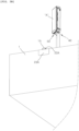
- FIGS. 1A to 1C are perspective views illustrating an installation state of various numbers of antenna devices using a mounting apparatus for an antenna device on a rooftop corner according to an embodiment of the present disclosure.
- FIG. 2 is a perspective view explaining an installation process of an antenna device using a bottom support part and a mounting part among constitutions of a mounting apparatus for an antenna device on a rooftop corner according to an embodiment of the present disclosure.
- FIGS. 3A and 3B are a downward perspective view and an upward perspective view illustrating an installation state of a single number of antenna devices at a corner of a rooftop.
- a mounting apparatus for an antenna device on a rooftop corner includes: a bottom support part 10 installed on a handrail 1 on a corner side of a rooftop, disposed on a bottom surface 2 on an inside adjacent to the handrail of the rooftop, and having a part extending upward in parallel to the handrail 1; a pair of handrail support parts 15, 21, and 27 extending horizontally from an upper part of the bottom support part 10 toward any one of the handrails 2 adjacent to each other; and a mounting part 40 and 50 coupled to the upper part of the bottom support part 10 and having a top on which the antenna device A is mounted.
- a single number of antenna device A may be coupled to an upper part of a single number of vertical support beam 13 to be described above, or as referenced in FIG. 1B , two antenna devices A1 and A2 may be coupled to the upper parts of the vertical support beam 13 through two branched antenna mounting beams 16, or as referenced in FIG. 1C , three antenna devices A1, A2, and A3 may be coupled to the upper part of the vertical support beam 13 through three branched antenna mounting beams 17.
- a front of the antenna device A is installed toward a corner side of the handrail 1 of the rooftop so that beamforming for a building outside direction is advantageous.
- the fronts of the antenna devices A1 and A2 may be installed in the same direction (refer to (a) of FIG. 1B ); or the fronts of the antenna devices A1 and A2 may be installed in the opposite directions, that is, any one antenna device A1 may be installed to face the corner side of the handrail 1 of the rooftop and the other antenna device A2 may be installed to face an inside of the rooftop (refer to (b) of FIG.
- the fronts of the antenna devices A1 and A2 may be installed to face different directions, that is, to face the directions at an angle of 45 degrees against the handrail 1 (refer to (c) of FIG. 1B ); or the fronts of the antenna devices A1 and A2 may be installed to face different directions, that is, to face the directions at an orthogonal angle against the handrail 1 (refer to (d) of FIG. 1B ).
- the three antenna devices A1, A2, and A3 can cover the forward angle of 120 degrees each within the omnidirectional beamforming angle range, and thus there is an advantage that the antenna devices A1, A2, and A3 can be disposed on the handrail 1 of the rooftop corner so that the fronts of the antenna devices face proper directions.
- the bottom support part 10 may include: a plurality of heavy object blocks 11; a lower support part 5, 6, and 7 disposed to be seated on an inner bottom surface 2 adjacent to the handrail 1 on the corner of the rooftop; and an upper support part 13 and 14 disposed on an upper part of the lower support part 5, 6, and 7.
- the plurality of heavy object blocks 11 may be provided as 10 or more heavy object blocks each having 30 kg so as to firmly support the weight more than 10 times the weight of the antenna device A on the bottom surface 2 on the inside of the rooftop without floating of the antenna device A.
- the number of heavy object blocks 11 is not necessarily limited thereto, and more or less than 10 heavy object blocks 11 can also be provided in consideration of the installation environment of the installed rooftop, such as wind volume and speed.
- each heavy object block 11 is 30 kg or less, even one worker can transport the heavy object block 11 by using the elevator or stairs in a building without the necessity of mobilizing heavy equipment, such as crane, and thus the installation cost and manpower can be saved.
- the mounting apparatus for an antenna device on a rooftop corner has been designed so that the weight of not only the plurality of heavy object blocks 11 but also individual constituent elements, such as the bottom support part 10 and the handrail support part 15, 21, and 27 belonging to other installation materials, does not exceed 30 kg so that it can be sufficiently transported using only one worker's manpower.
- the plurality of heavy object blocks 11 may be arranged in a long line so as to form one layer long in a predetermined direction on an upper part of a bottom support panel 6.
- the plurality of heavy object blocks 11 may be provided of a metal material of 30 kg or less, and can be individually seated on an upper surface of the bottom support panel 6 between a border frame 5 and a diagonal connection frame 7 among the constitutions of a lower support part 5, 6, and 7 to be described later.
- the plurality of heavy object blocks 11 may be manufactured with certain standards, and may be formed to be able to be stably stacked in the form that fits together like a block toys of LEGO Company.
- handle parts may be provided on the plurality of heavy object blocks 11 for stable transport by one installer, and the handle parts may be formed without interference during stacking of the plurality of heavy object blocks 11.
- the bottom support part 10 may serve to fix the antenna device A onto a top part of the support beam 13 with a height that satisfies the height regulations of the antenna device A.
- the height of the antenna device A can be adjusted by changing the installation location of the mounting part 40 and 50 against the vertical support beam 13 to be described later.
- the lower support part 5, 6, and 7 of the bottom support part 10 may include a bottom support panel 6 installed on the bottom surface 2 of the rooftop so that the plurality of heavy object blocks 11 are placed thereon, a border frame 5 configured to form a border end part of the bottom support panel 6, and a diagonal connection frame 7 cross-arranged to connect diagonal lines of the border frame 5.
- the bottom support panel 6 may be provided in the form of a roughly rectangular (or square) steel plate, and the border frame 5 may be provided with a rigid frame material connected to the border part of the bottom support panel 6 in any one of a welding coupling method and a bolting coupling method.
- the diagonal connection frame 7 may be provided with a rigid frame material cross-arranged to connect corner parts facing each other among corners of the bottom support panel 6 that is a rectangular (or square) steel plate with diagonal lines.
- a plurality of levelers configured to adjust balancing with respect to the bottom surface 2 of the rooftop may be provided on the lower part of the bottom support panel 6 or the border frame 5.
- the plurality of levelers may serve to help safe fixing and installation of the handrail support part 15, 21, and 27 on the handrail 1 on the corner of the rooftop after the balancing adjustment using the levelers.
- the upper support part 13 and 14 among the constitutions of the bottom support part 10 may include a vertical support beam 13 extending for a predetermined height from a crossing of the diagonal connection frame 7 in a vertical direction in parallel to the handrail 1, and at least two inclined support beams 14 each having a bottom connected to each middle part of the border frame 5 and a top extending to be inclined from the bottom and connected to a middle part of the vertical support beam 13.
- the bottom of the inclined support beam 14 is connected to each middle part of the border frame 5, and in case that four border frames 5 are provided to correspond to the number of sides of the rectangular bottom support panel 6, it is preferable that the number of inclined support beams 14 is also set to 4.
- the term "middle part” used herein does not mean only the accurately physically middle between both ends of the indicated constitution, but should be interpreted to include all of the remaining parts excluding one end part and the other end part in a state where the indicated constitution is divided into three equal parts.
- the upper support part 13 and 14 and the lower support part 5, 6, and 7 are provided with the rigid frame material (steel plate material) in all, and may be coupled to each other in any one of a welding coupling method and a bolting coupling method as one of methods suitable to the rigid frame material (or steel plate material) coupling methods.
- any one of the vertical support beam 13 and the at least two inclined support beams 14 may be provided with a communicable inner space, and a wire installation port (not illustrated) in which an external wire is inserted may be formed on a bottom part of any one of the at least two inclined support beams 14.
- the external wire is inserted and installed from the bottom surface 2 adjacent to the handrail 1 of the rooftop through the wire installation port of the inclined support beam 14, and is installed in a concealable manner to extend toward the installed antenna device A through the inner spaces of the inclined support beam 14 and the vertical support beam 13, it is possible to simplify the wiring design of the complicated external wire and to prevent the appearance beauty of the building from deteriorating due to the external wire.
- a pair of handrail support parts 15, 21, and 27 may include at least two horizontal support beams 15 horizontally extending from the middle part of the vertical support beam 13 toward top parts of the handrails 2 adjacent to each other, and extending from the vertical support beam 13 corresponding to the top part of the inclined support beam 14.
- the horizontal support beams 15 are provided one by one with respect to two adjacent handrails 1 having corners of 90 degrees, respectively, so that front end parts thereof are orthogonally seated by 90 degrees with respect to the two adjacent handrails 1.
- the at least two horizontal support beams 15 may be seated and coupled onto the seating panel part 21 so that the front end parts thereof support the weight of the seating panel part 21 to be described later in a gravity direction. This will be described in more detail later.
- FIGS. 4 and 5 are an exploded perspective view and a cross-sectional view illustrating a vibration reduction part among constitutions of a mounting apparatus for an antenna device on a rooftop corner according to an embodiment of the present disclosure.
- the pair of handrail support parts 15, 21, and 27 may further include: a seating panel part 21 coupled to surround the top part of the handrail 1; and a vibration reduction part 27 supported on an inner wall of the handrail 1.
- the seating panel part 21 may include: a top seating panel 22 configured to be seated on the top part of the handrail 1; a handrail close contact panel 23A extending to be bent from the top seating panel 22 and configured to come in close contact with an outer wall of the handrail 1; and a handrail spacing panel 23B extending to be bent from the top seating panel 22 and disposed in parallel to be spaced apart for a predetermined distance from the inner wall of the handrail 1.
- the handrail close contact panel 23A may be formed so that the end part of the top seating panel 22 in an outward direction of the handrail 1 is orthogonally bent downward
- the handrail spacing panel 23B may be formed so that the end part of the top seating panel 22 in an inward direction of the handrail 1 is orthogonally bent downward.
- the handrail close contact panel 23A of the seating panel part 21 may come in close contact with the outer wall of the handrail 1 and may have an area enough to endure the shaking (or gap) of the antenna device A caused by an external force, such as wind pressure, that is transferred to the antenna device A.
- the handrail close contact panel 23A may be formed with an area which is larger than the area of the handrail spacing panel 23B that is enough to install the vibration reduction part 27 to be described later thereon.
- the seating panel part 21 composed of the above-described constitution may be pre-assembled and fixed by the vibration reduction part 27 to be described later in a state where the horizontal support beam 15 is seated to surround the top part of the handrail 1 corresponding to an area that is orthogonal to the handrail 1, and the front end part of the horizontal support beam 15 may be fixed to the upper surface part.
- the seating panel part 21 may further include a pair of horizontal beam mounting ribs 22A formed integrally with the top seating panel 22 and configured to seat and surround a part of the front end part of the horizontal support beam 15.
- the pair of horizontal beam mounting ribs 22A may orthogonally extend upward with respect to the upper surface part of the top seating panel 22, and may be disposed in parallel to correspond to the length in the width direction of the horizontal support beam 15.
- the front end part of the horizontal support beam 15 may be seated, and although not illustrated, the front end part of the horizontal support beam 15 may be firmly fixed to the horizontal beam mounting rib 22A through a welding coupling method and a bolting coupling method.
- the vibration reduction part 27 may include: a clamping bolt 28 fastened to horizontally penetrate the handrail spacing panel 23B; a clamping nut 29 assembled to the clamping bolt 28; and an elastic part 30 provided on a front end part of the clamping bolt 28 and configured to be elastically supported on the inner wall of the corner side of the handrail 1.
- the elastic part 30 may be provided as a disc spring screw-fastened to a spring fastening hole (the reference numeral thereof is not denoted) provided on the front end part of the clamping bolt 28, the diameter of the disc spring becoming larger from a front end center of the clamping bolt 28 as getting closer toward the handrail 1.
- male threads (not illustrated) for the clamping nut 29 to be fastened thereto may be formed on an outer periphery of the clamping bolt 28, and after the clamping bolt 28 is penetratingly fastened to the handrail spacing panel 21a, the clamping nut 29 may be fastened to determine the tightening force in a screw connection method, and elastic part 30 may also be fastened to a screw fastening hole side provided with female threads on the front end part of the clamping bolt 28 in the screw connection method.
- the vibration reduction part 27 serves to make the handrail close contact panel 23A and the elastic part 30 be firmly and tightly clamped onto the inner wall and the outer wall of the handrail 1, respectively, when the clamping nut 29 is tightened.
- the vibration reduction part 27 may also serve to reduce external vibrations such as floating or shaking of the antenna device A caused by wind. That is, in case that the antenna device is installed on the handrail 1 constituting the corner of the rooftop, the antenna device A is subject to frequent wind pressure by usually strong winds, and the vibration reduction part 27 has the advantage of reducing the external vibrations and being able to block noise occurrence due to the vibrations in advance because the elastic part 30 is configured to be elastically supported on the handrail 1 against the floating or shaking of all constituent elements of the bottom support part 10 and the mounting part 40 and 50 including the antenna device A.
- FIG. 6 is a partial exploded perspective view and a partial enlarged view thereof illustrating a steering means of an antenna device
- FIGS. 7 and 8 are a partial exploded perspective view and a partial enlarged view thereof, and a cutaway perspective view illustrating a tilting means of an antenna device.
- the antenna device A may be mounted on the top part of the vertical support beam 13 through the mounting part 40 and 50 in tilting-rotatable and steering-rotatable manner.
- the mounting part 40 and 50 may include: a tilting means 40 configured to tilt and rotate the top part of the antenna device A coupled to the top part of the vertical support beam 13 in forward and backward direction centered on the bottom part of the antenna device A; and a steering means 50 configured to steer and rotate both left and right end parts of the antenna device A coupled to the top part of the vertical support beam 13 in left and right direction.
- the steering means 50 may include: a steering mounting panel 51 configured to mediate the coupling of the antenna device A onto the vertical support beam 13 and to be tilted in interworking with the tilting rotation of the antenna device A in forward and backward direction by the tilting means 40; a pair of left and right steering guide slots 52 penetratingly formed along a predetermined steering rotation trajectory in up and down direction of the steering mounting panel 51; and a pair of left and right steering guide bolts 53 configured to be fastened to a lower surface of the antenna device A through penetrating lower parts of the pair of left and right steering guide slots 52.
- the steering mounting panel 51 may be coupled to the top part of the vertical support beam 13 through a tilting rotation axis (not illustrated) that penetrates a tilting panel 41 and a tilting guide panel 43 of the tilting means 40 to be described later in left and right direction.
- the tilting means 40 may include: a hinge-fixed tilting panel 41 formed integrally with a lower surface of the steering mounting panel 51 provided to mediate the coupling of the antenna device A to the vertical support beam 13, and having a part configured to form a tilting rotation axis inside the vertical support beam 13; a pair of tilting guide panels 43 formed integrally with the lower surface of the steering mounting panel 51 on both left and right sides of the tilting panel 41 in parallel to the tilting panel 41; and a tilting adjustment bolt 45 connected to a bottom part of the tilting panel 41 and configured to adjust tilting of the tilting panel 41 at a predetermined angle in forward and backward direction.
- both end parts of the tilting rotation axis may be hinge-fixed to a tilting axis hole 49 formed on both left and right surfaces of the top part of the vertical support beam 13.
- worm wheel gear teeth 42 may be formed on an outer periphery of the bottom part of the tilting panel 41, and worm gear teeth 46 being tooth-engaged with the worm wheel gear teeth 42 of the tilting panel 41 may be formed on a part of the outer periphery of the tilting adjustment bolt 45.
- the tilting adjustment bolt 45 may be coupled to an inside of the top part of the vertical support beam 13 horizontally in forward and backward direction.
- the tilting adjustment bolt 45 may be provided with a tilting adjustment part (the reference numeral thereof is not denoted) configured to be exposed to the outside by penetrating the vertical support beam 13 corresponding to an inner direction of the handrail, and the tilting angle of the antenna device A may be adjusted in accordance with the rotation amount of the tilting adjustment bolt 45 through the tilting adjustment part.
- the tilting adjustment bolt 45 may have a front end part that is fixed to be rotatably supported on a hinge installation part 47A provided on the front end part of the vertical support beam 13, and a tilting adjustment part of a rear end part of the tilting adjustment bolt 45 may be installed to be exposed through penetrating the rear end part of the vertical support beam 13.
- a worker can adjust the tilting rotation angle of the antenna device A by setting the rotation amount of the tilting adjustment bolt 45 by using a predetermined adjustment tool that can rotate a head part (i.e., tilting adjustment part) of the bolt.
- the tilting means 40 may further include a tilting mounting panel 44 formed with a tilting slot 44A formed integrally with the top surface of the vertical support beam 13 and penetrated by the bottom part of the tilting panel 41 and a pair of tilting guide slots 44B penetrated by the bottom part of the pair of tilting guide panels 43.
- the tilting means 40 and the steering means 50 are disposed on the top part of the vertical support beam 13 which is relatively easy for an installation worker to access, they can provide the advantage for the installation worker or a manager of the antenna device A to be able to easily adjust the directivity of the antenna device A by using the tilting means 40 and the steering means 50.
- a control box C may be further installed in the middle area of the vertical support beam 13, and an optical cable A-3 that connects the control box C and the antenna device A with each other may be configured to penetrate up and down the steering mounting panel 51 and to be installed in a concealable manner from the outside by a concealing cover A-2 installed on the rear part of the antenna device A.
- the concealing cover A-2 may serve to prevent the worker or an unspecified person who can access the rooftop from coming in contact with a plurality of heat sink fins (the reference numeral thereof is not denoted) formed on the rear part of the antenna device A for system heat dissipation and getting burned, and at the same time, may serve not to spoil the appearance of a building including the antenna device A by making the optical cable A-3 be not exposed to the outside as described above.
- a plurality of air flowing holes A-2h capable of making an outdoor air flow therein may be formed to facilitate heat transfer to the outdoor air through the plurality of heat sink fins.
- the bottom of the concealing cover A-2 and the rear surface of the antenna device A may be disposed to be spaced apart for a predetermined distance from each other, or a through-installation port may be provided between them for installation of the optical cable A-3 therethrough.
- the mounting apparatus for an antenna device on a rooftop corner since the installation of the antenna device is possible through easy height adjustment of the bottom support part 10 even without shape change of the rooftop and easy clamping and bolting coupling against the handrail 1 on the corner side of the rooftop, the ease of installation can be improved, and various kinds of regulations in the country of installation can be satisfied.
- the mounting apparatus for an antenna device on a rooftop corner it is possible to install the plurality of antenna devices A and A1 to A3 by easily utilizing the spaces of the handrail 1 on the corner of the rooftop generally corresponding to surplus spaces, and the installation convenience can be improved by separating and coupling the weights of respective constitutions so as to be able to be transported by one worker or installer.
- the present disclosure provides a mounting apparatus for an antenna device on a rooftop corner, which enables the antenna device to be easily installed on a handrail of the rooftop corner without changes to the exterior of a building in a state where the installation height restrictions are satisfied in the corresponding installation country, facilitates installation of the antenna device on a top part of a holding pole, and enables concealable installation of a cable so as to prevent appearance beauty of the antenna device from deteriorating.
Landscapes
- Engineering & Computer Science (AREA)
- Computer Networks & Wireless Communication (AREA)
- Support Of Aerials (AREA)
Abstract
Description
- The present disclosure relates to a mounting apparatus for an antenna device on a rooftop corner, and more particularly, to a mounting apparatus for an antenna device on a rooftop corner, which enables the antenna device to be easily installed without physical changes to the exterior of a building in a state where the installation height restrictions are satisfied, enables concealable installation of an optical cable so that the optical cable is not exposed to outside, facilitates directivity adjustment of the antenna device, and does not require many workers.
- It is general to install an antenna for wireless communication in a high place where the surroundings are open for smooth transmission and reception with a wireless communication device that is located far away.
- For this, the antenna is installed on a utility pole, an iron tower, or a building roof (rooftop), and especially in a downtown area, the antenna is often installed on the rooftop.
- In this case, in order to install the antenna on the rooftop, a method is mainly used, in which a separate support pole for supporting the antenna in an upright state is installed on the building rooftop, and the antenna is fixed and installed onto the support pole.
- In this case, it is often considered that the support pole is mainly fixed and installed onto the floor surface of the rooftop by using an anchor and the like. However, in this case, it is required to drill into the floor of the rooftop in order to fix the support pole, and this necessarily entails the damage to the building. In addition, in case of installing the antenna on the building roof (rooftop), large transport machinery, such as crane, is required due to the considerable weight of installation materials including the support pole, and thus the installation cost is greatly increased.
- Further, in case that the antenna device is installed on the building rooftop, there is a problem in that various kinds of legal regulations of the corresponding installation country should be satisfied. For example, in order to install the antenna device on the building rooftop in a country, such as the US, it is required that the length in a diagonal direction of the antenna device does not exceed 3 ft so as to prevent accidents due to the collapse of the installation materials caused by strong wind pressure, and there are various kinds of regulations and diverse safety standards for operations of heavy equipment, such as large crane.
- The present disclosure has been devised to solve the above problems, and an object of the present disclosure is to provide a mounting apparatus for an antenna device on a rooftop corner, which enables the antenna device to be easily installed on a corner handrail of the rooftop without changes to the exterior of a building in a state where the installation height restrictions in the corresponding installation country are satisfied.
- Further, another object of the present disclosure is to provide a mounting apparatus for an antenna device on a rooftop corner, which facilitates installation of the antenna device on a top part of a holding pole, and enables concealable installation of a cable so as to prevent appearance beauty from deteriorating.
- In addition, still another object of the present disclosure is to provide a mounting apparatus for an antenna device on a rooftop corner, which facilitates directivity adjustment of the antenna device.
- The technical problems of the present disclosure are not limited to the above-described technical problems, and other unmentioned technical problems may be clearly understood by those skilled in the art from the following descriptions.
- A mounting apparatus for an antenna device on a rooftop corner according to an embodiment of the present disclosure includes: a bottom support part installed on a handrail on a corner side of a rooftop, disposed on a bottom surface on an inside of the handrail of the rooftop, and having a part extending upward in parallel to the handrail; a pair of handrail support parts extending horizontally from an upper part of the bottom support part toward the handrail, respectively; and a mounting part coupled to the upper part of the bottom support part and having a top on which the antenna device is mounted.
- Here, the bottom support part includes: a plurality of heavy object blocks; a lower support part including a bottom support panel installed on the bottom surface of the rooftop so that the plurality of heavy object blocks are placed thereon, a border frame configured to form a border end part of the bottom support panel, and a diagonal connection frame cross-arranged to connect diagonal lines of the border frame; and an upper support part including a vertical support beam extending for a predetermined height from a crossing of the diagonal connection frame in a vertical direction in parallel to the handrail, and at least two inclined support beams each having a bottom connected to each middle part of the border frame and a top extending to be inclined from the bottom and connected to a middle part of the vertical support beam.
- Further, the upper support part and the lower support part may be coupled to each other in any one of a welding coupling method and a bolting coupling method.
- Further, each of the plurality of heavy object blocks may be provided with a metal material of 3 kg or less, and may be able to be individually seated on an upper surface of the bottom support panel between the border frame and the diagonal connection frame.
- Further, any one of the vertical support beam and the at least two inclined support beams may be provided with a communicable inner space, and a wire installation port in which an external wire is inserted may be formed on a bottom part of any one of the at least two inclined support beams.
- Further, the pair of handrail support parts may include at least two horizontal support beams horizontally extending from the middle part of the vertical support beam toward top parts of the handrail adjacent to each other, and extending from top parts of the inclined support beams.
- Further, the pair of handrail support parts may further include: a seating panel part coupled to surround the top part of the handrail; and a vibration reduction part supported on an inner wall of the handrail.
- Further, the at least two horizontal support beams may be seated and coupled onto the seating panel part so that front end parts thereof support a weight of the seating panel part in a gravity direction.
- Further, the seating panel part may include: a top seating panel configured to be seated on the top part of the handrail; a handrail close contact panel extending to be bent from the top seating panel and configured to come in close contact with an outer wall of the handrail; and a handrail spacing panel extending to be bent from the top seating panel and disposed in parallel to be spaced apart for a predetermined distance from the inner wall of the handrail.
- Further, the seating panel part may further include a horizontal beam mounting rib formed integrally with the top seating panel and configured to seat and surround a part of a front end part of the horizontal support beam.
- Further, the vibration reduction part may include: a clamping bolt fastened to horizontally penetrate the handrail spacing panel disposed to be spaced apart from the inner wall of the handrail in parallel; a clamping nut assembled to the clamping bolt; and an elastic part provided on a front end part of the clamping bolt and configured to be elastically supported on the inner wall of the handrail.
- Further, the elastic part may be provided as a disc spring screw-fastened to a spring fastening hole provided on the front end part of the clamping bolt, a diameter of the disc spring becoming larger from a front end center of the clamping bolt as getting closer toward the handrail.
- Further, the mounting part may include: a tilting means configured to tilt and rotate a top part of the antenna device coupled to a top part of the vertical support beam in forward and backward direction centered on a bottom part thereof; and a steering means configured to steer and rotate both left and right end parts of the antenna device coupled to the top part of the vertical support beam in left and right direction.
- Further, the steering means may include: a steering mounting panel configured to mediate coupling of the antenna device to the vertical support beam and to be tilted in interwork with a tilting rotation of the antenna device in forward and backward direction by the tilting means; a pair of left and right steering guide slots penetratingly formed along a predetermined steering rotation trajectory in up and down direction of the steering mounting panel; and a pair of left and right steering guide bolts configured to be fastened to a lower surface of the antenna device through penetrating lower parts of the pair of left and right steering guide slots.
- Further, the steering mounting panel may be coupled to the top part of the vertical support beam through the tilting means.
- Further, the tilting means may include: a hinge-fixed tilting panel formed integrally with a lower surface of the steering mounting panel provided to mediate the coupling of the antenna device to the vertical support beam, and having a part configured to form a left and right tilting axis inside the vertical support beam; a pair of tilting guide panels formed integrally with the lower surface of the steering mounting panel on both left and right sides of the tilting panel in parallel to the tilting panel; and a tilting adjustment bolt connected to a bottom part of the tilting panel and configured to adjust tilting of the tilting panel at a predetermined angle in forward and backward direction.
- Further, worm wheel gear teeth may be formed on an outer periphery of the bottom part of the tilting panel, and a part of the outer periphery of the tilting adjustment bolt may be tooth-engaged with the worm wheel gear teeth; and the tilting adjustment bolt may be coupled to an inside of the top part of the vertical support beam horizontally in forward and backward direction.
- Further, the tilting adjustment bolt may be provided with a tilting adjustment part configured to be exposed to outside by penetrating the vertical support beam corresponding to an inner direction of the handrail, and a tilting angle of the antenna device may be adjusted in accordance with a rotation amount of the tilting adjustment bolt through the tiling adjustment part.
- Further, the tilting means may further include a tilting mounting panel formed with a tilting slot formed integrally with a top surface of the vertical support beam and penetrated by a bottom part of the tilting panel and a pair of tilting guide slots penetrated by a bottom part of the pair of tilting guide panels.
- Further, a control box may be further installed on a middle area of the vertical support beam, and an optical cable that connects the control box and the antenna device with each other may be configured to penetrate up and down the steering mounting panel and to be installed in a concealable manner from the outside by a concealing cover installed on a rear part of the antenna device.
- According to the mounting apparatus for an antenna device on a rooftop corner according to an embodiment of the present disclosure, it is possible to easily install the antenna device on the handrail of the rooftop corner without changes to the exterior of a building in a state where the installation height restrictions in the corresponding country of installation are satisfied.
- Further, according to the present disclosure, since it is possible to install the optical cable without being exposed to the outside, the appearance beauty can be improved.
- In addition, according to the present disclosure, manual adjustment is easy in adjusting directivity of the antenna device.
-
-
FIGS. 1A to 1C are perspective views illustrating an installation state of various numbers of antenna devices using a mounting apparatus for an antenna device on a rooftop corner according to an embodiment of the present disclosure. -
FIG. 2 is a perspective view explaining an installation process of an antenna device using a bottom support part and a mounting part among constitutions of a mounting apparatus for an antenna device on a rooftop corner according to an embodiment of the present disclosure. -
FIGS. 3A and3B are a downward perspective view and an upward perspective view illustrating an installation state of a single number of antenna devices at a corner of a rooftop. -
FIGS. 4 and5 are an exploded perspective view and a cross-sectional view illustrating a vibration reduction part among constitutions of a mounting apparatus for an antenna device on a rooftop corner according to an embodiment of the present disclosure. -
FIG. 6 is a partial exploded perspective view and a partial enlarged view thereof illustrating a steering means of an antenna device. -
FIGS. 7 and8 are a partial exploded perspective view and a partial enlarged view thereof, and a cutaway perspective view illustrating a tilting means of an antenna device. -
1: handrail 2: bottom surface 5: border frame 6: bottom support panel 7: diagonal connection frame 10: bottom support part 11: heavy object block 13: vertical support beam 14: inclined support beam 15: horizontal support beam 15, 21, 27: handrail support part 21: seating panel part 22: top seating panel 22A: horizontal beam mounting rib 23A: handrail close contact panel 23B: handrail spacing panel 27: vibration reduction part 23B: clamping bolt 29: clamping nut 28: elastic part 40: tilting means 30: tilting panel 42: worm wheel gear teeth 41: tilting guide panel 44: tilting mounting panel 43: tilting slot 44B: tilting guide slot 44A: tilting adjustment bolt 46: worm gear teeth 45: hinge installation part 49: tilting axis hole 47A: steering means 51: steering mounting panel 50: steering guide slot 53: steering guide bolt 52: - Hereinafter, a mounting apparatus for an antenna device on a rooftop corner according to an embodiment of the present disclosure will be described in detail with reference to the exemplary drawings.
- In adding reference numerals to constituent elements in the drawings, it is to be noted that the same constituent elements have the same reference numerals as much as possible even if they are represented in different drawings. Further, in explaining embodiments of the present disclosure, the detailed explanation of related known constitutions or functions will be omitted if it is determined that the detailed explanation interferes with understanding of the embodiments of the present disclosure.
- The terms, such as "first, second, A, B, (a), and (b)", may be used to describe constituent elements of embodiments of the present disclosure. The terms are only for the purpose of discriminating one constituent element from another constituent element, but the nature, the turn, or the order of the corresponding constituent elements is not limited by the terms. Further, unless otherwise defined, all terms (including technical and scientific terms) used herein have the same meanings as those commonly understood by those ordinary skilled in the art to which the present disclosure belongs. The terms that are defined in a generally used dictionary should be interpreted as meanings that match with the meanings of the terms from the context of the related technology, and they are not interpreted as an ideal or excessively formal meaning unless clearly defined in the present disclosure.
-
FIGS. 1A to 1C are perspective views illustrating an installation state of various numbers of antenna devices using a mounting apparatus for an antenna device on a rooftop corner according to an embodiment of the present disclosure.FIG. 2 is a perspective view explaining an installation process of an antenna device using a bottom support part and a mounting part among constitutions of a mounting apparatus for an antenna device on a rooftop corner according to an embodiment of the present disclosure.FIGS. 3A and3B are a downward perspective view and an upward perspective view illustrating an installation state of a single number of antenna devices at a corner of a rooftop. - As referenced in
FIGS. 1 to 3B , a mounting apparatus for an antenna device on a rooftop corner according to an embodiment of the present disclosure includes: abottom support part 10 installed on ahandrail 1 on a corner side of a rooftop, disposed on abottom surface 2 on an inside adjacent to the handrail of the rooftop, and having a part extending upward in parallel to thehandrail 1; a pair ofhandrail support parts bottom support part 10 toward any one of thehandrails 2 adjacent to each other; and a mountingpart bottom support part 10 and having a top on which the antenna device A is mounted. - Here, as for the antenna device A, as referenced in
FIG. 1A , a single number of antenna device A may be coupled to an upper part of a single number ofvertical support beam 13 to be described above, or as referenced inFIG. 1B , two antenna devices A1 and A2 may be coupled to the upper parts of thevertical support beam 13 through two branchedantenna mounting beams 16, or as referenced inFIG. 1C , three antenna devices A1, A2, and A3 may be coupled to the upper part of thevertical support beam 13 through three branched antenna mounting beams 17. - As referenced in
FIG. 1A , in case that the single number of antenna device A is coupled to the upper part of thevertical support beam 13, it is preferable that a front of the antenna device A is installed toward a corner side of thehandrail 1 of the rooftop so that beamforming for a building outside direction is advantageous. - Further, as referenced in
FIG. 1B , in case that two antenna devices A1 and A2 are coupled to two branchedantenna mounting beams 16, the fronts of the antenna devices A1 and A2 may be installed in the same direction (refer to (a) ofFIG. 1B ); or the fronts of the antenna devices A1 and A2 may be installed in the opposite directions, that is, any one antenna device A1 may be installed to face the corner side of thehandrail 1 of the rooftop and the other antenna device A2 may be installed to face an inside of the rooftop (refer to (b) ofFIG. 1B ); or the fronts of the antenna devices A1 and A2 may be installed to face different directions, that is, to face the directions at an angle of 45 degrees against the handrail 1 (refer to (c) ofFIG. 1B ); or the fronts of the antenna devices A1 and A2 may be installed to face different directions, that is, to face the directions at an orthogonal angle against the handrail 1 (refer to (d) ofFIG. 1B ). - Further, as referenced in
FIG. 1C , in case that three antenna devices A1, A2, and A3 are coupled to three branchedantenna mounting beams 17, the three antenna devices A1, A2, and A3 can cover the forward angle of 120 degrees each within the omnidirectional beamforming angle range, and thus there is an advantage that the antenna devices A1, A2, and A3 can be disposed on thehandrail 1 of the rooftop corner so that the fronts of the antenna devices face proper directions. - In addition, as referenced in
FIGS. 3A and3B , almost all constituent elements of thebottom support part 10 excluding a top part of thevertical support beam 13 and the antenna device A installed thereon are installed with heights which are lower than or roughly the same as the top height of the handrail 1 (in case ofhandrail support part handrail 1. - Meanwhile, as referenced in
FIG. 2 , thebottom support part 10 may include: a plurality of heavy object blocks 11; alower support part inner bottom surface 2 adjacent to thehandrail 1 on the corner of the rooftop; and anupper support part lower support part - Here, for example, if the weight of the antenna device A is 30 kg, the plurality of heavy object blocks 11 may be provided as 10 or more heavy object blocks each having 30 kg so as to firmly support the weight more than 10 times the weight of the antenna device A on the
bottom surface 2 on the inside of the rooftop without floating of the antenna device A. However, the number of heavy object blocks 11 is not necessarily limited thereto, and more or less than 10 heavy object blocks 11 can also be provided in consideration of the installation environment of the installed rooftop, such as wind volume and speed. - In particular, if the weight of each
heavy object block 11 is 30 kg or less, even one worker can transport theheavy object block 11 by using the elevator or stairs in a building without the necessity of mobilizing heavy equipment, such as crane, and thus the installation cost and manpower can be saved. - The mounting apparatus for an antenna device on a rooftop corner according to an embodiment of the present disclosure has been designed so that the weight of not only the plurality of heavy object blocks 11 but also individual constituent elements, such as the
bottom support part 10 and thehandrail support part - Further, as illustrated in
FIG. 2 , the plurality of heavy object blocks 11 may be arranged in a long line so as to form one layer long in a predetermined direction on an upper part of abottom support panel 6. - More specifically, as referenced in (b) of
FIG. 2 , the plurality of heavy object blocks 11 may be provided of a metal material of 30 kg or less, and can be individually seated on an upper surface of thebottom support panel 6 between aborder frame 5 and adiagonal connection frame 7 among the constitutions of alower support part - In addition, although not illustrated in the drawing, the plurality of heavy object blocks 11 may be manufactured with certain standards, and may be formed to be able to be stably stacked in the form that fits together like a block toys of LEGO Company. In this case, handle parts may be provided on the plurality of heavy object blocks 11 for stable transport by one installer, and the handle parts may be formed without interference during stacking of the plurality of heavy object blocks 11.
- Meanwhile, the
bottom support part 10 may serve to fix the antenna device A onto a top part of thesupport beam 13 with a height that satisfies the height regulations of the antenna device A. Here, the height of the antenna device A can be adjusted by changing the installation location of the mountingpart vertical support beam 13 to be described later. - More specifically, as referenced in (a) to (c) of
FIG. 2 , thelower support part bottom support part 10 may include abottom support panel 6 installed on thebottom surface 2 of the rooftop so that the plurality of heavy object blocks 11 are placed thereon, aborder frame 5 configured to form a border end part of thebottom support panel 6, and adiagonal connection frame 7 cross-arranged to connect diagonal lines of theborder frame 5. - The
bottom support panel 6 may be provided in the form of a roughly rectangular (or square) steel plate, and theborder frame 5 may be provided with a rigid frame material connected to the border part of thebottom support panel 6 in any one of a welding coupling method and a bolting coupling method. Thediagonal connection frame 7 may be provided with a rigid frame material cross-arranged to connect corner parts facing each other among corners of thebottom support panel 6 that is a rectangular (or square) steel plate with diagonal lines. - Here, although not illustrated in the drawing, a plurality of levelers configured to adjust balancing with respect to the
bottom surface 2 of the rooftop may be provided on the lower part of thebottom support panel 6 or theborder frame 5. After thelower support part bottom surface 2 of the rooftop, the plurality of levelers may serve to help safe fixing and installation of thehandrail support part handrail 1 on the corner of the rooftop after the balancing adjustment using the levelers. - Meanwhile, as referenced in (c) of
FIG. 2 , theupper support part bottom support part 10 may include avertical support beam 13 extending for a predetermined height from a crossing of thediagonal connection frame 7 in a vertical direction in parallel to thehandrail 1, and at least two inclined support beams 14 each having a bottom connected to each middle part of theborder frame 5 and a top extending to be inclined from the bottom and connected to a middle part of thevertical support beam 13. - The bottom of the
inclined support beam 14 is connected to each middle part of theborder frame 5, and in case that fourborder frames 5 are provided to correspond to the number of sides of the rectangularbottom support panel 6, it is preferable that the number of inclined support beams 14 is also set to 4. - Meanwhile, the term "middle part" used herein does not mean only the accurately physically middle between both ends of the indicated constitution, but should be interpreted to include all of the remaining parts excluding one end part and the other end part in a state where the indicated constitution is divided into three equal parts.
- Here, the
upper support part lower support part - Meanwhile, although not illustrated in detail in the drawing, any one of the
vertical support beam 13 and the at least two inclined support beams 14 may be provided with a communicable inner space, and a wire installation port (not illustrated) in which an external wire is inserted may be formed on a bottom part of any one of the at least two inclined support beams 14. - As described above, since the external wire is inserted and installed from the
bottom surface 2 adjacent to thehandrail 1 of the rooftop through the wire installation port of theinclined support beam 14, and is installed in a concealable manner to extend toward the installed antenna device A through the inner spaces of theinclined support beam 14 and thevertical support beam 13, it is possible to simplify the wiring design of the complicated external wire and to prevent the appearance beauty of the building from deteriorating due to the external wire. - Meanwhile, as referenced in (d) and (e) of
FIG. 2 , a pair ofhandrail support parts vertical support beam 13 toward top parts of thehandrails 2 adjacent to each other, and extending from thevertical support beam 13 corresponding to the top part of theinclined support beam 14. - It is preferable that the horizontal support beams 15 are provided one by one with respect to two
adjacent handrails 1 having corners of 90 degrees, respectively, so that front end parts thereof are orthogonally seated by 90 degrees with respect to the twoadjacent handrails 1. - In this case, the at least two horizontal support beams 15 may be seated and coupled onto the
seating panel part 21 so that the front end parts thereof support the weight of theseating panel part 21 to be described later in a gravity direction. This will be described in more detail later. -
FIGS. 4 and5 are an exploded perspective view and a cross-sectional view illustrating a vibration reduction part among constitutions of a mounting apparatus for an antenna device on a rooftop corner according to an embodiment of the present disclosure. - As referenced in
FIGS. 4 and5 , the pair ofhandrail support parts seating panel part 21 coupled to surround the top part of thehandrail 1; and avibration reduction part 27 supported on an inner wall of thehandrail 1. - Here, as referenced in
FIGS. 4 and5 , theseating panel part 21 may include: atop seating panel 22 configured to be seated on the top part of thehandrail 1; a handrailclose contact panel 23A extending to be bent from thetop seating panel 22 and configured to come in close contact with an outer wall of thehandrail 1; and ahandrail spacing panel 23B extending to be bent from thetop seating panel 22 and disposed in parallel to be spaced apart for a predetermined distance from the inner wall of thehandrail 1. - The handrail
close contact panel 23A may be formed so that the end part of thetop seating panel 22 in an outward direction of thehandrail 1 is orthogonally bent downward, and thehandrail spacing panel 23B may be formed so that the end part of thetop seating panel 22 in an inward direction of thehandrail 1 is orthogonally bent downward. - The handrail
close contact panel 23A of theseating panel part 21 may come in close contact with the outer wall of thehandrail 1 and may have an area enough to endure the shaking (or gap) of the antenna device A caused by an external force, such as wind pressure, that is transferred to the antenna device A. - Accordingly, the handrail
close contact panel 23A may be formed with an area which is larger than the area of thehandrail spacing panel 23B that is enough to install thevibration reduction part 27 to be described later thereon. - The
seating panel part 21 composed of the above-described constitution may be pre-assembled and fixed by thevibration reduction part 27 to be described later in a state where thehorizontal support beam 15 is seated to surround the top part of thehandrail 1 corresponding to an area that is orthogonal to thehandrail 1, and the front end part of thehorizontal support beam 15 may be fixed to the upper surface part. - For this, as referenced in
FIGS. 4 and5 , theseating panel part 21 may further include a pair of horizontalbeam mounting ribs 22A formed integrally with thetop seating panel 22 and configured to seat and surround a part of the front end part of thehorizontal support beam 15. - The pair of horizontal
beam mounting ribs 22A may orthogonally extend upward with respect to the upper surface part of thetop seating panel 22, and may be disposed in parallel to correspond to the length in the width direction of thehorizontal support beam 15. - Between the pair of horizontal
beam mounting ribs 22A, the front end part of thehorizontal support beam 15 may be seated, and although not illustrated, the front end part of thehorizontal support beam 15 may be firmly fixed to the horizontalbeam mounting rib 22A through a welding coupling method and a bolting coupling method. - Meanwhile, as referenced in
FIGS. 4 and5 , thevibration reduction part 27 may include: a clampingbolt 28 fastened to horizontally penetrate thehandrail spacing panel 23B; a clampingnut 29 assembled to the clampingbolt 28; and anelastic part 30 provided on a front end part of the clampingbolt 28 and configured to be elastically supported on the inner wall of the corner side of thehandrail 1. - Here, the
elastic part 30 may be provided as a disc spring screw-fastened to a spring fastening hole (the reference numeral thereof is not denoted) provided on the front end part of the clampingbolt 28, the diameter of the disc spring becoming larger from a front end center of the clampingbolt 28 as getting closer toward thehandrail 1. - As referenced in
FIGS. 4 and5 , according to thevibration reduction part 27 composed of the above-described constitution, male threads (not illustrated) for the clampingnut 29 to be fastened thereto may be formed on an outer periphery of the clampingbolt 28, and after theclamping bolt 28 is penetratingly fastened to the handrail spacing panel 21a, the clampingnut 29 may be fastened to determine the tightening force in a screw connection method, andelastic part 30 may also be fastened to a screw fastening hole side provided with female threads on the front end part of the clampingbolt 28 in the screw connection method. - The
vibration reduction part 27 serves to make the handrailclose contact panel 23A and theelastic part 30 be firmly and tightly clamped onto the inner wall and the outer wall of thehandrail 1, respectively, when the clampingnut 29 is tightened. - Here, since the
elastic part 30 is provided to be elastically supported on the inner wall of thehandrail 1, thevibration reduction part 27 may also serve to reduce external vibrations such as floating or shaking of the antenna device A caused by wind. That is, in case that the antenna device is installed on thehandrail 1 constituting the corner of the rooftop, the antenna device A is subject to frequent wind pressure by usually strong winds, and thevibration reduction part 27 has the advantage of reducing the external vibrations and being able to block noise occurrence due to the vibrations in advance because theelastic part 30 is configured to be elastically supported on thehandrail 1 against the floating or shaking of all constituent elements of thebottom support part 10 and the mountingpart -
FIG. 6 is a partial exploded perspective view and a partial enlarged view thereof illustrating a steering means of an antenna device, andFIGS. 7 and8 are a partial exploded perspective view and a partial enlarged view thereof, and a cutaway perspective view illustrating a tilting means of an antenna device. - As referenced in
FIGS. 6 to 8 , the antenna device A may be mounted on the top part of thevertical support beam 13 through the mountingpart - Here, as referenced in
FIGS. 6 to 8 , the mountingpart vertical support beam 13 in forward and backward direction centered on the bottom part of the antenna device A; and a steering means 50 configured to steer and rotate both left and right end parts of the antenna device A coupled to the top part of thevertical support beam 13 in left and right direction. - The steering means 50 may include: a
steering mounting panel 51 configured to mediate the coupling of the antenna device A onto thevertical support beam 13 and to be tilted in interworking with the tilting rotation of the antenna device A in forward and backward direction by the tilting means 40; a pair of left and rightsteering guide slots 52 penetratingly formed along a predetermined steering rotation trajectory in up and down direction of thesteering mounting panel 51; and a pair of left and rightsteering guide bolts 53 configured to be fastened to a lower surface of the antenna device A through penetrating lower parts of the pair of left and rightsteering guide slots 52. - Here, the
steering mounting panel 51 may be coupled to the top part of thevertical support beam 13 through a tilting rotation axis (not illustrated) that penetrates a tiltingpanel 41 and a tilting guide panel 43 of the tilting means 40 to be described later in left and right direction. - Meanwhile, as referenced in
FIGS. 6 to 8 , the tilting means 40 may include: a hinge-fixedtilting panel 41 formed integrally with a lower surface of thesteering mounting panel 51 provided to mediate the coupling of the antenna device A to thevertical support beam 13, and having a part configured to form a tilting rotation axis inside thevertical support beam 13; a pair of tilting guide panels 43 formed integrally with the lower surface of thesteering mounting panel 51 on both left and right sides of the tiltingpanel 41 in parallel to the tiltingpanel 41; and atilting adjustment bolt 45 connected to a bottom part of the tiltingpanel 41 and configured to adjust tilting of the tiltingpanel 41 at a predetermined angle in forward and backward direction. - Here, both end parts of the tilting rotation axis (not illustrated) may be hinge-fixed to a tilting
axis hole 49 formed on both left and right surfaces of the top part of thevertical support beam 13. - In addition, worm
wheel gear teeth 42 may be formed on an outer periphery of the bottom part of the tiltingpanel 41, andworm gear teeth 46 being tooth-engaged with the wormwheel gear teeth 42 of the tiltingpanel 41 may be formed on a part of the outer periphery of the tiltingadjustment bolt 45. - The tilting
adjustment bolt 45 may be coupled to an inside of the top part of thevertical support beam 13 horizontally in forward and backward direction. - Further, the tilting
adjustment bolt 45 may be provided with a tilting adjustment part (the reference numeral thereof is not denoted) configured to be exposed to the outside by penetrating thevertical support beam 13 corresponding to an inner direction of the handrail, and the tilting angle of the antenna device A may be adjusted in accordance with the rotation amount of the tiltingadjustment bolt 45 through the tilting adjustment part. - More specifically, the tilting
adjustment bolt 45 may have a front end part that is fixed to be rotatably supported on ahinge installation part 47A provided on the front end part of thevertical support beam 13, and a tilting adjustment part of a rear end part of the tiltingadjustment bolt 45 may be installed to be exposed through penetrating the rear end part of thevertical support beam 13. - Here, a worker can adjust the tilting rotation angle of the antenna device A by setting the rotation amount of the tilting
adjustment bolt 45 by using a predetermined adjustment tool that can rotate a head part (i.e., tilting adjustment part) of the bolt. - Meanwhile, the tilting means 40 may further include a tilting mounting panel 44 formed with a tilting slot 44A formed integrally with the top surface of the
vertical support beam 13 and penetrated by the bottom part of the tiltingpanel 41 and a pair of tilting guide slots 44B penetrated by the bottom part of the pair of tilting guide panels 43. - Here, since the tilting means 40 and the steering means 50 are disposed on the top part of the
vertical support beam 13 which is relatively easy for an installation worker to access, they can provide the advantage for the installation worker or a manager of the antenna device A to be able to easily adjust the directivity of the antenna device A by using the tilting means 40 and the steering means 50. - Meanwhile, a control box C may be further installed in the middle area of the
vertical support beam 13, and an optical cable A-3 that connects the control box C and the antenna device A with each other may be configured to penetrate up and down thesteering mounting panel 51 and to be installed in a concealable manner from the outside by a concealing cover A-2 installed on the rear part of the antenna device A. - Here, the concealing cover A-2 may serve to prevent the worker or an unspecified person who can access the rooftop from coming in contact with a plurality of heat sink fins (the reference numeral thereof is not denoted) formed on the rear part of the antenna device A for system heat dissipation and getting burned, and at the same time, may serve not to spoil the appearance of a building including the antenna device A by making the optical cable A-3 be not exposed to the outside as described above.
- On the concealing cover A-2, a plurality of air flowing holes A-2h capable of making an outdoor air flow therein may be formed to facilitate heat transfer to the outdoor air through the plurality of heat sink fins.
- Further, the bottom of the concealing cover A-2 and the rear surface of the antenna device A may be disposed to be spaced apart for a predetermined distance from each other, or a through-installation port may be provided between them for installation of the optical cable A-3 therethrough.
- As described above, according to the mounting apparatus for an antenna device on a rooftop corner according to an embodiment of the present disclosure, since the installation of the antenna device is possible through easy height adjustment of the
bottom support part 10 even without shape change of the rooftop and easy clamping and bolting coupling against thehandrail 1 on the corner side of the rooftop, the ease of installation can be improved, and various kinds of regulations in the country of installation can be satisfied. - Further, according to an embodiment of the mounting apparatus for an antenna device on a rooftop corner according to the present disclosure, it is possible to install the plurality of antenna devices A and A1 to A3 by easily utilizing the spaces of the
handrail 1 on the corner of the rooftop generally corresponding to surplus spaces, and the installation convenience can be improved by separating and coupling the weights of respective constitutions so as to be able to be transported by one worker or installer. - As above, a mounting apparatus for an antenna device on a rooftop corner according to an embodiment of the present disclosure has been described in detail with reference to the accompanying drawings. However, embodiments of the present disclosure are not necessarily limited to the above-described embodiment, but it will be apparent that various modifications and implementation within an equal scope are possible by those of ordinary skill in the art to which the present disclosure pertains. Accordingly, the true scope of the present disclosure should be determined by the appended claims.
- The present disclosure provides a mounting apparatus for an antenna device on a rooftop corner, which enables the antenna device to be easily installed on a handrail of the rooftop corner without changes to the exterior of a building in a state where the installation height restrictions are satisfied in the corresponding installation country, facilitates installation of the antenna device on a top part of a holding pole, and enables concealable installation of a cable so as to prevent appearance beauty of the antenna device from deteriorating.
Claims (20)
- A mounting apparatus for an antenna device on a rooftop corner, the mounting apparatus comprising:a bottom support part installed on a handrail on a corner side of a rooftop, disposed on a bottom surface on an inside of the handrail of the rooftop, and having a part extending upward in parallel to the handrail;a pair of handrail support parts extending horizontally from an upper part of the bottom support part toward the handrail, respectively; anda mounting part coupled to the upper part of the bottom support part and having a top on which the antenna device is mounted.
- The mounting apparatus of claim 1, wherein the bottom support part comprises:a plurality of heavy object blocks;a lower support part including a bottom support panel installed on the bottom surface of the rooftop so that the plurality of heavy object blocks are placed thereon, a border frame configured to form a border end part of the bottom support panel, and a diagonal connection frame cross-arranged to connect diagonal lines of the border frame; andan upper support part including a vertical support beam extending for a predetermined height from a crossing of the diagonal connection frame in a vertical direction in parallel to the handrail, and at least two inclined support beams each having a bottom connected to each middle part of the border frame and a top extending to be inclined from the bottom and connected to a middle part of the vertical support beam.
- The mounting apparatus of claim 2, wherein the upper support part and the lower support part are coupled to each other in any one of a welding coupling method and a bolting coupling method.
- The mounting apparatus of claim 2, wherein each of the plurality of heavy object blocks is provided with a metal material of 30 kg or less, and is able to be individually seated on an upper surface of the bottom support panel between the border frame and the diagonal connection frame.
- The mounting apparatus of claim 2, wherein any one of the vertical support beam and the at least two inclined support beams is provided with a communicable inner space, and
a wire installation port in which an external wire is inserted is formed on a bottom part of any one of the at least two inclined support beams. - The mounting apparatus of claim 2, wherein the pair of handrail support parts comprises at least two horizontal support beams horizontally extending from the middle part of the vertical support beam toward top parts of the handrail adjacent to each other, and extending from top parts of the inclined support beams.
- The mounting apparatus of claim 6, wherein the pair of handrail support parts further comprises:a seating panel part coupled to surround the top part of the handrail; anda vibration reduction part supported on an inner wall of the handrail.
- The mounting apparatus of claim 7, wherein the at least two horizontal support beams are seated and coupled onto the seating panel part so that front end parts thereof support a weight of the seating panel part in a gravity direction.
- The mounting apparatus of claim 7, wherein the seating panel part comprises:a top seating panel configured to be seated on the top part of the handrail;a handrail close contact panel extending to be bent from the top seating panel and configured to come in close contact with an outer wall of the handrail; anda handrail spacing panel extending to be bent from the top seating panel and disposed in parallel to be spaced apart for a predetermined distance from the inner wall of the handrail.
- The mounting apparatus of claim 9, wherein the seating panel part further comprises a horizontal beam mounting rib formed integrally with the top seating panel and configured to seat and surround a part of a front end part of the horizontal support beam.
- The mounting apparatus of claim 7, wherein the vibration reduction part comprises:a clamping bolt fastened to horizontally penetrate the handrail spacing panel disposed to be spaced apart from the inner wall of the handrail in parallel;a clamping nut assembled to the clamping bolt; andan elastic part provided on a front end part of the clamping bolt and configured to be elastically supported on the inner wall of the handrail.
- The mounting apparatus of claim 11, wherein the elastic part is provided as a disc spring screw-fastened to a spring fastening hole provided on the front end part of the clamping bolt, a diameter of the disc spring becoming larger from a front end center of the clamping bolt as getting closer toward the handrail.
- The mounting apparatus of claim 2, wherein the mounting part comprises:a tilting means configured to tilt and rotate a top part of the antenna device coupled to a top part of the vertical support beam in forward and backward direction centered on a bottom part thereof; anda steering means configured to steer and rotate both left and right end parts of the antenna device coupled to the top part of the vertical support beam in left and right direction.
- The mounting apparatus of claim 13, wherein the steering means comprises:a steering mounting panel configured to mediate coupling of the antenna device to the vertical support beam and to be tilted in interwork with a tilting rotation of the antenna device in forward and backward direction by the tilting means;a pair of left and right steering guide slots penetratingly formed along a predetermined steering rotation trajectory in up and down direction of the steering mounting panel; anda pair of left and right steering guide bolts configured to be fastened to a lower surface of the antenna device through penetrating lower parts of the pair of left and right steering guide slots.
- The mounting apparatus of claim 14, wherein the steering mounting panel is coupled to the top part of the vertical support beam through the tilting means.
- The mounting apparatus of claim 13, wherein the tilting means comprises:a hinge-fixed tilting panel formed integrally with a lower surface of the steering mounting panel provided to mediate the coupling of the antenna device to the vertical support beam, and having a part configured to form a tilting rotation axis inside the vertical support beam;a pair of tilting guide panels formed integrally with the lower surface of the steering mounting panel on both left and right sides of the tilting panel in parallel to the tilting panel; anda tilting adjustment bolt connected to a bottom part of the tilting panel and configured to adjust tilting of the tilting panel at a predetermined angle in forward and backward direction.
- The mounting apparatus of claim 16, wherein worm wheel gear teeth are formed on an outer periphery of the bottom part of the tilting panel, and a part of the outer periphery of the tilting adjustment bolt is tooth-engaged with the worm wheel gear teeth; and
wherein the tilting adjustment bolt is coupled to an inside of the top part of the vertical support beam horizontally in forward and backward direction. - The mounting apparatus of claim 16, wherein the tilting adjustment bolt is provided with a tilting adjustment part configured to be exposed to outside by penetrating the vertical support beam corresponding to an inner direction of the handrail, and
wherein a tilting angle of the antenna device is adjusted in accordance with a rotation amount of the tilting adjustment bolt through the tilting adjustment part. - The mounting apparatus of claim 16, wherein the tilting means further comprises a tilting mounting panel formed with a tilting slot formed integrally with a top surface of the vertical support beam and penetrated by a bottom part of the tilting panel and a pair of tilting guide slots penetrated by a bottom part of the pair of tilting guide panels.
- The mounting apparatus of claim 14, wherein a control box is further installed on a middle area of the vertical support beam, and
wherein an optical cable that connects the control box and the antenna device with each other is configured to penetrate up and down the steering mounting panel and to be installed in a concealable manner from the outside by a concealing cover installed on a rear part of the antenna device.
Applications Claiming Priority (3)
| Application Number | Priority Date | Filing Date | Title |
|---|---|---|---|
| KR20210079657 | 2021-06-18 | ||
| KR1020220073263A KR20220169908A (en) | 2021-06-18 | 2022-06-16 | Mounting apparatus for antenna device on rooftop conner |
| PCT/KR2022/008588 WO2022265444A1 (en) | 2021-06-18 | 2022-06-17 | Mounting apparatus for antenna device on rooftop conner |
Publications (2)
| Publication Number | Publication Date |
|---|---|
| EP4358291A1 true EP4358291A1 (en) | 2024-04-24 |
| EP4358291A4 EP4358291A4 (en) | 2025-07-16 |
Family
ID=84526704
Family Applications (1)
| Application Number | Title | Priority Date | Filing Date |
|---|---|---|---|
| EP22825367.0A Pending EP4358291A4 (en) | 2021-06-18 | 2022-06-17 | MOUNTING DEVICE FOR AN ANTENNA DEVICE ON A ROOF CARRIER |
Country Status (5)
| Country | Link |
|---|---|
| US (1) | US20240128631A1 (en) |
| EP (1) | EP4358291A4 (en) |
| JP (1) | JP7654836B2 (en) |
| CN (1) | CN218677537U (en) |
| WO (1) | WO2022265444A1 (en) |
Families Citing this family (1)
| Publication number | Priority date | Publication date | Assignee | Title |
|---|---|---|---|---|
| CN118472633B (en) * | 2024-06-25 | 2024-10-15 | 中瀚天成(北京)科技有限公司 | Protection structure of signal seal control interference device and signal seal control interference device |
Family Cites Families (12)
| Publication number | Priority date | Publication date | Assignee | Title |
|---|---|---|---|---|
| JPS60149217U (en) * | 1984-03-12 | 1985-10-03 | 福伸電機株式会社 | antenna mount |
| JP2611806B2 (en) * | 1988-05-27 | 1997-05-21 | 永楽産業 株式会社 | Building rooftop antenna pole establishment device |
| JP4426043B2 (en) * | 2000-01-11 | 2010-03-03 | マスプロ電工株式会社 | Antenna support device |
| JP2003070134A (en) * | 2001-08-24 | 2003-03-07 | Wireless Engineering Kk | Wiring construction method on the rooftop |
| JP5699011B2 (en) * | 2011-03-23 | 2015-04-08 | Necネッツエスアイ株式会社 | Support pillar and its installation method |
| JP2013005300A (en) * | 2011-06-17 | 2013-01-07 | Cosmo System Kk | Communication instrument frame and radio base station |
| KR101431243B1 (en) * | 2014-05-09 | 2014-08-18 | (주)비디씨 | Fence for Antenna of base station |
| JP6151390B1 (en) * | 2016-02-10 | 2017-06-21 | レンドリース・ジャパン株式会社 | Communication device mount and radio base station |
| KR101926109B1 (en) * | 2018-05-29 | 2018-12-06 | 정윤범 | Antenna mounting device with easy control of slant |
| KR102633259B1 (en) * | 2018-08-27 | 2024-02-05 | 주식회사 케이엠더블유 | Structure for antenna installation |
| CN209249666U (en) * | 2018-12-29 | 2019-08-13 | 北京市光环电信股份有限公司 | Outdoor Antenna Guards |
| CN209249680U (en) * | 2018-12-29 | 2019-08-13 | 北京市光环电信股份有限公司 | A kind of exterior aerial protective device |
-
2022
- 2022-06-17 WO PCT/KR2022/008588 patent/WO2022265444A1/en not_active Ceased
- 2022-06-17 CN CN202221525679.2U patent/CN218677537U/en active Active
- 2022-06-17 JP JP2023577398A patent/JP7654836B2/en active Active
- 2022-06-17 EP EP22825367.0A patent/EP4358291A4/en active Pending
-
2023
- 2023-12-18 US US18/542,903 patent/US20240128631A1/en active Pending
Also Published As
| Publication number | Publication date |
|---|---|
| JP7654836B2 (en) | 2025-04-01 |
| EP4358291A4 (en) | 2025-07-16 |
| JP2024523319A (en) | 2024-06-28 |
| US20240128631A1 (en) | 2024-04-18 |
| WO2022265444A1 (en) | 2022-12-22 |
| CN218677537U (en) | 2023-03-21 |
Similar Documents
| Publication | Publication Date | Title |
|---|---|---|
| KR100984339B1 (en) | Variable geometry curtain wall fastner | |
| US7659865B2 (en) | Adjustable fast set antenna frame | |
| US20240128631A1 (en) | Mounting apparatus for antenna device on looptop conner | |
| KR102399730B1 (en) | Connecting unit for modular structure and modular structure construction methode using the same | |
| US20240136707A1 (en) | Mounting apparatus for antenna device on rooftop | |
| KR20220169908A (en) | Mounting apparatus for antenna device on rooftop conner | |
| US9328504B2 (en) | Divider wall connection systems and methods | |
| US12146324B2 (en) | Solar cell module installation structure, house, and solar cell module | |
| US20240136697A1 (en) | Mounting apparatus for antenna device on rooftop | |
| CN117916950A (en) | Installation device of antenna equipment for roof corner | |
| KR20220168563A (en) | Mounting apparatus for antenna device on rooftop | |
| JP3197997B2 (en) | Mountable mounting table for equipment | |
| JP2005299247A (en) | Method of fixing facility structure | |
| US20250043572A1 (en) | Direct mount wall screen | |
| CN219448961U (en) | Large-area outdoor sightseeing elevator | |
| JPWO2021229695A5 (en) | ||
| JPH08165720A (en) | Unit type building and construction method thereof | |
| JP2019127772A (en) | Stair structure and unit building | |
| JP3001605U (en) | Curtain wall unit mounting hardware | |
| JPS5968489A (en) | Attachment of bow window | |
| JPH10169051A (en) | Exterior wall panel mounting structure | |
| JP2021088898A (en) | Cornice prevention device | |
| JPH10140719A (en) | Inclined fastener | |
| JPH0913558A (en) | Mounting structure for external wall panel | |
| JPH06212704A (en) | Unit type building |
Legal Events
| Date | Code | Title | Description |
|---|---|---|---|
| STAA | Information on the status of an ep patent application or granted ep patent |
Free format text: STATUS: THE INTERNATIONAL PUBLICATION HAS BEEN MADE |
|
| PUAI | Public reference made under article 153(3) epc to a published international application that has entered the european phase |
Free format text: ORIGINAL CODE: 0009012 |
|
| STAA | Information on the status of an ep patent application or granted ep patent |
Free format text: STATUS: REQUEST FOR EXAMINATION WAS MADE |
|
| 17P | Request for examination filed |
Effective date: 20231218 |
|
| AK | Designated contracting states |
Kind code of ref document: A1 Designated state(s): AL AT BE BG CH CY CZ DE DK EE ES FI FR GB GR HR HU IE IS IT LI LT LU LV MC MK MT NL NO PL PT RO RS SE SI SK SM TR |
|
| DAV | Request for validation of the european patent (deleted) | ||
| DAX | Request for extension of the european patent (deleted) | ||
| A4 | Supplementary search report drawn up and despatched |
Effective date: 20250612 |
|
| RIC1 | Information provided on ipc code assigned before grant |
Ipc: H01Q 1/12 20060101AFI20250606BHEP Ipc: F16B 2/06 20060101ALI20250606BHEP Ipc: H01Q 1/24 20060101ALI20250606BHEP Ipc: F16B 7/18 20060101ALN20250606BHEP |