EP4358275A1 - Current collector, battery cover, and battery structure - Google Patents
Current collector, battery cover, and battery structure Download PDFInfo
- Publication number
- EP4358275A1 EP4358275A1 EP22829537.4A EP22829537A EP4358275A1 EP 4358275 A1 EP4358275 A1 EP 4358275A1 EP 22829537 A EP22829537 A EP 22829537A EP 4358275 A1 EP4358275 A1 EP 4358275A1
- Authority
- EP
- European Patent Office
- Prior art keywords
- connection portion
- current collector
- cover plate
- top cover
- electrode post
- Prior art date
- Legal status (The legal status is an assumption and is not a legal conclusion. Google has not performed a legal analysis and makes no representation as to the accuracy of the status listed.)
- Pending
Links
Images

Classifications
-
- H—ELECTRICITY
- H01—ELECTRIC ELEMENTS
- H01M—PROCESSES OR MEANS, e.g. BATTERIES, FOR THE DIRECT CONVERSION OF CHEMICAL ENERGY INTO ELECTRICAL ENERGY
- H01M4/00—Electrodes
- H01M4/02—Electrodes composed of, or comprising, active material
- H01M4/64—Carriers or collectors
- H01M4/70—Carriers or collectors characterised by shape or form
- H01M4/75—Wires, rods or strips
-
- H—ELECTRICITY
- H01—ELECTRIC ELEMENTS
- H01M—PROCESSES OR MEANS, e.g. BATTERIES, FOR THE DIRECT CONVERSION OF CHEMICAL ENERGY INTO ELECTRICAL ENERGY
- H01M4/00—Electrodes
- H01M4/02—Electrodes composed of, or comprising, active material
- H01M4/64—Carriers or collectors
- H01M4/70—Carriers or collectors characterised by shape or form
-
- H—ELECTRICITY
- H01—ELECTRIC ELEMENTS
- H01M—PROCESSES OR MEANS, e.g. BATTERIES, FOR THE DIRECT CONVERSION OF CHEMICAL ENERGY INTO ELECTRICAL ENERGY
- H01M50/00—Constructional details or processes of manufacture of the non-active parts of electrochemical cells other than fuel cells, e.g. hybrid cells
- H01M50/10—Primary casings; Jackets or wrappings
- H01M50/147—Lids or covers
-
- H—ELECTRICITY
- H01—ELECTRIC ELEMENTS
- H01M—PROCESSES OR MEANS, e.g. BATTERIES, FOR THE DIRECT CONVERSION OF CHEMICAL ENERGY INTO ELECTRICAL ENERGY
- H01M50/00—Constructional details or processes of manufacture of the non-active parts of electrochemical cells other than fuel cells, e.g. hybrid cells
- H01M50/10—Primary casings; Jackets or wrappings
- H01M50/172—Arrangements of electric connectors penetrating the casing
-
- H—ELECTRICITY
- H01—ELECTRIC ELEMENTS
- H01M—PROCESSES OR MEANS, e.g. BATTERIES, FOR THE DIRECT CONVERSION OF CHEMICAL ENERGY INTO ELECTRICAL ENERGY
- H01M50/00—Constructional details or processes of manufacture of the non-active parts of electrochemical cells other than fuel cells, e.g. hybrid cells
- H01M50/10—Primary casings; Jackets or wrappings
- H01M50/172—Arrangements of electric connectors penetrating the casing
- H01M50/174—Arrangements of electric connectors penetrating the casing adapted for the shape of the cells
- H01M50/179—Arrangements of electric connectors penetrating the casing adapted for the shape of the cells for cells having curved cross-section, e.g. round or elliptic
-
- H—ELECTRICITY
- H01—ELECTRIC ELEMENTS
- H01M—PROCESSES OR MEANS, e.g. BATTERIES, FOR THE DIRECT CONVERSION OF CHEMICAL ENERGY INTO ELECTRICAL ENERGY
- H01M50/00—Constructional details or processes of manufacture of the non-active parts of electrochemical cells other than fuel cells, e.g. hybrid cells
- H01M50/10—Primary casings; Jackets or wrappings
- H01M50/183—Sealing members
- H01M50/186—Sealing members characterised by the disposition of the sealing members
- H01M50/188—Sealing members characterised by the disposition of the sealing members the sealing members being arranged between the lid and terminal
-
- H—ELECTRICITY
- H01—ELECTRIC ELEMENTS
- H01M—PROCESSES OR MEANS, e.g. BATTERIES, FOR THE DIRECT CONVERSION OF CHEMICAL ENERGY INTO ELECTRICAL ENERGY
- H01M50/00—Constructional details or processes of manufacture of the non-active parts of electrochemical cells other than fuel cells, e.g. hybrid cells
- H01M50/50—Current conducting connections for cells or batteries
- H01M50/502—Interconnectors for connecting terminals of adjacent batteries; Interconnectors for connecting cells outside a battery casing
-
- H—ELECTRICITY
- H01—ELECTRIC ELEMENTS
- H01M—PROCESSES OR MEANS, e.g. BATTERIES, FOR THE DIRECT CONVERSION OF CHEMICAL ENERGY INTO ELECTRICAL ENERGY
- H01M50/00—Constructional details or processes of manufacture of the non-active parts of electrochemical cells other than fuel cells, e.g. hybrid cells
- H01M50/50—Current conducting connections for cells or batteries
- H01M50/531—Electrode connections inside a battery casing
- H01M50/533—Electrode connections inside a battery casing characterised by the shape of the leads or tabs
-
- H—ELECTRICITY
- H01—ELECTRIC ELEMENTS
- H01M—PROCESSES OR MEANS, e.g. BATTERIES, FOR THE DIRECT CONVERSION OF CHEMICAL ENERGY INTO ELECTRICAL ENERGY
- H01M50/00—Constructional details or processes of manufacture of the non-active parts of electrochemical cells other than fuel cells, e.g. hybrid cells
- H01M50/50—Current conducting connections for cells or batteries
- H01M50/543—Terminals
-
- H—ELECTRICITY
- H01—ELECTRIC ELEMENTS
- H01M—PROCESSES OR MEANS, e.g. BATTERIES, FOR THE DIRECT CONVERSION OF CHEMICAL ENERGY INTO ELECTRICAL ENERGY
- H01M50/00—Constructional details or processes of manufacture of the non-active parts of electrochemical cells other than fuel cells, e.g. hybrid cells
- H01M50/50—Current conducting connections for cells or batteries
- H01M50/543—Terminals
- H01M50/552—Terminals characterised by their shape
- H01M50/559—Terminals adapted for cells having curved cross-section, e.g. round, elliptic or button cells
-
- H—ELECTRICITY
- H01—ELECTRIC ELEMENTS
- H01M—PROCESSES OR MEANS, e.g. BATTERIES, FOR THE DIRECT CONVERSION OF CHEMICAL ENERGY INTO ELECTRICAL ENERGY
- H01M50/00—Constructional details or processes of manufacture of the non-active parts of electrochemical cells other than fuel cells, e.g. hybrid cells
- H01M50/10—Primary casings; Jackets or wrappings
- H01M50/102—Primary casings; Jackets or wrappings characterised by their shape or physical structure
- H01M50/107—Primary casings; Jackets or wrappings characterised by their shape or physical structure having curved cross-section, e.g. round or elliptic
-
- H—ELECTRICITY
- H01—ELECTRIC ELEMENTS
- H01M—PROCESSES OR MEANS, e.g. BATTERIES, FOR THE DIRECT CONVERSION OF CHEMICAL ENERGY INTO ELECTRICAL ENERGY
- H01M50/00—Constructional details or processes of manufacture of the non-active parts of electrochemical cells other than fuel cells, e.g. hybrid cells
- H01M50/10—Primary casings; Jackets or wrappings
- H01M50/147—Lids or covers
- H01M50/148—Lids or covers characterised by their shape
- H01M50/152—Lids or covers characterised by their shape for cells having curved cross-section, e.g. round or elliptic
-
- H—ELECTRICITY
- H01—ELECTRIC ELEMENTS
- H01M—PROCESSES OR MEANS, e.g. BATTERIES, FOR THE DIRECT CONVERSION OF CHEMICAL ENERGY INTO ELECTRICAL ENERGY
- H01M50/00—Constructional details or processes of manufacture of the non-active parts of electrochemical cells other than fuel cells, e.g. hybrid cells
- H01M50/10—Primary casings; Jackets or wrappings
- H01M50/183—Sealing members
- H01M50/186—Sealing members characterised by the disposition of the sealing members
-
- Y—GENERAL TAGGING OF NEW TECHNOLOGICAL DEVELOPMENTS; GENERAL TAGGING OF CROSS-SECTIONAL TECHNOLOGIES SPANNING OVER SEVERAL SECTIONS OF THE IPC; TECHNICAL SUBJECTS COVERED BY FORMER USPC CROSS-REFERENCE ART COLLECTIONS [XRACs] AND DIGESTS
- Y02—TECHNOLOGIES OR APPLICATIONS FOR MITIGATION OR ADAPTATION AGAINST CLIMATE CHANGE
- Y02E—REDUCTION OF GREENHOUSE GAS [GHG] EMISSIONS, RELATED TO ENERGY GENERATION, TRANSMISSION OR DISTRIBUTION
- Y02E60/00—Enabling technologies; Technologies with a potential or indirect contribution to GHG emissions mitigation
- Y02E60/10—Energy storage using batteries
Definitions
- the present disclosure relates to the field of battery technologies, and in particular to a current collector, a battery cover plate, and a battery structure.
- the current collector is adopted with the form of metal sheet, with an end connected to a winding core, the other end fixed with a cover plate assembly, and the middle portion in the form of different shapes of the overall metal sheet.
- the bending position is prone to stress concentration, resulting in the fracture of the current collector.
- the present disclosure provides a current collector, a battery cover, and a battery structure, which improves the bending resistance of the current collector by arranging a bending-resistant portion in the current collector on the basis of ensuring the current-passing capability.
- the present disclosure provides a current collector, including a first connection portion, a bending-resistant portion, and a second connection portion; wherein the first connection portion and the second connection portion are connected through the bending-resistant portion.
- the bending-resistant portion is a plurality of metal wires evenly distributed; a first end of each metal wire is connected to the first connection portion, and a second end of each metal wire is connected to the second connection portion.
- the bend-resistant portion is a bendable metal wavy plate; a first end of the metal wavy plate is connected to the first connection portion, and a second end of the metal wavy plate is connected to the second connection portion.
- peaks and valleys on the metal wavy plate are alternately arranged from the first connection portion to the second connection portion.
- an outer side of the bending-resistant portion is covered with an insulating layer.
- first connection portion and the second connection portion are metal sheets with smooth surfaces.
- a battery cover plate including:
- the top cover plate includes a recessed portion, an upper plastic is arranged in the recessed portion, and the upper plastic defines an upper plastic hole communicated with the top cover through hole; the electrode post body penetrates the upper plastic hole to be connected to the terminal; the upper plastic is arranged with a plastic protrusion abutting against the terminal.
- the upper plastic is circumferentially arranged with a plastic raised portion along an outer end of the upper plastic, and an inner wall of the plastic raised portion abuts against a circumferential outer wall of the terminal.
- the battery cover plate further includes: a lower plastic, arranged between the top cover plate and the current collector; wherein the lower plastic defines a lower plastic hole, and the electrode post body is connected to the terminal through the lower plastic hole.
- the battery cover plate further includes: a sealing ring, sleeved on and connected to the electrode post body; wherein the sealing ring includes a ring body and a protruding portion perpendicular to the ring body; the protruding portion is arranged in the top cover through hole, arranged between the electrode post body and the top cover through hole, and held by the electrode post body and a side wall of the top cover through hole; the ring body is arranged between the electrode post holder and a bottom surface of the top cover plate and is held by the electrode post holder and the top cover plate.
- the present disclosure provides a battery structure, including the battery cover plate as above.
- the bending portion may not be damaged due to a concentrated stress of the current collector when bending, thereby improving the bending resistance of the current collector, increasing the bending toughness of the bending portion, preventing the current collector from breaking during the use of the battery, and thus enhancing the stability of the battery during use.
- the terms “coupled”, “connected”, “fixed” are to be understood in a broad sense, for example, as a fixed connection, as a removable connection, or as a one-piece unit; as a mechanical connection or as an electrical connection; as a direct connection or as an indirect connection through an intermediate medium; as an internal connection of two components or an interaction of two components.
- the meaning of the above terms in the context of the present disclosure may be understood in accordance with the circumstances.
- a first feature "on” or “under” a second feature may include direct contact between the first and second features, or it may include contact between the first and second features not directly, but through a separate feature between them.
- the first feature being “above”, “on” and “on top of” the second feature includes the first feature being directly above and diagonally above the second feature, or simply indicating that the first feature is horizontally higher than the second feature.
- the first feature being “below”, “under” and “on bottom of” the second feature includes the first feature being directly below and diagonally below the second feature, or simply indicating that the first feature is horizontally lower than the second feature.
- embodiments of the present disclosure provide a current collector, and the current collector 7 includes a first connection portion 71, a bending-resistant portion 72, and a second connection portion 73.
- the first connection portion 71 and the second connection portion 73 are connected through the bending-resistant portion 72.
- the bending portion 72 may not be damaged due to a concentrated stress of the current collector 7 when bending, thereby improving the bending resistance of the current collector 7, increasing the bending toughness of the bending portion 72, preventing the current collector 7 from breaking during the use of the battery, and thus enhancing the stability of the battery during use.
- the current collector 7 includes a bendable portion.
- the current collector 7 includes a first connection portion 71 and a second connection portion 73.
- the first connection portion 71 and the second connection portion 73 are metal sheets with smooth surfaces. The flat structure of the sheet may increase the welding joints during welding and enhance the current-passing capability.
- the first connection portion 71 and the second connection portion 73 may be made of aluminum or copper and other metal materials.
- the first connection portion 71 and the second connection portion 73 are connected through the bending-resistant portion 72.
- An outer side of the bending-resistant portion 72 is covered with an insulating layer, which may relieve the bending fatigue of the bending-resistant portion 72.
- the insulating layer may be made of PTE, PA, and other insulating plastic.
- the bending-resistant portion 72 is multiple metal wires evenly distributed, and the metal wires are made of metal materials such as aluminum or copper. A first end of each metal wire is connected to the first connection portion 71, and a second end of the metal wire is connected to the second connection portion 73.
- the metal wires are evenly distributed between the first connection portion 71 and the second connection portion 73 to connect the first connection portion 71 and the second connection portion 73, such that the subjected force is uniform when bending; in addition, a stress concentration in the bending portion may be avoided when bending, thereby increasing the bending capacity of the current collector 7.
- the bending-resistant portion 72 may be integrally formed with the first connection portion 71 and the second connection portion 73, i.e., aluminum or copper may be integrally formed into the current collector 7, and then cut into multiple wires at the bending portion to reduce processes of connecting the bending-resistant portion 72 with the first connection portion 71 and the second connection portion 73, such that the bending-resistant portion 72 is not easy to break at connection ends.
- the bend-resistant portion 72 is a bendable metal wavy plate, and a first end of the metal wavy plate is connected to the first connection portion 71 and a second end of the metal wavy plate is connected to the second connection portion 73.
- peaks and valleys on the metal wavy plate are alternately arranged from the first connection portion 71 to the second connection portion 73, such that the bend-resistant portion 72 can be easily bent to avoid breaking.
- the length of the metal wavy plate is 1/3 to 1/2 of the length D of the current collector 7, (where: the length of the metal wavy plate refers to the distance from a connection point of the metal wavy plate with the first connection section 71 to a connection point with the second connection section 73).
- the metal wavy plate, the first connection portion 71, and the second connection portion 73 are integrally formed, and the metal wavy plate may be formed by pressing, thereby reducing processes of connecting the bending-resistant portion 72 with the first connection portion 71 and the second connection portion 73, such that the bending-resistant portion 72 is not easy to break at connection ends.
- embodiments of the present disclosure further provide a battery cover plate, the battery cover plate includes the above-mentioned current collector 7, an electrode post 2, and a top cover plate 5.
- the electrode post 2 includes an electrode post holder 22 and an electrode post body 21.
- the top cover plate 5 defines a top cover through hole 51; the electrode post body 21 is connected to a terminal 1 through the top cover through hole 51.
- the battery cover plate further includes a sealing ring 4, which is sleeved on and connected to the electrode post body 21.
- the sealing ring 4 includes a ring body 42 and a protruding portion 41 perpendicular to the ring body 42.
- the protruding portion 41 is arranged in the top cover through hole 51, arranged between the electrode post body 21 and the top cover through hole 51, and held by the electrode post body 21 and a side wall of the top cover through hole 51, thereby effectively realizing isolation and sealing between the electrode post body 21 and the top cover plate 5.
- the ring body 42 is arranged between the electrode post holder 22 and a bottom surface of the top cover plate 5 and is held by the electrode post holder 22 and the top cover plate 5, thereby effectively realizing isolation and sealing between the electrode post holder 22 and the top cover plate 5.
- the sealing ring 4 is made of a resilient rubber material.
- the top cover plate 5 includes a recessed portion 52, the recessed portion 52 is arranged with an upper plastic 3, and the upper plastic 3 defines an upper plastic hole 31 coaxial with the top cover through hole 51.
- the electrode post body 21 penetrates the upper plastic hole 31 to be connected to the terminal 1.
- the upper plastic 3 in the recessed portion 52 may increase the seal of the electrode post body 21 through the top cover through hole 51, such that the top cover plate 5 and the terminal 1 are combined more closely.
- the upper plastic 3 is arranged with a plastic protrusion 32, which abuts against the terminal 1 to prevent the terminal 1 from shaking with respect to the top cover plate 5.
- the upper plastic 3 is circumferentially arranged with a plastic raised portion 33 along an outer end of the upper plastic 3, and an inner wall of the plastic raised portion 33 abuts against a circumferential outer wall of the terminal 1.
- the plastic raised portion 33 enclosing the outer circumferential wall of the terminal 1 may avoid the risk of contact between the terminal 1 and the top cover plate 5.
- the battery cover plate further includes a lower plastic 6, which is arranged under the top cover plate 5, and the lower plastic 6 defines a lower plastic hole 61.
- the electrode post body 21 is connected to the terminal 1 through the lower plastic hole 61.
- the current collector 7 and the terminal 1 are disposed on opposite sides of the top cover plate 5, respectively, and the current collector 7 is disposed under the lower plastic 6.
- the first connection portion 71 of the current collector 7 is connected to the electrode post holder 22.
- the lower plastic 6 further defines a passage port 62 on a side wall of the lower plastic 6 for the current collector 7 to pass through, and the second connection portion 73 can pass through the passage port 62 to be connected to a winding core in subsequent processes.
- Embodiments of the present disclosure further provide a battery structure, including the above-mentioned battery cover plate, in order to enhance the bending resistance at the bending portion of the current collector 7 on the basis of ensuring the current-passing capability, thereby enhancing the stability of the battery during use.
Landscapes
- Chemical & Material Sciences (AREA)
- Chemical Kinetics & Catalysis (AREA)
- Electrochemistry (AREA)
- General Chemical & Material Sciences (AREA)
- Connection Of Batteries Or Terminals (AREA)
Abstract
Description
- The present application claims priority of
Chinese Patent Application No. 202222404648.8, filed on September 09, 2022 - The present disclosure relates to the field of battery technologies, and in particular to a current collector, a battery cover plate, and a battery structure.
- In the relevant cylindrical battery electrical connection technologies, the current collector is adopted with the form of metal sheet, with an end connected to a winding core, the other end fixed with a cover plate assembly, and the middle portion in the form of different shapes of the overall metal sheet. During the bending process of the current collector, the bending position is prone to stress concentration, resulting in the fracture of the current collector. In the actual use of the finished battery, there will be excessive vibration amplitude and frequency that will lead to the fracture of the current collector, which will directly cause breakage of the battery's internal circuit.
- The present disclosure provides a current collector, a battery cover, and a battery structure, which improves the bending resistance of the current collector by arranging a bending-resistant portion in the current collector on the basis of ensuring the current-passing capability.
- In a first aspect, the present disclosure provides a current collector, including a first connection portion, a bending-resistant portion, and a second connection portion; wherein the first connection portion and the second connection portion are connected through the bending-resistant portion.
- In some embodiments, the bending-resistant portion is a plurality of metal wires evenly distributed; a first end of each metal wire is connected to the first connection portion, and a second end of each metal wire is connected to the second connection portion.
- In some embodiments, the bend-resistant portion is a bendable metal wavy plate; a first end of the metal wavy plate is connected to the first connection portion, and a second end of the metal wavy plate is connected to the second connection portion.
- In some embodiments, peaks and valleys on the metal wavy plate are alternately arranged from the first connection portion to the second connection portion.
- In some embodiments, an outer side of the bending-resistant portion is covered with an insulating layer.
- In some embodiments, the first connection portion and the second connection portion are metal sheets with smooth surfaces.
- In a second aspect, the present disclosure provides a battery cover plate, including:
- the current collector as above;
- an electrode post, including an electrode post holder and an electrode post body;
- a top cover plate, defining a top cover through hole; and
- a terminal; wherein the electrode post body is connected to the terminal through the top cover through hole; the terminal is disposed on a side of the top cover plate; and the current collector is disposed on another side, opposite to the side, of the top cover plate;
- wherein the first connection portion of the current collector is connected to the electrode post holder.
- In some embodiments, the top cover plate includes a recessed portion, an upper plastic is arranged in the recessed portion, and the upper plastic defines an upper plastic hole communicated with the top cover through hole; the electrode post body penetrates the upper plastic hole to be connected to the terminal; the upper plastic is arranged with a plastic protrusion abutting against the terminal.
- In some embodiments, the upper plastic is circumferentially arranged with a plastic raised portion along an outer end of the upper plastic, and an inner wall of the plastic raised portion abuts against a circumferential outer wall of the terminal.
- In some embodiments, the battery cover plate further includes: a lower plastic, arranged between the top cover plate and the current collector; wherein the lower plastic defines a lower plastic hole, and the electrode post body is connected to the terminal through the lower plastic hole.
- In some embodiments, the battery cover plate further includes: a sealing ring, sleeved on and connected to the electrode post body; wherein the sealing ring includes a ring body and a protruding portion perpendicular to the ring body; the protruding portion is arranged in the top cover through hole, arranged between the electrode post body and the top cover through hole, and held by the electrode post body and a side wall of the top cover through hole; the ring body is arranged between the electrode post holder and a bottom surface of the top cover plate and is held by the electrode post holder and the top cover plate.
- In a third aspect, the present disclosure provides a battery structure, including the battery cover plate as above.
- Beneficial effect of the present disclosure.
- On the basis of ensuring the current-passing capacity, by arranging the bending-resistant portion in the current collector, the bending portion may not be damaged due to a concentrated stress of the current collector when bending, thereby improving the bending resistance of the current collector, increasing the bending toughness of the bending portion, preventing the current collector from breaking during the use of the battery, and thus enhancing the stability of the battery during use.
-
-
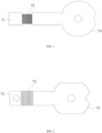
FIG. 1 is a structural schematic view of a current collector in which a bending portion is a metal wire according to an embodiment of the present disclosure. -
FIG. 2 is a structural schematic view of a current collector in which a bending portion is a metal wavy plate according to an embodiment of the present disclosure. -
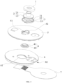
FIG. 3 is an exploded schematic view of a battery cover plate according to an embodiment of the present disclosure. -
FIG. 4 is a cross-sectional schematic view of a battery cover plate according to an embodiment of the present disclosure. - Reference numerals:
- 1-terminal; 2-electrode post; 21-electrode post body; 22-electrode post holder; 3-upper plastic; 31-upper plastic hole; 32-plastic protrusion; 33-plastic raised portion; 4-sealing ring; 41-protruding portion; 42-ring body; 5-top cover plate; 51-top cover through hole; 52-recessed portion; 6-lower plastic; 61-lower plastic hole; 62-passage port; 7-current collector; 71-first connection portion 72-bending-resistant portion; 73-second connection portion.
- In the description of the present disclosure, unless otherwise specified and limited, the terms "coupled", "connected", "fixed" are to be understood in a broad sense, for example, as a fixed connection, as a removable connection, or as a one-piece unit; as a mechanical connection or as an electrical connection; as a direct connection or as an indirect connection through an intermediate medium; as an internal connection of two components or an interaction of two components. To those skilled in the art, the meaning of the above terms in the context of the present disclosure may be understood in accordance with the circumstances.
- In the present disclosure, unless otherwise expressly specified and limited, a first feature "on" or "under" a second feature may include direct contact between the first and second features, or it may include contact between the first and second features not directly, but through a separate feature between them. Also, the first feature being "above", "on" and "on top of" the second feature includes the first feature being directly above and diagonally above the second feature, or simply indicating that the first feature is horizontally higher than the second feature. The first feature being "below", "under" and "on bottom of" the second feature includes the first feature being directly below and diagonally below the second feature, or simply indicating that the first feature is horizontally lower than the second feature.
- In the description herein, the terms "up", "down", "left", "right", and other orientation or positional relationships are based on the orientation or positional relationships shown in the accompanying drawings and are intended only to facilitate description and simplify operation, not to indicate or imply that the device or element referred to must have a particular orientation, be constructed and operate in a particular orientation, and therefore are not to be construed as limiting the present disclosure. In addition, the terms "first" and "second" are used only for descriptive distinction and have no special meaning.
- As shown in
FIGS. 1-2 , embodiments of the present disclosure provide a current collector, and thecurrent collector 7 includes afirst connection portion 71, a bending-resistant portion 72, and asecond connection portion 73. Thefirst connection portion 71 and thesecond connection portion 73 are connected through the bending-resistant portion 72. - On the basis of ensuring the current-passing capacity, by arranging the bending-
resistant portion 72 in the current collector, thebending portion 72 may not be damaged due to a concentrated stress of thecurrent collector 7 when bending, thereby improving the bending resistance of thecurrent collector 7, increasing the bending toughness of thebending portion 72, preventing thecurrent collector 7 from breaking during the use of the battery, and thus enhancing the stability of the battery during use. - The following is a detailed description of the embodiments, as shown in
FIGS. 1 and 2 , thecurrent collector 7 includes a bendable portion. Exemplarily, thecurrent collector 7 includes afirst connection portion 71 and asecond connection portion 73. In some embodiments, thefirst connection portion 71 and thesecond connection portion 73 are metal sheets with smooth surfaces. The flat structure of the sheet may increase the welding joints during welding and enhance the current-passing capability. In some embodiments, thefirst connection portion 71 and thesecond connection portion 73 may be made of aluminum or copper and other metal materials. Thefirst connection portion 71 and thesecond connection portion 73 are connected through the bending-resistant portion 72. An outer side of the bending-resistant portion 72 is covered with an insulating layer, which may relieve the bending fatigue of the bending-resistant portion 72. The insulating layer may be made of PTE, PA, and other insulating plastic. - As shown in
FIG. 1 , in some embodiments, the bending-resistant portion 72 is multiple metal wires evenly distributed, and the metal wires are made of metal materials such as aluminum or copper. A first end of each metal wire is connected to thefirst connection portion 71, and a second end of the metal wire is connected to thesecond connection portion 73. The metal wires are evenly distributed between thefirst connection portion 71 and thesecond connection portion 73 to connect thefirst connection portion 71 and thesecond connection portion 73, such that the subjected force is uniform when bending; in addition, a stress concentration in the bending portion may be avoided when bending, thereby increasing the bending capacity of thecurrent collector 7. The bending-resistant portion 72 may be integrally formed with thefirst connection portion 71 and thesecond connection portion 73, i.e., aluminum or copper may be integrally formed into thecurrent collector 7, and then cut into multiple wires at the bending portion to reduce processes of connecting the bending-resistant portion 72 with thefirst connection portion 71 and thesecond connection portion 73, such that the bending-resistant portion 72 is not easy to break at connection ends. - As shown in
FIG. 2 , in other embodiments, as shown inFIG. 4 , the bend-resistant portion 72 is a bendable metal wavy plate, and a first end of the metal wavy plate is connected to thefirst connection portion 71 and a second end of the metal wavy plate is connected to thesecond connection portion 73. Exemplarily, peaks and valleys on the metal wavy plate are alternately arranged from thefirst connection portion 71 to thesecond connection portion 73, such that the bend-resistant portion 72 can be easily bent to avoid breaking. The length of the metal wavy plate is 1/3 to 1/2 of the length D of thecurrent collector 7, (where: the length of the metal wavy plate refers to the distance from a connection point of the metal wavy plate with thefirst connection section 71 to a connection point with the second connection section 73). In some embodiments, the metal wavy plate, thefirst connection portion 71, and thesecond connection portion 73 are integrally formed, and the metal wavy plate may be formed by pressing, thereby reducing processes of connecting the bending-resistant portion 72 with thefirst connection portion 71 and thesecond connection portion 73, such that the bending-resistant portion 72 is not easy to break at connection ends. - As shown in
FIGS. 3 and4 , embodiments of the present disclosure further provide a battery cover plate, the battery cover plate includes the above-mentionedcurrent collector 7, anelectrode post 2, and atop cover plate 5. Theelectrode post 2 includes anelectrode post holder 22 and anelectrode post body 21. Thetop cover plate 5 defines a top cover throughhole 51; theelectrode post body 21 is connected to aterminal 1 through the top cover throughhole 51. - In some embodiments, the battery cover plate further includes a
sealing ring 4, which is sleeved on and connected to theelectrode post body 21. The sealingring 4 includes aring body 42 and a protrudingportion 41 perpendicular to thering body 42. The protrudingportion 41 is arranged in the top cover throughhole 51, arranged between theelectrode post body 21 and the top cover throughhole 51, and held by theelectrode post body 21 and a side wall of the top cover throughhole 51, thereby effectively realizing isolation and sealing between theelectrode post body 21 and thetop cover plate 5. Thering body 42 is arranged between theelectrode post holder 22 and a bottom surface of thetop cover plate 5 and is held by theelectrode post holder 22 and thetop cover plate 5, thereby effectively realizing isolation and sealing between theelectrode post holder 22 and thetop cover plate 5. In some embodiments, the sealingring 4 is made of a resilient rubber material. - Exemplarily, the
top cover plate 5 includes a recessedportion 52, the recessedportion 52 is arranged with anupper plastic 3, and theupper plastic 3 defines an upperplastic hole 31 coaxial with the top cover throughhole 51. Theelectrode post body 21 penetrates the upperplastic hole 31 to be connected to theterminal 1. Theupper plastic 3 in the recessedportion 52 may increase the seal of theelectrode post body 21 through the top cover throughhole 51, such that thetop cover plate 5 and theterminal 1 are combined more closely. Theupper plastic 3 is arranged with aplastic protrusion 32, which abuts against theterminal 1 to prevent the terminal 1 from shaking with respect to thetop cover plate 5. Exemplarily, theupper plastic 3 is circumferentially arranged with a plastic raisedportion 33 along an outer end of theupper plastic 3, and an inner wall of the plastic raisedportion 33 abuts against a circumferential outer wall of theterminal 1. The plastic raisedportion 33 enclosing the outer circumferential wall of theterminal 1 may avoid the risk of contact between the terminal 1 and thetop cover plate 5. - In some embodiments, the battery cover plate further includes a
lower plastic 6, which is arranged under thetop cover plate 5, and thelower plastic 6 defines alower plastic hole 61. Theelectrode post body 21 is connected to theterminal 1 through thelower plastic hole 61. Thecurrent collector 7 and theterminal 1 are disposed on opposite sides of thetop cover plate 5, respectively, and thecurrent collector 7 is disposed under thelower plastic 6. Thefirst connection portion 71 of thecurrent collector 7 is connected to theelectrode post holder 22. In some embodiments, thelower plastic 6 further defines apassage port 62 on a side wall of thelower plastic 6 for thecurrent collector 7 to pass through, and thesecond connection portion 73 can pass through thepassage port 62 to be connected to a winding core in subsequent processes. - Embodiments of the present disclosure further provide a battery structure, including the above-mentioned battery cover plate, in order to enhance the bending resistance at the bending portion of the
current collector 7 on the basis of ensuring the current-passing capability, thereby enhancing the stability of the battery during use.
Claims (12)
- A current collector, comprising a first connection portion (71), a bending-resistant portion (72), and a second connection portion (73); wherein the first connection portion (71) and the second connection portion (73) are connected through the bending-resistant portion (72).
- The current collector according to claim 1, wherein the bending-resistant portion (72) is a plurality of metal wires evenly distributed; a first end of each metal wire is connected to the first connection portion (71), and a second end of each metal wire is connected to the second connection portion (73).
- The current collector according to claim 1, wherein the bend-resistant portion (72) is a bendable metal wavy plate; a first end of the metal wavy plate is connected to the first connection portion (71), and a second end of the metal wavy plate is connected to the second connection portion (73).
- The current collector according to claim 3, wherein peaks and valleys on the metal wavy plate are alternately arranged from the first connection portion (71) to the second connection portion (73).
- The current collector according to claim 1, wherein an outer side of the bending-resistant portion (72) is covered with an insulating layer.
- The current collector according to claim 1, wherein the first connection portion (71) and the second connection portion (73) are metal sheets with smooth surfaces.
- A battery cover plate, comprising:the current collector according to any one of claims 1-6;an electrode post (2), comprising an electrode post holder (22) and an electrode post body (21);a top cover plate (5), defining a top cover through hole (51); anda terminal (1); wherein the electrode post body (21) is connected to the terminal (1) through the top cover through hole (51); the terminal (1) is disposed on a side of the top cover plate (5), and the current collector (7) is disposed on another side, opposite to the side, of the top cover plate (5);wherein the first connection portion (71) of the current collector (7) is connected to the electrode post holder (22).
- The battery cover plate according to claim 7, wherein the top cover plate (5) comprises a recessed portion (52), an upper plastic (3) is arranged in the recessed portion (52), and the upper plastic (3) defines an upper plastic hole (31) communicated with the top cover through hole (51); the electrode post body (21) penetrates the upper plastic hole (31) to be connected to the terminal (1); the upper plastic (3) is arranged with a plastic protrusion (32) abutting against the terminal (1).
- The battery cover plate according to claim 8, wherein the upper plastic (3) is circumferentially arranged with a plastic raised portion (33) along an outer end of the upper plastic (3), and an inner wall of the plastic raised portion (33) abuts against a circumferential outer wall of the terminal (1).
- The battery cover plate according to claim 7, further comprising: a lower plastic (6), arranged between the top cover plate (5) and the current collector (7); wherein the lower plastic (6) defines a lower plastic hole (61), and the electrode post body (21) is connected to the terminal (1) through the lower plastic hole (61).
- The battery cover plate according to claim 7, further comprising: a sealing ring (4), sleeved on and connected to the electrode post body (21); wherein the sealing ring (4) comprises a ring body (42) and a protruding portion (41) perpendicular to the ring body (42); the protruding portion (41) is arranged in the top cover through hole (51), arranged between the electrode post body (21) and the top cover through hole (51), and held by the electrode post body (21) and a side wall of the top cover through hole (51); the ring body (42) is arranged between the electrode post holder (22) and a bottom surface of the top cover plate (5) and is held by the electrode post holder (22) and the top cover plate (5).
- A battery structure, comprising the battery cover plate according to any one of claims 7-11.
Applications Claiming Priority (2)
| Application Number | Priority Date | Filing Date | Title |
|---|---|---|---|
| CN202222404648.8U CN218300133U (en) | 2022-09-09 | 2022-09-09 | Current collecting disc, battery cover plate and battery structure |
| PCT/CN2022/128594 WO2024050944A1 (en) | 2022-09-09 | 2022-10-31 | Current collector, battery cover, and battery structure |
Publications (2)
| Publication Number | Publication Date |
|---|---|
| EP4358275A1 true EP4358275A1 (en) | 2024-04-24 |
| EP4358275A4 EP4358275A4 (en) | 2024-10-16 |
Family
ID=84813895
Family Applications (1)
| Application Number | Title | Priority Date | Filing Date |
|---|---|---|---|
| EP22829537.4A Pending EP4358275A4 (en) | 2022-09-09 | 2022-10-31 | CURRENT COLLECTOR, BATTERY COVER AND BATTERY STRUCTURE |
Country Status (5)
| Country | Link |
|---|---|
| EP (1) | EP4358275A4 (en) |
| CN (1) | CN218300133U (en) |
| DE (1) | DE212022000362U1 (en) |
| HU (1) | HU6075U (en) |
| WO (1) | WO2024050944A1 (en) |
Families Citing this family (3)
| Publication number | Priority date | Publication date | Assignee | Title |
|---|---|---|---|---|
| CN116387765B (en) * | 2023-04-28 | 2025-08-29 | 厦门海辰储能科技股份有限公司 | Collecting plates, end cover assemblies, energy storage devices and electrical equipment |
| CN221994666U (en) * | 2023-12-18 | 2024-11-12 | 惠州亿纬锂能股份有限公司 | Converging disc and battery |
| CN118431688B (en) * | 2024-03-29 | 2025-05-16 | 东莞市创明电池技术有限公司 | Current collecting plate structure for cylindrical power battery and cylindrical power battery |
Family Cites Families (11)
| Publication number | Priority date | Publication date | Assignee | Title |
|---|---|---|---|---|
| CN109360932B (en) * | 2018-11-19 | 2022-06-14 | 上海电气国轩新能源科技(苏州)有限公司 | A current collection dish for cylinder omnipolar ear lithium ion battery |
| CN112310561A (en) * | 2020-04-09 | 2021-02-02 | 宁德时代新能源科技股份有限公司 | Batteries, battery packs, electrical devices, and methods of making batteries |
| CN213483914U (en) * | 2020-09-30 | 2021-06-18 | 星恒电源(滁州)有限公司 | A negative electrode cover plate assembly of a circular battery |
| CN213692281U (en) * | 2020-11-23 | 2021-07-13 | 宁德时代新能源科技股份有限公司 | Battery cells, batteries and electrical devices |
| CN213584079U (en) * | 2020-12-11 | 2021-06-29 | 横店集团东磁股份有限公司 | Current collecting disc and battery |
| CN114243227B (en) * | 2021-12-02 | 2023-11-24 | 湖北省泰璞电子有限公司 | Adjustable battery tab capable of being bent and not damaging durability |
| CN114927811A (en) * | 2022-02-10 | 2022-08-19 | 湖北亿纬动力有限公司 | Cylinder battery cover plate structure and cylinder battery |
| CN217158535U (en) * | 2022-02-10 | 2022-08-09 | 湖北亿纬动力有限公司 | Cover plate assembly of battery, cylindrical battery and battery pack |
| CN217009500U (en) * | 2022-04-11 | 2022-07-19 | 珠海鹏辉能源有限公司 | Battery with a battery cell |
| CN217387462U (en) * | 2022-04-11 | 2022-09-06 | 深圳安培时代数字能源科技有限公司 | Connection piece for lithium iron phosphate battery |
| CN218731052U (en) * | 2022-07-21 | 2023-03-24 | 厦门海辰储能科技股份有限公司 | Current collecting disc, end cover assembly and battery |
-
2022
- 2022-09-09 CN CN202222404648.8U patent/CN218300133U/en active Active
- 2022-10-31 DE DE212022000362.4U patent/DE212022000362U1/en active Active
- 2022-10-31 HU HUU2400219U patent/HU6075U/en unknown
- 2022-10-31 EP EP22829537.4A patent/EP4358275A4/en active Pending
- 2022-10-31 WO PCT/CN2022/128594 patent/WO2024050944A1/en not_active Ceased
Also Published As
| Publication number | Publication date |
|---|---|
| EP4358275A4 (en) | 2024-10-16 |
| DE212022000362U1 (en) | 2024-10-17 |
| WO2024050944A1 (en) | 2024-03-14 |
| CN218300133U (en) | 2023-01-13 |
| HU6075U (en) | 2026-04-28 |
Similar Documents
| Publication | Publication Date | Title |
|---|---|---|
| CN217158535U (en) | Cover plate assembly of battery, cylindrical battery and battery pack | |
| US20230261247A1 (en) | Cylindrical type secondary battery | |
| WO2024050944A1 (en) | Current collector, battery cover, and battery structure | |
| CN113708018A (en) | Composite current collector tab welding structure, welding method and battery | |
| CN113422166A (en) | Connecting piece, battery monomer and battery package | |
| JP3136629U (en) | Electrode capacitor electrode structure | |
| WO2017183521A1 (en) | Electronic component | |
| CN111969171A (en) | Electrochemical device and electronic device | |
| CN116724448A (en) | Cylindrical battery | |
| US20240088398A1 (en) | Current collector, battery cover plate, and battery structure | |
| CN113422168A (en) | Current collector assembly, battery monomer and battery pack | |
| CN217691563U (en) | Current collector assembly, battery monomer and battery pack | |
| CN215644696U (en) | Battery cover plate assembly and battery | |
| CN223471727U (en) | Current collecting disc and battery | |
| US12562422B2 (en) | Battery | |
| CN217691561U (en) | Connecting piece, battery monomer and battery package | |
| CN217691562U (en) | Connecting piece, battery monomer and battery package | |
| CN217691559U (en) | Connecting piece, battery monomer and battery package | |
| CN216311909U (en) | Cell and square aluminum shell battery having the same | |
| CN217691560U (en) | Current collector assembly, battery monomer and battery pack | |
| CN217114708U (en) | Connection structure of battery tab and switching piece | |
| CN217691564U (en) | Current collector assembly, battery monomer and battery pack | |
| CN113422171A (en) | Connecting piece, battery monomer and battery package | |
| CN113422172A (en) | Connecting piece, battery monomer and battery package | |
| CN217691558U (en) | Connecting piece, battery monomer and battery package |
Legal Events
| Date | Code | Title | Description |
|---|---|---|---|
| STAA | Information on the status of an ep patent application or granted ep patent |
Free format text: STATUS: UNKNOWN |
|
| STAA | Information on the status of an ep patent application or granted ep patent |
Free format text: STATUS: THE INTERNATIONAL PUBLICATION HAS BEEN MADE |
|
| PUAI | Public reference made under article 153(3) epc to a published international application that has entered the european phase |
Free format text: ORIGINAL CODE: 0009012 |
|
| STAA | Information on the status of an ep patent application or granted ep patent |
Free format text: STATUS: REQUEST FOR EXAMINATION WAS MADE |
|
| 17P | Request for examination filed |
Effective date: 20230306 |
|
| AK | Designated contracting states |
Kind code of ref document: A1 Designated state(s): AL AT BE BG CH CY CZ DE DK EE ES FI FR GB GR HR HU IE IS IT LI LT LU LV MC ME MK MT NL NO PL PT RO RS SE SI SK SM TR |
|
| A4 | Supplementary search report drawn up and despatched |
Effective date: 20240913 |
|
| RIC1 | Information provided on ipc code assigned before grant |
Ipc: H01M 4/75 20060101ALI20240909BHEP Ipc: H01M 50/188 20210101ALI20240909BHEP Ipc: H01M 50/559 20210101ALI20240909BHEP Ipc: H01M 50/533 20210101ALI20240909BHEP Ipc: H01M 50/179 20210101ALI20240909BHEP Ipc: H01M 4/70 20060101ALI20240909BHEP Ipc: H01M 50/502 20210101AFI20240909BHEP |
|
| DAV | Request for validation of the european patent (deleted) | ||
| DAX | Request for extension of the european patent (deleted) |