EP4358048A1 - Video monitoring wall with directional acoustic alerts for operators - Google Patents
Video monitoring wall with directional acoustic alerts for operators Download PDFInfo
- Publication number
- EP4358048A1 EP4358048A1 EP23199442.7A EP23199442A EP4358048A1 EP 4358048 A1 EP4358048 A1 EP 4358048A1 EP 23199442 A EP23199442 A EP 23199442A EP 4358048 A1 EP4358048 A1 EP 4358048A1
- Authority
- EP
- European Patent Office
- Prior art keywords
- video monitoring
- operators
- video
- cameras
- wall
- Prior art date
- Legal status (The legal status is an assumption and is not a legal conclusion. Google has not performed a legal analysis and makes no representation as to the accuracy of the status listed.)
- Granted
Links
Images




Classifications
-
- G—PHYSICS
- G06—COMPUTING OR CALCULATING; COUNTING
- G06V—IMAGE OR VIDEO RECOGNITION OR UNDERSTANDING
- G06V20/00—Scenes; Scene-specific elements
- G06V20/40—Scenes; Scene-specific elements in video content
- G06V20/41—Higher-level, semantic clustering, classification or understanding of video scenes, e.g. detection, labelling or Markovian modelling of sport events or news items
-
- G—PHYSICS
- G08—SIGNALLING
- G08B—SIGNALLING SYSTEMS, e.g. PERSONAL CALLING SYSTEMS; ORDER TELEGRAPHS; ALARM SYSTEMS
- G08B13/00—Burglar, theft or intruder alarms
- G08B13/18—Actuation by interference with heat, light, or radiation of shorter wavelength; Actuation by intruding sources of heat, light, or radiation of shorter wavelength
- G08B13/189—Actuation by interference with heat, light, or radiation of shorter wavelength; Actuation by intruding sources of heat, light, or radiation of shorter wavelength using passive radiation detection systems
- G08B13/194—Actuation by interference with heat, light, or radiation of shorter wavelength; Actuation by intruding sources of heat, light, or radiation of shorter wavelength using passive radiation detection systems using image scanning and comparing systems
- G08B13/196—Actuation by interference with heat, light, or radiation of shorter wavelength; Actuation by intruding sources of heat, light, or radiation of shorter wavelength using passive radiation detection systems using image scanning and comparing systems using television cameras
- G08B13/19639—Details of the system layout
- G08B13/19645—Multiple cameras, each having view on one of a plurality of scenes, e.g. multiple cameras for multi-room surveillance or for tracking an object by view hand-over
-
- H—ELECTRICITY
- H04—ELECTRIC COMMUNICATION TECHNIQUE
- H04N—PICTORIAL COMMUNICATION, e.g. TELEVISION
- H04N7/00—Television systems
- H04N7/18—Closed-circuit television [CCTV] systems, i.e. systems in which the video signal is not broadcast
- H04N7/181—Closed-circuit television [CCTV] systems, i.e. systems in which the video signal is not broadcast for receiving images from a plurality of remote sources
-
- G—PHYSICS
- G06—COMPUTING OR CALCULATING; COUNTING
- G06F—ELECTRIC DIGITAL DATA PROCESSING
- G06F3/00—Input arrangements for transferring data to be processed into a form capable of being handled by the computer; Output arrangements for transferring data from processing unit to output unit, e.g. interface arrangements
- G06F3/14—Digital output to display device ; Cooperation and interconnection of the display device with other functional units
- G06F3/1423—Digital output to display device ; Cooperation and interconnection of the display device with other functional units controlling a plurality of local displays, e.g. CRT and flat panel display
- G06F3/1446—Digital output to display device ; Cooperation and interconnection of the display device with other functional units controlling a plurality of local displays, e.g. CRT and flat panel display display composed of modules, e.g. video walls
-
- G—PHYSICS
- G06—COMPUTING OR CALCULATING; COUNTING
- G06T—IMAGE DATA PROCESSING OR GENERATION, IN GENERAL
- G06T7/00—Image analysis
- G06T7/70—Determining position or orientation of objects or cameras
-
- G—PHYSICS
- G06—COMPUTING OR CALCULATING; COUNTING
- G06V—IMAGE OR VIDEO RECOGNITION OR UNDERSTANDING
- G06V20/00—Scenes; Scene-specific elements
- G06V20/40—Scenes; Scene-specific elements in video content
- G06V20/44—Event detection
-
- G—PHYSICS
- G06—COMPUTING OR CALCULATING; COUNTING
- G06V—IMAGE OR VIDEO RECOGNITION OR UNDERSTANDING
- G06V20/00—Scenes; Scene-specific elements
- G06V20/50—Context or environment of the image
- G06V20/52—Surveillance or monitoring of activities, e.g. for recognising suspicious objects
-
- G—PHYSICS
- G06—COMPUTING OR CALCULATING; COUNTING
- G06V—IMAGE OR VIDEO RECOGNITION OR UNDERSTANDING
- G06V40/00—Recognition of biometric, human-related or animal-related patterns in image or video data
- G06V40/10—Human or animal bodies, e.g. vehicle occupants or pedestrians; Body parts, e.g. hands
- G06V40/16—Human faces, e.g. facial parts, sketches or expressions
- G06V40/172—Classification, e.g. identification
-
- G—PHYSICS
- G08—SIGNALLING
- G08B—SIGNALLING SYSTEMS, e.g. PERSONAL CALLING SYSTEMS; ORDER TELEGRAPHS; ALARM SYSTEMS
- G08B13/00—Burglar, theft or intruder alarms
- G08B13/18—Actuation by interference with heat, light, or radiation of shorter wavelength; Actuation by intruding sources of heat, light, or radiation of shorter wavelength
- G08B13/189—Actuation by interference with heat, light, or radiation of shorter wavelength; Actuation by intruding sources of heat, light, or radiation of shorter wavelength using passive radiation detection systems
- G08B13/194—Actuation by interference with heat, light, or radiation of shorter wavelength; Actuation by intruding sources of heat, light, or radiation of shorter wavelength using passive radiation detection systems using image scanning and comparing systems
- G08B13/196—Actuation by interference with heat, light, or radiation of shorter wavelength; Actuation by intruding sources of heat, light, or radiation of shorter wavelength using passive radiation detection systems using image scanning and comparing systems using television cameras
- G08B13/19678—User interface
- G08B13/19691—Signalling events for better perception by user, e.g. indicating alarms by making display brighter, adding text, creating a sound
-
- H—ELECTRICITY
- H04—ELECTRIC COMMUNICATION TECHNIQUE
- H04N—PICTORIAL COMMUNICATION, e.g. TELEVISION
- H04N23/00—Cameras or camera modules comprising electronic image sensors; Control thereof
- H04N23/60—Control of cameras or camera modules
- H04N23/695—Control of camera direction for changing a field of view, e.g. pan, tilt or based on tracking of objects
-
- H—ELECTRICITY
- H04—ELECTRIC COMMUNICATION TECHNIQUE
- H04N—PICTORIAL COMMUNICATION, e.g. TELEVISION
- H04N23/00—Cameras or camera modules comprising electronic image sensors; Control thereof
- H04N23/90—Arrangement of cameras or camera modules, e.g. multiple cameras in TV studios or sports stadiums
-
- H—ELECTRICITY
- H04—ELECTRIC COMMUNICATION TECHNIQUE
- H04N—PICTORIAL COMMUNICATION, e.g. TELEVISION
- H04N7/00—Television systems
- H04N7/14—Systems for two-way working
- H04N7/15—Conference systems
- H04N7/157—Conference systems defining a virtual conference space and using avatars or agents
-
- H—ELECTRICITY
- H04—ELECTRIC COMMUNICATION TECHNIQUE
- H04R—LOUDSPEAKERS, MICROPHONES, GRAMOPHONE PICK-UPS OR LIKE ACOUSTIC ELECTROMECHANICAL TRANSDUCERS; ELECTRIC HEARING AIDS; PUBLIC ADDRESS SYSTEMS
- H04R1/00—Details of transducers, loudspeakers or microphones
- H04R1/20—Arrangements for obtaining desired frequency or directional characteristics
- H04R1/32—Arrangements for obtaining desired frequency or directional characteristics for obtaining desired directional characteristic only
- H04R1/323—Arrangements for obtaining desired frequency or directional characteristics for obtaining desired directional characteristic only for loudspeakers
-
- H—ELECTRICITY
- H04—ELECTRIC COMMUNICATION TECHNIQUE
- H04R—LOUDSPEAKERS, MICROPHONES, GRAMOPHONE PICK-UPS OR LIKE ACOUSTIC ELECTROMECHANICAL TRANSDUCERS; ELECTRIC HEARING AIDS; PUBLIC ADDRESS SYSTEMS
- H04R1/00—Details of transducers, loudspeakers or microphones
- H04R1/20—Arrangements for obtaining desired frequency or directional characteristics
- H04R1/32—Arrangements for obtaining desired frequency or directional characteristics for obtaining desired directional characteristic only
- H04R1/40—Arrangements for obtaining desired frequency or directional characteristics for obtaining desired directional characteristic only by combining a number of identical transducers
- H04R1/403—Arrangements for obtaining desired frequency or directional characteristics for obtaining desired directional characteristic only by combining a number of identical transducers loud-speakers
-
- H—ELECTRICITY
- H04—ELECTRIC COMMUNICATION TECHNIQUE
- H04R—LOUDSPEAKERS, MICROPHONES, GRAMOPHONE PICK-UPS OR LIKE ACOUSTIC ELECTROMECHANICAL TRANSDUCERS; ELECTRIC HEARING AIDS; PUBLIC ADDRESS SYSTEMS
- H04R3/00—Circuits for transducers
- H04R3/12—Circuits for transducers for distributing signals to two or more loudspeakers
-
- G—PHYSICS
- G06—COMPUTING OR CALCULATING; COUNTING
- G06T—IMAGE DATA PROCESSING OR GENERATION, IN GENERAL
- G06T2207/00—Indexing scheme for image analysis or image enhancement
- G06T2207/10—Image acquisition modality
- G06T2207/10016—Video; Image sequence
-
- G—PHYSICS
- G06—COMPUTING OR CALCULATING; COUNTING
- G06T—IMAGE DATA PROCESSING OR GENERATION, IN GENERAL
- G06T2207/00—Indexing scheme for image analysis or image enhancement
- G06T2207/30—Subject of image; Context of image processing
- G06T2207/30196—Human being; Person
- G06T2207/30201—Face
-
- G—PHYSICS
- G06—COMPUTING OR CALCULATING; COUNTING
- G06T—IMAGE DATA PROCESSING OR GENERATION, IN GENERAL
- G06T2207/00—Indexing scheme for image analysis or image enhancement
- G06T2207/30—Subject of image; Context of image processing
- G06T2207/30232—Surveillance
-
- G—PHYSICS
- G08—SIGNALLING
- G08B—SIGNALLING SYSTEMS, e.g. PERSONAL CALLING SYSTEMS; ORDER TELEGRAPHS; ALARM SYSTEMS
- G08B13/00—Burglar, theft or intruder alarms
- G08B13/18—Actuation by interference with heat, light, or radiation of shorter wavelength; Actuation by intruding sources of heat, light, or radiation of shorter wavelength
- G08B13/189—Actuation by interference with heat, light, or radiation of shorter wavelength; Actuation by intruding sources of heat, light, or radiation of shorter wavelength using passive radiation detection systems
- G08B13/194—Actuation by interference with heat, light, or radiation of shorter wavelength; Actuation by intruding sources of heat, light, or radiation of shorter wavelength using passive radiation detection systems using image scanning and comparing systems
- G08B13/196—Actuation by interference with heat, light, or radiation of shorter wavelength; Actuation by intruding sources of heat, light, or radiation of shorter wavelength using passive radiation detection systems using image scanning and comparing systems using television cameras
- G08B13/19617—Surveillance camera constructional details
- G08B13/19623—Arrangements allowing camera linear motion, e.g. camera moving along a rail cable or track
-
- G—PHYSICS
- G08—SIGNALLING
- G08B—SIGNALLING SYSTEMS, e.g. PERSONAL CALLING SYSTEMS; ORDER TELEGRAPHS; ALARM SYSTEMS
- G08B13/00—Burglar, theft or intruder alarms
- G08B13/18—Actuation by interference with heat, light, or radiation of shorter wavelength; Actuation by intruding sources of heat, light, or radiation of shorter wavelength
- G08B13/189—Actuation by interference with heat, light, or radiation of shorter wavelength; Actuation by intruding sources of heat, light, or radiation of shorter wavelength using passive radiation detection systems
- G08B13/194—Actuation by interference with heat, light, or radiation of shorter wavelength; Actuation by intruding sources of heat, light, or radiation of shorter wavelength using passive radiation detection systems using image scanning and comparing systems
- G08B13/196—Actuation by interference with heat, light, or radiation of shorter wavelength; Actuation by intruding sources of heat, light, or radiation of shorter wavelength using passive radiation detection systems using image scanning and comparing systems using television cameras
- G08B13/19617—Surveillance camera constructional details
- G08B13/1963—Arrangements allowing camera rotation to change view, e.g. pivoting camera, pan-tilt and zoom [PTZ]
-
- H—ELECTRICITY
- H04—ELECTRIC COMMUNICATION TECHNIQUE
- H04R—LOUDSPEAKERS, MICROPHONES, GRAMOPHONE PICK-UPS OR LIKE ACOUSTIC ELECTROMECHANICAL TRANSDUCERS; ELECTRIC HEARING AIDS; PUBLIC ADDRESS SYSTEMS
- H04R2499/00—Aspects covered by H04R or H04S not otherwise provided for in their subgroups
- H04R2499/10—General applications
- H04R2499/15—Transducers incorporated in visual displaying devices, e.g. televisions, computer displays, laptops
Definitions
- the present disclosure relates to video monitoring walls and more particularly to video monitoring walls with improved communication between the video monitoring wall and the operators tasked with monitoring the video monitoring wall.
- Video monitoring walls can include a large number of video displays that are configured to display video streams from each of a large number of video cameras. Video monitoring walls also often display other information such as alerts, warnings, messages, geographical maps, sensor readings, information feeds, standard operating procedures (SOP) and/or other information.
- the video monitoring wall is often monitored by several operators. In some cases, it may be useful for the video monitoring wall to be able to communicate with a particular operator, such as to inform the particular operator that a possible event is occurring. In so doing, it may be desirable to provide an audible alert or audible message to the particular operator without unduly disturbing the other operators.
- the present disclosure relates to video monitoring walls and more particularly to video monitoring walls with improved communication between the video monitoring wall and the operators tasked with monitoring the video monitoring wall.
- An example may be found in a video monitoring system that includes one or more displays that are arranged to form a video monitoring wall.
- the video monitoring wall is configured to display a plurality of video streams, wherein each of the plurality of video streams is assigned to a particular one of a plurality of operators for monitoring.
- One or more cameras are disposed relative to the video monitoring wall such that each of the one or more cameras has a field of view (FOV) that is directed toward a viewing side of the video monitoring wall.
- Each of the one or more cameras produces a local video stream.
- FOV field of view
- One or more directional speakers are disposed relative to the video monitoring wall such that each of the one or more directional speakers is directed toward a corresponding location on the viewing side of the video monitoring wall.
- a controller is operably coupled with the one or more displays, the one or more cameras and the one or more directional speakers. The controller is configured to identify that a desired action should be taken by a particular one of the plurality of operators. The desired action is based at least in part on the one or more video streams assigned to the particular one of the plurality of operators.
- the controller is configured to analyze the one or more local video streams to ascertain a current location of the particular one of the plurality of operators in front of the video monitoring wall and to direct a directional audio message to the current location of the particular one of the plurality of operators using one or more of the directional speakers.
- the illustrative method includes identifying that a desired action should be taken by a particular one of a plurality of operators tasked with monitoring a plurality of video streams of the video surveillance system.
- One or more local video streams captured by one or more cameras that each have a field of view (FOV) that is directed toward a viewing side of the video monitoring wall are analyzed to ascertain a current location of the particular one of the plurality of operators in front of the video monitoring wall.
- An audio message is directed to the current location of the particular one of the plurality of operators using one or more directional speakers.
- FOV field of view
- a non-transitory computer readable medium having instructions stored thereon.
- the one or more processors are caused to identify that a desired action should be taken by a particular one of a plurality of operators tasked with monitoring a plurality of video streams of a video surveillance system.
- the one or more processors are caused to analyze one or more local video streams captured by one or more cameras that each have a field of view (FOV) that is directed toward a viewing side of a video monitoring wall of the video surveillance system to ascertain a current location of the particular one of the plurality of operators in front of the video monitoring wall.
- the one or more processors are caused to direct an audio message to the current location of the particular one of the plurality of operators using one or more directional speakers.
- FOV field of view
- references in the specification to "an embodiment”, “some embodiments”, “other embodiments”, etc., indicate that the embodiment described may include a particular feature, structure, or characteristic, but every embodiment may not necessarily include the particular feature, structure, or characteristic. Moreover, such phrases are not necessarily referring to the same embodiment. Further, when a particular feature, structure, or characteristic is described in connection with an embodiment, it is contemplated that the feature, structure, or characteristic may be applied to other embodiments whether or not explicitly described unless clearly stated to the contrary.
- FIG. 1 is a schematic block diagram of an illustrative video monitoring system 10.
- the illustrative video monitoring system 10 includes a video monitoring wall 12.
- the video monitoring wall 12 includes a number of displays 14 individually labeled as 14a, 14b and 14c, a number of displays 16 individually labeled as 16a, 16b and 16c and a number of displays 18 individually labeled as 18a, 18b and 18c. While a total of three sets of displays 14, 16 and 18 are shown, with each set including a total of three displays, it will be appreciated that this is merely illustrative, as the video monitoring wall 12 may include any number of displays and may include a substantially greater number of displays. In some cases, the three displays 14 may be separate monitors.
- the three displays 14 may refer to a first region of a larger monitor, such as a wide screen LCD display or even a projected display.
- the three displays 16 and the three displays 18 may each be separate monitors or second and third regions, for example, of a larger display.
- the displays 14 may be considered as being assigned to a first operator, the displays 16 may be considered as being assigned to a second operator and the displays 18 may be considered as being assigned to a third operator.
- Each of the operators may be responsible for monitoring the video streams that are displayed on each of the displays that are assigned to them.
- each of the displays may alternate between displaying one of a plurality of video streams that are assigned to a particular display.
- each of displays may display other information such as alerts, warnings, messages, geographical maps, sensor readings, information feeds, standard operating procedures (SOP) and/or other information relevant to the particular operator responsible for monitoring the corresponding display.
- SOP standard operating procedures
- the displays may be dynamically assigned to each of the operators based on, for example, the working schedule of the operators, the responsibility assigned to each of the operators, and the like.
- the particular video streams may be dynamically assigned to the displays based on, for example, the working schedule of the operators, the responsibility assigned to each of the operators, and the like.
- the illustrative video monitoring system 10 includes a number of cameras 20 individually labeled as 20a, 20b and 20c. While a total of three cameras 20 are shown, this is merely illustrative, as the video monitoring system 10 may include any number of cameras 20. In some cases, the video monitoring system 10 may include one camera 20 that is disposed proximate the displays 14, another camera 20 that is disposed proximate the displays 16, and another camera 20 that is disposed proximate the displays 18. In some cases, each set of displays 14, 16 and 18 may include multiple cameras 20. In some cases, one camera 20 may correspond to two or more sets of displays 14, 16, and 18, for example.
- the cameras 20 are disposed relative to the video monitoring wall 12 such that each of the cameras 20 have a field of view (FOV) that is directed toward a viewing side of the video monitoring wall 12 (e.g. toward the operators).
- FOV field of view
- each of the cameras 20 may have a FOV that includes a corresponding workstation that is assigned to a particular operator.
- Each of the cameras 20 may be considered as producing a local video stream.
- the illustrative video monitoring system 10 includes a number of directional speakers 22 individually labeled as 22a, 22b and 22c. While a total of three directional speakers 22 are shown, this is merely illustrative, as the video monitoring system 10 may include any number of directional speakers 22.
- Each of the directional speakers 22 may be considered as being focused speakers or parametric speakers, and are configured to emit sound in a narrow or focused band. In some cases, the sound emitted by one of the directional speakers 22 may be audible to a particular operator that is within the narrow band of the directional speaker 22, and may not be audible to neighboring operators that are outside of that narrow band.
- the video monitoring system 10 may include one directional speaker 22 that is disposed proximate the displays 14, another directional speaker 22 that is disposed proximate the displays 16, and another directional speaker 22 that is disposed proximate the displays 18.
- each set of displays 14, 16 and 18 may include one or more directional speakers 22.
- one directional speaker 22 may correspond to two or more sets of displays 14, 16, and 18. These are just examples.
- at least some of the directional speakers 22 are configured to pivot or tilt, and a controller 24 may be configured to instruct one or more of the directional speakers 22 to pivot or tilt in order to be more closely aim the one or more directional speakers 22 at the current location of the particular one of the plurality of operators (e.g. as identified by the one or more cameras 20).
- at least some of the directional speakers 22 are mapped to corresponding ones of the cameras 20.
- the illustrative video monitoring system 10 includes the controller 24 that is operably coupled with the displays 14, 16, 18, the cameras 20 and the directional speakers 22.
- the controller 24 is configured to identify that a desired action should be taken by a particular one of the plurality of operators, where the desired action is based at least in part on the one or more video streams and/or other information assigned to the particular one of the plurality of operators.
- each of the plurality of video streams may be assigned to a particular one of the plurality of operators for monitoring based at least in part on a posted work schedule of each of the plurality of operators.
- the desired action may include, for example, simply directing the operator's attention to the video monitoring wall, investigating a possible event, activating an alarm, following a Standard Operating Procedure (SOP) and/or perform some other desired action or actions.
- SOP Standard Operating Procedure
- the controller 24 is configured to analyze the one or more local video streams using video analytics to ascertain a current location of a particular one of the plurality of operators in front of the video monitoring wall 12.
- the controller 24 may perform facial recognition on the one or more local video streams in order to ascertain the current location of the particular one of the plurality of operators.
- there may be multiple operators in front of the video monitoring wall 12, and analyzing the one or more local video streams to ascertain the current location of the particular one of the plurality of operators in front of the video monitoring wall 12 may include performing facial recognition to positively identify the particular one of the plurality of operators.
- the controller 24 is configured to direct an audio cue and/or audio message to the current location of the particular one of the plurality of operators using one or more of the directional speakers 22.
- the audio cue and/or audio message that is directed to the current location of the particular one of the plurality of operators may include an alarm tone and/or a natural language instruction to take the desired action.
- the audio message directed to the current location of the particular one of the plurality of operators may include a name of the particular one of the plurality of operators to personalize the audio message.
- the controller 24 may be configured to display supporting information on the displays assigned to the particular one of the plurality of operators.
- the supporting information may include alphanumeric information that is superimposed over one or more of the video streams being displayed one or more of the displays 14, 16 and 18 of the video monitoring wall 12. In some cases, the alphanumeric information may provide further details regarding the possible event. In some cases, the supporting information may include alerts, warnings, messages, icons, geographical maps, sensor readings, information feeds such as from social media platforms and/or a communication feed among the plurality of operators, standard operating procedures (SOP) and/or other information.
- SOP standard operating procedures
- each of the plurality of video streams that are assigned to a particular one of the plurality of operators are arranged in a first region of the video monitoring wall 12.
- the controller 24 may be configured to display supporting information in the first region of the video monitoring wall 12, such as the displays 14.
- the supporting information that is displayed in the first region may include one or more of the plurality of video streams that capture the possible event.
- the illustrative video monitoring system 10 includes cameras 20 that are configured to see the viewing side of the video monitoring wall 12, and thus may be positioned to locate operators that are at their assigned workstations. Operators do not always stay at their assigned workstations, as an operator may leave their workstation for a break, to get a cup of coffee, or the like.
- the video monitoring system 10 may include cameras 26, individually labeled as 26a and 26b, that are configured and positioned to see other parts of a control room that are removed from the workstations. For example, the cameras 26 may view the coffee maker, or the drinking fountain. These are just examples.
- the cameras 26 are also coupled to the controller 24. Cameras 26 may be used to identify a current location of the operators when they are not at their assigned workstation, and the controller 24 may direct an audio message to that location using one or more of the directional speakers.
- At least some of the cameras 20 and/or the cameras 26 may include independently moveable bases that allow translation of the cameras 20 and/or the cameras 26 relative to the video monitoring wall 12. Accordingly, at least some of the cameras 20 and/or the cameras 26 may be able to move to a position that aligns with a detected location of a particular operator.
- at least some of the directional speakers 22 may include independently moveable bases that allow translation of the directional speakers 22 relative to the video monitoring wall 12. Accordingly, at least some of the directional speakers 22 may be able to move to apposition that aligns with the detected location of the particular operator.
- the cameras 20, the cameras 26 and the directional speakers 22 may not be able to translate, but can pivot to more appropriately align the detected location of the particular operator.
- FIG. 2 is a schematic block diagram showing additional features of the illustrative video monitoring system 10.
- a number of workstations 28 are disposed on the viewing side of the video monitoring wall 12 such that operators positioned at the workstations 28 are able to view at least some of the displays 14, 16 and 18. While a total of three workstations 28 are shown, it will be appreciated that the video monitoring system 10 may include any number of workstations 28, and in some cases may include substantially more than three workstations 28.
- each workstation 28 may include a keyboard and mouse, or other data entry devices, that the operators can use to manipulate the video streams that are shown on their particular displays 14, 16 and 18, and to send instructions to the appropriate authorities.
- each workstation 28 is positioned such that an operator positioned at the particular workstation 28 is able to see the particular displays 14, 16 and 18 that they are assigned. Any video streams assigned to a particular operator will be displayed on the particular displays 14, 16 and 18 that they are assigned.
- each of the cameras 20 have a field of view (FOV) 30, individually labeled as 30a, 30b and 30c. While three cameras 20 are shown, it will be appreciated that this is merely illustrative. As shown, each of the cameras 20 have a FOV 30 that includes a particular workstation 28. In some cases, one camera 20 may have a FOV 30 that includes more than one workstation 28. In some cases, the FOV 30 of at least some of the cameras 20 are adjustable, and the controller 24 may be configured to instruct one or more of the cameras 20 to pan, tilt or zoom, thereby changing its FOV 30, in order to locate the current location of a particular one of the plurality of operators.
- FOV field of view
- FIG. 3 is a flow diagram showing an illustrative method 32 for monitoring a video surveillance system (such as the video monitoring system 10) via a video monitoring wall (such as the video monitoring wall 12).
- the method 32 may be considered as representing a series of steps that may be carried out by one or more processors (such as of the controller 24) when the one or more processors execute executable instructions that are storable on a non-transitory, computer-readable storage medium.
- the illustrative method 32 includes identifying that a desired action should be taken by a particular one of a plurality of operators tasked with monitoring a plurality of video streams of the video surveillance system, as indicated at block 34.
- One or more local video streams captured by one or more cameras that each have a field of view (FOV) that is directed toward a viewing side of the video monitoring wall are analyzed to ascertain a current location of the particular one of the plurality of operators in front of the video monitoring wall, as indicated at block 36.
- analyzing the one or more local video streams to ascertain the current location of the particular one of the plurality of operators in front of the video monitoring wall may include performing facial recognition to positively identify the particular one of the plurality of operators.
- An audio cue and/or message is directed to the current location of the particular one of the plurality of operators using one or more directional speakers, as indicated at block 38.
- the method 32 may additionally include instructing one or more of the cameras to pan, tilt or zoom, thereby changing its FOV, in order to locate the current location of the particular one of the plurality of operators, as indicated at block 40.
- the method 32 may additionally include instructing one or more of the directional speakers to pivot or tilt in order to be more closely aim the one or more direction speakers at the current location of the particular one of the plurality of operators, as indicated at block 42.
- FIG. 4 is a flow diagram showing an illustrative method 44 for processing alarms.
- an operator work schedule is determined or selected.
- An audio broadcast is automatically provided to an environment where the repeated alarms are occurring, as indicated at block 50.
- the audio broadcast may include instructions to one or more people in the environment to either stop what they have been doing, for example, or perhaps telling them to do something new or different.
- a voice message is provided to the operator, as indicated at block 52, alerting the operator to take action.
- the grouped monitors are allocated to particular operators at block 54, hence the system knows which operator is responsible for an area in which the alarms keep recurring.
- a directed voice module creates an audible message to alert the responsible operator, as indicated at block 56.
- the audible message is broadcast from the video monitoring wall 12, such as via one of the directional speakers 22, as indicated at block 58, to provide an audible alert or audible message to the particular operator without unduly disturbing the other operators.
- FIG. 5 is a flow diagram showing an illustrative method 60 for allocating monitors.
- the method 60 begins with the operator work schedule, as indicated at block 62.
- the system identifies which regions of the facility each operator will be responsible, as indicated at block 64.
- the system identifies cameras within each region of the facility, as indicated at block 66. This may include obtaining information from maps of the facility, or perhaps prior known camera identifiers (IDs).
- IDs camera identifiers
- the system receives information regarding the video monitors and their IDs.
- the system determines which camera video streams will be streamed to each of the available monitors based at least in part on the operator work schedule, the regions each of the operators are responsible for monitoring and/or the assignment between the available monitors and each of the operators.
- FIG. 6 is a flow diagram showing an illustrative method 72 for mapping the cameras (such as the cameras 20) to the directional speakers (such as the directional speakers 22).
- the illustrative method 72 includes Camera ID 1 identifying an operator 74, such as by performing facial recognition on a local video stream provided by the Camera ID 1. Mapping is done in a database during a configuration phase, as indicated at block 78. Speaker 1 is mapped to Camera ID 1, as indicated at block 78a. Speaker 2 is mapped to Camera ID 2, as indicated at block 78b. This continues through each of the speakers and cameras until the Speaker N is mapped to Camera ID N, as indicated at block 78n.
- FIG. 7 is a flow diagram showing an illustrative method 80 for directional voice messaging.
- the method 80 includes inputs 82 such as an alarm voice message to be announced, as indicated at block 82a, and an operator work schedule, as indicated at block 82b.
- Information from the block 82a is provided to a block 84, where a determination is made as to which directional speaker will announce the message.
- information from the operator work schedule is passed to a block 86, where a determination is made as to where each operator should be located.
- a camera that is assigned to a particular operator location performs facial recognition to see if the particular operator is in position.
- the other cameras e.g. other cameras 20 and/or cameras 26 of Figure 2
Landscapes
- Engineering & Computer Science (AREA)
- Physics & Mathematics (AREA)
- Multimedia (AREA)
- General Physics & Mathematics (AREA)
- Theoretical Computer Science (AREA)
- Signal Processing (AREA)
- Health & Medical Sciences (AREA)
- Otolaryngology (AREA)
- Human Computer Interaction (AREA)
- Acoustics & Sound (AREA)
- General Health & Medical Sciences (AREA)
- General Engineering & Computer Science (AREA)
- Oral & Maxillofacial Surgery (AREA)
- Computer Vision & Pattern Recognition (AREA)
- Computational Linguistics (AREA)
- Software Systems (AREA)
- Alarm Systems (AREA)
Abstract
Description
- The present disclosure relates to video monitoring walls and more particularly to video monitoring walls with improved communication between the video monitoring wall and the operators tasked with monitoring the video monitoring wall.
- Video monitoring walls can include a large number of video displays that are configured to display video streams from each of a large number of video cameras. Video monitoring walls also often display other information such as alerts, warnings, messages, geographical maps, sensor readings, information feeds, standard operating procedures (SOP) and/or other information. The video monitoring wall is often monitored by several operators. In some cases, it may be useful for the video monitoring wall to be able to communicate with a particular operator, such as to inform the particular operator that a possible event is occurring. In so doing, it may be desirable to provide an audible alert or audible message to the particular operator without unduly disturbing the other operators.
- The present disclosure relates to video monitoring walls and more particularly to video monitoring walls with improved communication between the video monitoring wall and the operators tasked with monitoring the video monitoring wall. An example may be found in a video monitoring system that includes one or more displays that are arranged to form a video monitoring wall. The video monitoring wall is configured to display a plurality of video streams, wherein each of the plurality of video streams is assigned to a particular one of a plurality of operators for monitoring. One or more cameras are disposed relative to the video monitoring wall such that each of the one or more cameras has a field of view (FOV) that is directed toward a viewing side of the video monitoring wall. Each of the one or more cameras produces a local video stream. One or more directional speakers are disposed relative to the video monitoring wall such that each of the one or more directional speakers is directed toward a corresponding location on the viewing side of the video monitoring wall. A controller is operably coupled with the one or more displays, the one or more cameras and the one or more directional speakers. The controller is configured to identify that a desired action should be taken by a particular one of the plurality of operators. The desired action is based at least in part on the one or more video streams assigned to the particular one of the plurality of operators. The controller is configured to analyze the one or more local video streams to ascertain a current location of the particular one of the plurality of operators in front of the video monitoring wall and to direct a directional audio message to the current location of the particular one of the plurality of operators using one or more of the directional speakers.
- Another example may be found in a method for monitoring a video surveillance system via a video monitoring wall. The illustrative method includes identifying that a desired action should be taken by a particular one of a plurality of operators tasked with monitoring a plurality of video streams of the video surveillance system. One or more local video streams captured by one or more cameras that each have a field of view (FOV) that is directed toward a viewing side of the video monitoring wall are analyzed to ascertain a current location of the particular one of the plurality of operators in front of the video monitoring wall. An audio message is directed to the current location of the particular one of the plurality of operators using one or more directional speakers.
- Another example may be found in a non-transitory computer readable medium having instructions stored thereon. When the instructions are executed by one or more processors, the one or more processors are caused to identify that a desired action should be taken by a particular one of a plurality of operators tasked with monitoring a plurality of video streams of a video surveillance system. The one or more processors are caused to analyze one or more local video streams captured by one or more cameras that each have a field of view (FOV) that is directed toward a viewing side of a video monitoring wall of the video surveillance system to ascertain a current location of the particular one of the plurality of operators in front of the video monitoring wall. The one or more processors are caused to direct an audio message to the current location of the particular one of the plurality of operators using one or more directional speakers.
- The preceding summary is provided to facilitate an understanding of some of the features of the present disclosure and is not intended to be a full description. A full appreciation of the disclosure can be gained by taking the entire specification, claims, drawings, and abstract as a whole.
- The disclosure may be more completely understood in consideration of the following description of various illustrative embodiments of the disclosure in connection with the accompanying drawings, in which:
-
Figure 1 is a schematic block diagram of an illustrative video monitoring system; -
Figure 2 is a schematic block diagram of the illustrative video monitoring system ofFigure 1 ; -
Figure 3 is a flow diagram showing an illustrative method for monitoring a video surveillance system; -
Figure 4 is a flow diagram showing an illustrative method; -
Figure 5 is a flow diagram showing an illustrative method; -
Figure 6 is a flow diagram showing an illustrative method; and -
Figure 7 is a flow diagram showing an illustrative method. - While the disclosure is amenable to various modifications and alternative forms, specifics thereof have been shown by way of example in the drawings and will be described in detail. It should be understood, however, that the intention is not to limit aspects of the disclosure to the particular illustrative embodiments described. On the contrary, the intention is to cover all modifications, equivalents, and alternatives falling within the spirit and scope of the disclosure.
- The following description should be read with reference to the drawings wherein like reference numerals indicate like elements. The drawings, which are not necessarily to scale, are not intended to limit the scope of the disclosure. In some of the figures, elements not believed necessary to an understanding of relationships among illustrated components may have been omitted for clarity.
- All numbers are herein assumed to be modified by the term "about", unless the content clearly dictates otherwise. The recitation of numerical ranges by endpoints includes all numbers subsumed within that range (e.g., 1 to 5 includes 1, 1.5, 2, 2.75, 3, 3.80, 4, and 5).
- As used in this specification and the appended claims, the singular forms "a", "an", and "the" include the plural referents unless the content clearly dictates otherwise. As used in this specification and the appended claims, the term "or" is generally employed in its sense including "and/or" unless the content clearly dictates otherwise.
- It is noted that references in the specification to "an embodiment", "some embodiments", "other embodiments", etc., indicate that the embodiment described may include a particular feature, structure, or characteristic, but every embodiment may not necessarily include the particular feature, structure, or characteristic. Moreover, such phrases are not necessarily referring to the same embodiment. Further, when a particular feature, structure, or characteristic is described in connection with an embodiment, it is contemplated that the feature, structure, or characteristic may be applied to other embodiments whether or not explicitly described unless clearly stated to the contrary.
-
Figure 1 is a schematic block diagram of an illustrativevideo monitoring system 10. The illustrativevideo monitoring system 10 includes avideo monitoring wall 12. Thevideo monitoring wall 12 includes a number ofdisplays 14 individually labeled as 14a, 14b and 14c, a number ofdisplays 16 individually labeled as 16a, 16b and 16c and a number ofdisplays 18 individually labeled as 18a, 18b and 18c. While a total of three sets ofdisplays video monitoring wall 12 may include any number of displays and may include a substantially greater number of displays. In some cases, the threedisplays 14 may be separate monitors. In some cases, the threedisplays 14 may refer to a first region of a larger monitor, such as a wide screen LCD display or even a projected display. Similarly, the three displays 16 and the threedisplays 18 may each be separate monitors or second and third regions, for example, of a larger display. - In some cases, the
displays 14 may be considered as being assigned to a first operator, thedisplays 16 may be considered as being assigned to a second operator and thedisplays 18 may be considered as being assigned to a third operator. Each of the operators may be responsible for monitoring the video streams that are displayed on each of the displays that are assigned to them. In some cases, each of the displays may alternate between displaying one of a plurality of video streams that are assigned to a particular display. In some cases, each of displays may display other information such as alerts, warnings, messages, geographical maps, sensor readings, information feeds, standard operating procedures (SOP) and/or other information relevant to the particular operator responsible for monitoring the corresponding display. - In some cases, the displays may be dynamically assigned to each of the operators based on, for example, the working schedule of the operators, the responsibility assigned to each of the operators, and the like. Alternatively, or in addition, the particular video streams may be dynamically assigned to the displays based on, for example, the working schedule of the operators, the responsibility assigned to each of the operators, and the like.
- The illustrative
video monitoring system 10 includes a number ofcameras 20 individually labeled as 20a, 20b and 20c. While a total of threecameras 20 are shown, this is merely illustrative, as thevideo monitoring system 10 may include any number ofcameras 20. In some cases, thevideo monitoring system 10 may include onecamera 20 that is disposed proximate thedisplays 14, anothercamera 20 that is disposed proximate thedisplays 16, and anothercamera 20 that is disposed proximate thedisplays 18. In some cases, each set ofdisplays multiple cameras 20. In some cases, onecamera 20 may correspond to two or more sets ofdisplays cameras 20 are disposed relative to thevideo monitoring wall 12 such that each of thecameras 20 have a field of view (FOV) that is directed toward a viewing side of the video monitoring wall 12 (e.g. toward the operators). In some instances, as will be shown inFigure 2 , each of thecameras 20 may have a FOV that includes a corresponding workstation that is assigned to a particular operator. Each of thecameras 20 may be considered as producing a local video stream. - The illustrative
video monitoring system 10 includes a number ofdirectional speakers 22 individually labeled as 22a, 22b and 22c. While a total of threedirectional speakers 22 are shown, this is merely illustrative, as thevideo monitoring system 10 may include any number ofdirectional speakers 22. Each of thedirectional speakers 22 may be considered as being focused speakers or parametric speakers, and are configured to emit sound in a narrow or focused band. In some cases, the sound emitted by one of thedirectional speakers 22 may be audible to a particular operator that is within the narrow band of thedirectional speaker 22, and may not be audible to neighboring operators that are outside of that narrow band. - In some cases, the
video monitoring system 10 may include onedirectional speaker 22 that is disposed proximate thedisplays 14, anotherdirectional speaker 22 that is disposed proximate thedisplays 16, and anotherdirectional speaker 22 that is disposed proximate thedisplays 18. In some cases, each set ofdisplays directional speakers 22. In some cases, onedirectional speaker 22 may correspond to two or more sets ofdisplays directional speakers 22 are configured to pivot or tilt, and acontroller 24 may be configured to instruct one or more of thedirectional speakers 22 to pivot or tilt in order to be more closely aim the one or moredirectional speakers 22 at the current location of the particular one of the plurality of operators (e.g. as identified by the one or more cameras 20). In some cases, at least some of thedirectional speakers 22 are mapped to corresponding ones of thecameras 20. - The illustrative
video monitoring system 10 includes thecontroller 24 that is operably coupled with thedisplays cameras 20 and thedirectional speakers 22. Thecontroller 24 is configured to identify that a desired action should be taken by a particular one of the plurality of operators, where the desired action is based at least in part on the one or more video streams and/or other information assigned to the particular one of the plurality of operators. In some cases, each of the plurality of video streams may be assigned to a particular one of the plurality of operators for monitoring based at least in part on a posted work schedule of each of the plurality of operators. The desired action may include, for example, simply directing the operator's attention to the video monitoring wall, investigating a possible event, activating an alarm, following a Standard Operating Procedure (SOP) and/or perform some other desired action or actions. - In the example shown, the
controller 24 is configured to analyze the one or more local video streams using video analytics to ascertain a current location of a particular one of the plurality of operators in front of thevideo monitoring wall 12. In some cases, for example, thecontroller 24 may perform facial recognition on the one or more local video streams in order to ascertain the current location of the particular one of the plurality of operators. In some cases, there may be multiple operators in front of thevideo monitoring wall 12, and analyzing the one or more local video streams to ascertain the current location of the particular one of the plurality of operators in front of thevideo monitoring wall 12 may include performing facial recognition to positively identify the particular one of the plurality of operators. - The
controller 24 is configured to direct an audio cue and/or audio message to the current location of the particular one of the plurality of operators using one or more of thedirectional speakers 22. As an example, the audio cue and/or audio message that is directed to the current location of the particular one of the plurality of operators may include an alarm tone and/or a natural language instruction to take the desired action. As an example, the audio message directed to the current location of the particular one of the plurality of operators may include a name of the particular one of the plurality of operators to personalize the audio message. In some cases, thecontroller 24 may be configured to display supporting information on the displays assigned to the particular one of the plurality of operators. In some cases, the supporting information may include alphanumeric information that is superimposed over one or more of the video streams being displayed one or more of thedisplays video monitoring wall 12. In some cases, the alphanumeric information may provide further details regarding the possible event. In some cases, the supporting information may include alerts, warnings, messages, icons, geographical maps, sensor readings, information feeds such as from social media platforms and/or a communication feed among the plurality of operators, standard operating procedures (SOP) and/or other information. - In some cases, each of the plurality of video streams that are assigned to a particular one of the plurality of operators are arranged in a first region of the
video monitoring wall 12. As an example, say that the particular operator is assigned to each of thedisplays 14. Upon determining that the desired action should be taken, thecontroller 24 may be configured to display supporting information in the first region of thevideo monitoring wall 12, such as thedisplays 14. In some cases, when the desired action is in response to a possible event identified in one or more of the plurality of video streams, the supporting information that is displayed in the first region may include one or more of the plurality of video streams that capture the possible event. - As noted, the illustrative
video monitoring system 10 includescameras 20 that are configured to see the viewing side of thevideo monitoring wall 12, and thus may be positioned to locate operators that are at their assigned workstations. Operators do not always stay at their assigned workstations, as an operator may leave their workstation for a break, to get a cup of coffee, or the like. In some cases, thevideo monitoring system 10 may includecameras 26, individually labeled as 26a and 26b, that are configured and positioned to see other parts of a control room that are removed from the workstations. For example, thecameras 26 may view the coffee maker, or the drinking fountain. These are just examples. Thecameras 26 are also coupled to thecontroller 24.Cameras 26 may be used to identify a current location of the operators when they are not at their assigned workstation, and thecontroller 24 may direct an audio message to that location using one or more of the directional speakers. - In some cases, at least some of the
cameras 20 and/or thecameras 26 may include independently moveable bases that allow translation of thecameras 20 and/or thecameras 26 relative to thevideo monitoring wall 12. Accordingly, at least some of thecameras 20 and/or thecameras 26 may be able to move to a position that aligns with a detected location of a particular operator. In some cases, at least some of thedirectional speakers 22 may include independently moveable bases that allow translation of thedirectional speakers 22 relative to thevideo monitoring wall 12. Accordingly, at least some of thedirectional speakers 22 may be able to move to apposition that aligns with the detected location of the particular operator. In some cases, thecameras 20, thecameras 26 and thedirectional speakers 22 may not be able to translate, but can pivot to more appropriately align the detected location of the particular operator. -
Figure 2 is a schematic block diagram showing additional features of the illustrativevideo monitoring system 10. As seen inFigure 2 , a number ofworkstations 28 are disposed on the viewing side of thevideo monitoring wall 12 such that operators positioned at theworkstations 28 are able to view at least some of thedisplays workstations 28 are shown, it will be appreciated that thevideo monitoring system 10 may include any number ofworkstations 28, and in some cases may include substantially more than threeworkstations 28. In some cases, eachworkstation 28 may include a keyboard and mouse, or other data entry devices, that the operators can use to manipulate the video streams that are shown on theirparticular displays workstation 28 is positioned such that an operator positioned at theparticular workstation 28 is able to see theparticular displays particular displays - As seen, each of the
cameras 20 have a field of view (FOV) 30, individually labeled as 30a, 30b and 30c. While threecameras 20 are shown, it will be appreciated that this is merely illustrative. As shown, each of thecameras 20 have aFOV 30 that includes aparticular workstation 28. In some cases, onecamera 20 may have aFOV 30 that includes more than oneworkstation 28. In some cases, theFOV 30 of at least some of thecameras 20 are adjustable, and thecontroller 24 may be configured to instruct one or more of thecameras 20 to pan, tilt or zoom, thereby changing itsFOV 30, in order to locate the current location of a particular one of the plurality of operators. -
Figure 3 is a flow diagram showing anillustrative method 32 for monitoring a video surveillance system (such as the video monitoring system 10) via a video monitoring wall (such as the video monitoring wall 12). In some cases, themethod 32 may be considered as representing a series of steps that may be carried out by one or more processors (such as of the controller 24) when the one or more processors execute executable instructions that are storable on a non-transitory, computer-readable storage medium. Theillustrative method 32 includes identifying that a desired action should be taken by a particular one of a plurality of operators tasked with monitoring a plurality of video streams of the video surveillance system, as indicated atblock 34. - One or more local video streams captured by one or more cameras that each have a field of view (FOV) that is directed toward a viewing side of the video monitoring wall are analyzed to ascertain a current location of the particular one of the plurality of operators in front of the video monitoring wall, as indicated at
block 36. In some cases, analyzing the one or more local video streams to ascertain the current location of the particular one of the plurality of operators in front of the video monitoring wall may include performing facial recognition to positively identify the particular one of the plurality of operators. - An audio cue and/or message is directed to the current location of the particular one of the plurality of operators using one or more directional speakers, as indicated at
block 38. In some cases, themethod 32 may additionally include instructing one or more of the cameras to pan, tilt or zoom, thereby changing its FOV, in order to locate the current location of the particular one of the plurality of operators, as indicated atblock 40. In some cases, themethod 32 may additionally include instructing one or more of the directional speakers to pivot or tilt in order to be more closely aim the one or more direction speakers at the current location of the particular one of the plurality of operators, as indicated atblock 42. -
Figure 4 is a flow diagram showing anillustrative method 44 for processing alarms. Atblock 46, an operator work schedule is determined or selected. Atblock 48, there is an indication of repeated alarms that should be addressed. An audio broadcast is automatically provided to an environment where the repeated alarms are occurring, as indicated atblock 50. In some cases, the audio broadcast may include instructions to one or more people in the environment to either stop what they have been doing, for example, or perhaps telling them to do something new or different. At the same time, a voice message is provided to the operator, as indicated atblock 52, alerting the operator to take action. In some cases, the grouped monitors are allocated to particular operators atblock 54, hence the system knows which operator is responsible for an area in which the alarms keep recurring. A directed voice module creates an audible message to alert the responsible operator, as indicated atblock 56. The audible message is broadcast from thevideo monitoring wall 12, such as via one of thedirectional speakers 22, as indicated atblock 58, to provide an audible alert or audible message to the particular operator without unduly disturbing the other operators. -
Figure 5 is a flow diagram showing anillustrative method 60 for allocating monitors. Themethod 60 begins with the operator work schedule, as indicated atblock 62. The system identifies which regions of the facility each operator will be responsible, as indicated atblock 64. The system identifies cameras within each region of the facility, as indicated atblock 66. This may include obtaining information from maps of the facility, or perhaps prior known camera identifiers (IDs). As indicated atblock 68, the system receives information regarding the video monitors and their IDs. Atblock 70, the system determines which camera video streams will be streamed to each of the available monitors based at least in part on the operator work schedule, the regions each of the operators are responsible for monitoring and/or the assignment between the available monitors and each of the operators. -
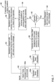
Figure 6 is a flow diagram showing anillustrative method 72 for mapping the cameras (such as the cameras 20) to the directional speakers (such as the directional speakers 22). Theillustrative method 72 includesCamera ID 1 identifying anoperator 74, such as by performing facial recognition on a local video stream provided by theCamera ID 1. Mapping is done in a database during a configuration phase, as indicated atblock 78.Speaker 1 is mapped toCamera ID 1, as indicated atblock 78a.Speaker 2 is mapped toCamera ID 2, as indicated atblock 78b. This continues through each of the speakers and cameras until the Speaker N is mapped to Camera ID N, as indicated atblock 78n. -
Figure 7 is a flow diagram showing anillustrative method 80 for directional voice messaging. Themethod 80 includesinputs 82 such as an alarm voice message to be announced, as indicated atblock 82a, and an operator work schedule, as indicated atblock 82b. Information from theblock 82a is provided to ablock 84, where a determination is made as to which directional speaker will announce the message. From the operator work schedule, information is passed to ablock 86, where a determination is made as to where each operator should be located. Atblock 88, a camera that is assigned to a particular operator location performs facial recognition to see if the particular operator is in position. If so, as determined atdecision block 90, control passes to block 92 and the speaker that is mapped to that camera sends a voice message directed to the location of the particular operator. If not, facial recognition is performed on video streams from the other cameras (e.g.other cameras 20 and/orcameras 26 ofFigure 2 ) in order to locate the particular operator in the control room. Once the operator is located, the speaker or speakers that are mapped to that camera will be aimed at the current location of the particular operator, as indicated atblock 96, and the message is delivered. - Those skilled in the art will recognize that the present disclosure may be manifested in a variety of forms other than the specific embodiments described and contemplated herein. Accordingly, departure in form and detail may be made without departing from the scope and spirit of the present disclosure as described in the appended claims.
Claims (15)
- A video monitoring system comprising:one or more displays arranged to form a video monitoring wall, the video monitoring wall configured to display a plurality of video streams, wherein each of the plurality of video streams is assigned to a particular one of a plurality of operators for monitoring;one or more cameras disposed relative to the video monitoring wall such that each of the one or more cameras has a field of view (FOV) that is directed toward a viewing side of the video monitoring wall, each of the one or more cameras producing a local video stream;one or more directional speakers disposed relative to the video monitoring wall such that each of the one or more directional speakers is directed toward a corresponding location on the viewing side of the video monitoring wall;a controller operably coupled with the one or more displays, the one or more cameras and the one or more directional speakers, the controller configured to:identify that a desired action should be taken by a particular one of the plurality of operators, the desired action is based at least in part on the one or more video streams assigned to the particular one of the plurality of operators;analyze the one or more local video streams to ascertain a current location of the particular one of the plurality of operators in front of the video monitoring wall; anddirect an audio message to the current location of the particular one of the plurality of operators using one or more of the directional speakers.
- The video monitoring system of claim 1, wherein the controller is configured to perform facial recognition on the one or more local video streams in order to ascertain the current location of the particular one of the plurality of operators.
- The video monitoring system of claim 1, wherein the audio message that is directed to the current location of the particular one of the plurality of operators comprises instructions to take the desired action.
- The video monitoring system of claim 1, wherein each of the plurality of video streams that are assigned to the particular one of the plurality of operators are arranged in a first region of the video monitoring wall.
- The video monitoring system of claim 4, wherein upon determine that the desired action should be taken, the controller is configured to display supporting information in the first region of the video monitoring wall.
- The video monitoring system of claim 5, wherein when the desired action is in response to a possible event identified in one or more of the plurality of video streams, the supporting information that is displayed in the first region comprises one or more of the plurality of video streams that capture the possible event.
- The video monitoring system of claim 6, wherein the supporting information includes alphanumeric information that is superimposed over one or more of the video streams being displayed in the first region of the video monitoring wall.
- The video monitoring system of claim 7, wherein the alphanumeric information provides further details regarding the possible event.
- The video monitoring system of claim 1, wherein the audio message directed to the current location of the particular one of the plurality of operators comprises a name of the particular one of the plurality of operators.
- The video monitoring system of claim 1, wherein analyzing the one or more local video streams to ascertain the current location of the particular one of the plurality of operators in front of the video monitoring wall comprises performing facial recognition to positively identify the particular one of the plurality of operators.
- The video monitoring system of claim 1, wherein the FOV of at least some of the one or more cameras are adjustable, and the controller is configured to instruct one or more of the cameras to pan, tilt or zoom, thereby changing its FOV, in order to locate the current location of the particular one of the plurality of operators; and/or
at least some of the one or more cameras are mountable to a moveable base that is configured to translate relative to the video monitoring wall, and the controller is configured to instruct one or more of the cameras to translate relative to the video monitoring wall. - The video monitoring system of claim 1, wherein at least some of the directional speakers are configured to pivot or tilt, and the controller is configured to instruct one or more of the directional speakers to pivot or tilt in order to be more closely aim the one or more direction speakers at the current location of the particular one of the plurality of operators; and/or
at least some of the one or more directional speakers are mountable to a moveable base that is configured to translate relative to the video monitoring wall, and the controller is configured to instruct one or more of the directional speakers to translate relative to the video monitoring wall. - The video monitoring system of claim 1, wherein at least some of the one or more directional speakers are mapped to corresponding ones of the one or more cameras.
- The video monitoring system of claim 1, wherein each of the plurality of video streams is assigned to a particular one of the plurality of operators for monitoring based at least in part on a posted schedule of each of the plurality of operators.
- A method for monitoring a video surveillance system via a video monitoring wall, the method comprising:identifying that a desired action should be taken by a particular one of a plurality of operators tasked with monitoring a plurality of video streams of the video surveillance system;analyzing one or more local video streams captured by one or more cameras that each have a field of view (FOV) that is directed toward a viewing side of the video monitoring wall to ascertain a current location of the particular one of the plurality of operators in front of the video monitoring wall; anddirecting an audio message to the current location of the particular one of the plurality of operators using one or more directional speakers.
Applications Claiming Priority (1)
| Application Number | Priority Date | Filing Date | Title |
|---|---|---|---|
| IN202211059507 | 2022-10-18 |
Publications (2)
| Publication Number | Publication Date |
|---|---|
| EP4358048A1 true EP4358048A1 (en) | 2024-04-24 |
| EP4358048B1 EP4358048B1 (en) | 2026-04-08 |
Family
ID=88197227
Family Applications (1)
| Application Number | Title | Priority Date | Filing Date |
|---|---|---|---|
| EP23199442.7A Active EP4358048B1 (en) | 2022-10-18 | 2023-09-25 | Video monitoring wall with directional acoustic alerts for operators |
Country Status (3)
| Country | Link |
|---|---|
| US (1) | US12361709B2 (en) |
| EP (1) | EP4358048B1 (en) |
| CN (1) | CN117956116A (en) |
Citations (3)
| Publication number | Priority date | Publication date | Assignee | Title |
|---|---|---|---|---|
| WO2007095994A1 (en) * | 2006-02-23 | 2007-08-30 | Robert Bosch Gmbh | Audio module for a video surveillance system, video surveillance system and method for keeping a plurality of locations under surveillance |
| US20160132731A1 (en) * | 2013-06-28 | 2016-05-12 | Nec Corporation | Video surveillance system, video processing apparatus, video processing method, and video processing program |
| WO2016082881A1 (en) * | 2014-11-27 | 2016-06-02 | Abb Technology Ltd | Distribution of audible notifications in a control room |
Family Cites Families (12)
| Publication number | Priority date | Publication date | Assignee | Title |
|---|---|---|---|---|
| US20040133477A1 (en) * | 2001-02-02 | 2004-07-08 | Charles Morris | Self-checkout system with biometric data processing |
| JP3994787B2 (en) * | 2002-04-25 | 2007-10-24 | 株式会社日立製作所 | Surveillance camera system |
| US6873924B1 (en) * | 2003-09-30 | 2005-03-29 | General Electric Company | Method and system for calibrating relative fields of view of multiple cameras |
| US8295597B1 (en) * | 2007-03-14 | 2012-10-23 | Videomining Corporation | Method and system for segmenting people in a physical space based on automatic behavior analysis |
| US8810656B2 (en) * | 2007-03-23 | 2014-08-19 | Speco Technologies | System and method for detecting motion and providing an audible message or response |
| JP2008250908A (en) * | 2007-03-30 | 2008-10-16 | Toshiba Corp | Video discrimination method and video discrimination device |
| US8711201B2 (en) * | 2008-11-04 | 2014-04-29 | Hewlett-Packard Development Company, L.P. | Controlling a video window position relative to a video camera position |
| BRPI1102790A2 (en) * | 2011-06-02 | 2014-03-04 | Cento E Vinte 120 Participacoes E Empreendimentos Ltda | STRUCTURED SPACE FOR PHYSICAL CONDITIONING PRACTICE AND PHYSICAL CONDITION MANAGEMENT METHOD |
| US20150312520A1 (en) | 2014-04-23 | 2015-10-29 | President And Fellows Of Harvard College | Telepresence apparatus and method enabling a case-study approach to lecturing and teaching |
| WO2019090091A1 (en) * | 2017-11-03 | 2019-05-09 | Sensormatic Electronics, LLC | Methods and system for distributed cameras and demographics analysis |
| US10372402B1 (en) | 2018-03-27 | 2019-08-06 | Panoscape Holdings, LLC | Multi-panel, multi-communication video wall and system and method for seamlessly isolating one of more panels for individual user interaction |
| KR102056854B1 (en) | 2019-05-21 | 2019-12-17 | (주)하이퍼월 | Internet protocol video wall system and method of driving the same |
-
2023
- 2023-09-21 CN CN202311224137.0A patent/CN117956116A/en active Pending
- 2023-09-25 EP EP23199442.7A patent/EP4358048B1/en active Active
- 2023-10-12 US US18/485,690 patent/US12361709B2/en active Active
Patent Citations (3)
| Publication number | Priority date | Publication date | Assignee | Title |
|---|---|---|---|---|
| WO2007095994A1 (en) * | 2006-02-23 | 2007-08-30 | Robert Bosch Gmbh | Audio module for a video surveillance system, video surveillance system and method for keeping a plurality of locations under surveillance |
| US20160132731A1 (en) * | 2013-06-28 | 2016-05-12 | Nec Corporation | Video surveillance system, video processing apparatus, video processing method, and video processing program |
| WO2016082881A1 (en) * | 2014-11-27 | 2016-06-02 | Abb Technology Ltd | Distribution of audible notifications in a control room |
Also Published As
| Publication number | Publication date |
|---|---|
| US12361709B2 (en) | 2025-07-15 |
| US20240127591A1 (en) | 2024-04-18 |
| CN117956116A (en) | 2024-04-30 |
| EP4358048B1 (en) | 2026-04-08 |
Similar Documents
| Publication | Publication Date | Title |
|---|---|---|
| US8676493B2 (en) | Systems and methods for better alarm management | |
| US20050231349A1 (en) | Evacuation systems providing enhanced operational control | |
| US9424579B2 (en) | System for group supervision | |
| US7682028B2 (en) | Image transmission system and image transmission method | |
| JP3961687B2 (en) | Supervisory control device | |
| CN1163652C (en) | Web Break Monitoring System in Paper Machine | |
| DE102015213583A1 (en) | Failure detection system and failure detection procedure | |
| JP2010257244A (en) | Evacuation guiding system, and, evacuation guiding method | |
| US10559108B2 (en) | Superimposition of situation expression onto captured image | |
| JP2010074494A (en) | Conference support device | |
| US20130283330A1 (en) | Architecture and system for group video distribution | |
| JP2006165981A (en) | Wireless communication system | |
| EP4358048B1 (en) | Video monitoring wall with directional acoustic alerts for operators | |
| JP2020184292A (en) | Dispersion-type target tracking system | |
| JP2001195124A (en) | Plant monitoring and control equipment | |
| US20100073285A1 (en) | Display device for displaying a system state | |
| JP2019161353A (en) | Monitoring device, monitoring method, and monitoring processing program | |
| CN107545379A (en) | A kind of safe class monitoring and managing method, device, Billboard and system | |
| GB2507729B (en) | Method and apparatus for quality checking | |
| KR101937091B1 (en) | Fine dust alarm broadcasting system | |
| WO2023210052A1 (en) | Voice analysis device, voice analysis method, and voice analysis program | |
| JP2008152476A (en) | Image monitoring device | |
| CN113705413A (en) | Kitchen monitoring method and device and storage medium | |
| JP2015054193A (en) | Patient monitoring system | |
| JP3392431B2 (en) | Video information display device |
Legal Events
| Date | Code | Title | Description |
|---|---|---|---|
| PUAI | Public reference made under article 153(3) epc to a published international application that has entered the european phase |
Free format text: ORIGINAL CODE: 0009012 |
|
| STAA | Information on the status of an ep patent application or granted ep patent |
Free format text: STATUS: REQUEST FOR EXAMINATION WAS MADE |
|
| 17P | Request for examination filed |
Effective date: 20230925 |
|
| AK | Designated contracting states |
Kind code of ref document: A1 Designated state(s): AL AT BE BG CH CY CZ DE DK EE ES FI FR GB GR HR HU IE IS IT LI LT LU LV MC ME MK MT NL NO PL PT RO RS SE SI SK SM TR |
|
| GRAP | Despatch of communication of intention to grant a patent |
Free format text: ORIGINAL CODE: EPIDOSNIGR1 |
|
| STAA | Information on the status of an ep patent application or granted ep patent |
Free format text: STATUS: GRANT OF PATENT IS INTENDED |
|
| INTG | Intention to grant announced |
Effective date: 20251201 |
|
| GRAS | Grant fee paid |
Free format text: ORIGINAL CODE: EPIDOSNIGR3 |
|
| GRAA | (expected) grant |
Free format text: ORIGINAL CODE: 0009210 |
|
| STAA | Information on the status of an ep patent application or granted ep patent |
Free format text: STATUS: THE PATENT HAS BEEN GRANTED |
|
| AK | Designated contracting states |
Kind code of ref document: B1 Designated state(s): AL AT BE BG CH CY CZ DE DK EE ES FI FR GB GR HR HU IE IS IT LI LT LU LV MC ME MK MT NL NO PL PT RO RS SE SI SK SM TR |
|
| REG | Reference to a national code |
Ref country code: CH Ref legal event code: F10 Free format text: ST27 STATUS EVENT CODE: U-0-0-F10-F00 (AS PROVIDED BY THE NATIONAL OFFICE) Effective date: 20260408 Ref country code: GB Ref legal event code: FG4D |
|
| REG | Reference to a national code |
Ref country code: DE Ref legal event code: R096 Ref document number: 602023014794 Country of ref document: DE |