EP4357968A1 - Contactless smart card in the form of a ring - Google Patents
Contactless smart card in the form of a ring Download PDFInfo
- Publication number
- EP4357968A1 EP4357968A1 EP22825422.3A EP22825422A EP4357968A1 EP 4357968 A1 EP4357968 A1 EP 4357968A1 EP 22825422 A EP22825422 A EP 22825422A EP 4357968 A1 EP4357968 A1 EP 4357968A1
- Authority
- EP
- European Patent Office
- Prior art keywords
- cutout
- ring
- microchip
- height
- smart card
- Prior art date
- Legal status (The legal status is an assumption and is not a legal conclusion. Google has not performed a legal analysis and makes no representation as to the accuracy of the status listed.)
- Withdrawn
Links
Images
Classifications
-
- G—PHYSICS
- G06—COMPUTING OR CALCULATING; COUNTING
- G06Q—INFORMATION AND COMMUNICATION TECHNOLOGY [ICT] SPECIALLY ADAPTED FOR ADMINISTRATIVE, COMMERCIAL, FINANCIAL, MANAGERIAL OR SUPERVISORY PURPOSES; SYSTEMS OR METHODS SPECIALLY ADAPTED FOR ADMINISTRATIVE, COMMERCIAL, FINANCIAL, MANAGERIAL OR SUPERVISORY PURPOSES, NOT OTHERWISE PROVIDED FOR
- G06Q20/00—Payment architectures, schemes or protocols
- G06Q20/30—Payment architectures, schemes or protocols characterised by the use of specific devices or networks
- G06Q20/34—Payment architectures, schemes or protocols characterised by the use of specific devices or networks using cards, e.g. integrated circuit [IC] cards or magnetic cards
- G06Q20/352—Contactless payments by cards
-
- G—PHYSICS
- G06—COMPUTING OR CALCULATING; COUNTING
- G06K—GRAPHICAL DATA READING; PRESENTATION OF DATA; RECORD CARRIERS; HANDLING RECORD CARRIERS
- G06K19/00—Record carriers for use with machines and with at least a part designed to carry digital markings
- G06K19/04—Record carriers for use with machines and with at least a part designed to carry digital markings characterised by the shape
-
- A—HUMAN NECESSITIES
- A44—HABERDASHERY; JEWELLERY
- A44C—PERSONAL ADORNMENTS, e.g. JEWELLERY; COINS
- A44C9/00—Finger-rings
- A44C9/0053—Finger-rings having special functions
-
- G—PHYSICS
- G06—COMPUTING OR CALCULATING; COUNTING
- G06K—GRAPHICAL DATA READING; PRESENTATION OF DATA; RECORD CARRIERS; HANDLING RECORD CARRIERS
- G06K19/00—Record carriers for use with machines and with at least a part designed to carry digital markings
- G06K19/06—Record carriers for use with machines and with at least a part designed to carry digital markings characterised by the kind of the digital marking, e.g. shape, nature, code
- G06K19/067—Record carriers with conductive marks, printed circuits or semiconductor circuit elements, e.g. credit or identity cards also with resonating or responding marks without active components
- G06K19/07—Record carriers with conductive marks, printed circuits or semiconductor circuit elements, e.g. credit or identity cards also with resonating or responding marks without active components with integrated circuit chips
- G06K19/0723—Record carriers with conductive marks, printed circuits or semiconductor circuit elements, e.g. credit or identity cards also with resonating or responding marks without active components with integrated circuit chips the record carrier comprising an arrangement for non-contact communication, e.g. wireless communication circuits on transponder cards, non-contact smart cards or RFIDs
-
- G—PHYSICS
- G06—COMPUTING OR CALCULATING; COUNTING
- G06K—GRAPHICAL DATA READING; PRESENTATION OF DATA; RECORD CARRIERS; HANDLING RECORD CARRIERS
- G06K19/00—Record carriers for use with machines and with at least a part designed to carry digital markings
- G06K19/06—Record carriers for use with machines and with at least a part designed to carry digital markings characterised by the kind of the digital marking, e.g. shape, nature, code
- G06K19/067—Record carriers with conductive marks, printed circuits or semiconductor circuit elements, e.g. credit or identity cards also with resonating or responding marks without active components
- G06K19/07—Record carriers with conductive marks, printed circuits or semiconductor circuit elements, e.g. credit or identity cards also with resonating or responding marks without active components with integrated circuit chips
- G06K19/077—Constructional details, e.g. mounting of circuits in the carrier
- G06K19/07749—Constructional details, e.g. mounting of circuits in the carrier the record carrier being capable of non-contact communication, e.g. constructional details of the antenna of a non-contact smart card
-
- G—PHYSICS
- G06—COMPUTING OR CALCULATING; COUNTING
- G06K—GRAPHICAL DATA READING; PRESENTATION OF DATA; RECORD CARRIERS; HANDLING RECORD CARRIERS
- G06K19/00—Record carriers for use with machines and with at least a part designed to carry digital markings
- G06K19/06—Record carriers for use with machines and with at least a part designed to carry digital markings characterised by the kind of the digital marking, e.g. shape, nature, code
- G06K19/067—Record carriers with conductive marks, printed circuits or semiconductor circuit elements, e.g. credit or identity cards also with resonating or responding marks without active components
- G06K19/07—Record carriers with conductive marks, printed circuits or semiconductor circuit elements, e.g. credit or identity cards also with resonating or responding marks without active components with integrated circuit chips
- G06K19/077—Constructional details, e.g. mounting of circuits in the carrier
- G06K19/07749—Constructional details, e.g. mounting of circuits in the carrier the record carrier being capable of non-contact communication, e.g. constructional details of the antenna of a non-contact smart card
- G06K19/07758—Constructional details, e.g. mounting of circuits in the carrier the record carrier being capable of non-contact communication, e.g. constructional details of the antenna of a non-contact smart card arrangements for adhering the record carrier to further objects or living beings, functioning as an identification tag
- G06K19/07762—Constructional details, e.g. mounting of circuits in the carrier the record carrier being capable of non-contact communication, e.g. constructional details of the antenna of a non-contact smart card arrangements for adhering the record carrier to further objects or living beings, functioning as an identification tag the adhering arrangement making the record carrier wearable, e.g. having the form of a ring, watch, glove or bracelet
-
- G—PHYSICS
- G06—COMPUTING OR CALCULATING; COUNTING
- G06K—GRAPHICAL DATA READING; PRESENTATION OF DATA; RECORD CARRIERS; HANDLING RECORD CARRIERS
- G06K19/00—Record carriers for use with machines and with at least a part designed to carry digital markings
- G06K19/06—Record carriers for use with machines and with at least a part designed to carry digital markings characterised by the kind of the digital marking, e.g. shape, nature, code
- G06K19/067—Record carriers with conductive marks, printed circuits or semiconductor circuit elements, e.g. credit or identity cards also with resonating or responding marks without active components
- G06K19/07—Record carriers with conductive marks, printed circuits or semiconductor circuit elements, e.g. credit or identity cards also with resonating or responding marks without active components with integrated circuit chips
- G06K19/077—Constructional details, e.g. mounting of circuits in the carrier
- G06K19/07749—Constructional details, e.g. mounting of circuits in the carrier the record carrier being capable of non-contact communication, e.g. constructional details of the antenna of a non-contact smart card
- G06K19/07773—Antenna details
-
- G—PHYSICS
- G07—CHECKING-DEVICES
- G07F—COIN-FREED OR LIKE APPARATUS
- G07F7/00—Mechanisms actuated by objects other than coins to free or to actuate vending, hiring, coin or paper currency dispensing or refunding apparatus
- G07F7/08—Mechanisms actuated by objects other than coins to free or to actuate vending, hiring, coin or paper currency dispensing or refunding apparatus by coded identity card or credit card or other personal identification means
- G07F7/0806—Details of the card
-
- G—PHYSICS
- G07—CHECKING-DEVICES
- G07F—COIN-FREED OR LIKE APPARATUS
- G07F7/00—Mechanisms actuated by objects other than coins to free or to actuate vending, hiring, coin or paper currency dispensing or refunding apparatus
- G07F7/08—Mechanisms actuated by objects other than coins to free or to actuate vending, hiring, coin or paper currency dispensing or refunding apparatus by coded identity card or credit card or other personal identification means
- G07F7/10—Mechanisms actuated by objects other than coins to free or to actuate vending, hiring, coin or paper currency dispensing or refunding apparatus by coded identity card or credit card or other personal identification means together with a coded signal, e.g. in the form of personal identification information, like personal identification number [PIN] or biometric data
-
- G—PHYSICS
- G06—COMPUTING OR CALCULATING; COUNTING
- G06K—GRAPHICAL DATA READING; PRESENTATION OF DATA; RECORD CARRIERS; HANDLING RECORD CARRIERS
- G06K19/00—Record carriers for use with machines and with at least a part designed to carry digital markings
- G06K19/06—Record carriers for use with machines and with at least a part designed to carry digital markings characterised by the kind of the digital marking, e.g. shape, nature, code
- G06K19/067—Record carriers with conductive marks, printed circuits or semiconductor circuit elements, e.g. credit or identity cards also with resonating or responding marks without active components
- G06K19/07—Record carriers with conductive marks, printed circuits or semiconductor circuit elements, e.g. credit or identity cards also with resonating or responding marks without active components with integrated circuit chips
- G06K19/077—Constructional details, e.g. mounting of circuits in the carrier
- G06K19/07749—Constructional details, e.g. mounting of circuits in the carrier the record carrier being capable of non-contact communication, e.g. constructional details of the antenna of a non-contact smart card
- G06K19/07773—Antenna details
- G06K19/07786—Antenna details the antenna being of the HF type, such as a dipole
-
- G—PHYSICS
- G06—COMPUTING OR CALCULATING; COUNTING
- G06Q—INFORMATION AND COMMUNICATION TECHNOLOGY [ICT] SPECIALLY ADAPTED FOR ADMINISTRATIVE, COMMERCIAL, FINANCIAL, MANAGERIAL OR SUPERVISORY PURPOSES; SYSTEMS OR METHODS SPECIALLY ADAPTED FOR ADMINISTRATIVE, COMMERCIAL, FINANCIAL, MANAGERIAL OR SUPERVISORY PURPOSES, NOT OTHERWISE PROVIDED FOR
- G06Q20/00—Payment architectures, schemes or protocols
- G06Q20/30—Payment architectures, schemes or protocols characterised by the use of specific devices or networks
- G06Q20/32—Payment architectures, schemes or protocols characterised by the use of specific devices or networks using wireless devices
- G06Q20/327—Short range or proximity payments by means of M-devices
- G06Q20/3278—RFID or NFC payments by means of M-devices
Definitions
- the invention relates to ring-shaped smart cards operated using Near Field Communication (NFC) wireless data transmission technology. These smart cards can be used for contactless payments, as tickets for public transport or mass events, for authentication, data exchange, etc.
- NFC Near Field Communication
- Contactless smart cards allow the bank account holder to conduct transactions by exchanging information between a contactless payment device and a reader via a radio-frequency channel.
- the resonance circuit of smart cards usually includes an antenna, a condenser and a microchip connected between each other.
- the state of art provides a contactless ring-shaped smart card ( CN 203930905 U , 05.11.2014) comprising an arc-shaped printed circuit that accommodates a frame antenna and an NFC-microchip connected thereto as well as a combined body comprising the following elements: primary element with a cutout for inserting a printed circuit on the surface oriented in the opposite direction from the user finger, a screening layer closing the cutout, and an external protective layer.
- Drawbacks of this solution include a complex and unreliable design.
- Several body elements make it massive and unstable to loading since the exterior is often subject to mechanical effects including impacts, which may result in lamination of body parts, damages of the printed circuit and failure of the payment device.
- a contactless ring-shaped smart card ( WO 2018020055 A1 , 01.02.2018) is selected as a prototype, comprising an integral body and an interconnected frame antenna, a condenser for more accurate configuration and a microchip on the current-conducing pad supporting NFC technology.
- An integral body on the internal side intended for finger touching provides a cutout shaped as a truncated cone and intended to accommodate the antenna, condenser and microchip.
- the cutout cone is directed inwards the body and has the bottom height of 8 mm, with the ring total length of 9 mm, so there is 0.5 mm on the internal side of the ring allocated for body protrusions on each side of the cutout, which is then sealed along the entire height.
- Such smart card ensures a higher protection of circuit components, but thin edges of body protrusions on the inner side up to the cutout make it insufficiently strong. Ring drawbacks are massiveness since the body is rather wide because of the cutout; and complexity of production since the cone shape of the cutout requires a special approach in manufacturing and installation of a condenser that is necessary for a more accurate configuration of the smart-card operation.
- the invention is intended to create a contactless ring-shaped smart card comprising a cutout on the inner side oriented towards the user finger and having the least number of elements, lower massiveness, simplified design, increased operational and production reliability while keeping all advantages achieved by the prototype.
- the technical result lies in decreased weight and dimensions of the ring with an integral body and a cutout on the inner side while keeping the performance of the smart-card resonance circuit and protecting its components from external mechanical effects.
- a ring-shaped smart card comprising an interconnected frame antenna with a microchip on the current-conducting pad supporting NFC technology and an integral body that has a cutout on the side intended for finger touching, the said cutout comprises an antenna with a microchip and is sealed along its height and is rectangular with the height of no more than 5.0 mm and depth of no more than 1.5 mm, while the height of body protrusions above the cutout is 1.0 to 1.5 mm.
- the microchip has electrical capacity of at least 78 pF.
- the rectangular cutout with the height above 5.0 mm and depth below 1.5 mm, with the total body height below 8 mm, helps reducing the ring weight and dimensions while keeping and even improving the protection of resonance circuit elements (microchip with frame antenna) against external mechanical effects.
- the protection is affected by not only thicker protrusions of the body above the cutout, but also a reduced number of parts that may fail, by means of excluding the condenser and using the microchip with electrical capacity that ensures the smart card performance.
- the rectangular cutout also ensures simplified design since such cutout is made faster, with lower defect probability and is sealed easier that the cone-shaped cutout, and it ensures correct positioning of the microchip with the antenna.
- a contactless ring-shaped smart card can be used for contactless payments, when using public transport or visiting mass events, authentication, data exchange, etc.
- the device contains interconnected solid-state microchip 1 on the current-conducting pad 2 and frame antenna 3 whose contacts are connected with the contacts of microchip 1 as well as integral body 4.
- Microchip 1 supports NFC technology and has electrical capacity ensuring the smart card performance, being at least 78 pF. This capacity is obtained when testing microchips with different capacities. Smart-card performance means performance of its resonance circuit, namely, capability of stable interaction with the reader.
- Body 4 is equipped with rectangular cutout 5 on the inner side intended for finger touching and comprising microchip 1 with frame antenna 3 that has length L from 310 to 490 mm and fits such number of turns that ensures stable resonance frequency of the oscillatory circuit.
- Cutout 5 represents a furrow or a recession made along the entire circumference of the internal ring side ( Figs. 1, 3 ) and height H not more than 5.0 mm and usually not less than 2.0 mm, and depth D usually from 1.2 to 1.5 mm. Cutout 5 is sealed along its height flush with the body protrusions so that the inner side of the ring is smooth.
- the sealant represents a coating made of ceramics, plastic, bi-component epoxy pigmented compounds (epoxy resins) or composites based on ceramic matrix.
- Body 4 can be made of ceramics, plastics, epoxy resins or composite materials.
- the body can have a hole for LED 7 to indicate smart card getting within the reader coverage, which can be represented by a smartphone with NFC technology, a payment terminal, a turn gate or a lock with contactless activation or other devices.
- the contactless ring-shaped smart card operates as follows.
- size S of ring body 4 is 15 to 25 mm
- height H of rectangular cutout 5 is 2.0 to 5.0 mm
- depth D is 1.2 to 1.5 mm
- the said ring body made for the selected NFC microchip on the current-conducting pad 2 with the capacity of 78 pF and body protrusions thickness above the cutout of 1.0 to 1.5 mm.
- the height of antenna 3 is 310 to 490 mm, the said height fits a certain number of turns to ensure stable frequency of the resonance circuit, and the antenna is connected to contacts of microchip 1.
- the connected components ( Fig. 1 ) are placed into the rectangular cutout 5 ( Figs. 2-3 ) that is sealed flush with the inner side surface of body 4. Since there is no need to install the condenser and make a cutout of complex shape, the production becomes faster and less expensive.
- microchip 1 is recorded with personal payment details of the users and the emitting bank payment application that interacts with the seller's acquirer bank via the payment system during the payment transaction. Data is encrypted by authentication keys and protected against re-writing or modification.
- the finished ring with encrypted data is put on user's finger so that the inner smooth side of the ring comprised of protrusions 6 and sealant of cutout 5 abut the finger.
- the resonance circuit formed by frame antenna 3 together with microchip 1 having capacity characteristics ensures transmission of encrypted information via a radio-frequency channel to at least 2 cm.
- circuit components are not damaged and remain operable thanks to fewer parts and thicker body walls with reduced overall dimensions.
- Using a special capsule filler to seal the inner side of the ring may ensure water-rightness, which makes hydrotherapeutic procedure possible without smart card losing its operability.
- the thickness of body protrusions above the cutout is 1.0 mm.
- the thickness of body protrusions above the cutout is 1.0 mm.
- the cutout is sealed with a bi-component epoxy compound.
Landscapes
- Engineering & Computer Science (AREA)
- Physics & Mathematics (AREA)
- General Physics & Mathematics (AREA)
- Theoretical Computer Science (AREA)
- Microelectronics & Electronic Packaging (AREA)
- Computer Hardware Design (AREA)
- Computer Networks & Wireless Communication (AREA)
- Business, Economics & Management (AREA)
- Accounting & Taxation (AREA)
- Strategic Management (AREA)
- General Business, Economics & Management (AREA)
- Details Of Aerials (AREA)
- Credit Cards Or The Like (AREA)
- Adornments (AREA)
- Near-Field Transmission Systems (AREA)
Abstract
Description
- The invention relates to ring-shaped smart cards operated using Near Field Communication (NFC) wireless data transmission technology. These smart cards can be used for contactless payments, as tickets for public transport or mass events, for authentication, data exchange, etc.
- Contactless smart cards allow the bank account holder to conduct transactions by exchanging information between a contactless payment device and a reader via a radio-frequency channel. The resonance circuit of smart cards usually includes an antenna, a condenser and a microchip connected between each other.
- The state of art provides a contactless ring-shaped smart card (
CN 203930905 U , 05.11.2014) comprising an arc-shaped printed circuit that accommodates a frame antenna and an NFC-microchip connected thereto as well as a combined body comprising the following elements: primary element with a cutout for inserting a printed circuit on the surface oriented in the opposite direction from the user finger, a screening layer closing the cutout, and an external protective layer. Drawbacks of this solution include a complex and unreliable design. Several body elements make it massive and unstable to loading since the exterior is often subject to mechanical effects including impacts, which may result in lamination of body parts, damages of the printed circuit and failure of the payment device. - A contactless ring-shaped smart card (
WO 2018020055 A1 , 01.02.2018) is selected as a prototype, comprising an integral body and an interconnected frame antenna, a condenser for more accurate configuration and a microchip on the current-conducing pad supporting NFC technology. An integral body on the internal side intended for finger touching provides a cutout shaped as a truncated cone and intended to accommodate the antenna, condenser and microchip. The cutout cone is directed inwards the body and has the bottom height of 8 mm, with the ring total length of 9 mm, so there is 0.5 mm on the internal side of the ring allocated for body protrusions on each side of the cutout, which is then sealed along the entire height. Such smart card ensures a higher protection of circuit components, but thin edges of body protrusions on the inner side up to the cutout make it insufficiently strong. Ring drawbacks are massiveness since the body is rather wide because of the cutout; and complexity of production since the cone shape of the cutout requires a special approach in manufacturing and installation of a condenser that is necessary for a more accurate configuration of the smart-card operation. - The invention is intended to create a contactless ring-shaped smart card comprising a cutout on the inner side oriented towards the user finger and having the least number of elements, lower massiveness, simplified design, increased operational and production reliability while keeping all advantages achieved by the prototype.
- The technical result lies in decreased weight and dimensions of the ring with an integral body and a cutout on the inner side while keeping the performance of the smart-card resonance circuit and protecting its components from external mechanical effects.
- This result is achieved by having a ring-shaped smart card comprising an interconnected frame antenna with a microchip on the current-conducting pad supporting NFC technology and an integral body that has a cutout on the side intended for finger touching, the said cutout comprises an antenna with a microchip and is sealed along its height and is rectangular with the height of no more than 5.0 mm and depth of no more than 1.5 mm, while the height of body protrusions above the cutout is 1.0 to 1.5 mm.
- The microchip has electrical capacity of at least 78 pF.
- The rectangular cutout with the height above 5.0 mm and depth below 1.5 mm, with the total body height below 8 mm, helps reducing the ring weight and dimensions while keeping and even improving the protection of resonance circuit elements (microchip with frame antenna) against external mechanical effects. The protection is affected by not only thicker protrusions of the body above the cutout, but also a reduced number of parts that may fail, by means of excluding the condenser and using the microchip with electrical capacity that ensures the smart card performance. The rectangular cutout also ensures simplified design since such cutout is made faster, with lower defect probability and is sealed easier that the cone-shaped cutout, and it ensures correct positioning of the microchip with the antenna.
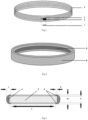
- The invention is explained using
Figs. 1-3 . -
Fig. 1 schematically shows the interconnected microchip and frame antenna. -
Fig. 2 shows the body with the cutout. -
Fig. 3 shows the body in sectional view. - A contactless ring-shaped smart card can be used for contactless payments, when using public transport or visiting mass events, authentication, data exchange, etc.
- The device contains interconnected solid-
state microchip 1 on the current-conductingpad 2 andframe antenna 3 whose contacts are connected with the contacts ofmicrochip 1 as well as integral body 4. - Microchip 1 supports NFC technology and has electrical capacity ensuring the smart card performance, being at least 78 pF. This capacity is obtained when testing microchips with different capacities. Smart-card performance means performance of its resonance circuit, namely, capability of stable interaction with the reader.
- Body 4 is equipped with
rectangular cutout 5 on the inner side intended for finger touching and comprisingmicrochip 1 withframe antenna 3 that has length L from 310 to 490 mm and fits such number of turns that ensures stable resonance frequency of the oscillatory circuit.Cutout 5 represents a furrow or a recession made along the entire circumference of the internal ring side (Figs. 1, 3 ) and height H not more than 5.0 mm and usually not less than 2.0 mm, and depth D usually from 1.2 to 1.5 mm.Cutout 5 is sealed along its height flush with the body protrusions so that the inner side of the ring is smooth. The sealant represents a coating made of ceramics, plastic, bi-component epoxy pigmented compounds (epoxy resins) or composites based on ceramic matrix. - Height W of body 4 is 4.0 to 8.0 mm, total length T is 2.0 mm to 2.8 mm, the thickness of
protrusions 6 above the cutout is 1.0 to 1.5 mm and ring size S is 15 to 25 (Fig. 3 ). Body 4 can be made of ceramics, plastics, epoxy resins or composite materials. - These parameters allow for decreasing the weight and dimensions of the ring while keeping the performance of the smart card resonance circuit and protection of its components against mechanical effects.
- Optionally, the body can have a hole for
LED 7 to indicate smart card getting within the reader coverage, which can be represented by a smartphone with NFC technology, a payment terminal, a turn gate or a lock with contactless activation or other devices. - The contactless ring-shaped smart card operates as follows.
- Based on the existing input data, size S of ring body 4 is 15 to 25 mm, height H of
rectangular cutout 5 is 2.0 to 5.0 mm, depth D is 1.2 to 1.5 mm, the said ring body made for the selected NFC microchip on the current-conductingpad 2 with the capacity of 78 pF and body protrusions thickness above the cutout of 1.0 to 1.5 mm. The height ofantenna 3 is 310 to 490 mm, the said height fits a certain number of turns to ensure stable frequency of the resonance circuit, and the antenna is connected to contacts ofmicrochip 1. The connected components (Fig. 1 ) are placed into the rectangular cutout 5 (Figs. 2-3 ) that is sealed flush with the inner side surface of body 4. Since there is no need to install the condenser and make a cutout of complex shape, the production becomes faster and less expensive. - In case of using the smart card for payment,
microchip 1 is recorded with personal payment details of the users and the emitting bank payment application that interacts with the seller's acquirer bank via the payment system during the payment transaction. Data is encrypted by authentication keys and protected against re-writing or modification. - The finished ring with encrypted data is put on user's finger so that the inner smooth side of the ring comprised of
protrusions 6 and sealant ofcutout 5 abut the finger. When the ring is within the coverage zone of the reader, the resonance circuit formed byframe antenna 3 together withmicrochip 1 having capacity characteristics ensures transmission of encrypted information via a radio-frequency channel to at least 2 cm. - In case of active motions and mechanical effects in the form of possible impacts against body 4 and its
faces including cutouts 6, the circuit components are not damaged and remain operable thanks to fewer parts and thicker body walls with reduced overall dimensions. Using a special capsule filler to seal the inner side of the ring may ensure water-rightness, which makes hydrotherapeutic procedure possible without smart card losing its operability. - Below are embodiments of the invention.
- When using the microchip on the current-conducting pad with the capacity of 78 pF with dimensions 1.9x4.0 mm and the antenna 0.08 mm thick, the body dimensions are chosen as follows: height W= 4.0 mm, thickness T = 2.0 mm, cutout H = 2.0 mm, depth D = 1.2 mm. The thickness of body protrusions above the cutout is 1.0 mm. To obtain a stable frequency of the resonance circuit, for example, for a ring size S = 20 mm, the antenna with length L = 435 mm is fitted into 6 turns.
- When using the microchip on the current-conducting pad with the capacity of 78 pF with dimensions 3.0×4.0 mm and the antenna 0.2 mm thick, the body dimensions are chosen as follows: height W = 6.0 mm, thickness T = 2.5 mm, cutout H = 4.0 mm, depth D = 1.37 mm. The thickness of body protrusions above the cutout is 1.0 mm. To obtain a stable frequency of the resonance circuit, for example, for a ring size S = 20 mm, the antenna with length L = 435 mm is fitted into 6 turns.
- When using the microchip on the current-conducting pad with the capacity of 78 pF with dimensions 3.0×4.0 mm and the antenna 0.3 mm thick, the body dimensions are chosen as follows: height W = 8.0 mm, thickness T = 2.8 mm, cutout H = 5.0 mm, depth D = 1.5 mm. This body thickness is selected to ensure stability against mechanical effects when making a hole for the LED. The thickness of body protrusions above the cutout is 1.5 mm. To obtain a stable frequency of the resonance circuit, for example, for a ring size S = 20 mm, the antenna with length L = 350 mm is fitted into 5 turns.
- In all cases, the cutout is sealed with a bi-component epoxy compound.
- Testing several rings made with the proposed body has confirmed smart card operability and protection of its components against external mechanical effects while reducing weight and dimensions.
- In this manner, the invention achieves the claimed technical result.
Claims (2)
- Ring-shaped smart card comprising an interconnected frame antenna with a microchip on the current-conducting pad supporting NFC technology and an integral body that has a cutout on the side intended for finger touching, the said cutout comprises an antenna with a microchip and is sealed along its height characterized in that the cutout is rectangular with the height of no more than 5.0 mm and depth of no more than 1.5 mm, while the height of body protrusions above the cutout is 1.0 to 1.5 mm.
- Smart card according to claims 1 or 2 characterized in that the microchip has electrical capacity of at least 78 pF.
Applications Claiming Priority (2)
| Application Number | Priority Date | Filing Date | Title |
|---|---|---|---|
| RU2021117422A RU2765607C1 (en) | 2021-06-16 | 2021-06-16 | Contactless smart card in the form of a ring |
| PCT/RU2022/050108 WO2022265535A1 (en) | 2021-06-16 | 2022-03-31 | Contactless smart card in the form of a ring |
Publications (2)
| Publication Number | Publication Date |
|---|---|
| EP4357968A1 true EP4357968A1 (en) | 2024-04-24 |
| EP4357968A4 EP4357968A4 (en) | 2025-06-04 |
Family
ID=80214534
Family Applications (1)
| Application Number | Title | Priority Date | Filing Date |
|---|---|---|---|
| EP22825422.3A Withdrawn EP4357968A4 (en) | 2021-06-16 | 2022-03-31 | Contactless smart card in the form of a ring |
Country Status (7)
| Country | Link |
|---|---|
| EP (1) | EP4357968A4 (en) |
| JP (1) | JP2024524940A (en) |
| DE (1) | DE112022003067T5 (en) |
| GB (1) | GB2623017A (en) |
| RU (1) | RU2765607C1 (en) |
| WO (1) | WO2022265535A1 (en) |
| ZA (1) | ZA202401864B (en) |
Families Citing this family (1)
| Publication number | Priority date | Publication date | Assignee | Title |
|---|---|---|---|---|
| WO2025159657A1 (en) * | 2024-01-26 | 2025-07-31 | Вега Пэй Информэйшэн Текнолоджи Нетворк Сервисес Л.Л.К | Contactless smart card in the form of a metal ring |
Family Cites Families (11)
| Publication number | Priority date | Publication date | Assignee | Title |
|---|---|---|---|---|
| DE102011056329A1 (en) * | 2011-12-13 | 2013-06-13 | Infineon Technologies Ag | Smart card module of smart card e.g. payment card, has chip external coil and chip external capacitor that are arranged to form a module arrangement which produces resonant frequency corresponding to operating frequency |
| CN203930905U (en) | 2014-06-24 | 2014-11-05 | 深圳小木科技有限公司 | A kind of finger ring that energy is provided based on RFID |
| CN204013533U (en) * | 2014-07-18 | 2014-12-10 | 丁绍杰 | A narrow and safe NFC ring device |
| JP6598300B2 (en) * | 2015-10-29 | 2019-10-30 | Necプラットフォームズ株式会社 | Inductive read / write device complex antenna and wearable terminal |
| GB2552654A (en) * | 2016-07-29 | 2018-02-07 | Fifth Dimension Digital Ltd | Near field communication ring |
| DE102017104046A1 (en) * | 2017-02-27 | 2018-08-30 | Infineon Technologies Ag | NEAR FIELD COMMUNICATION-RING |
| JP7236798B2 (en) * | 2017-05-31 | 2023-03-10 | 株式会社 Mtg | RING TYPE WEARABLE TERMINAL AND MANUFACTURING METHOD THEREOF |
| RU183111U1 (en) * | 2018-06-06 | 2018-09-11 | Акционерное общество "Пэй Ринг" | Contactless smart card |
| RU2735275C2 (en) * | 2018-06-06 | 2020-10-29 | Акционерное общество "Пэй Ринг" | Noncontact smart card |
| JP2020018380A (en) * | 2018-07-30 | 2020-02-06 | 株式会社川口電機製作所 | Rings and ring systems |
| US10509994B1 (en) * | 2019-05-08 | 2019-12-17 | Chi Huynh | Ring for use in near field communication (NFC) and method of making same |
-
2021
- 2021-06-16 RU RU2021117422A patent/RU2765607C1/en active
-
2022
- 2022-03-31 DE DE112022003067.4T patent/DE112022003067T5/en active Pending
- 2022-03-31 EP EP22825422.3A patent/EP4357968A4/en not_active Withdrawn
- 2022-03-31 JP JP2023577785A patent/JP2024524940A/en active Pending
- 2022-03-31 WO PCT/RU2022/050108 patent/WO2022265535A1/en not_active Ceased
- 2022-03-31 GB GB2400294.1A patent/GB2623017A/en active Pending
-
2024
- 2024-03-05 ZA ZA2024/01864A patent/ZA202401864B/en unknown
Also Published As
| Publication number | Publication date |
|---|---|
| DE112022003067T5 (en) | 2024-05-29 |
| EP4357968A4 (en) | 2025-06-04 |
| RU2765607C1 (en) | 2022-02-01 |
| WO2022265535A1 (en) | 2022-12-22 |
| JP2024524940A (en) | 2024-07-09 |
| GB2623017A (en) | 2024-04-03 |
| ZA202401864B (en) | 2024-04-24 |
| GB202400294D0 (en) | 2024-02-21 |
Similar Documents
| Publication | Publication Date | Title |
|---|---|---|
| US6837438B1 (en) | Non-contact information medium and communication system utilizing the same | |
| CN102648476B (en) | Amplify radiofrequency signal | |
| EP4049179B1 (en) | Metal card with biometric features | |
| US9304555B2 (en) | Magnetically coupling radio frequency antennas | |
| EP2250631B1 (en) | Methods and apparatus for preserving privacy in an rfid system | |
| EP1279140B1 (en) | Integrated circuit card and case therefor | |
| KR101188791B1 (en) | Card-type information recording medium having embedded antenna for near field communication and manufacturing thereof | |
| AU2008243012B2 (en) | Anti-interrogation for portable device | |
| US20120061466A1 (en) | Switching Between Internal and External Antennas | |
| JP4109029B2 (en) | Mobile device with IC card replacement function | |
| CN101743557A (en) | Shielding for Portable Consumer Devices | |
| JP2009505287A (en) | Non-contact proximity communication apparatus and method | |
| US8556182B2 (en) | Card data storage device with detector plate | |
| WO2012019768A1 (en) | Security system for at least an ic integrated circuit, securely integrated circuit card and method of secure wireless communication | |
| US20210271953A1 (en) | Contactless smart card | |
| GB2623017A (en) | Contactless smart card in the form of a ring | |
| US10586142B2 (en) | Finger-controlled contactless chip card | |
| JP2021524624A (en) | Electronic passport secured for unauthorized reading | |
| RU207076U1 (en) | Ring-shaped contactless smart card | |
| Chirico | Smart card programming | |
| KR100480516B1 (en) | Smart card module mounted in the wire/wireless communication terminal | |
| JP4718192B2 (en) | Reader / Writer | |
| TWI309386B (en) | ||
| KR200327318Y1 (en) | Cellular phone battery equipped with non contcating smart IC chip module | |
| JP4100127B2 (en) | Reader / writer for card IC |
Legal Events
| Date | Code | Title | Description |
|---|---|---|---|
| STAA | Information on the status of an ep patent application or granted ep patent |
Free format text: STATUS: THE INTERNATIONAL PUBLICATION HAS BEEN MADE |
|
| PUAI | Public reference made under article 153(3) epc to a published international application that has entered the european phase |
Free format text: ORIGINAL CODE: 0009012 |
|
| STAA | Information on the status of an ep patent application or granted ep patent |
Free format text: STATUS: REQUEST FOR EXAMINATION WAS MADE |
|
| 17P | Request for examination filed |
Effective date: 20240115 |
|
| AK | Designated contracting states |
Kind code of ref document: A1 Designated state(s): AL AT BE BG CH CY CZ DE DK EE ES FI FR GB GR HR HU IE IS IT LI LT LU LV MC MK MT NL NO PL PT RO RS SE SI SK SM TR |
|
| DAV | Request for validation of the european patent (deleted) | ||
| DAX | Request for extension of the european patent (deleted) | ||
| A4 | Supplementary search report drawn up and despatched |
Effective date: 20250508 |
|
| RIC1 | Information provided on ipc code assigned before grant |
Ipc: G06K 19/04 20060101AFI20250501BHEP |
|
| STAA | Information on the status of an ep patent application or granted ep patent |
Free format text: STATUS: THE APPLICATION IS DEEMED TO BE WITHDRAWN |
|
| 18D | Application deemed to be withdrawn |
Effective date: 20251128 |