EP4357763A1 - Measurement system and measurement method - Google Patents
Measurement system and measurement method Download PDFInfo
- Publication number
- EP4357763A1 EP4357763A1 EP23201193.2A EP23201193A EP4357763A1 EP 4357763 A1 EP4357763 A1 EP 4357763A1 EP 23201193 A EP23201193 A EP 23201193A EP 4357763 A1 EP4357763 A1 EP 4357763A1
- Authority
- EP
- European Patent Office
- Prior art keywords
- region
- measurement
- light source
- test strip
- illuminator
- Prior art date
- Legal status (The legal status is an assumption and is not a legal conclusion. Google has not performed a legal analysis and makes no representation as to the accuracy of the status listed.)
- Pending
Links
Images








Classifications
-
- G—PHYSICS
- G01—MEASURING; TESTING
- G01N—INVESTIGATING OR ANALYSING MATERIALS BY DETERMINING THEIR CHEMICAL OR PHYSICAL PROPERTIES
- G01N21/00—Investigating or analysing materials by the use of optical means, i.e. using sub-millimetre waves, infrared, visible or ultraviolet light
- G01N21/84—Systems specially adapted for particular applications
- G01N21/8483—Investigating reagent band
-
- G—PHYSICS
- G01—MEASURING; TESTING
- G01N—INVESTIGATING OR ANALYSING MATERIALS BY DETERMINING THEIR CHEMICAL OR PHYSICAL PROPERTIES
- G01N21/00—Investigating or analysing materials by the use of optical means, i.e. using sub-millimetre waves, infrared, visible or ultraviolet light
- G01N21/01—Arrangements or apparatus for facilitating the optical investigation
-
- G—PHYSICS
- G01—MEASURING; TESTING
- G01N—INVESTIGATING OR ANALYSING MATERIALS BY DETERMINING THEIR CHEMICAL OR PHYSICAL PROPERTIES
- G01N21/00—Investigating or analysing materials by the use of optical means, i.e. using sub-millimetre waves, infrared, visible or ultraviolet light
- G01N21/75—Systems in which material is subjected to a chemical reaction, the progress or the result of the reaction being investigated
- G01N21/77—Systems in which material is subjected to a chemical reaction, the progress or the result of the reaction being investigated by observing the effect on a chemical indicator
- G01N21/78—Systems in which material is subjected to a chemical reaction, the progress or the result of the reaction being investigated by observing the effect on a chemical indicator producing a change of colour
-
- G—PHYSICS
- G06—COMPUTING OR CALCULATING; COUNTING
- G06K—GRAPHICAL DATA READING; PRESENTATION OF DATA; RECORD CARRIERS; HANDLING RECORD CARRIERS
- G06K7/00—Methods or arrangements for sensing record carriers, e.g. for reading patterns
- G06K7/10—Methods or arrangements for sensing record carriers, e.g. for reading patterns by electromagnetic radiation, e.g. optical sensing; by corpuscular radiation
- G06K7/10544—Methods or arrangements for sensing record carriers, e.g. for reading patterns by electromagnetic radiation, e.g. optical sensing; by corpuscular radiation by scanning of the records by radiation in the optical part of the electromagnetic spectrum
- G06K7/10821—Methods or arrangements for sensing record carriers, e.g. for reading patterns by electromagnetic radiation, e.g. optical sensing; by corpuscular radiation by scanning of the records by radiation in the optical part of the electromagnetic spectrum further details of bar or optical code scanning devices
- G06K7/10861—Methods or arrangements for sensing record carriers, e.g. for reading patterns by electromagnetic radiation, e.g. optical sensing; by corpuscular radiation by scanning of the records by radiation in the optical part of the electromagnetic spectrum further details of bar or optical code scanning devices sensing of data fields affixed to objects or articles, e.g. coded labels
-
- H—ELECTRICITY
- H04—ELECTRIC COMMUNICATION TECHNIQUE
- H04N—PICTORIAL COMMUNICATION, e.g. TELEVISION
- H04N23/00—Cameras or camera modules comprising electronic image sensors; Control thereof
- H04N23/70—Circuitry for compensating brightness variation in the scene
- H04N23/74—Circuitry for compensating brightness variation in the scene by influencing the scene brightness using illuminating means
-
- G—PHYSICS
- G01—MEASURING; TESTING
- G01N—INVESTIGATING OR ANALYSING MATERIALS BY DETERMINING THEIR CHEMICAL OR PHYSICAL PROPERTIES
- G01N2201/00—Features of devices classified in G01N21/00
- G01N2201/02—Mechanical
- G01N2201/022—Casings
- G01N2201/0221—Portable; cableless; compact; hand-held
-
- G—PHYSICS
- G01—MEASURING; TESTING
- G01N—INVESTIGATING OR ANALYSING MATERIALS BY DETERMINING THEIR CHEMICAL OR PHYSICAL PROPERTIES
- G01N2201/00—Features of devices classified in G01N21/00
- G01N2201/06—Illumination; Optics
- G01N2201/061—Sources
-
- G—PHYSICS
- G01—MEASURING; TESTING
- G01N—INVESTIGATING OR ANALYSING MATERIALS BY DETERMINING THEIR CHEMICAL OR PHYSICAL PROPERTIES
- G01N2201/00—Features of devices classified in G01N21/00
- G01N2201/06—Illumination; Optics
- G01N2201/069—Supply of sources
- G01N2201/0692—Regulated sources; stabilised supply
Definitions
- the present invention relates to a measurement system and a measurement method for optically detecting a measurement object in a sample by spreading the measurement object with a test strip.
- a measurement system for optically detecting a measurement object in a specimen by spreading the measurement object with a test strip for example, techniques as shown in WO 2020/003021 A1 and JP 2015-070572 A are disclosed.
- a test strip is illuminated with a multicolor LED, and the color intensity of the test strip is analyzed from an image obtained by simultaneously capturing the test strip and a calibration pad with a camera.
- an image reading device that blocks ambient light is provided with a light source controller for controlling plural light sources in order to control plural lighting patterns.
- the technique described in WO 2020/003021 A1 aims to capture plural images with different combinations of light sources of multicolor LEDs and obtain an optimum image from among them. Furthermore, the technique described in JP 2015-070572 A aims to obtain high-quality image data by including plural light sources, capturing different images according to the light sources, and then combining the different images. That is, in the techniques described in these prior art documents, different images by plural light sources are exclusively used for imaging one imaging region of a test strip.
- An embodiment of the present disclosure provides a measurement system and a measurement method capable of, in a case in which there are plural imaging regions in a test strip, performing appropriate imaging according to the imaging regions.
- An aspect of the present disclosure is a measurement system including: an insertion gate into which a test strip including a first region and a second region is to be inserted; a holder that accommodates the test strip inserted via the insertion gate; a housing including a window facing the test strip accommodated in the holder; and a smart device including an illuminator that illuminates the second region of the test strip accommodated in the holder and including a camera that images the first region and the second region.
- the housing includes a mounting part that places the smart device on an outer surface of the housing, in a state in which the camera and the illuminator are disposed at positions facing the window, and a measurement light source provided at a position to irradiate the first region of the test strip accommodated in the holder. Furthermore, in a case in which the camera images the first region, the illuminator is turned off while the measurement light source is turned on, and in a case in which the camera images the second region, the illuminator is turned on.
- a measurement system and a measurement method capable of, in a case in which there are plural imaging regions in a test strip, performing appropriate imaging according to the imaging regions.
- Fig. 1 is an upper perspective view illustrating a holding unit 40 used in a measurement system 10 (see Fig. 11 ) of the present embodiment.
- the holding unit 40 as illustrated in Fig. 1 may be included as a member constituting a housing 20 (see Fig. 8 ).
- the holding unit 40 has a box shape, and two openings of a measurement opening 43 and an identification opening 44 are formed on an upper surface.
- An optical filter 45 is fitted into the measurement opening 43.
- the upper surface is further provided with a sensor 47 that senses light.
- An insertion gate 41 into which a test strip 60 (see Fig. 3 ) described later is inserted is opened in a side surface of the holding unit 40.
- An internal space of the insertion gate 41 is a holder 46 that is a space in which a part of the test strip 60 is accommodated, communicating with the measurement opening 43 and the identification opening 44.
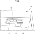
- Fig. 2 is an enlarged lower perspective view of the vicinity of the insertion gate 41 of the holding unit 40.
- the sensor 47 is provided in the vicinity of the measurement opening 43 in the holder 46 that is the internal space of the insertion gate 41.
- a measurement light source 42 (see Fig. 13 ) provided inside the holder 46 emits light including a light beam having a wavelength suitable for imaging a first region 61.
- the optical filter 45 has an optical characteristic of suitably transmitting only a light beam having a wavelength suitable for the imaging.
- Fig. 3 illustrates the test strip 60 used in the measurement system 10 (see Fig. 11 ) of the present embodiment in plan view.
- the test strip 60 has a flat rod-like outer shape.
- a grip portion 65 whose upper surface side is recessed is formed at one end of the test strip 60, and the test strip 60 can be gripped with fingers by holding the grip portion 65.
- a test paper 64 having an elongated shape along a longitudinal direction of the test strip 60 is accommodated in the test strip 60. The test paper 64 is exposed upward at two openings formed on an upper surface of the test strip 60.
- a portion closer to the grip portion 65 is a sample spotting portion 63, and a portion farther from the grip portion 65 is the first region 61 that is a measurement region where the measurement of a measurement object is performed.
- a second region 62 as an identification region in which information regarding the test strip 60 is recorded is formed on the other end side of the test strip 60, that is, on the upper surface of a place farthest from the grip portion 65.
- a side close to the grip portion 65 is referred to as an "upstream side”
- a side close to the second region 62 is referred to as a "downstream side".
- the test paper 64 is obtained by applying a water absorbing layer to a surface of a water absorbent such as filter paper or a synthetic resin substrate.
- the test paper 64 contains a reagent that reacts with a measurement object to develop color.
- a sample assumed to contain a measurement object is spotted to the sample spotting portion 63.
- the sample include a liquid specimen collected from a living body, for example, blood or urine, or a diluent obtained by diluting these with an appropriate solvent, or a solid or mucus collected from a living body, or a liquid specimen obtained by diluting or suspending these in an appropriate solvent.
- the measurement object include a component contained in the liquid specimen, or an antigen derived from an exogenous microorganism or virus.
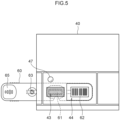
- Fig. 4 is an upper perspective view illustrating a state in which the test strip 60 is attached to the holding unit 40. Furthermore, Fig. 5 illustrates this state in plan view. As illustrated in Fig. 4 and Fig. 5 , the test strip 60 is inserted into the holder 46 via the insertion gate 41 with the downstream side first. In this state, as illustrated in Fig. 5 , the first region 61 is at the same plane position as the measurement opening 43, and the second region 62 is at the same plane position as the identification opening 44.
- the liquid specimen flows in the test paper 64 to the downstream side by capillary phenomenon, and a control reaction zone indicating the spotting of the liquid specimen is generated in the first region 61.
- a target reaction zone having a strength corresponding to a concentration of the measurement object is generated.
- the measurement system 10 of the present embodiment measures the concentration of the measurement object by irradiating the target reaction zone with light emitted from the measurement light source 42 and measuring the intensity of the generated light.
- identification information which is information regarding the test strip 60, such as what type of the test sheet 64 is accommodated in the test strip 60.
- identification information include a barcode, a QR code (registered trademark), and the like.
- Fig. 6 is an upper perspective view illustrating a mounting part 30 used in the measurement system 10 (see Fig. 11 ) of the present embodiment. Furthermore, Fig. 7 illustrates the mounting part 30 in bottom view.
- the mounting part 30 is configured as a paper box having a substantially rectangular parallelepiped shape with an upper surface and a lower surface opened. Four side surfaces of the mounting part 30 form an outer wall portion 34 erected vertically.
- a placement frame 32 which is a frame on which a smart device 50 (see Fig. 10 ) to be described later is placed, is formed on the upper surface of the mounting part 30.
- a box-shaped light shielding portion 33 is formed in which the upper surface is closed while the window 31 is opened, and the lower surface is opened (see Fig. 7 ).
- a surface on a side where the light shielding portion 33 is located is referred to as a front surface 34a
- a surface on an opposite side thereof is referred to as a back surface 34b
- a surface on a left side when viewed from the front surface 34a is referred to as a left side surface 34c
- a surface on an opposite side thereof is referred to as a right side surface 34d.
- the inside of the mounting part 30 is partitioned by a reinforcing portion 35 parallel to the front surface 34a and the back surface 34b.
- a rectangular cutout portion 36 is formed at a front side lower edge of the left side surface 34c.
- a gap is formed between a lower edge of the light shielding portion 33 and a lower edge of the outer wall portion 34, and a space surrounded by the front surface 34a, the reinforcing portion 35, the left side surface 34c, and the right side surface 34d in four directions with this gap as a height is referred to as an accommodation region 37.
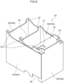
- the housing 20 illustrated in Fig. 8 is configured. In this state, the cutout portion 36 of the mounting part 30 and the insertion gate 41 of the holding unit 40 coincide with each other.
- a state in which the test strip 60 is attached to the insertion gate 41 in this state as illustrated in Fig. 4 and Fig. 5 is as illustrated in the upper perspective view illustrated in Fig. 9 .
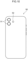
- Fig. 10 illustrates the smart device 50 used in the measurement system 10 (see Fig. 11 ) of the present embodiment in a state of being placed on the housing 20 in a bottom view.
- a smartphone is used as the smart device 50.
- a tablet terminal with a camera function may be used as the smart device 50.
- On the bottom surface side (so-called back surface) of the smart device 50 a camera 51 configured as a camera and an illuminator 52 configured as a flash that emits visible light beside the camera are provided.
- a top surface side (so-called surface) of the smart device 50 is a display unit 53.
- the smart device 50 illustrated in Fig. 10 is placed inside the placement frame 32 of the housing 20 illustrated in Fig. 9 with the camera 51 and the illuminator 52 aligned with the window 31 and the display unit 53 facing upward, whereby the measurement system 10 of the present embodiment as illustrated in the upper perspective view of Fig. 11 is configured.
- an upper perspective view of Fig. 12 illustrating a state in which the front surface 34a, the left side surface 34c, and the right side surface 34d of the outer wall portion 34 are removed from this state, the measurement opening 43 and the identification opening 44 of the holding unit 40 are covered with the light shielding portion 33, and entry of light from the outside world is prevented.
- the measurement opening 43 and the optical filter 45 are located above the first region 61 of the test strip 60, and the identification opening 44 is located above the second region 62.
- the measurement light source 42 that irradiates the first region 61 from obliquely above is installed on a slightly back surface side below the identification opening 44.
- the window 31 of the mounting part 30 is positioned directly above the measurement opening 43, and the camera 51 of the smart device 50 covers the second region 62 in addition to the first region 61 through the window.
- Fig. 14 is a functional block diagram illustrating the measurement system 10 of the present embodiment.
- the smart device 50 is provided with the camera 51 and the illuminator 52 illustrated in Fig. 10 , the display unit 53 illustrated in Fig. 11 , and a controller 100 that controls these units.
- the controller 100 functions as the following units by using a CPU 110, a ROM 120, a RAM 130, and a storage device 150 to be described later as hardware resources of a computer.
- the controller 100 functions as an illumination switching unit 200 that switches on/off of illumination by the illuminator 52.
- the illumination switching unit 200 can be realized as an application installed in the smart device 50, but can also be realized as a unit using electric or optical sensing with the holding unit 40 or as a wireless communication unit (for example, Bluetooth (registered trademark) or the like) with the holding unit 40.
- the controller 100 functions as an imaging condition storage unit 210 that stores imaging conditions by the camera 51. Conditions defined as the imaging conditions include, for example, a standby time required for a reaction between the measurement object and the reagent.
- the controller 100 functions as a spotting detection unit 220 that detects spotting of the sample on the test strip 60 through the camera 51.
- the controller 100 functions as a standby time measurement unit 230 that measures the standby time.
- the controller 100 functions as an image storage unit 240 that stores the image of the first region 61 captured by the camera 51.
- the controller 100 includes the central processing unit (CPU) 110, the read only memory (ROM) 120, the random access memory (RAM) 130, and the storage device 150.
- the respective configurations are communicably connected to each other via a bus 190.
- the CPU 110 is a central processing unit, and executes various programs and controls each unit. That is, the CPU 110 reads a program from the ROM 120 or the storage device 150, and executes the program using the RAM 130 as a work area. The CPU 110 controls the measurement system 10 according to a program recorded in the ROM 120 or the storage device 150.
- the ROM 120 stores various programs and various data.
- the RAM 130 temporarily stores programs or data as a work area.
- the storage device 150 is configured as a storage by a hard disk drive (HDD), a solid state drive (SSD), or a flash memory, and stores various programs including an operating system and various data.
- the holding unit 40 includes the measurement light source 42 that irradiates the first region 61, the sensor 47 that detects on/off of the illuminator 52, and a light source controller 48 that turns on the measurement light source 42 when a signal from the sensor 47 is input.
- the light source controller 48 is configured as a hardware resource of a computer. Note that the light source controller 48 can realize that the measurement light source 42 is turned on regardless of an input mode of the signal from the sensor 47 (for example, in a wired or wireless manner,) as long as it can perform control to turn on the measurement light source 42 at the time of imaging the first region 61 to be described later. Furthermore, the light source controller 48 can also perform control to turn off the measurement light source 42.
- the measurement system 10 of the present embodiment includes the insertion gate 41 into which the test strip 60 including the first region 61 and the second region 62 is inserted, the holder 46 that accommodates the test strip 60 inserted via the insertion gate 41, the housing 20 including the window 31 facing the test strip 60 accommodated in the holder 46, and the smart device 50 including the illuminator 52 that illuminates the second region 62 of the test strip 60 accommodated in the holder 46 and including the camera 51 that images the first region 61 and the second region 62.
- the housing 20 includes a mounting part 30 that places the smart device 50 on the outer surface of the housing 20 in a state in which the camera 51 and the illuminator 52 are disposed at positions facing the window 31, the holding unit 40 that holds the test strip 60 inside accommodated in the holder 46, and the measurement light source 42 provided at a position to irradiate the first region 61 inside the holding unit 40. Then, in the measurement system 10, as will be described later, the illuminator 52 is turned off while the measurement light source 42 is turned on when the camera 51 images the first region 61, and the illuminator 52 is turned on when the camera 51 images the second region 62.
- imaging using an appropriate light source can be performed according to the imaging regions.
- the controller 100 functioning as the illumination switching unit 200 that switches on/off of the illumination by the illuminator 52 can perform control to turn on the illuminator 52 at the time of imaging the second region 62 and to turn off the illuminator 52 at the time of imaging the first region 61.
- the light source controller 48 can perform control to turn on the measurement light source 42 at the time of imaging the first region 61.
- the light source controller 48 preferably performs control to turn off the measurement light source 42 at the time of imaging the second region 62.
- the first region 61 is a measurement region for measuring a measurement object in the test strip 60
- the second region 62 is an identification region in which identification information of the test strip 60 is recorded.
- the measurement object in the sample is detected by color development by a reagent that specifically reacts with the measurement object in the target reaction zone, capture of the measurement object by a reagent that specifically binds to the measurement object, or the like.
- the identification region include a region to which a barcode, a QR code (registered trademark), or the like is attached.
- Examples of the identification information recorded in the identification region include the type of the test paper 64 contained in the test strip 60, measurement conditions suitable for the test strip 60, lot information of the test strip 60, and the like.
- the measurement light source 42 is a light source suitable for detecting a measurement object in the first region 61 as a measurement region.
- the measurement light source 42 can perform appropriate imaging by using ultraviolet light. Note that, as a result, the measurement light source 42 having a wavelength corresponding to the measurement object can be used to image the first region 61 as the measurement region, and the illuminator 52 of the smart device 50 can be used as the light source to image the second region 62 as the identification region.
- the first region 61 is not limited to the measurement region, and may be an identification region as long as imaging can be appropriately performed under the lighting of the measurement light source 42, or may be a correction region for measuring a light amount of the measurement light source 42 or the illuminator 52 or the deterioration of the test paper 64 and correcting the measurement of the measurement object, or may be other regions.
- the second region 62 is not limited to the identification information, and may be a measurement area, a correction area, or other areas as long as imaging can be appropriately performed under the lighting of the illuminator 52. Since the illuminator 52 is generally a flash of the smart device 50 that emits visible light, the second region 62 is preferably a region including a measurement object that can be measured with visible light.
- the measurement light source 42 can be turned on only when it is necessary to image the first region 61, the exhaustion of the measurement light source 42 can be prevented.
- the measurement system 10 on which the smart device 50 is placed is prepared in the housing 20 in which the holding unit 40 is attached to the mounting part 30, and the test strip 60 is inserted via the insertion gate 41.
- the application for measurement installed in the smart device 50 is activated, and measurement is started.
- the illumination switching unit 200 turns on the illuminator 52.
- the measurement light source 42 of the holding unit 40 is turned off.
- the camera 51 captures an image of the second region 62, which is the identification region, using the illuminator 52 as a light source.
- the operation proceeds to a stage illustrated in S120.
- the controller 100 refers to the imaging condition storage unit 210 (see Fig. 14 ) from the captured image of the second region 62 to acquire the imaging conditions at the time of measurement by the test strip 60.
- an appropriate amount of sample is spotted to the sample spotting portion 63 (see Fig. 3 ) of the test strip 60 by a measurer.
- the spotted sample is spread to the downstream side by the test paper 64 (see Fig. 3 ) inside the test strip 60.
- the spotting detection unit 220 (see Fig. 14 ) of the controller 100 continues to monitor whether or not an image (for example, the control reaction zone generated by the reaction with the measurement object) indicating that spotting is completed is detected in the first region 61 that is the measurement region through the image from the camera 51 in a stage illustrated in S 140.
- an image for example, the control reaction zone generated by the reaction with the measurement object
- the operation proceeds to a stage illustrated in S150.
- the standby time measurement unit 230 (see Fig. 14 ) of the controller 100 continues to monitor whether or not the standby time required for the reaction between the measurement object and the reagent on the test paper 64 has elapsed among the imaging conditions acquired in the stage illustrated in S120.
- the illumination switching unit 200 turns off the illuminator 52 in a stage illustrated in S160.
- the camera 51 captures an image of the target reaction zone visualized at the wavelength of the measurement light source 42 in the first region 61 in a stage illustrated in S180.
- the light source controller 48 of the holding unit 40 turns off the measurement light source 42. Note that the captured image is stored in the image storage unit 240 (see Fig. 14 ), and then used to calculate the content of the measurement object.
- the housing 20 is formed by combining the separate holding unit 40 with the mounting part 30, but the housing 20 may have a structure in which the mounting part 30 and the holding unit 40 are integrated.
- the housing 20 is provided with the insertion gate 41, and a space provided at the back serves as the holder 46. Then, the test strip 60 is inserted via the insertion gate 41, and the first region 61 and the second region 62 of the test strip 60 accommodated in the holder 46 are used for imaging by the camera 51 of the smart device 50 as in the above-described embodiment.
- the test strip 60 has a structure in which the test paper 64 is accommodated inside as described in the above embodiment, but for example, the test paper 64 itself such as a urine test paper may be used as the test strip 60.
- the test paper 64 itself such as a urine test paper may be used as the test strip 60.
- not only the first region 61 but also the second region 62 is provided on the test paper 64 as the test strip 60.
- a water absorber such as a filter paper or a synthetic resin substrate having a water absorbing layer applied on the surface thereof can be used as a material of the test paper 64.
- the present invention can be used for a measurement system that spreads a measurement object in a sample with a test strip and optically detects the measurement object.
Landscapes
- Physics & Mathematics (AREA)
- Health & Medical Sciences (AREA)
- Life Sciences & Earth Sciences (AREA)
- General Physics & Mathematics (AREA)
- General Health & Medical Sciences (AREA)
- Chemical & Material Sciences (AREA)
- Engineering & Computer Science (AREA)
- Pathology (AREA)
- Analytical Chemistry (AREA)
- Immunology (AREA)
- Biochemistry (AREA)
- Electromagnetism (AREA)
- Molecular Biology (AREA)
- Multimedia (AREA)
- Signal Processing (AREA)
- Toxicology (AREA)
- Artificial Intelligence (AREA)
- Computer Vision & Pattern Recognition (AREA)
- Theoretical Computer Science (AREA)
- Plasma & Fusion (AREA)
- Chemical Kinetics & Catalysis (AREA)
- Investigating Or Analysing Materials By The Use Of Chemical Reactions (AREA)
Abstract
Description
- The present invention relates to a measurement system and a measurement method for optically detecting a measurement object in a sample by spreading the measurement object with a test strip.
- As a measurement system for optically detecting a measurement object in a specimen by spreading the measurement object with a test strip, for example, techniques as shown in
WO 2020/003021 A1 andJP 2015-070572 A WO 2020/003021 A1 , a test strip is illuminated with a multicolor LED, and the color intensity of the test strip is analyzed from an image obtained by simultaneously capturing the test strip and a calibration pad with a camera. In the technique described inJP 2015-070572 A - The technique described in
WO 2020/003021 A1 aims to capture plural images with different combinations of light sources of multicolor LEDs and obtain an optimum image from among them. Furthermore, the technique described inJP 2015-070572 A - An embodiment of the present disclosure provides a measurement system and a measurement method capable of, in a case in which there are plural imaging regions in a test strip, performing appropriate imaging according to the imaging regions.
- An aspect of the present disclosure is a measurement system including: an insertion gate into which a test strip including a first region and a second region is to be inserted; a holder that accommodates the test strip inserted via the insertion gate; a housing including a window facing the test strip accommodated in the holder; and a smart device including an illuminator that illuminates the second region of the test strip accommodated in the holder and including a camera that images the first region and the second region. Moreover, the housing includes a mounting part that places the smart device on an outer surface of the housing, in a state in which the camera and the illuminator are disposed at positions facing the window, and a measurement light source provided at a position to irradiate the first region of the test strip accommodated in the holder. Furthermore, in a case in which the camera images the first region, the illuminator is turned off while the measurement light source is turned on, and in a case in which the camera images the second region, the illuminator is turned on.
- According to an embodiment of the present disclosure, there is provided a measurement system and a measurement method capable of, in a case in which there are plural imaging regions in a test strip, performing appropriate imaging according to the imaging regions.
- Exemplary embodiments will be described in detail based on the following figures, wherein:
-
Fig. 1 is an upper perspective view illustrating a holding unit used in an embodiment; -
Fig. 2 is an enlarged lower perspective view of the vicinity of an insertion gate of the holding unit; -
Fig. 3 is a plan view of a test strip used in the embodiment; -
Fig. 4 is an upper perspective view illustrating a state in which the test strip is attached to the holding unit; -
Fig. 5 illustrates the state ofFig. 4 in plan view; -
Fig. 6 is an upper perspective view illustrating a mounting part used in the embodiment; -
Fig. 7 illustrates the mounting part in a bottom view; -
Fig. 8 is an upper perspective view of a housing according to the embodiment; -
Fig. 9 is an upper perspective view illustrating a state in which a test strip is attached to the housing ofFig. 8 ; -
Fig. 10 illustrates a smart device used in the embodiment in bottom view; -
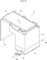
Fig. 11 is an upper perspective view of a measurement system according to the embodiment; -
Fig. 12 is an upper perspective view illustrating a state in which a part of an outer wall portion is removed from the measurement system ofFig. 11 ; -
Fig. 13 illustrates a cross section taken along line XIII-XIII ofFig. 12 ; -
Fig. 14 is a functional block diagram of the measurement system of the embodiment; -
Fig. 15 is a block diagram illustrating a controller; and -
Fig. 16 is a flowchart illustrating an overview of a measurement method of a measurement object in the measurement system of the embodiment. - Hereinafter, embodiments of the present disclosure will be described with reference to the drawings. The same reference signs in the drawings indicate the same portions without any particular description. Furthermore, each member and each portion illustrated in each drawing are merely schematically drawn, and the size and positional relationship of the actual product are not necessarily accurately expressed.
-
Fig. 1 is an upper perspective view illustrating aholding unit 40 used in a measurement system 10 (seeFig. 11 ) of the present embodiment. In themeasurement system 10 of the present disclosure, theholding unit 40 as illustrated inFig. 1 may be included as a member constituting a housing 20 (seeFig. 8 ). Theholding unit 40 has a box shape, and two openings of a measurement opening 43 and anidentification opening 44 are formed on an upper surface. Anoptical filter 45 is fitted into themeasurement opening 43. The upper surface is further provided with asensor 47 that senses light. Aninsertion gate 41 into which a test strip 60 (seeFig. 3 ) described later is inserted is opened in a side surface of theholding unit 40. An internal space of theinsertion gate 41 is aholder 46 that is a space in which a part of thetest strip 60 is accommodated, communicating with the measurement opening 43 and the identification opening 44. -
Fig. 2 is an enlarged lower perspective view of the vicinity of theinsertion gate 41 of theholding unit 40. Thesensor 47 is provided in the vicinity of the measurement opening 43 in theholder 46 that is the internal space of theinsertion gate 41. A measurement light source 42 (seeFig. 13 ) provided inside theholder 46 emits light including a light beam having a wavelength suitable for imaging afirst region 61. Then, theoptical filter 45 has an optical characteristic of suitably transmitting only a light beam having a wavelength suitable for the imaging. -
Fig. 3 illustrates thetest strip 60 used in the measurement system 10 (seeFig. 11 ) of the present embodiment in plan view. Thetest strip 60 has a flat rod-like outer shape. Agrip portion 65 whose upper surface side is recessed is formed at one end of thetest strip 60, and thetest strip 60 can be gripped with fingers by holding thegrip portion 65. Atest paper 64 having an elongated shape along a longitudinal direction of thetest strip 60 is accommodated in thetest strip 60. Thetest paper 64 is exposed upward at two openings formed on an upper surface of thetest strip 60. Among these two openings, a portion closer to thegrip portion 65 is asample spotting portion 63, and a portion farther from thegrip portion 65 is thefirst region 61 that is a measurement region where the measurement of a measurement object is performed. Moreover, asecond region 62 as an identification region in which information regarding thetest strip 60 is recorded is formed on the other end side of thetest strip 60, that is, on the upper surface of a place farthest from thegrip portion 65. Hereinafter, with respect to thetest strip 60, a side close to thegrip portion 65 is referred to as an "upstream side", and a side close to thesecond region 62 is referred to as a "downstream side". - The
test paper 64 is obtained by applying a water absorbing layer to a surface of a water absorbent such as filter paper or a synthetic resin substrate. Thetest paper 64 contains a reagent that reacts with a measurement object to develop color. A sample assumed to contain a measurement object is spotted to thesample spotting portion 63. Examples of the sample include a liquid specimen collected from a living body, for example, blood or urine, or a diluent obtained by diluting these with an appropriate solvent, or a solid or mucus collected from a living body, or a liquid specimen obtained by diluting or suspending these in an appropriate solvent. Examples of the measurement object include a component contained in the liquid specimen, or an antigen derived from an exogenous microorganism or virus. -
Fig. 4 is an upper perspective view illustrating a state in which thetest strip 60 is attached to theholding unit 40. Furthermore,Fig. 5 illustrates this state in plan view. As illustrated inFig. 4 andFig. 5 , thetest strip 60 is inserted into theholder 46 via theinsertion gate 41 with the downstream side first. In this state, as illustrated inFig. 5 , thefirst region 61 is at the same plane position as themeasurement opening 43, and thesecond region 62 is at the same plane position as theidentification opening 44. - In this state, for example, when the liquid specimen is spotted to the
sample spotting portion 63, the liquid specimen flows in thetest paper 64 to the downstream side by capillary phenomenon, and a control reaction zone indicating the spotting of the liquid specimen is generated in thefirst region 61. Moreover, in a case in which a measurement object is contained in the liquid specimen, a target reaction zone having a strength corresponding to a concentration of the measurement object is generated. Themeasurement system 10 of the present embodiment measures the concentration of the measurement object by irradiating the target reaction zone with light emitted from themeasurement light source 42 and measuring the intensity of the generated light. In thesecond region 62 described above, for example, identification information, which is information regarding thetest strip 60, such as what type of thetest sheet 64 is accommodated in thetest strip 60, is recorded. Examples of the identification information include a barcode, a QR code (registered trademark), and the like. -
Fig. 6 is an upper perspective view illustrating a mountingpart 30 used in the measurement system 10 (seeFig. 11 ) of the present embodiment. Furthermore,Fig. 7 illustrates the mountingpart 30 in bottom view. The mountingpart 30 is configured as a paper box having a substantially rectangular parallelepiped shape with an upper surface and a lower surface opened. Four side surfaces of the mountingpart 30 form anouter wall portion 34 erected vertically. Aplacement frame 32, which is a frame on which a smart device 50 (seeFig. 10 ) to be described later is placed, is formed on the upper surface of the mountingpart 30. On one side (Hereinafter, it is referred to as a "front side".) of the inside of the mountingpart 30, a box-shapedlight shielding portion 33 is formed in which the upper surface is closed while thewindow 31 is opened, and the lower surface is opened (seeFig. 7 ). - Here, among the four surfaces of the
outer wall portion 34, a surface on a side where thelight shielding portion 33 is located is referred to as afront surface 34a, a surface on an opposite side thereof is referred to as aback surface 34b, a surface on a left side when viewed from thefront surface 34a is referred to as aleft side surface 34c, and a surface on an opposite side thereof is referred to as aright side surface 34d. Furthermore, the inside of the mountingpart 30 is partitioned by a reinforcingportion 35 parallel to thefront surface 34a and theback surface 34b. Moreover, arectangular cutout portion 36 is formed at a front side lower edge of theleft side surface 34c. - As illustrated in
Fig. 7 , a gap is formed between a lower edge of thelight shielding portion 33 and a lower edge of theouter wall portion 34, and a space surrounded by thefront surface 34a, the reinforcingportion 35, theleft side surface 34c, and theright side surface 34d in four directions with this gap as a height is referred to as anaccommodation region 37. When the holdingunit 40 is attached to theaccommodation region 37, thehousing 20 illustrated inFig. 8 is configured. In this state, thecutout portion 36 of the mountingpart 30 and theinsertion gate 41 of the holdingunit 40 coincide with each other. A state in which thetest strip 60 is attached to theinsertion gate 41 in this state as illustrated inFig. 4 andFig. 5 is as illustrated in the upper perspective view illustrated inFig. 9 . -
Fig. 10 illustrates thesmart device 50 used in the measurement system 10 (seeFig. 11 ) of the present embodiment in a state of being placed on thehousing 20 in a bottom view. In the present embodiment, a smartphone is used as thesmart device 50. However, a tablet terminal with a camera function may be used as thesmart device 50. On the bottom surface side (so-called back surface) of thesmart device 50, acamera 51 configured as a camera and anilluminator 52 configured as a flash that emits visible light beside the camera are provided. Note that a top surface side (so-called surface) of thesmart device 50 is adisplay unit 53. - The
smart device 50 illustrated inFig. 10 is placed inside theplacement frame 32 of thehousing 20 illustrated inFig. 9 with thecamera 51 and theilluminator 52 aligned with thewindow 31 and thedisplay unit 53 facing upward, whereby themeasurement system 10 of the present embodiment as illustrated in the upper perspective view ofFig. 11 is configured. As illustrated in an upper perspective view ofFig. 12 illustrating a state in which thefront surface 34a, theleft side surface 34c, and theright side surface 34d of theouter wall portion 34 are removed from this state, themeasurement opening 43 and the identification opening 44 of the holdingunit 40 are covered with thelight shielding portion 33, and entry of light from the outside world is prevented. - Furthermore, as illustrated in
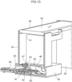
Fig. 13 illustrating a cross section taken along line XIII-XIII inFig. 12 , themeasurement opening 43 and theoptical filter 45 are located above thefirst region 61 of thetest strip 60, and the identification opening 44 is located above thesecond region 62. Moreover, themeasurement light source 42 that irradiates thefirst region 61 from obliquely above is installed on a slightly back surface side below theidentification opening 44. Thewindow 31 of the mountingpart 30 is positioned directly above themeasurement opening 43, and thecamera 51 of thesmart device 50 covers thesecond region 62 in addition to thefirst region 61 through the window. -
Fig. 14 is a functional block diagram illustrating themeasurement system 10 of the present embodiment. Thesmart device 50 is provided with thecamera 51 and theilluminator 52 illustrated inFig. 10 , thedisplay unit 53 illustrated inFig. 11 , and acontroller 100 that controls these units. Thecontroller 100 functions as the following units by using aCPU 110, aROM 120, aRAM 130, and astorage device 150 to be described later as hardware resources of a computer. - That is, the
controller 100 functions as anillumination switching unit 200 that switches on/off of illumination by theilluminator 52. Specifically, theillumination switching unit 200 can be realized as an application installed in thesmart device 50, but can also be realized as a unit using electric or optical sensing with the holdingunit 40 or as a wireless communication unit (for example, Bluetooth (registered trademark) or the like) with the holdingunit 40. Furthermore, thecontroller 100 functions as an imagingcondition storage unit 210 that stores imaging conditions by thecamera 51. Conditions defined as the imaging conditions include, for example, a standby time required for a reaction between the measurement object and the reagent. Furthermore, thecontroller 100 functions as a spottingdetection unit 220 that detects spotting of the sample on thetest strip 60 through thecamera 51. Furthermore, thecontroller 100 functions as a standbytime measurement unit 230 that measures the standby time. Then, thecontroller 100 functions as animage storage unit 240 that stores the image of thefirst region 61 captured by thecamera 51. - As illustrated in the hardware configuration of
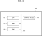
Fig. 15 , thecontroller 100 includes the central processing unit (CPU) 110, the read only memory (ROM) 120, the random access memory (RAM) 130, and thestorage device 150. The respective configurations are communicably connected to each other via abus 190. - The
CPU 110 is a central processing unit, and executes various programs and controls each unit. That is, theCPU 110 reads a program from theROM 120 or thestorage device 150, and executes the program using theRAM 130 as a work area. TheCPU 110 controls themeasurement system 10 according to a program recorded in theROM 120 or thestorage device 150. - The
ROM 120 stores various programs and various data. TheRAM 130 temporarily stores programs or data as a work area. Thestorage device 150 is configured as a storage by a hard disk drive (HDD), a solid state drive (SSD), or a flash memory, and stores various programs including an operating system and various data. - On the other hand, the holding
unit 40 includes themeasurement light source 42 that irradiates thefirst region 61, thesensor 47 that detects on/off of theilluminator 52, and alight source controller 48 that turns on themeasurement light source 42 when a signal from thesensor 47 is input. Similarly to thecontroller 100 of thesmart device 50, thelight source controller 48 is configured as a hardware resource of a computer. Note that thelight source controller 48 can realize that themeasurement light source 42 is turned on regardless of an input mode of the signal from the sensor 47 (for example, in a wired or wireless manner,) as long as it can perform control to turn on themeasurement light source 42 at the time of imaging thefirst region 61 to be described later. Furthermore, thelight source controller 48 can also perform control to turn off themeasurement light source 42. - As described above, the
measurement system 10 of the present embodiment includes theinsertion gate 41 into which thetest strip 60 including thefirst region 61 and thesecond region 62 is inserted, theholder 46 that accommodates thetest strip 60 inserted via theinsertion gate 41, thehousing 20 including thewindow 31 facing thetest strip 60 accommodated in theholder 46, and thesmart device 50 including theilluminator 52 that illuminates thesecond region 62 of thetest strip 60 accommodated in theholder 46 and including thecamera 51 that images thefirst region 61 and thesecond region 62. Thehousing 20 includes a mountingpart 30 that places thesmart device 50 on the outer surface of thehousing 20 in a state in which thecamera 51 and theilluminator 52 are disposed at positions facing thewindow 31, the holdingunit 40 that holds thetest strip 60 inside accommodated in theholder 46, and themeasurement light source 42 provided at a position to irradiate thefirst region 61 inside the holdingunit 40. Then, in themeasurement system 10, as will be described later, theilluminator 52 is turned off while themeasurement light source 42 is turned on when thecamera 51 images thefirst region 61, and theilluminator 52 is turned on when thecamera 51 images thesecond region 62. With such a configuration, in themeasurement system 10 of the present embodiment, in a case in which there are plural imaging regions (that is, thefirst region 61 and the second region 62) in thetest strip 60, imaging using an appropriate light source can be performed according to the imaging regions. - Here, the
controller 100 functioning as theillumination switching unit 200 that switches on/off of the illumination by theilluminator 52 can perform control to turn on theilluminator 52 at the time of imaging thesecond region 62 and to turn off theilluminator 52 at the time of imaging thefirst region 61. Furthermore, thelight source controller 48 can perform control to turn on themeasurement light source 42 at the time of imaging thefirst region 61. Furthermore, from the viewpoint of preventing exhaustion of themeasurement light source 42, thelight source controller 48 preferably performs control to turn off themeasurement light source 42 at the time of imaging thesecond region 62. - Here, as described above, the
first region 61 is a measurement region for measuring a measurement object in thetest strip 60, and thesecond region 62 is an identification region in which identification information of thetest strip 60 is recorded. In the measurement region, the measurement object in the sample is detected by color development by a reagent that specifically reacts with the measurement object in the target reaction zone, capture of the measurement object by a reagent that specifically binds to the measurement object, or the like. Examples of the identification region include a region to which a barcode, a QR code (registered trademark), or the like is attached. Examples of the identification information recorded in the identification region include the type of thetest paper 64 contained in thetest strip 60, measurement conditions suitable for thetest strip 60, lot information of thetest strip 60, and the like. Furthermore, themeasurement light source 42 is a light source suitable for detecting a measurement object in thefirst region 61 as a measurement region. For example, in a case in which a substance that reacts with the measurement object in the target reaction zone of thefirst region 61 absorbs ultraviolet light, themeasurement light source 42 can perform appropriate imaging by using ultraviolet light. Note that, as a result, themeasurement light source 42 having a wavelength corresponding to the measurement object can be used to image thefirst region 61 as the measurement region, and theilluminator 52 of thesmart device 50 can be used as the light source to image thesecond region 62 as the identification region. - Note that the
first region 61 is not limited to the measurement region, and may be an identification region as long as imaging can be appropriately performed under the lighting of themeasurement light source 42, or may be a correction region for measuring a light amount of themeasurement light source 42 or theilluminator 52 or the deterioration of thetest paper 64 and correcting the measurement of the measurement object, or may be other regions. Furthermore, thesecond region 62 is not limited to the identification information, and may be a measurement area, a correction area, or other areas as long as imaging can be appropriately performed under the lighting of theilluminator 52. Since theilluminator 52 is generally a flash of thesmart device 50 that emits visible light, thesecond region 62 is preferably a region including a measurement object that can be measured with visible light. - Note that, at the time of imaging the
second region 62 as the identification region by thecamera 51, it is preferable to turn off themeasurement light source 42 while turning on theilluminator 52. As a result, since themeasurement light source 42 can be turned on only when it is necessary to image thefirst region 61, the exhaustion of themeasurement light source 42 can be prevented. - An example of a method of measuring a measurement object by the
measurement system 10 of the present embodiment will be described with reference to a flowchart ofFig. 16 . Note that, in this flowchart, an outline of a stage indicating an operation other than an operation directly performed by thesmart device 50 is displayed in parentheses. - First, as illustrated in
Fig. 11 , themeasurement system 10 on which thesmart device 50 is placed is prepared in thehousing 20 in which the holdingunit 40 is attached to the mountingpart 30, and thetest strip 60 is inserted via theinsertion gate 41. At this stage, when a screen of the display unit 53 (seeFig. 11 andFig. 14 ) is operated, the application for measurement installed in thesmart device 50 is activated, and measurement is started. - First, at a stage illustrated in S100, the illumination switching unit 200 (see
Fig. 14 ) turns on theilluminator 52. At this stage, themeasurement light source 42 of the holdingunit 40 is turned off. Next, at a stage illustrated in S110, thecamera 51 captures an image of thesecond region 62, which is the identification region, using theilluminator 52 as a light source. When the image capturing is completed, the operation proceeds to a stage illustrated in S120. - In S120, the
controller 100 refers to the imaging condition storage unit 210 (seeFig. 14 ) from the captured image of thesecond region 62 to acquire the imaging conditions at the time of measurement by thetest strip 60. - Meanwhile, during this period, an appropriate amount of sample is spotted to the sample spotting portion 63 (see
Fig. 3 ) of thetest strip 60 by a measurer. The spotted sample is spread to the downstream side by the test paper 64 (seeFig. 3 ) inside thetest strip 60. - During this time, the spotting detection unit 220 (see
Fig. 14 ) of thecontroller 100 continues to monitor whether or not an image (for example, the control reaction zone generated by the reaction with the measurement object) indicating that spotting is completed is detected in thefirst region 61 that is the measurement region through the image from thecamera 51 in a stage illustrated in S 140. When such an image is detected, the operation proceeds to a stage illustrated in S150. - In the stage illustrated in S150, after the detection of the completion of the spotting in the step illustrated in S140, the standby time measurement unit 230 (see
Fig. 14 ) of thecontroller 100 continues to monitor whether or not the standby time required for the reaction between the measurement object and the reagent on thetest paper 64 has elapsed among the imaging conditions acquired in the stage illustrated in S120. - When the standby
time measurement unit 230 determines that the standby time has elapsed in the stage illustrated inS 150, theillumination switching unit 200 turns off theilluminator 52 in a stage illustrated in S160. - On the other hand, at a stage illustrated in S170, in the holding
unit 40, when thelight source controller 48 detects that theilluminator 52 is turned off through the sensor 47 (seeFig. 1 andFig. 14 ), themeasurement light source 42 is turned on. - When the
measurement light source 42 is turned on, thecamera 51 captures an image of the target reaction zone visualized at the wavelength of themeasurement light source 42 in thefirst region 61 in a stage illustrated in S180. When the image capturing is completed, thelight source controller 48 of the holdingunit 40 turns off themeasurement light source 42. Note that the captured image is stored in the image storage unit 240 (seeFig. 14 ), and then used to calculate the content of the measurement object. - In the
measurement system 10 of the above embodiment, thehousing 20 is formed by combining theseparate holding unit 40 with the mountingpart 30, but thehousing 20 may have a structure in which the mountingpart 30 and the holdingunit 40 are integrated. In this case, thehousing 20 is provided with theinsertion gate 41, and a space provided at the back serves as theholder 46. Then, thetest strip 60 is inserted via theinsertion gate 41, and thefirst region 61 and thesecond region 62 of thetest strip 60 accommodated in theholder 46 are used for imaging by thecamera 51 of thesmart device 50 as in the above-described embodiment. - Furthermore, the
test strip 60 has a structure in which thetest paper 64 is accommodated inside as described in the above embodiment, but for example, thetest paper 64 itself such as a urine test paper may be used as thetest strip 60. In this case, not only thefirst region 61 but also thesecond region 62 is provided on thetest paper 64 as thetest strip 60. Furthermore, in this case, as a material of thetest paper 64, as described in the above embodiment, a water absorber such as a filter paper or a synthetic resin substrate having a water absorbing layer applied on the surface thereof can be used. - The present invention can be used for a measurement system that spreads a measurement object in a sample with a test strip and optically detects the measurement object.
Claims (6)
- A measurement system (10) comprising:an insertion gate (41) into which a test strip (60) including a first region (61) and a second region (62) is to be inserted;a holder (46) that accommodates the test strip (60) inserted via the insertion gate (41);a housing (20) including a window (31) facing the test strip (60) accommodated in the holder (46); anda smart device (50) including an illuminator (52) that illuminates the second region (62) of the test strip (60) accommodated in the holder (46) and including a camera (51) that images the first region (61) and the second region (62),wherein the housing (20) includes a mounting part (30) that places the smart device (50) on an outer surface of the housing (20) in a state in which the camera (51) and the illuminator (52) are disposed at positions facing the window (31), and a measurement light source (42) provided at a position to irradiate the first region (61) of the test strip (60) accommodated in the holder (46), andin a case in which the camera (51) images the first region (61), the illuminator (52) is turned off while the measurement light source (42) is turned on, and in a case in which the camera (51) images the second region (62), the illuminator (52) is turned on.
- The measurement system (10) according to claim 1, wherein, in a case in which the camera (51) images the second region (62), the measurement light source (42) is turned off while the illuminator (52) is turned on.
- The measurement system (10) according to claim 1 or 2, wherein:the smart device (50) includes a controller (100) that turns on the illuminator (52) at a time of imaging the second region (62) and turns off the illuminator (52) at a time of imaging the first region (61), andthe housing (20) includes a light source controller (48) that turns on the measurement light source (42) at the time of imaging the first region (61) and turns off the measurement light source (42) at the time of imaging the second region (62).
- The measurement system (10) according to any one of claims 1 to 3, wherein the first region (61) is a measurement region in which a measurement object contained in a sample spotted on the test strip (60) is measured, and the second region (62) is an identification region in which identification information related to the test strip (60) is recorded.
- The measurement system (10) according to claim 4, wherein the measurement light source (42) is a measurement light source (42) suitable for detecting the measurement object in the measurement region.
- A measurement method using the measurement system (10) according to any one of claims 3 to 5, the measurement method comprising:the controller (100) turning on the illuminator (52);the camera (51) imaging the second region (62) of the test strip (60) inserted into the housing (20);the controller (100) turning off the illuminator (52);the light source controller (48) turning on the measurement light source (42);the camera (51) imaging the first region (61) illuminated by the measurement light source (42); andthe light source controller (48) turning off the measurement light source (42).
Applications Claiming Priority (1)
| Application Number | Priority Date | Filing Date | Title |
|---|---|---|---|
| JP2022168628A JP2024060999A (en) | 2022-10-20 | 2022-10-20 | Measurement system and method |
Publications (1)
| Publication Number | Publication Date |
|---|---|
| EP4357763A1 true EP4357763A1 (en) | 2024-04-24 |
Family
ID=88237664
Family Applications (1)
| Application Number | Title | Priority Date | Filing Date |
|---|---|---|---|
| EP23201193.2A Pending EP4357763A1 (en) | 2022-10-20 | 2023-10-02 | Measurement system and measurement method |
Country Status (4)
| Country | Link |
|---|---|
| US (1) | US12613193B2 (en) |
| EP (1) | EP4357763A1 (en) |
| JP (1) | JP2024060999A (en) |
| CN (1) | CN117917559A (en) |
Citations (6)
| Publication number | Priority date | Publication date | Assignee | Title |
|---|---|---|---|---|
| US20130203043A1 (en) * | 2012-02-06 | 2013-08-08 | The Regents Of The University Of California | Portable rapid diagnostic test reader |
| JP2015070572A (en) | 2013-09-30 | 2015-04-13 | 株式会社Pfu | Image reading device |
| US20170023542A1 (en) * | 2015-07-26 | 2017-01-26 | Naishu Wang | Smartphone dock and diagnostic-test reader plus related methods |
| WO2020003021A1 (en) | 2018-06-28 | 2020-01-02 | International Business Machines Corporation | Accurate colorimetric based test strip reader system |
| WO2020231159A1 (en) * | 2019-05-15 | 2020-11-19 | 프리시젼바이오 주식회사 | Immunoassay device |
| US20220065795A1 (en) * | 2019-01-15 | 2022-03-03 | Quidel Corporation | System and methods for remote assessment of a sample assay for disease diagnostics |
Family Cites Families (2)
| Publication number | Priority date | Publication date | Assignee | Title |
|---|---|---|---|---|
| US20160370366A1 (en) * | 2010-07-20 | 2016-12-22 | Quantrx Biomedical Corporation | Optical reader systems and lateral flow assays |
| US20230243820A1 (en) * | 2022-02-01 | 2023-08-03 | Wallac Oy | Lateral flow test strip reader and related methods |
-
2022
- 2022-10-20 JP JP2022168628A patent/JP2024060999A/en active Pending
-
2023
- 2023-10-02 EP EP23201193.2A patent/EP4357763A1/en active Pending
- 2023-10-02 US US18/479,273 patent/US12613193B2/en active Active
- 2023-10-18 CN CN202311356299.XA patent/CN117917559A/en active Pending
Patent Citations (6)
| Publication number | Priority date | Publication date | Assignee | Title |
|---|---|---|---|---|
| US20130203043A1 (en) * | 2012-02-06 | 2013-08-08 | The Regents Of The University Of California | Portable rapid diagnostic test reader |
| JP2015070572A (en) | 2013-09-30 | 2015-04-13 | 株式会社Pfu | Image reading device |
| US20170023542A1 (en) * | 2015-07-26 | 2017-01-26 | Naishu Wang | Smartphone dock and diagnostic-test reader plus related methods |
| WO2020003021A1 (en) | 2018-06-28 | 2020-01-02 | International Business Machines Corporation | Accurate colorimetric based test strip reader system |
| US20220065795A1 (en) * | 2019-01-15 | 2022-03-03 | Quidel Corporation | System and methods for remote assessment of a sample assay for disease diagnostics |
| WO2020231159A1 (en) * | 2019-05-15 | 2020-11-19 | 프리시젼바이오 주식회사 | Immunoassay device |
Non-Patent Citations (1)
| Title |
|---|
| YAFEI HOU ET AL: "Smartphone-Based Dual-Modality Imaging System for Quantitative Detection of Color or Fluorescent Lateral Flow Immunochromatographic Strips", NANOSCALE RESEARCH LETTERS, SPRINGER, US, vol. 12, no. 1, 21 April 2017 (2017-04-21), pages 1 - 13, XP021244394, ISSN: 1931-7573, DOI: 10.1186/S11671-017-2078-9 * |
Also Published As
| Publication number | Publication date |
|---|---|
| US20240133820A1 (en) | 2024-04-25 |
| CN117917559A (en) | 2024-04-23 |
| JP2024060999A (en) | 2024-05-07 |
| US20240230548A9 (en) | 2024-07-11 |
| US12613193B2 (en) | 2026-04-28 |
Similar Documents
| Publication | Publication Date | Title |
|---|---|---|
| EP4067473B1 (en) | Assay reader based on human perception and method relating thereto | |
| KR101530114B1 (en) | Analyzing device | |
| JP2016522880A (en) | System and method for in vitro detection of particles and soluble chemicals in body fluids | |
| CN104081210A (en) | Optical assay device with pneumatic sample actuation | |
| EP4099002A1 (en) | Chromatographic inspection apparatus and control method thereof | |
| US20160116465A1 (en) | Fluorescence excitation device and portable fluorescence analysis system with the same | |
| US20120207653A1 (en) | Test instrument and optical measurement apparatus | |
| US20240139730A1 (en) | Measurement system | |
| WO2011122606A1 (en) | Sample analysis system | |
| US12613193B2 (en) | Measurement system and measurement method | |
| US20170254804A1 (en) | Portable fluorescence detection system | |
| EP4465023A1 (en) | Measurement method and measurement system | |
| US20220299445A1 (en) | Screening Test Paper Reading System | |
| JP2024163032A (en) | Measurement method and measurement system | |
| JP2024066459A (en) | Measurement System | |
| US20240299946A1 (en) | Ready to use analyzer control product for cua urinalysis instruments | |
| EP4549916A1 (en) | Measurement system, measurement method, measurement program, and smart device | |
| EP4549917A1 (en) | Measurement system | |
| CN119421749A (en) | Analyzer with transparent barrier for protecting imaging system | |
| CN118937220A (en) | Measurement method and measurement system | |
| EP4664097A1 (en) | Determination system, test strip, and fluorescence reference strip | |
| CN117949382A (en) | Measurement system | |
| WO2022210312A1 (en) | Testing device | |
| KR20230067592A (en) | Diagnostic cartridge for immunodiagnosis and diagnostic device and system using the same | |
| WO2022203017A1 (en) | Immunochromatography testing device |
Legal Events
| Date | Code | Title | Description |
|---|---|---|---|
| PUAI | Public reference made under article 153(3) epc to a published international application that has entered the european phase |
Free format text: ORIGINAL CODE: 0009012 |
|
| STAA | Information on the status of an ep patent application or granted ep patent |
Free format text: STATUS: THE APPLICATION HAS BEEN PUBLISHED |
|
| AK | Designated contracting states |
Kind code of ref document: A1 Designated state(s): AL AT BE BG CH CY CZ DE DK EE ES FI FR GB GR HR HU IE IS IT LI LT LU LV MC ME MK MT NL NO PL PT RO RS SE SI SK SM TR |
|
| STAA | Information on the status of an ep patent application or granted ep patent |
Free format text: STATUS: REQUEST FOR EXAMINATION WAS MADE |
|
| 17P | Request for examination filed |
Effective date: 20241022 |
|
| RBV | Designated contracting states (corrected) |
Designated state(s): AL AT BE BG CH CY CZ DE DK EE ES FI FR GB GR HR HU IE IS IT LI LT LU LV MC ME MK MT NL NO PL PT RO RS SE SI SK SM TR |
|
| STAA | Information on the status of an ep patent application or granted ep patent |
Free format text: STATUS: EXAMINATION IS IN PROGRESS |
|
| 17Q | First examination report despatched |
Effective date: 20250620 |