EP4357703A1 - Gas-liquid separator and air conditioning device - Google Patents
Gas-liquid separator and air conditioning device Download PDFInfo
- Publication number
- EP4357703A1 EP4357703A1 EP22824133.7A EP22824133A EP4357703A1 EP 4357703 A1 EP4357703 A1 EP 4357703A1 EP 22824133 A EP22824133 A EP 22824133A EP 4357703 A1 EP4357703 A1 EP 4357703A1
- Authority
- EP
- European Patent Office
- Prior art keywords
- fixed frame
- outlet pipe
- air outlet
- connector
- gas
- Prior art date
- Legal status (The legal status is an assumption and is not a legal conclusion. Google has not performed a legal analysis and makes no representation as to the accuracy of the status listed.)
- Pending
Links
Images


Classifications
-
- F—MECHANICAL ENGINEERING; LIGHTING; HEATING; WEAPONS; BLASTING
- F25—REFRIGERATION OR COOLING; COMBINED HEATING AND REFRIGERATION SYSTEMS; HEAT PUMP SYSTEMS; MANUFACTURE OR STORAGE OF ICE; LIQUEFACTION SOLIDIFICATION OF GASES
- F25B—REFRIGERATION MACHINES, PLANTS OR SYSTEMS; COMBINED HEATING AND REFRIGERATION SYSTEMS; HEAT PUMP SYSTEMS
- F25B43/00—Arrangements for separating or purifying gases or liquids; Arrangements for vaporising the residuum of liquid refrigerant, e.g. by heat
- F25B43/006—Accumulators
-
- F—MECHANICAL ENGINEERING; LIGHTING; HEATING; WEAPONS; BLASTING
- F25—REFRIGERATION OR COOLING; COMBINED HEATING AND REFRIGERATION SYSTEMS; HEAT PUMP SYSTEMS; MANUFACTURE OR STORAGE OF ICE; LIQUEFACTION SOLIDIFICATION OF GASES
- F25B—REFRIGERATION MACHINES, PLANTS OR SYSTEMS; COMBINED HEATING AND REFRIGERATION SYSTEMS; HEAT PUMP SYSTEMS
- F25B43/00—Arrangements for separating or purifying gases or liquids; Arrangements for vaporising the residuum of liquid refrigerant, e.g. by heat
-
- F—MECHANICAL ENGINEERING; LIGHTING; HEATING; WEAPONS; BLASTING
- F25—REFRIGERATION OR COOLING; COMBINED HEATING AND REFRIGERATION SYSTEMS; HEAT PUMP SYSTEMS; MANUFACTURE OR STORAGE OF ICE; LIQUEFACTION SOLIDIFICATION OF GASES
- F25B—REFRIGERATION MACHINES, PLANTS OR SYSTEMS; COMBINED HEATING AND REFRIGERATION SYSTEMS; HEAT PUMP SYSTEMS
- F25B43/00—Arrangements for separating or purifying gases or liquids; Arrangements for vaporising the residuum of liquid refrigerant, e.g. by heat
- F25B43/003—Filters
-
- F—MECHANICAL ENGINEERING; LIGHTING; HEATING; WEAPONS; BLASTING
- F25—REFRIGERATION OR COOLING; COMBINED HEATING AND REFRIGERATION SYSTEMS; HEAT PUMP SYSTEMS; MANUFACTURE OR STORAGE OF ICE; LIQUEFACTION SOLIDIFICATION OF GASES
- F25B—REFRIGERATION MACHINES, PLANTS OR SYSTEMS; COMBINED HEATING AND REFRIGERATION SYSTEMS; HEAT PUMP SYSTEMS
- F25B2400/00—Component parts or details not otherwise provided for in this subclass
- F25B2400/23—Separators
-
- F—MECHANICAL ENGINEERING; LIGHTING; HEATING; WEAPONS; BLASTING
- F25—REFRIGERATION OR COOLING; COMBINED HEATING AND REFRIGERATION SYSTEMS; HEAT PUMP SYSTEMS; MANUFACTURE OR STORAGE OF ICE; LIQUEFACTION SOLIDIFICATION OF GASES
- F25B—REFRIGERATION MACHINES, PLANTS OR SYSTEMS; COMBINED HEATING AND REFRIGERATION SYSTEMS; HEAT PUMP SYSTEMS
- F25B2500/00—Problems to be solved
- F25B2500/18—Optimization, e.g. high integration of refrigeration components
Definitions
- the present invention generally relates to the field of refrigeration, and in particular, to a gas-liquid separator and an air conditioning device.
- a gas-liquid separator includes a shell, an air outlet pipe, and a fixed frame.
- the shell is provided with a liquid storage chamber
- the air outlet pipe is disposed in the liquid storage chamber and provided with a filtering member for filtering media entering the air outlet pipe by a filter port.
- the air outlet pipe is fixedly connected to the shell by the fixed frame, the air outlet pipe is in a shape of U, and a bottom end of the U-shaped air outlet pipe is clamped to the fixed frame.
- the shape of the air outlet pipe is irregular and a volume thereof is large, so it is difficult to connect the air outlet pipe to the fixed frame, which in turn makes it difficult to connect the air outlet pipe to the shell.
- a gas-liquid separator and an air conditioning device are provided.
- the present invention provides a gas-liquid separator, including a shell, an air outlet pipe, a filter member, and a fixed frame.
- the shell is provided with a liquid storage chamber.
- the air outlet pipe is at least partially disposed in the liquid storage chamber, and a portion of the air outlet pipe located in the liquid storage chamber is provided with a filter port.
- the filter member is fixedly connected to the filter port of the air outlet pipe to filter medium entering the air outlet pipe from the filter port.
- the fixed frame is fixedly connected to the shell and the filter member.
- the filter member includes a screen, a connector, and a main seat body connecting to the screen and the connector, and the connector extends into the filter port and is fixedly connected to the air outlet pipe.
- the fixed frame is provided with a clamp hole, and the fixed frame is sheathed on an outside of the connector by the clamp hole.
- a portion of the fixed frame provided with the clamp hole abuts between the air outlet pipe and the main seat body.
- an end of the fixed frame is connected to an inner wall of the shell by welding, and the other end of the fixed frame is provided with the clamp hole.
- the fixed frame comprises a first connecting plate and a second connecting plate connected in a shape of L, an end of the first connecting plate away from the second connecting plate is connected to the shell, and an end of the second connecting plate away from the first connecting plate is connected to the filter member.
- both ends of the fixed frame are connected to an inner wall of the shell by welding, and the clamp hole is located at a center of the fixed frame.
- both ends of the fixed frame are bent at 90° to form a flap structure, and the fixed frame is welded to the shell by the flap structure.
- an inner diameter of the clamp hole is denoted as d
- a width of the fixed frame is denoted as h
- the inner diameter d of the clamp hole and the width h of the fixed frame satisfy the following relational formula: 0.3h ⁇ d ⁇ 0.7h.
- the main seat body is in a shape of a conical pipe, and an outer diameter of the main seat body gradually increases from an end of the main seat body proximal to the connector to the other end of the main seat body away from the connector;
- the screen is in a shape of a cylinder, and the screen is disposed on the end of the main seat body away from the connector.
- the present invention further provides an air conditioning device, including the gas-liquid separator of any one of the above embodiments.
- 100 represents a gas-liquid separator
- 1 represents a shell
- 11 represents a liquid storage chamber
- 2 represents an air outlet pipe
- 21 represents a filter port
- 3 represents a filter member
- 31 represents a main seat body
- 32 represents a screen
- 33 represents a connector
- 4 represents a fixed frame
- 41 represents a clamp hole
- 42 represents a first connecting plate
- 43 represents a second connecting plate
- 44 represents a flap structure
- 200 represents an air conditioning device.
- an assembly when an assembly is considered to be “disposed on” another assembly, it can be directly disposed to another assembly, or there can be a centered assembly.
- an assembly When an assembly is considered to be “set on” another assembly, it can be directly set on another assembly, or there can be a centered assembly at the same time.
- an assembly When an assembly is considered to be “fixed to” another assembly, it can be directly fixed to another assembly, or there can be a centered assembly at the same time.
- the present invention provides a gas-liquid separator 100, including a shell 1, a flow inlet pipe (not shown), an air outlet pipe 2, a filter member 3, and a fixed frame 4.
- the shell 1 is provided with a liquid storage chamber 11.
- the air outlet pipe 2 is at least partially disposed in the liquid storage chamber 11, and a portion of the air outlet pipe 2 located in the liquid storage chamber 11 is provided with a filter port 21.
- the filter member 3 is fixedly connected to the filter port 21 of the air outlet pipe 2 to filter medium entering the air outlet pipe 2 from the filter port 21.
- refrigerant with two phases of gas and liquid may enter the liquid storage chamber 11 from the flow inlet pipe, and the refrigerant may be mixed with some lubricating oil for a compressor. After the refrigerant enters the liquid storage chamber 11, gaseous refrigerant may rise and enter the air outlet pipe 2, and liquid refrigerant mixed with the lubricating oil may directly sink into a bottom of the liquid storage chamber 11. A density of the liquid refrigerant and a density of the lubricating oil are different, and the liquid refrigerant and the lubricating oil are not miscible.
- the liquid refrigerant and the lubricating oil would be stratified under an action of gravity, and the lubricating oil would float above the liquid refrigerant. After that, the lubricating oil may enter the outlet pipe 2 by the filter member 3 and return to the compressor together with the gaseous refrigerant.
- the liquid refrigerant remaining at the bottom of the liquid storage chamber 11 may also rise in the liquid storage chamber 11 and enter the air outlet pipe 2 after gasification, and finally return to the compressor.
- the fixed frame 4 is fixedly connected to the shell 1 and the filter member 3, thereby realizing a fixed connection between the air outlet pipe 2 and the shell 1.
- the fixed frame 4 is easier to be fixedly connected to the filter member 3, and the fixed frame 4 and the filter member 3 have low connection difficulty. Therefore, in the present invention, the fixed frame 4 is fixedly connected to the filter member 3, greatly reducing connection difficulty between the air outlet pipe 2 and the shell 1.
- fixed connection may include welding and clamping.
- the filter member 3 may be clamped at the filter port 21 of the air outlet pipe 2, or be connected to the filter port 21 of the air outlet pipe 2 by welding.
- the fixed frame 4 may be connected to the shell 1 by welding, or be clamped to the shell.
- the fixed frame 4 may be connected to the filter member 3 by welding, or be clamped to the filter member 3.
- the fixed connection may also include screw connection, rivet connection and other connection manners.
- the filter member 3 may include a screen 32, a connector 33, and a main seat body 31 connecting to the screen 32 and the connector 33, and the connector 33 may extend into the filter port 21 and be fixedly connected to the air outlet pipe 2.
- the filter member 3 may extend into the filter port 21 by the connector 33 and be fixedly connected to the air outlet pipe 2, thereby increasing connection strength between the filter member 3 and the air outlet pipe 2.
- the main seat body 31 may be in a shape of a conical pipe, and an outer diameter of the main seat body 31 may gradually increase from an end of the main seat body 31 proximal to the connector 33 to the other end of the main seat body 31 away from the connector 33.
- the screen 32 may be in a shape of a cylinder, and the screen 32 may be disposed on the end of the main seat body 31 away from the connector 33. In this way, it facilitates increasing filter area of the screen 32 and effectively improving oil return efficiency of the gas-liquid separator 100.
- the fixed frame 4 may be provided with a clamp hole 41, and the fixed frame 4 may be sheathed on an outside of the connector 33 by the clamp hole 41. In this way, the fixed frame 4 and filter member 3 may be more firmly assembled.
- the fixed frame 4 may be first sheathed on the outside of the connector 33 by the clamp hole 41, and then the connector 33 may be inserted into the filter port 21 and be fixedly connected to the air outlet pipe 2.
- the outside of the connector 33 may be connected at the clamp hole 41 of the fixed frame 4 by welding, further improving connection firmness between the fixed frame 4 and the filter member 3.
- a portion of the fixed frame 4 provided with the clamp hole 41 may abut between the air outlet pipe 2 and the main seat body 31. In this way, an end of the fixed frame 4 connected to the filter member 3 may be not easy to loosen, thereby effectively improving structural strength of the gas-liquid separator 100.
- an end of the fixed frame 4 may be connected to an inner wall of the shell 1 by welding, and the other end of the fixed frame 4 may be provided with the clamp hole 41.
- the end of the fixed frame 4 may be connected to the shell 1, and the other end of the fixed frame 4 may be connected to the filter member 3.
- the fixed frame may have a simpler structure, which facilitates processing and manufacturing of the gas-liquid separator 100.
- the fixed frame 4 may include a first connecting plate 42 and a second connecting plate 43 connected in a shape of L, an end of the first connecting plate 42 away from the second connecting plate 43 may be connected to the shell 1, and an end of the second connecting plate 43 away from the first connecting plate 42 may be connected to the filter member 3. In this way, it may improve structural strength of the fixed frame 4, so that the fixed frame 4 may be not easy to bend and deform.
- both ends of the fixed frame 4 may be connected to an inner wall of the shell 1 by welding, and the clamp hole 41 may be located at a center of the fixed frame 4. In this way, it may increase welding points between the fixed frame 4 and the shell 1, and improve connection strength between the fixed frame 4 and the shell 1.
- both ends of the fixed frame 4 may be bent at 90° to form a flap structure 44, and the fixed frame 4 may be connected to the shell 1 by the flap structure 44 in a welding manner. In this way, it may further improve welding area between the fixed frame 4 and the shell 1, and increase welding strength between the fixed frame 4 and the shell 1.
- an inner diameter of the clamp hole 41 may be denoted as d
- a width of the fixed frame 4 may be denoted as h
- the inner diameter d of the clamp hole 41 and the width h of the fixed frame 4 may satisfy the following relational formula: 0.3h ⁇ d ⁇ 0.7h.
- d ⁇ 0.3h i.e., h ⁇ 10d/3.
- d ⁇ 0.7h thereby avoiding the inner diameter of the clamp hole 41 being too great to affect structural strength of the fixed frame 4.
- the present invention further provides an air conditioning device 200, including the gas-liquid separator 100 in any one of the above embodiments.
- the fixed frame 4 is fixedly connected to the shell 1 and the filter member 3, thereby realizing a fixed connection between the air outlet pipe 2 and the shell 1.
- the fixed frame 4 is easier to be fixedly connected to the filter member 3, and the fixed frame 4 and the filter member 3 have low connection difficulty. Therefore, in the present invention, the fixed frame 4 is fixedly connected to the filter member 3, greatly reducing connection difficulty between the air outlet pipe 2 and the shell 1.
Landscapes
- Engineering & Computer Science (AREA)
- Physics & Mathematics (AREA)
- Mechanical Engineering (AREA)
- Thermal Sciences (AREA)
- General Engineering & Computer Science (AREA)
- Chemical & Material Sciences (AREA)
- Analytical Chemistry (AREA)
- Power Engineering (AREA)
- Filtering Of Dispersed Particles In Gases (AREA)
Abstract
Description
- This application claims priority to
Chinese patent application No. 202110665946.X, filed on June 16, 2021 - The present invention generally relates to the field of refrigeration, and in particular, to a gas-liquid separator and an air conditioning device.
- A gas-liquid separator includes a shell, an air outlet pipe, and a fixed frame. The shell is provided with a liquid storage chamber, and the air outlet pipe is disposed in the liquid storage chamber and provided with a filtering member for filtering media entering the air outlet pipe by a filter port. Typically, the air outlet pipe is fixedly connected to the shell by the fixed frame, the air outlet pipe is in a shape of U, and a bottom end of the U-shaped air outlet pipe is clamped to the fixed frame. However, the shape of the air outlet pipe is irregular and a volume thereof is large, so it is difficult to connect the air outlet pipe to the fixed frame, which in turn makes it difficult to connect the air outlet pipe to the shell.
- According to various embodiments of the present invention, a gas-liquid separator and an air conditioning device are provided.
- The present invention provides a gas-liquid separator, including a shell, an air outlet pipe, a filter member, and a fixed frame. The shell is provided with a liquid storage chamber. The air outlet pipe is at least partially disposed in the liquid storage chamber, and a portion of the air outlet pipe located in the liquid storage chamber is provided with a filter port. The filter member is fixedly connected to the filter port of the air outlet pipe to filter medium entering the air outlet pipe from the filter port. The fixed frame is fixedly connected to the shell and the filter member.
- In an embodiment of the present invention, the filter member includes a screen, a connector, and a main seat body connecting to the screen and the connector, and the connector extends into the filter port and is fixedly connected to the air outlet pipe.
- In an embodiment of the present invention, the fixed frame is provided with a clamp hole, and the fixed frame is sheathed on an outside of the connector by the clamp hole.
- In an embodiment of the present invention, a portion of the fixed frame provided with the clamp hole abuts between the air outlet pipe and the main seat body.
- In an embodiment of the present invention, an end of the fixed frame is connected to an inner wall of the shell by welding, and the other end of the fixed frame is provided with the clamp hole.
- In an embodiment of the present invention, the fixed frame comprises a first connecting plate and a second connecting plate connected in a shape of L, an end of the first connecting plate away from the second connecting plate is connected to the shell, and an end of the second connecting plate away from the first connecting plate is connected to the filter member.
- In an embodiment of the present invention, both ends of the fixed frame are connected to an inner wall of the shell by welding, and the clamp hole is located at a center of the fixed frame.
- In an embodiment of the present invention, both ends of the fixed frame are bent at 90° to form a flap structure, and the fixed frame is welded to the shell by the flap structure.
- In an embodiment of the present invention, an inner diameter of the clamp hole is denoted as d, a width of the fixed frame is denoted as h, and the inner diameter d of the clamp hole and the width h of the fixed frame satisfy the following relational formula: 0.3h ≤ d ≤ 0.7h.
- In an embodiment of the present invention, the main seat body is in a shape of a conical pipe, and an outer diameter of the main seat body gradually increases from an end of the main seat body proximal to the connector to the other end of the main seat body away from the connector; the screen is in a shape of a cylinder, and the screen is disposed on the end of the main seat body away from the connector.
- The present invention further provides an air conditioning device, including the gas-liquid separator of any one of the above embodiments.
- Details of one or more embodiments of the present invention are set forth in the following accompanying drawings and description. Other features, objects, and advantages of the present invention will become apparent from the description, the accompanying drawings, and the claims.
- Reference may be made to one or more of the accompanying drawings for a purpose of better describing and illustrating the embodiments and/or examples of those applications disclosed herein. Additional details or examples used to describe the accompanying drawings should not be considered a limitation on the scope of any of the disclosed applications, the embodiments and/or examples presently described, and the best mode of these applications as presently understood.
-
FIG. 1 is a sectional diagram of a gas-liquid separator according to one or more embodiments. -
FIG. 2 is an enlarged diagram of A as shown inFIG. 1 . -
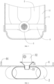
FIG. 3 is a first schematic diagram of a fixed frame according to one or more embodiments. -
FIG. 4 is a second schematic diagram of a fixed frame according to one or more embodiments. -
FIG. 5 is a first sectional diagram of a gas-liquid separator according to one or more embodiments. -
FIG. 6 is a second sectional diagram of a gas-liquid separator according to one or more embodiments. -
FIG. 7 is a schematic diagram of a fixed frame according to one or more embodiments. -
FIG. 8 is a schematic diagram of an air conditioning device according to one or more embodiments. - In the figures, 100 represents a gas-liquid separator, 1 represents a shell, 11 represents a liquid storage chamber, 2 represents an air outlet pipe, 21 represents a filter port, 3 represents a filter member, 31 represents a main seat body, 32 represents a screen, 33 represents a connector, 4 represents a fixed frame, 41 represents a clamp hole, 42 represents a first connecting plate, 43 represents a second connecting plate, 44 represents a flap structure, 200 represents an air conditioning device.
- The technical solutions in the embodiments of the present invention are clearly and completely described in the following with reference to the accompanying drawings in the embodiments of the present invention. It is obvious that the described embodiments are only a part of the embodiments, but not all of the embodiments. All other embodiments obtained by those skilled in the art based on the embodiments of the present invention without making creative labor are the scope of the present invention.
- It should be noted that when an assembly is considered to be "disposed on" another assembly, it can be directly disposed to another assembly, or there can be a centered assembly. When an assembly is considered to be "set on" another assembly, it can be directly set on another assembly, or there can be a centered assembly at the same time. When an assembly is considered to be "fixed to" another assembly, it can be directly fixed to another assembly, or there can be a centered assembly at the same time.
- Unless otherwise defined, all technical and scientific terms used herein have the same meaning as a skilled person in the art would understand. The terminology used in the description of the present invention is for the purpose of describing particular embodiments and is not intended to limit the invention. The term "and/or" as used herein includes any and all combinations of one or more of the associated listed items.
- Referring to
FIG. 1 ,FIG. 2 ,FIG. 5, and FIG. 6 , the present invention provides a gas-liquid separator 100, including ashell 1, a flow inlet pipe (not shown), anair outlet pipe 2, afilter member 3, and afixed frame 4. Theshell 1 is provided with aliquid storage chamber 11. Theair outlet pipe 2 is at least partially disposed in theliquid storage chamber 11, and a portion of theair outlet pipe 2 located in theliquid storage chamber 11 is provided with afilter port 21. Thefilter member 3 is fixedly connected to thefilter port 21 of theair outlet pipe 2 to filter medium entering theair outlet pipe 2 from thefilter port 21. - Typically, refrigerant with two phases of gas and liquid may enter the
liquid storage chamber 11 from the flow inlet pipe, and the refrigerant may be mixed with some lubricating oil for a compressor. After the refrigerant enters theliquid storage chamber 11, gaseous refrigerant may rise and enter theair outlet pipe 2, and liquid refrigerant mixed with the lubricating oil may directly sink into a bottom of theliquid storage chamber 11. A density of the liquid refrigerant and a density of the lubricating oil are different, and the liquid refrigerant and the lubricating oil are not miscible. Therefore, at the bottom of theliquid storage chamber 11, the liquid refrigerant and the lubricating oil would be stratified under an action of gravity, and the lubricating oil would float above the liquid refrigerant. After that, the lubricating oil may enter theoutlet pipe 2 by thefilter member 3 and return to the compressor together with the gaseous refrigerant. The liquid refrigerant remaining at the bottom of theliquid storage chamber 11 may also rise in theliquid storage chamber 11 and enter theair outlet pipe 2 after gasification, and finally return to the compressor. - In the present embodiment, referring to
FIG. 1 ,FIG. 2 ,FIG. 5, and FIG. 6 , since theair outlet pipe 2 is fixedly connected to thefilter member 3, thefixed frame 4 is fixedly connected to theshell 1 and thefilter member 3, thereby realizing a fixed connection between theair outlet pipe 2 and theshell 1. Compared with theair outlet pipe 2, thefixed frame 4 is easier to be fixedly connected to thefilter member 3, and thefixed frame 4 and thefilter member 3 have low connection difficulty. Therefore, in the present invention, thefixed frame 4 is fixedly connected to thefilter member 3, greatly reducing connection difficulty between theair outlet pipe 2 and theshell 1. - It should be noted that fixed connection may include welding and clamping. In other words, the
filter member 3 may be clamped at thefilter port 21 of theair outlet pipe 2, or be connected to thefilter port 21 of theair outlet pipe 2 by welding. Similarly, the fixedframe 4 may be connected to theshell 1 by welding, or be clamped to the shell. The fixedframe 4 may be connected to thefilter member 3 by welding, or be clamped to thefilter member 3. Not limited to the above, the fixed connection may also include screw connection, rivet connection and other connection manners. - Furthermore, referring to
FIG. 2 , thefilter member 3 may include ascreen 32, aconnector 33, and amain seat body 31 connecting to thescreen 32 and theconnector 33, and theconnector 33 may extend into thefilter port 21 and be fixedly connected to theair outlet pipe 2. Thefilter member 3 may extend into thefilter port 21 by theconnector 33 and be fixedly connected to theair outlet pipe 2, thereby increasing connection strength between thefilter member 3 and theair outlet pipe 2. Specifically, themain seat body 31 may be in a shape of a conical pipe, and an outer diameter of themain seat body 31 may gradually increase from an end of themain seat body 31 proximal to theconnector 33 to the other end of themain seat body 31 away from theconnector 33. Thescreen 32 may be in a shape of a cylinder, and thescreen 32 may be disposed on the end of themain seat body 31 away from theconnector 33. In this way, it facilitates increasing filter area of thescreen 32 and effectively improving oil return efficiency of the gas-liquid separator 100. - In an embodiment, referring to
FIG. 1 to FIG. 7 , the fixedframe 4 may be provided with aclamp hole 41, and the fixedframe 4 may be sheathed on an outside of theconnector 33 by theclamp hole 41. In this way, the fixedframe 4 and filtermember 3 may be more firmly assembled. Specifically, the fixedframe 4 may be first sheathed on the outside of theconnector 33 by theclamp hole 41, and then theconnector 33 may be inserted into thefilter port 21 and be fixedly connected to theair outlet pipe 2. Furthermore, the outside of theconnector 33 may be connected at theclamp hole 41 of the fixedframe 4 by welding, further improving connection firmness between the fixedframe 4 and thefilter member 3. - Furthermore, referring to
FIG. 2 , a portion of the fixedframe 4 provided with theclamp hole 41 may abut between theair outlet pipe 2 and themain seat body 31. In this way, an end of the fixedframe 4 connected to thefilter member 3 may be not easy to loosen, thereby effectively improving structural strength of the gas-liquid separator 100. - In an embodiment, referring to
FIG. 1 to FIG. 4 , an end of the fixedframe 4 may be connected to an inner wall of theshell 1 by welding, and the other end of the fixedframe 4 may be provided with theclamp hole 41. In other words, the end of the fixedframe 4 may be connected to theshell 1, and the other end of the fixedframe 4 may be connected to thefilter member 3. In this way, the fixed frame may have a simpler structure, which facilitates processing and manufacturing of the gas-liquid separator 100. Furthermore, the fixedframe 4 may include a first connectingplate 42 and a second connectingplate 43 connected in a shape of L, an end of the first connectingplate 42 away from the second connectingplate 43 may be connected to theshell 1, and an end of the second connectingplate 43 away from the first connectingplate 42 may be connected to thefilter member 3. In this way, it may improve structural strength of the fixedframe 4, so that the fixedframe 4 may be not easy to bend and deform. - In another embodiment, referring to
FIG. 5 to FIG. 7 , both ends of the fixedframe 4 may be connected to an inner wall of theshell 1 by welding, and theclamp hole 41 may be located at a center of the fixedframe 4. In this way, it may increase welding points between the fixedframe 4 and theshell 1, and improve connection strength between the fixedframe 4 and theshell 1. Specifically, both ends of the fixedframe 4 may be bent at 90° to form aflap structure 44, and the fixedframe 4 may be connected to theshell 1 by theflap structure 44 in a welding manner. In this way, it may further improve welding area between the fixedframe 4 and theshell 1, and increase welding strength between the fixedframe 4 and theshell 1. - In an embodiment, referring to
FIG. 4 to FIG. 7 , an inner diameter of theclamp hole 41 may be denoted as d, a width of the fixedframe 4 may be denoted as h, and the inner diameter d of theclamp hole 41 and the width h of the fixedframe 4 may satisfy the following relational formula: 0.3h ≤ d ≤ 0.7h. In the relational formula, d ≥ 0.3h, i.e., h ≤ 10d/3. In this way, it is avoided that the width of the fixedframe 4 is too great to affect assembly flexibility of the fixedframe 4 in theliquid storage chamber 11. In the relational formula, d ≤ 0.7h, thereby avoiding the inner diameter of theclamp hole 41 being too great to affect structural strength of the fixedframe 4. - Referring to
FIG. 8 , the present invention further provides anair conditioning device 200, including the gas-liquid separator 100 in any one of the above embodiments. - In the gas-
liquid separator 100 and theair conditioning device 200 provided in the present invention, since theair outlet pipe 2 is fixedly connected to thefilter member 3, the fixedframe 4 is fixedly connected to theshell 1 and thefilter member 3, thereby realizing a fixed connection between theair outlet pipe 2 and theshell 1. Compared with theair outlet pipe 2, the fixedframe 4 is easier to be fixedly connected to thefilter member 3, and the fixedframe 4 and thefilter member 3 have low connection difficulty. Therefore, in the present invention, the fixedframe 4 is fixedly connected to thefilter member 3, greatly reducing connection difficulty between theair outlet pipe 2 and theshell 1. - The technical features of the above-described embodiments may be combined in any combination. For the sake of brevity of description, all possible combinations of the technical features in the above embodiments are not described. However, as long as there is no contradiction between the combinations of these technical features, all should be considered as within the scope of this invention.
- The above-described embodiments are merely illustrative of several embodiments of the present invention, and the description thereof is relatively specific and detailed, but is not to be construed as limiting the scope of the invention. It should be noted that a number of variations and modifications may be made by those skilled in the art without departing from the spirit and scope of the invention. Therefore, the scope of the invention should be determined by the appended claims.
Claims (15)
- A gas-liquid separator, characterized by comprising a shell, an air outlet pipe, a filter member, and a fixed frame;wherein the shell is provided with a liquid storage chamber;the air outlet pipe is at least partially disposed in the liquid storage chamber, and a portion of the air outlet pipe located in the liquid storage chamber is provided with a filter port;the filter member is fixedly connected to the filter port of the air outlet pipe to filter medium entering the air outlet pipe from the filter port; andthe fixed frame is fixedly connected to the shell and the filter member.
- The gas-liquid separator of claim 1, wherein the filter member comprises a screen, a connector, and a main seat body connecting to the screen and the connector, and the connector extends into the filter port and is fixedly connected to the air outlet pipe.
- The gas-liquid separator of claim 2, wherein the fixed frame is provided with a clamp hole, and the fixed frame is sheathed on an outside of the connector by the clamp hole.
- The gas-liquid separator of claim 3, wherein a portion of the fixed frame provided with the clamp hole abuts between the air outlet pipe and the main seat body.
- The gas-liquid separator of claim 3, wherein an end of the fixed frame is connected to an inner wall of the shell by welding, and the other end of the fixed frame is provided with the clamp hole.
- The gas-liquid separator of claim 5, wherein the fixed frame comprises a first connecting plate and a second connecting plate connected in a shape of L, an end of the first connecting plate away from the second connecting plate is connected to the shell, and an end of the second connecting plate away from the first connecting plate is connected to the filter member.
- The gas-liquid separator of claim 3, wherein both ends of the fixed frame are connected to an inner wall of the shell by welding, and the clamp hole is located at a center of the fixed frame.
- The gas-liquid separator of claim 7, wherein both ends of the fixed frame are bent at 90° to form a flap structure, and the fixed frame is connected to the shell by the flap structure in a welding manner.
- The gas-liquid separator of claim 3, wherein an inner diameter of the clamp hole is denoted as d, a width of the fixed frame is denoted as h, and the inner diameter d of the clamp hole and the width h of the fixed frame satisfy the following relational formula: 0.3h ≤ d ≤ 0.7h.
- The gas-liquid separator of claim 2, wherein the main seat body is in a shape of a conical pipe, and an outer diameter of the main seat body gradually increases from an end of the main seat body proximal to the connector to the other end of the main seat body away from the connector; the screen is in a shape of a cylinder, and the screen is disposed on the end of the main seat body away from the connector.
- An air conditioning device, characterized by comprising a gas-liquid separator, wherein the gas-liquid separator comprises a shell, an air outlet pipe, a filter member, and a fixed frame;the shell is provided with a liquid storage chamber;the air outlet pipe is at least partially disposed in the liquid storage chamber, and a portion of the air outlet pipe located in the liquid storage chamber is provided with a filter port;the filter member is fixedly connected to the filter port of the air outlet pipe to filter medium entering the air outlet pipe from the filter port; andthe fixed frame is fixedly connected to the shell and the filter member.
- The air conditioning device of claim 11, wherein the filter member comprises a screen, a connector, and a main seat body connecting to the screen and the connector, and the connector extends into the filter port and is fixedly connected to the air outlet pipe.
- The air conditioning device of claim 12, wherein the fixed frame is provided with a clamp hole, and the fixed frame is sheathed on an outside of the connector by the clamp hole.
- The air conditioning device of claim 13, wherein an inner diameter of the clamp hole is denoted as d, a width of the fixed frame is denoted as h, and the inner diameter d of the clamp hole and the width h of the fixed frame satisfy the following relational formula: 0.3h ≤ d ≤ 0.7h.
- The air conditioning device of claim 12, wherein the main seat body is in a shape of a conical pipe, and an outer diameter of the main seat body gradually increases from an end of the main seat body proximal to the connector to the other end of the main seat body away from the connector; the screen is in a shape of a cylinder, and the screen is disposed on the end of the main seat body away from the connector.
Applications Claiming Priority (2)
| Application Number | Priority Date | Filing Date | Title |
|---|---|---|---|
| CN202110665946.XA CN115479416B (en) | 2021-06-16 | 2021-06-16 | Gas-liquid separator and air conditioning equipment |
| PCT/CN2022/098116 WO2022262653A1 (en) | 2021-06-16 | 2022-06-10 | Gas-liquid separator and air conditioning device |
Publications (2)
| Publication Number | Publication Date |
|---|---|
| EP4357703A1 true EP4357703A1 (en) | 2024-04-24 |
| EP4357703A4 EP4357703A4 (en) | 2024-11-13 |
Family
ID=84420369
Family Applications (1)
| Application Number | Title | Priority Date | Filing Date |
|---|---|---|---|
| EP22824133.7A Pending EP4357703A4 (en) | 2021-06-16 | 2022-06-10 | Gas-liquid separator and air conditioning device |
Country Status (6)
| Country | Link |
|---|---|
| US (1) | US12546518B2 (en) |
| EP (1) | EP4357703A4 (en) |
| JP (1) | JP7696445B2 (en) |
| KR (1) | KR20240017080A (en) |
| CN (1) | CN115479416B (en) |
| WO (1) | WO2022262653A1 (en) |
Family Cites Families (28)
| Publication number | Priority date | Publication date | Assignee | Title |
|---|---|---|---|---|
| US2953906A (en) * | 1955-05-09 | 1960-09-27 | Lester K Quick | Refrigerant flow control apparatus |
| US4199960A (en) * | 1978-10-26 | 1980-04-29 | Parker-Hannifin Corporation | Accumulator for air conditioning systems |
| JPS56153775U (en) * | 1980-04-18 | 1981-11-17 | ||
| JPS56155278U (en) * | 1980-04-21 | 1981-11-19 | ||
| US5076071A (en) * | 1990-05-08 | 1991-12-31 | Tecumseh Products Company | Suction accumulator with dirt trap and filter |
| US5233842A (en) * | 1992-07-01 | 1993-08-10 | Thermo King Corporation | Accumulator for refrigeration system |
| US5507159A (en) * | 1994-04-25 | 1996-04-16 | Tecumseh Products Company | Suction accumulator vibration damper |
| US5778697A (en) * | 1996-03-15 | 1998-07-14 | Parker-Hannifin Corporation | Accumulator for refrigeration system |
| US5636525A (en) * | 1996-04-02 | 1997-06-10 | Multisorb Technologies, Inc. | Saddle type adsorbent unit |
| US5651266A (en) * | 1996-04-04 | 1997-07-29 | Eaton Corporation | Drier/accumulator for refrigerant system and method of making same |
| CA2297598C (en) * | 2000-01-28 | 2003-12-23 | Ki-Sun Jason Ryu | Accumulator for an air-conditioning system |
| DE10037277C1 (en) * | 2000-07-28 | 2001-09-13 | Hansa Metallwerke Ag | Accumulator for na air conditioning unit, comprises a sieve carrier which is provided with a positioning element for adjusting the sieve relative to the outlet pipe's communication opening |
| US6481241B1 (en) * | 2001-08-29 | 2002-11-19 | Automotive Fluid Systems, Inc. | Accumulator desiccant bag and method of assembling |
| US6438972B1 (en) * | 2001-08-29 | 2002-08-27 | Automotive Fluid Systems, Inc. | Vessel assembly and related manufacturing method |
| US6568204B2 (en) * | 2001-10-30 | 2003-05-27 | Automotive Fluid Systems, Inc. | Baffle connection for an accumulator and related method of manufacturing |
| US6689198B2 (en) * | 2002-01-15 | 2004-02-10 | Multisorb Technologies, Inc. | Self-retaining adsorbent unit |
| US7287399B2 (en) * | 2004-02-17 | 2007-10-30 | Obrist Engineering Gmbh | Collector for the liquid phase of the working medium of an air-conditioning system |
| JP2007232335A (en) * | 2006-03-03 | 2007-09-13 | Denso Corp | Refrigerant container and manufacturing method thereof |
| CN201081469Y (en) * | 2007-08-10 | 2008-07-02 | 浙江盾安精工集团有限公司 | Strainer of liquid reservoir of air conditioner |
| CN101398240B (en) * | 2007-09-29 | 2011-01-19 | 浙江三花制冷集团有限公司 | Oil return device and gas-liquid separator |
| CN103245143B (en) * | 2012-02-14 | 2016-09-21 | 浙江三花股份有限公司 | Gas-liquid separator |
| CN104748460A (en) * | 2013-12-30 | 2015-07-01 | 浙江三花制冷集团有限公司 | Storage liquid separator of refrigeration system |
| CN104879971A (en) * | 2014-02-27 | 2015-09-02 | 浙江三花制冷集团有限公司 | Gas-liquid separator |
| JP6537911B2 (en) * | 2015-07-17 | 2019-07-03 | 株式会社不二工機 | accumulator |
| CN206281261U (en) * | 2016-11-08 | 2017-06-27 | 珠海格力节能环保制冷技术研究中心有限公司 | A kind of knockout net-filter assembly and knockout |
| CN211526778U (en) * | 2019-11-07 | 2020-09-18 | 广豪汽车配件(合肥)有限公司 | Gas-liquid separator and air conditioning system adopting same |
| CN213300535U (en) * | 2020-04-03 | 2021-05-28 | 浙江三花智能控制股份有限公司 | Gas-liquid separator and thermal management system |
| CN215983373U (en) * | 2021-06-16 | 2022-03-08 | 浙江盾安机械有限公司 | Gas-liquid separator and air conditioning equipment |
-
2021
- 2021-06-16 CN CN202110665946.XA patent/CN115479416B/en active Active
-
2022
- 2022-06-10 KR KR1020247000540A patent/KR20240017080A/en active Pending
- 2022-06-10 EP EP22824133.7A patent/EP4357703A4/en active Pending
- 2022-06-10 WO PCT/CN2022/098116 patent/WO2022262653A1/en not_active Ceased
- 2022-06-10 JP JP2023566980A patent/JP7696445B2/en active Active
-
2023
- 2023-12-09 US US18/534,569 patent/US12546518B2/en active Active
Also Published As
| Publication number | Publication date |
|---|---|
| US20240102707A1 (en) | 2024-03-28 |
| JP2024522448A (en) | 2024-06-21 |
| EP4357703A4 (en) | 2024-11-13 |
| JP7696445B2 (en) | 2025-06-20 |
| KR20240017080A (en) | 2024-02-06 |
| WO2022262653A1 (en) | 2022-12-22 |
| CN115479416A (en) | 2022-12-16 |
| CN115479416B (en) | 2025-08-22 |
| US12546518B2 (en) | 2026-02-10 |
Similar Documents
| Publication | Publication Date | Title |
|---|---|---|
| EP4357703A1 (en) | Gas-liquid separator and air conditioning device | |
| CN215176227U (en) | Liquid storage device | |
| WO2022227734A1 (en) | Oil separator and air conditioning system | |
| CN215983373U (en) | Gas-liquid separator and air conditioning equipment | |
| CN213578240U (en) | Oil return pipe, separator and refrigerating system | |
| WO2026037191A1 (en) | Gas guide member and gas-liquid separator | |
| CN216745042U (en) | Liquid storage device and air conditioning system with same | |
| CN221122600U (en) | Liquid storage device and air conditioning system | |
| CN218780499U (en) | Liquid storage device, compressor and refrigeration equipment | |
| CN220582814U (en) | Oil separator and air conditioning system | |
| CN2733273Y (en) | Liquid storage cartridge of air conditioner | |
| CN210832644U (en) | Liquid storage device and air conditioning system | |
| CN216845241U (en) | Liquid accumulator air suction pipe and compressor | |
| CN115479415B (en) | Gas-liquid separator and air conditioning equipment | |
| CN211451474U (en) | Gas-liquid separator | |
| CN115111820A (en) | Liquid storage device | |
| CN116242067A (en) | Gas-liquid separator and refrigeration equipment | |
| CN222012388U (en) | Gas-liquid separator and air conditioning system | |
| CN220959023U (en) | High-performance gas-liquid separator | |
| CN216745043U (en) | Liquid storage device and air conditioning system with same | |
| CN217873274U (en) | Compressor and refrigeration plant | |
| CN218672727U (en) | Liquid storage device, compressor and refrigerating system | |
| CN222746795U (en) | An integrated threaded connection liquid storage device connection structure and a rotor compressor | |
| CN223992371U (en) | Gas-liquid separator and gas-liquid separator assembly | |
| CN217979392U (en) | Oil separator and air conditioning system |
Legal Events
| Date | Code | Title | Description |
|---|---|---|---|
| STAA | Information on the status of an ep patent application or granted ep patent |
Free format text: STATUS: THE INTERNATIONAL PUBLICATION HAS BEEN MADE |
|
| PUAI | Public reference made under article 153(3) epc to a published international application that has entered the european phase |
Free format text: ORIGINAL CODE: 0009012 |
|
| STAA | Information on the status of an ep patent application or granted ep patent |
Free format text: STATUS: REQUEST FOR EXAMINATION WAS MADE |
|
| 17P | Request for examination filed |
Effective date: 20231213 |
|
| AK | Designated contracting states |
Kind code of ref document: A1 Designated state(s): AL AT BE BG CH CY CZ DE DK EE ES FI FR GB GR HR HU IE IS IT LI LT LU LV MC MK MT NL NO PL PT RO RS SE SI SK SM TR |
|
| DAV | Request for validation of the european patent (deleted) | ||
| DAX | Request for extension of the european patent (deleted) | ||
| A4 | Supplementary search report drawn up and despatched |
Effective date: 20241014 |
|
| RIC1 | Information provided on ipc code assigned before grant |
Ipc: F25B 43/00 20060101AFI20241008BHEP |