EP4357514A1 - A washing machine comprising a detergent dispenser - Google Patents
A washing machine comprising a detergent dispenser Download PDFInfo
- Publication number
- EP4357514A1 EP4357514A1 EP23200527.2A EP23200527A EP4357514A1 EP 4357514 A1 EP4357514 A1 EP 4357514A1 EP 23200527 A EP23200527 A EP 23200527A EP 4357514 A1 EP4357514 A1 EP 4357514A1
- Authority
- EP
- European Patent Office
- Prior art keywords
- detergent
- compartment
- filter
- side wall
- washing machine
- Prior art date
- Legal status (The legal status is an assumption and is not a legal conclusion. Google has not performed a legal analysis and makes no representation as to the accuracy of the status listed.)
- Granted
Links
Images

Classifications
-
- D—TEXTILES; PAPER
- D06—TREATMENT OF TEXTILES OR THE LIKE; LAUNDERING; FLEXIBLE MATERIALS NOT OTHERWISE PROVIDED FOR
- D06F—LAUNDERING, DRYING, IRONING, PRESSING OR FOLDING TEXTILE ARTICLES
- D06F39/00—Details of washing machines not specific to a single type of machines covered by groups D06F9/00 - D06F27/00
- D06F39/02—Devices for adding soap or other washing agents
- D06F39/022—Devices for adding soap or other washing agents in a liquid state
Definitions
- the present invention relates to a washing machine comprising a detergent dispenser suitable for storing liquid cleaning agents and having an autodosing system.
- various chemicals are used for the purposes of cleaning or preparation for use, such as detergents and softeners, to help clean the laundry or to make the same ready for wear or use.
- chemical cleaning agents are loaded into the compartments in the detergent dispenser by the user before washing.
- the dispenser is disposed in a housing called the detergent box.
- On the detergent box there is a detergent box lid group which is used to deliver water onto chemicals.
- said chemicals are swept with water from the relevant compartment in the detergent box group where the dispenser is borne, when the control system sends the water intake command and are delivered to the tub, which is the washing environment, and onto the laundry in the drum borne so as to rotate in the tub.
- the laundry is cleaned with the mechanical movement obtained from the rotation of the drum and sometimes with the energy obtained by heating the water.
- Detergents are used to clean different dirt and stains while softeners are used to make the laundry soft and ready for use at the end of cleaning or to make the same smell nice.
- chemical additives can be used for different purposes such as descaling, finishing and whitening.
- the users of washing machines start the washing process after adding detergent and softener to the detergent dispenser before each washing process.
- the user must adjust the appropriate amount of detergent and softener each time according to the type and amount of laundry.
- less detergent is loaded than required, causing washing performance to be worse than expected.
- excessive use of detergent results in excessive foaming, longer program duration, and unnecessary and excessive water consumption for rinsing. Additionally, there may be problems with spin-drying efficiency due to the resulting foam.
- autodosing systems In order to save the users from the trouble of loading the appropriate amount of chemical cleaning agents such as detergent and softener at the beginning of each washing cycle, systems called autodosing systems are developed, which enable detergent, softener or other washing agents to be placed in a compartment and to be automatically dosed by the dishwasher in the required amount when necessary. Products with or without an autodosing system are available in the market.
- the detergent or softener loaded by the user is swept from the dispenser during the water intake step of the product by means of the water pressure and flow.
- it is required to measure and dose the required amount of said chemicals with various pump systems when necessary. Therefore, in order for the proper operation of the system, it is critical that the defined chemical is present in the defined chemical compartments, or in other words it is critical that it is loaded correctly by the user.
- liquid detergent should be loaded into the compartment defined as liquid detergent.
- Agents such as powder detergent, salt, descaling agent, softener, bleach etc. should never be filled into the liquid detergent compartment. If the wrong chemical is loaded, the dishwasher will not know if the correct liquid is in the dosing system, causing unwanted errors. For example, if fabric softener is loaded in the liquid detergent compartment by mistake, the washing performance will deteriorate since fabric softener will be used instead of liquid detergent during dosing.
- Said solid particles may be powder detergent, or may be particles which emerge as a result of spontaneous solidification in chemical substance packages such as liquid detergent or softener (stored with lids open, not under appropriate conditions) due to staleness. These solidifications may be partial, and while the softener is being loaded, solidified residues along with the liquid softener may be unintentionally loaded into the dosage compartment.
- said filter structure is disposed in the compartment, but usually close to the outlet of the compartment.
- the filters have generally a flat structure and are hidden inside the dispenser compartment due to the positioning, and the existing filters cannot be seen unless the upper lid of the compartment is opened by the user. Therefore, it cannot be determined whether the filters need cleaning or not. As a result, it is not possible to make a correction before the system gives out a clogging error.
- the filter Since there are some difficulties in placing the flat filter structure in the existing products in the inlet area under the compartment lid, the filter is placed inside. For example, the dosing compartments must be closed to prevent air from getting inside as much as possible by means of the component called the compartment lid. In order to install a filter at the inlet area, it is necessary to create a design which will not cause the compartment lid to remain open. The flatness of a filter structure to be installed under the compartment lid may cause various overflow or spillage errors when filling liquid. Therefore, the pores of the filter must be small enough so as to prevent powder detergent from passing through, but large enough so as to allow the passage of liquids.
- the filter structures provided in the existing compartment and before the outlet are designed so as to prevent easy removal as long as the component works.
- the filter structure must allow the cleaning of any solid particle thereon, and must collect the particles so as to prevent the same from scattering and so as not to deteriorate the operation of the filter structure.
- the component must not disturb the user in terms of aesthetic or ergonomic use.
- Another problem with positioning the filter so as not to be seen by the user directly relates to the performance of the product. For example, if powder detergent accidentally mixes with the softener, or if the softener mixes with the liquid detergent, said chemicals reduce the effectiveness of the other chemical. Therefore, the user may not understand why textiles are not cleaned well even though a detergent or fabric softener is used. However, if a little powder detergent mixes with the softener, the softening function is reduced. It is therefore very important to prevent accidental loading of liquid or powder particles into the compartment.
- the existing filter systems protect the pump and dosing system against clogging. However, the existing filter systems do not allow the product to perform other functions when the user makes an error while loading chemicals.
- a filter which is in the form of a cavity and which is disposed at the inlet (visible) part of the detergent compartment.
- a removable filter which is in the form of a cavity and which is disposed at the front side of the detergent compartment.
- One of the main problems that the present invention aims to solve is not only to protect parts and components such as pumps, hoses, channels in the dosing system, as in the existing filter structures, but also to ensure that the filter is positioned in the inlet area of the chemical loading in the dosing system and to prevent from the very beginning the problems related to washing and cleaning performance which are caused by the unintentional or accidental pouring or mixing of solid particles such as powder detergent into the dosing compartment.
- the filter system proposed in the present invention reduces the evaporation surface area of liquid detergent or softener without using any sealing element and causing ergonomic usage difficulties for the user, and can preserve the chemicals in the compartment for a longer period of time.
- the filter of the present invention is visible, the particles accumulated in the filter can be seen, and problems such as failure to dose or poor performance in the dishwasher can be prevented before occurring.
- the present invention relates to a washing machine comprising a detergent dispenser (2) suitable for storing liquid cleaning agents, in particular to a washing machine having an autodosing system.
- This type of washing machines comprise a detergent dispenser (2) having a first compartment (3) where the liquid detergent is stored and a second compartment (4) where the softener is stored; a detergent box (1) wherein the detergent dispenser (2) is placed, a tub outlet which is provided under the detergent box (1); a hydraulic pump which enables the liquids stored in the detergent dispenser (2) to be dosed and transferred into the detergent box (1); and a control valve which provides flow transmission between the detergent dispenser (2) and the hydraulic pump, which allows liquid flow from the detergent dispenser (2) to the hydraulic pump when the detergent dispenser (2) is placed in the detergent box (1) and which cuts the liquid flow from the detergent dispenser (2) to the hydraulic pump when the detergent dispenser (2) is pulled out of the detergent box (1).
- there are filling lids (8) which are used to cover the compartments (3 and 4) when not loading.
- the subject-matter of the present invention is a filter (5) which prevents unwanted solid particles such as powder detergent from filling into liquid compartments by adding a filter between said filling lids (8) and the compartments (3, 4).
- the filter (5) of the present invention is positioned in the intake part of the compartments (3, 4) provided in the detergent dispenser (2), which is close to the user.
- the first part to be seen is the filter (5) structure.
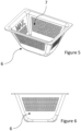
- the filter (5) has a lower wall forming the base thereof and a side wall forming the lateral surface thereof.
- the side walls of the filter (5) are composed of two parts.
- the side wall consists of a porous and permeable filter side wall upper part (7) and an impermeable filter side wall lower part (6).
- the lower wall of the filter (5) is impermeable so as not to allow liquid passage.
- the pores on the filter side wall upper part (7) are designed to be wide enough to allow fluids such as liquid detergent or softener to pass into the compartment during loading, but narrow enough to prevent solid particles or solidified residues such as powder detergent particles from filling into the compartment.
- the aim of ensuring that the lower wall of the filter (5) and the filter side wall lower part (6) are impermeable is to prevent unwanted powder detergent or solid particles from collapsing at the bottom of the filter (5), accumulating and dissolving and being transported with water.
- the impermeability of the filter side wall lower part (6) prevents or reduces the transport of unwanted solid particles into the liquid detergent compartment.
- the impermeability of the filter side wall lower part (6) also ensures that the contact of the liquid in the compartment with air is minimized without using any sealing element such as gasket, and that the chemical cleaning agents in the chamber can be stored for a longer period of time without losing their properties.
- the filter (5) structure of the present invention is a structure which supports the filling lids (8) in order to reduce the evaporation surface.
- the filter (5) of the present invention has a hollow structure. Said hollow structure allows unwanted solid particles to accumulate on the filter (5). When the user sees that there is an accumulation in this hollow area, he/she understands that cleaning is needed, removes the filter (5), cleans and puts the same back in place.
- the filter (5) is disposed just below the filling lid (8) and is positioned so as to be detached when desired.
- the filter side wall upper part (7) is in the form of a cage.
- the liquid detergent poured on the filter (5) is enabled to flow into the compartment (3, 4) by passing only through the filter side wall upper part (7) and the liquid detergent is prevented from overflowing from the filter (5) by providing sufficient flow.
- the filter side wall upper part (7) has a porous structure.
- the liquid detergent poured on the filter (5) is enabled to flow into the compartment (3, 4) by passing only through the filter side wall upper part (7) and the passage of the powder detergent into the compartment (3, 4) through the filter side wall upper part (7) is almost completely prevented.
- the loading of solid detergent into the compartment (3, 4) is prevented.
- the filter (5) completely surrounds the intake part.
- the filter (5) is positioned so as to completely seat on the intake part. Thus, it is ensured that all of the detergent poured into the intake part is filled into the filter (5) before reaching the compartment (3,4).
- the side wall extends at an angle to the vertical axis.
- the side wall extends from the lower wall towards the intake part so as to make an obtuse angle with the lower wall.
- the filter (5) has an almost truncated pyramid form.
- the permeable filter side wall upper part (7) has a height of almost twice the height of the impermeable filter side wall lower part (6).
- the filter (5) comprises warning signs.
- the filter (5) can be designed in two different colors in a distinguishable manner in order to remind the user which liquid should be filled into which compartment when the filling lid (8) of the compartment (3, 4) is open. Even if designed in the same color, a liquid detergent symbol or a softener symbol can be added on the filter (5). Warning signs may be provided on the filter (5).
Landscapes
- Engineering & Computer Science (AREA)
- Textile Engineering (AREA)
- Detail Structures Of Washing Machines And Dryers (AREA)
Abstract
Description
- The present invention relates to a washing machine comprising a detergent dispenser suitable for storing liquid cleaning agents and having an autodosing system.
- In washing machines, various chemicals are used for the purposes of cleaning or preparation for use, such as detergents and softeners, to help clean the laundry or to make the same ready for wear or use. In the state of the art washing machines, chemical cleaning agents are loaded into the compartments in the detergent dispenser by the user before washing. The dispenser is disposed in a housing called the detergent box. On the detergent box, there is a detergent box lid group which is used to deliver water onto chemicals. After the washing program starts, said chemicals are swept with water from the relevant compartment in the detergent box group where the dispenser is borne, when the control system sends the water intake command and are delivered to the tub, which is the washing environment, and onto the laundry in the drum borne so as to rotate in the tub. The laundry is cleaned with the mechanical movement obtained from the rotation of the drum and sometimes with the energy obtained by heating the water.
- Detergents are used to clean different dirt and stains while softeners are used to make the laundry soft and ready for use at the end of cleaning or to make the same smell nice. Moreover, chemical additives can be used for different purposes such as descaling, finishing and whitening.
- The users of washing machines start the washing process after adding detergent and softener to the detergent dispenser before each washing process. The user must adjust the appropriate amount of detergent and softener each time according to the type and amount of laundry. Sometimes less detergent is loaded than required, causing washing performance to be worse than expected. Sometimes excessive use of detergent results in excessive foaming, longer program duration, and unnecessary and excessive water consumption for rinsing. Additionally, there may be problems with spin-drying efficiency due to the resulting foam.
- In order to save the users from the trouble of loading the appropriate amount of chemical cleaning agents such as detergent and softener at the beginning of each washing cycle, systems called autodosing systems are developed, which enable detergent, softener or other washing agents to be placed in a compartment and to be automatically dosed by the dishwasher in the required amount when necessary. Products with or without an autodosing system are available in the market.
- In order to provide users savings in time, detergent and softener in the washing machine, it is aimed to ensure use for a long time without filling detergent and softener with the dosing system which doses the determined amount of detergent and softener in each use. There are dosing systems which can automatically adjust the dosing level according to the amount of textile to be washed by the user, the amount of dirt and the weight of the laundry. During the washing process, the dosing amount in the dishwasher is automatically determined. The use of liquid detergents and softeners is required for the operation of said system, but there is a separate compartment in the dispenser suitable for the use of powder detergents. If desired, the users can also dose powder detergent for some types of laundry. Said compartment also enables washing agents such as bleach, different types of liquid detergents than those in the dosing compartment to be delivered to the washing environment.
- The relatively new nature of autodosing systems may cause some problems for users who have been used to using products with manual detergent loading systems for years, until they learn how to use the system correctly. The users unintentionally cause various usage errors in the use of products with an autodosing system due to their old manual detergent loading habits. Although these errors seem simple, they can cause various malfunctions in the autodosing system and ultimately lead to dissatisfaction with the washing performance, detergent dosing system or products.
- In manual loading systems, the detergent or softener loaded by the user is swept from the dispenser during the water intake step of the product by means of the water pressure and flow. In washing machines with automatic dosing systems, it is required to measure and dose the required amount of said chemicals with various pump systems when necessary. Therefore, in order for the proper operation of the system, it is critical that the defined chemical is present in the defined chemical compartments, or in other words it is critical that it is loaded correctly by the user.
- For example, only liquid detergent should be loaded into the compartment defined as liquid detergent. Agents such as powder detergent, salt, descaling agent, softener, bleach etc. should never be filled into the liquid detergent compartment. If the wrong chemical is loaded, the dishwasher will not know if the correct liquid is in the dosing system, causing unwanted errors. For example, if fabric softener is loaded in the liquid detergent compartment by mistake, the washing performance will deteriorate since fabric softener will be used instead of liquid detergent during dosing.
- When detergent is loaded into the softener compartment, this time the rinsing performance will be very poor, or possibly spin-drying will not be performed due to foams.
- Therefore, it is very important that the dosing compartments are correctly marked for the suitable washing agent to be loaded so as to inform the user.
- One of the problems which can be experienced in dosing systems is that solid particles such as powder detergent, which may be accidentally placed or spilled in the dosing compartment, cause clogging in the pump, compartment and pump or areas suitable for liquid flow after the pump. If mixed with water or a liquid substance such as softener or liquid detergent, powder detergent clumps and hardens. Therefore, the contact of the powder detergent with a liquid in the dosing compartment causes serious clogging, resulting in malfunctions in the dosing system. In order to avoid such problems, a filter is usually disposed in the compartment before the check valve at the very end of the compartment or the compartment outlet structure. The task of this filter is to prevent the solid particles, especially powder detergent, which are accidentally put into the liquid compartments, from clogging the system. Said solid particles may be powder detergent, or may be particles which emerge as a result of spontaneous solidification in chemical substance packages such as liquid detergent or softener (stored with lids open, not under appropriate conditions) due to staleness. These solidifications may be partial, and while the softener is being loaded, solidified residues along with the liquid softener may be unintentionally loaded into the dosage compartment.
- In the existing autodosing systems, said filter structure is disposed in the compartment, but usually close to the outlet of the compartment. The filters have generally a flat structure and are hidden inside the dispenser compartment due to the positioning, and the existing filters cannot be seen unless the upper lid of the compartment is opened by the user. Therefore, it cannot be determined whether the filters need cleaning or not. As a result, it is not possible to make a correction before the system gives out a clogging error.
- Since the dosing lid compartment entrance is quite open, if the user accidentally loads powder detergent into said area, he/she may not realize their mistake at first. In another case, when loading powder detergent into the area reserved for the powder detergent compartment, if one of the liquid compartment lids is open, powder detergent may enter the compartment through these openings without being noticed.
- Since there are some difficulties in placing the flat filter structure in the existing products in the inlet area under the compartment lid, the filter is placed inside. For example, the dosing compartments must be closed to prevent air from getting inside as much as possible by means of the component called the compartment lid. In order to install a filter at the inlet area, it is necessary to create a design which will not cause the compartment lid to remain open. The flatness of a filter structure to be installed under the compartment lid may cause various overflow or spillage errors when filling liquid. Therefore, the pores of the filter must be small enough so as to prevent powder detergent from passing through, but large enough so as to allow the passage of liquids. The filter structures provided in the existing compartment and before the outlet are designed so as to prevent easy removal as long as the component works.
- Moreover, the filter structure must allow the cleaning of any solid particle thereon, and must collect the particles so as to prevent the same from scattering and so as not to deteriorate the operation of the filter structure. The component must not disturb the user in terms of aesthetic or ergonomic use.
- Another problem with positioning the filter so as not to be seen by the user directly relates to the performance of the product. For example, if powder detergent accidentally mixes with the softener, or if the softener mixes with the liquid detergent, said chemicals reduce the effectiveness of the other chemical. Therefore, the user may not understand why textiles are not cleaned well even though a detergent or fabric softener is used. However, if a little powder detergent mixes with the softener, the softening function is reduced. It is therefore very important to prevent accidental loading of liquid or powder particles into the compartment. The existing filter systems protect the pump and dosing system against clogging. However, the existing filter systems do not allow the product to perform other functions when the user makes an error while loading chemicals.
- In the Patent Application Document No.
KR20110004754 - Similarly, in the Patent Application Document No.
KR20100085497 -
-
Figure 1 : is the top view of the detergent box and the detergent dispenser. -
Figure 2 : is the front view of the detergent dispenser. -
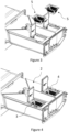
Figure 3 : is the view of the detergent dispenser where the filters are removed from the compartments. -
Figure 4 : is the view of the detergent dispenser where the filters are fitted into the compartments. -
Figure 5 : is the top of the filter. -
Figure 6 : is the sideways of the filter. -
- 1.
- Detergent box
- 2.
- Detergent dispenser
- 3.
- Detergent compartment
- 4.
- Softener compartment
- 5.
- Filter
- 6.
- Filter side wall lower part
- 7.
- Filter side wall upper part
- 8.
- Filling lid
- One of the main problems that the present invention aims to solve is not only to protect parts and components such as pumps, hoses, channels in the dosing system, as in the existing filter structures, but also to ensure that the filter is positioned in the inlet area of the chemical loading in the dosing system and to prevent from the very beginning the problems related to washing and cleaning performance which are caused by the unintentional or accidental pouring or mixing of solid particles such as powder detergent into the dosing compartment.
- One of the major problems in liquid detergent compartments is that the liquids in the compartment get into contact with air and evaporate and lose the water content and properties accordingly, solidify or deteriorate. In all of the existing dosing systems, an air gap may remain between the filler lid and the compartment due to the gaps between the moving components. Said air gap causes the chemicals in the compartment to get into contact with air. In order to prevent this, leakproofing must be provided between the filling lid and the compartment by means of a gasket structure. However, the gasket causes some difficulty in use for the user due to the requirement of additional cost and a certain force when closing or opening the lid.
- The filter system proposed in the present invention reduces the evaporation surface area of liquid detergent or softener without using any sealing element and causing ergonomic usage difficulties for the user, and can preserve the chemicals in the compartment for a longer period of time.
- Since the filter of the present invention is visible, the particles accumulated in the filter can be seen, and problems such as failure to dose or poor performance in the dishwasher can be prevented before occurring.
- The present invention relates to a washing machine comprising a detergent dispenser (2) suitable for storing liquid cleaning agents, in particular to a washing machine having an autodosing system. This type of washing machines comprise a detergent dispenser (2) having a first compartment (3) where the liquid detergent is stored and a second compartment (4) where the softener is stored; a detergent box (1) wherein the detergent dispenser (2) is placed, a tub outlet which is provided under the detergent box (1); a hydraulic pump which enables the liquids stored in the detergent dispenser (2) to be dosed and transferred into the detergent box (1); and a control valve which provides flow transmission between the detergent dispenser (2) and the hydraulic pump, which allows liquid flow from the detergent dispenser (2) to the hydraulic pump when the detergent dispenser (2) is placed in the detergent box (1) and which cuts the liquid flow from the detergent dispenser (2) to the hydraulic pump when the detergent dispenser (2) is pulled out of the detergent box (1). Moreover, there are filling lids (8) which are used to cover the compartments (3 and 4) when not loading.
- The subject-matter of the present invention is a filter (5) which prevents unwanted solid particles such as powder detergent from filling into liquid compartments by adding a filter between said filling lids (8) and the compartments (3, 4).
- The filter (5) of the present invention is positioned in the intake part of the compartments (3, 4) provided in the detergent dispenser (2), which is close to the user. Thus, when the user opens the detergent dispenser (2) by pulling the same towards himself/herself, the first part to be seen is the filter (5) structure.
- The filter (5) has a lower wall forming the base thereof and a side wall forming the lateral surface thereof. The side walls of the filter (5) are composed of two parts. The side wall consists of a porous and permeable filter side wall upper part (7) and an impermeable filter side wall lower part (6). The lower wall of the filter (5) is impermeable so as not to allow liquid passage. The pores on the filter side wall upper part (7) are designed to be wide enough to allow fluids such as liquid detergent or softener to pass into the compartment during loading, but narrow enough to prevent solid particles or solidified residues such as powder detergent particles from filling into the compartment. The aim of ensuring that the lower wall of the filter (5) and the filter side wall lower part (6) are impermeable is to prevent unwanted powder detergent or solid particles from collapsing at the bottom of the filter (5), accumulating and dissolving and being transported with water. The impermeability of the filter side wall lower part (6) prevents or reduces the transport of unwanted solid particles into the liquid detergent compartment. The impermeability of the filter side wall lower part (6) also ensures that the contact of the liquid in the compartment with air is minimized without using any sealing element such as gasket, and that the chemical cleaning agents in the chamber can be stored for a longer period of time without losing their properties. By means of the filter (5) of the present invention, the evaporation surface is reduced compared to all dosing systems which only have a filling lid in the filling opening, thus increasing the product functionality and the benefit to the user. In other words, the filter (5) structure of the present invention is a structure which supports the filling lids (8) in order to reduce the evaporation surface.
- The filter (5) of the present invention has a hollow structure. Said hollow structure allows unwanted solid particles to accumulate on the filter (5). When the user sees that there is an accumulation in this hollow area, he/she understands that cleaning is needed, removes the filter (5), cleans and puts the same back in place.
- The filter (5) is disposed just below the filling lid (8) and is positioned so as to be detached when desired.
- In an embodiment of the present invention, the filter side wall upper part (7) is in the form of a cage. Thus, the liquid detergent poured on the filter (5) is enabled to flow into the compartment (3, 4) by passing only through the filter side wall upper part (7) and the liquid detergent is prevented from overflowing from the filter (5) by providing sufficient flow.
- In another embodiment of the present invention, the filter side wall upper part (7) has a porous structure. Thus, the liquid detergent poured on the filter (5) is enabled to flow into the compartment (3, 4) by passing only through the filter side wall upper part (7) and the passage of the powder detergent into the compartment (3, 4) through the filter side wall upper part (7) is almost completely prevented. Thus, the loading of solid detergent into the compartment (3, 4) is prevented.
- In another embodiment of the present invention, the filter (5) completely surrounds the intake part. The filter (5) is positioned so as to completely seat on the intake part. Thus, it is ensured that all of the detergent poured into the intake part is filled into the filter (5) before reaching the compartment (3,4).
- In another embodiment of the present invention, the side wall extends at an angle to the vertical axis. When the filter (5) is placed in the intake opening, the side wall extends from the lower wall towards the intake part so as to make an obtuse angle with the lower wall. In a preferred version of this embodiment, the filter (5) has an almost truncated pyramid form. By means of the angled extension of the side wall, the passage of the powder detergent through the filter side wall upper part (7) becomes more difficult.
- In another embodiment of the present invention, the permeable filter side wall upper part (7) has a height of almost twice the height of the impermeable filter side wall lower part (6). Thus, when powder detergent is loaded into the filter (5), powder detergent is effectively retained by the filter (5), and when liquid detergent is filled into the filter (5), liquid detergent is allowed to flow into the compartment (3, 4) without overflowing. Thus, the filter's (5) ability to retain powder detergent and allow the passage of liquid detergent is optimized.
- In another embodiment of the present invention, the filter (5) comprises warning signs. Thus, the filter (5) can be designed in two different colors in a distinguishable manner in order to remind the user which liquid should be filled into which compartment when the filling lid (8) of the compartment (3, 4) is open. Even if designed in the same color, a liquid detergent symbol or a softener symbol can be added on the filter (5). Warning signs may be provided on the filter (5).
Claims (8)
- A washing machine comprising a detergent dispenser (2) having a first compartment (3) where the liquid detergent is stored and which has an intake part allowing the loading of liquid detergent, a second compartment (4) where the softener is stored and which has an intake part allowing the loading of softener and filling lids (8) which cover the intake parts of the first compartment (3) and the second compartment (4) and a detergent box (1) wherein the detergent dispenser (2) is placed, characterized by a plurality of filters (5) which have a hollow structure, which are positioned in a detachable manner on the intake parts of the first compartment (3) and the second compartment (4) and which have an impermeable lower wall and a side wall surrounding the lower wall and the side wall comprises an impermeable side wall lower part (6) and an at least partially permeable side wall upper part (7) .
- A washing machine as in Claim 1, characterized by the permeable filter side wall upper part (7) which is in the form of a cage.
- A washing machine as in Claim 1, characterized by the permeable filter side wall upper part (7) which has a porous form.
- A washing machine as in any of the above claims, characterized by the filter (5) which completely surrounds the intake part.
- A washing machine as in any of the above claims, characterized by the side wall which extends at an angle to the vertical axis.
- A washing machine as in Claim 5, characterized by the filter (5) which has an almost truncated pyramid form.
- A washing machine as in any of the above claims, characterized by the permeable filter side wall upper part (7) which has a height of almost twice the height of the impermeable filter side wall lower part (6).
- A washing machine as in any of the above claims, characterized by the filter (5) which comprises warning signs.
Applications Claiming Priority (1)
| Application Number | Priority Date | Filing Date | Title |
|---|---|---|---|
| TR202215961 | 2022-10-20 |
Publications (2)
| Publication Number | Publication Date |
|---|---|
| EP4357514A1 true EP4357514A1 (en) | 2024-04-24 |
| EP4357514B1 EP4357514B1 (en) | 2025-03-26 |
Family
ID=88236769
Family Applications (1)
| Application Number | Title | Priority Date | Filing Date |
|---|---|---|---|
| EP23200527.2A Active EP4357514B1 (en) | 2022-10-20 | 2023-09-28 | A washing machine comprising a detergent dispenser |
Country Status (2)
| Country | Link |
|---|---|
| EP (1) | EP4357514B1 (en) |
| PL (1) | PL4357514T3 (en) |
Citations (5)
| Publication number | Priority date | Publication date | Assignee | Title |
|---|---|---|---|---|
| CN201172752Y (en) * | 2008-04-14 | 2008-12-31 | 松下电化住宅设备机器(杭州)有限公司 | Drum-type washing machine |
| KR20100085497A (en) | 2009-01-20 | 2010-07-29 | 엘지전자 주식회사 | Filter for a liquid reservior and the liquid reservior for a clothes treating apparatus with the same |
| KR20110004754A (en) | 2009-07-08 | 2011-01-14 | 주식회사 대우일렉트로닉스 | Dual detergent input device of automatic washing machine |
| WO2018171644A1 (en) * | 2017-03-21 | 2018-09-27 | 青岛海尔滚筒洗衣机有限公司 | Device for automatically feeding detergent, and washing machine |
| JP2022000122A (en) * | 2020-06-19 | 2022-01-04 | 東芝ライフスタイル株式会社 | Washing machine |
-
2023
- 2023-09-28 PL PL23200527.2T patent/PL4357514T3/en unknown
- 2023-09-28 EP EP23200527.2A patent/EP4357514B1/en active Active
Patent Citations (5)
| Publication number | Priority date | Publication date | Assignee | Title |
|---|---|---|---|---|
| CN201172752Y (en) * | 2008-04-14 | 2008-12-31 | 松下电化住宅设备机器(杭州)有限公司 | Drum-type washing machine |
| KR20100085497A (en) | 2009-01-20 | 2010-07-29 | 엘지전자 주식회사 | Filter for a liquid reservior and the liquid reservior for a clothes treating apparatus with the same |
| KR20110004754A (en) | 2009-07-08 | 2011-01-14 | 주식회사 대우일렉트로닉스 | Dual detergent input device of automatic washing machine |
| WO2018171644A1 (en) * | 2017-03-21 | 2018-09-27 | 青岛海尔滚筒洗衣机有限公司 | Device for automatically feeding detergent, and washing machine |
| JP2022000122A (en) * | 2020-06-19 | 2022-01-04 | 東芝ライフスタイル株式会社 | Washing machine |
Also Published As
| Publication number | Publication date |
|---|---|
| PL4357514T3 (en) | 2025-07-28 |
| EP4357514B1 (en) | 2025-03-26 |
Similar Documents
| Publication | Publication Date | Title |
|---|---|---|
| EP2145041B1 (en) | Washing machine | |
| EP2147143B1 (en) | Laundry washing machine | |
| CA2561674C (en) | Bulk dispensing system for washing machine | |
| RU2544128C2 (en) | Device for washing linen | |
| JP4853562B2 (en) | Washing machine | |
| EP2142697B1 (en) | Laundry washing machine | |
| US7895864B2 (en) | Laundry additive dispenser | |
| DK3019066T3 (en) | DISHWASHER, INCLUDING A CLEANING SYSTEM FOR A LIQUID / GEL-DETERGENT DOSING UNIT AND A CONTAINER UNIT | |
| US12442123B2 (en) | Method and apparatus for cleaning laundry | |
| US20090158782A1 (en) | Methods and Systems for Water Delivery in an Additive Dispenser | |
| KR20000071652A (en) | Washing machine | |
| CA2092307C (en) | Dispenser for solid detergents | |
| TWI893289B (en) | washing machine | |
| US20130042653A1 (en) | Device for dispensing an additive in an appliance | |
| WO2008044133A1 (en) | Front-loading laundry washing machine | |
| EP4357514B1 (en) | A washing machine comprising a detergent dispenser | |
| US20170298562A1 (en) | Washing Machine Appliance with a Fluid Additive Receptacle | |
| WO2020052967A1 (en) | Method and apparatus for cleaning laundry | |
| EP3044359B1 (en) | A cleaning agent dispenser comprising an upper casing | |
| TR2022015961A2 (en) | A WASHING MACHINE WITH A DETERGENT DRAWER | |
| US9103062B2 (en) | Appliance with features for preventing additive drying | |
| EP3983602B1 (en) | A washing machine comprising a filtering member | |
| EP2239362B1 (en) | Method for the production of a drawer for the load of washing and/or rinsing products, particularly for a washing machine | |
| JP7695211B2 (en) | washing machine | |
| CN115398058B (en) | Washing machine fluid additive dispenser with multiple time delay dispensing cups |
Legal Events
| Date | Code | Title | Description |
|---|---|---|---|
| PUAI | Public reference made under article 153(3) epc to a published international application that has entered the european phase |
Free format text: ORIGINAL CODE: 0009012 |
|
| STAA | Information on the status of an ep patent application or granted ep patent |
Free format text: STATUS: REQUEST FOR EXAMINATION WAS MADE |
|
| 17P | Request for examination filed |
Effective date: 20230928 |
|
| AK | Designated contracting states |
Kind code of ref document: A1 Designated state(s): AL AT BE BG CH CY CZ DE DK EE ES FI FR GB GR HR HU IE IS IT LI LT LU LV MC ME MK MT NL NO PL PT RO RS SE SI SK SM TR |
|
| GRAP | Despatch of communication of intention to grant a patent |
Free format text: ORIGINAL CODE: EPIDOSNIGR1 |
|
| STAA | Information on the status of an ep patent application or granted ep patent |
Free format text: STATUS: GRANT OF PATENT IS INTENDED |
|
| INTG | Intention to grant announced |
Effective date: 20241210 |
|
| GRAS | Grant fee paid |
Free format text: ORIGINAL CODE: EPIDOSNIGR3 |
|
| GRAA | (expected) grant |
Free format text: ORIGINAL CODE: 0009210 |
|
| STAA | Information on the status of an ep patent application or granted ep patent |
Free format text: STATUS: THE PATENT HAS BEEN GRANTED |
|
| AK | Designated contracting states |
Kind code of ref document: B1 Designated state(s): AL AT BE BG CH CY CZ DE DK EE ES FI FR GB GR HR HU IE IS IT LI LT LU LV MC ME MK MT NL NO PL PT RO RS SE SI SK SM TR |
|
| REG | Reference to a national code |
Ref country code: GB Ref legal event code: FG4D |
|
| REG | Reference to a national code |
Ref country code: CH Ref legal event code: EP |
|
| REG | Reference to a national code |
Ref country code: DE Ref legal event code: R096 Ref document number: 602023002593 Country of ref document: DE |
|
| REG | Reference to a national code |
Ref country code: IE Ref legal event code: FG4D |
|
| PG25 | Lapsed in a contracting state [announced via postgrant information from national office to epo] |
Ref country code: RS Free format text: LAPSE BECAUSE OF FAILURE TO SUBMIT A TRANSLATION OF THE DESCRIPTION OR TO PAY THE FEE WITHIN THE PRESCRIBED TIME-LIMIT Effective date: 20250626 |
|
| PG25 | Lapsed in a contracting state [announced via postgrant information from national office to epo] |
Ref country code: FI Free format text: LAPSE BECAUSE OF FAILURE TO SUBMIT A TRANSLATION OF THE DESCRIPTION OR TO PAY THE FEE WITHIN THE PRESCRIBED TIME-LIMIT Effective date: 20250326 |
|
| REG | Reference to a national code |
Ref country code: LT Ref legal event code: MG9D |
|
| PG25 | Lapsed in a contracting state [announced via postgrant information from national office to epo] |
Ref country code: NO Free format text: LAPSE BECAUSE OF FAILURE TO SUBMIT A TRANSLATION OF THE DESCRIPTION OR TO PAY THE FEE WITHIN THE PRESCRIBED TIME-LIMIT Effective date: 20250626 |
|
| PG25 | Lapsed in a contracting state [announced via postgrant information from national office to epo] |
Ref country code: HR Free format text: LAPSE BECAUSE OF FAILURE TO SUBMIT A TRANSLATION OF THE DESCRIPTION OR TO PAY THE FEE WITHIN THE PRESCRIBED TIME-LIMIT Effective date: 20250326 |
|
| PG25 | Lapsed in a contracting state [announced via postgrant information from national office to epo] |
Ref country code: LV Free format text: LAPSE BECAUSE OF FAILURE TO SUBMIT A TRANSLATION OF THE DESCRIPTION OR TO PAY THE FEE WITHIN THE PRESCRIBED TIME-LIMIT Effective date: 20250326 |
|
| PG25 | Lapsed in a contracting state [announced via postgrant information from national office to epo] |
Ref country code: BG Free format text: LAPSE BECAUSE OF FAILURE TO SUBMIT A TRANSLATION OF THE DESCRIPTION OR TO PAY THE FEE WITHIN THE PRESCRIBED TIME-LIMIT Effective date: 20250326 Ref country code: GR Free format text: LAPSE BECAUSE OF FAILURE TO SUBMIT A TRANSLATION OF THE DESCRIPTION OR TO PAY THE FEE WITHIN THE PRESCRIBED TIME-LIMIT Effective date: 20250627 |
|
| REG | Reference to a national code |
Ref country code: NL Ref legal event code: MP Effective date: 20250326 |
|
| PG25 | Lapsed in a contracting state [announced via postgrant information from national office to epo] |
Ref country code: NL Free format text: LAPSE BECAUSE OF FAILURE TO SUBMIT A TRANSLATION OF THE DESCRIPTION OR TO PAY THE FEE WITHIN THE PRESCRIBED TIME-LIMIT Effective date: 20250326 |
|
| PG25 | Lapsed in a contracting state [announced via postgrant information from national office to epo] |
Ref country code: SE Free format text: LAPSE BECAUSE OF FAILURE TO SUBMIT A TRANSLATION OF THE DESCRIPTION OR TO PAY THE FEE WITHIN THE PRESCRIBED TIME-LIMIT Effective date: 20250326 |
|
| REG | Reference to a national code |
Ref country code: AT Ref legal event code: MK05 Ref document number: 1779073 Country of ref document: AT Kind code of ref document: T Effective date: 20250326 |
|
| PG25 | Lapsed in a contracting state [announced via postgrant information from national office to epo] |
Ref country code: SM Free format text: LAPSE BECAUSE OF FAILURE TO SUBMIT A TRANSLATION OF THE DESCRIPTION OR TO PAY THE FEE WITHIN THE PRESCRIBED TIME-LIMIT Effective date: 20250326 |
|
| PG25 | Lapsed in a contracting state [announced via postgrant information from national office to epo] |
Ref country code: PT Free format text: LAPSE BECAUSE OF FAILURE TO SUBMIT A TRANSLATION OF THE DESCRIPTION OR TO PAY THE FEE WITHIN THE PRESCRIBED TIME-LIMIT Effective date: 20250728 Ref country code: ES Free format text: LAPSE BECAUSE OF FAILURE TO SUBMIT A TRANSLATION OF THE DESCRIPTION OR TO PAY THE FEE WITHIN THE PRESCRIBED TIME-LIMIT Effective date: 20250326 |
|
| PGFP | Annual fee paid to national office [announced via postgrant information from national office to epo] |
Ref country code: DE Payment date: 20250919 Year of fee payment: 3 |
|
| PG25 | Lapsed in a contracting state [announced via postgrant information from national office to epo] |
Ref country code: IT Free format text: LAPSE BECAUSE OF FAILURE TO SUBMIT A TRANSLATION OF THE DESCRIPTION OR TO PAY THE FEE WITHIN THE PRESCRIBED TIME-LIMIT Effective date: 20250326 |
|
| PGFP | Annual fee paid to national office [announced via postgrant information from national office to epo] |
Ref country code: PL Payment date: 20250923 Year of fee payment: 3 Ref country code: TR Payment date: 20250919 Year of fee payment: 3 |
|
| PG25 | Lapsed in a contracting state [announced via postgrant information from national office to epo] |
Ref country code: AT Free format text: LAPSE BECAUSE OF FAILURE TO SUBMIT A TRANSLATION OF THE DESCRIPTION OR TO PAY THE FEE WITHIN THE PRESCRIBED TIME-LIMIT Effective date: 20250326 |
|
| PG25 | Lapsed in a contracting state [announced via postgrant information from national office to epo] |
Ref country code: EE Free format text: LAPSE BECAUSE OF FAILURE TO SUBMIT A TRANSLATION OF THE DESCRIPTION OR TO PAY THE FEE WITHIN THE PRESCRIBED TIME-LIMIT Effective date: 20250326 |
|
| PG25 | Lapsed in a contracting state [announced via postgrant information from national office to epo] |
Ref country code: RO Free format text: LAPSE BECAUSE OF FAILURE TO SUBMIT A TRANSLATION OF THE DESCRIPTION OR TO PAY THE FEE WITHIN THE PRESCRIBED TIME-LIMIT Effective date: 20250326 |
|
| PG25 | Lapsed in a contracting state [announced via postgrant information from national office to epo] |
Ref country code: SK Free format text: LAPSE BECAUSE OF FAILURE TO SUBMIT A TRANSLATION OF THE DESCRIPTION OR TO PAY THE FEE WITHIN THE PRESCRIBED TIME-LIMIT Effective date: 20250326 |
|
| PG25 | Lapsed in a contracting state [announced via postgrant information from national office to epo] |
Ref country code: IS Free format text: LAPSE BECAUSE OF FAILURE TO SUBMIT A TRANSLATION OF THE DESCRIPTION OR TO PAY THE FEE WITHIN THE PRESCRIBED TIME-LIMIT Effective date: 20250726 |
|
| REG | Reference to a national code |
Ref country code: DE Ref legal event code: R097 Ref document number: 602023002593 Country of ref document: DE |
|
| PG25 | Lapsed in a contracting state [announced via postgrant information from national office to epo] |
Ref country code: DK Free format text: LAPSE BECAUSE OF FAILURE TO SUBMIT A TRANSLATION OF THE DESCRIPTION OR TO PAY THE FEE WITHIN THE PRESCRIBED TIME-LIMIT Effective date: 20250326 |
|
| PG25 | Lapsed in a contracting state [announced via postgrant information from national office to epo] |
Ref country code: CZ Free format text: LAPSE BECAUSE OF FAILURE TO SUBMIT A TRANSLATION OF THE DESCRIPTION OR TO PAY THE FEE WITHIN THE PRESCRIBED TIME-LIMIT Effective date: 20250326 |
|
| PLBE | No opposition filed within time limit |
Free format text: ORIGINAL CODE: 0009261 |
|
| STAA | Information on the status of an ep patent application or granted ep patent |
Free format text: STATUS: NO OPPOSITION FILED WITHIN TIME LIMIT |
|
| REG | Reference to a national code |
Ref country code: CH Ref legal event code: L10 Free format text: ST27 STATUS EVENT CODE: U-0-0-L10-L00 (AS PROVIDED BY THE NATIONAL OFFICE) Effective date: 20260211 |
|
| 26N | No opposition filed |
Effective date: 20260105 |
|
| PG25 | Lapsed in a contracting state [announced via postgrant information from national office to epo] |
Ref country code: LU Free format text: LAPSE BECAUSE OF NON-PAYMENT OF DUE FEES Effective date: 20250928 |
|
| REG | Reference to a national code |
Ref country code: BE Ref legal event code: MM Effective date: 20250930 |
|
| PG25 | Lapsed in a contracting state [announced via postgrant information from national office to epo] |
Ref country code: LT Free format text: LAPSE BECAUSE OF FAILURE TO SUBMIT A TRANSLATION OF THE DESCRIPTION OR TO PAY THE FEE WITHIN THE PRESCRIBED TIME-LIMIT Effective date: 20250326 |
|
| PG25 | Lapsed in a contracting state [announced via postgrant information from national office to epo] |
Ref country code: MC Free format text: LAPSE BECAUSE OF FAILURE TO SUBMIT A TRANSLATION OF THE DESCRIPTION OR TO PAY THE FEE WITHIN THE PRESCRIBED TIME-LIMIT Effective date: 20250326 |
|
| PG25 | Lapsed in a contracting state [announced via postgrant information from national office to epo] |
Ref country code: IE Free format text: LAPSE BECAUSE OF NON-PAYMENT OF DUE FEES Effective date: 20250928 Ref country code: BE Free format text: LAPSE BECAUSE OF NON-PAYMENT OF DUE FEES Effective date: 20250930 |
|
| PG25 | Lapsed in a contracting state [announced via postgrant information from national office to epo] |
Ref country code: FR Free format text: LAPSE BECAUSE OF NON-PAYMENT OF DUE FEES Effective date: 20250930 |