EP4357240A1 - An airfoil profile for an aircraft and aerodynamic surfaces using said airfoil profile - Google Patents
An airfoil profile for an aircraft and aerodynamic surfaces using said airfoil profile Download PDFInfo
- Publication number
- EP4357240A1 EP4357240A1 EP22202663.5A EP22202663A EP4357240A1 EP 4357240 A1 EP4357240 A1 EP 4357240A1 EP 22202663 A EP22202663 A EP 22202663A EP 4357240 A1 EP4357240 A1 EP 4357240A1
- Authority
- EP
- European Patent Office
- Prior art keywords
- airfoil
- chord length
- along
- edge portion
- chordwise direction
- Prior art date
- Legal status (The legal status is an assumption and is not a legal conclusion. Google has not performed a legal analysis and makes no representation as to the accuracy of the status listed.)
- Granted
Links
Images


Classifications
-
- B—PERFORMING OPERATIONS; TRANSPORTING
- B64—AIRCRAFT; AVIATION; COSMONAUTICS
- B64U—UNMANNED AERIAL VEHICLES [UAV]; EQUIPMENT THEREFOR
- B64U20/00—Constructional aspects of UAVs
- B64U20/20—Constructional aspects of UAVs for noise reduction
-
- B—PERFORMING OPERATIONS; TRANSPORTING
- B64—AIRCRAFT; AVIATION; COSMONAUTICS
- B64C—AEROPLANES; HELICOPTERS
- B64C11/00—Propellers, e.g. of ducted type; Features common to propellers and rotors for rotorcraft
- B64C11/16—Blades
- B64C11/18—Aerodynamic features
-
- B—PERFORMING OPERATIONS; TRANSPORTING
- B64—AIRCRAFT; AVIATION; COSMONAUTICS
- B64U—UNMANNED AERIAL VEHICLES [UAV]; EQUIPMENT THEREFOR
- B64U30/00—Means for producing lift; Empennages; Arrangements thereof
- B64U30/10—Wings
-
- B—PERFORMING OPERATIONS; TRANSPORTING
- B64—AIRCRAFT; AVIATION; COSMONAUTICS
- B64C—AEROPLANES; HELICOPTERS
- B64C11/00—Propellers, e.g. of ducted type; Features common to propellers and rotors for rotorcraft
- B64C11/16—Blades
- B64C11/20—Constructional features
-
- B—PERFORMING OPERATIONS; TRANSPORTING
- B64—AIRCRAFT; AVIATION; COSMONAUTICS
- B64C—AEROPLANES; HELICOPTERS
- B64C3/00—Wings
- B64C3/10—Shape of wings
- B64C3/14—Aerofoil profile
-
- B—PERFORMING OPERATIONS; TRANSPORTING
- B64—AIRCRAFT; AVIATION; COSMONAUTICS
- B64C—AEROPLANES; HELICOPTERS
- B64C3/00—Wings
- B64C3/36—Structures adapted to reduce effects of aerodynamic or other external heating
-
- B—PERFORMING OPERATIONS; TRANSPORTING
- B64—AIRCRAFT; AVIATION; COSMONAUTICS
- B64U—UNMANNED AERIAL VEHICLES [UAV]; EQUIPMENT THEREFOR
- B64U10/00—Type of UAV
- B64U10/25—Fixed-wing aircraft
-
- B—PERFORMING OPERATIONS; TRANSPORTING
- B64—AIRCRAFT; AVIATION; COSMONAUTICS
- B64U—UNMANNED AERIAL VEHICLES [UAV]; EQUIPMENT THEREFOR
- B64U30/00—Means for producing lift; Empennages; Arrangements thereof
- B64U30/20—Rotors; Rotor supports
-
- B—PERFORMING OPERATIONS; TRANSPORTING
- B64—AIRCRAFT; AVIATION; COSMONAUTICS
- B64U—UNMANNED AERIAL VEHICLES [UAV]; EQUIPMENT THEREFOR
- B64U30/00—Means for producing lift; Empennages; Arrangements thereof
- B64U30/20—Rotors; Rotor supports
- B64U30/21—Rotary wings
Definitions
- the invention relates to an airfoil profile.
- the invention further relates to a wing or propeller blade having such an airfoil profile.
- the invention further relates to an aircraft equipped with said wing or propeller blade.
- the invention provides an airfoil profile for an aircraft, such as an unmanned aerial system, the airfoil profile being configured for reducing a noise level, the airfoil profile comprising:
- the airfoil centroid is arranged from 43 % to 55 %, preferably from 45 % to 54 %, of the chord length along the chordwise direction.
- the upper and lower airfoil surfaces are shaped such that the pressure center of the lifting force is arranged from 40 % to 60 %, preferably from 43 % to 55 %, more preferably from 45 % to 54 %, of the chord length along the chordwise direction.
- the upper airfoil surface comprises a first upper curved portion that is arranged between the leading edge portion and the airfoil centroid along the chordwise direction, preferably from 20 % to 30 % of the chord length, more preferably from 20 % to 25 % of the chord length, more preferably from 21 % to 23 % of the chord length.
- the first upper curved portion has a maximum modulus of the radius of curvature from 1.8 times to 4.4 times the chord length, wherein preferably the maximum modulus of the radius of curvature continuously decreases from an airfoil outward portion towards an airfoil inward portion along a spanwise direction.
- the location of the first upper curved portion along the chordwise direction is measured from the location of the maximum modulus of the radius of curvature.
- the spatial extension of the first upper curved portion along the chordwise direction is measured as the full-width at half-maximum (FWHM) of the radius of curvature.
- the spatial extension of the first upper curved portion along the chordwise direction is from 15 percentage points to 22 percentage points.
- the spatial extension of the first upper curved portion along the chordwise direction continuosly increases from an airfoil outward portion towards an airfoil inward portion along a spanwise direction.
- the upper airfoil surface comprises a second upper curved portion that is arranged between the airfoil centroid and the trailing edge portion along the chordwise direction, preferably from 75 % to 85 % of the chord length, more preferably from 78 % to 82 % of the chord length, more preferably from 79 % to 80 % of the chord length.
- the location of the second upper curved portion along the chordwise direction is measured from the location of the maximum modulus of the radius of curvature.
- the spatial extension of the second upper curved portion along the chordwise direction is measured as the full-width at half-maximum (FWHM) of the radius of curvature.
- the spatial extension of the second upper curved portion along the chordwise direction is from 19 percentage points to 26 percentage points.
- the spatial extension of the second upper curved portion along the chordwise direction continuosly decreases from an airfoil outward portion towards an airfoil inward portion along a spanwise direction.
- the second upper curved portion has a maximum modulus of the radius of curvature from 1.9 times to 2.1 times the chord length, wherein preferably the maximum modulus of the radius of curvature continuously increases from an airfoil outward portion towards an airfoil inward portion along a spanwise direction.
- the upper airfoil surface comprises a third upper curved portion that is arranged between the leading edge portion and the trailing edge portion along the chordwise direction, preferably from 45 % to 55 % of the chord length, more preferably from 49 % to 53 % of the chord length, more preferably from 50 % to 52 % of the chord length.
- the location of the third upper curved portion along the chordwise direction is measured from the location of the minimum modulus of the radius of curvature.
- the spatial extension of the third upper curved portion along the chordwise direction is measured as the full-width at double-minimum (FWDM) of the radius of curvature.
- the spatial extension of the third upper curved portion along the chordwise direction is from 36 percentage points to 40 percentage points.
- the spatial extension of the third upper curved portion along the chordwise direction continuosly decreases from an airfoil outward portion towards an airfoil inward portion along a spanwise direction.
- the third upper curved portion has a maximum modulus of the radius of curvature from 0.5 times to 0.8 times the chord length, wherein preferably the minimum modulus of the radius of curvature continuously decreases from an airfoil outward portion towards an airfoil inward portion along a spanwise direction.
- the lower airfoil surface comprises a first lower flat portion that is arranged between the leading edge portion and the airfoil centroid along the chordwise direction, preferably from 25 % to 30 % of the chord length, more preferably from 25 % to 29 % of the chord length, more preferably from 25.5 % to 28.8 % of the chord length.
- the first lower flat portion has a maximum modulus of the radius of curvature above 10 times the chord length.
- the location of the first lower flat portion along the chordwise direction is measured from location of a first zero crossing of a second derivative of the lower airfoil surface that is closest to the leading edge portion.
- the spatial extension of the first lower flat portion along the chordwise direction is measured as the full-width at the radius of curvature being 10 times the chord length.
- the spatial extension of the first lower flat portion along the chordwise direction is from 8 percentage points to 30 percentage points.
- the spatial extension of the first lower flat portion along the chordwise direction continuosly increases from an airfoil outward portion towards an airfoil inward portion along a spanwise direction.
- the lower airfoil surface comprises a second lower flat portion that is arranged between the leading edge portion and the trailing edge portion along the chordwise direction, preferably from 35 % to 55 % of the chord length, more preferably from 36 % to 52 % of the chord length.
- the location of the second lower flat portion along the chordwise direction is measured from the location a second zero crossing of a second derivative of the lower airfoil surface that is closest to the trailing edge portion.
- the spatial extension of the second lower flat portion along the chordwise direction is measured as the full-width at the radius of curvature being 10 times the chord length.
- the spatial extension of the second upper curved portion along the chordwise direction is from 1 percentage points to 3 percentage points.
- the spatial extension of the second lower flat portion along the chordwise direction continuosly decreases from an airfoil outward portion towards an airfoil inward portion along a spanwise direction.
- the lower airfoil surface comprises a lower curved portion that is arranged between the airfoil centroid and the trailing edge portion along the chordwise direction, preferably from 70 % to 80 % of the chord length, more preferably from 75 % to 79 % of the chord length, more preferably from 77 % to 78 % of the chord length.
- the location of the lower curved portion along the chordwise direction is measured from the location of the minimum modulus of the radius of curvature.
- the spatial extension of the lower curved portion along the chordwise direction is measured as the full-width at double-minimum (FWDM) of the radius of curvature.
- the spatial extension of the lower curved portion along the chordwise direction is from 23 percentage points to 45 percentage points.
- the spatial extension of the lower curved portion along the chordwise direction continuosly decreases from an airfoil outward portion towards an airfoil inward portion along a spanwise direction.
- the lower curved portion has a maximum modulus of the radius of curvature from 0.85 times to 1.35 times the chord length, wherein preferably the minimum modulus of the radius of curvature continuously decreases from an airfoil outward portion towards an airfoil inward portion along a spanwise direction.
- the invention provides a wing or a propeller blade for an aircraft comprising a preferred airfoil profile.
- the invention provides a propeller for an aircraft comprising a hub and at least one preferred propeller blade that is supported by the hub.
- the invention provides an aircraft, preferably an unmanned aerial system, comprising a preferred wing, propeller blade and/or propeller.
- the invention is based on the idea of a new airfoil type that is able - due to its form - to twist a wing or propeller blade in such a way that no mechanism for varying the pitch is necessary.
- a prerequisite may include an amorph structure of one material or a material that has the same structural characteristics in all directions.
- the airfoil shape similar to a mal dolphin body is producing a lift force when inserted in a lifting surface that not only bends but also twists the airfoil under aerodynamic load (similar to aerodynamic tailoring).
- the position of the pressure center (Cp) is around 25% along the chord length from the leading edge.
- the Cp is the application point of the lift and drag forces generated by the airfoil.
- a realistic wing under aerodynamic forces usually exhibits a flow that is not only laminar but inlcudes also areas where turbulence occurs.
- One source of vortices and pressure drops are wing/blade tip vortices.
- the vortex distribution can be complex and interactions between those may also produce acoustic vibrations (noise).
- the leading edge thereof can be bent and twisted under the aerodynamic forces; typically as a pitch-up effect, i.e. the leading edge rises under aerodynamic forces.
- the airflow may also have a laminar separation over the top side of the airfoil where subsequently the airflow may then reattach. This is another source of vortices/recirculation and therefore potential noise. After reattaching of the airflow on the top side, at the trailing edge, there is again a potential for separation which again may produce noise effects.
- wing design and manufacturing overcome the twisting effect. If the wing is too flexible around its elastic axis, it is able to pitch down and a reversal of the effect on the airflow is that it reattaches over the top side but separates from the bottom side. As a result flutter can occur. For this reason typically the main spars of the structure are preferably positioned either on the elastic axis or behind of it towards trailing edge.
- wingbox - D-box a closed wing structure
- CFRP carbon fiber reinforced plastic
- the propeller are usually manufactured from plastic (e.g. by injection moulding), CFRP layup or sometimens even wood.
- the idea is based on a new airfoil type that can overcome the deficiencies by shaping the airfoil in such a way that laminar separation bubbles and premature separation on the trailing edge is reduced, delayed, or even prevented.
- the airfoil is shaped such that the pressure center (Cp) as the application point for the lifting/normal force is closer towards the trailing edge and the elastic axis is kept forwardback.
- the aerodynamic load generates a torque on the airfoil that causes its leading edge to pitch down (pitch-down effect) around the elastic axis.
- the airfoil may operate at a lower angle of attack or keep a quasi-constant operating angle of attack.
- the bending of the blade/wing will also twist it without any extra means, such as a pitch control mechanism.
- the airfoil performance factor - defined as lift coefficient divided by drag coefficient - is used as the key point for comparison.
- a digital wind tunnel simulation shows that at 5° deg AoA the airflow is mainly laminar over the profile. The positive effect is no fluctuation appears and the production of noise is reduced or eliminated.
- the zone B (at the trailing edge) separation is normal for every airfoil at Reynolds numbers (Re) below 1 milion.
- Reynolds numbers Re
- propellers for drones operate at a maximum of Re 500.000.
- the shape of the airfoil causes the the lift force to apply on the center of pressure so as to create a momentum around the airfoil centroid, i.e. the elastic axis. If this force is acting forward of elastic axis, as is typical in conventional airfoils, a pitch up momentum is generated.
- the shape of the airfoil causes the lift force to apply behind the elastic axis, such that a pitch down momentum is produced. Up to an AoA of about 6° the pitch down effect works to reduce the AoA. At about 6° of AoA the lift force applies at the elastic axis thereby causing pure bending of the airfoil without torsion.
- the airfoil family used for a propeller blade comprises thickness, thickness position as well as camber modification in the following spectrum:
- the requirement of stability of the maximum performance vs. AoA is even stronger for an application where the incoming airflow is varing through different flight phases.
- the incident flow has a low incidence up to negative angles.
- the airfoil disclosed herein is capable of pitching the blade by varying the rotational speed of the propeller.
- the aircraft 10 is configured as an unmanned aerial system (UAS) 11.
- the UAS 11 comprises a UAS body 12 to which a pair of wings 13 is attached.
- the UAS 11 has a plurality of control surfaces 14 that are arranged in manner known per se.
- the UAS 11 further comprises a propeller 20 for propulsion.
- the propeller 20 comprises a hub 21 which supports a plurality of propeller blades 22.
- a the propeller blade 22 has an airfoil profile 30.
- the airfoil profile 30 corresponds to a cross-section through the propeller blade 22 along plane II-II.
- the airfoil profile 30 is viewed along a spanwise direction from the tip of the propeller blade 22 towards the root of the propeller blade 22 that is supported by the hub 21.
- the spanwise direction therefore corresponds to a direction orthogonal to the drawing plane of Fig. 2 .
- the airfoil profile 30 comprises a leading edge portion 31 and a trailing edge portion 32.
- the leading edge portion 31 and the trailing edge portion 32 are spaced apart along a chordwise direction.
- the chordwise direction lies in the drawing plane of Fig. 2 .
- the chordwise direction and the spanwise direction define a vertical direction, that is orthogonal to both the chordwise and the spanwise direction. In other words the chordwise, spanwise and vertical directions are mutually orthogonal to each other.
- the airfoil profile 30 comprises an airfoil centroid 33.
- the airfoil centroid 33 is also called elastic axis.
- the airfoil centroid 33 extends in the spanwise direction.
- the airfoil centroid 33 is influenced by the shape of the airfoil profile 30 which is subsequently described in more detail.
- the airfoil profile 30 comprises an upper airfoil surface 40.
- the upper airfoil surface 40 extends between the leading edge portion 31 and the trailing edge portion 32.
- the upper airfoil surface 40 lies within a tolerance band of ⁇ 5 %, preferably ⁇ 3 %, more prefably ⁇ 1 %, most preferably ⁇ 0.3% from the polynomial of equation (1).
- the upper airfoil surface 40 comprises a first upper curved portion 41.
- the first upper curved portion 41 has a maximum modulus of the radius of curvature (see equation (2)) from from 1.8 times to 4.4 times of the chord length depending on the thickness. When viewed along the spanwise direction, the maximum modulus of the radius of curvature continuously decreases.
- the maximum modulus of the radius of curvature for the first upper curved portion 41 is located between the leading edge portion 31 and the airfoil centroid 33 along the chordwise direction. This maximum is preferably located from 21 % to 23 % of the chord length.
- the first upper curved portion 41 has a spatial extension along the chordwise direction that is measured as the full-width at half-maximum (FWHM) of the radius of curvature. With the previously selected coefficients, the spatial extension of the first upper curved portion 41 along the chordwise direction is in the range of 15 percentage points to 22 percentage points. When viewed along the spanwise direction, the spatial extension of the first upper curved portion 41 continuously increases.
- FWHM full-width at half-maximum
- the upper airfoil surface 40 comprises a second upper curved portion 42.
- the second upper curved portion 42 has a maximum modulus of the radius of curvature (see equation (2)) from from 1.9 times to 2.1 times of the chord length depending on the thickness. When viewed along the spanwise direction, the maximum modulus of the radius of curvature continuously increases.
- the maximum modulus of the radius of curvature for the second upper curved portion 42 is located between the trailing edge portion 32 and the airfoil centroid 33 along the chordwise direction. This maximum is preferably located from 79 % to 80 % of the chord length.
- the second upper curved portion 42 has a spatial extension along the chordwise direction that is measured as the full-width at half-maximum (FWHM) of the radius of curvature. With the previously selected coefficients, the spatial extension of the second upper curved portion 42 along the chordwise direction is in the range of 19 percentage points to 26 percentage points. When viewed along the spanwise direction, the spatial extension of the second upper curved portion 42 continuously decreases.
- FWHM full-width at half-maximum
- the upper airfoil surface 40 comprises a third upper curved portion 43.
- the third upper curved portion 43 has a minimum modulus of the radius of curvature (see equation (2)) from from 0.5 times to 0.8 times of the chord length depending on the thickness. When viewed along the spanwise direction, the maximum modulus of the radius of curvature continuously decreases.
- the minimum modulus of the radius of curvature for the third upper curved portion 43 is located between the leading edge portion 31 and the trailing edge portion 32 along the chordwise direction. This minimum is preferably located from 50 % to 52 % of the chord length.
- the third upper curved portion 43 has a spatial extension along the chordwise direction that is measured as the full-width at double-minimum (FWDM) of the radius of curvature. With the previously selected coefficients, the spatial extension of the third upper curved portion 43 along the chordwise direction is in the range of 36 percentage points to 40 percentage points. When viewed along the spanwise direction, the spatial extension of the third upper curved portion 43 continuously decreases.
- FWDM full-width at double-minimum
- the airfoil profile 30 comprises a lower airfoil surface 50.
- the lower airfoil surface 50 extends between the leading edge portion 31 and the trailing edge portion 32.
- z has at least one zero at one point along the chord length.
- a portion that has a radius of curvature larger than 10 times the chord length is deemed to be flat.
- the lower airfoil surface 50 comprises a first lower flat portion 51.
- the first lower flat portion 51 exceeds modulus of the radius of curvature (see equation (4)) of 10.
- the first lower flat portion 51 is located between the leading edge portion 31 and the airfoil centroid 33 along the chordwise direction.
- the location can be defined by the first zero of z" from the leading edge portion 31, i.e. the zero closest to the leading edge portion 31.
- the zero is preferably located from 25 % to 30 % of the chord length, more preferably from 25 % to 29 % of the chord length, more preferably from 25.5 % to 28.8 % of the chord length.
- the first lower flat portion 51 has a spatial extension along the chordwise direction that is measured as the full-width at a radius of curvature of 10 (FW@R10). With the previously selected coefficients, the spatial extension of the first lower flat portion 51 along the chordwise direction is in the range of 8 percentage points to 30 percentage points. When viewed along the spanwise direction, the spatial extension of the first lower flat portion 51 continuously increases.
- the lower airfoil surface 50 comprises a second lower flat portion 52.
- the second lower flat portion 52 exceeds modulus of the radius of curvature (see equation (4)) of 10.
- the second lower flat portion 52 is located between the leading edge portion 31 and the trailing edge portion 32 along the chordwise direction. The location can be defined by the last zero of z" from the leading edge portion 31, i.e. the zero closest to the trailing edge portion 32. The zero is preferably located from 36 % to 52 % of the chord length.
- the second lower flat portion 52 has a spatial extension along the chordwise direction that is measured as the full-width at a radius of curvature of 10 (FW@R10). With the previously selected coefficients, the spatial extension of the second lower flat portion 52 along the chordwise direction is in the range of 1 percentage points to 3 percentage points. When viewed along the spanwise direction, the spatial extension of the second lower flat portion 52 continuously decreases.
- the lower airfoil surface 50 comprises a lower curved portion 53.
- the lower curved portion 53 has a minimum modulus of the radius of curvature (see equation (4)) from 0.85 times to 1.35 times of the chord length depending on the thickness. When viewed along the spanwise direction, the maximum modulus of the radius of curvature continuously decreases.
- the minimum modulus of the radius of curvature for the lower curved portion 53 is located between the trailing edge portion 32 and the airfoil centroid 33 along the chordwise direction. This minimum is preferably located from 75 % to 79 % of the chord length, more preferably from 77 % to 78 % of the chord length.
- the lower curved portion 53 has a spatial extension along the chordwise direction that is measured as the full-width at double-minimum (FWDM) of the radius of curvature. With the previously selected coefficients, the spatial extension of the lower curved portion 53 along the chordwise direction is in the range of 23 percentage points to 45 percentage points. When viewed along the spanwise direction, the spatial extension of the lower curved portion 53 continuously decreases.
- FWDM full-width at double-minimum
- the airfoil profile (30) for an aircraft (10), such as an unmanned aerial system (11).
- the airfoil profile (30) comprises a leading edge portion (31) and a trailing edge portion (32) that are spaced apart along a chordwise direction, an airfoil centroid (33); and an upper airfoil surface (40) and a lower airfoil surface (50).
- the airfoil surfaces (40, 50) are shaped such that the pressure center (Cp) of the lifting force is arranged at the same chord location as the airfoil centroid (33) or closer to the trailing edge portion (32) along the chordwise direction than the airfoil centroid (33). With this, a pitch-down momentum is generated that urges the leading edge portion (31) towards a lower angle of attack (AoA).
Landscapes
- Engineering & Computer Science (AREA)
- Aviation & Aerospace Engineering (AREA)
- Mechanical Engineering (AREA)
- Physics & Mathematics (AREA)
- Fluid Mechanics (AREA)
- Remote Sensing (AREA)
- Structures Of Non-Positive Displacement Pumps (AREA)
Abstract
Description
- The invention relates to an airfoil profile. The invention further relates to a wing or propeller blade having such an airfoil profile. The invention further relates to an aircraft equipped with said wing or propeller blade.
- The development of modern aircraft, such as drones (Unmaned Aerial Vehicles) or aerial mobility concepts, are increasingly concentrating on environmental impact. A key factor for their acceptance to the wide masses of publicum and certification requirements is to keep the noise level as low as possible. When it gets to EASA noise level requirements reference is made to ICAO Annex 16, Volume I. Every National Aviation Authority is issuing noise level standards using EASA Form 45 (for aircraft - fixed wing and rotorcrafts). There are many ways to reduce the noise produced by the aircraft but not all are suitable to be implemented in UASs. An important source of noise are the propulsion elements and the propeller(s). A variable pitch propeller is typically used on civil and military aviation. However, for drones this is not always feasable due to weight limitation.
- It is the object of the invention to reduce noise emanating from an airfoil. The object is achieved by the subject-matter of the independent claims. Preferred embodiments are subject-matter of the dependent claims.
- The invention provides an airfoil profile for an aircraft, such as an unmanned aerial system, the airfoil profile being configured for reducing a noise level, the airfoil profile comprising:
- a leading edge portion and a trailing edge portion that are spaced apart along a chordwise direction;
- an airfoil centroid that is arranged from 40 % to 60 % of a chord length along the chordwise direction; and
- an upper airfoil surface and a lower airfoil surface that are shaped so as to generate a lifting force in a manner such that a pressure center of the lifting force is arranged at the same chord location as the airfoil centroid or closer to the trailing edge portion along the chordwise direction than the airfoil centroid.
- Preferably, the airfoil centroid is arranged from 43 % to 55 %, preferably from 45 % to 54 %, of the chord length along the chordwise direction.
- Preferably, the upper and lower airfoil surfaces are shaped such that the pressure center of the lifting force is arranged from 40 % to 60 %, preferably from 43 % to 55 %, more preferably from 45 % to 54 %, of the chord length along the chordwise direction.
- Preferably, the upper airfoil surface comprises a first upper curved portion that is arranged between the leading edge portion and the airfoil centroid along the chordwise direction, preferably from 20 % to 30 % of the chord length, more preferably from 20 % to 25 % of the chord length, more preferably from 21 % to 23 % of the chord length.
- Preferably, the first upper curved portion has a maximum modulus of the radius of curvature from 1.8 times to 4.4 times the chord length, wherein preferably the maximum modulus of the radius of curvature continuously decreases from an airfoil outward portion towards an airfoil inward portion along a spanwise direction.
- Preferably, the location of the first upper curved portion along the chordwise direction is measured from the location of the maximum modulus of the radius of curvature.
- Preferably, the spatial extension of the first upper curved portion along the chordwise direction is measured as the full-width at half-maximum (FWHM) of the radius of curvature.
- Preferably, the spatial extension of the first upper curved portion along the chordwise direction is from 15 percentage points to 22 percentage points.
- Preferably, the spatial extension of the first upper curved portion along the chordwise direction continuosly increases from an airfoil outward portion towards an airfoil inward portion along a spanwise direction.
- Preferably, the upper airfoil surface comprises a second upper curved portion that is arranged between the airfoil centroid and the trailing edge portion along the chordwise direction, preferably from 75 % to 85 % of the chord length, more preferably from 78 % to 82 % of the chord length, more preferably from 79 % to 80 % of the chord length.
- Preferably, the location of the second upper curved portion along the chordwise direction is measured from the location of the maximum modulus of the radius of curvature.
- Preferably, the spatial extension of the second upper curved portion along the chordwise direction is measured as the full-width at half-maximum (FWHM) of the radius of curvature.
- Preferably, the spatial extension of the second upper curved portion along the chordwise direction is from 19 percentage points to 26 percentage points.
- Preferably, the spatial extension of the second upper curved portion along the chordwise direction continuosly decreases from an airfoil outward portion towards an airfoil inward portion along a spanwise direction.
- Preferably, the second upper curved portion has a maximum modulus of the radius of curvature from 1.9 times to 2.1 times the chord length, wherein preferably the maximum modulus of the radius of curvature continuously increases from an airfoil outward portion towards an airfoil inward portion along a spanwise direction.
- Preferably, the upper airfoil surface comprises a third upper curved portion that is arranged between the leading edge portion and the trailing edge portion along the chordwise direction, preferably from 45 % to 55 % of the chord length, more preferably from 49 % to 53 % of the chord length, more preferably from 50 % to 52 % of the chord length.
- Preferably, the location of the third upper curved portion along the chordwise direction is measured from the location of the minimum modulus of the radius of curvature.
- Preferably, the spatial extension of the third upper curved portion along the chordwise direction is measured as the full-width at double-minimum (FWDM) of the radius of curvature.
- Preferably, the spatial extension of the third upper curved portion along the chordwise direction is from 36 percentage points to 40 percentage points.
- Preferably, the spatial extension of the third upper curved portion along the chordwise direction continuosly decreases from an airfoil outward portion towards an airfoil inward portion along a spanwise direction.
- Preferably, the third upper curved portion has a maximum modulus of the radius of curvature from 0.5 times to 0.8 times the chord length, wherein preferably the minimum modulus of the radius of curvature continuously decreases from an airfoil outward portion towards an airfoil inward portion along a spanwise direction.
- Preferably, the lower airfoil surface comprises a first lower flat portion that is arranged between the leading edge portion and the airfoil centroid along the chordwise direction, preferably from 25 % to 30 % of the chord length, more preferably from 25 % to 29 % of the chord length, more preferably from 25.5 % to 28.8 % of the chord length.
- Preferably the first lower flat portion has a maximum modulus of the radius of curvature above 10 times the chord length.
- Preferably, the location of the first lower flat portion along the chordwise direction is measured from location of a first zero crossing of a second derivative of the lower airfoil surface that is closest to the leading edge portion.
- Preferably, the spatial extension of the first lower flat portion along the chordwise direction is measured as the full-width at the radius of curvature being 10 times the chord length.
- Preferably, the spatial extension of the first lower flat portion along the chordwise direction is from 8 percentage points to 30 percentage points.
- Preferably, the spatial extension of the first lower flat portion along the chordwise direction continuosly increases from an airfoil outward portion towards an airfoil inward portion along a spanwise direction.
- Preferably, the lower airfoil surface comprises a second lower flat portion that is arranged between the leading edge portion and the trailing edge portion along the chordwise direction, preferably from 35 % to 55 % of the chord length, more preferably from 36 % to 52 % of the chord length.
- Preferably, the location of the second lower flat portion along the chordwise direction is measured from the location a second zero crossing of a second derivative of the lower airfoil surface that is closest to the trailing edge portion.
- Preferably, the spatial extension of the second lower flat portion along the chordwise direction is measured as the full-width at the radius of curvature being 10 times the chord length.
- Preferably, the spatial extension of the second upper curved portion along the chordwise direction is from 1 percentage points to 3 percentage points.
- Preferably, the spatial extension of the second lower flat portion along the chordwise direction continuosly decreases from an airfoil outward portion towards an airfoil inward portion along a spanwise direction.
- Preferably, the lower airfoil surface comprises a lower curved portion that is arranged between the airfoil centroid and the trailing edge portion along the chordwise direction, preferably from 70 % to 80 % of the chord length, more preferably from 75 % to 79 % of the chord length, more preferably from 77 % to 78 % of the chord length.
- Preferably, the location of the lower curved portion along the chordwise direction is measured from the location of the minimum modulus of the radius of curvature.
- Preferably, the spatial extension of the lower curved portion along the chordwise direction is measured as the full-width at double-minimum (FWDM) of the radius of curvature.
- Preferably, the spatial extension of the lower curved portion along the chordwise direction is from 23 percentage points to 45 percentage points.
- Preferably, the spatial extension of the lower curved portion along the chordwise direction continuosly decreases from an airfoil outward portion towards an airfoil inward portion along a spanwise direction.
- Preferably, the lower curved portion has a maximum modulus of the radius of curvature from 0.85 times to 1.35 times the chord length, wherein preferably the minimum modulus of the radius of curvature continuously decreases from an airfoil outward portion towards an airfoil inward portion along a spanwise direction.
- The invention provides a wing or a propeller blade for an aircraft comprising a preferred airfoil profile.
- The invention provides a propeller for an aircraft comprising a hub and at least one preferred propeller blade that is supported by the hub.
- The invention provides an aircraft, preferably an unmanned aerial system, comprising a preferred wing, propeller blade and/or propeller.
- The invention is based on the idea of a new airfoil type that is able - due to its form - to twist a wing or propeller blade in such a way that no mechanism for varying the pitch is necessary. A prerequisite may include an amorph structure of one material or a material that has the same structural characteristics in all directions. The airfoil shape similar to a mamal dolphin body is producing a lift force when inserted in a lifting surface that not only bends but also twists the airfoil under aerodynamic load (similar to aerodynamic tailoring).
- In a conventional airfoil, the position of the pressure center (Cp) is around 25% along the chord length from the leading edge. The Cp is the application point of the lift and drag forces generated by the airfoil.
- A realistic wing under aerodynamic forces usually exhibits a flow that is not only laminar but inlcudes also areas where turbulence occurs. One source of vortices and pressure drops (potential noise source) are wing/blade tip vortices. Especially for drone propellers which have high rotating speeds (and therefore tip speeds) the vortex distribution can be complex and interactions between those may also produce acoustic vibrations (noise).
- In a conventional wing/blade, the leading edge thereof can be bent and twisted under the aerodynamic forces; typically as a pitch-up effect, i.e. the leading edge rises under aerodynamic forces.
- The airflow may also have a laminar separation over the top side of the airfoil where subsequently the airflow may then reattach. This is another source of vortices/recirculation and therefore potential noise. After reattaching of the airflow on the top side, at the trailing edge, there is again a potential for separation which again may produce noise effects.
- There are technical solutions in wing design and manufacturing to overcome the twisting effect. If the wing is too flexible around its elastic axis, it is able to pitch down and a reversal of the effect on the airflow is that it reattaches over the top side but separates from the bottom side. As a result flutter can occur. For this reason typically the main spars of the structure are preferably positioned either on the elastic axis or behind of it towards trailing edge. Another conventional idea is to use a closed wing structure (wingbox - D-box). For propeller blades a full metal or carbon fiber reinforced plastic (CFRP) structure is used with a closed box.
- These known measures, however, are difficult to implement for UASs and may not be effective enough to prevent or reduce the production of noise, if the airflow separates. For UASs, the propeller are usually manufactured from plastic (e.g. by injection moulding), CFRP layup or sometimens even wood.
- If we take as reference the injection moulded propellers they are using laminar airfoils that have a form which not always complies with the noise reduction requirements. Laminar separation bubbles and vortex shedding is the main area of concern since these effects are typically not easily controllable for a wide spectrum of flow velocities. With the flow velocity (rotation and vertical or horizontal) the boundary layer is changing and the vortices production also. That is a noise generation source that should be overcome by the measures presented herein.
- The idea is based on a new airfoil type that can overcome the deficiencies by shaping the airfoil in such a way that laminar separation bubbles and premature separation on the trailing edge is reduced, delayed, or even prevented.
- The airfoil is shaped such that the pressure center (Cp) as the application point for the lifting/normal force is closer towards the trailing edge and the elastic axis is kept forwardback.
- Due to this arrangement, the aerodynamic load generates a torque on the airfoil that causes its leading edge to pitch down (pitch-down effect) around the elastic axis. As a result the airfoil may operate at a lower angle of attack or keep a quasi-constant operating angle of attack. The bending of the blade/wing will also twist it without any extra means, such as a pitch control mechanism.
- To test this effect to a certain extent, simulations on a digital wind tunnel were performed to compare the modification of airfoil on thickness, thickness position and camber. The results of the test are concurrently filed as supplementary material, the disclosure of which is incorporated herein by reference.
- The airfoil performance factor - defined as lift coefficient divided by drag coefficient - is used as the key point for comparison.
- The position of the Cp at different angles of attack (AoA) in relation to the leading edge was also put in comparison. A digital wind tunnel simulation (XFLR5 & JyvaFoil (EPPLER)) shows that at 5° deg AoA the airflow is mainly laminar over the profile. The positive effect is no fluctuation appears and the production of noise is reduced or eliminated.
- Analyzing the friction factor coefficient, on a zone A (located at about 10% to 15 % of the chord length from the leading edge) the friction factor coefficient goes negative so a small separation may occur, but this was found not to affect the flow over the upper side until very close to the trailing edge. The same area did not show when the simulation was performed with the JavaFoil (EPPLER code).
- The zone B (at the trailing edge) separation is normal for every airfoil at Reynolds numbers (Re) below 1 milion. Typically propellers for drones operate at a maximum of Re 500.000.
- The shape of the airfoil causes the the lift force to apply on the center of pressure so as to create a momentum around the airfoil centroid, i.e. the elastic axis. If this force is acting forward of elastic axis, as is typical in conventional airfoils, a pitch up momentum is generated. Here, especially at a low AoA, e.g. 0.5°, the shape of the airfoil causes the lift force to apply behind the elastic axis, such that a pitch down momentum is produced. Up to an AoA of about 6° the pitch down effect works to reduce the AoA. At about 6° of AoA the lift force applies at the elastic axis thereby causing pure bending of the airfoil without torsion.
- The airfoil family used for a propeller blade comprises thickness, thickness position as well as camber modification in the following spectrum:
- Thickness: 8 % to 18 %, max. performance Cl/Cd(32 to 70) at
AoA 4° to 6°); - Thickness position: 40 % to 54 %, max. performance Cl/Cd (35 to 75) at
AoA 4° to 5°; and - Camber: 6 % to 10%, max. performance Cl/Cd (55 to 80) at
AoA 3° to 5°. - The changes on thickness, thickness position as well as camber does not significantly affect the performance of the airfoil. This is beneficial if the application, as in a propeller blade, needs different thicknesses over the span, i.e. thicker at the root that is supported by the hub and thinner at the blade tip.
- The requirement of stability of the maximum performance vs. AoA is even stronger for an application where the incoming airflow is varing through different flight phases. For example, for a drone in the VTOL and start phase, the incident flow has a low incidence up to negative angles. In contrast to a conventional mechanical pitch adaption, the airfoil disclosed herein is capable of pitching the blade by varying the rotational speed of the propeller.
- Embodiments of the invention are described in more detail with reference to the accompanying schematic drawings that are listed below
- Fig. 1
- depicts an embodiment of a UAS according to the invention;
- Fig. 2
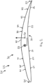
- depicts an embodiment of an airfoil profile according to the invention;
- Fig. 3
- depicts a diagram of the radius of curvature of an upper airfoil surface; and
- Fig. 4
- depicts a diagram of the radius of curvature of a lower airfoil surface.
- Referring to
Fig. 1 anaircraft 10 is depicted. Theaircraft 10 is configured as an unmanned aerial system (UAS) 11. The UAS 11 comprises aUAS body 12 to which a pair ofwings 13 is attached. The UAS 11 has a plurality ofcontrol surfaces 14 that are arranged in manner known per se. The UAS 11 further comprises apropeller 20 for propulsion. - The
propeller 20 comprises ahub 21 which supports a plurality ofpropeller blades 22. - Referring to
Fig. 2 , a thepropeller blade 22 has anairfoil profile 30. Theairfoil profile 30 corresponds to a cross-section through thepropeller blade 22 along plane II-II. - As depicted, the
airfoil profile 30 is viewed along a spanwise direction from the tip of thepropeller blade 22 towards the root of thepropeller blade 22 that is supported by thehub 21. The spanwise direction therefore corresponds to a direction orthogonal to the drawing plane ofFig. 2 . - The
airfoil profile 30 comprises aleading edge portion 31 and a trailingedge portion 32. Theleading edge portion 31 and the trailingedge portion 32 are spaced apart along a chordwise direction. The chordwise direction lies in the drawing plane ofFig. 2 . The chordwise direction and the spanwise direction define a vertical direction, that is orthogonal to both the chordwise and the spanwise direction. In other words the chordwise, spanwise and vertical directions are mutually orthogonal to each other. - The
airfoil profile 30 comprises anairfoil centroid 33. Theairfoil centroid 33 is also called elastic axis. Theairfoil centroid 33 extends in the spanwise direction. Theairfoil centroid 33 is influenced by the shape of theairfoil profile 30 which is subsequently described in more detail. - The
airfoil profile 30 comprises anupper airfoil surface 40. Theupper airfoil surface 40 extends between theleading edge portion 31 and the trailingedge portion 32. Theupper airfoil surface 40 is defined by a 6th-order polynomial of the form:
- where x corresponds to the percentage of the chord length going from 0 % to 100 %, and the an are coefficients that depend on the thickness of the
airfoil profile 30. The result of the polynomial is the distance from 0 along the vertical direction in percent of the chord length. In this embodiment, the thickness varies from 8 % close to the tip of thepropeller blade 22 to 18 % close to the root of thepropeller blade 22. - a6 is defined by - 0.0078 t2 - 0.043 t - 3.4025;
- a5 is defined by 0.0249 t2 + 0.0917 t + 10.762;
- a4 is defined by - 0.0301 t2 - 0.0608 t - 12.691;
- a3 is defined by 0.0165 t2 + 0.0272 t + 6.6256;
- a2 is defined by - 0.0041 t2 - 0.0396 t - 1.6238;
- a1 is defined by 0.0005 t2 + 0.0232 t + 0.332; and
- a0 is defined by 0.0009 t + 0.0035;
- where t is the thickness inserted into the respective equation in percent, e.g. 10 % thickness corresponds to t = 10.
- Preferably, the
upper airfoil surface 40 lies within a tolerance band of ± 5 %, preferably ± 3 %, more prefably ± 1 %, most preferably ± 0.3% from the polynomial of equation (1). - The radius of curvature ry of the
upper airfoil surface 40 is defined in the conventional manner as:
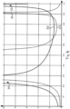
Fig. 3 illustrates ry vs. the normalized chordlength for t = 8 % (continuous line) and t = 18 % (broken line). - The
upper airfoil surface 40 comprises a first uppercurved portion 41. The first uppercurved portion 41 has a maximum modulus of the radius of curvature (see equation (2)) from from 1.8 times to 4.4 times of the chord length depending on the thickness. When viewed along the spanwise direction, the maximum modulus of the radius of curvature continuously decreases. - The maximum modulus of the radius of curvature for the first upper
curved portion 41 is located between theleading edge portion 31 and theairfoil centroid 33 along the chordwise direction. This maximum is preferably located from 21 % to 23 % of the chord length. - The first upper
curved portion 41 has a spatial extension along the chordwise direction that is measured as the full-width at half-maximum (FWHM) of the radius of curvature. With the previously selected coefficients, the spatial extension of the first uppercurved portion 41 along the chordwise direction is in the range of 15 percentage points to 22 percentage points. When viewed along the spanwise direction, the spatial extension of the first uppercurved portion 41 continuously increases. - The
upper airfoil surface 40 comprises a second uppercurved portion 42. The second uppercurved portion 42 has a maximum modulus of the radius of curvature (see equation (2)) from from 1.9 times to 2.1 times of the chord length depending on the thickness. When viewed along the spanwise direction, the maximum modulus of the radius of curvature continuously increases. - The maximum modulus of the radius of curvature for the second upper
curved portion 42 is located between the trailingedge portion 32 and theairfoil centroid 33 along the chordwise direction. This maximum is preferably located from 79 % to 80 % of the chord length. - The second upper
curved portion 42 has a spatial extension along the chordwise direction that is measured as the full-width at half-maximum (FWHM) of the radius of curvature. With the previously selected coefficients, the spatial extension of the second uppercurved portion 42 along the chordwise direction is in the range of 19 percentage points to 26 percentage points. When viewed along the spanwise direction, the spatial extension of the second uppercurved portion 42 continuously decreases. - The
upper airfoil surface 40 comprises a third uppercurved portion 43. The third uppercurved portion 43 has a minimum modulus of the radius of curvature (see equation (2)) from from 0.5 times to 0.8 times of the chord length depending on the thickness. When viewed along the spanwise direction, the maximum modulus of the radius of curvature continuously decreases. - The minimum modulus of the radius of curvature for the third upper
curved portion 43 is located between theleading edge portion 31 and the trailingedge portion 32 along the chordwise direction. This minimum is preferably located from 50 % to 52 % of the chord length. - The third upper
curved portion 43 has a spatial extension along the chordwise direction that is measured as the full-width at double-minimum (FWDM) of the radius of curvature. With the previously selected coefficients, the spatial extension of the third uppercurved portion 43 along the chordwise direction is in the range of 36 percentage points to 40 percentage points. When viewed along the spanwise direction, the spatial extension of the third uppercurved portion 43 continuously decreases. - The
airfoil profile 30 comprises alower airfoil surface 50. Thelower airfoil surface 50 extends between theleading edge portion 31 and the trailingedge portion 32. Thelower airfoil surface 50 is defined by a 6th-order polynomial of the form:
- where x corresponds to the percentage of the chord length going from 0 % to 100 %, and the bn are coefficients that depend on the thickness of the
airfoil profile 30. The result of the polynomial is the distance from 0 along the vertical direction in percent of the chord length. In this embodiment, the thickness varies from 8 % close to the tip of thepropeller blade 22 to 18 % close to the root of thepropeller blade 22. - b6 is defined by 0.0021 t2 + 0.3834 t - 2.2564;
- b5 is defined by - 0.0068 t2 - 1.1895 t + 7.0593;
- b4 is defined by 0.0082 t2 + 1.4243 t - 8.3201;
- b3 is defined by - 0.0042 t2 - 0.8427 t + 4.4385;
- b2 is defined by 0.0006 t2 + 0.2768 t - 1.2628;
- b1 is defined by - 0.0008 t4 + 0.0439 t3 - 0.9162 t2 + 8.3143 t - 27.838; and
- b0 is defined by - 0.00008 t + 0.0017;
- where t is the thickness inserted into the respective equation in percent, e.g. 10 % thickness corresponds to t = 10. Preferably, the
lower airfoil surface 50 lies within a tolerance band of ± 5 %, preferably ± 3 %, more prefably ± 1 %, most preferably ± 0.3% from the polynomial of equation (3). - The radius of curvature rz of the
lower airfoil surface 50 is defined in the conventional manner as:
Fig. 4 illustrates rz vs. the normalized chordlength for t = 8 % (continuous line) and t = 18 % (broken line). - It should be noted that z" has at least one zero at one point along the chord length. For purposes of this disclosure, a portion that has a radius of curvature larger than 10 times the chord length is deemed to be flat.
- The
lower airfoil surface 50 comprises a first lowerflat portion 51. The first lowerflat portion 51 exceeds modulus of the radius of curvature (see equation (4)) of 10. The first lowerflat portion 51 is located between theleading edge portion 31 and theairfoil centroid 33 along the chordwise direction. The location can be defined by the first zero of z" from theleading edge portion 31, i.e. the zero closest to theleading edge portion 31. The zero is preferably located from 25 % to 30 % of the chord length, more preferably from 25 % to 29 % of the chord length, more preferably from 25.5 % to 28.8 % of the chord length. - The first lower
flat portion 51 has a spatial extension along the chordwise direction that is measured as the full-width at a radius of curvature of 10 (FW@R10). With the previously selected coefficients, the spatial extension of the first lowerflat portion 51 along the chordwise direction is in the range of 8 percentage points to 30 percentage points. When viewed along the spanwise direction, the spatial extension of the first lowerflat portion 51 continuously increases. - The
lower airfoil surface 50 comprises a second lowerflat portion 52. The second lowerflat portion 52 exceeds modulus of the radius of curvature (see equation (4)) of 10. The second lowerflat portion 52 is located between theleading edge portion 31 and the trailingedge portion 32 along the chordwise direction. The location can be defined by the last zero of z" from theleading edge portion 31, i.e. the zero closest to the trailingedge portion 32. The zero is preferably located from 36 % to 52 % of the chord length. - The second lower
flat portion 52 has a spatial extension along the chordwise direction that is measured as the full-width at a radius of curvature of 10 (FW@R10). With the previously selected coefficients, the spatial extension of the second lowerflat portion 52 along the chordwise direction is in the range of 1 percentage points to 3 percentage points. When viewed along the spanwise direction, the spatial extension of the second lowerflat portion 52 continuously decreases. - The
lower airfoil surface 50 comprises a lowercurved portion 53. The lowercurved portion 53 has a minimum modulus of the radius of curvature (see equation (4)) from 0.85 times to 1.35 times of the chord length depending on the thickness. When viewed along the spanwise direction, the maximum modulus of the radius of curvature continuously decreases. - The minimum modulus of the radius of curvature for the lower
curved portion 53 is located between the trailingedge portion 32 and theairfoil centroid 33 along the chordwise direction. This minimum is preferably located from 75 % to 79 % of the chord length, more preferably from 77 % to 78 % of the chord length. - The lower
curved portion 53 has a spatial extension along the chordwise direction that is measured as the full-width at double-minimum (FWDM) of the radius of curvature. With the previously selected coefficients, the spatial extension of the lowercurved portion 53 along the chordwise direction is in the range of 23 percentage points to 45 percentage points. When viewed along the spanwise direction, the spatial extension of the lowercurved portion 53 continuously decreases. - In order to reduce noise, the invention proposes an airfoil profile (30) for an aircraft (10), such as an unmanned aerial system (11). The airfoil profile (30) comprises a leading edge portion (31) and a trailing edge portion (32) that are spaced apart along a chordwise direction, an airfoil centroid (33); and an upper airfoil surface (40) and a lower airfoil surface (50). The airfoil surfaces (40, 50) are shaped such that the pressure center (Cp) of the lifting force is arranged at the same chord location as the airfoil centroid (33) or closer to the trailing edge portion (32) along the chordwise direction than the airfoil centroid (33). With this, a pitch-down momentum is generated that urges the leading edge portion (31) towards a lower angle of attack (AoA).
-
- 10
- aircraft
- 11
- unmanned aerial system (UAS)
- 12
- UAS body
- 13
- wing
- 14
- control surface
- 20
- propeller
- 21
- hub
- 22
- propeller blade
- 30
- airfoil profile
- 31
- leading edge portion
- 32
- trailing edge portion
- 33
- airfoil centroid
- 40
- upper airfoil surface
- 41
- first upper curved portion
- 42
- second upper curved portion
- 43
- third upper curved portion
- 50
- lower airfoil surface
- 51
- first lower flat portion
- 52
- second lower flat portion
- 53
- lower curved portion
- Cp
- pressure center
Claims (15)
- An airfoil profile (30) for an aircraft (10), such as an unmanned aerial system (11), the airfoil profile (30) being configured for reducing a noise level, the airfoil profile (30) comprising:- a leading edge portion (31) and a trailing edge portion (32) that are spaced apart along a chordwise direction;- an airfoil centroid (33) that is arranged from 40 % to 60 % of a chord length along the chordwise direction; and- an upper airfoil surface (40) and a lower airfoil surface (50) that are shaped so as to generate a lifting force in a manner such that a pressure center (Cp) of the lifting force is arranged at the same chord location as the airfoil centroid (33) or closer to the trailing edge portion (32) along the chordwise direction than the airfoil centroid (33).
- The airfoil profile (30) according to claim 1, wherein the airfoil centroid (33) is arranged from 43 % to 55 %, preferably from 45 % to 54 %, of the chord length along the chordwise direction.
- The airfoil profile (30) according to any of the preceding claims, wherein the upper and lower airfoil surface (50)s are shaped such that the pressure center (Cp) of the lifting force is arranged from 40 % to 60 %, preferably from 43 % to 55 %, more preferably from 45 % to 54 %, of the chord length along the chordwise direction.
- The airfoil profile (30) according to any of the preceding claims, wherein the upper airfoil surface (40) comprises a first upper curved portion (41) that is arranged between the leading edge portion (31) and the airfoil centroid (33) along the chordwise direction, preferably from 20 % to 30 % of the chord length, more preferably from 20 % to 25 % of the chord length, more preferably from 21 % to 23 % of the chord length.
- The airfoil profile (30) according to claim 4, wherein the first upper curved portion (41) has a maximum modulus of the radius of curvature from 1.8 times to 4.4 times the chord length, wherein preferably the maximum modulus of the radius of curvature continuously decreases from an airfoil outward portion towards an airfoil inward portion along a spanwise direction.
- The airfoil profile (30) according to any of the preceding claims, wherein the upper airfoil surface (40) comprises a second upper curved portion (42) that is arranged between the airfoil centroid (33) and the trailing edge portion (32) along the chordwise direction, preferably from 75 % to 85 % of the chord length, more preferably from 78 % to 82 % of the chord length, more preferably from 79 % to 80 % of the chord length.
- The airfoil profile (30) according to claim 6, wherein the second upper curved portion (42) has a maximum modulus of the radius of curvature from 1.9 times to 2.1 times the chord length, wherein preferably the maximum modulus of the radius of curvature continuously increases from an airfoil outward portion towards an airfoil inward portion along a spanwise direction.
- The airfoil profile (30) according to any of the preceding claims, wherein the upper airfoil surface (40) comprises a third upper curved portion (43) that is arranged between the leading edge portion (31) and the trailing edge portion (32) along the chordwise direction, preferably from 45 % to 55 % of the chord length, more preferably from 49 % to 53 % of the chord length, more preferably from 50 % to 52 % of the chord length.
- The airfoil profile (30) according to any of the preceding claims, wherein the third upper curved portion (43) has a maximum modulus of the radius of curvature from 0.5 times to 0.8 times the chord length, wherein preferably the minimum modulus of the radius of curvature continuously decreases from an airfoil outward portion towards an airfoil inward portion along a spanwise direction.
- The airfoil profile (30) according to any of the preceding claims, wherein the lower airfoil surface (50) comprises a first lower flat portion (51) that is arranged between the leading edge portion (31) and the airfoil centroid (33) along the chordwise direction, preferably from 25 % to 30 % of the chord length, more preferably from 25 % to 29 % of the chord length, more preferably from 25.5 % to 28.8 % of the chord length.
- The airfoil profile (30) according to any of the preceding claims, wherein the lower airfoil surface (50) comprises a second lower flat portion (52) that is arranged between the leading edge portion (31) and the trailing edge portion (32) along the chordwise direction, preferably from 35 % to 55 % of the chord length, more preferably from 36 % to 52 % of the chord length.
- The airfoil profile (30) according to any of the preceding claims, wherein the lower airfoil surface (50) comprises a lower curved portion (53) that is arranged between the airfoil centroid (33) and the trailing edge portion (32) along the chordwise direction, preferably from 70 % to 80 % of the chord length, more preferably from 75 % to 79 % of the chord length, more preferably from 77 % to 78 % of the chord length.
- A wing (13) or a propeller blade (22) for an aircraft (10) comprising an airfoil profile (30) according to any of the preceding claims.
- A propeller (20) for an aircraft (10) comprising a hub (21) and at least one propeller blade (22) according to claim 13 that is supported by the hub (21).
- An aircraft (10), preferably an unmanned aerial system (11), comprising a wing (13) or a propeller blade (22) according to claim 13 and/or a propeller (20) according to claim 14.
Priority Applications (3)
| Application Number | Priority Date | Filing Date | Title |
|---|---|---|---|
| EP22202663.5A EP4357240B1 (en) | 2022-10-20 | 2022-10-20 | Propeller blade using an airfoil profile |
| US18/489,411 US12534233B2 (en) | 2022-10-20 | 2023-10-18 | Airfoil profile for an aircraft and aerodynamic surfaces using said airfoil profile |
| CN202311364053.7A CN117917361A (en) | 2022-10-20 | 2023-10-20 | Airfoil profile for aircraft and aerodynamic surface using the same |
Applications Claiming Priority (1)
| Application Number | Priority Date | Filing Date | Title |
|---|---|---|---|
| EP22202663.5A EP4357240B1 (en) | 2022-10-20 | 2022-10-20 | Propeller blade using an airfoil profile |
Publications (2)
| Publication Number | Publication Date |
|---|---|
| EP4357240A1 true EP4357240A1 (en) | 2024-04-24 |
| EP4357240B1 EP4357240B1 (en) | 2025-04-02 |
Family
ID=83899627
Family Applications (1)
| Application Number | Title | Priority Date | Filing Date |
|---|---|---|---|
| EP22202663.5A Active EP4357240B1 (en) | 2022-10-20 | 2022-10-20 | Propeller blade using an airfoil profile |
Country Status (3)
| Country | Link |
|---|---|
| US (1) | US12534233B2 (en) |
| EP (1) | EP4357240B1 (en) |
| CN (1) | CN117917361A (en) |
Citations (1)
| Publication number | Priority date | Publication date | Assignee | Title |
|---|---|---|---|---|
| US3822105A (en) * | 1971-09-22 | 1974-07-02 | United Aircraft Corp | Helicopter blade |
Family Cites Families (15)
| Publication number | Priority date | Publication date | Assignee | Title |
|---|---|---|---|---|
| GB1554713A (en) * | 1975-03-04 | 1979-10-24 | Secr Defence | Wings |
| US4641796A (en) * | 1983-09-30 | 1987-02-10 | The Boeing Company | Airfoil |
| GB9105767D0 (en) * | 1991-03-19 | 1991-11-06 | British Aerospace | Wing root design of forward swept wings |
| US6382921B1 (en) * | 2001-01-30 | 2002-05-07 | Seimens Vdo Automotive, Inc. | Low reynolds number, low drag, high lift airfoil |
| US6607164B2 (en) * | 2001-10-22 | 2003-08-19 | Toyota Motor Sales, U.S.A., Inc. | Wing airfoil |
| JP4237980B2 (en) * | 2002-06-12 | 2009-03-11 | 本田技研工業株式会社 | Laminar airfoil for aircraft main wing |
| US8186616B2 (en) * | 2004-12-21 | 2012-05-29 | Israel Aerospace Industries Ltd. | Hybrid transonic-subsonic aerofoils |
| IL176022A (en) * | 2006-05-30 | 2011-11-30 | Israel Aerospace Ind Ltd | Wings for aircraft |
| FR2953198B1 (en) * | 2009-12-02 | 2012-05-11 | Jean-Michel Simon | SUSTENTATION AND PROPULSION DEVICE |
| US10933970B2 (en) * | 2018-03-28 | 2021-03-02 | The Boeing Company | Aircraft with strut-braced wing system |
| GB201911291D0 (en) * | 2019-08-07 | 2019-09-18 | Rolls Royce Plc | Aerofoil |
| TR202022599A1 (en) * | 2020-12-31 | 2022-07-21 | Tusas Tuerk Havacilik Ve Uzay Sanayii Anonim Sirketi | a helicopter |
| EP4313758A1 (en) * | 2021-03-22 | 2024-02-07 | Baylor University | Propeller with unloaded tip zone and method |
| US12358606B1 (en) * | 2024-05-31 | 2025-07-15 | King Fahd University Of Petroleum And Minerals | Airfoil for an aircraft for superior supersonic aerodynamic performance |
| CN118665747A (en) * | 2024-08-16 | 2024-09-20 | 北航长鹰航空科技(台州)有限公司 | Laminar flow airfoil with high lift-drag ratio for long-endurance unmanned aerial vehicle |
-
2022
- 2022-10-20 EP EP22202663.5A patent/EP4357240B1/en active Active
-
2023
- 2023-10-18 US US18/489,411 patent/US12534233B2/en active Active
- 2023-10-20 CN CN202311364053.7A patent/CN117917361A/en active Pending
Patent Citations (1)
| Publication number | Priority date | Publication date | Assignee | Title |
|---|---|---|---|---|
| US3822105A (en) * | 1971-09-22 | 1974-07-02 | United Aircraft Corp | Helicopter blade |
Non-Patent Citations (2)
| Title |
|---|
| UIUC APPLIED AERODYNAMICS GROUP - DEPARTMENT OF AEROSPACE ENGINEERING - UNIVERSITY OF ILLINOIS AT URBANA-CHAMPAIGN: "UIUC Airfoil Coordinates Database - Goe 8K entry", 4 June 2015 (2015-06-04), XP093056721, Retrieved from the Internet <URL:https://web.archive.org/web/20150604012958/http://m-selig.ae.illinois.edu/ads/coord/goe08k.dat> [retrieved on 20230622] * |
| WATKINSON, JOHN: "The art of the helicopter", 31 December 2004, ELSEVIER, Oxford, ISBN: 0750657154, XP040425963 * |
Also Published As
| Publication number | Publication date |
|---|---|
| CN117917361A (en) | 2024-04-23 |
| US20240132236A1 (en) | 2024-04-25 |
| US12534233B2 (en) | 2026-01-27 |
| US20240228073A9 (en) | 2024-07-11 |
| EP4357240B1 (en) | 2025-04-02 |
Similar Documents
| Publication | Publication Date | Title |
|---|---|---|
| US4314795A (en) | Advanced airfoils for helicopter rotor application | |
| US9598167B2 (en) | Morphing airfoil leading edge | |
| US6361279B1 (en) | Blade profile for aircraft rotor and rotor comprising same | |
| US9555895B2 (en) | Motor pylons for a kite and airborne power generation system using same | |
| US3822105A (en) | Helicopter blade | |
| US10858093B2 (en) | Thick airfoil shapes for blade necks and for blade cuff fairings for an aircraft rotor | |
| US20120251326A1 (en) | Noise and performance improved rotor blade for a helicopter | |
| CN202642093U (en) | Propeller and aircraft with propeller | |
| CN107428410A (en) | Propeller-driven propulsion system integrated with fuselage | |
| CN107804458A (en) | A kind of adaptive variation rigidity arcuate limbs for being used for mini-sized flap wings and flutterring rotor craft | |
| Boermans | Research on sailplane aerodynamics at Delft University of Technology | |
| Fertis | New airfoil-design concept with improved aerodynamic characteristics | |
| EP4357240B1 (en) | Propeller blade using an airfoil profile | |
| JPH06264701A (en) | Fluid machine | |
| US11192644B2 (en) | Aircraft rotor blade sleeve having a protuberance in its rear zone, and a rotor provided with such a sleeve | |
| CN210653616U (en) | High pneumatic performance unmanned aerial vehicle | |
| Rice et al. | Control of reversed flow in static and dynamic conditions using camber morphing airfoils | |
| US11396367B2 (en) | Vortex reduction apparatus for use with airfoils | |
| GB2474511A (en) | Variable pitch aerofoil blade | |
| WO2021201811A2 (en) | Partially flexible airfoil formed with silicone based flexible material | |
| Rinoie et al. | Experimental studies of a 70-degree delta wing with vortex flaps | |
| Alvarez Calderon | Rotating cylinder flaps for V/STOL aircraft: some aspects of an investigation into the rotating cylinder flap high lift system for V/STOL aircraft conducted jointly by the Peruvian Air Force and the National University of Engineering of Peru | |
| Al-Atabi | Aerodynamics of wing tip sails | |
| CN119622922B (en) | Aeronautical propeller aerodynamic performance calculation method under wing and nacelle configuration | |
| Eppler | Airfoil data |
Legal Events
| Date | Code | Title | Description |
|---|---|---|---|
| PUAI | Public reference made under article 153(3) epc to a published international application that has entered the european phase |
Free format text: ORIGINAL CODE: 0009012 |
|
| STAA | Information on the status of an ep patent application or granted ep patent |
Free format text: STATUS: THE APPLICATION HAS BEEN PUBLISHED |
|
| AK | Designated contracting states |
Kind code of ref document: A1 Designated state(s): AL AT BE BG CH CY CZ DE DK EE ES FI FR GB GR HR HU IE IS IT LI LT LU LV MC ME MK MT NL NO PL PT RO RS SE SI SK SM TR |
|
| STAA | Information on the status of an ep patent application or granted ep patent |
Free format text: STATUS: REQUEST FOR EXAMINATION WAS MADE |
|
| GRAP | Despatch of communication of intention to grant a patent |
Free format text: ORIGINAL CODE: EPIDOSNIGR1 |
|
| STAA | Information on the status of an ep patent application or granted ep patent |
Free format text: STATUS: GRANT OF PATENT IS INTENDED |
|
| 17P | Request for examination filed |
Effective date: 20241023 |
|
| RBV | Designated contracting states (corrected) |
Designated state(s): AL AT BE BG CH CY CZ DE DK EE ES FI FR GB GR HR HU IE IS IT LI LT LU LV MC ME MK MT NL NO PL PT RO RS SE SI SK SM TR |
|
| INTG | Intention to grant announced |
Effective date: 20241126 |
|
| GRAS | Grant fee paid |
Free format text: ORIGINAL CODE: EPIDOSNIGR3 |
|
| GRAA | (expected) grant |
Free format text: ORIGINAL CODE: 0009210 |
|
| STAA | Information on the status of an ep patent application or granted ep patent |
Free format text: STATUS: THE PATENT HAS BEEN GRANTED |
|
| AK | Designated contracting states |
Kind code of ref document: B1 Designated state(s): AL AT BE BG CH CY CZ DE DK EE ES FI FR GB GR HR HU IE IS IT LI LT LU LV MC ME MK MT NL NO PL PT RO RS SE SI SK SM TR |
|
| REG | Reference to a national code |
Ref country code: GB Ref legal event code: FG4D |
|
| REG | Reference to a national code |
Ref country code: CH Ref legal event code: EP |
|
| REG | Reference to a national code |
Ref country code: IE Ref legal event code: FG4D |
|
| REG | Reference to a national code |
Ref country code: DE Ref legal event code: R096 Ref document number: 602022012520 Country of ref document: DE |
|
| REG | Reference to a national code |
Ref country code: NL Ref legal event code: MP Effective date: 20250402 |
|
| PG25 | Lapsed in a contracting state [announced via postgrant information from national office to epo] |
Ref country code: NL Free format text: LAPSE BECAUSE OF FAILURE TO SUBMIT A TRANSLATION OF THE DESCRIPTION OR TO PAY THE FEE WITHIN THE PRESCRIBED TIME-LIMIT Effective date: 20250402 |
|
| REG | Reference to a national code |
Ref country code: AT Ref legal event code: MK05 Ref document number: 1781087 Country of ref document: AT Kind code of ref document: T Effective date: 20250402 |
|
| PG25 | Lapsed in a contracting state [announced via postgrant information from national office to epo] |
Ref country code: FI Free format text: LAPSE BECAUSE OF FAILURE TO SUBMIT A TRANSLATION OF THE DESCRIPTION OR TO PAY THE FEE WITHIN THE PRESCRIBED TIME-LIMIT Effective date: 20250402 Ref country code: PT Free format text: LAPSE BECAUSE OF FAILURE TO SUBMIT A TRANSLATION OF THE DESCRIPTION OR TO PAY THE FEE WITHIN THE PRESCRIBED TIME-LIMIT Effective date: 20250804 Ref country code: ES Free format text: LAPSE BECAUSE OF FAILURE TO SUBMIT A TRANSLATION OF THE DESCRIPTION OR TO PAY THE FEE WITHIN THE PRESCRIBED TIME-LIMIT Effective date: 20250402 |
|
| REG | Reference to a national code |
Ref country code: LT Ref legal event code: MG9D |
|
| PG25 | Lapsed in a contracting state [announced via postgrant information from national office to epo] |
Ref country code: GR Free format text: LAPSE BECAUSE OF FAILURE TO SUBMIT A TRANSLATION OF THE DESCRIPTION OR TO PAY THE FEE WITHIN THE PRESCRIBED TIME-LIMIT Effective date: 20250703 Ref country code: NO Free format text: LAPSE BECAUSE OF FAILURE TO SUBMIT A TRANSLATION OF THE DESCRIPTION OR TO PAY THE FEE WITHIN THE PRESCRIBED TIME-LIMIT Effective date: 20250702 |
|
| PG25 | Lapsed in a contracting state [announced via postgrant information from national office to epo] |
Ref country code: PL Free format text: LAPSE BECAUSE OF FAILURE TO SUBMIT A TRANSLATION OF THE DESCRIPTION OR TO PAY THE FEE WITHIN THE PRESCRIBED TIME-LIMIT Effective date: 20250402 |
|
| PG25 | Lapsed in a contracting state [announced via postgrant information from national office to epo] |
Ref country code: BG Free format text: LAPSE BECAUSE OF FAILURE TO SUBMIT A TRANSLATION OF THE DESCRIPTION OR TO PAY THE FEE WITHIN THE PRESCRIBED TIME-LIMIT Effective date: 20250402 |
|
| PG25 | Lapsed in a contracting state [announced via postgrant information from national office to epo] |
Ref country code: HR Free format text: LAPSE BECAUSE OF FAILURE TO SUBMIT A TRANSLATION OF THE DESCRIPTION OR TO PAY THE FEE WITHIN THE PRESCRIBED TIME-LIMIT Effective date: 20250402 |
|
| PG25 | Lapsed in a contracting state [announced via postgrant information from national office to epo] |
Ref country code: AT Free format text: LAPSE BECAUSE OF FAILURE TO SUBMIT A TRANSLATION OF THE DESCRIPTION OR TO PAY THE FEE WITHIN THE PRESCRIBED TIME-LIMIT Effective date: 20250402 |
|
| PG25 | Lapsed in a contracting state [announced via postgrant information from national office to epo] |
Ref country code: RS Free format text: LAPSE BECAUSE OF FAILURE TO SUBMIT A TRANSLATION OF THE DESCRIPTION OR TO PAY THE FEE WITHIN THE PRESCRIBED TIME-LIMIT Effective date: 20250702 |
|
| PG25 | Lapsed in a contracting state [announced via postgrant information from national office to epo] |
Ref country code: IS Free format text: LAPSE BECAUSE OF FAILURE TO SUBMIT A TRANSLATION OF THE DESCRIPTION OR TO PAY THE FEE WITHIN THE PRESCRIBED TIME-LIMIT Effective date: 20250802 |
|
| PG25 | Lapsed in a contracting state [announced via postgrant information from national office to epo] |
Ref country code: LV Free format text: LAPSE BECAUSE OF FAILURE TO SUBMIT A TRANSLATION OF THE DESCRIPTION OR TO PAY THE FEE WITHIN THE PRESCRIBED TIME-LIMIT Effective date: 20250402 |
|
| REG | Reference to a national code |
Ref country code: DE Ref legal event code: R097 Ref document number: 602022012520 Country of ref document: DE |
|
| PGFP | Annual fee paid to national office [announced via postgrant information from national office to epo] |
Ref country code: DE Payment date: 20251021 Year of fee payment: 4 |
|
| PG25 | Lapsed in a contracting state [announced via postgrant information from national office to epo] |
Ref country code: SM Free format text: LAPSE BECAUSE OF FAILURE TO SUBMIT A TRANSLATION OF THE DESCRIPTION OR TO PAY THE FEE WITHIN THE PRESCRIBED TIME-LIMIT Effective date: 20250402 Ref country code: DK Free format text: LAPSE BECAUSE OF FAILURE TO SUBMIT A TRANSLATION OF THE DESCRIPTION OR TO PAY THE FEE WITHIN THE PRESCRIBED TIME-LIMIT Effective date: 20250402 |
|
| PGFP | Annual fee paid to national office [announced via postgrant information from national office to epo] |
Ref country code: FR Payment date: 20251030 Year of fee payment: 4 |
|
| PG25 | Lapsed in a contracting state [announced via postgrant information from national office to epo] |
Ref country code: CZ Free format text: LAPSE BECAUSE OF FAILURE TO SUBMIT A TRANSLATION OF THE DESCRIPTION OR TO PAY THE FEE WITHIN THE PRESCRIBED TIME-LIMIT Effective date: 20250402 |
|
| PG25 | Lapsed in a contracting state [announced via postgrant information from national office to epo] |
Ref country code: EE Free format text: LAPSE BECAUSE OF FAILURE TO SUBMIT A TRANSLATION OF THE DESCRIPTION OR TO PAY THE FEE WITHIN THE PRESCRIBED TIME-LIMIT Effective date: 20250402 |
|
| PG25 | Lapsed in a contracting state [announced via postgrant information from national office to epo] |
Ref country code: SK Free format text: LAPSE BECAUSE OF FAILURE TO SUBMIT A TRANSLATION OF THE DESCRIPTION OR TO PAY THE FEE WITHIN THE PRESCRIBED TIME-LIMIT Effective date: 20250402 |
|
| PG25 | Lapsed in a contracting state [announced via postgrant information from national office to epo] |
Ref country code: IT Free format text: LAPSE BECAUSE OF FAILURE TO SUBMIT A TRANSLATION OF THE DESCRIPTION OR TO PAY THE FEE WITHIN THE PRESCRIBED TIME-LIMIT Effective date: 20250402 |
|
| PLBE | No opposition filed within time limit |
Free format text: ORIGINAL CODE: 0009261 |
|
| STAA | Information on the status of an ep patent application or granted ep patent |
Free format text: STATUS: NO OPPOSITION FILED WITHIN TIME LIMIT |
|
| REG | Reference to a national code |
Ref country code: CH Ref legal event code: L10 Free format text: ST27 STATUS EVENT CODE: U-0-0-L10-L00 (AS PROVIDED BY THE NATIONAL OFFICE) Effective date: 20260211 |
|
| PG25 | Lapsed in a contracting state [announced via postgrant information from national office to epo] |
Ref country code: RO Free format text: LAPSE BECAUSE OF FAILURE TO SUBMIT A TRANSLATION OF THE DESCRIPTION OR TO PAY THE FEE WITHIN THE PRESCRIBED TIME-LIMIT Effective date: 20250402 |
|
| 26N | No opposition filed |
Effective date: 20260105 |