EP4357137A1 - Inkjet recording device and program - Google Patents
Inkjet recording device and program Download PDFInfo
- Publication number
- EP4357137A1 EP4357137A1 EP22824704.5A EP22824704A EP4357137A1 EP 4357137 A1 EP4357137 A1 EP 4357137A1 EP 22824704 A EP22824704 A EP 22824704A EP 4357137 A1 EP4357137 A1 EP 4357137A1
- Authority
- EP
- European Patent Office
- Prior art keywords
- carriage
- inkjet head
- speed
- recording device
- inkjet
- Prior art date
- Legal status (The legal status is an assumption and is not a legal conclusion. Google has not performed a legal analysis and makes no representation as to the accuracy of the status listed.)
- Granted
Links
Images




Classifications
-
- B—PERFORMING OPERATIONS; TRANSPORTING
- B41—PRINTING; LINING MACHINES; TYPEWRITERS; STAMPS
- B41J—TYPEWRITERS; SELECTIVE PRINTING MECHANISMS, i.e. MECHANISMS PRINTING OTHERWISE THAN FROM A FORME; CORRECTION OF TYPOGRAPHICAL ERRORS
- B41J2/00—Typewriters or selective printing mechanisms characterised by the printing or marking process for which they are designed
- B41J2/005—Typewriters or selective printing mechanisms characterised by the printing or marking process for which they are designed characterised by bringing liquid or particles selectively into contact with a printing material
- B41J2/01—Ink jet
- B41J2/015—Ink jet characterised by the jet generation process
- B41J2/04—Ink jet characterised by the jet generation process generating single droplets or particles on demand
- B41J2/045—Ink jet characterised by the jet generation process generating single droplets or particles on demand by pressure, e.g. electromechanical transducers
- B41J2/04501—Control methods or devices therefor, e.g. driver circuits, control circuits
- B41J2/04503—Control methods or devices therefor, e.g. driver circuits, control circuits aiming at compensating carriage speed
-
- B—PERFORMING OPERATIONS; TRANSPORTING
- B41—PRINTING; LINING MACHINES; TYPEWRITERS; STAMPS
- B41J—TYPEWRITERS; SELECTIVE PRINTING MECHANISMS, i.e. MECHANISMS PRINTING OTHERWISE THAN FROM A FORME; CORRECTION OF TYPOGRAPHICAL ERRORS
- B41J19/00—Character- or line-spacing mechanisms
- B41J19/18—Character-spacing or back-spacing mechanisms; Carriage return or release devices therefor
- B41J19/20—Positive-feed character-spacing mechanisms
- B41J19/202—Drive control means for carriage movement
-
- B—PERFORMING OPERATIONS; TRANSPORTING
- B41—PRINTING; LINING MACHINES; TYPEWRITERS; STAMPS
- B41J—TYPEWRITERS; SELECTIVE PRINTING MECHANISMS, i.e. MECHANISMS PRINTING OTHERWISE THAN FROM A FORME; CORRECTION OF TYPOGRAPHICAL ERRORS
- B41J2/00—Typewriters or selective printing mechanisms characterised by the printing or marking process for which they are designed
- B41J2/005—Typewriters or selective printing mechanisms characterised by the printing or marking process for which they are designed characterised by bringing liquid or particles selectively into contact with a printing material
- B41J2/01—Ink jet
- B41J2/015—Ink jet characterised by the jet generation process
- B41J2/04—Ink jet characterised by the jet generation process generating single droplets or particles on demand
- B41J2/045—Ink jet characterised by the jet generation process generating single droplets or particles on demand by pressure, e.g. electromechanical transducers
- B41J2/04501—Control methods or devices therefor, e.g. driver circuits, control circuits
- B41J2/04581—Control methods or devices therefor, e.g. driver circuits, control circuits controlling heads based on piezoelectric elements
-
- B—PERFORMING OPERATIONS; TRANSPORTING
- B41—PRINTING; LINING MACHINES; TYPEWRITERS; STAMPS
- B41J—TYPEWRITERS; SELECTIVE PRINTING MECHANISMS, i.e. MECHANISMS PRINTING OTHERWISE THAN FROM A FORME; CORRECTION OF TYPOGRAPHICAL ERRORS
- B41J25/00—Actions or mechanisms not otherwise provided for
- B41J25/304—Bodily-movable mechanisms for print heads or carriages movable towards or from paper surface
- B41J25/308—Bodily-movable mechanisms for print heads or carriages movable towards or from paper surface with print gap adjustment mechanisms
-
- B—PERFORMING OPERATIONS; TRANSPORTING
- B41—PRINTING; LINING MACHINES; TYPEWRITERS; STAMPS
- B41J—TYPEWRITERS; SELECTIVE PRINTING MECHANISMS, i.e. MECHANISMS PRINTING OTHERWISE THAN FROM A FORME; CORRECTION OF TYPOGRAPHICAL ERRORS
- B41J3/00—Typewriters or selective printing or marking mechanisms characterised by the purpose for which they are constructed
- B41J3/407—Typewriters or selective printing or marking mechanisms characterised by the purpose for which they are constructed for marking on special material
- B41J3/4073—Printing on three-dimensional objects not being in sheet or web form, e.g. spherical or cubic objects
Definitions
- the present invention relates to an inkjet recording device, and a program.
- an inkjet recording device that applies a pressure variation to ink supplied through an ink flow path (ink channel), in pressure chambers positioned at the middle of the ink channel, and discharges ink through multiple nozzles that communicate with the pressure chambers, thus recording an image, a thin film, wiring, a three-dimensional structure, etc.
- the inkjet recording device drives an inkjet head while causing a carriage mounted with the inkjet head to perform scanning on a conveyance axis, thus discharging droplets of ink and forming an image on a recording medium.
- the drive cycle of the inkjet head is generated based on an output signal obtained from a linear encoder in synchronization with scanning by the carriage.
- Patent Literature 1 describes an invention that dynamically changes the timing of pulses for driving a printing head, based on the speed and acceleration of the carriage.
- Patent Literature 1 JP 2002-002046A
- the drive cycle of the inkjet is determined. Accordingly, when the conveyance speed of the inkjet head is not a constant speed, the drive cycle and the drive frequency of the inkjet head vary. After droplets are discharged, reverberation occurs in a pressure chamber of the inkjet head, and affects droplets to be discharged next and thereafter. Consequently, when the drive frequency of the inkjet head varies, the affecting degree by the reverberant also varies. Accordingly, the droplet speed of ink also varies. There has been a problem that possible variation in ink droplet speed varies droplet landing positions, and shading unevenness occurs in a formed image.
- FIG. 13 shows an example of the drive cycle of the inkjet head, and the droplet speed of ink when the conveyance speed of the inkjet head is not a constant speed.
- the abscissa axis indicates time (s) after start of driving the inkjet head
- the ordinate axis indicates the conveyance speed (m/s: solid line) of the inkjet head
- the drive cycle ( ⁇ s: broken line) of the inkjet head, and the ink droplet speed (m/s: chain line) are shown.
- the drive cycle of the inkjet head gradually decreases.
- the ink droplet speed is unstable and periodically varies, and the amplitude gradually increases.
- the present invention has an object to provide an inkjet recording device and a program that can achieve a more stable image quality in a formed image.
- an inkjet recording device of an invention according to claim 1 includes:
- An inkjet recording device of an invention according to claim 2 includes:
- An inkjet recording device of an invention according to claim 3, includes:
- the invention according to claim 4 is the inkjet recording device according to claim 2 or 3, wherein the detector is included in the inkjet head, or the carriage.
- the invention according to claim 5 is the inkjet recording device according to any one of claims 1 to 4, wherein when the speed of the carriage is not a constant speed, the corrector corrects the control parameter.
- the invention according to claim 6 is the inkjet recording device according to any one of claims 1 to 5, wherein a three-dimensional object is an image formation target.
- the invention according to claim 7 is the inkjet recording device according to any one of claims 1 to 6, wherein the corrector corrects image data as the control parameter.
- the invention according to claim 8 is the inkjet recording device according to any one of claims 1 to 6, wherein the corrector corrects a discharge signal as the control parameter.
- the invention according to claim 9 is the inkjet recording device according to any one of claims 1 to 6, wherein the corrector corrects the control parameter through selection of a drive waveform.
- the invention according to claim 10 is the inkjet recording device according to any one of claims 1 to 9, wherein the corrector corrects a distance between the inkjet head and a recording medium, and an angle of the inkjet head from the recording medium, as the control parameter.
- the invention according to claim 11 is the inkjet recording device according to claim 10, wherein the corrector corrects the distance between the inkjet head and the recording medium in a widening direction when the droplet speed is higher than a predetermined reference value, and corrects the distance in a narrowing direction when the droplet speed is lower than the predetermined reference value.
- the invention according to claim 12 is the inkjet recording device according to claim 10 or 11, wherein the corrector corrects the angle of the inkjet head from the recording medium so that landing positions of droplets discharged from the inkjet head can be sparse when the droplet speed is higher than a predetermined reference value, and corrects the angle so that the landing positions of droplets discharged from the inkjet head can be dense when the droplet speed is lower than the predetermined reference value.
- the invention according to claim 13 is the inkjet recording device according to any one of claims 1 to 12, further comprises
- a program of an invention according to claim 14 causes a computer of an inkjet recording device including: an inkjet head; and a carriage mounted with the inkjet head, to function as:
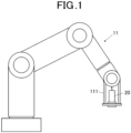
- An inkjet recording device 100 in this embodiment is, for example, an inkjet recording device that forms an image on a three-dimensional object or the like (recording medium), and includes a robot arm main body 11 that includes a carriage 111 mounted with inkjet heads 20 as shown in FIG. 1 .
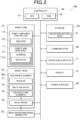
- FIG. 2 is a block diagram showing a functional configuration of the inkjet recording device 100 in this embodiment.
- the inkjet recording device 100 includes a robot arm 10, inkjet heads 20, a drive waveform signal generator 30, a controller 40, a storage 50, a communicator 60, an operation acceptor 71, a display 72, and a power supplier 80.
- the robot arm 10 includes: the robot arm main body 11 that includes the carriage 111; and a robot arm drive controller 12.
- the robot arm main body 11 is a 6-axis articulated robot.
- a recording medium is a three-dimensional object. It is configured that each inkjet head 20 can be arranged at a predetermined distance set with respect to an image formation surface of the recording medium even if the image formation surface is a curved surface.
- the robot arm main body 11 is not limited to a six-axis one. Alternatively, a multiple articulated robot that includes an appropriate number of axes, such as five axes or seven axes, may be adopted. Since a multiple robot itself is publicly known, the detailed description thereof is omitted.
- the robot arm drive controller 12 applies drive control to the robot arm main body 11 under control by the controller 40.
- the robot arm drive controller 12 includes an encoder 121.
- the encoder 121 detects the rotation of a drive motor of the robot arm drive controller 12, and outputs a signal in accordance with the rotation direction at every rotation by a predetermined angle, thus detecting the position of the carriage 111.
- the inkjet head 20 discharges ink on a recording medium, and records an image or the like.
- Each inkjet head 20 includes a plurality of recording elements 20a, and a head driver 24.
- the recording elements 20a each include nozzles 21, ink flow paths 22, and piezoelectric elements 23.
- the head driver 24 applies a drive signal (drive waveform) to a selected piezoelectric element 23, and causes the piezoelectric elements 23 to perform transforming operation.
- a drive signal drive waveform
- Ink is sent from a supply path common to the nozzles 21 to the nozzles 21 via ink flow paths 22 communicating with the respective nozzles 21.
- Each ink flow path 22 includes a pressure chamber.
- the piezoelectric elements 23 apply pressure variation in accordance with a drive waveform to ink supplied to the nozzles 21, eject (discharge) ink droplets from the nozzles 21, and record an image.
- the inkjet recording device 100 is provided with the inkjet heads 20 as many as the number of colors or types of ink ejected each time of image recording operation in the inkjet recording device 100.
- Each inkjet head 20 can discharge ink according to a multi-drop scheme that sequentially discharges a plurality of ink droplets, combines them at the middle as a single droplet, and lands this droplet in a corresponding pixel region (an identical pixel region), and can define a shading graduation in each pixel region in accordance with the number of ink droplets.
- the drive waveform signal generator 30 generates a drive waveform to be output by the head driver 24 to the recording elements 20a.
- the drive waveform signal generator 30 analog-converts digital data indicating a predefined drive waveform, and outputs a signal with amplified voltage and current, as a drive waveform, to the head driver 24.
- the generated drive waveform may include not only trapezoidal waves or rectangular waves for discharging ink, but also a drive waveform having a waveform that gradually changes in ink pressure (triangular waves or the like; the pulse width may be, for example, a half width (a width of a portion with 50% or more of amplitude); a value other than 50% may be adopted).
- the controller 40 is a processor that includes a CPU 41 (Central Processing Unit) and a RAM 42 (Random Access Memory), and comprehensively controls various operations of the inkjet recording device 100.
- the CPU 41 performs various operation processes, and executes a control operation.
- the RAM 42 provides the CPU 41 with a working memory space, and stores temporary data.
- the controller 40 controls output of the drive waveform pertaining to an ink discharge operation at each inkjet head 20 to the recording elements 20a, based on image data to be recorded and on setting data pertaining to image recording.
- the controller 40 stores a carriage coordinates and carriage speed table or a carriage coordinates and carriage acceleration table, described later, in the storage 50, thus setting at least one of the speed and the acceleration of the carriage 111, for each position of the carriage 111.
- the controller 40 functions as a setter.
- the controller 40 obtains, from the storage 50, a droplet speed and drive cycle characteristics table that is drive cycle dependency information on the droplet speed of ink discharged from the inkjet head 20. In this case, the controller 40 functions as an obtainer.
- the controller 40 corrects control parameters during discharge of ink from each inkjet head 20, based on at least one of the speed and the acceleration of the carriage 111, and on the drive cycle dependency information on the droplet speed. In this case, the controller 40 functions as a corrector.
- control parameters include image data, a discharge signal, and a drive waveform.
- the storage 50 stores the image data to be recorded, and stores various programs and the setting data.
- the storage 50 includes at least a nonvolatile memory, and may further include a volatile memory (RAM).
- the image data may be stored in the RAM.
- the nonvolatile memory is, for example, a flash memory or the like, and may alternatively or additionally include an HDD (Hard Disk Drive) or the like. Note that part of the storage 50 may be held by the inkjet heads 20 or the like. Parameter information unique to each inkjet head 20, initial abnormal nozzle information and the like can be stored in a nonvolatile memory included in each inkjet head 20. These pieces of information may be read by the controller 40 in initial setting or the like after the inkjet head 20 is attached to the inkjet recording device 100, and integrally stored and managed in the storage 50 of the inkjet recording device 100.
- the storage 50 stores the waveform setting data 51.
- the waveform setting data 51 stores waveform pattern data of the drive waveform to be output to each recording element 20a.
- the waveform pattern data stored here includes information on the start timing of the drive waveform, the pulse width, and the voltage amplitude associated with each time of ink discharge in a case in which multiple times of ink discharge are sequentially performed.
- the information on the pulse width may be a parameter obtained from the nonvolatile memory included in the inkjet head 20. These pieces may be digital data from which the drive waveform is generated by the drive waveform signal generator 30.
- the storage 50 stores the carriage coordinates and carriage speed table that indicates the correspondence relationship where the speed of the carriage 111 in the carriage coordinates indicating the predetermined position of the carriage 111 is preset.
- the carriage coordinates and carriage acceleration table indicating the correspondence relationship where the acceleration of the carriage 111 in the carriage coordinates is preset may be stored.
- the storage 50 stores the droplet speed and drive cycle characteristics table where the correspondence relationship between the droplet speed of ink discharged by the inkjet head 20 and the drive cycle of the inkjet head 20 is calculated by simulation.
- FIG. 3 shows an example of the drive cycle dependency of the ink droplet speed at the inkjet head 20. As shown in FIG. 3 , if the drive cycle of the inkjet head 20 is relatively short (e.g., 40 to 80 us), the ink droplet speed is unstable.
- the communicator 60 controls execution of communication with external devices. For example, based on a communication standard, such as TCP/IP, the communicator 60 can be connected to an external computer, obtain job data including image data to be recorded, and output a status of the image recording operation based on the job data.
- the communicator 60 may be directly connected to a peripheral device by the USB (Universal Serial Bus) or the like, thus allowing data to be transmitted and received.
- USB Universal Serial Bus
- the operation acceptor 71 accepts an input operation by a user or the like, and outputs the accepted content, as an input signal, to the controller 40.
- the operation acceptor 71 includes, for example, a touch panel, and press button switches.
- the touch panel is positioned to overlap a display screen of the display 72, and may allow operation content to be indicated in synchronization with the display content on the display screen.
- the display 72 displays a status, a selection menu and the like, for the user or the like.
- the display 72 includes, for example, the display screen, and indicators (lamps).
- the display 72 includes, for example, a liquid crystal display, and can display various characters and diagrams on the display screen in a dot matrix manner.
- the indicators are made up of, for example, LED lamps or the like, and may be used in a case of indicating presence or absence of power supply, presence or absence of operation abnormality or the like.
- the power supplier 80 supplies power at a voltage in accordance with each component of the inkjet recording device 100.
- a voltage in accordance with the peak voltage of each drive waveform is output to a drive board of the inkjet head 20.
- control parameter correction process in the inkjet head 20 of the inkjet recording device 100 in this embodiment is described.
- the controller 40 executes the control parameter correction process in this embodiment before image formation by the inkjet head 20.
- FIG. 4 is a flowchart showing the flow of the control parameter correction process.
- the controller 40 obtains the carriage coordinates and carriage speed table from the storage 50 (Step S1).
- the controller 40 obtains the droplet speed and drive cycle characteristics table from the storage 50 (Step S2).
- the controller 40 calculates a carriage coordinates and droplet speed table indicating the correspondence relationship between the carriage coordinates and the ink droplet speed, from the carriage coordinates and carriage speed table obtained in Step S1 and the droplet speed and drive cycle characteristics table obtained in Step S2 (Step S3).
- the controller 40 calculates a shading density profile indicating the correspondence relationship between the carriage coordinates and the shading of an image to be formed as shown in FIG. 5A , based on the carriage coordinates and droplet speed table calculated in Step S3 (Step S4).
- the controller 40 calculates a shading correction profile shown in FIG. 5B for canceling out the shading unevenness of the shading density profile calculated in Step S4 (Step S5).
- the example in FIGS. 5A and 5B is in a case of what is called solid printing and is for discharge on every pixel.
- Step S6 the controller 40 corrects the shading of the image data to be recorded (control parameters), based on the shading correction profile calculated in Step S5 (Step S6), and finishes the processing.
- controller 40 may execute the control parameter correction process using the carriage coordinates and carriage acceleration table instead of the carriage coordinates and carriage speed table.
- the carriage 111 includes a detector 111a.
- the detector 111a is a sensor that detects at least one of the speed and the acceleration of the carriage 111, and outputs a detected signal to the controller 40.
- the detector 111a may be included in the inkjet head 20.
- the detector 111a is included in the carriage 111 or the inkjet head 20 as described above. Accordingly, the speed and the acceleration of the inkjet head 20 can be more correctly detected than a case in which the detector 111a is included in a portion of the robot arm main body 11 other than the carriage 111.
- the controller 40 executes the control parameter correction process in this embodiment during image formation by the inkjet head 20.
- FIG. 6 is a flowchart showing the flow of a control parameter correction process according to this embodiment.
- the controller 40 obtains current position information on the carriage 111, from the encoder 121 (Step S11).
- the controller 40 obtains, from the detector 111a, the average VH N of the speed of the carriage 111 at the pixel corresponding to the current position of the carriage 111 obtained in Step S 11 (Step S12).
- the average of the speed of the carriage 111 at the pixel corresponding to the current position is the average of the speed when the inkjet head 20 passes from the (N-1)-th pixel where discharge has been performed to the N-th pixel where next discharge is to be performed, for example.
- the controller 40 calculates the drive cycle T N at the pixel (e.g., (N-1)-th pixel to N-th pixel) corresponding to the current position, based on the average VH N of the speed of the carriage 111 at the pixel corresponding to the current position obtained in Step S12, according to the following Expression (1) (Step S13).
- T N d N / VH N
- d N denotes the distance from the (N-1)-th pixel to the N-th pixel in input image data.
- the controller 40 obtains the droplet speed and drive cycle characteristics table from the storage 50 (Step S14).
- the controller 40 obtains the droplet speed DV N at the pixel corresponding to the current position, based on the drive cycle T N at the pixel corresponding to the current position calculated in Step S13, and the droplet speed and drive cycle characteristics table obtained in Step S14 (Step S15).
- the controller 40 calculates the droplet flight time t N at the pixel corresponding to the current position, based on the droplet speed DV N obtained in Step S 15, and the distance Gap from the nozzle surface of the inkjet head 20 to the image formation surface of the recording medium, according to the following Expression (2) (Step S16).
- t N Gap / DV N
- the controller 40 calculates the position at which an ink droplet is to land on the image formation surface, based on the droplet flight time t N calculated in Step S16 and the average VH N of the speed of the carriage 111 at the pixel corresponding to the current position, thus calculating the distance D N between adjacent dots at the pixel corresponding to the current position, according to the following Expression (3) (Step S17).
- D N VH N ⁇ t N ⁇ VH N ⁇ 1 ⁇ t N ⁇ 1 + d N
- FIG. 7 shows an example of the variation in distance D N between adjacent dots.
- the abscissa axis indicates the position (mm) of the carriage 111
- the ordinate axis indicates the variation (um) in distance D N between adjacent dots.
- the controller 40 calculates a shading correction value such that the distance D N between adjacent dots calculated in Step S17 can be equal to the distance d N from the (N-1)-th pixel to the N-th pixel in the input image data (a target value in a state without shading unevenness) (Step S18). Specifically, if the distance D N between adjacent dots is smaller than the distance d N , correction in a direction of reducing the shading is made. If it is greater, correction in a direction of increasing the shading is made.
- controller 40 corrects the shading of the image data to be recorded (control parameter), based on the shading correction value calculated in Step S18 (Step S19), and finishes the processing.
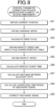
- FIG. 8 is a flowchart showing the control parameter correction process in this modification example.
- the controller 40 executes the control parameter correction process in this modification example during image formation by the inkjet head 20.
- the configuration of the inkjet recording device 100 in this modification example is the same as that of the inkjet recording device 100 in the second embodiment.
- the controller 40 executes Steps S21 to S27 similar to Steps S11 to S17 of the control parameter correction process in the second embodiment.
- the controller 40 executes correction of an ink discharge signal such that the distance D N between adjacent dots calculated in Step S27 can be equal to the distance d N from the (N-1)-th pixel to the N-th pixel in the input image data (the target value in the state without shading unevenness). Specifically, the controller 40 calculates the correction time period ⁇ ta N of the discharge signal so as to satisfy the following Expression (4), according to the following Expression (5) (Step S28).
- VH N ⁇ ta N is the average VH N of the speed of the inkjet head 20 passing the N-th pixel at which next discharge is to be performed, and the amount of deviation of the droplet landing position due to signal correction in a case in which the inkjet head 20 is moving.
- the controller 40 corrects the discharge signal (control parameter), based on the correction time period ⁇ ta N of the discharge signal calculated in Step S28 (Step S29), and finishes the processing.
- FIG. 9 shows an example of the correction time period ⁇ ta N of the discharge signal.
- the abscissa axis indicates the position (mm) of the carriage 111
- the ordinate axis indicates the correction time period ⁇ ta N (us) of the discharge signal.
- the time period of applying the discharge signal is corrected to be minus (in a direction of increasing the drive frequency). If the variation in distance D N between adjacent dots is smaller, the time period of applying the discharge signal corrected to be plus (in a direction of reducing the drive frequency).
- FIGS. 7 and 9 is in a case of what is called solid printing and is for discharge on every pixel.
- the discharge is discontinuous unlike the case shown in FIGS. 7 and 9 in which the discharge is continuous.
- the controller 40 executes the control parameter correction process during image formation by the inkjet head 20.
- All the pixels may be corrected before image formation.
- correction is performed with reference to the (N-1)-th pixel, based on the amount of deviation of the droplet landing positions from the (N-1)-th pixel to the N-th pixel.
- correction may be performed with reference to the 0-th pixel, based on the amount of deviation of droplet landing position therefrom.
- FIG. 10 is a flowchart showing the control parameter correction process in this modification example.
- the controller 40 executes the control parameter correction process in this modification example during image formation by the inkjet head 20.
- the configuration of the inkjet recording device 100 in this modification example is the same as that of the inkjet recording device 100 in the second embodiment.
- the controller 40 executes Steps S31 to S35 similar to Steps S11 to S15 of the control parameter correction process in the second embodiment.
- the controller 40 selects waveform pattern data (control parameter) of the drive waveform to be output to each recording elements 20a, from the waveform setting data 51, based on the droplet speed obtained in Step S35 (Step S36), and finishes the processing. Specifically, as shown in FIG. 11 , if the droplet speed is slower than the target value in the state without shading unevenness, the controller 40 selects a waveform A having a low voltage value. If the droplet speed is higher than the target value, the controller 40 selects a waveform C having a high voltage value. If the droplet speed is appropriate with respect to the target value, the controller 40 selects a waveform B having a voltage value between the values of the waveforms A and C.
- the deviation in the landing position before and after switching of the waveform pattern can be small.
- Step S36 in the control parameter correction process in the modification example 2 of the second embodiment described above the voltage value of the drive waveform is changed by selecting the waveform pattern data of the drive waveform on the basis of the droplet speed.
- the pulse width of the drive waveform or the slope time period may be changed.
- the shape of the waveform may be a complicated waveform that is not a waveform with a single pulse.
- the number of waveform pattern data items of the drive waveform stored in the waveform setting data 51 is determined based on the maximum frequency of an image formation job, the transfer rate of input image data, the number of gradations of ink quantity.
- FIG. 12 is a flowchart showing the control parameter correction process in this modification example.
- the controller 40 executes the control parameter correction process in this modification example during image formation by the inkjet head 20.
- the configuration of the inkjet recording device 100 in this modification example is the same as that of the inkjet recording device 100 in the second embodiment.
- the controller 40 executes Steps S41 to S45 similar to Steps S11 to S15 of the control parameter correction process in the second embodiment.
- the controller 40 controls the robot arm drive controller 12, based on the droplet speed obtained in Step S45, and changes at least one of the position and angle of the carriage 111 (Step S46), and finishes the processing. Specifically, if the droplet speed is lower than the target value in the state without shading unevenness (predetermined reference value), the controller 40 reduces the distance between the carriage 111 and the recording medium (control parameter). If the droplet speed is higher than the target value, the controller 40 increases the distance between the carriage 111 and the recording medium (control parameter).
- the controller 40 corrects the angle of the carriage 111 (control parameter) so as to make the droplet landing positions dense. If the droplet speed is higher than the target value, the controller 40 corrects the angle of the carriage 111 (control parameter) so as to make the droplet landing positions sparse.
- the controller 40 may obtain, from the detector 111a, the acceleration of the carriage 111 at the pixel corresponding to the current position of the carriage 111, and execute the control parameter correction process, based on the acceleration of the carriage 111.
- the inkjet recording device 100 includes: an inkjet head 20; a carriage 111 mounted with the inkjet head 20; a setter (controller 40) that sets at least one of a speed and an acceleration of the carriage 111, for each position of the carriage 111; an obtainer (controller 40) that obtains drive cycle dependency information on a droplet speed of ink discharged from the inkjet head 20; and a corrector (controller 40) that corrects a control parameter during discharge of ink from the inkjet head 20, based on at least one of the speed and the acceleration of the carriage, and on the drive cycle dependency information on the droplet speed.
- the inkjet recording device 100 includes: an inkjet head 20; a carriage 111 mounted with the inkjet head 20; a detector 111a that detects at least one of a speed and an acceleration of the carriage 111, for each pixel of an image to be formed; an obtainer (controller 40) that obtains drive cycle dependency information on a droplet speed of ink discharged from the inkjet head 20; and a corrector (controller 40) that corrects a control parameter during discharge of ink from the inkjet head 20, based on at least one of the speed and the acceleration of the carriage 111, and on the drive cycle dependency information on the droplet speed.
- the inkjet recording device 100 includes: an inkjet head 20; a carriage 111 mounted with the inkjet head 20; a setter (controller 40) that sets at least one of a speed and an acceleration of the carriage, for each position of the carriage 111; a detector 111a that detects at least one of the speed and the acceleration of the carriage 111, for each pixel of an image to be formed; an obtainer (controller 40) that obtains drive cycle dependency information on a droplet speed of ink discharged from the inkjet head 20; and a corrector (controller 40) that corrects a control parameter during discharge of ink from the inkjet head 20, based on at least one of the speed and the acceleration of the carriage 111, and on the drive cycle dependency information on the droplet speed.
- the inkjet recording device 100 in this embodiment includes the detector 111a, in the inkjet head 20 or the carriage 111.
- the speed and the acceleration of the inkjet head 20 can be more correctly detected than a case in which the detector 111a is included in a portion of the robot arm main body 11 other than the carriage 111.
- the corrector corrects the control parameters.
- the inkjet recording device 100 in this embodiment adopts a three-dimensional object as an image formation target.
- the corrector corrects image data as the control parameter.
- the corrector corrects the discharge signal as the control parameter.
- the corrector corrects the control parameter through selection of a drive waveform.
- the corrector corrects a distance between the inkjet head 20 and a recording medium, and an angle of the inkjet head 20 from the recording medium, as the control parameters.
- the corrector corrects the distance between the inkjet head 20 and the recording medium in a widening direction when the droplet speed is higher than a predetermined reference value, and corrects the distance in a narrowing direction when the droplet speed is lower than the predetermined reference value.
- the corrector corrects the angle of the inkjet head 20 from the recording medium so that landing positions of droplets discharged from the inkjet head 20 can be sparse when the droplet speed is higher than the predetermined reference value, and corrects the angle so that the landing positions of droplets discharged from the inkjet head 20 can be dense when the droplet speed is lower than the predetermined reference value.
- the inkjet recording device 100 in this embodiment includes the robot arm (robot arm main body 11), and the robot arm includes the carriage 111.
- the carriage 111 is thus included in the robot arm, and if the speed of the carriage 111 is not a constant speed, a more stable image quality in the formed image can be achieved.
- the inkjet recording device 100 includes the robot arm main body 11 mounted with the inkjet head 20.
- the robot arm main body 11 mounted with the inkjet head 20.
- It may be configured to correct the control parameter during ink discharge from the inkjet head 20 in the case in which the inkjet head 20 is configured to be included in the carriage moving on a rail, and an image is formed when the carriage moving speed is not a constant speed.
- correction in the case in which the speed of the carriage is not a constant speed are described.
- Correction may be performed when the speed of the carriage is a constant speed but the drive frequency of the inkjet head varies.
- the speed and the acceleration of the carriage 111 are detected by the detector included in the inkjet head 20 or the carriage 111.
- Detection may be performed based on the output signal of the encoder 121 of the robot arm drive controller 12.
- the controller 40 may use, in a combined manner, the modes of correcting the control parameters of the inkjet head 20 during ink discharge in the control parameter correction process of the first and second embodiments described above.
- the present invention is applicable to an inkjet recording device, and a program.
Landscapes
- Engineering & Computer Science (AREA)
- Manufacturing & Machinery (AREA)
- Ink Jet (AREA)
Abstract
Description
- The present invention relates to an inkjet recording device, and a program.
- There is an inkjet recording device that applies a pressure variation to ink supplied through an ink flow path (ink channel), in pressure chambers positioned at the middle of the ink channel, and discharges ink through multiple nozzles that communicate with the pressure chambers, thus recording an image, a thin film, wiring, a three-dimensional structure, etc.
- The inkjet recording device drives an inkjet head while causing a carriage mounted with the inkjet head to perform scanning on a conveyance axis, thus discharging droplets of ink and forming an image on a recording medium. The drive cycle of the inkjet head is generated based on an output signal obtained from a linear encoder in synchronization with scanning by the carriage.
- In relation to this,
Patent Literature 1 describes an invention that dynamically changes the timing of pulses for driving a printing head, based on the speed and acceleration of the carriage. - Patent Literature 1:
JP 2002-002046A - As described above, based on the position information on the carriage, the drive cycle of the inkjet is determined. Accordingly, when the conveyance speed of the inkjet head is not a constant speed, the drive cycle and the drive frequency of the inkjet head vary. After droplets are discharged, reverberation occurs in a pressure chamber of the inkjet head, and affects droplets to be discharged next and thereafter. Consequently, when the drive frequency of the inkjet head varies, the affecting degree by the reverberant also varies. Accordingly, the droplet speed of ink also varies. There has been a problem that possible variation in ink droplet speed varies droplet landing positions, and shading unevenness occurs in a formed image.
-
FIG. 13 shows an example of the drive cycle of the inkjet head, and the droplet speed of ink when the conveyance speed of the inkjet head is not a constant speed. In the example shown inFIG. 13 , the abscissa axis indicates time (s) after start of driving the inkjet head, and the ordinate axis indicates the conveyance speed (m/s: solid line) of the inkjet head, and the drive cycle (µs: broken line) of the inkjet head, and the ink droplet speed (m/s: chain line) are shown. In a period in which driving of the inkjet head is started and the inkjet head is in acceleration, the drive cycle of the inkjet head gradually decreases. The ink droplet speed is unstable and periodically varies, and the amplitude gradually increases. - According to the invention according to
Patent Literature 1, variation in droplet landing position due to variation in drive frequency (cycle) of the inkjet head is not compensated, and the problem described above is not solved. - The present invention has an object to provide an inkjet recording device and a program that can achieve a more stable image quality in a formed image.
- To achieve the object described above, an inkjet recording device of an invention according to
claim 1, includes: - an inkjet head;
- a carriage mounted with the inkjet head;
- a setter that sets at least one of a speed and an acceleration of the carriage, for each position of the carriage;
- an obtainer that obtains drive cycle dependency information on a droplet speed of ink discharged from the inkjet head; and
- a corrector that corrects a control parameter during discharge of ink from the inkjet head, based on at least one of the speed and the acceleration of the carriage, and on the drive cycle dependency information on the droplet speed.
- An inkjet recording device of an invention according to
claim 2, includes: - an inkjet head;
- a carriage mounted with the inkjet head;
- a detector that detects at least one of a speed and an acceleration of the carriage, for each pixel of an image to be formed;
- an obtainer that obtains drive cycle dependency information on a droplet speed of ink discharged from the inkjet head; and
- a corrector that corrects a control parameter during discharge of ink from the inkjet head, based on at least one of the speed and the acceleration of the carriage, and on the drive cycle dependency information on the droplet speed.
- An inkjet recording device of an invention according to
claim 3, includes: - an inkjet head;
- a carriage mounted with the inkjet head;
- a setter that sets at least one of a speed and an acceleration of the carriage, for each position of the carriage;
- a detector that detects at least one of the speed and the acceleration of the carriage, for each pixel of an image to be formed;
- an obtainer that obtains drive cycle dependency information on a droplet speed of ink discharged from the inkjet head; and
- a corrector that corrects a control parameter during discharge of ink from the inkjet head, based on at least one of the speed and the acceleration of the carriage, and on the drive cycle dependency information on the droplet speed.
- The invention according to claim 4 is the inkjet recording device according to
claim
wherein the detector is included in the inkjet head, or the carriage. - The invention according to
claim 5 is the inkjet recording device according to any one ofclaims 1 to 4,
wherein when the speed of the carriage is not a constant speed, the corrector corrects the control parameter. - The invention according to
claim 6 is the inkjet recording device according to any one ofclaims 1 to 5,
wherein a three-dimensional object is an image formation target. - The invention according to
claim 7 is the inkjet recording device according to any one ofclaims 1 to 6,
wherein the corrector corrects image data as the control parameter. - The invention according to
claim 8 is the inkjet recording device according to any one ofclaims 1 to 6,
wherein the corrector corrects a discharge signal as the control parameter. - The invention according to claim 9 is the inkjet recording device according to any one of
claims 1 to 6,
wherein the corrector corrects the control parameter through selection of a drive waveform. - The invention according to
claim 10 is the inkjet recording device according to any one ofclaims 1 to 9,
wherein the corrector corrects a distance between the inkjet head and a recording medium, and an angle of the inkjet head from the recording medium, as the control parameter. - The invention according to
claim 11 is the inkjet recording device according toclaim 10,
wherein the corrector corrects the distance between the inkjet head and the recording medium in a widening direction when the droplet speed is higher than a predetermined reference value, and corrects the distance in a narrowing direction when the droplet speed is lower than the predetermined reference value. - The invention according to
claim 12 is the inkjet recording device according toclaim
wherein the corrector corrects the angle of the inkjet head from the recording medium so that landing positions of droplets discharged from the inkjet head can be sparse when the droplet speed is higher than a predetermined reference value, and corrects the angle so that the landing positions of droplets discharged from the inkjet head can be dense when the droplet speed is lower than the predetermined reference value. - The invention according to
claim 13 is the inkjet recording device according to any one ofclaims 1 to 12, further comprises - a robot arm,
- wherein the robot arm includes the carriage.
- A program of an invention according to claim 14 causes a computer of an inkjet recording device including:
an inkjet head; and a carriage mounted with the inkjet head, to function as: - a setter that sets at least one of a speed and an acceleration of the carriage, for each position of the carriage;
- an obtainer that obtains drive cycle dependency information on a droplet speed of ink discharged from the inkjet head; and
- a corrector that corrects a control parameter during discharge of ink from the inkjet head, based on at least one of the speed and the acceleration of the carriage, and on the drive cycle dependency information on the droplet speed.
- According to the present invention, in a formed image, a more stable image quality can be achieved.
-
- [
FIG. 1] FIG. 1 shows an example of a robot arm that includes a carriage mounted with an inkjet head in this embodiment. - [
FIG. 2] FIG. 2 is a block diagram showing a functional configuration of an inkjet recording device in this embodiment. - [
FIG. 3] FIG. 3 shows an example of drive cycle dependency of the droplet speed. - [
FIG. 4] FIG. 4 is a flowchart of a control parameter correction process according to a first embodiment. - [
FIG. 5A] FIG. 5A shows an example of a shading density profile. - [
FIG. 5B] FIG. 5B shows an example of a shading correction profile. - [
FIG. 6] FIG. 6 is a flowchart of a control parameter correction process according to a second embodiment. - [
FIG. 7] FIG. 7 shows an example of a variation in distance between adjacent dots. - [
FIG. 8] FIG. 8 is a flowchart of a control parameter correction process according to a modification example 1 of the second embodiment. - [
FIG. 9] FIG. 9 shows an example of the correction time period of a discharge signal. - [
FIG. 10] FIG. 10 is a flowchart of a control parameter correction process according to a modification example 2 of the second embodiment. - [
FIG. 11] FIG. 11 shows an example of waveform patterns of drive waveforms. - [
FIG. 12] FIG. 12 is a flowchart of a control parameter correction process according to a modification example 3 of the second embodiment. - [
FIG. 13] FIG. 13 shows an example of the conveyance speed, drive cycle, and ink droplet speed of the inkjet head. - Hereinafter, embodiments of the present invention are described with reference to the drawings.
- An
inkjet recording device 100 in this embodiment is, for example, an inkjet recording device that forms an image on a three-dimensional object or the like (recording medium), and includes a robot armmain body 11 that includes acarriage 111 mounted with inkjet heads 20 as shown inFIG. 1 . -
FIG. 2 is a block diagram showing a functional configuration of theinkjet recording device 100 in this embodiment. - The
inkjet recording device 100 includes arobot arm 10, inkjet heads 20, a drivewaveform signal generator 30, acontroller 40, astorage 50, acommunicator 60, anoperation acceptor 71, adisplay 72, and apower supplier 80. - The
robot arm 10 includes: the robot armmain body 11 that includes thecarriage 111; and a robotarm drive controller 12. - The robot arm
main body 11 is a 6-axis articulated robot. For example, a recording medium is a three-dimensional object. It is configured that eachinkjet head 20 can be arranged at a predetermined distance set with respect to an image formation surface of the recording medium even if the image formation surface is a curved surface. The robot armmain body 11 is not limited to a six-axis one. Alternatively, a multiple articulated robot that includes an appropriate number of axes, such as five axes or seven axes, may be adopted. Since a multiple robot itself is publicly known, the detailed description thereof is omitted. - The robot
arm drive controller 12 applies drive control to the robot armmain body 11 under control by thecontroller 40. - The robot
arm drive controller 12 includes anencoder 121. Theencoder 121 detects the rotation of a drive motor of the robotarm drive controller 12, and outputs a signal in accordance with the rotation direction at every rotation by a predetermined angle, thus detecting the position of thecarriage 111. - The
inkjet head 20 discharges ink on a recording medium, and records an image or the like. Eachinkjet head 20 includes a plurality ofrecording elements 20a, and ahead driver 24. - The
recording elements 20a each includenozzles 21,ink flow paths 22, andpiezoelectric elements 23. - The
head driver 24 applies a drive signal (drive waveform) to a selectedpiezoelectric element 23, and causes thepiezoelectric elements 23 to perform transforming operation. - Ink is sent from a supply path common to the
nozzles 21 to thenozzles 21 viaink flow paths 22 communicating with therespective nozzles 21. Eachink flow path 22 includes a pressure chamber. By transforming operation in accordance with application of a drive voltage to thepiezoelectric elements 23 that are positioned along a wall surface of the pressure chamber (or are the wall surface itself), pressure variation is applied to ink in the pressure chamber. Thepiezoelectric elements 23 apply pressure variation in accordance with a drive waveform to ink supplied to thenozzles 21, eject (discharge) ink droplets from thenozzles 21, and record an image. Theinkjet recording device 100 is provided with the inkjet heads 20 as many as the number of colors or types of ink ejected each time of image recording operation in theinkjet recording device 100. Eachinkjet head 20 can discharge ink according to a multi-drop scheme that sequentially discharges a plurality of ink droplets, combines them at the middle as a single droplet, and lands this droplet in a corresponding pixel region (an identical pixel region), and can define a shading graduation in each pixel region in accordance with the number of ink droplets. - The drive
waveform signal generator 30 generates a drive waveform to be output by thehead driver 24 to therecording elements 20a. Although not specifically limited, the drivewaveform signal generator 30 analog-converts digital data indicating a predefined drive waveform, and outputs a signal with amplified voltage and current, as a drive waveform, to thehead driver 24. The generated drive waveform may include not only trapezoidal waves or rectangular waves for discharging ink, but also a drive waveform having a waveform that gradually changes in ink pressure (triangular waves or the like; the pulse width may be, for example, a half width (a width of a portion with 50% or more of amplitude); a value other than 50% may be adopted). - The
controller 40 is a processor that includes a CPU 41 (Central Processing Unit) and a RAM 42 (Random Access Memory), and comprehensively controls various operations of theinkjet recording device 100. TheCPU 41 performs various operation processes, and executes a control operation. TheRAM 42 provides theCPU 41 with a working memory space, and stores temporary data. Thecontroller 40 controls output of the drive waveform pertaining to an ink discharge operation at eachinkjet head 20 to therecording elements 20a, based on image data to be recorded and on setting data pertaining to image recording. - The
controller 40 stores a carriage coordinates and carriage speed table or a carriage coordinates and carriage acceleration table, described later, in thestorage 50, thus setting at least one of the speed and the acceleration of thecarriage 111, for each position of thecarriage 111. In this case, thecontroller 40 functions as a setter. - The
controller 40 obtains, from thestorage 50, a droplet speed and drive cycle characteristics table that is drive cycle dependency information on the droplet speed of ink discharged from theinkjet head 20. In this case, thecontroller 40 functions as an obtainer. - The
controller 40 corrects control parameters during discharge of ink from eachinkjet head 20, based on at least one of the speed and the acceleration of thecarriage 111, and on the drive cycle dependency information on the droplet speed. In this case, thecontroller 40 functions as a corrector. - Here, the control parameters include image data, a discharge signal, and a drive waveform.
- The
storage 50 stores the image data to be recorded, and stores various programs and the setting data. Thestorage 50 includes at least a nonvolatile memory, and may further include a volatile memory (RAM). The image data may be stored in the RAM. The nonvolatile memory is, for example, a flash memory or the like, and may alternatively or additionally include an HDD (Hard Disk Drive) or the like. Note that part of thestorage 50 may be held by the inkjet heads 20 or the like. Parameter information unique to eachinkjet head 20, initial abnormal nozzle information and the like can be stored in a nonvolatile memory included in eachinkjet head 20. These pieces of information may be read by thecontroller 40 in initial setting or the like after theinkjet head 20 is attached to theinkjet recording device 100, and integrally stored and managed in thestorage 50 of theinkjet recording device 100. - The
storage 50 stores thewaveform setting data 51. - The
waveform setting data 51 stores waveform pattern data of the drive waveform to be output to eachrecording element 20a. In particular, the waveform pattern data stored here includes information on the start timing of the drive waveform, the pulse width, and the voltage amplitude associated with each time of ink discharge in a case in which multiple times of ink discharge are sequentially performed. The information on the pulse width may be a parameter obtained from the nonvolatile memory included in theinkjet head 20. These pieces may be digital data from which the drive waveform is generated by the drivewaveform signal generator 30. - The
storage 50 stores the carriage coordinates and carriage speed table that indicates the correspondence relationship where the speed of thecarriage 111 in the carriage coordinates indicating the predetermined position of thecarriage 111 is preset. Instead of the carriage coordinates and carriage speed table, the carriage coordinates and carriage acceleration table indicating the correspondence relationship where the acceleration of thecarriage 111 in the carriage coordinates is preset may be stored. - The
storage 50 stores the droplet speed and drive cycle characteristics table where the correspondence relationship between the droplet speed of ink discharged by theinkjet head 20 and the drive cycle of theinkjet head 20 is calculated by simulation. Here,FIG. 3 shows an example of the drive cycle dependency of the ink droplet speed at theinkjet head 20. As shown inFIG. 3 , if the drive cycle of theinkjet head 20 is relatively short (e.g., 40 to 80 us), the ink droplet speed is unstable. - The
communicator 60 controls execution of communication with external devices. For example, based on a communication standard, such as TCP/IP, thecommunicator 60 can be connected to an external computer, obtain job data including image data to be recorded, and output a status of the image recording operation based on the job data. Thecommunicator 60 may be directly connected to a peripheral device by the USB (Universal Serial Bus) or the like, thus allowing data to be transmitted and received. - The
operation acceptor 71 accepts an input operation by a user or the like, and outputs the accepted content, as an input signal, to thecontroller 40. Theoperation acceptor 71 includes, for example, a touch panel, and press button switches. The touch panel is positioned to overlap a display screen of thedisplay 72, and may allow operation content to be indicated in synchronization with the display content on the display screen. - The
display 72 displays a status, a selection menu and the like, for the user or the like. Thedisplay 72 includes, for example, the display screen, and indicators (lamps). Thedisplay 72 includes, for example, a liquid crystal display, and can display various characters and diagrams on the display screen in a dot matrix manner. The indicators are made up of, for example, LED lamps or the like, and may be used in a case of indicating presence or absence of power supply, presence or absence of operation abnormality or the like. - The
power supplier 80 supplies power at a voltage in accordance with each component of theinkjet recording device 100. A voltage in accordance with the peak voltage of each drive waveform is output to a drive board of theinkjet head 20. - Next, a control parameter correction process in the
inkjet head 20 of theinkjet recording device 100 in this embodiment is described. Thecontroller 40 executes the control parameter correction process in this embodiment before image formation by theinkjet head 20. -
FIG. 4 is a flowchart showing the flow of the control parameter correction process. - First, the
controller 40 obtains the carriage coordinates and carriage speed table from the storage 50 (Step S1). - Next, the
controller 40 obtains the droplet speed and drive cycle characteristics table from the storage 50 (Step S2). - Next, the
controller 40 calculates a carriage coordinates and droplet speed table indicating the correspondence relationship between the carriage coordinates and the ink droplet speed, from the carriage coordinates and carriage speed table obtained in Step S1 and the droplet speed and drive cycle characteristics table obtained in Step S2 (Step S3). - Next, the
controller 40 calculates a shading density profile indicating the correspondence relationship between the carriage coordinates and the shading of an image to be formed as shown inFIG. 5A , based on the carriage coordinates and droplet speed table calculated in Step S3 (Step S4). - Next, the
controller 40 calculates a shading correction profile shown inFIG. 5B for canceling out the shading unevenness of the shading density profile calculated in Step S4 (Step S5). Here, the example inFIGS. 5A and 5B is in a case of what is called solid printing and is for discharge on every pixel. - Next, the
controller 40 corrects the shading of the image data to be recorded (control parameters), based on the shading correction profile calculated in Step S5 (Step S6), and finishes the processing. - Here, the
controller 40 may execute the control parameter correction process using the carriage coordinates and carriage acceleration table instead of the carriage coordinates and carriage speed table. - In the
inkjet recording device 100 in this embodiment, thecarriage 111 includes adetector 111a. Thedetector 111a is a sensor that detects at least one of the speed and the acceleration of thecarriage 111, and outputs a detected signal to thecontroller 40. Thedetector 111a may be included in theinkjet head 20. Thedetector 111a is included in thecarriage 111 or theinkjet head 20 as described above. Accordingly, the speed and the acceleration of theinkjet head 20 can be more correctly detected than a case in which thedetector 111a is included in a portion of the robot armmain body 11 other than thecarriage 111. - The other points of configuration are the same as those of the configuration in the first embodiment.
- Next, a control parameter correction process in the
inkjet head 20 of theinkjet recording device 100 in this embodiment is described. Thecontroller 40 executes the control parameter correction process in this embodiment during image formation by theinkjet head 20. -
FIG. 6 is a flowchart showing the flow of a control parameter correction process according to this embodiment. - First, the
controller 40 obtains current position information on thecarriage 111, from the encoder 121 (Step S11). - Next, the
controller 40 obtains, from thedetector 111a, the average VHN of the speed of thecarriage 111 at the pixel corresponding to the current position of thecarriage 111 obtained in Step S 11 (Step S12). Here, the average of the speed of thecarriage 111 at the pixel corresponding to the current position is the average of the speed when theinkjet head 20 passes from the (N-1)-th pixel where discharge has been performed to the N-th pixel where next discharge is to be performed, for example. - Next, the
controller 40 calculates the drive cycle TN at the pixel (e.g., (N-1)-th pixel to N-th pixel) corresponding to the current position, based on the average VHN of the speed of thecarriage 111 at the pixel corresponding to the current position obtained in Step S12, according to the following Expression (1) (Step S13).
- Here, dN denotes the distance from the (N-1)-th pixel to the N-th pixel in input image data.
- Next, the
controller 40 obtains the droplet speed and drive cycle characteristics table from the storage 50 (Step S14). - Next, the
controller 40 obtains the droplet speed DVN at the pixel corresponding to the current position, based on the drive cycle TN at the pixel corresponding to the current position calculated in Step S13, and the droplet speed and drive cycle characteristics table obtained in Step S14 (Step S15). - Next, the
controller 40 calculates the droplet flight time tN at the pixel corresponding to the current position, based on the droplet speed DVN obtained inStep S 15, and the distance Gap from the nozzle surface of theinkjet head 20 to the image formation surface of the recording medium, according to the following Expression (2) (Step S16).
- Here, when the droplet flight time tN is calculated, the effect of air resistance to ink droplets may be considered.
- Next, the
controller 40 calculates the position at which an ink droplet is to land on the image formation surface, based on the droplet flight time tN calculated in Step S16 and the average VHN of the speed of thecarriage 111 at the pixel corresponding to the current position, thus calculating the distance DN between adjacent dots at the pixel corresponding to the current position, according to the following Expression (3) (Step S17).
-
FIG. 7 shows an example of the variation in distance DN between adjacent dots. In the example shown inFIG. 7 , the abscissa axis indicates the position (mm) of thecarriage 111, and the ordinate axis indicates the variation (um) in distance DN between adjacent dots. - Next, the
controller 40 calculates a shading correction value such that the distance DN between adjacent dots calculated in Step S17 can be equal to the distance dN from the (N-1)-th pixel to the N-th pixel in the input image data (a target value in a state without shading unevenness) (Step S18). Specifically, if the distance DN between adjacent dots is smaller than the distance dN, correction in a direction of reducing the shading is made. If it is greater, correction in a direction of increasing the shading is made. - Next, the
controller 40 corrects the shading of the image data to be recorded (control parameter), based on the shading correction value calculated in Step S18 (Step S19), and finishes the processing. - Next, a modification example 1 of the second embodiment is described.
-
FIG. 8 is a flowchart showing the control parameter correction process in this modification example. Thecontroller 40 executes the control parameter correction process in this modification example during image formation by theinkjet head 20. - Hereinafter, the difference from the second embodiment is mainly described. The configuration of the
inkjet recording device 100 in this modification example is the same as that of theinkjet recording device 100 in the second embodiment. - In the control parameter correction process in this modification example shown in
FIG. 8 , first, thecontroller 40 executes Steps S21 to S27 similar to Steps S11 to S17 of the control parameter correction process in the second embodiment. - Next, the
controller 40 executes correction of an ink discharge signal such that the distance DN between adjacent dots calculated in Step S27 can be equal to the distance dN from the (N-1)-th pixel to the N-th pixel in the input image data (the target value in the state without shading unevenness). Specifically, thecontroller 40 calculates the correction time period ΔtaN of the discharge signal so as to satisfy the following Expression (4), according to the following Expression (5) (Step S28).

- Here, VHN·ΔtaN is the average VHN of the speed of the
inkjet head 20 passing the N-th pixel at which next discharge is to be performed, and the amount of deviation of the droplet landing position due to signal correction in a case in which theinkjet head 20 is moving. - Next, the
controller 40 corrects the discharge signal (control parameter), based on the correction time period ΔtaN of the discharge signal calculated in Step S28 (Step S29), and finishes the processing. - Here,
FIG. 9 shows an example of the correction time period ΔtaN of the discharge signal. In the example shown inFIG. 9 , the abscissa axis indicates the position (mm) of thecarriage 111, and the ordinate axis indicates the correction time period ΔtaN (us) of the discharge signal. - In the example shown in
FIGS. 7 and9 , if the variation in distance DN between adjacent dots is greater than the target value in the state without shading unevenness, the time period of applying the discharge signal is corrected to be minus (in a direction of increasing the drive frequency). If the variation in distance DN between adjacent dots is smaller, the time period of applying the discharge signal corrected to be plus (in a direction of reducing the drive frequency). - Here, the example in
FIGS. 7 and9 is in a case of what is called solid printing and is for discharge on every pixel. In a case of intermittent discharge, the discharge is discontinuous unlike the case shown inFIGS. 7 and9 in which the discharge is continuous. - In this modification example described above, the
controller 40 executes the control parameter correction process during image formation by theinkjet head 20. However, there is no limitation to this. All the pixels may be corrected before image formation. In a case in which correction is performed during image formation, correction is performed with reference to the (N-1)-th pixel, based on the amount of deviation of the droplet landing positions from the (N-1)-th pixel to the N-th pixel. However, in a case in which all the pixels are corrected before image formation, for example, correction may be performed with reference to the 0-th pixel, based on the amount of deviation of droplet landing position therefrom. - Next, a modification example 2 of the second embodiment is described.
-
FIG. 10 is a flowchart showing the control parameter correction process in this modification example. Thecontroller 40 executes the control parameter correction process in this modification example during image formation by theinkjet head 20. - Hereinafter, the difference from the second embodiment is mainly described. The configuration of the
inkjet recording device 100 in this modification example is the same as that of theinkjet recording device 100 in the second embodiment. - In the control parameter correction process in this modification example shown in
FIG. 10 , first, thecontroller 40 executes Steps S31 to S35 similar to Steps S11 to S15 of the control parameter correction process in the second embodiment. - Next, the
controller 40 selects waveform pattern data (control parameter) of the drive waveform to be output to eachrecording elements 20a, from thewaveform setting data 51, based on the droplet speed obtained in Step S35 (Step S36), and finishes the processing. Specifically, as shown inFIG. 11 , if the droplet speed is slower than the target value in the state without shading unevenness, thecontroller 40 selects a waveform A having a low voltage value. If the droplet speed is higher than the target value, thecontroller 40 selects a waveform C having a high voltage value. If the droplet speed is appropriate with respect to the target value, thecontroller 40 selects a waveform B having a voltage value between the values of the waveforms A and C. - As described above, by selecting the waveform pattern data of the drive waveform on the basis of the droplet speed, the deviation in the landing position before and after switching of the waveform pattern can be small.
- In Step S36 in the control parameter correction process in the modification example 2 of the second embodiment described above, the voltage value of the drive waveform is changed by selecting the waveform pattern data of the drive waveform on the basis of the droplet speed. However, there is no limitation to this. The pulse width of the drive waveform or the slope time period may be changed. The shape of the waveform may be a complicated waveform that is not a waveform with a single pulse.
- The number of waveform pattern data items of the drive waveform stored in the
waveform setting data 51 is determined based on the maximum frequency of an image formation job, the transfer rate of input image data, the number of gradations of ink quantity. - Next, a modification example 3 of the second embodiment is described.
-
FIG. 12 is a flowchart showing the control parameter correction process in this modification example. Thecontroller 40 executes the control parameter correction process in this modification example during image formation by theinkjet head 20. - Hereinafter, the difference from the second embodiment is mainly described. The configuration of the
inkjet recording device 100 in this modification example is the same as that of theinkjet recording device 100 in the second embodiment. - In the control parameter correction process in this modification example shown in
FIG. 12 , first, thecontroller 40 executes Steps S41 to S45 similar to Steps S11 to S15 of the control parameter correction process in the second embodiment. - Next, the
controller 40 controls the robotarm drive controller 12, based on the droplet speed obtained in Step S45, and changes at least one of the position and angle of the carriage 111 (Step S46), and finishes the processing. Specifically, if the droplet speed is lower than the target value in the state without shading unevenness (predetermined reference value), thecontroller 40 reduces the distance between thecarriage 111 and the recording medium (control parameter). If the droplet speed is higher than the target value, thecontroller 40 increases the distance between thecarriage 111 and the recording medium (control parameter). - If the droplet speed is lower than the target value, the
controller 40 corrects the angle of the carriage 111 (control parameter) so as to make the droplet landing positions dense. If the droplet speed is higher than the target value, thecontroller 40 corrects the angle of the carriage 111 (control parameter) so as to make the droplet landing positions sparse. - Here, in the second embodiment and its modification examples, the
controller 40 may obtain, from thedetector 111a, the acceleration of thecarriage 111 at the pixel corresponding to the current position of thecarriage 111, and execute the control parameter correction process, based on the acceleration of thecarriage 111. - As described above, the
inkjet recording device 100 according to this embodiment includes: aninkjet head 20; acarriage 111 mounted with theinkjet head 20; a setter (controller 40) that sets at least one of a speed and an acceleration of thecarriage 111, for each position of thecarriage 111; an obtainer (controller 40) that obtains drive cycle dependency information on a droplet speed of ink discharged from theinkjet head 20; and a corrector (controller 40) that corrects a control parameter during discharge of ink from theinkjet head 20, based on at least one of the speed and the acceleration of the carriage, and on the drive cycle dependency information on the droplet speed. - Consequently, in a formed image, a more stable image quality can be achieved.
- The
inkjet recording device 100 according to this embodiment includes: aninkjet head 20; acarriage 111 mounted with theinkjet head 20; adetector 111a that detects at least one of a speed and an acceleration of thecarriage 111, for each pixel of an image to be formed; an obtainer (controller 40) that obtains drive cycle dependency information on a droplet speed of ink discharged from theinkjet head 20; and a corrector (controller 40) that corrects a control parameter during discharge of ink from theinkjet head 20, based on at least one of the speed and the acceleration of thecarriage 111, and on the drive cycle dependency information on the droplet speed. - Consequently, in a formed image, a more stable image quality can be achieved.
- The
inkjet recording device 100 according to this embodiment includes: aninkjet head 20; acarriage 111 mounted with theinkjet head 20; a setter (controller 40) that sets at least one of a speed and an acceleration of the carriage, for each position of thecarriage 111; adetector 111a that detects at least one of the speed and the acceleration of thecarriage 111, for each pixel of an image to be formed; an obtainer (controller 40) that obtains drive cycle dependency information on a droplet speed of ink discharged from theinkjet head 20; and a corrector (controller 40) that corrects a control parameter during discharge of ink from theinkjet head 20, based on at least one of the speed and the acceleration of thecarriage 111, and on the drive cycle dependency information on the droplet speed. - Consequently, in a formed image, a more stable image quality can be achieved.
- The
inkjet recording device 100 in this embodiment includes thedetector 111a, in theinkjet head 20 or thecarriage 111. - Consequently, the speed and the acceleration of the
inkjet head 20 can be more correctly detected than a case in which thedetector 111a is included in a portion of the robot armmain body 11 other than thecarriage 111. - In the
inkjet recording device 100 in this embodiment, when the speed of thecarriage 111 is not a constant speed, the corrector corrects the control parameters. - Consequently, if the speed of the
carriage 111 is not a constant speed, a more stable image quality in the formed image can be achieved. - The
inkjet recording device 100 in this embodiment adopts a three-dimensional object as an image formation target. - Consequently, even if the recording medium is a three-dimensional object, a more stable image quality in the formed image can be achieved.
- In the
inkjet recording device 100 in this embodiment, the corrector corrects image data as the control parameter. - Consequently, by correcting the image data, a more stable image quality in the formed image can be achieved.
- In the
inkjet recording device 100 in this embodiment, the corrector corrects the discharge signal as the control parameter. - Consequently, by correcting the discharge signal, a more stable image quality in the formed image can be achieved.
- In the
inkjet recording device 100 in this embodiment, the corrector corrects the control parameter through selection of a drive waveform. - Consequently, by correction through selection of the drive waveform, a more stable image quality in the formed image can be achieved.
- In the
inkjet recording device 100 in this embodiment, the corrector corrects a distance between theinkjet head 20 and a recording medium, and an angle of theinkjet head 20 from the recording medium, as the control parameters. - Consequently, by correcting the distance and the angle of the
inkjet head 20 with respect to the recording medium, a more stable image quality in the formed image can be achieved. - In the
inkjet recording device 100 in this embodiment, the corrector corrects the distance between theinkjet head 20 and the recording medium in a widening direction when the droplet speed is higher than a predetermined reference value, and corrects the distance in a narrowing direction when the droplet speed is lower than the predetermined reference value. - Consequently, by correcting the distance of the
inkjet head 20 with respect to the recording medium on the basis of the droplet speed, a more stable image quality in the formed image can be achieved. - In the
inkjet recording device 100 in this embodiment, the corrector corrects the angle of theinkjet head 20 from the recording medium so that landing positions of droplets discharged from theinkjet head 20 can be sparse when the droplet speed is higher than the predetermined reference value, and corrects the angle so that the landing positions of droplets discharged from theinkjet head 20 can be dense when the droplet speed is lower than the predetermined reference value. - Consequently, by correcting the angle of the
inkjet head 20 with respect to the recording medium on the basis of the droplet speed, a more stable image quality in the formed image can be achieved. - The
inkjet recording device 100 in this embodiment includes the robot arm (robot arm main body 11), and the robot arm includes thecarriage 111. - Consequently, the
carriage 111 is thus included in the robot arm, and if the speed of thecarriage 111 is not a constant speed, a more stable image quality in the formed image can be achieved. - Note that the present invention is not limited to the embodiments and their modification examples. Various changes can be made.
- For example, in the embodiments and the modification examples described above, the
inkjet recording device 100 includes the robot armmain body 11 mounted with theinkjet head 20. However, there is no limitation to this. It may be configured to correct the control parameter during ink discharge from theinkjet head 20 in the case in which theinkjet head 20 is configured to be included in the carriage moving on a rail, and an image is formed when the carriage moving speed is not a constant speed. - In the embodiments and the modification examples described above, the examples of correction in the case in which the speed of the carriage is not a constant speed are described. However, there is no limitation to this. Correction may be performed when the speed of the carriage is a constant speed but the drive frequency of the inkjet head varies.
- In the embodiments and the modification example described above, the speed and the acceleration of the
carriage 111 are detected by the detector included in theinkjet head 20 or thecarriage 111. However, there is no limitation to this. Detection may be performed based on the output signal of theencoder 121 of the robotarm drive controller 12. - The
controller 40 may use, in a combined manner, the modes of correcting the control parameters of theinkjet head 20 during ink discharge in the control parameter correction process of the first and second embodiments described above. - Furthermore, specific details of the configuration of the
inkjet recording device 100 shown in each embodiment described above can be appropriately changed in a range without departing from the spirit of the present invention. The scope of the present invention includes the scope of the invention described in the claims and its equivalent range. - The present invention is applicable to an inkjet recording device, and a program.
-
- 100 Inkjet recording device
- 10 Robot arm
- 11 Robot arm main body
- 111 Carriage
- 111a Detector
- 12 Robot arm drive controller
- 20 Inkjet head
- 20a Recording element
- 21 Nozzles
- 22 Ink flow paths
- 23 Piezoelectric elements
- 24 Head driver
- 30 Drive waveform signal generator
- 40 Controller
- 41 CPU
- 42 RAM
- 50 Storage
- 51 Waveform setting data
- 60 Communicator
- 71 Operation acceptor
- 72 Display
- 80 Power supplier
Claims (14)
- An inkjet recording device, comprising:an inkjet head;a carriage mounted with the inkjet head;a setter that sets at least one of a speed and an acceleration of the carriage, for each position of the carriage;an obtainer that obtains drive cycle dependency information on a droplet speed of ink discharged from the inkjet head; anda corrector that corrects a control parameter during discharge of ink from the inkjet head, based on at least one of the speed and the acceleration of the carriage, and on the drive cycle dependency information on the droplet speed.
- An inkjet recording device, comprising:an inkjet head;a carriage mounted with the inkjet head;a detector that detects at least one of a speed and an acceleration of the carriage, for each pixel of an image to be formed;an obtainer that obtains drive cycle dependency information on a droplet speed of ink discharged from the inkjet head; anda corrector that corrects a control parameter during discharge of ink from the inkjet head, based on at least one of the speed and the acceleration of the carriage, and on the drive cycle dependency information on the droplet speed.
- An inkjet recording device, comprising:an inkjet head;a carriage mounted with the inkjet head;a setter that sets at least one of a speed and an acceleration of the carriage, for each position of the carriage;a detector that detects at least one of the speed and the acceleration of the carriage, for each pixel of an image to be formed;an obtainer that obtains drive cycle dependency information on a droplet speed of ink discharged from the inkjet head; anda corrector that corrects a control parameter during discharge of ink from the inkjet head, based on at least one of the speed and the acceleration of the carriage, and on the drive cycle dependency information on the droplet speed.
- The inkjet recording device according to claim 2 or 3, wherein the detector is included in the inkjet head, or the carriage.
- The inkjet recording device according to any one of claims 1 to 4, wherein when the speed of the carriage is not a constant speed, the corrector corrects the control parameter.
- The inkjet recording device according to any one of claims 1 to 5, wherein a three-dimensional object is an image formation target.
- The inkjet recording device according to any one of claims 1 to 6, wherein the corrector corrects image data as the control parameter.
- The inkjet recording device according to any one of claims 1 to 6, wherein the corrector corrects a discharge signal as the control parameter.
- The inkjet recording device according to any one of claims 1 to 6, wherein the corrector corrects the control parameter through selection of a drive waveform.
- The inkjet recording device according to any one of claims 1 to 9, wherein the corrector corrects a distance between the inkjet head and a recording medium, and an angle of the inkjet head from the recording medium, as the control parameter.
- The inkjet recording device according to claim 10, wherein the corrector corrects the distance between the inkjet head and the recording medium in a widening direction when the droplet speed is higher than a predetermined reference value, and corrects the distance in a narrowing direction when the droplet speed is lower than the predetermined reference value.
- The inkjet recording device according to claim 10 or 11, wherein the corrector corrects the angle of the inkjet head from the recording medium so that landing positions of droplets discharged from the inkjet head can be sparse when the droplet speed is higher than a predetermined reference value, and corrects the angle so that the landing positions of droplets discharged from the inkjet head can be dense when the droplet speed is lower than the predetermined reference value.
- The inkjet recording device according to any one of claims 1 to 12, further comprising a robot arm,
wherein the robot arm includes the carriage. - A program causing a computer of an inkjet recording device comprising:an inkjet head; anda carriage mounted with the inkjet head, to function as:a setter that sets at least one of a speed and an acceleration of the carriage, for each position of the carriage;an obtainer that obtains drive cycle dependency information on a droplet speed of ink discharged from the inkjet head; anda corrector that corrects a control parameter during discharge of ink from the inkjet head, based on at least one of the speed and the acceleration of the carriage, and on the drive cycle dependency information on the droplet speed.
Applications Claiming Priority (2)
| Application Number | Priority Date | Filing Date | Title |
|---|---|---|---|
| JP2021098467 | 2021-06-14 | ||
| PCT/JP2022/019701 WO2022264710A1 (en) | 2021-06-14 | 2022-05-09 | Inkjet recording device and program |
Publications (3)
| Publication Number | Publication Date |
|---|---|
| EP4357137A1 true EP4357137A1 (en) | 2024-04-24 |
| EP4357137A4 EP4357137A4 (en) | 2024-09-11 |
| EP4357137B1 EP4357137B1 (en) | 2025-07-23 |
Family
ID=84526150
Family Applications (1)
| Application Number | Title | Priority Date | Filing Date |
|---|---|---|---|
| EP22824704.5A Active EP4357137B1 (en) | 2021-06-14 | 2022-05-09 | Inkjet recording device and program |
Country Status (3)
| Country | Link |
|---|---|
| EP (1) | EP4357137B1 (en) |
| JP (1) | JP7845363B2 (en) |
| WO (1) | WO2022264710A1 (en) |
Families Citing this family (1)
| Publication number | Priority date | Publication date | Assignee | Title |
|---|---|---|---|---|
| JP2025138089A (en) * | 2024-03-11 | 2025-09-25 | セイコーエプソン株式会社 | Three-dimensional object printing device and printing method |
Family Cites Families (11)
| Publication number | Priority date | Publication date | Assignee | Title |
|---|---|---|---|---|
| JPH10100398A (en) * | 1996-10-03 | 1998-04-21 | Canon Inc | Recording device and recording method |
| JP2002002046A (en) | 2000-06-20 | 2002-01-08 | Canon Inc | Inkjet printer |
| US7237858B2 (en) * | 2002-03-14 | 2007-07-03 | Seiko Epson Corporation | Printing apparatus, printing method, storage medium, and computer system |
| JP5327440B2 (en) * | 2008-12-01 | 2013-10-30 | セイコーエプソン株式会社 | Carriage and recording apparatus provided with the carriage |
| JP2016074145A (en) * | 2014-10-07 | 2016-05-12 | 株式会社リコー | Image forming method, image forming program, and image forming apparatus |
| JP6897077B2 (en) * | 2016-12-01 | 2021-06-30 | 株式会社リコー | Equipment and method for discharging liquid |
| JP2019177659A (en) * | 2018-03-30 | 2019-10-17 | 株式会社リコー | Prediction method and prediction system |
| JP2019206104A (en) * | 2018-05-28 | 2019-12-05 | 京セラドキュメントソリューションズ株式会社 | Ink discharge device and printer |
| JP2020001320A (en) * | 2018-06-29 | 2020-01-09 | 京セラドキュメントソリューションズ株式会社 | Information processing equipment |
| DE102018121731A1 (en) * | 2018-09-06 | 2020-03-12 | Canon Production Printing Holding B.V. | Method and device for improving drop positioning in an ink jet printing device |
| JP6783284B2 (en) * | 2018-10-17 | 2020-11-11 | 株式会社大気社 | How to operate the automatic drawing system and the automatic drawing system |
-
2022
- 2022-05-09 EP EP22824704.5A patent/EP4357137B1/en active Active
- 2022-05-09 JP JP2023529675A patent/JP7845363B2/en active Active
- 2022-05-09 WO PCT/JP2022/019701 patent/WO2022264710A1/en not_active Ceased
Also Published As
| Publication number | Publication date |
|---|---|
| WO2022264710A1 (en) | 2022-12-22 |
| JPWO2022264710A1 (en) | 2022-12-22 |
| EP4357137B1 (en) | 2025-07-23 |
| JP7845363B2 (en) | 2026-04-14 |
| EP4357137A4 (en) | 2024-09-11 |
Similar Documents
| Publication | Publication Date | Title |
|---|---|---|
| US9061492B2 (en) | Image recording apparatus, image recording method, and recording medium storing a program for recording image | |
| US20120249638A1 (en) | Liquid ejecting apparatus and control method thereof | |
| US20070195120A1 (en) | Method of controlling ink ejecting characteristics of inkjet head | |
| US7018010B2 (en) | Line scanning type ink jet recording device capable of finely and individually controlling ink ejection from each nozzle | |
| EP4357137B1 (en) | Inkjet recording device and program | |
| US9925767B2 (en) | Waveform selection and/or scaling for driving nozzle of fluid-jet printing device | |
| JP6286671B2 (en) | Inkjet printing device | |
| JP2009039658A (en) | Liquid material discharge control method and droplet discharge device | |
| JP5208345B2 (en) | Inkjet printing method | |
| JP7001090B2 (en) | Inkjet recording device and driving method | |
| US20080043049A1 (en) | Droplet ejection apparatus, droplet ejection control apparatus and droplet ejection method | |
| EP3960467A1 (en) | Inkjet recording device, method for adjusting inkjet recording device, and method for controlling inkjet recording device | |
| EP3235642B1 (en) | Correction data generating apparatus, inkjet head, and inkjet printer | |
| JP7552190B2 (en) | Inkjet head drive setting method and drive method | |
| JPWO2008035553A1 (en) | Inkjet head drive device | |
| JP4572326B2 (en) | Printing apparatus, computer program, printing system, and printing method | |
| JP7214911B2 (en) | Correction data setting device | |
| JP2016022650A (en) | Inkjet recording device | |
| JP7501629B2 (en) | Inkjet head drive control method and inkjet recording apparatus | |
| US12479205B2 (en) | Information processing apparatus | |
| US20250100284A1 (en) | Maintenance method and liquid discharge apparatus | |
| JP2015033821A (en) | Inkjet recording device | |
| JP4042300B2 (en) | Inkjet head drive control method and apparatus | |
| KR100693175B1 (en) | Ink-jet head | |
| US20230211604A1 (en) | Information processing apparatus |
Legal Events
| Date | Code | Title | Description |
|---|---|---|---|
| STAA | Information on the status of an ep patent application or granted ep patent |
Free format text: STATUS: THE INTERNATIONAL PUBLICATION HAS BEEN MADE |
|
| PUAI | Public reference made under article 153(3) epc to a published international application that has entered the european phase |
Free format text: ORIGINAL CODE: 0009012 |
|
| STAA | Information on the status of an ep patent application or granted ep patent |
Free format text: STATUS: REQUEST FOR EXAMINATION WAS MADE |
|
| 17P | Request for examination filed |
Effective date: 20231207 |
|
| AK | Designated contracting states |
Kind code of ref document: A1 Designated state(s): AL AT BE BG CH CY CZ DE DK EE ES FI FR GB GR HR HU IE IS IT LI LT LU LV MC MK MT NL NO PL PT RO RS SE SI SK SM TR |
|
| P01 | Opt-out of the competence of the unified patent court (upc) registered |
Effective date: 20240524 |
|
| A4 | Supplementary search report drawn up and despatched |
Effective date: 20240809 |
|
| RIC1 | Information provided on ipc code assigned before grant |
Ipc: B41J 2/045 20060101ALI20240805BHEP Ipc: B41J 25/308 20060101ALI20240805BHEP Ipc: B41J 3/407 20060101ALI20240805BHEP Ipc: B41J 2/01 20060101AFI20240805BHEP |
|
| DAV | Request for validation of the european patent (deleted) | ||
| DAX | Request for extension of the european patent (deleted) | ||
| GRAP | Despatch of communication of intention to grant a patent |
Free format text: ORIGINAL CODE: EPIDOSNIGR1 |
|
| STAA | Information on the status of an ep patent application or granted ep patent |
Free format text: STATUS: GRANT OF PATENT IS INTENDED |
|
| RIC1 | Information provided on ipc code assigned before grant |
Ipc: B41J 19/20 20060101ALI20250424BHEP Ipc: B41J 2/045 20060101ALI20250424BHEP Ipc: B41J 25/308 20060101ALI20250424BHEP Ipc: B41J 3/407 20060101ALI20250424BHEP Ipc: B41J 2/01 20060101AFI20250424BHEP |
|
| GRAS | Grant fee paid |
Free format text: ORIGINAL CODE: EPIDOSNIGR3 |
|
| INTG | Intention to grant announced |
Effective date: 20250514 |
|
| GRAA | (expected) grant |
Free format text: ORIGINAL CODE: 0009210 |
|
| STAA | Information on the status of an ep patent application or granted ep patent |
Free format text: STATUS: THE PATENT HAS BEEN GRANTED |
|
| AK | Designated contracting states |
Kind code of ref document: B1 Designated state(s): AL AT BE BG CH CY CZ DE DK EE ES FI FR GB GR HR HU IE IS IT LI LT LU LV MC MK MT NL NO PL PT RO RS SE SI SK SM TR |
|
| REG | Reference to a national code |
Ref country code: GB Ref legal event code: FG4D |
|
| REG | Reference to a national code |
Ref country code: CH Ref legal event code: EP |
|
| REG | Reference to a national code |
Ref country code: IE Ref legal event code: FG4D |
|
| REG | Reference to a national code |
Ref country code: DE Ref legal event code: R096 Ref document number: 602022018211 Country of ref document: DE |
|
| REG | Reference to a national code |
Ref country code: NL Ref legal event code: MP Effective date: 20250723 |
|
| PG25 | Lapsed in a contracting state [announced via postgrant information from national office to epo] |
Ref country code: PT Free format text: LAPSE BECAUSE OF FAILURE TO SUBMIT A TRANSLATION OF THE DESCRIPTION OR TO PAY THE FEE WITHIN THE PRESCRIBED TIME-LIMIT Effective date: 20251124 |
|
| PG25 | Lapsed in a contracting state [announced via postgrant information from national office to epo] |
Ref country code: NL Free format text: LAPSE BECAUSE OF FAILURE TO SUBMIT A TRANSLATION OF THE DESCRIPTION OR TO PAY THE FEE WITHIN THE PRESCRIBED TIME-LIMIT Effective date: 20250723 |
|
| REG | Reference to a national code |
Ref country code: AT Ref legal event code: MK05 Ref document number: 1816050 Country of ref document: AT Kind code of ref document: T Effective date: 20250723 |
|
| PG25 | Lapsed in a contracting state [announced via postgrant information from national office to epo] |
Ref country code: IS Free format text: LAPSE BECAUSE OF FAILURE TO SUBMIT A TRANSLATION OF THE DESCRIPTION OR TO PAY THE FEE WITHIN THE PRESCRIBED TIME-LIMIT Effective date: 20251123 |
|
| PG25 | Lapsed in a contracting state [announced via postgrant information from national office to epo] |
Ref country code: NO Free format text: LAPSE BECAUSE OF FAILURE TO SUBMIT A TRANSLATION OF THE DESCRIPTION OR TO PAY THE FEE WITHIN THE PRESCRIBED TIME-LIMIT Effective date: 20251023 |
|
| REG | Reference to a national code |
Ref country code: LT Ref legal event code: MG9D |
|
| PG25 | Lapsed in a contracting state [announced via postgrant information from national office to epo] |
Ref country code: AT Free format text: LAPSE BECAUSE OF FAILURE TO SUBMIT A TRANSLATION OF THE DESCRIPTION OR TO PAY THE FEE WITHIN THE PRESCRIBED TIME-LIMIT Effective date: 20250723 |
|
| PG25 | Lapsed in a contracting state [announced via postgrant information from national office to epo] |
Ref country code: FI Free format text: LAPSE BECAUSE OF FAILURE TO SUBMIT A TRANSLATION OF THE DESCRIPTION OR TO PAY THE FEE WITHIN THE PRESCRIBED TIME-LIMIT Effective date: 20250723 |
|
| PG25 | Lapsed in a contracting state [announced via postgrant information from national office to epo] |
Ref country code: HR Free format text: LAPSE BECAUSE OF FAILURE TO SUBMIT A TRANSLATION OF THE DESCRIPTION OR TO PAY THE FEE WITHIN THE PRESCRIBED TIME-LIMIT Effective date: 20250723 |
|
| PG25 | Lapsed in a contracting state [announced via postgrant information from national office to epo] |
Ref country code: GR Free format text: LAPSE BECAUSE OF FAILURE TO SUBMIT A TRANSLATION OF THE DESCRIPTION OR TO PAY THE FEE WITHIN THE PRESCRIBED TIME-LIMIT Effective date: 20251024 |
|
| PG25 | Lapsed in a contracting state [announced via postgrant information from national office to epo] |
Ref country code: SE Free format text: LAPSE BECAUSE OF FAILURE TO SUBMIT A TRANSLATION OF THE DESCRIPTION OR TO PAY THE FEE WITHIN THE PRESCRIBED TIME-LIMIT Effective date: 20250723 |
|
| PG25 | Lapsed in a contracting state [announced via postgrant information from national office to epo] |
Ref country code: LV Free format text: LAPSE BECAUSE OF FAILURE TO SUBMIT A TRANSLATION OF THE DESCRIPTION OR TO PAY THE FEE WITHIN THE PRESCRIBED TIME-LIMIT Effective date: 20250723 |
|
| PG25 | Lapsed in a contracting state [announced via postgrant information from national office to epo] |
Ref country code: PL Free format text: LAPSE BECAUSE OF FAILURE TO SUBMIT A TRANSLATION OF THE DESCRIPTION OR TO PAY THE FEE WITHIN THE PRESCRIBED TIME-LIMIT Effective date: 20250723 Ref country code: BG Free format text: LAPSE BECAUSE OF FAILURE TO SUBMIT A TRANSLATION OF THE DESCRIPTION OR TO PAY THE FEE WITHIN THE PRESCRIBED TIME-LIMIT Effective date: 20250723 |
|
| PG25 | Lapsed in a contracting state [announced via postgrant information from national office to epo] |
Ref country code: RS Free format text: LAPSE BECAUSE OF FAILURE TO SUBMIT A TRANSLATION OF THE DESCRIPTION OR TO PAY THE FEE WITHIN THE PRESCRIBED TIME-LIMIT Effective date: 20251023 |
|
| PG25 | Lapsed in a contracting state [announced via postgrant information from national office to epo] |
Ref country code: ES Free format text: LAPSE BECAUSE OF FAILURE TO SUBMIT A TRANSLATION OF THE DESCRIPTION OR TO PAY THE FEE WITHIN THE PRESCRIBED TIME-LIMIT Effective date: 20250723 |
|
| PG25 | Lapsed in a contracting state [announced via postgrant information from national office to epo] |
Ref country code: SM Free format text: LAPSE BECAUSE OF FAILURE TO SUBMIT A TRANSLATION OF THE DESCRIPTION OR TO PAY THE FEE WITHIN THE PRESCRIBED TIME-LIMIT Effective date: 20250723 |
|
| PGFP | Annual fee paid to national office [announced via postgrant information from national office to epo] |
Ref country code: GB Payment date: 20260313 Year of fee payment: 5 |
|
| PG25 | Lapsed in a contracting state [announced via postgrant information from national office to epo] |
Ref country code: DK Free format text: LAPSE BECAUSE OF FAILURE TO SUBMIT A TRANSLATION OF THE DESCRIPTION OR TO PAY THE FEE WITHIN THE PRESCRIBED TIME-LIMIT Effective date: 20250723 |
|
| PG25 | Lapsed in a contracting state [announced via postgrant information from national office to epo] |
Ref country code: IT Free format text: LAPSE BECAUSE OF FAILURE TO SUBMIT A TRANSLATION OF THE DESCRIPTION OR TO PAY THE FEE WITHIN THE PRESCRIBED TIME-LIMIT Effective date: 20250723 |
|
| PGFP | Annual fee paid to national office [announced via postgrant information from national office to epo] |
Ref country code: FR Payment date: 20260309 Year of fee payment: 5 |
|
| PG25 | Lapsed in a contracting state [announced via postgrant information from national office to epo] |
Ref country code: CZ Free format text: LAPSE BECAUSE OF FAILURE TO SUBMIT A TRANSLATION OF THE DESCRIPTION OR TO PAY THE FEE WITHIN THE PRESCRIBED TIME-LIMIT Effective date: 20250723 |
|
| PG25 | Lapsed in a contracting state [announced via postgrant information from national office to epo] |
Ref country code: EE Free format text: LAPSE BECAUSE OF FAILURE TO SUBMIT A TRANSLATION OF THE DESCRIPTION OR TO PAY THE FEE WITHIN THE PRESCRIBED TIME-LIMIT Effective date: 20250723 Ref country code: SK Free format text: LAPSE BECAUSE OF FAILURE TO SUBMIT A TRANSLATION OF THE DESCRIPTION OR TO PAY THE FEE WITHIN THE PRESCRIBED TIME-LIMIT Effective date: 20250723 |