EP4357091A1 - Self-feed bit system - Google Patents
Self-feed bit system Download PDFInfo
- Publication number
- EP4357091A1 EP4357091A1 EP23203634.3A EP23203634A EP4357091A1 EP 4357091 A1 EP4357091 A1 EP 4357091A1 EP 23203634 A EP23203634 A EP 23203634A EP 4357091 A1 EP4357091 A1 EP 4357091A1
- Authority
- EP
- European Patent Office
- Prior art keywords
- shank
- self
- cutting
- cutting head
- bit system
- Prior art date
- Legal status (The legal status is an assumption and is not a legal conclusion. Google has not performed a legal analysis and makes no representation as to the accuracy of the status listed.)
- Pending
Links
- 238000005520 cutting process Methods 0.000 claims abstract description 260
- 239000011195 cermet Substances 0.000 claims description 10
- 230000002093 peripheral effect Effects 0.000 description 12
- 238000000034 method Methods 0.000 description 6
- 230000008878 coupling Effects 0.000 description 5
- 238000010168 coupling process Methods 0.000 description 5
- 238000005859 coupling reaction Methods 0.000 description 5
- 239000000463 material Substances 0.000 description 4
- 239000002184 metal Substances 0.000 description 4
- 238000005219 brazing Methods 0.000 description 3
- 238000005553 drilling Methods 0.000 description 3
- 238000004806 packaging method and process Methods 0.000 description 3
- 238000003466 welding Methods 0.000 description 3
- 239000002023 wood Substances 0.000 description 3
- 239000000853 adhesive Substances 0.000 description 2
- 230000001070 adhesive effect Effects 0.000 description 2
- 238000010586 diagram Methods 0.000 description 2
- 230000006872 improvement Effects 0.000 description 2
- 238000004519 manufacturing process Methods 0.000 description 2
- 230000007246 mechanism Effects 0.000 description 2
- 230000008569 process Effects 0.000 description 2
- 230000000717 retained effect Effects 0.000 description 2
- 229910000997 High-speed steel Inorganic materials 0.000 description 1
- 235000008331 Pinus X rigitaeda Nutrition 0.000 description 1
- 235000011613 Pinus brutia Nutrition 0.000 description 1
- 241000018646 Pinus brutia Species 0.000 description 1
- 230000015572 biosynthetic process Effects 0.000 description 1
- 238000005266 casting Methods 0.000 description 1
- 230000008859 change Effects 0.000 description 1
- 238000005516 engineering process Methods 0.000 description 1
- 238000005242 forging Methods 0.000 description 1
- 230000010354 integration Effects 0.000 description 1
- 238000003754 machining Methods 0.000 description 1
Images








Classifications
-
- F—MECHANICAL ENGINEERING; LIGHTING; HEATING; WEAPONS; BLASTING
- F16—ENGINEERING ELEMENTS AND UNITS; GENERAL MEASURES FOR PRODUCING AND MAINTAINING EFFECTIVE FUNCTIONING OF MACHINES OR INSTALLATIONS; THERMAL INSULATION IN GENERAL
- F16B—DEVICES FOR FASTENING OR SECURING CONSTRUCTIONAL ELEMENTS OR MACHINE PARTS TOGETHER, e.g. NAILS, BOLTS, CIRCLIPS, CLAMPS, CLIPS OR WEDGES; JOINTS OR JOINTING
- F16B23/00—Specially shaped nuts or heads of bolts or screws for rotations by a tool
- F16B23/0084—Specially shaped nuts or heads of bolts or screws for rotations by a tool with a threaded engagement between the head of the bolt or screw and the tool
-
- B—PERFORMING OPERATIONS; TRANSPORTING
- B27—WORKING OR PRESERVING WOOD OR SIMILAR MATERIAL; NAILING OR STAPLING MACHINES IN GENERAL
- B27G—ACCESSORY MACHINES OR APPARATUS FOR WORKING WOOD OR SIMILAR MATERIALS; TOOLS FOR WORKING WOOD OR SIMILAR MATERIALS; SAFETY DEVICES FOR WOOD WORKING MACHINES OR TOOLS
- B27G15/00—Boring or turning tools; Augers
-
- F—MECHANICAL ENGINEERING; LIGHTING; HEATING; WEAPONS; BLASTING
- F16—ENGINEERING ELEMENTS AND UNITS; GENERAL MEASURES FOR PRODUCING AND MAINTAINING EFFECTIVE FUNCTIONING OF MACHINES OR INSTALLATIONS; THERMAL INSULATION IN GENERAL
- F16B—DEVICES FOR FASTENING OR SECURING CONSTRUCTIONAL ELEMENTS OR MACHINE PARTS TOGETHER, e.g. NAILS, BOLTS, CIRCLIPS, CLAMPS, CLIPS OR WEDGES; JOINTS OR JOINTING
- F16B23/00—Specially shaped nuts or heads of bolts or screws for rotations by a tool
- F16B23/0007—Specially shaped nuts or heads of bolts or screws for rotations by a tool characterised by the shape of the recess or the protrusion engaging the tool
- F16B23/0046—Specially shaped nuts or heads of bolts or screws for rotations by a tool characterised by the shape of the recess or the protrusion engaging the tool having one eccentric circular or polygonal recess or protrusion
-
- F—MECHANICAL ENGINEERING; LIGHTING; HEATING; WEAPONS; BLASTING
- F16—ENGINEERING ELEMENTS AND UNITS; GENERAL MEASURES FOR PRODUCING AND MAINTAINING EFFECTIVE FUNCTIONING OF MACHINES OR INSTALLATIONS; THERMAL INSULATION IN GENERAL
- F16B—DEVICES FOR FASTENING OR SECURING CONSTRUCTIONAL ELEMENTS OR MACHINE PARTS TOGETHER, e.g. NAILS, BOLTS, CIRCLIPS, CLAMPS, CLIPS OR WEDGES; JOINTS OR JOINTING
- F16B25/00—Screws that cut thread in the body into which they are screwed, e.g. wood screws
- F16B25/10—Screws performing an additional function to thread-forming, e.g. drill screws or self-piercing screws
- F16B25/103—Screws performing an additional function to thread-forming, e.g. drill screws or self-piercing screws by means of a drilling screw-point, i.e. with a cutting and material removing action
-
- F—MECHANICAL ENGINEERING; LIGHTING; HEATING; WEAPONS; BLASTING
- F16—ENGINEERING ELEMENTS AND UNITS; GENERAL MEASURES FOR PRODUCING AND MAINTAINING EFFECTIVE FUNCTIONING OF MACHINES OR INSTALLATIONS; THERMAL INSULATION IN GENERAL
- F16B—DEVICES FOR FASTENING OR SECURING CONSTRUCTIONAL ELEMENTS OR MACHINE PARTS TOGETHER, e.g. NAILS, BOLTS, CIRCLIPS, CLAMPS, CLIPS OR WEDGES; JOINTS OR JOINTING
- F16B25/00—Screws that cut thread in the body into which they are screwed, e.g. wood screws
- F16B25/0036—Screws that cut thread in the body into which they are screwed, e.g. wood screws characterised by geometric details of the screw
- F16B25/0078—Screws that cut thread in the body into which they are screwed, e.g. wood screws characterised by geometric details of the screw with a shaft of non-circular cross-section or other special geometric features of the shaft
Definitions
- This present application relates generally to a self-feed bit system.
- Self-feed bits may be used for cutting holes in materials, such as wood for passing pipe or conduit through the hole, and other applications.
- These types of bits generally include a shank that has one end adapted to be connected to, for example, a chuck of a rotary tool such as a drill or power driver. The opposite end of the shank supports a cutting head having an annular cutting edge.
- a screw tip may be provided for feeding a cutting member into and through the wood.
- a cutting member may be disposed between the cutting edge and the tip.
- the bit may be rotated at high speed such that the teeth score the edge of the hole, and the cutting member bores the interior of the hole. While various types of self-feed bits are available, improved self-feed bits and related systems that use self-feed bits are desired.
- Some embodiments of the present application provide a self-feed bit system including a shank extending along an axis and configured to be coupled to a tool holder of a power tool and a cutting head couplable to the shank and including a sector shaped base.
- a radially extending lip is at a leading edge of the sector shape facing in a cutting direction and includes a rake face facing the cutting direction at a rake angle relative to the axis.
- a radially extending cutting blade is coupled to the radially extending lip and extends axially forward from the base at a first height.
- An at least partially threaded tip is coupled to the shank and extends axially forward of the cutting blade.
- Two or more teeth are positioned on a perimeter of the base trailing the cutting blade. Each tooth extends axially forward from the base at a second height measured in an axial direction relative to a bottom of the base, the second height being less than the first height.
- the first height may be approximately one-half inch greater than the second height.
- the sector shaped base may extend around at least 180° and at most 300° of a circumference of a circle.
- the cutting blade may be removably coupled to the lip to facilitate replacement of the cutting blade.
- the at least partially threaded tip may be removably coupled to the shank.
- the at least partially threaded tip may include a thread having a pitch of less than or equal to 1.2 mm.
- the rake angle may be at least 40°.
- the teeth may comprise carbide or cermet.
- the cutting blade may comprise carbide or cermet.
- the cutting head may be integral with the shank.
- the cutting head may be removably coupled to the shank in a tool-free manner.
- the cutting head may comprise two or more removeable and interchangeable cutting heads having different diameters or features that are interchangeably coupleable to a front end of the shank.
- the cutting head may include a first threaded portion and the shank includes a second threaded portion that may be threadably attached to the first threaded portion to removably couple the cutting head to the shank.
- the first threaded portion may include a threaded stub extending axially rearward of the cutting head and the second threaded portion may include a threaded collar configured to be threaded to the threaded stub and coupled to the shank.
- a self-feed bit system including a shank extending along an axis and configured to be coupled to a tool holder of a power tool, and a cutting head couplable to the shank and including a sector shaped base, a radially extending lip at a leading edge of the sector shape facing in a cutting direction, the lip including a rake face facing the cutting direction at a rake angle relative to the axis.
- a radially extending cutting blade is coupled to the radially extending lip and extends axially forward from the base at a first height measured in an axial direction relative to a bottom of the base.
- An at least partially threaded tip coupled to the shank and extending axially forward of the cutting blade.
- the cutting head is removably couplable to the shank in a tool-free manner.
- the cutting head may include a first threaded portion and the shank may include a second threaded portion that may be threadably attached to the first threaded portion to removably couple the cutting head to the shank.
- the first threaded portion may include a threaded stub extending axially rearward of the cutting head and the second threaded portion may include a threaded collar configured to be threaded to the threaded stub and coupled to the shank.
- the cutting head may include a plurality of removable and interchangeable cutting heads, and the system may further include a package inside of which the shank and the plurality of the one or more removable and interchangeable cutting heads are packaged with the plurality of cutting heads lying flat within the package.
- a self-feed bit system including a shank extending along an axis and configured to be coupled to a tool holder of a power tool, and a cutting head couplable to the shank and including a sector shaped base, and a radially extending lip at a leading edge of the sector shape facing in a cutting direction.
- the lip includes a rake face facing the cutting direction at a rake angle relative to the axis, wherein the rake angle is at least 40°.
- a radially extending cutting blade is coupled to the radially extending lip and extends axially forward from the base at a first height measured in an axial direction relative to a bottom of the base.
- An at least partially threaded tip is coupled to the shank and extends axially forward of the cutting blade wherein the at least partially threaded tip includes a thread having a pitch of less than or equal to 1.2 mm.
- Two or more teeth are positioned on a perimeter of the base trailing the cutting blade, each tooth extending axially forward from the base at a second height measured in an axial direction relative to a bottom of the base, wherein the teeth comprise carbide or cermet.
- the cutting head may be integral with the shank.
- the cutting head may be removably coupled to the shank in a tool-free manner.
- the cutting head may comprise two or more removeable and interchangeable cutting heads having different diameters or features that are interchangeably coupleable to a front end of the shank.
- the cutting head may include a first threaded portion and the shank includes a second threaded portion that may be threadably attached to the first threaded portion to removably couple the cutting head to the shank.
- the first threaded portion may include a threaded stub extending axially rearward of the cutting head and the second threaded portion may include a threaded collar configured to be threaded to the threaded stub and coupled to the shank.
- Some embodiments of the present application provide self-feed bit systems including a shank extending along an axis and configured to be coupled to a tool holder of a power tool and a cutting head couplable to the shank.
- the cutting head includes a sector shaped base that extends around at least a majority and less than an entirety (e.g., at least 180 degrees and at most 300 degrees) of a circumference of a circle.
- the base is generally flat with an upwardly projecting and radially extending lip at a leading edge of the sector facing in a cutting direction.
- the lip includes an angled rake face facing a cutting direction and a radially extending locking groove that receives a removable and replaceable cutting blade.
- the cutting head includes two or more perimeter teeth positioned on the base that trail the removable and replaceable cutting blade and are at a lower height than the cutting blade.
- the cutting head may be removably couplable to the shank.
- the cutting head may be a first cutting head and the system may further include a second cutting head that is removably couplable to the shank and interchangeable with the first cutting head.
- the cutting head may be integral with the shank.
- the two or more perimeter teeth may be at a lower height than the cutting blade to reduce friction and protect the two or more perimeter teeth from nail strikes.
- the cutting blade may be about one half inch higher than the two or more perimeter teeth in a vertical direction from a surface of the base.
- the sector shaped base may extend around at least 150 degrees and at most 300 degrees of the circumference of the circle.
- the cutting blade may be held in the locking groove by a set screw.
- the shank may include a rear portion configured to be coupled to the tool holder of the power tool, an intermediate portion extending axially forward from the rear portion, a front portion extending axially forward from the intermediate portion and configured to be removably and non-rotatably couplable to the cutting head, and an at least partially threaded tip coupled to the front portion and extending axially forward of the cutting blade.
- the rear portion may have a polygonal cross-section.
- the intermediate portion may be generally cylindrical.
- the threaded tip may be removably coupled to the front portion.
- the front portion may have a non-circular cross section and the cutting head may have a central opening with a non-circular cross section that is configured to non-rotatably receive the front portion.
- the non-circular cross section of the front portion may have a double-D shape and the non-circular cross section of the central opening may have a double-D shape.
- the cutting head may further include an externally threaded stub extending axially rearward from a center of an underside of the base.
- the cutting head may include one or more removeable and interchangeable cutting heads that include a plurality of different cutting heads having different diameters or features that are interchangeably attachable to a front end of the shank.
- the shank may include a generally cylindrical collar that is threadably couplable to the threaded stub for removably coupling the cutting head to the shank.
- the collar may be axially retained on the shank by a ring received in an external annular groove in the intermediate portion of the shank and in an internal annular groove in the collar.
- the collar may be a hollow cylinder and may include internal threads inside a front end.
- the internal threads may be configured to mate with external threads on the threaded stub of the cutting head.
- the collar may have a knurled outer surface to facilitate gripping by a user.
- the cutting head may include a plurality of removable and interchangeable cutting heads.
- the system may further include a compact package inside of which the shank and the plurality of the one or more removable and interchangeable cutting heads are packaged with the plurality of cutting heads lying flat within the package.
- a single cutting head is fixed to a single shank.
- the cutting head may be removeable and interchangeable and may not be fixed to the shank.
- the removable and interchangeable cutting head may be attached to the shank without use of a collar.
- FIG. 1 For embodiments of the present application, provide self-feed bit systems including a shank extending along an axis and a cutting head.
- the cutting head has at least two sector-shaped base walls configured to be couplable to the shank, each extending at most approximately 90° (e.g., from about 20 degrees to about 45 degrees) around a circumference of a circle and together do not complete a 360 circumference of the circle.
- Each of the at least two sector-shaped base walls are bounded by a radial wall extending forward from the base and facing a cutting direction with a radial cutting edge disposed on the radial wall, and a peripheral wall extending forward from the base and including a cutting spur at a leading corner of a peripheral wall facing in a cutting direction, the cutting spur extending axially forward of the radial cutting edge.
- the shank may further include a rear portion configured to be coupled to the tool holder of the power tool, an intermediate portion extending axially forward from the rear portion, a front portion extending axially forward from the intermediate portion and configured to be removably and non-rotatably couplable to the cutting head, and an at least partially threaded tip coupled to the front portion and extending axially forward of the spurs.
- each of the radial walls may include angled rake faces.
- Each of the angled rake faces may have a radial cutting edge.
- Each radial cutting edge may be one of integral with an angled rake face or a separate blade that is removably attached to the angled rake face.
- a center of the cutting head may include a circular central opening to receive the shank.
- the cutting head and the shank may be permanently affixed together.
- the cutting head and the shank may be permanently affixed together by one of press fitting, welding, and brazing.
- the system may further include a package including a set of the self-feed bits that are packaged in an alternating nested pattern in the package to reduce volume of the package.
- Self-feed bit systems may include a shank extending along an axis and configured to be coupled to a tool holder of a power tool and a cutting head couplable to the shank.
- the cutting head includes a sector shaped base that extends around at least a majority and less than an entirety (e.g., at least 180 degrees and at most 300 degrees) of a circumference of a circle.
- the base is generally flat with an upwardly projecting and radially extending lip at a leading edge of the sector facing in a cutting direction.
- the lip includes an angled rake face facing a cutting direction and a radially extending locking groove that receives a removable and replaceable cutting blade.
- the cutting head further includes an externally threaded stub extending axially rearward from a center of an underside of the base and the shank includes a generally cylindrical collar that is threadably couplable to the threaded stub for removably coupling the cutting head to the shank.
- Still further embodiments of the present application provide a cutting head couplable to a shank extending along an axis and configured to be coupled to a tool holder of a power tool.
- the cutting head includes a sector shaped base that extends around at least a majority and less than an entirety (e.g., at least 180 degrees and at most 300 degrees of a circumference of a circle.
- the base is generally flat with an upwardly projecting and radially extending lip at a leading edge of the sector facing in a cutting direction.
- the lip includes an angled rake face facing a cutting direction and a radially extending locking groove that receives a removable and replaceable cutting blade.
- the cutting head includes two or more perimeter teeth positioned on the base that trail the removable and replaceable cutting blade and are at a lower height than the cutting blade.
- the self-feed bits discussed herein may have cutting heads that are more durable, have longer life, are more efficient, have reduced torque, and/or have greater cutting speed. Furthermore, the cutting heads may be removable and interchangeable with a more efficient attaching system.
- self-feed bits may be used for cutting holes in materials, such as forming holes in wood to receive pipe, conduit, and for other applications.
- These types of bits generally include a shank that has one end adapted to be connected to, for example, a chuck of a rotary tool such as a drill or power driver. While various types of self-feed bits are known, improved self-feed bits and related systems that used self-feed bits are desired.
- embodiments of the present application provide self-feed bits and related cutting heads and systems that may be more durable, have longer life, may be more efficient, may have lower torque, and/or may have greater cutting speed than conventional bits and systems.
- a cutting head is provided that is designed to provide protection to perimeter teeth from nail strikes and, therefore, may prolong the life of the cutting head itself.
- Further embodiments provide a system that includes a threaded collar that facilitates attaching the cutting head to the shank.
- the self-feed bit system 100 includes a cutting head 105 that is positioned on a shank 110.
- the shank 110 is configured to be coupled to a tool holder of a power tool (not shown) allowing the cutting head 105 to create a hole in a workpiece.
- the shank 110 may be fixed to or integral with the cutting head 105 in some embodiments.
- the cutting head 105 may be removeable and interchangeable in a tool-free manner (e.g., without the use of a secondary tool).
- different cutting heads 105 may be positioned on a same shank 110 and used to create holes of various sizes without departing from the scope of the present application.
- Various methods may be used to couple the various cutting heads 105 to the shank as will be discussed further herein.
- the cutting head 105 includes a sector shaped base 115 that extends around at least a majority and less than an entirety (e.g., at least 180 degrees and at most 300 degrees) of a circumference of a circle.
- the circumference of the circle may be from about 150° to about 300°.
- the base 115 may be generally flat with an upwardly projecting and radially extending lip 120 at a leading edge of the sector facing in a cutting direction 125.
- the lip 120 includes an angled rake face 151 facing a cutting direction 125 and a radially extending locking groove (150, Fig. 2A ) that receives a removable and replaceable cutting blade 155.
- the rake face 151 is at a rake angle ⁇ to a longitudinal axis X of the shank 110.
- the rake angle ⁇ is greater than the rake angle in know self-feed bits (e.g., at least 40° as compared to approximately 35° in known self-feed bits), which helps reduce the amount of torque needed to drive the self-feed bit through a workpiece.
- the cutting blade 155 is disposed at a first height H1 relative to the bottom of the base 115.
- the cutting blade 155 may be made of a hard metal, such as carbide or cermet, to increase the life of the blade 135 and the self-feed drill bit. It will be understood that the cutting blade 155 is generally replaceable, but embodiments of the present application are not limited thereto. The cutting blade 155 may be fixed without departing from the scope of the present application.
- the cutting head 105 further includes two or more perimeter teeth 130 positioned on the base 115 that trail the removable and replaceable cutting blade 155.
- the two or more perimeter teeth 130 are disposed on the perimeter of the base 114 are at a second height H2 relative to the bottom of the base 115.
- the second height H2 of the perimeter teeth 130 is lower than the first height H1 of the cutting blade 155.
- the perimeter teeth 130 may be made of a hard metal, such as carbide or cermet, to increase the life of the teeth 130 and the self-feed drill bit.
- the two or more perimeter teeth 130 may be at a lower height than the cutting blade 155 in some embodiments to reduce friction and protect the two or more perimeter teeth 130 from nail strikes.
- This lower height H2 also allows the cutting blade 155 to make the initial cut and removal of the material, while the perimeter teeth 130 clear chips and result in a smoother finished edge of the hole formed in the workpiece.
- the height H1 of the cutting blade 155 may be about one half inch higher than the height H2 of the two or more perimeter teeth 130.
- the cutting blade 155 may be held in the locking groove 150 by a set screw 160.
- the provision of the set screw 160 allows the cutting blade 155 to be easily replaced by loosening and tightening the set screw. It should be understood that more than one set screw may be employed without departing from the scope of the present application.
- the shank 110 may include a rear portion 135, an intermediate portion 140 extending axially forward from the rear portion 135, a front portion (365, Fig. 3A ) extending axially forward from the intermediate portion 140, and an at least partially threaded tip 145 coupled to the front portion 365.
- the at least partially threaded tip 145 has a thread pitch that is less than that used on threaded tips in known self-feed bits.
- the thread pitch is the distance between threads measured along the axis X.
- the thread pitch of the tip 145 may be 1.2 mm or less, while known self-feed bits may have a thread pitch of 1.6 mm or greater. This lower thread pitch reduces the amount of toque needed for the self-feed bits to drill into a workpiece.
- the rear portion 135 is configured to be coupled to the tool holder of the power tool (not shown).
- the front portion (365, Fig. 3A ) may be configured to be removably and non-rotatably couplable to the cutting head 105.
- the at least partially threaded tip 145 may extend axially forward of the cutting blade 155.
- the threaded tip 145 may be fixed to or removably coupled to the front portion in various embodiments.
- the rear portion 135 may have a polygonal cross-section.
- the cross section illustrated in Fig. 1 is a "hex" shape, however, embodiments of the present application are not limited thereto.
- the intermediate portion 140 may be generally cylindrical.
- the front portion 365 has a non-circular cross section and the cutting head 105 has a central opening 370 with a non-circular cross section that is configured to receive the front portion.
- the non-circular cross section of the front portion 365 has a "double-D” shape and the non-circular cross section of the central opening 370 has a "double-D shape.”
- the front portion may have two portions including a small generally cylindrical portion 366 and a non-circular front portion 365.
- the small generally cylindrical portion 366 is smaller than the generally cylindrical intermediate portion 140.
- a conical surface 367 is provided between the small diameter cylindrical front portion and the double-D shaped front portion.
- the cutting head 105 and the shank 110 may be removably coupled to each other in a tool-free manner by a tool-free attachment mechanism 101.
- the cutting head 105 may further include an externally threaded stub 375 extending axially rearward from a center of an underside of the base 115.
- the shank 110 may include a generally cylindrical collar 185 that is threadably couplable to the threaded stub 375 for removably coupling the removable and interchangeable cutting heads 105 to the shank 110. It will be understood that all parts of the shank and cutting head can be fixed (i.e., non-removeable and interchangeable) without departing from the scope of the present application.
- the collar 185 may be axially retained on the shank 110 by a ring 395 (snap ring) received in an external annular groove 396 in the intermediate portion 140 of the shank 110 and in an internal annular groove 397 in the collar 185.
- the collar 185 may be a hollow cylinder that includes internal threads 380 inside a front end.
- the internal threads 380 are configured to mate with external threads on the threaded stub 375 of the cutting head 105.
- the collar 185 may be made to have a surface that facilitates gripping of the collar 185.
- the collar 185 has a knurled outer surface 390 to facilitate gripping by a user.
- FIGs. 4A and 4B diagrams of the system illustrating loosening and tightening the collar 185 in accordance with some embodiments of the present application will be discussed.
- Fig. 4A to loosen the collar 185, the collar is rotated in aa loosening direction 127 opposite from the cutting direction 125.
- Fig. 4B further illustrates a larger cutting head 105 being replace with a smaller cutting head 105'. It will be understood that the loosening and tightening directions may be swapped without departing from the scope of the present application.
- the opening on the cutting head is aligned with the front end of the shank and the front end of the shank is inserted through the central opening in the cutting head.
- the collar is then rotated in the tightening direction 129 (which in this case is the same direction as the cutting direction 125) and the threads on the collar engage the threads on the stub and pull the cutting head rearward onto the shank.
- the collar is rotated in the opposite loosening direction 127 and the cutting head is removed axially from the shank.
- shank, cutting head, the threaded tip, and the cutting blade may be integrated into fewer pieces or may be separated into additional separate pieces.
- Various systems with different levels of integration will now be discussed.
- Figs. 5A and 5B illustrate another embodiment of a self-feed bit system 500 having a shank 510, a cutting head 505, a threaded tip 545, and a cutting blade 555.
- the shank 510 and threaded tip 545 are integrally attached to each other and to the cutting head 505.
- the shank 510 and the threaded tip 545 are otherwise similar to the shank 110 and threaded tip 145 of self-feed bit system of Fig. 1 .
- the cutting head 505 differs from the cutting head 105 in the following aspects.
- the cutting head 505 includes a sector shaped base 515 (e.g., extending a majority (e.g., approximately 150° to about 300° about a circumference of a circle, and a plurality of peripheral walls 541 extending axially forward of the base wall 515 to define a cavity 521 in the cutting head 505.
- Each peripheral wall 541 is slanted or tapered downward in a direction opposite the cutting direction 525.
- a radial lip 520 extends radially outward from the shank 510 to the peripheral wall 541.
- the cutting blade 555 is received in a recess 543 in the lip 520 and attached by a set screw 560, which provide ease of replacement.
- the lip 520 includes an angled rake face 551 facing the cutting direction 525.
- the rake face 551 is at a rake angle ⁇ to a longitudinal axis X of the shank 510.
- the rake angle ⁇ is greater than the rake angle in know self-feed bits (e.g., at least 40° as compared to approximately 35° in known self-feed bits), which helps reduce the amount of torque needed to drive the self-feed bit through a workpiece.
- the cutting blade 555 is disposed at a first height H1 relative to the bottom of the base 515.
- the cutting blade 555 may be made of a hard metal, such as carbide or cermet, to increase the life of the blade 535 and the self-feed drill bit.
- Each peripheral wall 541 is formed with a perimeter tooth 547 that trails the cutting blade 555 in the cutting direction 525.
- the perimeter teeth 547 are disposed on the perimeter of the base 515 are at a second height H2 relative to the bottom of the base 515.
- the second height H2 of the perimeter teeth 547 is lower than the first height H1 of the cutting blade 555.
- the perimeter teeth 547 may be made of a hard metal, such as carbide or cermet, to increase the life of the teeth 547 and the self-feed drill bit.
- Figs. 6A and 6B illustrate another embodiment of a self-feed bit system 600 having a shank 610, a cutting head 605, a threaded tip 645, and a cutting blade 655 that are substantially similar to the shank 510, cutting head 505, threaded tip 545, and cutting blade 555 of Figs. 5A and 5B , except with the following differences.
- the shank 610 and threaded tip 645 are integrally attached to each other similar to the integrally attached shank 110 and threaded tip 145 described above with respect to Fig. 1 .
- the shank 610 includes a threaded collar 685 similar to the threaded collar 185 on the shank 110 and the cutting head 605 has a threaded stub 676 similar to threaded stub 376 on cutting head 105, to removably couple the cutting head 605 to the shank 610 in the same manner as described above with respect to the embodiment of FIG. 1 .
- Figs. 7A and 7B illustrate another embodiment of a self-feed bit system 700 having a shank 710, a cutting head 705, a threaded tip 745, and a cutting blade 755 that that are substantially similar to the shank 610, cutting head 605, threaded tip 645, and cutting blade 655 of Figs. 6A and 6B , except with the following differences.
- the threaded tip 745 is removable coupled to the shank 710.
- the threaded tip 745 includes a rearward projection 747 that is removably received in a front opening 711 of the shank 710, e.g., by a friction or interference fit of an O-ring 749 on the rearward projection 747.
- a package 800 includes four cutting heads 805a, 805b, 805c, 805d and one shank 810 similar to the cutting heads 105, 505, 605, 705 and shanks 110, 510, 610, 710, respectively, described above.
- the cutting heads may of the same type of different types and sizes of cutting heads.
- the shank lies flat next to the generally flat cutting heads to reduce the overall height of the package.
- other items may be included in the packaging 800, for example, cutting blades, more than one shank, etc.
- various elements of the system may be included in a compact package.
- embodiments of the present application by provision of perimeter teeth of a lower height than the height of the cutting blade, may have greater durability, longer life, greater efficiency, and/or faster cutting speed. Furthermore, embodiments that provide a modular system that is easily assembled and disassembled using a threaded collar for removably attaching the head to the shank may facilitate greater usefulness and move compact packaging at a lower cost and with fewer parts.
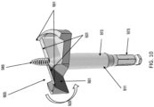
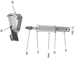
- the system 900 includes a shank 911 and a cutting head 906.
- the cutting head 906 includes two sector-shaped base walls 921 configured to be coupled to the shank 911.
- Each of the two sector-shaped base walls 921 may extend at most approximately 90° (e.g., from about 20° to about 45°) around a circumference of a circle and together do not complete a 360° circumference of the circle.
- Fig. 9 illustrates two sector-shaped base walls, embodiments of the present application are not limited thereto. One or more than two sector-shaped base walls may be provided without departing from the scope of the present application.
- each of the two sector-shaped base walls 921 are bounded by a radial wall 932 extending forward from the base 921 and facing a cutting direction 925 with a radial cutting edge (cutters) 931 disposed on the radial wall.
- the two-sector shaped base walls 921 further include a peripheral wall 941 extending forward from the base 921 and including a cutting spur 951 at a leading corner of a peripheral wall 941 facing in a cutting direction 925.
- the cutting spur 951 extends axially forward of the radial cutting edge 931.
- the shank 911 may further include a rear portion 973 configured to be coupled to the tool holder of t981he power tool (not shown), an intermediate portion 972 extending axially forward from the rear portion and a front portion 971 extending axially forward from the intermediate portion 972.
- the rear portion 973 may have a hexagonal shape, but is not limited thereto.
- the intermediate 972 and front 971 portions may have a cylindrical shape, but again are not limited thereto.
- the shank 911 may be configured to be removably and non-rotatably couplable to the cutting head 906.
- the shank 911 may further include an integral or removable at least partially threaded tip 945 coupled to the front portion 971 and extending axially forward of the spurs 951.
- each of the radial walls 932 include angled rake faces 961, which each have a radial cutting edge 931.
- the radial cutting edge 931 may either be integral with the angled rake face 961 or a separate blade that is removably attached to the angled rake face 961 without departing from the scope of the present application.
- a center of the cutting head 906 includes a circular central opening 981 to receive the shank 911.
- the cutting head 906 and the shank 911 are permanently affixed together.
- the cutting head 906 and the shank 911 may be permanently affixed together by one or more of press fitting, welding, brazing, or adhesive.
- embodiments are not limited to these methods.
- the cutting head and/or the at least partially threaded cutting tip may be removably coupled to the shank in a tool-free manner (e.g., without use of a secondary tool), for example, using the threaded couplings described above with respect to Figs. 1-5 .
- the shank and the cutting head may be manufactured separately by, for example, forging, casting, machining, and the like, and then the cutting head may be removably or permanently affixed to the shank. Permanently affixing the shank to the cutting head may be done by, for example, one or more of press fitting, welding, brazing, adhesive, or the like.
- the modular manufacturing design may allow the shank and the cutting head to be made for a lower cost, using stronger materials.
- self-feed bit systems of the types described above may be included in a package 1200.
- a plurality of self-feed bits 1210a, 1210b, 1210c, 1210d are packaged in an alternating nested pattern to reduce volume of the package 1200. It will be understood that these self-feed bits may have different cutting heads to suit different projects.
- four self-feed bits 1200a-1200d are shown, embodiments are not limited thereto. For example, less than or more than four self-feed bits in a package 1200 may be provided without departing from the scope of the present application.
- a self-feed bit system including a shank with an integral threaded tip may reduce the likelihood that the threaded tip will come loose or fall off.
- the shank includes a rear hex shaped portion, a larger diameter cylindrical intermediate portion, and a smaller diameter cylindrical front portion that is integrally formed with the threaded tip.
- the cutting head has two sector-shaped base walls, each extending at most approximately 90° (e.g., approximately 20-45°) around the circumference of a circle (as opposed to 360° in traditional self-feed bits). Making the base walls sector shaped may reduce the amount of torque needed to cut a hole.
- the base walls are each bounded on their peripheral edge by a peripheral wall extending axially forward from the base and including a cutting spur at a leading corner of the peripheral wall facing in the cutting direction.
- the cutting spurs may allow the formation of cleaner holes and require lower effort to punch through the end of a hole.
- the base walls are also each bounded along their leading radial edge by angled rake faces, each having a radial cutting edge, which may be integral with the rake face or may be on a separate blade that is removably attached to the rake face.
- the self-feed bit systems of the present application are able to achieve significantly reduced torque when forming a hole in a workpiece as compared to existing self-feed bits.
- a prototype self-feed bit of the type shown in Figs. 5A-5B with a diameter of 2-9/16" was compared against an Irwin ® Speedbor Supreme TM 2-9/16" self-feed bit (model no. 2691730), sold by Irwin Industrial Tool Co. and a Milwaukee ® Switchblade TM 2-9/16" self-feed bit (model no. 48-25-5150), sold by Milwaukee Electric Tool Corp., when drilling holes in 2" thick pine using a DEWALT 20V MAX Cordless Brushless 7/16 in.
- the Irwin self-feed bit and the Milwaukee self-feed bit have a threaded tip with a higher thread pitch, peripheral teeth that are higher in height than the cutting blade, and high speed steel teeth instead of carbide or cermet.
- the Irwin self-feed bit, the Milwaukee self-feed bit, and the prototype self-feed bit had an average drilling torque of approximately 11.8 Nm, 10.8 Nm, and 8.6 Nm, respectively.
- the prototype had approximately 27% and 20% improvement over the Irwin and Milwaukee self-feed bits, respectively.
- the same prototype self-feed bit was compared against the same Irwin and Milwaukee bits int eh same test, but instead using a DEWALT 20V MAX Brushless Cordless 1/2-in Hammer Drill Driver(model no. DCD999).
- the Irwin self-feed bit, the Milwaukee self-feed bit, and the prototype self-feed bit had an average drilling torque of approximately 6.5 Nm, 6.9 Nm, and 4.6 Nm, respectively.
- the prototype had approximately 29% and 34% improvement over the Irwin and Milwaukee self-feed bits, respectively.
- Example embodiments have been provided so that this disclosure will be thorough, and to fully convey the scope to those who are skilled in the art. Numerous specific details are set forth such as examples of specific components, devices, and methods, to provide a thorough understanding of embodiments of the present disclosure. It will be apparent to those skilled in the art that specific details need not be employed, that example embodiments may be embodied in many different forms and that neither should be construed to limit the scope of the disclosure. In some example embodiments, well-known processes, well-known device structures, and well-known technologies are not described in detail.
- first, second, third, etc. may be used herein to describe various elements, components, regions, layers and/or sections, these elements, components, regions, layers and/or sections should not be limited by these terms. These terms may be only used to distinguish one element, component, region, layer or section from another region, layer or section. Terms such as “first,” “second,” and other numerical terms when used herein do not imply a sequence or order unless clearly indicated by the context. Thus, a first element, component, region, layer or section discussed below could be termed a second element, component, region, layer or section without departing from the teachings of the example embodiments.
Landscapes
- Engineering & Computer Science (AREA)
- General Engineering & Computer Science (AREA)
- Mechanical Engineering (AREA)
- Life Sciences & Earth Sciences (AREA)
- Wood Science & Technology (AREA)
- Forests & Forestry (AREA)
- Milling Processes (AREA)
Abstract
Description
- This present application relates generally to a self-feed bit system.
- Self-feed bits may be used for cutting holes in materials, such as wood for passing pipe or conduit through the hole, and other applications. These types of bits generally include a shank that has one end adapted to be connected to, for example, a chuck of a rotary tool such as a drill or power driver. The opposite end of the shank supports a cutting head having an annular cutting edge. A screw tip may be provided for feeding a cutting member into and through the wood. A cutting member may be disposed between the cutting edge and the tip. The bit may be rotated at high speed such that the teeth score the edge of the hole, and the cutting member bores the interior of the hole. While various types of self-feed bits are available, improved self-feed bits and related systems that use self-feed bits are desired.
- Some embodiments of the present application provide a self-feed bit system including a shank extending along an axis and configured to be coupled to a tool holder of a power tool and a cutting head couplable to the shank and including a sector shaped base. A radially extending lip is at a leading edge of the sector shape facing in a cutting direction and includes a rake face facing the cutting direction at a rake angle relative to the axis. A radially extending cutting blade is coupled to the radially extending lip and extends axially forward from the base at a first height. An at least partially threaded tip is coupled to the shank and extends axially forward of the cutting blade. Two or more teeth are positioned on a perimeter of the base trailing the cutting blade. Each tooth extends axially forward from the base at a second height measured in an axial direction relative to a bottom of the base, the second height being less than the first height.
- Implementations of these embodiments may include one or more of the following. The first height may be approximately one-half inch greater than the second height. The sector shaped base may extend around at least 180° and at most 300° of a circumference of a circle. The cutting blade may be removably coupled to the lip to facilitate replacement of the cutting blade. The at least partially threaded tip may be removably coupled to the shank. The at least partially threaded tip may include a thread having a pitch of less than or equal to 1.2 mm. The rake angle may be at least 40°. The teeth may comprise carbide or cermet. The cutting blade may comprise carbide or cermet. The cutting head may be integral with the shank. The cutting head may be removably coupled to the shank in a tool-free manner. The cutting head may comprise two or more removeable and interchangeable cutting heads having different diameters or features that are interchangeably coupleable to a front end of the shank. The cutting head may include a first threaded portion and the shank includes a second threaded portion that may be threadably attached to the first threaded portion to removably couple the cutting head to the shank. The first threaded portion may include a threaded stub extending axially rearward of the cutting head and the second threaded portion may include a threaded collar configured to be threaded to the threaded stub and coupled to the shank.
- Other embodiments of the present application provide a self-feed bit system including a shank extending along an axis and configured to be coupled to a tool holder of a power tool, and a cutting head couplable to the shank and including a sector shaped base, a radially extending lip at a leading edge of the sector shape facing in a cutting direction, the lip including a rake face facing the cutting direction at a rake angle relative to the axis. A radially extending cutting blade is coupled to the radially extending lip and extends axially forward from the base at a first height measured in an axial direction relative to a bottom of the base. An at least partially threaded tip coupled to the shank and extending axially forward of the cutting blade. The cutting head is removably couplable to the shank in a tool-free manner.
- Implementations of these embodiments may include one or more of the following. The cutting head may include a first threaded portion and the shank may include a second threaded portion that may be threadably attached to the first threaded portion to removably couple the cutting head to the shank. The first threaded portion may include a threaded stub extending axially rearward of the cutting head and the second threaded portion may include a threaded collar configured to be threaded to the threaded stub and coupled to the shank. The cutting head may include a plurality of removable and interchangeable cutting heads, and the system may further include a package inside of which the shank and the plurality of the one or more removable and interchangeable cutting heads are packaged with the plurality of cutting heads lying flat within the package.
- Other embodiments of the present application provide a self-feed bit system including a shank extending along an axis and configured to be coupled to a tool holder of a power tool, and a cutting head couplable to the shank and including a sector shaped base, and a radially extending lip at a leading edge of the sector shape facing in a cutting direction. The lip includes a rake face facing the cutting direction at a rake angle relative to the axis, wherein the rake angle is at least 40°. A radially extending cutting blade is coupled to the radially extending lip and extends axially forward from the base at a first height measured in an axial direction relative to a bottom of the base. An at least partially threaded tip is coupled to the shank and extends axially forward of the cutting blade wherein the at least partially threaded tip includes a thread having a pitch of less than or equal to 1.2 mm. Two or more teeth are positioned on a perimeter of the base trailing the cutting blade, each tooth extending axially forward from the base at a second height measured in an axial direction relative to a bottom of the base, wherein the teeth comprise carbide or cermet.
- Implementations of these embodiments may include one or more of the following. The cutting head may be integral with the shank. The cutting head may be removably coupled to the shank in a tool-free manner. The cutting head may comprise two or more removeable and interchangeable cutting heads having different diameters or features that are interchangeably coupleable to a front end of the shank. The cutting head may include a first threaded portion and the shank includes a second threaded portion that may be threadably attached to the first threaded portion to removably couple the cutting head to the shank. The first threaded portion may include a threaded stub extending axially rearward of the cutting head and the second threaded portion may include a threaded collar configured to be threaded to the threaded stub and coupled to the shank.
- Some embodiments of the present application provide self-feed bit systems including a shank extending along an axis and configured to be coupled to a tool holder of a power tool and a cutting head couplable to the shank. The cutting head includes a sector shaped base that extends around at least a majority and less than an entirety (e.g., at least 180 degrees and at most 300 degrees) of a circumference of a circle. The base is generally flat with an upwardly projecting and radially extending lip at a leading edge of the sector facing in a cutting direction. The lip includes an angled rake face facing a cutting direction and a radially extending locking groove that receives a removable and replaceable cutting blade. The cutting head includes two or more perimeter teeth positioned on the base that trail the removable and replaceable cutting blade and are at a lower height than the cutting blade.
- In further embodiments, the cutting head may be removably couplable to the shank. In certain embodiments, the cutting head may be a first cutting head and the system may further include a second cutting head that is removably couplable to the shank and interchangeable with the first cutting head.
- In still further embodiments, the cutting head may be integral with the shank.
- In some embodiments, the two or more perimeter teeth may be at a lower height than the cutting blade to reduce friction and protect the two or more perimeter teeth from nail strikes. In certain embodiments, the cutting blade may be about one half inch higher than the two or more perimeter teeth in a vertical direction from a surface of the base.
- In further embodiments, the sector shaped base may extend around at least 150 degrees and at most 300 degrees of the circumference of the circle.
- In still further embodiments, the cutting blade may be held in the locking groove by a set screw.
- In some embodiments, the shank may include a rear portion configured to be coupled to the tool holder of the power tool, an intermediate portion extending axially forward from the rear portion, a front portion extending axially forward from the intermediate portion and configured to be removably and non-rotatably couplable to the cutting head, and an at least partially threaded tip coupled to the front portion and extending axially forward of the cutting blade.
- In further embodiments, the rear portion may have a polygonal cross-section.
- In still further embodiments, the intermediate portion may be generally cylindrical.
- In some embodiments, the threaded tip may be removably coupled to the front portion. In certain embodiments, the front portion may have a non-circular cross section and the cutting head may have a central opening with a non-circular cross section that is configured to non-rotatably receive the front portion. In further embodiments, the non-circular cross section of the front portion may have a double-D shape and the non-circular cross section of the central opening may have a double-D shape.
- In further embodiments, the cutting head may further include an externally threaded stub extending axially rearward from a center of an underside of the base.
- In still further embodiments, the cutting head may include one or more removeable and interchangeable cutting heads that include a plurality of different cutting heads having different diameters or features that are interchangeably attachable to a front end of the shank.
- In some embodiments, the shank may include a generally cylindrical collar that is threadably couplable to the threaded stub for removably coupling the cutting head to the shank. The collar may be axially retained on the shank by a ring received in an external annular groove in the intermediate portion of the shank and in an internal annular groove in the collar.
- In further embodiments, the collar may be a hollow cylinder and may include internal threads inside a front end. The internal threads may be configured to mate with external threads on the threaded stub of the cutting head.
- In still further embodiments, the collar may have a knurled outer surface to facilitate gripping by a user.
- In some embodiments, the cutting head may include a plurality of removable and interchangeable cutting heads. The system may further include a compact package inside of which the shank and the plurality of the one or more removable and interchangeable cutting heads are packaged with the plurality of cutting heads lying flat within the package.
- In further embodiments, a single cutting head is fixed to a single shank.
- In still further embodiments, the cutting head may be removeable and interchangeable and may not be fixed to the shank.
- In some embodiments, the removable and interchangeable cutting head may be attached to the shank without use of a collar.
- Further embodiments of the present application provide self-feed bit systems including a shank extending along an axis and a cutting head. The cutting head has at least two sector-shaped base walls configured to be couplable to the shank, each extending at most approximately 90° (e.g., from about 20 degrees to about 45 degrees) around a circumference of a circle and together do not complete a 360 circumference of the circle. Each of the at least two sector-shaped base walls are bounded by a radial wall extending forward from the base and facing a cutting direction with a radial cutting edge disposed on the radial wall, and a peripheral wall extending forward from the base and including a cutting spur at a leading corner of a peripheral wall facing in a cutting direction, the cutting spur extending axially forward of the radial cutting edge.
- In still further embodiments, the shank may further include a rear portion configured to be coupled to the tool holder of the power tool, an intermediate portion extending axially forward from the rear portion, a front portion extending axially forward from the intermediate portion and configured to be removably and non-rotatably couplable to the cutting head, and an at least partially threaded tip coupled to the front portion and extending axially forward of the spurs.
- In some embodiments, each of the radial walls may include angled rake faces. Each of the angled rake faces may have a radial cutting edge. Each radial cutting edge may be one of integral with an angled rake face or a separate blade that is removably attached to the angled rake face.
- In further embodiments, a center of the cutting head may include a circular central opening to receive the shank.
- In still further embodiments, the cutting head and the shank may be permanently affixed together. The cutting head and the shank may be permanently affixed together by one of press fitting, welding, and brazing.
- In some embodiments, the system may further include a package including a set of the self-feed bits that are packaged in an alternating nested pattern in the package to reduce volume of the package. Self-feed bit systems may include a shank extending along an axis and configured to be coupled to a tool holder of a power tool and a cutting head couplable to the shank. The cutting head includes a sector shaped base that extends around at least a majority and less than an entirety (e.g., at least 180 degrees and at most 300 degrees) of a circumference of a circle. The base is generally flat with an upwardly projecting and radially extending lip at a leading edge of the sector facing in a cutting direction. The lip includes an angled rake face facing a cutting direction and a radially extending locking groove that receives a removable and replaceable cutting blade. The cutting head further includes an externally threaded stub extending axially rearward from a center of an underside of the base and the shank includes a generally cylindrical collar that is threadably couplable to the threaded stub for removably coupling the cutting head to the shank.
- Still further embodiments of the present application provide a cutting head couplable to a shank extending along an axis and configured to be coupled to a tool holder of a power tool. The cutting head includes a sector shaped base that extends around at least a majority and less than an entirety (e.g., at least 180 degrees and at most 300 degrees of a circumference of a circle. The base is generally flat with an upwardly projecting and radially extending lip at a leading edge of the sector facing in a cutting direction. The lip includes an angled rake face facing a cutting direction and a radially extending locking groove that receives a removable and replaceable cutting blade. The cutting head includes two or more perimeter teeth positioned on the base that trail the removable and replaceable cutting blade and are at a lower height than the cutting blade.
- Advantages may include one or more of the following. The self-feed bits discussed herein may have cutting heads that are more durable, have longer life, are more efficient, have reduced torque, and/or have greater cutting speed. Furthermore, the cutting heads may be removable and interchangeable with a more efficient attaching system. These and other advantages and features will be apparent from the description and the drawings.
-
-
Fig. 1 is a perspective view of a self-feed bit system in accordance with some embodiments of the present application. -
Fig. 2A is a perspective view of the cutting head of the self-feed bit system ofFig. 1 having a cutting blade removed therefrom in accordance with some embodiments of the present application. -
Fig. 2B is a perspective view of the cutting head of the self-feed bit system ofFig. 1 having the cutting blade positioned thereon in accordance with some embodiments of the present application. -
Fig. 3A is top perspective view of the self-feed bit system ofFig. 1 illustrating positioning of the cutting head on a shank in accordance with some embodiments of the present application. -
Fig. 3B is a cross section of a portion of the self-feed bit system ofFig. 1 , illustrating coupling between the cutting head and the shank in accordance with some embodiments of the present application. -
Figs. 4A and4B are perspective views of the self-feed bit system illustrating positioning of a cutting head on a shank in accordance with some embodiments of the present application. -
Figs. 5A and 5B are perspective views of another embodiment of a self-feed bit system having a fixed shank, fixed feed screw, and removable blade in accordance with some embodiments of the present application. -
Figs. 6A and 6B are perspective views of another embodiment of a self-feed bit system having a removable shank and removable blade in accordance with some embodiments of the present application. -
Figs. 7A and 7B are perspective views of another embodiment of a self-feed bit system having a removable shank, removable main blade and removable feed screw with no tightening collar in accordance with some embodiments of the present application. -
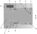
Fig. 8 is a perspective view illustrating packaging including a shank and multiple cutting heads in a package in accordance with some embodiments of the present application. -
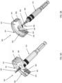
Fig. 9 a perspective view of a self-feed bit system in accordance with other embodiments of the present application. -
Fig. 10 is a perspective view illustrating the self-feed bit system ofFig. 9 positioned on a shank in accordance with some embodiments of the present application. -
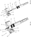
Fig. 11 is a perspective view of the self-feed bit system ofFig. 9 showing the cutting head being positioned on the shank in accordance with some embodiments of the present application. -
Fig. 12 is a diagram of a self-feed bit system with cutting heads and shanks arranged in an alternating nesting configuration to reduce a volume of the package in accordance with some embodiments discussed herein. -
FIGS. 13 and14 are graphs illustrating an amount of torque required to form holes using the self-feed bit systems in accordance with the present application. - As discussed above, self-feed bits may be used for cutting holes in materials, such as forming holes in wood to receive pipe, conduit, and for other applications. These types of bits generally include a shank that has one end adapted to be connected to, for example, a chuck of a rotary tool such as a drill or power driver. While various types of self-feed bits are known, improved self-feed bits and related systems that used self-feed bits are desired.
- Accordingly, embodiments of the present application provide self-feed bits and related cutting heads and systems that may be more durable, have longer life, may be more efficient, may have lower torque, and/or may have greater cutting speed than conventional bits and systems. For example, in some embodiments of the present application, a cutting head is provided that is designed to provide protection to perimeter teeth from nail strikes and, therefore, may prolong the life of the cutting head itself. Further embodiments provide a system that includes a threaded collar that facilitates attaching the cutting head to the shank. These example embodiments and details of further embodiments will be discussed herein with respect to
Figs. 1 through 12 . - Referring first to
Fig. 1 , a perspective view of a self-feed bit system 100 in accordance with some embodiments of the present application will be discussed. As illustrated, the self-feed bit system 100 includes a cuttinghead 105 that is positioned on ashank 110. Theshank 110 is configured to be coupled to a tool holder of a power tool (not shown) allowing the cuttinghead 105 to create a hole in a workpiece. As will be discussed further herein, theshank 110 may be fixed to or integral with the cuttinghead 105 in some embodiments. However, in some embodiments, the cuttinghead 105 may be removeable and interchangeable in a tool-free manner (e.g., without the use of a secondary tool). In particular, different cutting heads 105 may be positioned on asame shank 110 and used to create holes of various sizes without departing from the scope of the present application. Various methods may be used to couple the various cutting heads 105 to the shank as will be discussed further herein. - Referring again to
Fig. 1 , the cuttinghead 105 includes a sector shapedbase 115 that extends around at least a majority and less than an entirety (e.g., at least 180 degrees and at most 300 degrees) of a circumference of a circle. In some embodiments, the circumference of the circle may be from about 150° to about 300°. However, embodiments are not limited thereto. As illustrated, thebase 115 may be generally flat with an upwardly projecting and radially extendinglip 120 at a leading edge of the sector facing in acutting direction 125. Thelip 120 includes anangled rake face 151 facing a cuttingdirection 125 and a radially extending locking groove (150,Fig. 2A ) that receives a removable andreplaceable cutting blade 155. Therake face 151 is at a rake angle θ to a longitudinal axis X of theshank 110. The rake angle θ is greater than the rake angle in know self-feed bits (e.g., at least 40° as compared to approximately 35° in known self-feed bits), which helps reduce the amount of torque needed to drive the self-feed bit through a workpiece. Thecutting blade 155 is disposed at a first height H1 relative to the bottom of thebase 115. In addition, thecutting blade 155 may be made of a hard metal, such as carbide or cermet, to increase the life of theblade 135 and the self-feed drill bit. It will be understood that thecutting blade 155 is generally replaceable, but embodiments of the present application are not limited thereto. Thecutting blade 155 may be fixed without departing from the scope of the present application. - As further illustrated in
Fig. 1 , the cuttinghead 105 further includes two ormore perimeter teeth 130 positioned on the base 115 that trail the removable andreplaceable cutting blade 155. The two ormore perimeter teeth 130 are disposed on the perimeter of the base 114 are at a second height H2 relative to the bottom of thebase 115. The second height H2 of theperimeter teeth 130 is lower than the first height H1 of thecutting blade 155. Theperimeter teeth 130 may be made of a hard metal, such as carbide or cermet, to increase the life of theteeth 130 and the self-feed drill bit. - Referring now to
Figs. 2A and2B , perspective views of the cutting head in accordance with some embodiments of the present application will be discussed. As illustrated inFigs. 2A , the two ormore perimeter teeth 130 may be at a lower height than thecutting blade 155 in some embodiments to reduce friction and protect the two ormore perimeter teeth 130 from nail strikes. This lower height H2 also allows thecutting blade 155 to make the initial cut and removal of the material, while theperimeter teeth 130 clear chips and result in a smoother finished edge of the hole formed in the workpiece. For example, the height H1 of thecutting blade 155 may be about one half inch higher than the height H2 of the two ormore perimeter teeth 130. - As illustrated in
Figs. 2A and2B , thecutting blade 155 may be held in the lockinggroove 150 by aset screw 160. The provision of theset screw 160 allows thecutting blade 155 to be easily replaced by loosening and tightening the set screw. It should be understood that more than one set screw may be employed without departing from the scope of the present application. - Referring again to
Fig. 1 , theshank 110 may include arear portion 135, anintermediate portion 140 extending axially forward from therear portion 135, a front portion (365,Fig. 3A ) extending axially forward from theintermediate portion 140, and an at least partially threadedtip 145 coupled to thefront portion 365. The at least partially threadedtip 145 has a thread pitch that is less than that used on threaded tips in known self-feed bits. The thread pitch is the distance between threads measured along the axis X. For example, the thread pitch of thetip 145 may be 1.2 mm or less, while known self-feed bits may have a thread pitch of 1.6 mm or greater. This lower thread pitch reduces the amount of toque needed for the self-feed bits to drill into a workpiece. - The
rear portion 135 is configured to be coupled to the tool holder of the power tool (not shown). The front portion (365,Fig. 3A ) may be configured to be removably and non-rotatably couplable to the cuttinghead 105. The at least partially threadedtip 145 may extend axially forward of thecutting blade 155. The threadedtip 145 may be fixed to or removably coupled to the front portion in various embodiments. - Referring now to
Figs. 1 through and 3B, therear portion 135 may have a polygonal cross-section. The cross section illustrated inFig. 1 is a "hex" shape, however, embodiments of the present application are not limited thereto. Theintermediate portion 140 may be generally cylindrical. - The
front portion 365 has a non-circular cross section and the cuttinghead 105 has acentral opening 370 with a non-circular cross section that is configured to receive the front portion. As illustrated inFig. 3A , in some embodiments the non-circular cross section of thefront portion 365 has a "double-D" shape and the non-circular cross section of thecentral opening 370 has a "double-D shape." The "double D" shapes portions appearing like two "Ds" back to back. It will be understood that embodiments are not limited to this configuration. In some embodiments, as shown, the front portion may have two portions including a small generallycylindrical portion 366 and anon-circular front portion 365. The small generallycylindrical portion 366 is smaller than the generally cylindricalintermediate portion 140. Furthermore, aconical surface 367 is provided between the small diameter cylindrical front portion and the double-D shaped front portion. - As further illustrated in
Fig. 3A , the cuttinghead 105 and theshank 110 may be removably coupled to each other in a tool-free manner by a tool-free attachment mechanism 101. In one embodiment of a tool-free attachment mechanism 101, the cuttinghead 105 may further include an externally threadedstub 375 extending axially rearward from a center of an underside of thebase 115. In some embodiments, theshank 110 may include a generallycylindrical collar 185 that is threadably couplable to the threadedstub 375 for removably coupling the removable and interchangeable cutting heads 105 to theshank 110. It will be understood that all parts of the shank and cutting head can be fixed (i.e., non-removeable and interchangeable) without departing from the scope of the present application. - As further illustrated in
Figs. 3A and3B , thecollar 185 may be axially retained on theshank 110 by a ring 395 (snap ring) received in an externalannular groove 396 in theintermediate portion 140 of theshank 110 and in an internalannular groove 397 in thecollar 185. In some embodiments, thecollar 185 may be a hollow cylinder that includesinternal threads 380 inside a front end. Theinternal threads 380 are configured to mate with external threads on the threadedstub 375 of the cuttinghead 105. Thecollar 185 may be made to have a surface that facilitates gripping of thecollar 185. For example, in some embodiments thecollar 185 has a knurledouter surface 390 to facilitate gripping by a user. - Referring now to
Figs. 4A and4B , diagrams of the system illustrating loosening and tightening thecollar 185 in accordance with some embodiments of the present application will be discussed. As illustrated inFig. 4A , to loosen thecollar 185, the collar is rotated in aaloosening direction 127 opposite from the cuttingdirection 125. Similarly, to tighten thecollar 185, the collar is rotated in a tighteningdirection 129 that is the same as the cuttingdirection 125.Fig. 4B further illustrates alarger cutting head 105 being replace with a smaller cutting head 105'. It will be understood that the loosening and tightening directions may be swapped without departing from the scope of the present application. - In practice, to install a cutting
head 105 on theshank 110, the opening on the cutting head is aligned with the front end of the shank and the front end of the shank is inserted through the central opening in the cutting head. The collar is then rotated in the tightening direction 129 (which in this case is the same direction as the cutting direction 125) and the threads on the collar engage the threads on the stub and pull the cutting head rearward onto the shank. To remove and interchange the cutting heads, the collar is rotated in theopposite loosening direction 127 and the cutting head is removed axially from the shank. - It will be understood that although some embodiments discussed herein include a collar to facilitate attachment of the shank to the cutting head, embodiments of the present application is not limited thereto. In particular, in embodiments having a removable and interchangeable cutting head, the shank may be attached to the cutting head without use of a collar (e.g.,
Fig. 7B ). - As discussed above, the shank, cutting head, the threaded tip, and the cutting blade may be integrated into fewer pieces or may be separated into additional separate pieces. Various systems with different levels of integration will now be discussed.
-
Figs. 5A and 5B illustrate another embodiment of a self-feed bit system 500 having ashank 510, a cuttinghead 505, a threadedtip 545, and acutting blade 555. Theshank 510 and threadedtip 545 are integrally attached to each other and to the cuttinghead 505. Theshank 510 and the threadedtip 545 are otherwise similar to theshank 110 and threadedtip 145 of self-feed bit system ofFig. 1 . The cuttinghead 505 differs from the cuttinghead 105 in the following aspects. The cuttinghead 505 includes a sector shaped base 515 (e.g., extending a majority (e.g., approximately 150° to about 300° about a circumference of a circle, and a plurality ofperipheral walls 541 extending axially forward of the base wall 515 to define acavity 521 in the cuttinghead 505. Eachperipheral wall 541 is slanted or tapered downward in a direction opposite the cuttingdirection 525. - A
radial lip 520 extends radially outward from theshank 510 to theperipheral wall 541. Thecutting blade 555 is received in arecess 543 in thelip 520 and attached by aset screw 560, which provide ease of replacement. Thelip 520 includes anangled rake face 551 facing the cuttingdirection 525. Therake face 551 is at a rake angle θ to a longitudinal axis X of theshank 510. The rake angle θ is greater than the rake angle in know self-feed bits (e.g., at least 40° as compared to approximately 35° in known self-feed bits), which helps reduce the amount of torque needed to drive the self-feed bit through a workpiece. Thecutting blade 555 is disposed at a first height H1 relative to the bottom of the base 515. In addition, thecutting blade 555 may be made of a hard metal, such as carbide or cermet, to increase the life of the blade 535 and the self-feed drill bit. - Each
peripheral wall 541 is formed with aperimeter tooth 547 that trails thecutting blade 555 in the cuttingdirection 525. Theperimeter teeth 547 are disposed on the perimeter of the base 515 are at a second height H2 relative to the bottom of the base 515. The second height H2 of theperimeter teeth 547 is lower than the first height H1 of thecutting blade 555. Theperimeter teeth 547 may be made of a hard metal, such as carbide or cermet, to increase the life of theteeth 547 and the self-feed drill bit. -
Figs. 6A and 6B illustrate another embodiment of a self-feed bit system 600 having ashank 610, a cuttinghead 605, a threadedtip 645, and acutting blade 655 that are substantially similar to theshank 510, cuttinghead 505, threadedtip 545, and cuttingblade 555 ofFigs. 5A and 5B , except with the following differences. Theshank 610 and threadedtip 645 are integrally attached to each other similar to the integrally attachedshank 110 and threadedtip 145 described above with respect toFig. 1 . Theshank 610 includes a threadedcollar 685 similar to the threadedcollar 185 on theshank 110 and the cuttinghead 605 has a threadedstub 676 similar to threadedstub 376 on cuttinghead 105, to removably couple the cuttinghead 605 to theshank 610 in the same manner as described above with respect to the embodiment ofFIG. 1 . -
Figs. 7A and 7B illustrate another embodiment of a self-feed bit system 700 having ashank 710, a cuttinghead 705, a threadedtip 745, and acutting blade 755 that that are substantially similar to theshank 610, cuttinghead 605, threadedtip 645, and cuttingblade 655 ofFigs. 6A and 6B , except with the following differences. In this embodiment, the threadedtip 745 is removable coupled to theshank 710. The threadedtip 745 includes arearward projection 747 that is removably received in afront opening 711 of theshank 710, e.g., by a friction or interference fit of an O-ring 749 on therearward projection 747. - As illustrated in
Fig. 8 , in an embodiment, various elements of the system in accordance with embodiments discussed herein may be packaged together for convenience. In the embodiment ofFig. 8 , apackage 800 includes four cuttingheads shank 810 similar to the cutting heads 105, 505, 605, 705 andshanks packaging 800, for example, cutting blades, more than one shank, etc. Thus, various elements of the system may be included in a compact package. - As discussed above, embodiments of the present application, by provision of perimeter teeth of a lower height than the height of the cutting blade, may have greater durability, longer life, greater efficiency, and/or faster cutting speed. Furthermore, embodiments that provide a modular system that is easily assembled and disassembled using a threaded collar for removably attaching the head to the shank may facilitate greater usefulness and move compact packaging at a lower cost and with fewer parts.
- Referring now to
Figs. 9 through 12 , a self-feed bit system in accordance with further embodiments of the present application will be discussed. As illustrated inFig. 9 , the system 900 includes ashank 911 and a cuttinghead 906. The cuttinghead 906 includes two sector-shapedbase walls 921 configured to be coupled to theshank 911. Each of the two sector-shapedbase walls 921 may extend at most approximately 90° (e.g., from about 20° to about 45°) around a circumference of a circle and together do not complete a 360° circumference of the circle. It will be understood that althoughFig. 9 illustrates two sector-shaped base walls, embodiments of the present application are not limited thereto. One or more than two sector-shaped base walls may be provided without departing from the scope of the present application. - As further illustrated in
Fig. 9 , each of the two sector-shapedbase walls 921 are bounded by aradial wall 932 extending forward from thebase 921 and facing a cuttingdirection 925 with a radial cutting edge (cutters) 931 disposed on the radial wall. The two-sector shapedbase walls 921 further include aperipheral wall 941 extending forward from thebase 921 and including acutting spur 951 at a leading corner of aperipheral wall 941 facing in acutting direction 925. The cutting spur 951 extends axially forward of theradial cutting edge 931. - As further illustrated in
Figs. 10 and11 , theshank 911 may further include arear portion 973 configured to be coupled to the tool holder of t981he power tool (not shown), anintermediate portion 972 extending axially forward from the rear portion and afront portion 971 extending axially forward from theintermediate portion 972. As illustrated, therear portion 973 may have a hexagonal shape, but is not limited thereto. Similarly, the intermediate 972 and front 971 portions may have a cylindrical shape, but again are not limited thereto. In some embodiments, theshank 911 may be configured to be removably and non-rotatably couplable to the cuttinghead 906. As further illustrated, theshank 911 may further include an integral or removable at least partially threadedtip 945 coupled to thefront portion 971 and extending axially forward of thespurs 951. - As further illustrated in
Fig. 10 , each of theradial walls 932 include angled rake faces 961, which each have aradial cutting edge 931. Theradial cutting edge 931 may either be integral with theangled rake face 961 or a separate blade that is removably attached to theangled rake face 961 without departing from the scope of the present application. - As illustrated in the exploded view of
Fig. 11 , a center of the cuttinghead 906 includes a circularcentral opening 981 to receive theshank 911. In some embodiments, the cuttinghead 906 and theshank 911 are permanently affixed together. For example, the cuttinghead 906 and theshank 911 may be permanently affixed together by one or more of press fitting, welding, brazing, or adhesive. However, embodiments are not limited to these methods. For example, the cutting head and/or the at least partially threaded cutting tip may be removably coupled to the shank in a tool-free manner (e.g., without use of a secondary tool), for example, using the threaded couplings described above with respect toFigs. 1-5 . - As discussed above, embodiments of the present application provide both fixed and modular embodiments. Thus, all element of the systems discussed above with respect to
Figs. 1 through 11 may be fixed in place or made to be removeable and/or replaceable without departing from the scope of the present application. Removeable and replaceable elements of the system are desirable as it reduces cost by not being required to replace the entire system. - During manufacturing, in some embodiments, the shank and the cutting head may be manufactured separately by, for example, forging, casting, machining, and the like, and then the cutting head may be removably or permanently affixed to the shank. Permanently affixing the shank to the cutting head may be done by, for example, one or more of press fitting, welding, brazing, adhesive, or the like. The modular manufacturing design may allow the shank and the cutting head to be made for a lower cost, using stronger materials.
- As illustrated in
Fig. 12 , in another embodiment self-feed bit systems of the types described above may be included in apackage 1200. In embodiments illustrated inFig. 12 , a plurality of self-feed bits 1210a, 1210b, 1210c, 1210d are packaged in an alternating nested pattern to reduce volume of thepackage 1200. It will be understood that these self-feed bits may have different cutting heads to suit different projects. Furthermore, although four self-feed bits 1200a-1200d are shown, embodiments are not limited thereto. For example, less than or more than four self-feed bits in apackage 1200 may be provided without departing from the scope of the present application. A self-feed bit system including a shank with an integral threaded tip may reduce the likelihood that the threaded tip will come loose or fall off. In some embodiments, the shank includes a rear hex shaped portion, a larger diameter cylindrical intermediate portion, and a smaller diameter cylindrical front portion that is integrally formed with the threaded tip. In the illustrated embodiments, the cutting head has two sector-shaped base walls, each extending at most approximately 90° (e.g., approximately 20-45°) around the circumference of a circle (as opposed to 360° in traditional self-feed bits). Making the base walls sector shaped may reduce the amount of torque needed to cut a hole. The base walls are each bounded on their peripheral edge by a peripheral wall extending axially forward from the base and including a cutting spur at a leading corner of the peripheral wall facing in the cutting direction. The cutting spurs may allow the formation of cleaner holes and require lower effort to punch through the end of a hole. The base walls are also each bounded along their leading radial edge by angled rake faces, each having a radial cutting edge, which may be integral with the rake face or may be on a separate blade that is removably attached to the rake face. - The self-feed bit systems of the present application are able to achieve significantly reduced torque when forming a hole in a workpiece as compared to existing self-feed bits. For example, as shown in
Fig. 13 , a prototype self-feed bit of the type shown inFigs. 5A-5B with a diameter of 2-9/16" was compared against an Irwin® Speedbor Supreme™ 2-9/16" self-feed bit (model no. 2691730), sold by Irwin Industrial Tool Co. and a Milwaukee® Switchblade™ 2-9/16" self-feed bit (model no. 48-25-5150), sold by Milwaukee Electric Tool Corp., when drilling holes in 2" thick pine using a DEWALT 20VMAX Cordless Brushless 7/16 in. Quick Change Stud and Joist Drill (model no. DCD445), sold by DEWALT Industrial Tool Co. Unlike the prototype bit, the Irwin self-feed bit and the Milwaukee self-feed bit have a threaded tip with a higher thread pitch, peripheral teeth that are higher in height than the cutting blade, and high speed steel teeth instead of carbide or cermet. The Irwin self-feed bit, the Milwaukee self-feed bit, and the prototype self-feed bit had an average drilling torque of approximately 11.8 Nm, 10.8 Nm, and 8.6 Nm, respectively. Thus, the prototype had approximately 27% and 20% improvement over the Irwin and Milwaukee self-feed bits, respectively. - As shown in
FIG. 13 , the same prototype self-feed bit was compared against the same Irwin and Milwaukee bits int eh same test, but instead using a DEWALT 20VMAX Brushless Cordless 1/2-in Hammer Drill Driver(model no. DCD999). The Irwin self-feed bit, the Milwaukee self-feed bit, and the prototype self-feed bit had an average drilling torque of approximately 6.5 Nm, 6.9 Nm, and 4.6 Nm, respectively. Thus, the prototype had approximately 29% and 34% improvement over the Irwin and Milwaukee self-feed bits, respectively. - Example embodiments have been provided so that this disclosure will be thorough, and to fully convey the scope to those who are skilled in the art. Numerous specific details are set forth such as examples of specific components, devices, and methods, to provide a thorough understanding of embodiments of the present disclosure. It will be apparent to those skilled in the art that specific details need not be employed, that example embodiments may be embodied in many different forms and that neither should be construed to limit the scope of the disclosure. In some example embodiments, well-known processes, well-known device structures, and well-known technologies are not described in detail.
- The terminology used herein is for the purpose of describing particular example embodiments only and is not intended to be limiting. As used herein, the singular forms "a," "an," and "the" may be intended to include the plural forms as well, unless the context clearly indicates otherwise. The terms "comprises," "comprising," "including," and "having," are inclusive and therefore specify the presence of stated features, integers, steps, operations, elements, and/or components, but do not preclude the presence or addition of one or more other features, integers, steps, operations, elements, components, and/or groups thereof. The method steps, processes, and operations described herein are not to be construed as necessarily requiring their performance in the particular order discussed or illustrated, unless specifically identified as an order of performance. It is also to be understood that additional or alternative steps may be employed.
- When an element or layer is referred to as being "on," "engaged to," "connected to," or "coupled to" another element or layer, it may be directly on, engaged, connected or coupled to the other element or layer, or intervening elements or layers may be present. In contrast, when an element is referred to as being "directly on," "directly engaged to," "directly connected to," or "directly coupled to" another element or layer, there may be no intervening elements or layers present. Other words used to describe the relationship between elements should be interpreted in a like fashion (e.g., "between" versus "directly between," "adjacent" versus "directly adjacent," etc.). As used herein, the term "and/or" includes any and all combinations of one or more of the associated listed items.
- Although the terms first, second, third, etc. may be used herein to describe various elements, components, regions, layers and/or sections, these elements, components, regions, layers and/or sections should not be limited by these terms. These terms may be only used to distinguish one element, component, region, layer or section from another region, layer or section. Terms such as "first," "second," and other numerical terms when used herein do not imply a sequence or order unless clearly indicated by the context. Thus, a first element, component, region, layer or section discussed below could be termed a second element, component, region, layer or section without departing from the teachings of the example embodiments.
- Terms of degree such as "generally," "substantially," "approximately," and "about" may be used herein when describing the relative positions, sizes, dimensions, or values of various elements, components, regions, layers and/or sections. These terms mean that such relative positions, sizes, dimensions, or values are within the defined range or comparison (e.g., equal or close to equal) with sufficient precision as would be understood by one of ordinary skill in the art in the context of the various elements, components, regions, layers and/or sections being described.
- In the specification, there have been disclosed embodiments of the application and, although specific terms are used, they are used in a generic and descriptive sense only and not for purposes of limitation.
Claims (14)
- A self-feed bit system, comprising:a shank extending along an axis and configured to be coupled to a tool holder of a power tool;a cutting head couplable to the shank and including a sector shaped base, a radially extending lip at a leading edge of the sector shape facing in a cutting direction, the lip including a rake face facing the cutting direction at a rake angle relative to the axis;a radially extending cutting blade coupled to the radially extending lip and extending axially forward from the base at a first height measured in an axial direction relative to a bottom of the base; andan at least partially threaded tip coupled to the shank and extending axially forward of the cutting blade;two or more teeth positioned on a perimeter of the base trailing the cutting blade, each tooth extending axially forward from the base at a second height measured in an axial direction relative to a bottom of the base, the second height being less than the first height.
- The self-feed bit system of claim 1, wherein the first height is approximately one-half inch greater than the second height.
- The self-feed bit system of claim 1 or claim 2, wherein the sector shaped base extends around at least 180° and at most 300° of a circumference of a circle.
- The self-feed bit system of any one of the preceding claims, wherein the cutting blade is removably coupled to the lip to facilitate replacement of the cutting blade.
- The self-feed bit system of any one of the preceding claims, wherein the at least partially threaded tip is removably coupled to the shank.
- The self-feed bit system of any one of the preceding claims, wherein the at least partially threaded tip includes a thread having a pitch of less than or equal to 1.2 mm.
- The self-feed bit system of any one of the preceding claims, wherein the rake angle is at least 40°.
- The self-feed bit system of any one of the preceding claims, wherein the teeth comprises carbide or cermet.
- The self-feed bit system of any one of the preceding claims, wherein the cutting blade comprises carbide or cermet.
- The self-feed bit system of any one of the preceding claims, wherein the cutting head is integral with the shank.
- The self-feed bit system of any one of claims 1 to 9, wherein the cutting head is removably coupled to the shank in a tool-free manner.
- The self-feed bit system of claim 11, wherein the cutting head comprises two or more removeable and interchangeable cutting heads having different diameters or features that are interchangeably coupleable to a front end of the shank.
- The self-feed bit system of claim 11 or claim 12, wherein the cutting head includes a first threaded portion and the shank includes a second threaded portion that may be threadably attached to the first threaded portion to removably couple the cutting head to the shank.
- The self-feed bit system of claim 13, wherein the first threaded portion comprises a threaded stub extending axially rearward of the cutting head and the second threaded portion includes a threaded collar configured to be threaded to the threaded stub and coupled to the shank.
Applications Claiming Priority (2)
| Application Number | Priority Date | Filing Date | Title |
|---|---|---|---|
| US202263379456P | 2022-10-14 | 2022-10-14 | |
| US18/485,533 US20240125346A1 (en) | 2022-10-14 | 2023-10-12 | Self-feed bit system |
Publications (1)
| Publication Number | Publication Date |
|---|---|
| EP4357091A1 true EP4357091A1 (en) | 2024-04-24 |
Family
ID=88413930
Family Applications (1)
| Application Number | Title | Priority Date | Filing Date |
|---|---|---|---|
| EP23203634.3A Pending EP4357091A1 (en) | 2022-10-14 | 2023-10-13 | Self-feed bit system |
Country Status (2)
| Country | Link |
|---|---|
| US (1) | US20240125346A1 (en) |
| EP (1) | EP4357091A1 (en) |
Families Citing this family (1)
| Publication number | Priority date | Publication date | Assignee | Title |
|---|---|---|---|---|
| USD1066442S1 (en) * | 2022-06-07 | 2025-03-11 | Apex Brands, Inc. | Self-feed bit |
Citations (4)
| Publication number | Priority date | Publication date | Assignee | Title |
|---|---|---|---|---|
| US565500A (en) * | 1896-08-11 | Auger | ||
| JP2006082420A (en) * | 2004-09-16 | 2006-03-30 | Sumitomo Forestry Co Ltd | Multistage drill |
| US20090087273A1 (en) * | 2006-03-02 | 2009-04-02 | Douglas Allen | Cutting tool |
| GB2508828A (en) * | 2012-12-11 | 2014-06-18 | Auger Torque Europ Ltd | Stump planing device, system and methods |
Family Cites Families (2)
| Publication number | Priority date | Publication date | Assignee | Title |
|---|---|---|---|---|
| US3945753A (en) * | 1974-07-29 | 1976-03-23 | Byers John E | Drill bit device |
| US4244667A (en) * | 1979-09-28 | 1981-01-13 | Black & Decker Inc. | Boring tool |
-
2023
- 2023-10-12 US US18/485,533 patent/US20240125346A1/en active Pending
- 2023-10-13 EP EP23203634.3A patent/EP4357091A1/en active Pending
Patent Citations (4)
| Publication number | Priority date | Publication date | Assignee | Title |
|---|---|---|---|---|
| US565500A (en) * | 1896-08-11 | Auger | ||
| JP2006082420A (en) * | 2004-09-16 | 2006-03-30 | Sumitomo Forestry Co Ltd | Multistage drill |
| US20090087273A1 (en) * | 2006-03-02 | 2009-04-02 | Douglas Allen | Cutting tool |
| GB2508828A (en) * | 2012-12-11 | 2014-06-18 | Auger Torque Europ Ltd | Stump planing device, system and methods |
Also Published As
| Publication number | Publication date |
|---|---|
| US20240125346A1 (en) | 2024-04-18 |
Similar Documents
| Publication | Publication Date | Title |
|---|---|---|
| US8070398B2 (en) | Multi-blade self feed bit | |
| EP3162480B1 (en) | Holesaw and pilot bit with threaded tip | |
| US8070397B2 (en) | Self feed bit | |
| US5964555A (en) | Milling tool and cutter head therefor | |
| US6241433B1 (en) | Tool and cutting head for cutting machining | |
| JP5279848B2 (en) | Tip head replaceable rotary tool, tip head, and tool body | |
| US20080008548A1 (en) | Hole saw with replaceable cutting tip | |
| US9662714B2 (en) | Hydraulic chuck with a reduction sleeve | |
| US5810517A (en) | Rotary milling cutters | |
| AU2008200635B2 (en) | Drill bit screw tip | |
| US9919364B2 (en) | Cutting tool | |
| WO2002002263A1 (en) | Rotatable tool having a replaceable tip at the chip removing free end of the tool | |
| US20230373066A1 (en) | Tool bit | |
| US20240051040A1 (en) | Step drill bit | |
| US4580933A (en) | Cutting tool accessory | |
| US20240125346A1 (en) | Self-feed bit system | |
| US8727679B2 (en) | Wood boring bit | |
| US7320566B2 (en) | Cutting tool including detachable cutter head | |
| CA2751334A1 (en) | Cutting tool | |
| EP1275457B1 (en) | Drill bit | |
| GB2146923A (en) | Center free drill | |
| US20240083066A1 (en) | Self-feed drill bit | |
| US20230347422A1 (en) | Accessory tools | |
| CN115026332B (en) | Bit-changeable drill bit | |
| US20240051039A1 (en) | Drill bit with multi-stepped tip |
Legal Events
| Date | Code | Title | Description |
|---|---|---|---|
| PUAI | Public reference made under article 153(3) epc to a published international application that has entered the european phase |
Free format text: ORIGINAL CODE: 0009012 |
|
| STAA | Information on the status of an ep patent application or granted ep patent |
Free format text: STATUS: THE APPLICATION HAS BEEN PUBLISHED |
|
| AK | Designated contracting states |
Kind code of ref document: A1 Designated state(s): AL AT BE BG CH CY CZ DE DK EE ES FI FR GB GR HR HU IE IS IT LI LT LU LV MC ME MK MT NL NO PL PT RO RS SE SI SK SM TR |
|
| STAA | Information on the status of an ep patent application or granted ep patent |
Free format text: STATUS: REQUEST FOR EXAMINATION WAS MADE |
|
| 17P | Request for examination filed |
Effective date: 20241021 |
|
| RBV | Designated contracting states (corrected) |
Designated state(s): AL AT BE BG CH CY CZ DE DK EE ES FI FR GB GR HR HU IE IS IT LI LT LU LV MC ME MK MT NL NO PL PT RO RS SE SI SK SM TR |