EP4357080A1 - Handheld tool - Google Patents
Handheld tool Download PDFInfo
- Publication number
- EP4357080A1 EP4357080A1 EP23204426.3A EP23204426A EP4357080A1 EP 4357080 A1 EP4357080 A1 EP 4357080A1 EP 23204426 A EP23204426 A EP 23204426A EP 4357080 A1 EP4357080 A1 EP 4357080A1
- Authority
- EP
- European Patent Office
- Prior art keywords
- magazine
- screw
- injection passage
- valve
- door
- Prior art date
- Legal status (The legal status is an assumption and is not a legal conclusion. Google has not performed a legal analysis and makes no representation as to the accuracy of the status listed.)
- Granted
Links
Images










Classifications
-
- B—PERFORMING OPERATIONS; TRANSPORTING
- B25—HAND TOOLS; PORTABLE POWER-DRIVEN TOOLS; MANIPULATORS
- B25C—HAND-HELD NAILING OR STAPLING TOOLS; MANUALLY OPERATED PORTABLE STAPLING TOOLS
- B25C1/00—Hand-held nailing tools; Nail feeding devices
- B25C1/001—Nail feeding devices
- B25C1/003—Nail feeding devices for belts of nails
-
- B—PERFORMING OPERATIONS; TRANSPORTING
- B25—HAND TOOLS; PORTABLE POWER-DRIVEN TOOLS; MANIPULATORS
- B25B—TOOLS OR BENCH DEVICES NOT OTHERWISE PROVIDED FOR, FOR FASTENING, CONNECTING, DISENGAGING, OR HOLDING
- B25B23/00—Details of, or accessories for, spanners, wrenches, screwdrivers
- B25B23/02—Arrangements for handling screws or nuts
- B25B23/04—Arrangements for handling screws or nuts for feeding screws or nuts
- B25B23/045—Arrangements for handling screws or nuts for feeding screws or nuts using disposable strips or discs carrying the screws or nuts
Definitions
- the present disclosure relates to a handheld tool that includes a magazine accommodating a fastener and is configured to inject consumables accommodated in the magazine.
- a handheld tool that injects a fastener such as a screw or a nail includes a magazine that accommodates the fastener.
- the magazine accommodates a fastener coupling body in which a plurality of fasteners are coupled by a coupling band.
- a nose portion from which the fastener is injected a magazine cap portion provided in the magazine in order to allow the fastener coupling body to be loaded into the magazine, and a door portion provided in the nose portion are configured to be opened and closed, respectively (for example, see JP6070946B ).
- a part of a portion on a lateral side of an injection passage of a fastener provided in the nose portion is formed by the door portion.
- a discharge port for discharging the coupling band after the fasteners are injected is provided in the nose portion, and a part of a portion on a lateral side of the discharge port is formed by the door portion.
- the door portion provided in the nose portion is opened and closed by a rotating operation with a shaft provided in the nose portion as a fulcrum.
- the shaft, a portion supported by the shaft of the door portion, and the like are located on the lateral side of the discharge port, and the lateral side of the discharge port is not exposed. Accordingly, unless the coupling band is cut out after the fastener is injected, it is difficult to take out the fastener coupling body and reload a fastener coupling body.
- Illustrative aspects of the present disclosure provide a handheld tool that facilitates taken out and loading of a fastener coupling body.
- a handheld tool including: a magazine configured to accommodate a plurality of fasteners coupled by a coupling band; a lid portion configured to open and close the magazine; a nose portion having: an injection passage for the fasteners; and an injection port for injecting the fasteners, the injection port being formed in one end portion along an extending direction of the injection passage; a supply passage connecting the injection passage and the magazine for feeding the fasteners coupled by the coupling band to the injection passage; and a driver bit configured to separate the fasteners of the injection passage from the coupling band and to drive the fasteners toward the injection port.
- the nose portion has a discharge port for discharging the coupling band from which the fasteners are separated.
- the discharge port is located on a side opposite to the supply passage via the injection passage.
- the injection passage and the discharge port have an opening portion on a lateral side perpendicular to the extending direction of the injection passage.
- the lid portion is configured to: expose the opening portion of the injection passage and the discharge port when the lid portion is in an open state; and cover the opening portion of the injection passage and the discharge port when the lid portion is in a closed state.
- the opening portion in a form in which openings on the lateral side of the injection passage and the lateral side of the discharge port are connected is exposed.
- the coupling band after the fastener is injected can be taken out from the lateral side of the opening portion. Accordingly, in a case where the fastener coupling body in use is to be taken out, the fastener coupling body can be taken out from the magazine without separating the coupling band after the fastener is injected.
- the coupling band after the fastener is injected can be inserted into the opening portion from the lateral side. Accordingly, in the case where the fastener coupling body in use is to be loaded, the fastener coupling body can be loaded in the magazine without separating the coupling band after the fastener is injected.
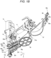
- FIGS. 1A , 1B , 2A , and 2B are perspective views illustrating examples of a screw driving machine according to the present illustrative embodiment.
- FIG. 1A illustrates a state where a magazine is in an open state and screws are not loaded
- FIG. 1B illustrates a state where the magazine is in the open state and the screws are loaded.
- FIG. 2A illustrates a state where the magazine is in a closed state and the screws are not loaded
- FIG. 2B illustrates a state where the magazine is in the closed state and the screws are loaded.
- FIGS. 3A and 3B are front views illustrating examples of the screw driving machine according to the present illustrative embodiment.
- FIG. 3A illustrates a state where the magazine is in the open state and the screws are loaded
- FIG. 3B illustrates a state where the magazine is in the closed state and the screws are loaded.
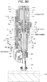
- FIG. 3C is a front sectional view illustrating an example of the screw driving machine according to the present illustrative embodiment.
- FIG. 4A is a side sectional view illustrating an example of the screw driving machine according to the present illustrative embodiment
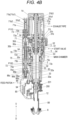
- FIG. 4B is a front sectional view illustrating the example of the screw driving machine according to the present illustrative embodiment
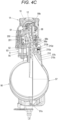
- FIG. 4C is a bottom sectional view illustrating the example of the screw driving machine according to the present illustrative embodiment.
- FIG. 5 is a perspective view illustrating an example of a screw coupling body.
- a plurality of screws 200 which are fasteners are coupled by a coupling band 201, and a screw coupling body 203 in a form of being wound in a spiral shape, for example, is used as a fastener coupling body.
- An unused screw coupling body 203 is fixed by a tape 204 such that the spiral shape is not deformed.
- the coupling band 201 may be formed by a plastic sheet having a predetermined shape that supports a shaft portion of the screw 200 or a nail, or may be formed by bonding a plurality of fasteners with a tape or by welding the plurality of fasteners with a metal wire.
- a screw driving machine 1A includes a fastening portion 3 that is driven by compressed air, causes a driver bit 2 to move in an axial direction, drives the screw 200 into a driven member 300, and then causes the driver bit 2 to rotate to tighten the screw 200.
- the fastening portion 3 includes a driving cylinder 30 that causes the driver bit 2 to move in the axial direction, and an air motor 31 that causes the driver bit 2 to rotate around an axis.
- the screw driving machine 1A includes a main valve 5, a start valve 6, and a trigger 60.
- the main valve 5 is configured to switch whether to supply the compressed air to the driving cylinder 30.
- the start valve 6 is configured to cause the main valve 5 to operate.
- the trigger 60 is configured to cause the start valve 6 to operate.
- the screw driving machine 1A includes an on-off valve 7 and a controller 70.
- the on-off valve 7 is configured to switch whether an operation of the air motor 31 is to be performed.
- the controller 70 is configured to cause the on-off valve 7 to operate.
- the screw driving machine 1A includes a contact arm 8.
- the contact arm 8 is configured to come into contact with the driven member 300, be movable in the axial direction along a driving direction of the screw 200, enable the start valve 6 to operate in cooperation with an operation of the trigger 60, and cause the controller 70 to operate.
- the screw driving machine 1A includes a screw feeding portion 9 and a magazine 90.
- the screw feeding portion 9 is configured to feed the screw coupling body 203 to a nose portion 12 to be described later.
- the magazine 90 is configured to accommodate the screw coupling body 203 to be fed by the screw feeding portion 9.
- the screw driving machine 1A includes a main body portion 10 and a handle portion 11.
- the handle portion 11 extends in a direction intersecting the main body portion 10.
- the nose portion 12 is provided on one side along an extending direction of the main body portion 10 extending along the axial direction of the driver bit 2.
- the driver bit 2 is configured to pass through the nose portion 12 when the screw 200 coupled by the coupling band 201 is supplied by the screw feeding portion 9.
- the one side along the extending direction of the main body portion 10 on which the nose portion 12 is provided is referred to as a lower side
- the other side along the extending direction of the main body portion 10 is referred to as an upper side.
- the magazine 90 is provided on the lower side of the handle portion 11 in a case where one side of the handle portion 11 along an extending direction of the main body portion 10 is directed toward the lower side.
- the nose portion 12 has an injection passage 12a and an injection port 12b.
- the screw 200 coupled by a coupling band 201 is supplied to the injection passage 12a.
- the injection port 12b is formed in one end portion along an extending direction of the injection passage 12a indicated by an arrow A.
- the screw 200 separated from the coupling band 201 is injected from the injection port 12b.
- the screw driving machine 1A includes a main chamber 13.
- the main chamber 13 is supplied with compressed air from an external air compressor (not illustrated).
- the main chamber 13 is provided in the handle portion 11 and on an outer periphery of the driving cylinder 30 connected to an inside of the handle portion 11 in the main body portion 10.
- Compressed air decompressed by a pressure reducing valve 13a is supplied to the main chamber 13.
- the screw driving machine 1A includes an exhaust pipe 14.
- the compressed air supplied to the driving cylinder 30, the air motor 31, and the like, is exhausted from the exhaust pipe 14.
- the exhaust pipe 14 is provided in the handle portion 11. The compressed air is exhausted from the exhaust pipe 14 via an exhaust filter 14a.
- the driving cylinder 30 is provided inside the main body portion 10 in a form of extending vertically.
- the driving cylinder 30 is provided with a driving piston 30a in a cylindrical internal space so as to be slidable.
- the driving piston 30a includes a seal portion 30b on an outer periphery thereof.
- the driving piston 30a is accommodated in the driving cylinder 30.
- the driving piston 30a partitions an interior of the driving cylinder 30 into a first chamber 30c and a second chamber 30d.
- a motor shaft 31a is attached to the driving piston 30a.
- the motor shaft 31a is driven by the air motor 31. In a state where the driving piston 30a is at the top dead center position, the driver bit 2 is connected to a first chamber 30c side.
- the driver bit 2 is detachably attached to the driving piston 30a via the motor shaft 31a in a form of protruding from the driving piston 30a toward the lower side.
- the motor shaft 31a is provided on a side opposite to the driver bit 2 with respect to the driving piston 30a.
- the motor shaft 31a is attached to the driving piston 30a in a form of protruding from the driving piston 30a toward the upper side.
- the compressed air is supplied from the main chamber 13 to the second chamber 30d.
- the driving piston 30a is pressed by an air pressure of the compressed air supplied to the second chamber 30d of the driving cylinder 30 and moves in a downward direction indicated by an arrow D to cause the driver bit 2 to move in the downward direction along the axial direction.
- the driver bit 2 and the motor shaft 31a move integrally with the driving piston 30a.
- the driver bit 2 that moves in the downward direction is guided by the nose portion 12, thereby driving the screw 200 supplied from the magazine 90 to the nose portion 12 into the driven member 300.
- the driver bit 2 rotates integrally with the motor shaft 31a to fasten the screw 200 driven into the driven member 300.
- the screw driving machine 1A includes a timer chamber 32 and a blowback chamber 33.
- the timer chamber 32 is supplied with the compressed air for causing the controller 70 to operate.
- the blowback chamber 33 causes the driving piston 30a moved to the bottom dead center position to return to the top dead center position and is supplied with the compressed air for causing the screw feeding portion 9 to operate.
- the timer chamber 32 and the blowback chamber 33 are provided on an outer peripheral side of the driving cylinder 30 inside the main body portion 10.
- the timer chamber 32 is in communication with a space in the driving cylinder 30 via a side hole flow path 32a of the driving cylinder 30.
- the blowback chamber 33 is in communication with the space in the driving cylinder 30 via a side hole flow path 33a of the driving cylinder 30.
- the compressed air is supplied by an operation of the driving piston 30a moving from the top dead center position to the bottom dead center position, and pressure increases according to a position of the driving piston 30a.
- the air motor 31 includes a rotor 31b1, a blade 31b2, and a motor housing 31c.
- the rotor 31b1 is configured to rotate the motor shaft 31a.
- the blade 31b2 is configured to receive a flow of air for causing the rotor 31b1 to rotate.
- the motor housing 31c rotatably supports the rotor 31b1 and is configured to generate the flow of air for causing the rotor 31b1 to rotate.
- rotation of the rotor 31b1 is transmitted to the motor shaft 31a via a speed reducer 31d.
- the speed reducer 31d is provided between the driving cylinder 30 and the air motor 31.
- the speed reducer 31d is configured by a planetary gear mechanism.
- the speed reducer 31d includes a sun gear 31e connected to the rotor 31b1, a plurality of planetary gears 31f meshing with the sun gear 31e, an outer gear 31g meshing with the planetary gears 31f, and a carrier 31h rotatably supporting the planetary gears 3 1f.
- the sun gear 31e, the planetary gears 31f, and the outer gear 31g are provided on the same surface in the axial direction of the driver bit 2.
- the carrier 31h is provided on the lower side of the sun gear 31e, the planetary gears 31f, and the outer gear 31g.
- the rotor 31b1 has a hollow structure in which a hole portion 31b3 is provided so as to penetrate from an upper end to a lower end in the axial direction along an upward direction indicated by an arrow U and the downward direction indicated by the arrow D.
- the motor shaft 31a is inserted into the hole portion 31b3 so as to be movable in the axial direction.
- the hole portion 31b3 is provided coaxially with a center of rotation of the rotor 31b1.
- the rotor 31b1 is provided with an engagement position connected to the sun gear 31e on the lower end thereof.
- the engagement position connected to the sun gear 31e is configured by a polygonal shaft, for example, a hexagonal shaft, and in the sun gear 31e, an engagement position connected to the rotor 31b1 is formed by a polygonal hole, for example, a hexagonal hole.
- the outer gear 31g has teeth formed on an inner peripheral surface of an annular member, and is non-rotatably fixed concentrically with the sun gear 31e.
- the planetary gear 31f is rotatably supported by the carrier 31h, and meshes with the sun gear 31e and the outer gear 31g in a form of being interposed between the sun gear 31e and the outer gear 31g. Accordingly, in the speed reducer 31d, when the sun gear 31e rotates as the rotor 31b1 rotates, the carrier 31h rotates at a predetermined reduction ratio while the planetary gear 31f rotates.
- the carrier 31h includes a plurality of gear rollers 31i that support the motor shaft 31a to be movable in the axial direction.
- the gear rollers 31i are rotatably supported by the carrier 31h in a disposition in which outer peripheral surfaces thereof are positioned on sides of a polygon, for example, a triangle, surrounding a center of rotation of the carrier 31h.
- the motor shaft 31a has a configuration in which a position in contact with the gear roller 31i is a flat surface.
- the motor shaft 31a has three flat surfaces in accordance with the disposition of the gear rollers 31i. Accordingly, the motor shaft 31a is supported at the center of rotation of the carrier 31h by the plurality of gear rollers 31i, and is movable in the axial direction by rotation of the gear rollers 31i.
- the air motor 31 is provided on the upper side of the main body portion 10.
- the motor shaft 31a is provided coaxially with the driver bit 2.
- the air motor 31 is provided coaxially with the driving cylinder 30 on a second chamber 30d side with respect to the driving cylinder 30, that is, on a side opposite to the lower side on which the nose portion 12 is provided in the main body portion 10 and on the upper side of the driving cylinder 30 along the axial direction of the driver bit 2.
- the air motor 31 ensures a space in which the motor shaft 31a moving in an up-down direction operates.
- the main valve 5 is vertically movably provided on an outer peripheral side of the driving cylinder 30.
- the main valve 5 is biased by a main valve spring 51 in the downward direction, which is a direction in which an air flow path 54 is closed.
- the compressed air is supplied, via the start valve 6, from the main chamber 13 to a main valve upper chamber 52 in which the main valve spring 51 is provided, and the main valve 5 is pressed in the downward direction by the air pressure of the compressed air.
- the compressed air is supplied from the main chamber 13 to a main valve lower chamber 53, and the main valve 5 is pressed in the downward direction by the air pressure of the compressed air
- the main valve 5 opens and closes the air flow path 54 connecting the main chamber 13, the driving cylinder 30, and the air motor 31.
- the air flow path 54 is provided between the driving cylinder 30 and the main valve 5 on an inner peripheral side of the main valve 5 and on the outer peripheral side of the driving cylinder 30, and is connected to the main valve lower chamber 53 via the main valve 5.
- the main valve 5 When the main valve 5 is not in operation, the main valve 5 is biased in the downward direction to be located at the bottom dead center position based on a relation, the relation being of a force of the main valve spring 51 and a balance between the air pressure of the compressed air supplied to the main valve upper chamber 52 and the air pressure of the compressed air supplied to the main valve lower chamber 53, thereby blocking the air flow path 54 between the main valve lower chamber 53 and the driving cylinder 30.
- the main valve 5 when the main valve 5 is in operation, the main valve 5 is pressed in the upward direction by the air pressure of the compressed air supplied from the main chamber 13 to the main valve lower chamber 53 when the main valve upper chamber 52 is in communication with the atmosphere via the start valve 6, thereby opening the air flow path 54 between the main valve lower chamber 53 and the driving cylinder 30.
- the start valve 6 includes a pilot valve 61, a valve stem 62, and a valve stem spring 63.
- the pilot valve 61 is configured to open and close the main valve upper chamber 52.
- the valve stem 62 is configured to cause the pilot valve 61 to operate.
- the valve stem spring 63 is configured to bias the pilot valve 61 in the upward direction and to bias the valve stem 62 in the downward direction.
- the pilot valve 61 is pressed in the downward direction due to the air pressure of the compressed air supplied from the main chamber 13. In addition, in the start valve 6, the pilot valve 61 is pressed in the upward direction due to the air pressure of the compressed air supplied from the main chamber 13 to a valve lower chamber 64.
- the pilot valve 61 is held at an upper position based on a relation between a balance of the air pressure of the compressed air and a force of the valve stem spring 63.
- the valve stem 62 moves in the upward direction
- the valve lower chamber 64 is in communication with the atmosphere, and thus the pilot valve 61 moves in the downward direction due to the air pressure of the compressed air.
- a passage through which the main valve upper chamber 52 communicates with the atmosphere is opened.
- the trigger 60 is provided on the lower side of the handle portion 11 and is rotatable about 60c as a fulcrum in response to an operation of an operator.
- the trigger 60 is biased in the direction separating from the valve stem 62 of the start valve 6 by a trigger spring 60d.
- the trigger 60 includes a contact lever 60a that causes the valve stem 62 of the start valve 6 to operate.
- the contact lever 60a is supported by the trigger 60 so as to be rotatable about a shaft 60b as a fulcrum.
- the contact lever 60a does not come into contact with the valve stem 62 only in a state where an operation of pulling the trigger 60 is performed.
- the contact lever 60a is pressed by an upper arm (not illustrated) of the contact arm 8 in the state where the operation of pulling the trigger 60 is performed, the valve stem 62 is caused to move in the upward direction. Accordingly, the start valve 6 is operated by a combination of an operation of the trigger 60 and an operation of being pressed by the contact arm 8.
- the contact arm 8 includes a lower arm 80 and an upper arm (not illustrated).
- the lower arm 80 is configured to come into contact with the driven member 300.
- the upper arm (not illustrated) is configured to cause the contact lever 60a of the trigger 60 to operate.
- the lower arm 80 is supported by the nose portion 12 so as to be movable in the up-down direction.
- the lower arm 80 is biased in the downward direction by a biasing member (not illustrated).
- the screw driving machine 1A includes a tightening depth adjusting portion 86.
- the tightening depth adjusting portion 86 defines an upper fulcrum position of the lower arm 80 and is configured to cause the first control valve 72 to operate when the lower arm 80 moves to the upper fulcrum position.
- the tightening depth adjusting portion 86 includes an adjusting portion main body 86a and an abutting portion 86b whose protrusion height with respect to the adjusting portion main body 86a is adjustable.
- the tightening depth adjusting portion 86 is supported so as to be movable along moving directions of the lower arm 80 indicated by the arrows U and D, and is biased in the downward direction indicated by the arrow D by a biasing member 86c such as a coil spring.
- the tightening depth adjusting portion 86 has a configuration in which the adjusting portion main body 86a and the abutting portion 86b are joined by, for example, screwing a male screw and a female screw.
- a dial portion 86d for causing the adjusting portion main body 86a to rotate is exposed to an outside of the main body portion 10.
- the adjusting portion main body 86 is caused to rotate by an operation of the dial portion 86d, whereby a protrusion amount of the abutting portion 86b with respect to the adjusting portion main body 86a is switched, and an entire length of the tightening depth adjusting portion 86 is changed.
- the abutting portion 86b faces the lower arm 80.
- the abutting portion 86b and the lower arm 80 are separated from each other in a state where the lower arm 80 moves to the bottom dead center position.
- the tightening depth adjusting portion 86 when the lower arm 80 moves in the upward direction as indicated by the arrow U from the bottom dead center position, the lower arm 80 comes into contact with the abutting portion 86b.
- the tightening depth adjusting portion 86 When the tightening depth adjusting portion 86 is pressed up by the lower arm 80 moving in the arrow U direction and moves to a position where the adjusting portion main body 86a comes into contact with a movement regulating portion 86e, the tightening depth adjusting portion 86 regulates the lower arm 80 from further moving in the arrow U direction.
- the protrusion amount of the abutting portion 86b with respect to the adjusting portion main body 86a is switched by the operation of the dial portion 86d, and the entire length of the tightening depth adjusting portion 86 is changed.
- the top dead center position of the lower arm 80 moves.
- a protrusion amount of the driver bit 2 with respect to a lower end surface of the lower arm 80 changes, the driver bit 2 being moved to the bottom dead center position with respect to the lower end surface of the lower arm 80, and a tightening depth of the screw 200 with respect to the driven member 300 changes.
- the on-off valve 7 is vertically movably supported by an on-off valve cylinder 73 provided in the motor housing 31c.
- an on-off valve lower chamber 73a is provided on the lower side of the on-off valve 7 indicated by the arrow D
- an on-off valve upper chamber 73b is provided on the upper side of the on-off valve 7 indicated by the arrow U.
- the on-off valve 7 is operated due to the compressed air supplied from the main chamber 13 and, in a state where the compressed air is not supplied to the on-off valve upper chamber 73b, the on-off valve 7 moves in the upward direction indicated by the arrow U due to the compressed air supplied to the on-off valve lower chamber 73a.
- the on-off valve upper chamber 73b moves in the downward direction as indicated by the arrow D.
- the on-off valve 7 is configured to open and close the air flow path 74 connected to the air motor 31 by moving in the up-down direction.
- the air flow path 74 is in communication with the air flow path 54 on a downstream side of the main valve 5.
- a flow of air between the main chamber 13 and the air motor 31 is blocked when the on-off valve 7 moves in the downward direction and is closed.
- the on-off valve 7 moves in the upward direction and opens, communication between the main chamber 13 and the air motor 31 is established.
- the on-off valve 7 is provided on a side portion of the air motor 31.
- the controller 70 includes a control valve cylinder 75, a first control valve 72, a communication passage 75c, and a second control valve 71.
- the first control valve 72 is accommodated in the control valve cylinder 75 and partitions an inside of the control valve cylinder 75 into a third chamber 75a and a fourth chamber 75b.
- the communication passage 75c allows the inside of the driving cylinder 30 and the third chamber 75a in the control valve cylinder 75 to communicate with each other via the timer chamber 32.
- the second control valve 71 is located on an arrow U direction side with respect to the first control valve 72 and is disposed away from the first control valve 72.
- the controller 70 includes a first biasing member 72b and a second biasing member 71a.
- the first biasing member 72b is a first biasing portion configured to bias the first control valve 72 in an arrow D direction.
- the second biasing member 71a is a second biasing portion configured to bias the second control valve 71 in an arrow D direction.
- the third chamber 75a is provided on the lower side of the first control valve 72 indicated by the arrow D, and the fourth chamber 75b is provided on the upper side of the first control valve 72 indicated by the arrow U.
- the third chamber 75a is in communication with the timer chamber 32 via the communication passage 75c, and is in communication with the space in the driving cylinder 30 via the timer chamber 32.
- the third chamber 75a is in communication with an outside of a body of the screw driving machine 1A via an exhaust passage 75d.
- the first control valve 72 is vertically movably supported by the control valve cylinder 75 along the upward direction indicated by the arrow U and the downward direction indicated by the arrow D.
- a rod-shaped coupling portion 72a extending in the up-down direction is coupled in a form protruding in the upward direction indicated by the arrow U.
- the first control valve 72 is biased in the arrow D direction by the first biasing member 72b such as a coil spring.
- the first control valve 72 faces the adjusting portion main body 86a of the tightening depth adjusting portion 86.
- the first control valve 72 is configured to be movable to a standby position P100 which is the bottom dead center position by moving in the downward direction indicated by the arrow D, and is configured to be movable to a later-described operation completion position which is the top dead center position by moving in the upward direction indicated by the arrow U.
- the first control valve 72 moves to the standby position P100 by being biased in the arrow D direction by the first biasing member 72b.
- the first control valve 72 includes a seal portion 72c that opens and closes the exhaust passage 75d.
- the seal portion 72c moves to a position to open the exhaust passage 75d, and the third chamber 75a of the control valve cylinder 75 is in communication with the outside of the body of the screw driving machine 1A via the exhaust passage 75d.
- the seal portion 72c moves to a position to close the exhaust passage 75d.
- the first control valve 72 standing by at the standby position P100 is pressed and operated by the lower arm 80 via the tightening depth adjusting portion 86, and moves from the standby position P100 to the pressure control start position.
- the first control valve 72 moves to the pressure control start position
- the first control valve 72 is operated due to the compressed air supplied from the timer chamber 32 and moves from the pressure control start position to the operation completion position.
- the first control valve 72 presses the second control valve 71 via the coupling portion 72a to cause the second control valve 71 to operate.
- the second control valve 71 is configured by a rod-shaped member extending in the up-down direction, and is vertically movably supported with respect to the on-off valve 7.
- the second control valve 71 moves to a standby position P 110 by being biased in the arrow D direction by the second biasing member 71a.
- the second control valve 71 is operated by being pressed by the first control valve 72.
- the second control valve 71 is movable from the standby position P110 to the later-described operation completion position and is configured to cause the on-off valve 7 to operate by switching whether to supply the compressed air to the on-off valve upper chamber 73b of the on-off valve cylinder 73.
- the controller 70 includes an adjustment member 71b configured to adjust a biasing force of the second biasing member 71a.
- the adjustment member 71b configures an adjustment portion. For example, a screw is formed on an outer periphery of the adjustment member 71b, and a length of the second biasing member 71a in an expansion and contraction direction is adjusted by adjusting a tightening amount of the screw.
- the screw feeding portion 9 includes a feeding member 91 and a feed piston 92.
- the feeding member 91 is configured to feed the screw coupling body 203.
- the feed piston 92 is configured to cause the feeding member 91 to operate.
- the feeding member 91 is supported so as to be movable in a direction approaching and a direction separating from the injection passage 12a of the nose portion 12.
- the feeding member 91 is configured to feed the screw 200, which is locked by the coupling band 201 and is coupled by the coupling band 201, to the injection passage 12a.
- the feed piston 92 is coupled to the feeding member 91 and is provided in a feed cylinder 93 so as to be slidable.
- the feed cylinder 93 is connected to the blowback chamber 33 via a feed flow path 94, and is supplied with compressed air from the blowback chamber 33.
- the feed piston 92 is operated due to an air pressure of the compressed air supplied from the blowback chamber 33 to cause the feeding member 91 to move in the direction separating from the injection passage 12a.
- a biasing member 95 such as a coil spring in the direction approaching the injection passage 12a and the air pressure in the feed cylinder 93 decreases
- the feed piston 92 causes the feeding member 91 to move in the direction approaching the injection passage 12a by being biased by the biasing member 95.
- the magazine 90 is provided on the lower side of the handle portion 11 and is coupled to the nose portion 12.
- the screw coupling body 203 illustrated in FIG. 5 is accommodated in the magazine 90.
- the screw driving machine 1A has a supply passage 96a.
- the supply passage 96a connects the injection passage 12a and the magazine 90.
- the screw coupling body 203 is fed through the supply passage 96a along a first direction indicated by an arrow B intersecting with the extending direction of the injection passage 12a.
- the supply passage 96a is formed by a part of a member configuring the magazine 90 and a part of a member configuring the nose portion 12.
- the supply passage 96a extends along the first direction indicated by the arrow B between the injection passage 12a and a space in the magazine 90 in which the screw coupling body 203 in a form of being wound in a spiral shape is accommodated.
- the screw driving machine 1A has a discharge port 12c.
- the discharge port 12c connects the injection passage 12a and an outside of the nose portion 12.
- the coupling band 201, from which the screw 200 has been injected, is discharged through the nose portion 12 along the first direction indicated by the arrow B.
- the discharge port 12c is located on a side opposite to the supply passage 96a via the injection passage 12a on an extension line of the supply passage 96a.
- the discharge port 12c is formed by providing an opening having a size through which the coupling band 201 can pass in a part of a surface facing the first direction indicated by the arrow B.
- a side portion of the magazine 90, a side portion of the supply passage 96a, a side portion of the injection passage 12a, and a side portion of the discharge port 12c are opened, the side portions facing a second direction indicated by an arrow C.
- the second direction intersects with the direction, in which the injection passage 12a extends and which is indicated by the arrow A, and the first direction indicated by the arrow B.
- the screw driving machine 1A includes a magazine cap portion 97.
- the magazine cap portion 97 includes a tip portion on an injection passage 12a side and a base end portion opposite to the tip portion in a direction intersecting with the injection passage 12a. By the tip portion rotating in a direction separating from and approaching the magazine 90 with the base end portion as a fulcrum, the magazine cap portion 97 is configured to open and close the magazine 90 by the tip portion separating from and approaching the magazine 90.
- the magazine cap portion 97 is configured to cover a part of the opened side portion of the magazine 90 and the opened side portion of the supply passage 96a in an openable and closable manner.
- the screw driving machine 1A includes a door portion 98.
- the door portion 98 is integrally coupled to the magazine cap portion 97.
- the door portion 98 is configured to cover a part of the opened side portion of the injection passage 12a, the opened side portion of the discharge port 12c, and the opened side portion of the supply passage 96a in an openable and closable manner.
- the magazine cap portion 97 is an example of a lid portion.
- the magazine cap portion 97 has a shape that extends from a convex portion which can cover the screw coupling body 203 in a form of being wound in a spiral shape toward a side where the nose portion 12 is provided and covers a part of the supply passage 96b.
- an end portion on a side opposite to a side to which the door portion 98 is coupled is supported by the magazine 90 via a support shaft 97a, so that the magazine cap portion 97 is rotatable with respect to the magazine 90 with the support shaft 97a as a fulcrum.
- the biasing member such as a torsion coil spring is inserted into the support shaft 97a, and the magazine cap portion 97 is biased in an opening direction with respect to the magazine 90.
- the magazine cap portion 97 may be configured not to be biased by the biasing member in the opening direction with respect to the magazine 90.
- the door portion 98 is an example of the lid portion.
- the door portion 98 is supported by the magazine cap portion 97 via a coupling shaft 98a and is rotatable with respect to the magazine cap portion 97 with the coupling shaft 98a as a fulcrum.
- An axial direction of the coupling shaft 98a is a direction intersecting the first direction that is indicated by the arrow B.
- An axial direction of the support shaft 97a via which the magazine cap portion 97 is supported by the magazine 90 and the axial direction of the coupling shaft 98a via which the door portion 98 is supported by the magazine cap portion 97 are parallel.
- the magazine cap portion 97 and the door portion 98 are changeable between a linearly extending form and a bent form by relative rotation thereof with the coupling shaft 98a as a fulcrum.
- a biasing member 98b such as a torsion coil spring is inserted into the coupling shaft 98a, and the magazine cap portion 97 and the door portion 98 are biased in a bending direction.
- the biasing member 98b is an example of a biasing portion.
- the magazine cap portion 97 and the door portion 98 are configured to open and close the side portion of the magazine 90, the side portion of the supply passage 96a, the side portion of the injection passage 12a, and the side portion of the discharge port 12c by an integral rotating operation with the support shaft 97a as a fulcrum.
- the screw driving machine 1A when the magazine cap portion 97 and the door portion 98 are in the open state, the side portion of the magazine 90, the side portion of the supply passage 96a, the side portion of the injection passage 12a, and the side portion of the discharge port 12c are exposed.
- the side portion of the magazine 90, the side portion of the supply passage 96a, the side portion of the injection passage 12a, and the side portion of the discharge port 12c open in a form of being connected along the first direction indicated by the arrow B.
- the screw driving machine 1A has an opening portion 12d in the side portion of the injection passage 12a and the side portion of the discharge port 12c.
- the opening portion 12d is formed in a form of connecting an opening in the side portion of the injection passage 12a and an opening in the side portion of the discharge port 12c along the first direction indicated by the arrow B.
- the opening portion 12d is exposed when the magazine cap portion 97 and the door portion 98 are in the open state.
- the door portion 98 exposes the opening portion 12d in a state where the discharge port 12c is opened.
- the screw driving machine 1A includes a plurality of engaging portions configured to hold the magazine cap portion 97 and the door portion 98 in a closed state where the magazine 90 is closed.
- a first engaging portion 99a and a second engaging portion 99b that hold the magazine cap portion 97 and the door portion 98 in the closed state are provided.
- the first engaging portion 99a is provided on the door portion 98 on a side that is close to the coupling shaft 98a coupled to the magazine cap portion 97.
- the first engaging portion 99a includes an engaging convex portion 99a2, an operation portion 99a3, and a biasing member 99a4.
- the engaging convex portion 99a2 is configured to enter an engaged concave portion 99a1 provided in the main body portion 10.
- the operation portion 99a3 is configured to receive an operation of inserting and removing the engaging convex portion 99a2 into and from the engaged concave portion 99a1.
- the biasing member 99a4 such as a coil spring is configured to bias the first engaging portion 99a in a direction in which the engaging convex portion 99a2 enters the engaged concave portion 99a1.
- the biasing member 99a4 is an example of a biasing portion.
- the first engaging portion 99a is displaced between a holding position and a releasing position.
- the first engaging portion 99a holds the door portion 98 and the magazine cap portion 97 in the closed state by the engaging convex portion 99a2 being biased by the biasing member 99a4 to enter the engaged concave portion 99a1 and being engaged with the main body portion 10.
- engagement with the main body portion 10 is released by separating the engaging convex portion 99a2 from the engaged concave portion 99a1 by the operation of the operation portion 99a3, whereby the first engaging portion 99a allows the door portion 98 and the magazine cap portion 97 to be openable and closable.
- the second engaging portion 99b is an example of an engaging portion.
- the second engaging portion 99b is provided on the nose portion 12.
- the second engaging portion 99b is provided on both sides of the discharge port 12c along the extending direction of the injection passage 12a indicated by the arrow A. That is, the second engaging portion 99b is provided to face both sides of the door portion 98 along the extending direction of the injection passage 12a indicated by the arrow A with respect to the door portion 98 in the closed state.
- the second engaging portion 99b is provided in the vicinity of the injection passage 12a.
- the second engaging portion 99b is entirely or partially provided on a side closer to the nose portion 12 than a position H1 of the most protruding portion in the second direction indicated by the arrow C in the door portion 98 in the closed state. Providing the second engaging portion 99b at such a position is referred to as providing the second engaging portion 99b in the vicinity of the injection passage 12a.
- the door portion 98 has an engaging convex portion 99c engageable with the second engaging portion 99b at a tip portion 98c of the door portion 98.
- the second engaging portion 99b has an engaging concave portion 99d with which the engaging convex portion 99c engages.
- the engaging convex portion 99c is an example of a convex portion.
- the engaging convex portion 99c is provided on both sides of the door portion 98 along the extending direction of the injection passage 12a indicated by the arrow A.
- the engaging convex portion 99c has a columnar shape protruding from the door portion 98 along the axial directions of the support shaft 97a and the coupling shaft 98a.
- the engaging concave portion 99d is an example of a concave portion.
- the engaging concave portion 99d is formed by a groove portion that extends along the first direction indicated by the arrow B and has a shape into which the engaging convex portion 99c is insertable.
- the engaging concave portion 99d is opened on a side facing the magazine 90 on a side opposite to the first direction, allowing the engaging convex portion 99c to be inserted and removed.
- a guide portion 99e connected to the engaging concave portion 99d is provided on a side of the engaging concave portion 99d that is close to the nose portion 12.
- the guide portion 99e is an extension portion of a surface on the side of the engaging concave portion 99d that is close to the nose portion 12, and extends along the first direction.
- the second engaging portion 99b has an introduction portion 99f on a side of the engaging concave portion 99d that is far from the nose portion 12.
- the introduction portion 99f is an end portion on the side of the engaging concave portion 99d that is far from the nose portion 12.
- the introduction portion 99f is formed at a position where the introduction portion 99f enters in the first direction more than the guide portion 99e.
- the magazine cap portion 97 and the door portion 98 change between the linearly extending form and the bent form by the relative rotation thereof with the coupling shaft 98a as a fulcrum, thereby changing a distance from the support shaft 97a to the engaging convex portion 99c.
- a length from the support shaft 97a to the guide portion 99e is formed to be longer than the distance from the support shaft 97a to the engaging convex portion 99c when the magazine cap portion 97 and the door portion 98 change to the bent form by the relative rotation thereof with the coupling shaft 98a as a fulcrum. Accordingly, when the magazine cap portion 97 and the door portion 98 change to the bent form, the guide portion 99e is located on a rotation trajectory of the engaging convex portion 99c around the support shaft 97a.
- a length from the support shaft 97a to the introduction portion 99f is formed to be shorter than the distance from the support shaft 97a to the engaging convex portion 99c when the magazine cap portion 97 and the door portion 98 change to the bent form by the relative rotation thereof with the coupling shaft 98a as a fulcrum. Accordingly, when the magazine cap portion 97 and the door portion 98 change to the bent form, the introduction portion 99f is located outside the rotation trajectory of the engaging convex portion 99c around the support shaft 97a.
- the length from the support shaft 97a to the guide portion 99e is formed to be shorter than the distance from the support shaft 97a to the engaging convex portion 99c when the magazine cap portion 97 and the door portion 98 change to the linearly extending form by the relative rotation thereof with the coupling shaft 98a as a fulcrum. Accordingly, in a state where the magazine cap portion 97 and the door portion 98 change to the bent form by the relative rotation thereof with the coupling shaft 98a as a fulcrum, even when the magazine cap portion 97 and the door portion 98 rotate with the support shaft 97a as a fulcrum, the engaging convex portion 99c does not come into contact with the introduction portion 99f.
- the engaging convex portion 99c is in contact with the guide portion 99e.
- the magazine cap portion 97 and the door portion 98 may be configured as a lid portion that is fixedly integrated, instead of being configured to be connected in a movable form via the coupling shaft 98a.
- a side opposite to a side on which a portion corresponding to the door portion is provided is supported such that the lid portion is openable and closable by a rotating operation with the support shaft as a fulcrum with respect to the magazine 90.
- the screw driving machine 1A includes a screw detector 210 configured to detect presence or absence of the screw 200 (screw coupling body 203).
- the screw detector 210 is an example of a consumable detector.
- the screw detector 210 is supported by the magazine cap portion 97 via a shaft 210a.
- the screw detector 210 includes a detection terminal 210b that is provided on one side across the shaft 210a.
- the detection terminal 210b is contactable with the screw coupling body 203 passing through the supply passage 96a.
- the screw detector 210 includes a confirmation portion 210c which is provided on the other side across the shaft 210a.
- the confirmation portion 210c is configured to protrude to an outside of the magazine cap portion 97 from a window portion 97b provided in the magazine cap portion 97 and to be retracted to an inside of the magazine cap portion 97.
- the screw detector 210 includes a biasing member 210d such as a coil spring configured to bias the detection terminal 210b in a direction of the supply passage 96a.
- the screw detector 210 when the screw coupling body 203 is accommodated in the magazine 90, a portion pulled out from a state of being wound in a spiral shape is passed through the supply passage 96a, and the magazine cap portion 97 and the door portion 98 are closed, the detection terminal 210b comes into contact with the screw coupling body 203 and is pressed. Accordingly, the screw detector 210 rotates with the shaft 210a as a fulcrum, and the confirmation portion 210c is retracted from the window portion 97b of the magazine cap portion 97 to the inside of the magazine cap portion 97.
- FIG. 6A is a cross-sectional view illustrating an example of opening and closing operations of a magazine cap portion and a door portion
- FIG. 6B is a perspective view illustrating the example of the opening and closing operations of the magazine cap portion and the door portion. An example of opening and closing operations of the magazine cap portion 97 and the door portion 98 will be described.
- the engaging concave portion 99d causes the door portion 98, which is bent with the coupling shaft 98a as a fulcrum with respect to the magazine cap portion 97, to extend linearly against a biasing force of the biasing member 98b.
- the first engaging portion 99a is engaged with the main body portion 10 and moves to the holding position that holds the door portion 98 and the magazine cap portion 97 in the closed state.
- the magazine cap portion 97 and the door portion 98 are in the closed state, the magazine cap portion 97 and the door portion 98 are in the linearly extending form, and a side of the door portion 98 that is close to the coupling shaft 98a coupled to the magazine cap portion 97 is held in the closed state by the first engaging portion 99a.
- the tip portion 98c which is a side that is close to the nose portion 12 opposite to the coupling shaft 98a coupled to the magazine cap portion 97 in the door portion 98, is held in the closed state by the second engaging portion 99b by the engagement between the engaging convex portion 99c and the engaging concave portion 99d.
- the first engaging portion 99a In order to open the magazine cap portion 97 and the door portion 98, the first engaging portion 99a is moved to the releasing position that releases the engagement with the main body portion 10 to open and close the door portion 98 and the magazine cap portion 97.
- the magazine cap portion 97 and the door portion 98 change to the bent form by the relative rotation thereof with the coupling shaft 98a as a fulcrum by biasing of the biasing member (not illustrated).
- the engaging convex portion 99c of the door portion 98 moves to an outside of the introduction portion 99f and is guided by the guide portion 99e, thereby moving to a position where the engaging convex portion 99c is separated from the engaging concave portion 99d on the nose portion 12 side.
- the magazine cap portion 97 and the door portion 98 can be in the open state by the rotating operation with the support shaft 97a as a fulcrum.
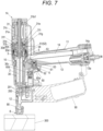
- FIG. 7 is a side sectional view of the screw driving machine illustrating an example of an operation of driving a screw into a driven member and tightening the screw
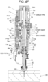
- FIGS. 8A , 8B , 8C , 8D , 8E , 8F , and 8G are front sectional views of the screw driving machine illustrating examples of an operation of driving the screw into the driven member and tightening the screw
- FIG. 9 is a bottom sectional view of the screw driving machine illustrating an example of a state where the screw in the magazine is used.
- the operator holds the handle portion 11, and the contact arm 8 is pressed against the driven member 300.
- the screw driving machine 1A when the contact arm 8 is pressed against the driven member 300, the lower arm 80 moves in the upward direction due to the relative movement with respect to the main body portion 10.
- the upper arm (not illustrated) of the contact arm 8 moves to a position where the contact lever 60a of the trigger 60 is caused to operate. Accordingly, when the operation of pulling the trigger 60 is performed, as illustrated in FIG. 7 , the contact lever 60a presses the valve stem 62 of the start valve 6, and the start valve 6 is operated.
- the main valve 5 When the start valve 6 is operated, the main valve 5 is operated as illustrated in FIG. 8B , and the compressed air is supplied to the driving cylinder 30 and the on-off valve 7.
- the driving piston 30a to which the driver bit 2 is attached is pressed by the air pressure, and as illustrated in FIG. 8C , the driver bit 2 (driving piston 30a) moves in the downward direction from the top dead center position to the bottom dead center position, and the screw 200 is driven into the driven member 300.
- the driver bit 2 driving piston 30a
- the compressed air in the blowback chamber 33 is supplied from the feed flow path 94 of the screw feeding portion 9 to the feed piston 92.
- the feeding member 91 moves in a direction separating from the injection passage 12a.
- the feeding member 91 is separated from the coupling band 201, and the screw coupling body 203 is not fed.
- the driver bit 2 rotates, and as illustrated in FIG. 8D , the screw 200 driven into the driven member 300 is tightened.
- the main body portion 10 further moves in the downward direction following the tightening of the screw 200.
- the main body portion 10 By the operation of pressing the contact arm 8 against the driven member 300, the main body portion 10 further moves in the downward direction following the tightening of the screw 200, and the lower arm 80 moves relatively in the upward direction.
- the tightening depth adjusting portion 86 is pressed in the upward direction.
- the tightening depth adjusting portion 86 is pressed up by the lower arm 80 moving in the arrow U direction and the tightening depth adjusting portion 86 moves to a position where the tightening depth adjusting portion 86 comes into contact with the movement regulating portion 86e, the lower arm 80 is regulated from further moving in the upward direction.
- a position of the lower arm 80 regulated by the movement to the position where the tightening depth adjusting portion 86 comes into contact with the movement regulating portion 86e becomes the upper fulcrum position of the lower arm 80.
- the lower arm 80 presses the first control valve 72 in the upward direction via the tightening depth adjusting portion 86, and the first control valve 72 moves from the standby position P100 illustrated in FIG. 8A and the like to a pressure control start position P101.
- the third chamber 75a is normally in communication with the space in the driving cylinder 30 via the communication passage 75c and the side hole flow path 32a of the driving cylinder 30.
- the seal portion 72c of the first control valve 72 is at a position where the exhaust passage 75d is opened, and the third chamber 75a of the control valve cylinder 75 is in communication with the outside of the body of the screw driving machine 1A via the exhaust passage 75d. Accordingly, even when the compressed air is supplied from the timer chamber 32 to the third chamber 75a of the control valve cylinder 7 5, the third chamber 75a is maintained at atmospheric pressure, and the first control valve 72 does not operate with the air pressure.
- the seal portion 72c of the first control valve 72 closes the exhaust passage 75d.
- pressure in the control valve cylinder 75 increases due to the air pressure of the compressed air supplied from the timer chamber 32 to the third chamber 75a of the control valve cylinder 75.
- the first control valve 72 is operated due to the air pressure, and as illustrated in FIG. 8F , the first control valve 72 further moves in the upward direction.
- the first control valve 72 presses the second control valve 71 in the upward direction.
- the second control valve 71 moves to an operation completion position Pill by movement of the first control valve 72 to an operation completion position P102, the compressed air is supplied to the on-off valve upper chamber 73b of the on-off valve cylinder 73 which is a space on the upper side of the on-off valve 7.
- the operator weakens the force for pressing the contact arm 8 against the driven member 300 and causes the main body portion 10 to move in a direction separating from the driven member 300.
- the supply of the compressed air to the feed piston 92 is stopped.
- the feeding member 91 coupled to the feed piston 92 moves in a direction approaching the injection passage 12a by the biasing of the biasing member 95.
- the feeding member 91 is engaged with the coupling band 201, and a next screw 200 is fed to the injection passage 12a.
- the coupling band 201 after the screw 200 is injected is discharged from the discharge port 12c to the outside of the nose portion 12.
- the screw coupling body 203 pulled out from a portion wound in a spiral shape in the magazine 90 is passed through the supply passage 96a.
- the screw coupling body 203 comes into contact with the detection terminal 210b until a terminal of the screw coupling body 203 passes through the detection terminal 210b of the screw detector 210.
- the detection terminal 210b of the screw detector 210 comes into contact with the screw coupling body 203 and is pressed as illustrated in FIG. 4C . Accordingly, the screw detector 210 rotates with the shaft 210a as a fulcrum, and the confirmation portion 210c is retracted from the window portion 97b of the magazine cap portion 97 to the inside of the magazine cap portion 97.
- the operator can confirm that the predetermined number of screws 200 remain by visually checking the window portion 97b of the magazine cap portion 97 or by touching with a hand.
- the detection terminal 210b of the screw detector 210 is separated from the screw coupling body 203. Accordingly, the screw detector 210 is biased by the biasing member 210d and rotates with the shaft 210a as a fulcrum, and the confirmation portion 210c protrudes from the window portion 97b of the magazine cap portion 97 to an outside of the magazine cap portion 97.
- the operator can confirm that the number of remaining screws 200 is equal to or less than the predetermined number before the screws 200 are removed by visually checking the confirmation portion 210c protruding from the window portion 97b of the magazine cap portion 97 or by touching with a hand. Accordingly, it is possible to select an executable operation according to the remaining number of the screws 200.
- the magazine cap portion 97 and the door portion 98 are integrally coupled to open and close the magazine 90.
- the side portion of the magazine 90, the side portion of the supply passage 96a, the side portion of the injection passage 12a, and the side portion of the discharge port 12c are exposed. Accordingly, in a case where the screw coupling body 203 is to be loaded, a task of accommodating the screw coupling body 203 wound in a spiral shape in the magazine 90 and inserting the screw coupling body 203 pulled out from the portion wound in a spiral shape into the supply passage 96a from the lateral side can be easily performed. In addition, the task of inserting the screw coupling body 203 into the supply passage 96a can be easily performed by aligning a position of the screw 200 with the injection passage 12a.
- a configuration is provided in which a magazine cap portion provided in a magazine and a door portion provided in a nose portion are opened and closed, respectively. Therefore, the door portion provided in the nose portion is configured to be opened and closed by a rotating operation with a shaft provided in the nose portion as a fulcrum.
- the magazine cap portion 97 and the door portion 98 are integrally coupled to open and close the magazine 90.
- the end portion on the side opposite to the side to which the door portion 98 is coupled is supported by the magazine 90 via the support shaft 97a.
- the opening portion 12d when the magazine cap portion 97 and the door portion 98 are in the open state, the opening portion 12d is exposed, the opening portion 12d being formed in a form in which the opening in the side portion of the injection passage 12a and the opening in the side portion of the discharge port 12c are connected along the first direction indicated by the arrow B.
- the opening portion 12d is exposed in a form of being connected to the discharge port 12c.
- the tape 204 of a portion protruding out from a tip of the screw coupling body 203 can be inserted into the opening portion 12d from the lateral side without peeling off the entire tape 204 fixing the screw coupling body 203.
- the screw coupling body 203 before injection of the screw 200 pulled out from the portion wound in a spiral shape can be taken out from the lateral side of the supply passage 96a. Further, the coupling band 201 after the screw 200 is injected can be taken out from the lateral side of the opening portion 12d. Accordingly, in the case where the screw coupling body 203 in use is to be taken out, the screw coupling body 203 can be taken out from the magazine 90 without separating the coupling band 201 after the screw 200 is injected.
- the coupling band 201 after the screw 200 is injected can be inserted into the opening portion 12d from the lateral side. Accordingly, in the case where the screw coupling body 203 in use is to be loaded, the screw coupling body 203 can be loaded into the magazine 90 without separating the coupling band 201 after the screw 200 is injected.
- the openings in the side portion of the magazine 90, the side portion of the supply passage 96a, the side portion of the injection passage 12a, and the side portion of the discharge port 12c are covered with the magazine cap portion 97 and the door portion 98, and the opening portion 12d is covered with the magazine cap portion 97 and the door portion 98.
- the door portion 98 covers the opening portion 12d in the state where the discharge port 12c is opened. Accordingly, the supply passage 96b can be formed in a form in which the coupling band 201 after the screw 200 is injected can be discharged from the discharge port 12c to the outside of the nose portion 12.
- the magazine cap portion 97 and the door portion 98 are integrally coupled by the coupling shaft 98a, the magazine cap portion 97 and the door portion 98 are integrally opened, and the opening portion 12d is exposed, so that the screw coupling body 203 is easily loaded.
- the screw driving machine 1A when the magazine cap portion 97 and the door portion 98 are in the closed state, the side of the door portion 98 that is close to the coupling shaft 98a coupled to the magazine cap portion 97 is held in the closed state by the first engaging portion 99a.
- the side that is close to the nose portion 12 is held in the closed state by the second engaging portion 99b by the engagement between the engaging convex portion 99c and the engaging concave portion 99d.
- the door portion 98 can ensure the same strength as that of a door portion in a configuration in which a magazine cap portion and a door portion are separately opened and closed.
- the magazine cap portion 97 and the door portion 98 are integrally coupled by the coupling shaft 98a, so that the magazine cap portion 97 and the door portion 98 change between the linearly extending form and a bent form by the relative rotation thereof with the coupling shaft 98a as a fulcrum.
- the screw driving machine 1A is configured such that the second engaging portion 99b includes the engaging convex portion 99c in the door portion 98 and the engaging concave portion 99d in the nose portion 12, and the guide portion 99e extending from the engaging concave portion 99d to the side facing the magazine 90 is provided, allowing the engaging convex portion 99c to be inserted into and removed from the engaging concave portion 99d using the guide portion 99e as a guide.
- the engaging convex portion 99c enters the engaging concave portion 99d using the guide portion 99e as a guide, the engaging convex portion 99c further moves along the engaging concave portion 99d, the engaging convex portion 99c and the engaging concave portion 99d engage with each other, and the magazine cap portion 97 and the door portion 98 are brought into the closed state.
- the magazine cap portion 97 and the door portion 98 can be integrally opened and closed, the operation of opening and closing the magazine 90 by the magazine cap portion 97 and the door portion 98 is easy. In addition, it is possible to prevent generation of a load due to the engagement between the engaging convex portion 99c and the engaging concave portion 99d by the operation of bringing the magazine cap portion 97 and the door portion 98 into the closed state.
- the screw driving machine operated by the air pressure as a tool is described as an example, but the present invention is also applicable to a screw driving machine driven by electricity, a nail driving machine operated by air pressure using a nail as a fastener, a nail driving machine driven by electricity, and the like.
Landscapes
- Engineering & Computer Science (AREA)
- Mechanical Engineering (AREA)
- Portable Nailing Machines And Staplers (AREA)
- Details Of Spanners, Wrenches, And Screw Drivers And Accessories (AREA)
Abstract
Description
- The present disclosure relates to a handheld tool that includes a magazine accommodating a fastener and is configured to inject consumables accommodated in the magazine.
- A handheld tool that injects a fastener such as a screw or a nail includes a magazine that accommodates the fastener. The magazine accommodates a fastener coupling body in which a plurality of fasteners are coupled by a coupling band. In such a handheld tool, a nose portion from which the fastener is injected, a magazine cap portion provided in the magazine in order to allow the fastener coupling body to be loaded into the magazine, and a door portion provided in the nose portion are configured to be opened and closed, respectively (for example, see
JP6070946B - In a related-art handheld tool in which a door portion is provided in a nose portion, a part of a portion on a lateral side of an injection passage of a fastener provided in the nose portion is formed by the door portion. In addition, in the handheld tool using fasteners coupled by a coupling band, a discharge port for discharging the coupling band after the fasteners are injected is provided in the nose portion, and a part of a portion on a lateral side of the discharge port is formed by the door portion. In contrast, in the related art, the door portion provided in the nose portion is opened and closed by a rotating operation with a shaft provided in the nose portion as a fulcrum. Therefore, even when the door portion is opened, the shaft, a portion supported by the shaft of the door portion, and the like are located on the lateral side of the discharge port, and the lateral side of the discharge port is not exposed. Accordingly, unless the coupling band is cut out after the fastener is injected, it is difficult to take out the fastener coupling body and reload a fastener coupling body.
- Illustrative aspects of the present disclosure provide a handheld tool that facilitates taken out and loading of a fastener coupling body.
- One illustrative aspect of the present invention provides a handheld tool including: a magazine configured to accommodate a plurality of fasteners coupled by a coupling band; a lid portion configured to open and close the magazine; a nose portion having: an injection passage for the fasteners; and an injection port for injecting the fasteners, the injection port being formed in one end portion along an extending direction of the injection passage; a supply passage connecting the injection passage and the magazine for feeding the fasteners coupled by the coupling band to the injection passage; and a driver bit configured to separate the fasteners of the injection passage from the coupling band and to drive the fasteners toward the injection port. The nose portion has a discharge port for discharging the coupling band from which the fasteners are separated. The discharge port is located on a side opposite to the supply passage via the injection passage. The injection passage and the discharge port have an opening portion on a lateral side perpendicular to the extending direction of the injection passage. The lid portion is configured to: expose the opening portion of the injection passage and the discharge port when the lid portion is in an open state; and cover the opening portion of the injection passage and the discharge port when the lid portion is in a closed state.
- In the present disclosure, when the lid portion is in the open state, the opening portion in a form in which openings on the lateral side of the injection passage and the lateral side of the discharge port are connected is exposed.
- In the present disclosure, the coupling band after the fastener is injected can be taken out from the lateral side of the opening portion. Accordingly, in a case where the fastener coupling body in use is to be taken out, the fastener coupling body can be taken out from the magazine without separating the coupling band after the fastener is injected.
- In addition, in a case where the fastener coupling body in use is to be loaded, the coupling band after the fastener is injected can be inserted into the opening portion from the lateral side. Accordingly, in the case where the fastener coupling body in use is to be loaded, the fastener coupling body can be loaded in the magazine without separating the coupling band after the fastener is injected.
-
-
FIG. 1A is a perspective view illustrating an example of a screw driving machine according to the present illustrative embodiment; -
FIG. 1B is a perspective view illustrating the example of the screw driving machine according to the present illustrative embodiment; -
FIG. 2A is a perspective view illustrating an example of the screw driving machine according to the present illustrative embodiment; -
FIG. 2B is a perspective view illustrating the example of the screw driving machine according to the present illustrative embodiment; -
FIG. 3A is a front view illustrating an example of the screw driving machine according to the present illustrative embodiment; -
FIG. 3B is a front view illustrating the example of the screw driving machine according to the present illustrative embodiment; -
FIG. 3C is a front sectional view illustrating the example of the screw driving machine according to the present illustrative embodiment; -
FIG. 4A is a side sectional view illustrating an example of the screw driving machine according to the present illustrative embodiment; -
FIG. 4B is a front sectional view illustrating the example of the screw driving machine according to the present illustrative embodiment; -
FIG. 4C is a bottom sectional view illustrating the example of the screw driving machine according to the present illustrative embodiment; -
FIG. 5 is a perspective view illustrating an example of a screw coupling body; -
FIG. 6A is a cross-sectional view illustrating an example of opening and closing operations of a magazine cap portion and a door portion; -
FIG. 6B is a perspective view illustrating the example of the opening and closing operations of the magazine cap portion and the door portion; -
FIG. 7 is a side sectional view of the screw driving machine illustrating an example of an operation of driving a screw into a driven member and tightening the screw; -
FIG. 8A is a front sectional view of the screw driving machine illustrating an example of the operation of driving the screw into the driven member and tightening the screw; -
FIG. 8B is a front sectional view of the screw driving machine illustrating the example of the operation of driving the screw into the driven member and tightening the screw; -
FIG. 8C is a front sectional view of the screw driving machine illustrating the example of the operation of driving the screw into the driven member and tightening the screw; -
FIG. 8D is a front sectional view of the screw driving machine illustrating the example of the operation of driving the screw into the driven member and tightening the screw; -
FIG. 8E is a front sectional view of the screw driving machine illustrating the example of the operation of driving the screw into the driven member and tightening the screw; -
FIG. 8F is a front sectional view of the screw driving machine illustrating the example of the operation of driving the screw into the driven member and tightening the screw; -
FIG. 8G is a front sectional view of the screw driving machine illustrating the example of the operation of driving the screw into the driven member and tightening the screw; and -
FIG. 9 is a bottom sectional view of the screw driving machine illustrating an example of a state where the screw in the magazine is used. - Hereinafter, illustrative embodiments of a screw driving machine as an example of a handheld tool of the present disclosure will be described with reference to the drawings.
-
FIGS. 1A ,1B ,2A , and2B are perspective views illustrating examples of a screw driving machine according to the present illustrative embodiment.FIG. 1A illustrates a state where a magazine is in an open state and screws are not loaded, andFIG. 1B illustrates a state where the magazine is in the open state and the screws are loaded. In addition,FIG. 2A illustrates a state where the magazine is in a closed state and the screws are not loaded, andFIG. 2B illustrates a state where the magazine is in the closed state and the screws are loaded. -
FIGS. 3A and3B are front views illustrating examples of the screw driving machine according to the present illustrative embodiment.FIG. 3A illustrates a state where the magazine is in the open state and the screws are loaded, andFIG. 3B illustrates a state where the magazine is in the closed state and the screws are loaded. Further,FIG. 3C is a front sectional view illustrating an example of the screw driving machine according to the present illustrative embodiment. In addition,FIG. 4A is a side sectional view illustrating an example of the screw driving machine according to the present illustrative embodiment,FIG. 4B is a front sectional view illustrating the example of the screw driving machine according to the present illustrative embodiment, andFIG. 4C is a bottom sectional view illustrating the example of the screw driving machine according to the present illustrative embodiment. In addition,FIG. 5 is a perspective view illustrating an example of a screw coupling body. - As illustrated in
FIG. 5 , in ascrew driving machine 1A, a plurality ofscrews 200 which are fasteners are coupled by acoupling band 201, and ascrew coupling body 203 in a form of being wound in a spiral shape, for example, is used as a fastener coupling body. An unusedscrew coupling body 203 is fixed by atape 204 such that the spiral shape is not deformed. Thecoupling band 201 may be formed by a plastic sheet having a predetermined shape that supports a shaft portion of thescrew 200 or a nail, or may be formed by bonding a plurality of fasteners with a tape or by welding the plurality of fasteners with a metal wire. - A
screw driving machine 1A includes afastening portion 3 that is driven by compressed air, causes adriver bit 2 to move in an axial direction, drives thescrew 200 into a drivenmember 300, and then causes thedriver bit 2 to rotate to tighten thescrew 200. Thefastening portion 3 includes a drivingcylinder 30 that causes thedriver bit 2 to move in the axial direction, and anair motor 31 that causes thedriver bit 2 to rotate around an axis. - In addition, the
screw driving machine 1A includes amain valve 5, astart valve 6, and atrigger 60. Themain valve 5 is configured to switch whether to supply the compressed air to the drivingcylinder 30. Thestart valve 6 is configured to cause themain valve 5 to operate. Thetrigger 60 is configured to cause thestart valve 6 to operate. - Further, the
screw driving machine 1A includes an on-offvalve 7 and acontroller 70. The on-offvalve 7 is configured to switch whether an operation of theair motor 31 is to be performed. Thecontroller 70 is configured to cause the on-offvalve 7 to operate. In addition, thescrew driving machine 1A includes acontact arm 8. Thecontact arm 8 is configured to come into contact with the drivenmember 300, be movable in the axial direction along a driving direction of thescrew 200, enable thestart valve 6 to operate in cooperation with an operation of thetrigger 60, and cause thecontroller 70 to operate. - In addition, the
screw driving machine 1A includes ascrew feeding portion 9 and amagazine 90. Thescrew feeding portion 9 is configured to feed thescrew coupling body 203 to anose portion 12 to be described later. Themagazine 90 is configured to accommodate thescrew coupling body 203 to be fed by thescrew feeding portion 9. - The
screw driving machine 1A includes amain body portion 10 and ahandle portion 11. Thehandle portion 11 extends in a direction intersecting themain body portion 10. In thescrew driving machine 1A, thenose portion 12 is provided on one side along an extending direction of themain body portion 10 extending along the axial direction of thedriver bit 2. Thedriver bit 2 is configured to pass through thenose portion 12 when thescrew 200 coupled by thecoupling band 201 is supplied by thescrew feeding portion 9. In thescrew driving machine 1A, the one side along the extending direction of themain body portion 10 on which thenose portion 12 is provided is referred to as a lower side, and the other side along the extending direction of themain body portion 10 is referred to as an upper side. In thescrew driving machine 1A, themagazine 90 is provided on the lower side of thehandle portion 11 in a case where one side of thehandle portion 11 along an extending direction of themain body portion 10 is directed toward the lower side. - The
nose portion 12 has aninjection passage 12a and aninjection port 12b. Thescrew 200 coupled by acoupling band 201 is supplied to theinjection passage 12a. Theinjection port 12b is formed in one end portion along an extending direction of theinjection passage 12a indicated by an arrow A. Thescrew 200 separated from thecoupling band 201 is injected from theinjection port 12b. - The
screw driving machine 1A includes amain chamber 13. Themain chamber 13 is supplied with compressed air from an external air compressor (not illustrated). Themain chamber 13 is provided in thehandle portion 11 and on an outer periphery of the drivingcylinder 30 connected to an inside of thehandle portion 11 in themain body portion 10. Compressed air decompressed by apressure reducing valve 13a is supplied to themain chamber 13. In addition, thescrew driving machine 1A includes anexhaust pipe 14. The compressed air supplied to the drivingcylinder 30, theair motor 31, and the like, is exhausted from theexhaust pipe 14. Theexhaust pipe 14 is provided in thehandle portion 11. The compressed air is exhausted from theexhaust pipe 14 via anexhaust filter 14a. - The driving
cylinder 30 is provided inside themain body portion 10 in a form of extending vertically. The drivingcylinder 30 is provided with adriving piston 30a in a cylindrical internal space so as to be slidable. Thedriving piston 30a includes aseal portion 30b on an outer periphery thereof. Thedriving piston 30a is accommodated in the drivingcylinder 30. Thedriving piston 30a partitions an interior of the drivingcylinder 30 into afirst chamber 30c and asecond chamber 30d. Amotor shaft 31a is attached to thedriving piston 30a. Themotor shaft 31a is driven by theair motor 31. In a state where thedriving piston 30a is at the top dead center position, thedriver bit 2 is connected to afirst chamber 30c side. That is, thedriver bit 2 is detachably attached to thedriving piston 30a via themotor shaft 31a in a form of protruding from thedriving piston 30a toward the lower side. In addition, themotor shaft 31a is provided on a side opposite to thedriver bit 2 with respect to thedriving piston 30a. Themotor shaft 31a is attached to thedriving piston 30a in a form of protruding from thedriving piston 30a toward the upper side. - In the driving
cylinder 30, the compressed air is supplied from themain chamber 13 to thesecond chamber 30d. Thedriving piston 30a is pressed by an air pressure of the compressed air supplied to thesecond chamber 30d of the drivingcylinder 30 and moves in a downward direction indicated by an arrow D to cause thedriver bit 2 to move in the downward direction along the axial direction. Thedriver bit 2 and themotor shaft 31a move integrally with thedriving piston 30a. Thedriver bit 2 that moves in the downward direction is guided by thenose portion 12, thereby driving thescrew 200 supplied from themagazine 90 to thenose portion 12 into the drivenmember 300. In addition, when thedriver bit 2 is driven by theair motor 31 and themotor shaft 31a rotates, thedriver bit 2 rotates integrally with themotor shaft 31a to fasten thescrew 200 driven into the drivenmember 300. - The
screw driving machine 1A includes atimer chamber 32 and ablowback chamber 33. Thetimer chamber 32 is supplied with the compressed air for causing thecontroller 70 to operate. Theblowback chamber 33 causes thedriving piston 30a moved to the bottom dead center position to return to the top dead center position and is supplied with the compressed air for causing thescrew feeding portion 9 to operate. - The
timer chamber 32 and theblowback chamber 33 are provided on an outer peripheral side of the drivingcylinder 30 inside themain body portion 10. Thetimer chamber 32 is in communication with a space in the drivingcylinder 30 via a sidehole flow path 32a of the drivingcylinder 30. In addition, theblowback chamber 33 is in communication with the space in the drivingcylinder 30 via a sidehole flow path 33a of the drivingcylinder 30. In thetimer chamber 32 and theblowback chamber 33, the compressed air is supplied by an operation of thedriving piston 30a moving from the top dead center position to the bottom dead center position, and pressure increases according to a position of thedriving piston 30a. - The
air motor 31 includes a rotor 31b1, a blade 31b2, and amotor housing 31c. The rotor 31b1 is configured to rotate themotor shaft 31a. The blade 31b2 is configured to receive a flow of air for causing the rotor 31b1 to rotate. Themotor housing 31c rotatably supports the rotor 31b1 and is configured to generate the flow of air for causing the rotor 31b1 to rotate. In theair motor 31, rotation of the rotor 31b1 is transmitted to themotor shaft 31a via aspeed reducer 31d. Thespeed reducer 31d is provided between the drivingcylinder 30 and theair motor 31. Thespeed reducer 31d is configured by a planetary gear mechanism. Thespeed reducer 31d includes asun gear 31e connected to the rotor 31b1, a plurality ofplanetary gears 31f meshing with thesun gear 31e, anouter gear 31g meshing with theplanetary gears 31f, and acarrier 31h rotatably supporting theplanetary gears 3 1f. In thespeed reducer 31d, thesun gear 31e, theplanetary gears 31f, and theouter gear 31g are provided on the same surface in the axial direction of thedriver bit 2. In addition, in thespeed reducer 31d, thecarrier 31h is provided on the lower side of thesun gear 31e, theplanetary gears 31f, and theouter gear 31g. - The rotor 31b1 has a hollow structure in which a hole portion 31b3 is provided so as to penetrate from an upper end to a lower end in the axial direction along an upward direction indicated by an arrow U and the downward direction indicated by the arrow D. The
motor shaft 31a is inserted into the hole portion 31b3 so as to be movable in the axial direction. The hole portion 31b3 is provided coaxially with a center of rotation of the rotor 31b1. The rotor 31b1 is provided with an engagement position connected to thesun gear 31e on the lower end thereof. The engagement position connected to thesun gear 31e is configured by a polygonal shaft, for example, a hexagonal shaft, and in thesun gear 31e, an engagement position connected to the rotor 31b1 is formed by a polygonal hole, for example, a hexagonal hole. Theouter gear 31g has teeth formed on an inner peripheral surface of an annular member, and is non-rotatably fixed concentrically with thesun gear 31e. Theplanetary gear 31f is rotatably supported by thecarrier 31h, and meshes with thesun gear 31e and theouter gear 31g in a form of being interposed between thesun gear 31e and theouter gear 31g. Accordingly, in thespeed reducer 31d, when thesun gear 31e rotates as the rotor 31b1 rotates, thecarrier 31h rotates at a predetermined reduction ratio while theplanetary gear 31f rotates. - The
carrier 31h includes a plurality ofgear rollers 31i that support themotor shaft 31a to be movable in the axial direction. Thegear rollers 31i are rotatably supported by thecarrier 31h in a disposition in which outer peripheral surfaces thereof are positioned on sides of a polygon, for example, a triangle, surrounding a center of rotation of thecarrier 31h. Themotor shaft 31a has a configuration in which a position in contact with thegear roller 31i is a flat surface. Themotor shaft 31a has three flat surfaces in accordance with the disposition of thegear rollers 31i. Accordingly, themotor shaft 31a is supported at the center of rotation of thecarrier 31h by the plurality ofgear rollers 31i, and is movable in the axial direction by rotation of thegear rollers 31i. Thus, when thedriving piston 30a moves in the downward direction in the drivingcylinder 30 due to the air pressure of the compressed air, themotor shaft 31a moves in the downward direction integrally with thedriving piston 30a and thedriver bit 2. - When the flat surface of the
motor shaft 31a comes into contact with thegear roller 31i, themotor shaft 31a rotates together with thecarrier 31h. Thus, when the rotor 31b1 of theair motor 31 rotates due to the air pressure of the compressed air, themotor shaft 31a rotates together with thecarrier 31h rotating at the predetermined reduction ratio. - The
air motor 31 is provided on the upper side of themain body portion 10. In theair motor 31, themotor shaft 31a is provided coaxially with thedriver bit 2. Accordingly, theair motor 31 is provided coaxially with the drivingcylinder 30 on asecond chamber 30d side with respect to the drivingcylinder 30, that is, on a side opposite to the lower side on which thenose portion 12 is provided in themain body portion 10 and on the upper side of the drivingcylinder 30 along the axial direction of thedriver bit 2. In addition, with a configuration in which themotor shaft 31a is inserted into the hole portion 31b3 provided in the rotor 31b1 and a configuration in which theair motor 31 is provided on the upper side of the drivingcylinder 30, theair motor 31 ensures a space in which themotor shaft 31a moving in an up-down direction operates. - The
main valve 5 is vertically movably provided on an outer peripheral side of the drivingcylinder 30. In addition, themain valve 5 is biased by amain valve spring 51 in the downward direction, which is a direction in which anair flow path 54 is closed. Further, in themain valve 5, the compressed air is supplied, via thestart valve 6, from themain chamber 13 to a main valveupper chamber 52 in which themain valve spring 51 is provided, and themain valve 5 is pressed in the downward direction by the air pressure of the compressed air. In addition, in themain valve 5, the compressed air is supplied from themain chamber 13 to a main valvelower chamber 53, and themain valve 5 is pressed in the downward direction by the air pressure of the compressed air - Accordingly, the
main valve 5 opens and closes theair flow path 54 connecting themain chamber 13, the drivingcylinder 30, and theair motor 31. Theair flow path 54 is provided between the drivingcylinder 30 and themain valve 5 on an inner peripheral side of themain valve 5 and on the outer peripheral side of the drivingcylinder 30, and is connected to the main valvelower chamber 53 via themain valve 5. When themain valve 5 is not in operation, themain valve 5 is biased in the downward direction to be located at the bottom dead center position based on a relation, the relation being of a force of themain valve spring 51 and a balance between the air pressure of the compressed air supplied to the main valveupper chamber 52 and the air pressure of the compressed air supplied to the main valvelower chamber 53, thereby blocking theair flow path 54 between the main valvelower chamber 53 and the drivingcylinder 30. On the other hand, when themain valve 5 is in operation, themain valve 5 is pressed in the upward direction by the air pressure of the compressed air supplied from themain chamber 13 to the main valvelower chamber 53 when the main valveupper chamber 52 is in communication with the atmosphere via thestart valve 6, thereby opening theair flow path 54 between the main valvelower chamber 53 and the drivingcylinder 30. - The
start valve 6 includes apilot valve 61, avalve stem 62, and avalve stem spring 63. Thepilot valve 61 is configured to open and close the main valveupper chamber 52. The valve stem 62 is configured to cause thepilot valve 61 to operate. The valve stemspring 63 is configured to bias thepilot valve 61 in the upward direction and to bias thevalve stem 62 in the downward direction. - In the
start valve 6, thepilot valve 61 is pressed in the downward direction due to the air pressure of the compressed air supplied from themain chamber 13. In addition, in thestart valve 6, thepilot valve 61 is pressed in the upward direction due to the air pressure of the compressed air supplied from themain chamber 13 to a valvelower chamber 64. - Accordingly, in the
start valve 6, thepilot valve 61 is held at an upper position based on a relation between a balance of the air pressure of the compressed air and a force of thevalve stem spring 63. On the other hand, in thestart valve 6, when thevalve stem 62 moves in the upward direction, the valvelower chamber 64 is in communication with the atmosphere, and thus thepilot valve 61 moves in the downward direction due to the air pressure of the compressed air. Further, when thepilot valve 61 moves in the downward direction, a passage through which the main valveupper chamber 52 communicates with the atmosphere is opened. - The
trigger 60 is provided on the lower side of thehandle portion 11 and is rotatable about 60c as a fulcrum in response to an operation of an operator. Thetrigger 60 is biased in the direction separating from thevalve stem 62 of thestart valve 6 by atrigger spring 60d. - The
trigger 60 includes acontact lever 60a that causes thevalve stem 62 of thestart valve 6 to operate. Thecontact lever 60a is supported by thetrigger 60 so as to be rotatable about ashaft 60b as a fulcrum. Thecontact lever 60a does not come into contact with thevalve stem 62 only in a state where an operation of pulling thetrigger 60 is performed. In contrast, when thecontact lever 60a is pressed by an upper arm (not illustrated) of thecontact arm 8 in the state where the operation of pulling thetrigger 60 is performed, thevalve stem 62 is caused to move in the upward direction. Accordingly, thestart valve 6 is operated by a combination of an operation of thetrigger 60 and an operation of being pressed by thecontact arm 8. - The
contact arm 8 includes alower arm 80 and an upper arm (not illustrated). Thelower arm 80 is configured to come into contact with the drivenmember 300. The upper arm (not illustrated) is configured to cause thecontact lever 60a of thetrigger 60 to operate. Thelower arm 80 is supported by thenose portion 12 so as to be movable in the up-down direction. Thelower arm 80 is biased in the downward direction by a biasing member (not illustrated). - The
screw driving machine 1A includes a tighteningdepth adjusting portion 86. The tighteningdepth adjusting portion 86 defines an upper fulcrum position of thelower arm 80 and is configured to cause thefirst control valve 72 to operate when thelower arm 80 moves to the upper fulcrum position. - The tightening
depth adjusting portion 86 includes an adjusting portionmain body 86a and anabutting portion 86b whose protrusion height with respect to the adjusting portionmain body 86a is adjustable. The tighteningdepth adjusting portion 86 is supported so as to be movable along moving directions of thelower arm 80 indicated by the arrows U and D, and is biased in the downward direction indicated by the arrow D by a biasingmember 86c such as a coil spring. - The tightening
depth adjusting portion 86 has a configuration in which the adjusting portionmain body 86a and the abuttingportion 86b are joined by, for example, screwing a male screw and a female screw. In the tighteningdepth adjusting portion 86, adial portion 86d for causing the adjusting portionmain body 86a to rotate is exposed to an outside of themain body portion 10. The adjusting portionmain body 86 is caused to rotate by an operation of thedial portion 86d, whereby a protrusion amount of the abuttingportion 86b with respect to the adjusting portionmain body 86a is switched, and an entire length of the tighteningdepth adjusting portion 86 is changed. - In the tightening
depth adjusting portion 86, the abuttingportion 86b faces thelower arm 80. In the tighteningdepth adjusting portion 86, the abuttingportion 86b and thelower arm 80 are separated from each other in a state where thelower arm 80 moves to the bottom dead center position. In the tighteningdepth adjusting portion 86, when thelower arm 80 moves in the upward direction as indicated by the arrow U from the bottom dead center position, thelower arm 80 comes into contact with the abuttingportion 86b. - When the tightening
depth adjusting portion 86 is pressed up by thelower arm 80 moving in the arrow U direction and moves to a position where the adjusting portionmain body 86a comes into contact with amovement regulating portion 86e, the tighteningdepth adjusting portion 86 regulates thelower arm 80 from further moving in the arrow U direction. - Accordingly, a position of the
lower arm 80 regulated by the movement to the position where the tighteningdepth adjusting portion 86 comes into contact with themovement regulating portion 86e becomes the upper fulcrum position of thelower arm 80. - In the tightening
depth adjusting portion 86, the protrusion amount of the abuttingportion 86b with respect to the adjusting portionmain body 86a is switched by the operation of thedial portion 86d, and the entire length of the tighteningdepth adjusting portion 86 is changed. When the entire length of the tighteningdepth adjusting portion 86 is changed, the top dead center position of thelower arm 80 moves. When the top dead center position of thelower arm 80 moves, a protrusion amount of thedriver bit 2 with respect to a lower end surface of thelower arm 80 changes, thedriver bit 2 being moved to the bottom dead center position with respect to the lower end surface of thelower arm 80, and a tightening depth of thescrew 200 with respect to the drivenmember 300 changes. - The on-off
valve 7 is vertically movably supported by an on-offvalve cylinder 73 provided in themotor housing 31c. In the on-offvalve cylinder 73, an on-off valvelower chamber 73a is provided on the lower side of the on-offvalve 7 indicated by the arrow D, and an on-off valveupper chamber 73b is provided on the upper side of the on-offvalve 7 indicated by the arrow U. The on-offvalve 7 is operated due to the compressed air supplied from themain chamber 13 and, in a state where the compressed air is not supplied to the on-off valveupper chamber 73b, the on-offvalve 7 moves in the upward direction indicated by the arrow U due to the compressed air supplied to the on-off valvelower chamber 73a. In addition, when the compressed air is supplied to the on-off valveupper chamber 73b, the on-off valveupper chamber 73b moves in the downward direction as indicated by the arrow D. - The on-off
valve 7 is configured to open and close theair flow path 74 connected to theair motor 31 by moving in the up-down direction. Theair flow path 74 is in communication with theair flow path 54 on a downstream side of themain valve 5. In theair flow path 74, a flow of air between themain chamber 13 and theair motor 31 is blocked when the on-offvalve 7 moves in the downward direction and is closed. In addition, in theair flow path 74, when the on-offvalve 7 moves in the upward direction and opens, communication between themain chamber 13 and theair motor 31 is established. The on-offvalve 7 is provided on a side portion of theair motor 31. - The
controller 70 includes acontrol valve cylinder 75, afirst control valve 72, acommunication passage 75c, and asecond control valve 71. Thefirst control valve 72 is accommodated in thecontrol valve cylinder 75 and partitions an inside of thecontrol valve cylinder 75 into athird chamber 75a and afourth chamber 75b. Thecommunication passage 75c allows the inside of the drivingcylinder 30 and thethird chamber 75a in thecontrol valve cylinder 75 to communicate with each other via thetimer chamber 32. Thesecond control valve 71 is located on an arrow U direction side with respect to thefirst control valve 72 and is disposed away from thefirst control valve 72. - In addition, the
controller 70 includes afirst biasing member 72b and asecond biasing member 71a. Thefirst biasing member 72b is a first biasing portion configured to bias thefirst control valve 72 in an arrow D direction. Thesecond biasing member 71a is a second biasing portion configured to bias thesecond control valve 71 in an arrow D direction. - In the
control valve cylinder 75, thethird chamber 75a is provided on the lower side of thefirst control valve 72 indicated by the arrow D, and thefourth chamber 75b is provided on the upper side of thefirst control valve 72 indicated by the arrow U. In thecontrol valve cylinder 75, thethird chamber 75a is in communication with thetimer chamber 32 via thecommunication passage 75c, and is in communication with the space in the drivingcylinder 30 via thetimer chamber 32. In addition, in thecontrol valve cylinder 75, thethird chamber 75a is in communication with an outside of a body of thescrew driving machine 1A via anexhaust passage 75d. - The
first control valve 72 is vertically movably supported by thecontrol valve cylinder 75 along the upward direction indicated by the arrow U and the downward direction indicated by the arrow D. In addition, in thefirst control valve 72, a rod-shapedcoupling portion 72a extending in the up-down direction is coupled in a form protruding in the upward direction indicated by the arrow U. Further, thefirst control valve 72 is biased in the arrow D direction by thefirst biasing member 72b such as a coil spring. Thefirst control valve 72 faces the adjusting portionmain body 86a of the tighteningdepth adjusting portion 86. - The
first control valve 72 is configured to be movable to a standby position P100 which is the bottom dead center position by moving in the downward direction indicated by the arrow D, and is configured to be movable to a later-described operation completion position which is the top dead center position by moving in the upward direction indicated by the arrow U. - The
first control valve 72 moves to the standby position P100 by being biased in the arrow D direction by thefirst biasing member 72b. - The
first control valve 72 includes aseal portion 72c that opens and closes theexhaust passage 75d. In a state where thefirst control valve 72 stands by at the standby position P100, theseal portion 72c moves to a position to open theexhaust passage 75d, and thethird chamber 75a of thecontrol valve cylinder 75 is in communication with the outside of the body of thescrew driving machine 1A via theexhaust passage 75d. When thefirst control valve 72 moves to a later-described pressure control start position between the standby position P100 and the operation completion position in a process of moving from the standby position P100 to the operation completion position, theseal portion 72c moves to a position to close theexhaust passage 75d. - The
first control valve 72 standing by at the standby position P100 is pressed and operated by thelower arm 80 via the tighteningdepth adjusting portion 86, and moves from the standby position P100 to the pressure control start position. In addition, when thefirst control valve 72 moves to the pressure control start position, thefirst control valve 72 is operated due to the compressed air supplied from thetimer chamber 32 and moves from the pressure control start position to the operation completion position. In the process of moving from the pressure control start position to the operation completion position, thefirst control valve 72 presses thesecond control valve 71 via thecoupling portion 72a to cause thesecond control valve 71 to operate. - The
second control valve 71 is configured by a rod-shaped member extending in the up-down direction, and is vertically movably supported with respect to the on-offvalve 7. Thesecond control valve 71 moves to a standby position P 110 by being biased in the arrow D direction by thesecond biasing member 71a. In addition, thesecond control valve 71 is operated by being pressed by thefirst control valve 72. Thesecond control valve 71 is movable from the standby position P110 to the later-described operation completion position and is configured to cause the on-offvalve 7 to operate by switching whether to supply the compressed air to the on-off valveupper chamber 73b of the on-offvalve cylinder 73. - The
controller 70 includes anadjustment member 71b configured to adjust a biasing force of thesecond biasing member 71a. Theadjustment member 71b configures an adjustment portion. For example, a screw is formed on an outer periphery of theadjustment member 71b, and a length of thesecond biasing member 71a in an expansion and contraction direction is adjusted by adjusting a tightening amount of the screw. - The
screw feeding portion 9 includes a feedingmember 91 and afeed piston 92. The feedingmember 91 is configured to feed thescrew coupling body 203. Thefeed piston 92 is configured to cause the feedingmember 91 to operate. The feedingmember 91 is supported so as to be movable in a direction approaching and a direction separating from theinjection passage 12a of thenose portion 12. The feedingmember 91 is configured to feed thescrew 200, which is locked by thecoupling band 201 and is coupled by thecoupling band 201, to theinjection passage 12a. - The
feed piston 92 is coupled to the feedingmember 91 and is provided in afeed cylinder 93 so as to be slidable. Thefeed cylinder 93 is connected to theblowback chamber 33 via afeed flow path 94, and is supplied with compressed air from theblowback chamber 33. - The
feed piston 92 is operated due to an air pressure of the compressed air supplied from theblowback chamber 33 to cause the feedingmember 91 to move in the direction separating from theinjection passage 12a. In addition, when the feedingmember 91 is biased by a biasingmember 95 such as a coil spring in the direction approaching theinjection passage 12a and the air pressure in thefeed cylinder 93 decreases, thefeed piston 92 causes the feedingmember 91 to move in the direction approaching theinjection passage 12a by being biased by the biasingmember 95. - The
magazine 90 is provided on the lower side of thehandle portion 11 and is coupled to thenose portion 12. Thescrew coupling body 203 illustrated inFIG. 5 is accommodated in themagazine 90. - The
screw driving machine 1A has asupply passage 96a. Thesupply passage 96a connects theinjection passage 12a and themagazine 90. Thescrew coupling body 203 is fed through thesupply passage 96a along a first direction indicated by an arrow B intersecting with the extending direction of theinjection passage 12a. - The
supply passage 96a is formed by a part of a member configuring themagazine 90 and a part of a member configuring thenose portion 12. Thesupply passage 96a extends along the first direction indicated by the arrow B between theinjection passage 12a and a space in themagazine 90 in which thescrew coupling body 203 in a form of being wound in a spiral shape is accommodated. - In addition, the
screw driving machine 1A has adischarge port 12c. Thedischarge port 12c connects theinjection passage 12a and an outside of thenose portion 12. Thecoupling band 201, from which thescrew 200 has been injected, is discharged through thenose portion 12 along the first direction indicated by the arrow B. - In the
nose portion 12, thedischarge port 12c is located on a side opposite to thesupply passage 96a via theinjection passage 12a on an extension line of thesupply passage 96a. Thedischarge port 12c is formed by providing an opening having a size through which thecoupling band 201 can pass in a part of a surface facing the first direction indicated by the arrow B. - In the
screw driving machine 1A, a side portion of themagazine 90, a side portion of thesupply passage 96a, a side portion of theinjection passage 12a, and a side portion of thedischarge port 12c are opened, the side portions facing a second direction indicated by an arrow C. The second direction intersects with the direction, in which theinjection passage 12a extends and which is indicated by the arrow A, and the first direction indicated by the arrow B. - The
screw driving machine 1A includes amagazine cap portion 97. Themagazine cap portion 97 includes a tip portion on aninjection passage 12a side and a base end portion opposite to the tip portion in a direction intersecting with theinjection passage 12a. By the tip portion rotating in a direction separating from and approaching themagazine 90 with the base end portion as a fulcrum, themagazine cap portion 97 is configured to open and close themagazine 90 by the tip portion separating from and approaching themagazine 90. Themagazine cap portion 97 is configured to cover a part of the opened side portion of themagazine 90 and the opened side portion of thesupply passage 96a in an openable and closable manner. In addition, thescrew driving machine 1A includes adoor portion 98. Thedoor portion 98 is integrally coupled to themagazine cap portion 97. Thedoor portion 98 is configured to cover a part of the opened side portion of theinjection passage 12a, the opened side portion of thedischarge port 12c, and the opened side portion of thesupply passage 96a in an openable and closable manner. - The
magazine cap portion 97 is an example of a lid portion. Themagazine cap portion 97 has a shape that extends from a convex portion which can cover thescrew coupling body 203 in a form of being wound in a spiral shape toward a side where thenose portion 12 is provided and covers a part of the supply passage 96b. In themagazine cap portion 97, an end portion on a side opposite to a side to which thedoor portion 98 is coupled is supported by themagazine 90 via asupport shaft 97a, so that themagazine cap portion 97 is rotatable with respect to themagazine 90 with thesupport shaft 97a as a fulcrum. In themagazine cap portion 97, the biasing member (not illustrated) such as a torsion coil spring is inserted into thesupport shaft 97a, and themagazine cap portion 97 is biased in an opening direction with respect to themagazine 90. Themagazine cap portion 97 may be configured not to be biased by the biasing member in the opening direction with respect to themagazine 90. - The
door portion 98 is an example of the lid portion. Thedoor portion 98 is supported by themagazine cap portion 97 via acoupling shaft 98a and is rotatable with respect to themagazine cap portion 97 with thecoupling shaft 98a as a fulcrum. An axial direction of thecoupling shaft 98a is a direction intersecting the first direction that is indicated by the arrow B. An axial direction of thesupport shaft 97a via which themagazine cap portion 97 is supported by themagazine 90 and the axial direction of thecoupling shaft 98a via which thedoor portion 98 is supported by themagazine cap portion 97 are parallel. - The
magazine cap portion 97 and thedoor portion 98 are changeable between a linearly extending form and a bent form by relative rotation thereof with thecoupling shaft 98a as a fulcrum. In thedoor portion 98, a biasingmember 98b such as a torsion coil spring is inserted into thecoupling shaft 98a, and themagazine cap portion 97 and thedoor portion 98 are biased in a bending direction. The biasingmember 98b is an example of a biasing portion. - In addition, the
magazine cap portion 97 and thedoor portion 98 are configured to open and close the side portion of themagazine 90, the side portion of thesupply passage 96a, the side portion of theinjection passage 12a, and the side portion of thedischarge port 12c by an integral rotating operation with thesupport shaft 97a as a fulcrum. - In the
screw driving machine 1A, when themagazine cap portion 97 and thedoor portion 98 are in the open state, the side portion of themagazine 90, the side portion of thesupply passage 96a, the side portion of theinjection passage 12a, and the side portion of thedischarge port 12c are exposed. The side portion of themagazine 90, the side portion of thesupply passage 96a, the side portion of theinjection passage 12a, and the side portion of thedischarge port 12c open in a form of being connected along the first direction indicated by the arrow B. Thescrew driving machine 1A has anopening portion 12d in the side portion of theinjection passage 12a and the side portion of thedischarge port 12c. Theopening portion 12d is formed in a form of connecting an opening in the side portion of theinjection passage 12a and an opening in the side portion of thedischarge port 12c along the first direction indicated by the arrow B. In thescrew driving machine 1A, theopening portion 12d is exposed when themagazine cap portion 97 and thedoor portion 98 are in the open state. Thedoor portion 98 exposes theopening portion 12d in a state where thedischarge port 12c is opened. - In addition, in the
screw driving machine 1A, when themagazine cap portion 97 and thedoor portion 98 are in the closed state, openings in the side portion of themagazine 90, the side portion of thesupply passage 96a, the side portion of theinjection passage 12a, and the side portion of thedischarge port 12c are covered. Thedoor portion 98 covers theopening portion 12d in the state where thedischarge port 12c is opened. - The
screw driving machine 1A includes a plurality of engaging portions configured to hold themagazine cap portion 97 and thedoor portion 98 in a closed state where themagazine 90 is closed. In this example, a firstengaging portion 99a and a secondengaging portion 99b that hold themagazine cap portion 97 and thedoor portion 98 in the closed state are provided. The firstengaging portion 99a is provided on thedoor portion 98 on a side that is close to thecoupling shaft 98a coupled to themagazine cap portion 97. The firstengaging portion 99a includes an engaging convex portion 99a2, an operation portion 99a3, and a biasing member 99a4. The engaging convex portion 99a2 is configured to enter an engaged concave portion 99a1 provided in themain body portion 10. The operation portion 99a3 is configured to receive an operation of inserting and removing the engaging convex portion 99a2 into and from the engaged concave portion 99a1. The biasing member 99a4 such as a coil spring is configured to bias the first engagingportion 99a in a direction in which the engaging convex portion 99a2 enters the engaged concave portion 99a1. The biasing member 99a4 is an example of a biasing portion. The firstengaging portion 99a is displaced between a holding position and a releasing position. In the holding position, the first engagingportion 99a holds thedoor portion 98 and themagazine cap portion 97 in the closed state by the engaging convex portion 99a2 being biased by the biasing member 99a4 to enter the engaged concave portion 99a1 and being engaged with themain body portion 10. In the releasing position, engagement with themain body portion 10 is released by separating the engaging convex portion 99a2 from the engaged concave portion 99a1 by the operation of the operation portion 99a3, whereby the first engagingportion 99a allows thedoor portion 98 and themagazine cap portion 97 to be openable and closable. - The second
engaging portion 99b is an example of an engaging portion. The secondengaging portion 99b is provided on thenose portion 12. The secondengaging portion 99b is provided on both sides of thedischarge port 12c along the extending direction of theinjection passage 12a indicated by the arrow A. That is, the secondengaging portion 99b is provided to face both sides of thedoor portion 98 along the extending direction of theinjection passage 12a indicated by the arrow A with respect to thedoor portion 98 in the closed state. In addition, the secondengaging portion 99b is provided in the vicinity of theinjection passage 12a. The secondengaging portion 99b is entirely or partially provided on a side closer to thenose portion 12 than a position H1 of the most protruding portion in the second direction indicated by the arrow C in thedoor portion 98 in the closed state. Providing the secondengaging portion 99b at such a position is referred to as providing the secondengaging portion 99b in the vicinity of theinjection passage 12a. - The
door portion 98 has an engagingconvex portion 99c engageable with the secondengaging portion 99b at atip portion 98c of thedoor portion 98. In addition, the secondengaging portion 99b has an engagingconcave portion 99d with which the engagingconvex portion 99c engages. The engagingconvex portion 99c is an example of a convex portion. The engagingconvex portion 99c is provided on both sides of thedoor portion 98 along the extending direction of theinjection passage 12a indicated by the arrow A. The engagingconvex portion 99c has a columnar shape protruding from thedoor portion 98 along the axial directions of thesupport shaft 97a and thecoupling shaft 98a. - The engaging
concave portion 99d is an example of a concave portion. The engagingconcave portion 99d is formed by a groove portion that extends along the first direction indicated by the arrow B and has a shape into which the engagingconvex portion 99c is insertable. The engagingconcave portion 99d is opened on a side facing themagazine 90 on a side opposite to the first direction, allowing the engagingconvex portion 99c to be inserted and removed. In the secondengaging portion 99b, aguide portion 99e connected to the engagingconcave portion 99d is provided on a side of the engagingconcave portion 99d that is close to thenose portion 12. Theguide portion 99e is an extension portion of a surface on the side of the engagingconcave portion 99d that is close to thenose portion 12, and extends along the first direction. In addition, the secondengaging portion 99b has anintroduction portion 99f on a side of the engagingconcave portion 99d that is far from thenose portion 12. Theintroduction portion 99f is an end portion on the side of the engagingconcave portion 99d that is far from thenose portion 12. Theintroduction portion 99f is formed at a position where theintroduction portion 99f enters in the first direction more than theguide portion 99e. - The
magazine cap portion 97 and thedoor portion 98 change between the linearly extending form and the bent form by the relative rotation thereof with thecoupling shaft 98a as a fulcrum, thereby changing a distance from thesupport shaft 97a to the engagingconvex portion 99c. - A length from the
support shaft 97a to theguide portion 99e is formed to be longer than the distance from thesupport shaft 97a to the engagingconvex portion 99c when themagazine cap portion 97 and thedoor portion 98 change to the bent form by the relative rotation thereof with thecoupling shaft 98a as a fulcrum. Accordingly, when themagazine cap portion 97 and thedoor portion 98 change to the bent form, theguide portion 99e is located on a rotation trajectory of the engagingconvex portion 99c around thesupport shaft 97a. In addition, a length from thesupport shaft 97a to theintroduction portion 99f is formed to be shorter than the distance from thesupport shaft 97a to the engagingconvex portion 99c when themagazine cap portion 97 and thedoor portion 98 change to the bent form by the relative rotation thereof with thecoupling shaft 98a as a fulcrum. Accordingly, when themagazine cap portion 97 and thedoor portion 98 change to the bent form, theintroduction portion 99f is located outside the rotation trajectory of the engagingconvex portion 99c around thesupport shaft 97a. Further, the length from thesupport shaft 97a to theguide portion 99e is formed to be shorter than the distance from thesupport shaft 97a to the engagingconvex portion 99c when themagazine cap portion 97 and thedoor portion 98 change to the linearly extending form by the relative rotation thereof with thecoupling shaft 98a as a fulcrum. Accordingly, in a state where themagazine cap portion 97 and thedoor portion 98 change to the bent form by the relative rotation thereof with thecoupling shaft 98a as a fulcrum, even when themagazine cap portion 97 and thedoor portion 98 rotate with thesupport shaft 97a as a fulcrum, the engagingconvex portion 99c does not come into contact with theintroduction portion 99f. The engagingconvex portion 99c is in contact with theguide portion 99e. Themagazine cap portion 97 and thedoor portion 98 may be configured as a lid portion that is fixedly integrated, instead of being configured to be connected in a movable form via thecoupling shaft 98a. In the lid portion having such a configuration, a side opposite to a side on which a portion corresponding to the door portion is provided is supported such that the lid portion is openable and closable by a rotating operation with the support shaft as a fulcrum with respect to themagazine 90. - The
screw driving machine 1A includes ascrew detector 210 configured to detect presence or absence of the screw 200 (screw coupling body 203). Thescrew detector 210 is an example of a consumable detector. Thescrew detector 210 is supported by themagazine cap portion 97 via ashaft 210a. Thescrew detector 210 includes adetection terminal 210b that is provided on one side across theshaft 210a. Thedetection terminal 210b is contactable with thescrew coupling body 203 passing through thesupply passage 96a. In addition, thescrew detector 210 includes aconfirmation portion 210c which is provided on the other side across theshaft 210a. Theconfirmation portion 210c is configured to protrude to an outside of themagazine cap portion 97 from awindow portion 97b provided in themagazine cap portion 97 and to be retracted to an inside of themagazine cap portion 97. Further, thescrew detector 210 includes a biasingmember 210d such as a coil spring configured to bias thedetection terminal 210b in a direction of thesupply passage 96a. - In the
screw detector 210, when thescrew coupling body 203 is accommodated in themagazine 90, a portion pulled out from a state of being wound in a spiral shape is passed through thesupply passage 96a, and themagazine cap portion 97 and thedoor portion 98 are closed, thedetection terminal 210b comes into contact with thescrew coupling body 203 and is pressed. Accordingly, thescrew detector 210 rotates with theshaft 210a as a fulcrum, and theconfirmation portion 210c is retracted from thewindow portion 97b of themagazine cap portion 97 to the inside of themagazine cap portion 97. -
FIG. 6A is a cross-sectional view illustrating an example of opening and closing operations of a magazine cap portion and a door portion,FIG. 6B is a perspective view illustrating the example of the opening and closing operations of the magazine cap portion and the door portion. An example of opening and closing operations of themagazine cap portion 97 and thedoor portion 98 will be described. - As illustrated in
FIGS. 1A and1B , when themagazine cap portion 97 and thedoor portion 98 are in the open state where themagazine 90 is opened, themagazine cap portion 97 and thedoor portion 98 change to the bent form by the relative rotation thereof with thecoupling shaft 98a as a fulcrum. From this state, when themagazine cap portion 97 and thedoor portion 98 are caused to rotate in a closing direction with thesupport shaft 97a as a fulcrum, the engagingconvex portion 99c of thedoor portion 98 does not come into contact with theintroduction portion 99f on anose portion 12 side. Then, the engagingconvex portion 99c comes into contact with theguide portion 99e, and as illustrated inFIGS. 6A and6B , the engagingconvex portion 99c of thedoor portion 98 moves to a position facing the engagingconcave portion 99d on thenose portion 12 side. - From this state, when the vicinity of a portion where the
magazine cap portion 97 and thedoor portion 98 are coupled by thecoupling shaft 98a is pressed in a direction in which themagazine cap portion 97 and thedoor portion 98 are in the linearly extending form, the engagingconvex portion 99c of thedoor portion 98 moves along theguide portion 99e on thenose portion 12 side. Accordingly, the engagingconvex portion 99c is guided by theguide portion 99e to enter the engagingconcave portion 99d and further moves along the engagingconcave portion 99d. When themagazine cap portion 97 and thedoor portion 98 are closed, the engagingconcave portion 99d causes thedoor portion 98, which is bent with thecoupling shaft 98a as a fulcrum with respect to themagazine cap portion 97, to extend linearly against a biasing force of the biasingmember 98b. When themagazine cap portion 97 and thedoor portion 98 are in the open state, the first engagingportion 99a is engaged with themain body portion 10 and moves to the holding position that holds thedoor portion 98 and themagazine cap portion 97 in the closed state. - Accordingly, when the
magazine cap portion 97 and thedoor portion 98 are in the closed state, themagazine cap portion 97 and thedoor portion 98 are in the linearly extending form, and a side of thedoor portion 98 that is close to thecoupling shaft 98a coupled to themagazine cap portion 97 is held in the closed state by the first engagingportion 99a. In addition, thetip portion 98c, which is a side that is close to thenose portion 12 opposite to thecoupling shaft 98a coupled to themagazine cap portion 97 in thedoor portion 98, is held in the closed state by the secondengaging portion 99b by the engagement between the engagingconvex portion 99c and the engagingconcave portion 99d. - In order to open the
magazine cap portion 97 and thedoor portion 98, the first engagingportion 99a is moved to the releasing position that releases the engagement with themain body portion 10 to open and close thedoor portion 98 and themagazine cap portion 97. When holding in the closed state by the first engagingportion 99a is released, themagazine cap portion 97 and thedoor portion 98 change to the bent form by the relative rotation thereof with thecoupling shaft 98a as a fulcrum by biasing of the biasing member (not illustrated). - When the
magazine cap portion 97 and thedoor portion 98 change from the closed state to the bent form, the engagingconvex portion 99c of thedoor portion 98 moves to an outside of theintroduction portion 99f and is guided by theguide portion 99e, thereby moving to a position where the engagingconvex portion 99c is separated from the engagingconcave portion 99d on thenose portion 12 side. As a result, themagazine cap portion 97 and thedoor portion 98 can be in the open state by the rotating operation with thesupport shaft 97a as a fulcrum. -
FIG. 7 is a side sectional view of the screw driving machine illustrating an example of an operation of driving a screw into a driven member and tightening the screw, andFIGS. 8A ,8B ,8C ,8D ,8E ,8F , and8G are front sectional views of the screw driving machine illustrating examples of an operation of driving the screw into the driven member and tightening the screw. In addition,FIG. 9 is a bottom sectional view of the screw driving machine illustrating an example of a state where the screw in the magazine is used. - Next, an example of an operation of the
screw driving machine 1A in which the driving and tightening of thescrew 200 are performed will be described. - In the
screw driving machine 1A, the operator holds thehandle portion 11, and thecontact arm 8 is pressed against the drivenmember 300. In thescrew driving machine 1A, when thecontact arm 8 is pressed against the drivenmember 300, thelower arm 80 moves in the upward direction due to the relative movement with respect to themain body portion 10. - By the operation of the
contact arm 8 in which thelower arm 80 moves in the upward direction due to the relative movement with respect to themain body portion 10, the upper arm (not illustrated) of thecontact arm 8 moves to a position where thecontact lever 60a of thetrigger 60 is caused to operate. Accordingly, when the operation of pulling thetrigger 60 is performed, as illustrated inFIG. 7 , thecontact lever 60a presses thevalve stem 62 of thestart valve 6, and thestart valve 6 is operated. - When the
start valve 6 is operated, themain valve 5 is operated as illustrated inFIG. 8B , and the compressed air is supplied to the drivingcylinder 30 and the on-offvalve 7. When the compressed air is supplied to the drivingcylinder 30, thedriving piston 30a to which thedriver bit 2 is attached is pressed by the air pressure, and as illustrated inFIG. 8C , the driver bit 2 (driving piston 30a) moves in the downward direction from the top dead center position to the bottom dead center position, and thescrew 200 is driven into the drivenmember 300. - When the driver bit 2 (
driving piston 30a) moves in the downward direction from the top dead center position, air on the lower side of thedriving piston 30a is supplied to theblowback chamber 33, and pressure in theblowback chamber 33 increases. - When the driver bit 2 (
driving piston 30a) moves to the bottom dead center position, the compressed air in theblowback chamber 33 is supplied from thefeed flow path 94 of thescrew feeding portion 9 to thefeed piston 92. Accordingly, the feedingmember 91 moves in a direction separating from theinjection passage 12a. In the operation of the feedingmember 91 moving in the direction separating from theinjection passage 12a, the feedingmember 91 is separated from thecoupling band 201, and thescrew coupling body 203 is not fed. - When the
main valve 5 is operated and the compressed air is supplied to the on-off valvelower chamber 73a of the on-offvalve cylinder 73 which is a space on the lower side of the on-offvalve 7, as illustrated inFIG. 8C , the on-offvalve 7 is operated by the air pressure, and the compressed air is supplied to theair motor 31. - When the compressed air is supplied to the
air motor 31, thedriver bit 2 rotates, and as illustrated inFIG. 8D , thescrew 200 driven into the drivenmember 300 is tightened. In addition, by the operation of pressing thecontact arm 8 against the drivenmember 300, themain body portion 10 further moves in the downward direction following the tightening of thescrew 200. - By the operation of pressing the
contact arm 8 against the drivenmember 300, themain body portion 10 further moves in the downward direction following the tightening of thescrew 200, and thelower arm 80 moves relatively in the upward direction. When thelower arm 80 moves relatively in the upward direction, the tighteningdepth adjusting portion 86 is pressed in the upward direction. When the tighteningdepth adjusting portion 86 is pressed up by thelower arm 80 moving in the arrow U direction and the tighteningdepth adjusting portion 86 moves to a position where the tighteningdepth adjusting portion 86 comes into contact with themovement regulating portion 86e, thelower arm 80 is regulated from further moving in the upward direction. Accordingly, a position of thelower arm 80 regulated by the movement to the position where the tighteningdepth adjusting portion 86 comes into contact with themovement regulating portion 86e becomes the upper fulcrum position of thelower arm 80. When thelower arm 80 moves to the top dead center position, as illustrated inFIG. 8E , thelower arm 80 presses thefirst control valve 72 in the upward direction via the tighteningdepth adjusting portion 86, and thefirst control valve 72 moves from the standby position P100 illustrated inFIG. 8A and the like to a pressure control start position P101. - In the
control valve cylinder 75, thethird chamber 75a is normally in communication with the space in the drivingcylinder 30 via thecommunication passage 75c and the sidehole flow path 32a of the drivingcylinder 30. When themain valve 5 is operated and theseal portion 30b of thedriving piston 30a passes through the sidehole flow path 32a, the compressed air is supplied from thesecond chamber 30d in the drivingcylinder 30, which is an upper chamber of the driving cylinder, to thetimer chamber 32. During a period in which thefirst control valve 72 moves to the pressure control start position P101 from a state where thefirst control valve 72 stands by at the standby position P100, theseal portion 72c of thefirst control valve 72 is at a position where theexhaust passage 75d is opened, and thethird chamber 75a of thecontrol valve cylinder 75 is in communication with the outside of the body of thescrew driving machine 1A via theexhaust passage 75d. Accordingly, even when the compressed air is supplied from thetimer chamber 32 to thethird chamber 75a of thecontrol valve cylinder 7 5, thethird chamber 75a is maintained at atmospheric pressure, and thefirst control valve 72 does not operate with the air pressure. - When the
first control valve 72 moves to the pressure control start position P101, theseal portion 72c of thefirst control valve 72 closes theexhaust passage 75d. When the air flow path to an outside of a gas passing through theexhaust passage 75d is blocked, pressure in thecontrol valve cylinder 75 increases due to the air pressure of the compressed air supplied from thetimer chamber 32 to thethird chamber 75a of thecontrol valve cylinder 75. When the pressure in thecontrol valve cylinder 75 increases, thefirst control valve 72 is operated due to the air pressure, and as illustrated inFIG. 8F , thefirst control valve 72 further moves in the upward direction. - When the
first control valve 72 further moves in the upward direction from the pressure control start position P101 due to the air pressure of the compressed air and thefirst control valve 72 moves to the second control valve operation start position, thefirst control valve 72 presses thesecond control valve 71 in the upward direction. When thesecond control valve 71 moves to an operation completion position Pill by movement of thefirst control valve 72 to an operation completion position P102, the compressed air is supplied to the on-off valveupper chamber 73b of the on-offvalve cylinder 73 which is a space on the upper side of the on-offvalve 7. - When the compressed air is supplied to the on-off valve
upper chamber 73b, the on-offvalve 7 moves in the downward direction as illustrated inFIG. 8G due to a difference between pressure acting on the on-offvalve 7 due to the compressed air supplied to the on-off valveupper chamber 73b and pressure acting on the on-offvalve 7 due to the compressed air supplied to the on-off valvelower chamber 73a, and supply of the compressed air to theair motor 31 is stopped. When the supply of the compressed air to theair motor 31 is stopped, rotation of thedriver bit 2 is stopped. - When the rotation of the
driver bit 2 is stopped and the tightening of thescrew 200 is completed, the operator weakens the force for pressing thecontact arm 8 against the drivenmember 300 and causes themain body portion 10 to move in a direction separating from the drivenmember 300. - When the
main body portion 10 moves in the direction separating from the drivenmember 300, the pressing of thecontact lever 60a by the upper arm (not illustrated) is released, and thecontact lever 60a is separated from thestart valve 6. When thecontact lever 60a is separated from thestart valve 6, themain valve 5 is closed, and the supply of the compressed air to the drivingcylinder 30 is stopped. - When the supply of the compressed air to the driving
cylinder 30 is stopped and the pressure in the drivingcylinder 30 decreases to the atmospheric pressure, the compressed air in theblowback chamber 33 is supplied to a space on the lower side of thedriving piston 30a, and the driver bit 2 (driving piston 30a) moves to the top dead center position. - When the
driver bit 2 moves to the top dead center position and the pressure in theblowback chamber 33 decreases, the supply of the compressed air to thefeed piston 92 is stopped. When the supply of the compressed air to thefeed piston 92 is stopped, the feedingmember 91 coupled to thefeed piston 92 moves in a direction approaching theinjection passage 12a by the biasing of the biasingmember 95. In the operation of the feedingmember 91 moving in the direction approaching theinjection passage 12a, the feedingmember 91 is engaged with thecoupling band 201, and anext screw 200 is fed to theinjection passage 12a. - In the operation of feeding the
next screw 200 to theinjection passage 12a, thecoupling band 201 after thescrew 200 is injected is discharged from thedischarge port 12c to the outside of thenose portion 12. - In a case where the
screw coupling body 203 remains in themagazine 90 in the operation of feeding thenext screw 200 to theinjection passage 12a, thescrew coupling body 203 pulled out from a portion wound in a spiral shape in themagazine 90 is passed through thesupply passage 96a. In addition, even in a case where thescrew coupling body 203 is removed from themagazine 90, thescrew coupling body 203 comes into contact with thedetection terminal 210b until a terminal of thescrew coupling body 203 passes through thedetection terminal 210b of thescrew detector 210. - As described above, in a case where the predetermined number of
screws 200 that do not pass through thedetection terminal 210b of thescrew detector 210 remain in thesupply passage 96a at the terminal of thescrew coupling body 203, in thescrew detector 210, thedetection terminal 210b comes into contact with thescrew coupling body 203 and is pressed as illustrated inFIG. 4C . Accordingly, thescrew detector 210 rotates with theshaft 210a as a fulcrum, and theconfirmation portion 210c is retracted from thewindow portion 97b of themagazine cap portion 97 to the inside of themagazine cap portion 97. Thus, the operator can confirm that the predetermined number ofscrews 200 remain by visually checking thewindow portion 97b of themagazine cap portion 97 or by touching with a hand. - On the other hand, as illustrated in
FIG. 9 , in a case where thescrew 200 is used until the terminal of thescrew coupling body 203 passes through thedetection terminal 210b of thescrew detector 210, thedetection terminal 210b of thescrew detector 210 is separated from thescrew coupling body 203. Accordingly, thescrew detector 210 is biased by the biasingmember 210d and rotates with theshaft 210a as a fulcrum, and theconfirmation portion 210c protrudes from thewindow portion 97b of themagazine cap portion 97 to an outside of themagazine cap portion 97. Thus, the operator can confirm that the number of remainingscrews 200 is equal to or less than the predetermined number before thescrews 200 are removed by visually checking theconfirmation portion 210c protruding from thewindow portion 97b of themagazine cap portion 97 or by touching with a hand. Accordingly, it is possible to select an executable operation according to the remaining number of thescrews 200. - In the
screw driving machine 1A, themagazine cap portion 97 and thedoor portion 98 are integrally coupled to open and close themagazine 90. When themagazine cap portion 97 and thedoor portion 98 are in the open state, the side portion of themagazine 90, the side portion of thesupply passage 96a, the side portion of theinjection passage 12a, and the side portion of thedischarge port 12c are exposed. Accordingly, in a case where thescrew coupling body 203 is to be loaded, a task of accommodating thescrew coupling body 203 wound in a spiral shape in themagazine 90 and inserting thescrew coupling body 203 pulled out from the portion wound in a spiral shape into thesupply passage 96a from the lateral side can be easily performed. In addition, the task of inserting thescrew coupling body 203 into thesupply passage 96a can be easily performed by aligning a position of thescrew 200 with theinjection passage 12a. - In the related art, a configuration is provided in which a magazine cap portion provided in a magazine and a door portion provided in a nose portion are opened and closed, respectively. Therefore, the door portion provided in the nose portion is configured to be opened and closed by a rotating operation with a shaft provided in the nose portion as a fulcrum. In contrast, in the
screw driving machine 1A, themagazine cap portion 97 and thedoor portion 98 are integrally coupled to open and close themagazine 90. In themagazine cap portion 97, the end portion on the side opposite to the side to which thedoor portion 98 is coupled is supported by themagazine 90 via thesupport shaft 97a. Thus, in thescrew driving machine 1A, as illustrated inFIG. 1A , when themagazine cap portion 97 and thedoor portion 98 are in the open state, theopening portion 12d is exposed, theopening portion 12d being formed in a form in which the opening in the side portion of theinjection passage 12a and the opening in the side portion of thedischarge port 12c are connected along the first direction indicated by the arrow B. When thedoor portion 98 is in the open state, theopening portion 12d is exposed in a form of being connected to thedischarge port 12c. - Accordingly, in a case where an unused
screw coupling body 203 is to be loaded, thetape 204 of a portion protruding out from a tip of thescrew coupling body 203 can be inserted into theopening portion 12d from the lateral side without peeling off theentire tape 204 fixing thescrew coupling body 203. - In a case where the
screw coupling body 203 in use is to be taken out, thescrew coupling body 203 before injection of thescrew 200 pulled out from the portion wound in a spiral shape can be taken out from the lateral side of thesupply passage 96a. Further, thecoupling band 201 after thescrew 200 is injected can be taken out from the lateral side of theopening portion 12d. Accordingly, in the case where thescrew coupling body 203 in use is to be taken out, thescrew coupling body 203 can be taken out from themagazine 90 without separating thecoupling band 201 after thescrew 200 is injected. - Further, in a case where the
screw coupling body 203 in use is to be loaded, thecoupling band 201 after thescrew 200 is injected can be inserted into theopening portion 12d from the lateral side. Accordingly, in the case where thescrew coupling body 203 in use is to be loaded, thescrew coupling body 203 can be loaded into themagazine 90 without separating thecoupling band 201 after thescrew 200 is injected. - In the
screw driving machine 1A, when themagazine cap portion 97 and thedoor portion 98 are in the closed state, the openings in the side portion of themagazine 90, the side portion of thesupply passage 96a, the side portion of theinjection passage 12a, and the side portion of thedischarge port 12c are covered with themagazine cap portion 97 and thedoor portion 98, and theopening portion 12d is covered with themagazine cap portion 97 and thedoor portion 98. In addition, thedoor portion 98 covers theopening portion 12d in the state where thedischarge port 12c is opened. Accordingly, the supply passage 96b can be formed in a form in which thecoupling band 201 after thescrew 200 is injected can be discharged from thedischarge port 12c to the outside of thenose portion 12. - As described above, the
magazine cap portion 97 and thedoor portion 98 are integrally coupled by thecoupling shaft 98a, themagazine cap portion 97 and thedoor portion 98 are integrally opened, and theopening portion 12d is exposed, so that thescrew coupling body 203 is easily loaded. - In a case where the
screw coupling body 203 is clogged in thesupply passage 96a due to the operation of feeding thescrew coupling body 203 by thescrew feeding portion 9, a load is applied to the openable andclosable door portion 98. - On the other hand, in the
screw driving machine 1A, when themagazine cap portion 97 and thedoor portion 98 are in the closed state, the side of thedoor portion 98 that is close to thecoupling shaft 98a coupled to themagazine cap portion 97 is held in the closed state by the first engagingportion 99a. In addition, the side that is close to thenose portion 12 is held in the closed state by the secondengaging portion 99b by the engagement between the engagingconvex portion 99c and the engagingconcave portion 99d. - Accordingly, in the configuration in which the
magazine cap portion 97 and thedoor portion 98 are integrally coupled by thecoupling shaft 98a, thedoor portion 98 can ensure the same strength as that of a door portion in a configuration in which a magazine cap portion and a door portion are separately opened and closed. - In the
screw driving machine 1A, themagazine cap portion 97 and thedoor portion 98 are integrally coupled by thecoupling shaft 98a, so that themagazine cap portion 97 and thedoor portion 98 change between the linearly extending form and a bent form by the relative rotation thereof with thecoupling shaft 98a as a fulcrum. - Further, the
screw driving machine 1A is configured such that the secondengaging portion 99b includes the engagingconvex portion 99c in thedoor portion 98 and the engagingconcave portion 99d in thenose portion 12, and theguide portion 99e extending from the engagingconcave portion 99d to the side facing themagazine 90 is provided, allowing the engagingconvex portion 99c to be inserted into and removed from the engagingconcave portion 99d using theguide portion 99e as a guide. - Accordingly, in the second
engaging portion 99b, when themagazine cap portion 97 and thedoor portion 98 are caused to change from the bent form to the linearly extending form, the engagingconvex portion 99c enters the engagingconcave portion 99d using theguide portion 99e as a guide, the engagingconvex portion 99c further moves along the engagingconcave portion 99d, the engagingconvex portion 99c and the engagingconcave portion 99d engage with each other, and themagazine cap portion 97 and thedoor portion 98 are brought into the closed state. - Therefore, as compared to the configuration in which the magazine cap portion provided in the magazine and the door portion provided in the nose portion are independently opened and closed, since the
magazine cap portion 97 and thedoor portion 98 can be integrally opened and closed, the operation of opening and closing themagazine 90 by themagazine cap portion 97 and thedoor portion 98 is easy. In addition, it is possible to prevent generation of a load due to the engagement between the engagingconvex portion 99c and the engagingconcave portion 99d by the operation of bringing themagazine cap portion 97 and thedoor portion 98 into the closed state. - In the present illustrative embodiment, the screw driving machine operated by the air pressure as a tool is described as an example, but the present invention is also applicable to a screw driving machine driven by electricity, a nail driving machine operated by air pressure using a nail as a fastener, a nail driving machine driven by electricity, and the like.
Claims (9)
- A handheld tool comprising:a magazine configured to accommodate a plurality of fasteners coupled by a coupling band;a lid portion configured to open and close the magazine;a nose portion having:an injection passage for the fasteners; andan injection port for injecting the fasteners, the injection port being formed in one end portion along an extending direction of the injection passage;a supply passage connecting the injection passage and the magazine for feeding the fasteners coupled by the coupling band to the injection passage; anda driver bit configured to separate the fasteners of the injection passage from the coupling band and to drive the fasteners toward the injection port,wherein the nose portion has a discharge port for discharging the coupling band from which the fasteners are separated,wherein the discharge port is located on a side opposite to the supply passage via the injection passage,wherein the injection passage and the discharge port have an opening portion on a lateral side perpendicular to the extending direction of the injection passage, andwherein the lid portion is configured to:expose the opening portion of the injection passage and the discharge port when the lid portion is in an open state; andcover the opening portion of the injection passage and the discharge port when the lid portion is in a closed state.
- The handheld tool according to claim 1, wherein the lid portion includes:a magazine cap portion configured to open and close the magazine; anda door portion configured to open and close the opening portion.
- The handheld tool according to claim 2, wherein the door portion is rotatably coupled to the magazine cap portion.
- The handheld tool according to claim 3, wherein the nose portion includes an engaging portion configured to engage with the door portion and to hold the magazine cap portion and the door portion in a closed state.
- The handheld tool according to claim 4, wherein the engaging portion is provided in the vicinity of the injection passage.
- The handheld tool according to claim 5,wherein the door portion includes a convex portion engageable with the engaging portion, andwherein the engaging portion includes a concave portion with which the convex portion is engaged.
- The handheld tool according to claim 6, wherein the convex portion extends along the extending direction of the injection passage.
- The handheld tool according to claim 5, wherein the engaging portion is provided on both sides of the discharge port along the extending direction of the injection passage.
- The handheld tool according to any one of claims 1 to 8, wherein the opening portion is exposed to the lateral side perpendicular to the extending direction of the injection passage and an extending direction of the supply passage
Applications Claiming Priority (1)
| Application Number | Priority Date | Filing Date | Title |
|---|---|---|---|
| JP2022169179A JP2024061316A (en) | 2022-10-21 | 2022-10-21 | Hand tools |
Publications (3)
| Publication Number | Publication Date |
|---|---|
| EP4357080A1 true EP4357080A1 (en) | 2024-04-24 |
| EP4357080B1 EP4357080B1 (en) | 2025-07-30 |
| EP4357080C0 EP4357080C0 (en) | 2025-07-30 |
Family
ID=88416883
Family Applications (1)
| Application Number | Title | Priority Date | Filing Date |
|---|---|---|---|
| EP23204426.3A Active EP4357080B1 (en) | 2022-10-21 | 2023-10-18 | Handheld tool |
Country Status (4)
| Country | Link |
|---|---|
| US (1) | US12285848B2 (en) |
| EP (1) | EP4357080B1 (en) |
| JP (1) | JP2024061316A (en) |
| TW (1) | TW202423632A (en) |
Citations (5)
| Publication number | Priority date | Publication date | Assignee | Title |
|---|---|---|---|---|
| US4600135A (en) * | 1983-12-29 | 1986-07-15 | Makita Electric Works, Ltd. | Nail driving tool |
| US5240161A (en) * | 1991-09-21 | 1993-08-31 | Makita Corporation | Fastener guide mechanism in fastener driving tool |
| EP1057593A2 (en) * | 1999-05-24 | 2000-12-06 | Illinois Tool Works Inc. | Adjustable magazine for a nailing tool, nailing tool having the adjustable magazine and method therefor |
| WO2005095064A1 (en) * | 2004-03-31 | 2005-10-13 | Jpf Works Co., Ltd. | Portable type fastener driving tool |
| JP6070946B2 (en) | 2013-05-30 | 2017-02-01 | マックス株式会社 | Driving tool |
Family Cites Families (15)
| Publication number | Priority date | Publication date | Assignee | Title |
|---|---|---|---|---|
| BE641039A (en) * | 1962-12-10 | |||
| US3623646A (en) * | 1969-12-15 | 1971-11-30 | Reich Maschf Gmbh Karl | Fastener-inserting machine |
| JPS59191276U (en) * | 1983-06-03 | 1984-12-19 | 株式会社 マキタ電機製作所 | Nail belt magazine in nail gun |
| JPH0354855Y2 (en) * | 1986-09-19 | 1991-12-04 | ||
| US6055891A (en) * | 1993-02-17 | 2000-05-02 | Habermehl; G. Lyle | Exit locating screwdriver |
| AU667162B2 (en) * | 1993-05-13 | 1996-03-07 | Stanley-Bostitch, Inc. | Fastener driving device particularly suited for use as a roofing nailer |
| USD501383S1 (en) * | 2003-05-22 | 2005-02-01 | Stanley Fastening Systems, L.P. | Nailer |
| US6966476B2 (en) * | 2003-07-30 | 2005-11-22 | Stanley Fastening Systems, L.P. | Integrated check pawl, last nail-retaining, and dry fire lock-out mechanism for fastener-driving tool |
| US7699201B2 (en) * | 2004-05-25 | 2010-04-20 | Black & Decker Inc. | Fastening tool with automatic feeding of wire-collated fasteners |
| US7950556B2 (en) * | 2005-03-16 | 2011-05-31 | Black & Decker Inc. | Coil nail spreader |
| TW200734130A (en) * | 2006-03-03 | 2007-09-16 | Basso Ind Corp | A nail-pressing cover for nail gun |
| US20080035700A1 (en) * | 2006-08-11 | 2008-02-14 | Chun-Ming Huang | Quick loading magazine of a coil nailer |
| TW200823018A (en) * | 2006-11-30 | 2008-06-01 | Samson Power Tool Co Ltd | Nozzle assembly for nail-roll type nailer |
| US8302832B2 (en) * | 2007-06-21 | 2012-11-06 | Illinois Tool Works Inc. | Fastener feeder delay for fastener driving tool |
| ITUB20159529A1 (en) * | 2015-12-24 | 2017-06-24 | Fasco Srl | NAIL DEVICE FOR NAILS IN STICK |
-
2022
- 2022-10-21 JP JP2022169179A patent/JP2024061316A/en active Pending
-
2023
- 2023-10-18 EP EP23204426.3A patent/EP4357080B1/en active Active
- 2023-10-20 TW TW112140150A patent/TW202423632A/en unknown
- 2023-10-20 US US18/491,264 patent/US12285848B2/en active Active
Patent Citations (5)
| Publication number | Priority date | Publication date | Assignee | Title |
|---|---|---|---|---|
| US4600135A (en) * | 1983-12-29 | 1986-07-15 | Makita Electric Works, Ltd. | Nail driving tool |
| US5240161A (en) * | 1991-09-21 | 1993-08-31 | Makita Corporation | Fastener guide mechanism in fastener driving tool |
| EP1057593A2 (en) * | 1999-05-24 | 2000-12-06 | Illinois Tool Works Inc. | Adjustable magazine for a nailing tool, nailing tool having the adjustable magazine and method therefor |
| WO2005095064A1 (en) * | 2004-03-31 | 2005-10-13 | Jpf Works Co., Ltd. | Portable type fastener driving tool |
| JP6070946B2 (en) | 2013-05-30 | 2017-02-01 | マックス株式会社 | Driving tool |
Also Published As
| Publication number | Publication date |
|---|---|
| US20240227144A9 (en) | 2024-07-11 |
| US20240131669A1 (en) | 2024-04-25 |
| EP4357080B1 (en) | 2025-07-30 |
| US12285848B2 (en) | 2025-04-29 |
| EP4357080C0 (en) | 2025-07-30 |
| JP2024061316A (en) | 2024-05-07 |
| TW202423632A (en) | 2024-06-16 |
Similar Documents
| Publication | Publication Date | Title |
|---|---|---|
| EP1737621B1 (en) | Portable type fastener driving tool | |
| EP1744858B1 (en) | Portable type fastener driving tool | |
| EP4357081B1 (en) | Handheld tool | |
| EP4357080B1 (en) | Handheld tool | |
| EP4609993A1 (en) | Driving tool | |
| EP4357078A1 (en) | Screw driving machine | |
| EP4357079A1 (en) | Screw driving machine | |
| US20240227132A9 (en) | Screw Driving Machine | |
| JP7753645B2 (en) | Fastening tool | |
| US12564920B2 (en) | Fastening tool | |
| EP4389352A1 (en) | Driving tool | |
| JPH0711233U (en) | Device for preventing thread clogging of screw tighteners for connecting screws |
Legal Events
| Date | Code | Title | Description |
|---|---|---|---|
| PUAI | Public reference made under article 153(3) epc to a published international application that has entered the european phase |
Free format text: ORIGINAL CODE: 0009012 |
|
| STAA | Information on the status of an ep patent application or granted ep patent |
Free format text: STATUS: THE APPLICATION HAS BEEN PUBLISHED |
|
| AK | Designated contracting states |
Kind code of ref document: A1 Designated state(s): AL AT BE BG CH CY CZ DE DK EE ES FI FR GB GR HR HU IE IS IT LI LT LU LV MC ME MK MT NL NO PL PT RO RS SE SI SK SM TR |
|
| STAA | Information on the status of an ep patent application or granted ep patent |
Free format text: STATUS: REQUEST FOR EXAMINATION WAS MADE |
|
| 17P | Request for examination filed |
Effective date: 20241014 |
|
| RBV | Designated contracting states (corrected) |
Designated state(s): AL AT BE BG CH CY CZ DE DK EE ES FI FR GB GR HR HU IE IS IT LI LT LU LV MC ME MK MT NL NO PL PT RO RS SE SI SK SM TR |
|
| GRAP | Despatch of communication of intention to grant a patent |
Free format text: ORIGINAL CODE: EPIDOSNIGR1 |
|
| STAA | Information on the status of an ep patent application or granted ep patent |
Free format text: STATUS: GRANT OF PATENT IS INTENDED |
|
| INTG | Intention to grant announced |
Effective date: 20250224 |
|
| GRAS | Grant fee paid |
Free format text: ORIGINAL CODE: EPIDOSNIGR3 |
|
| GRAA | (expected) grant |
Free format text: ORIGINAL CODE: 0009210 |
|
| STAA | Information on the status of an ep patent application or granted ep patent |
Free format text: STATUS: THE PATENT HAS BEEN GRANTED |
|
| AK | Designated contracting states |
Kind code of ref document: B1 Designated state(s): AL AT BE BG CH CY CZ DE DK EE ES FI FR GB GR HR HU IE IS IT LI LT LU LV MC ME MK MT NL NO PL PT RO RS SE SI SK SM TR |
|
| REG | Reference to a national code |
Ref country code: GB Ref legal event code: FG4D |
|
| REG | Reference to a national code |
Ref country code: CH Ref legal event code: EP |
|
| REG | Reference to a national code |
Ref country code: DE Ref legal event code: R096 Ref document number: 602023005224 Country of ref document: DE |
|
| REG | Reference to a national code |
Ref country code: IE Ref legal event code: FG4D |
|
| U01 | Request for unitary effect filed |
Effective date: 20250826 |
|
| U07 | Unitary effect registered |
Designated state(s): AT BE BG DE DK EE FI FR IT LT LU LV MT NL PT RO SE SI Effective date: 20250829 |
|
| U20 | Renewal fee for the european patent with unitary effect paid |
Year of fee payment: 3 Effective date: 20250909 |
|
| PG25 | Lapsed in a contracting state [announced via postgrant information from national office to epo] |
Ref country code: IS Free format text: LAPSE BECAUSE OF FAILURE TO SUBMIT A TRANSLATION OF THE DESCRIPTION OR TO PAY THE FEE WITHIN THE PRESCRIBED TIME-LIMIT Effective date: 20251130 |
|
| PG25 | Lapsed in a contracting state [announced via postgrant information from national office to epo] |
Ref country code: NO Free format text: LAPSE BECAUSE OF FAILURE TO SUBMIT A TRANSLATION OF THE DESCRIPTION OR TO PAY THE FEE WITHIN THE PRESCRIBED TIME-LIMIT Effective date: 20251030 |
|
| PG25 | Lapsed in a contracting state [announced via postgrant information from national office to epo] |
Ref country code: HR Free format text: LAPSE BECAUSE OF FAILURE TO SUBMIT A TRANSLATION OF THE DESCRIPTION OR TO PAY THE FEE WITHIN THE PRESCRIBED TIME-LIMIT Effective date: 20250730 |
|
| PG25 | Lapsed in a contracting state [announced via postgrant information from national office to epo] |
Ref country code: GR Free format text: LAPSE BECAUSE OF FAILURE TO SUBMIT A TRANSLATION OF THE DESCRIPTION OR TO PAY THE FEE WITHIN THE PRESCRIBED TIME-LIMIT Effective date: 20251031 |
|
| PG25 | Lapsed in a contracting state [announced via postgrant information from national office to epo] |
Ref country code: PL Free format text: LAPSE BECAUSE OF FAILURE TO SUBMIT A TRANSLATION OF THE DESCRIPTION OR TO PAY THE FEE WITHIN THE PRESCRIBED TIME-LIMIT Effective date: 20250730 |
|
| PG25 | Lapsed in a contracting state [announced via postgrant information from national office to epo] |
Ref country code: RS Free format text: LAPSE BECAUSE OF FAILURE TO SUBMIT A TRANSLATION OF THE DESCRIPTION OR TO PAY THE FEE WITHIN THE PRESCRIBED TIME-LIMIT Effective date: 20251030 |
|
| PG25 | Lapsed in a contracting state [announced via postgrant information from national office to epo] |
Ref country code: ES Free format text: LAPSE BECAUSE OF FAILURE TO SUBMIT A TRANSLATION OF THE DESCRIPTION OR TO PAY THE FEE WITHIN THE PRESCRIBED TIME-LIMIT Effective date: 20250730 |
|
| PG25 | Lapsed in a contracting state [announced via postgrant information from national office to epo] |
Ref country code: SM Free format text: LAPSE BECAUSE OF FAILURE TO SUBMIT A TRANSLATION OF THE DESCRIPTION OR TO PAY THE FEE WITHIN THE PRESCRIBED TIME-LIMIT Effective date: 20250730 |
|
| PG25 | Lapsed in a contracting state [announced via postgrant information from national office to epo] |
Ref country code: CZ Free format text: LAPSE BECAUSE OF FAILURE TO SUBMIT A TRANSLATION OF THE DESCRIPTION OR TO PAY THE FEE WITHIN THE PRESCRIBED TIME-LIMIT Effective date: 20250730 |
|
| PG25 | Lapsed in a contracting state [announced via postgrant information from national office to epo] |
Ref country code: SK Free format text: LAPSE BECAUSE OF FAILURE TO SUBMIT A TRANSLATION OF THE DESCRIPTION OR TO PAY THE FEE WITHIN THE PRESCRIBED TIME-LIMIT Effective date: 20250730 |
|
| U1N | Appointed representative for the unitary patent procedure changed after the registration of the unitary effect |
Representative=s name: MARKS & CLERK LLP; GB |
|
| PLBE | No opposition filed within time limit |
Free format text: ORIGINAL CODE: 0009261 |
|
| STAA | Information on the status of an ep patent application or granted ep patent |
Free format text: STATUS: NO OPPOSITION FILED WITHIN TIME LIMIT |
|
| REG | Reference to a national code |
Ref country code: CH Ref legal event code: L10 Free format text: ST27 STATUS EVENT CODE: U-0-0-L10-L00 (AS PROVIDED BY THE NATIONAL OFFICE) Effective date: 20260611 |
|
| PG25 | Lapsed in a contracting state [announced via postgrant information from national office to epo] |
Ref country code: MC Free format text: LAPSE BECAUSE OF FAILURE TO SUBMIT A TRANSLATION OF THE DESCRIPTION OR TO PAY THE FEE WITHIN THE PRESCRIBED TIME-LIMIT Effective date: 20250730 |
|
| 26N | No opposition filed |
Effective date: 20260501 |