EP4357079A1 - Screw driving machine - Google Patents
Screw driving machine Download PDFInfo
- Publication number
- EP4357079A1 EP4357079A1 EP23204414.9A EP23204414A EP4357079A1 EP 4357079 A1 EP4357079 A1 EP 4357079A1 EP 23204414 A EP23204414 A EP 23204414A EP 4357079 A1 EP4357079 A1 EP 4357079A1
- Authority
- EP
- European Patent Office
- Prior art keywords
- screw
- driving
- lower arm
- driving machine
- chamber
- Prior art date
- Legal status (The legal status is an assumption and is not a legal conclusion. Google has not performed a legal analysis and makes no representation as to the accuracy of the status listed.)
- Granted
Links
Images















Classifications
-
- B—PERFORMING OPERATIONS; TRANSPORTING
- B25—HAND TOOLS; PORTABLE POWER-DRIVEN TOOLS; MANIPULATORS
- B25B—TOOLS OR BENCH DEVICES NOT OTHERWISE PROVIDED FOR, FOR FASTENING, CONNECTING, DISENGAGING, OR HOLDING
- B25B21/00—Portable power-driven screw or nut setting or loosening tools; Attachments for drilling apparatus serving the same purpose
- B25B21/02—Portable power-driven screw or nut setting or loosening tools; Attachments for drilling apparatus serving the same purpose with means for imparting impact to screwdriver blade or nut socket
- B25B21/023—Portable power-driven screw or nut setting or loosening tools; Attachments for drilling apparatus serving the same purpose with means for imparting impact to screwdriver blade or nut socket for imparting an axial impact, e.g. for self-tapping screws
-
- B—PERFORMING OPERATIONS; TRANSPORTING
- B25—HAND TOOLS; PORTABLE POWER-DRIVEN TOOLS; MANIPULATORS
- B25B—TOOLS OR BENCH DEVICES NOT OTHERWISE PROVIDED FOR, FOR FASTENING, CONNECTING, DISENGAGING, OR HOLDING
- B25B21/00—Portable power-driven screw or nut setting or loosening tools; Attachments for drilling apparatus serving the same purpose
-
- B—PERFORMING OPERATIONS; TRANSPORTING
- B25—HAND TOOLS; PORTABLE POWER-DRIVEN TOOLS; MANIPULATORS
- B25B—TOOLS OR BENCH DEVICES NOT OTHERWISE PROVIDED FOR, FOR FASTENING, CONNECTING, DISENGAGING, OR HOLDING
- B25B23/00—Details of, or accessories for, spanners, wrenches, screwdrivers
- B25B23/0064—Means for adjusting screwing depth
-
- B—PERFORMING OPERATIONS; TRANSPORTING
- B25—HAND TOOLS; PORTABLE POWER-DRIVEN TOOLS; MANIPULATORS
- B25B—TOOLS OR BENCH DEVICES NOT OTHERWISE PROVIDED FOR, FOR FASTENING, CONNECTING, DISENGAGING, OR HOLDING
- B25B23/00—Details of, or accessories for, spanners, wrenches, screwdrivers
- B25B23/02—Arrangements for handling screws or nuts
- B25B23/04—Arrangements for handling screws or nuts for feeding screws or nuts
- B25B23/06—Arrangements for handling screws or nuts for feeding screws or nuts using built-in magazine
Definitions
- the present disclosure relates to a screw driving machine that performs tightening after driving a screw into a driven member.
- the screw driving machine is a tool that operates by using compressed air as a power source, causes a driver bit to move in an axial direction by a driving cylinder to drive a screw such that a head portion of the screw is lifted from a driven member, and then cause the driver bit to rotate by an air motor to tighten the screw to the driven member.
- a pneumatic tool including a driving force adjustment mechanism capable of adjusting a driving force of a screw to appropriately adjust a driving depth of the screw with respect to a driven member to a normal level (for example, see JP5110301B ).
- a driving force adjustment mechanism capable of adjusting a driving force by adjusting an amount of compressed air supplied from a main air chamber to a driving cylinder is provided on an upper portion of a cylinder cap of the driving cylinder. Therefore, the driving force adjustment mechanism is a factor that increases an overall height of the pneumatic tool.
- an air motor that causes a driver bit to rotate is provided on an upper side of a driving cylinder.
- a disposition of a main valve and a disposition of a valve that controls rotation of the air motor are factors that further increase the overall height of the pneumatic tool.
- Illustrative aspects of the present disclosure provide a screw driving machine in which an increase in the overall height is prevented.
- a screw driving machine including: a driving piston to which a driver bit is attachable; a driving cylinder partitioned into a first chamber and a second chamber by the driving piston, the driving cylinder being configured to cause the driver bit to move in an axial direction when compressed air is supplied to the second chamber; an air motor configured to cause the driver bit to rotate about an axis through the driving piston when the compressed air is supplied; an air flow path communicating the second chamber and the air motor communicate with each other; a main chamber configured to store the compressed air, the main chamber communicating with the air flow path; and a main valve configured to open and close communication between the air flow path and the main chamber.
- the driving cylinder has a supply port communicating the air flow path and the second chamber with each other.
- the screw driving machine further includes a throttle portion that is disposed so as to be displaceable on an outer periphery of the driving cylinder, the throttle portion being configured to change an opening area of the supply port by being displaced.
- the driver bit can move in the axial direction to adjust a force for driving the screw into a driven member. Since the throttle portion that changes the opening area of the supply port is provided on the outer periphery of the driving cylinder, an increase in a length of the screw driving machine along the axial direction of the driver bit is prevented.
- the screw driving machine may further include an on-off valve configured to open and close a second air flow path connecting a first air flow path, which is the air flow path, and the air motor.
- the air motor is provided on a second chamber side and coaxially with the driving cylinder.
- the main valve is provided on an outer periphery of the driving cylinder on a driving cylinder side with respect to the air motor along an axial direction of the driving cylinder.
- the on-off valve is provided on a side portion of the air motor.
- the main valve is provided on the outer periphery of the driving cylinder and the on-off valve is provided on the side portion of the air motor, an increase in the length of the screw driving machine along the axial direction of the driver bit is prevented.
- the on-off valve is provided on the side portion of the air motor, a length of the second air flow path can be shortened.
- the air motor is provided on the second chamber side and coaxially with the driving cylinder, an increase in the length of the screw driving machine along the axial direction of the driver bit can be prevented.
- the length of the air flow path connected to the air motor can be shortened, loss of the compressed air supplied to the air motor can be reduced.
- FIG. 1A is a side sectional view illustrating an example of the screw driving machine according to the present illustrative embodiment
- FIG. 1B is a front sectional view illustrating the example of the screw driving machine according to the present illustrative embodiment
- FIGS. 1C and 1D are perspective views illustrating examples of the screw driving machine according to the present illustrative embodiment
- FIGS. 1E and 1F are exploded perspective views illustrating examples of a coupling structure of an air motor and a driver bit in the screw driving machine according to the present illustrative embodiment.
- FIGS. 1A is a side sectional view illustrating an example of the screw driving machine according to the present illustrative embodiment
- FIG. 1B is a front sectional view illustrating the example of the screw driving machine according to the present illustrative embodiment
- FIGS. 1C and 1D are perspective views illustrating examples of the screw driving machine according to the present illustrative embodiment
- FIGS. 1E and 1F are exploded perspective views
- FIGS. 3A and 3B are bottom sectional views of the main parts of the screw driving machine according to the present illustrative embodiment illustrating examples of the switching portion.
- FIGS. 2A and 3A illustrate states of respective parts when a first mode in which the driving depth of the screw is set to a first driving depth is selected.
- FIG. 2B and FIG. 3B illustrate states of the respective parts when a second mode in which the driving depth of the screw is set to a second driving depth that is deeper than the first driving depth is selected.
- a screw driving machine 1A includes a fastening portion 3.
- the fastening portion is driven by compressed air, causes a driver bit 2 to move in an axial direction, drives a screw 200 into a driven member 300, and then causes the driver bit 2 to rotate to tighten the screw 200.
- the fastening portion 3 includes a driving cylinder 30 and an air motor 31.
- the driving cylinder 30 is configured to cause the driver bit 2 to move in the axial direction.
- the air motor 31 is configured to causes the driver bit 2 to rotate around an axis.
- the screw driving machine 1A includes a main valve 5, a start valve 6, and a trigger 60.
- the main valve 5 is configured to switch whether the compressed air is to be supplied to the driving cylinder 30.
- the start valve 6 is configured to cause the main valve 5 to operate.
- the trigger 60 is configured to cause the start valve 6 to operate.
- the screw driving machine 1A includes an on-off valve 7 and a controller 70.
- the on-off valve 7 is configured to switch whether the compressed air is to be supplied to the air motor 31.
- the controller 70 is configured to cause the on-off valve 7 to operate.
- the screw driving machine 1A includes a contact arm 8.
- the contact arm 8 is configured to come into contact with the driven member 300, be movable in the axial direction along a driving direction of the screw 200, enable the start valve 6 to operate in cooperation with an operation of the trigger 60, and cause the controller 70 to operate.
- the screw driving machine 1A includes a driving depth regulating portion 4a and a driving depth switching portion 4b.
- the driving depth regulating portion 4a is configured to regulate a movement amount of the contact arm 8 from a bottom dead center position during a driving operation in which the driving cylinder 30 causes the driver bit 2 to move in the axial direction.
- the driving depth switching portion 4b is configured to switch whether the movement amount of the contact arm 8 is to be regulated by the driving depth regulating portion 4a.
- the screw driving machine 1A includes a screw feeding portion 9 and a magazine 90.
- the screw feeding portion 9 is configured to feed the screw 200 to a nose portion 12 to be described later.
- the magazine 90 is configured to accommodate the screw 200 fed by the screw feeding portion 9.
- the screw driving machine 1A includes a main body portion 10 and a handle portion 11.
- the handle portion 11 extends in a direction intersecting the main body portion 10.
- the nose portion 12 through which the driver bit 2 passes when the screw 200 is supplied by the screw feeding portion 9, is provided on one side along an extending direction of the main body portion 10 extending along the axial direction of the driver bit 2.
- the one side along the extending direction of the main body portion 10 on which the nose portion 12 is provided is referred to as a lower side
- the other side along the extending direction of the main body portion 10 is referred to as an upper side.
- the magazine 90 is provided on the lower side of the handle portion 11 in a case where one side of the handle portion 11 along an extending direction of the main body portion 10 is directed toward the lower side, and the magazine 90 is provided on a front side of the handle portion 11 in a case where the screw driving machine 1A is used in a lateral orientation.
- the air motor 31 is provided on the upper side of the handle portion 11 in the case where the one side of the handle portion 11 along the extending direction of the main body portion 10 is directed toward the lower side, and the air motor 31 is provided on a rear side of the handle portion 11 in the case where the screw driving machine 1A is used in a lateral orientation.
- the nose portion 12 includes an injection passage 12a and an injection port 12b.
- the screw 200 coupled by a coupling band 201 is supplied to the injection passage 12a.
- the injection port 12b is formed in one end portion along an extending direction of the injection passage 12a indicated by an arrow D.
- the screw 200 separated from the coupling band 201 is injected from the injection port 12b.
- the screw driving machine 1A includes a main chamber 13 to which compressed air is supplied from an external air compressor (not illustrated).
- the main chamber 13 is provided in the handle portion 11 and on an outer periphery of the driving cylinder 30 connected to an inside of the handle portion 11 in the main body portion 10. Compressed air decompressed by a pressure reducing valve 13a is supplied to the main chamber 13.
- the screw driving machine 1A includes an exhaust pipe 14. The compressed air supplied to the driving cylinder 30, the air motor 31, and the like, is exhausted from the exhaust pipe 14.
- the exhaust pipe 14 is provided in the handle portion 11. The compressed air is exhausted from the exhaust pipe 14 via an exhaust filter 14a.
- the driving cylinder 30 is an example of a driving portion.
- the driving cylinder 30 is provided inside the main body portion 10 in a form of extending vertically.
- the driving cylinder 30 is provided with a driving piston 30a in a cylindrical internal space so as to be slidable.
- the driving piston 30a includes a seal portion 30b on an outer periphery thereof.
- the driving piston 30a is accommodated in the driving cylinder 30.
- the driving piston 30a partitions an interior of the driving cylinder 30 into a first chamber 30c which is a lower chamber of the driving cylinder and a second chamber 30d which is an upper chamber of the driving cylinder.
- a motor shaft 31a is attached to the driving piston 30a.
- the motor shaft 31a is driven by the air motor 31.
- the driver bit 2 is connected to a first chamber 30c side. That is, the driver bit 2 is detachably attached to the driving piston 30a via the motor shaft 31a in a form of protruding from the driving piston 30a toward the lower side.
- the motor shaft 31a is provided on a side opposite to the driver bit 2 with respect to the driving piston 30a. The motor shaft 31a is attached to the driving piston 30a in a form of protruding from the driving piston 30a toward the upper side.
- the compressed air is supplied from the main chamber 13 to the second chamber 30d.
- the driving piston 30a is pressed by an air pressure of the compressed air supplied to the second chamber 30d of the driving cylinder 30 and moves in a downward direction indicated by an arrow D, which is a first direction, to cause the driver bit 2 to move in the downward direction along the axial direction.
- the driver bit 2 and the motor shaft 31a move integrally with the driving piston 30a.
- the driver bit 2 that moves in the downward direction is guided by the injection passage 12a of the nose portion 12, thereby driving the screw 200 supplied from the magazine 90 to the injection passage 12a of the nose portion 12 into the driven member 300.
- the driver bit 2 rotates integrally with the motor shaft 31a to fasten the screw 200 driven into the driven member 300.
- the screw driving machine 1A includes a timer chamber 32 and a blowback chamber 33.
- the timer chamber 32 is supplied with the compressed air for causing the controller 70 to operate.
- the blowback chamber 33 causes the driving piston 30a moved to the bottom dead center position to return to the top dead center position and is supplied with the compressed air for causing the screw feeding portion 9 to operate.
- the timer chamber 32 and the blowback chamber 33 are provided on an outer peripheral side of the driving cylinder 30 inside the main body portion 10.
- the timer chamber 32 is in communication with a space in the driving cylinder 30 via a side hole flow path 32a of the driving cylinder 30.
- the blowback chamber 33 is in communication with the space in the driving cylinder 30 via a side hole flow path 33a of the driving cylinder 30.
- the compressed air is supplied by an operation of the driving piston 30a moving from the top dead center position to the bottom dead center position, and pressure increases according to a position of the driving piston 30a.
- the air motor 31 is an example of a tightening unit.
- the air motor 31 includes a rotor 31b1, a blade 31b2, and a motor housing 31c.
- the rotor 31b1 is configured to rotate when the compressed air is supplied.
- the blade 31b2 is configured to receive a flow of air for causing the rotor 31b1 to rotate.
- the motor housing 31c rotatably supports the rotor 31b1 and is configured to generate the flow of air for causing the rotor 31b1 to rotate.
- rotation of the rotor 31b1 is transmitted to the motor shaft 31a via a speed reducer 31d.
- the speed reducer 31d is provided between the driving cylinder 30 and the air motor 31.
- the speed reducer 31d is configured by a planetary gear mechanism.
- the speed reducer 31 includes a sun gear 31e connected to the rotor 31b1, a plurality of planetary gears 31f meshing with the sun gear 31e, an outer gear 31g meshing with the planetary gears 31f, and a carrier 31h rotatably supporting the planetary gears 31f.
- the sun gear 31e, the planetary gears 31f, and the outer gear 31g are provided on the same surface in the axial direction of the driver bit 2.
- the carrier 31h is provided on the lower side of the sun gear 31e, the planetary gears 31f, and the outer gear 31g.
- the rotor 31b1 has a hollow structure in which a hole portion 31b3 is provided so as to penetrate from an upper end to a lower end in the axial direction along an upward direction indicated by an arrow U and the downward direction indicated by the arrow D.
- the motor shaft 31a is inserted into the hole portion 31b3 so as to be movable in the axial direction.
- the hole portion 31b3 is provided coaxially with a center of rotation of the rotor 31b1.
- the rotor 31b1 is provided with an engagement position connected to the sun gear 31e on the lower end thereof.
- the engagement position connected to the sun gear 31e is configured by a polygonal shaft, for example, a hexagonal shaft, and in the sun gear 31e, an engagement position connected to the rotor 31b1 is formed by a polygonal hole, for example, a hexagonal hole.
- the outer gear 31g has teeth formed on an inner peripheral surface of an annular member, and is non-rotatably fixed concentrically with the sun gear 31e.
- the planetary gear 31f is rotatably supported by a shaft 31j provided on the carrier 31h, and meshes with the sun gear 31e and the outer gear 31g in a form of being interposed between the sun gear 31e and the outer gear 31g. Accordingly, in the speed reducer 31d, when the sun gear 31e rotates as the rotor 3 1b1 rotates, the carrier 31h rotates at a predetermined reduction ratio while the planetary gear 31f rotates.
- the carrier 31h is an example of a drive force transmission portion.
- the carrier 31h supports the motor shaft 31a to be movable in the axial direction and transmits the rotation of the rotor 31b1 to the motor shaft 31a.
- the carrier 31h includes a plurality of gear rollers 31i that support the motor shaft 31a to be movable in the axial direction.
- the gear rollers 31i are rotatably supported by the carrier 31h in a disposition in which outer peripheral surfaces thereof are positioned on sides of a polygon, for example, a triangle, surrounding a center of rotation of the carrier 31h.
- the motor shaft 31a has a configuration in which a position in contact with the gear roller 31i is a flat surface.
- the motor shaft 31a has three flat surfaces in accordance with the disposition of the gear rollers 31i. Accordingly, the motor shaft 31a is supported at the center of rotation of the carrier 31h by the plurality of gear rollers 31i, and is movable in the axial direction by rotation of the gear rollers 31i. Thus, when the driving piston 30a moves in the downward direction in the driving cylinder 30 due to the air pressure of the compressed air, the motor shaft 31a moves in the downward direction integrally with the driving piston 30a and the driver bit 2.
- the motor shaft 31a rotates together with the carrier 31h.
- the rotor 3 1b1 of the air motor 31 rotates due to the air pressure of the compressed air
- the motor shaft 31a rotates together with the carrier 31h rotating at the predetermined reduction ratio.
- the outer gear 31g is non-rotatably attached to a case 31k via a seal member 31m1.
- the carrier 31h is rotatably inserted into a case cover 31n that closes the case 31k via a seal member 31m2, and the planetary gear 31f rotatably attached to the shaft 31j of the carrier 31h meshes with the outer gear 31g.
- the sun gear 31e engaged with the rotor 31b1 is inserted into the outer gear 31g via a seal member 31m3 between the carrier 31h and the sun gear 31e, and is meshed with the planetary gear 3 1f.
- the speed reducer 3 1b constitutes a part of an air flow path 74 to be described later in the case 31k.
- the air motor 31 is provided on the upper side of the main body portion 10.
- the motor shaft 31a is provided coaxially with the driver bit 2.
- the air motor 31 is provided coaxially with the driving cylinder 30 on a second chamber 30d side with respect to the driving cylinder 30, that is, on a side opposite to the lower side on which the nose portion 12 is provided in the main body portion 10 and on the upper side of the driving cylinder 30 along the axial direction of the driver bit 2.
- the air motor 31 ensures a space in which the motor shaft 31a moving in an up-down direction operates.
- the main valve 5 is vertically movably provided on an outer peripheral side of the driving cylinder 30.
- the main valve 5 is biased by a main valve spring 51 in the downward direction, which is a direction in which an air flow path 54 is closed.
- the compressed air is supplied, via the start valve 6, from the main chamber 13 to a main valve upper chamber 52 in which the main valve spring 51 is provided, and the main valve 5 is pressed in the downward direction by the air pressure of the compressed air.
- the compressed air is supplied from the main chamber 13 to a main valve lower chamber 53, and the main valve 5 is pressed in the upward direction by the air pressure of the compressed air.
- the main valve 5 opens and closes the air flow path 54 connecting the main chamber 13, the driving cylinder 30, and the air motor 31.
- the air flow path 54 is an example of a first air flow path.
- the air flow path 54 is provided between the driving cylinder 30 and the main valve 5 on an inner peripheral side of the main valve 5 and on the outer peripheral side of the driving cylinder 30 and is connected to the main valve lower chamber 53 via the main valve 5.
- the main valve 5 When the main valve 5 is not in operation, the main valve 5 is biased in the downward direction to be located at the bottom dead center position based on a relation, the relation being of a force of the main valve spring 51 and a balance between the air pressure of the compressed air supplied to the main valve upper chamber 52 and the air pressure of the compressed air supplied to the main valve lower chamber 53, thereby blocking the air flow path 54 between the main valve lower chamber 53 and the driving cylinder 30.
- the main valve 5 when the main valve 5 is in operation, the main valve 5 is pressed in the upward direction by the air pressure of the compressed air supplied from the main chamber 13 to the main valve lower chamber 53 when the main valve upper chamber 52 is in communication with the atmosphere via the start valve 6, thereby opening the air flow path 54 between the main valve lower chamber 53 and the driving cylinder 30.
- FIGS. 4A and 4B are perspective views illustrating examples of a mechanism that adjusts a force for driving a screw
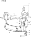
- FIGS. 5A and 5B are side views of the screw driving machine illustrating an operation example of the mechanism that adjusts the force for driving the screw.
- the screw driving machine 1A includes a supply port 34 and a throttle portion 35.
- the supply port 34 connects the air flow path 54 and the driving cylinder 30 on a downstream side of the main valve 5.
- the throttle portion 35 is configured to switch an opening area of the supply port 34.
- the supply port 34 is provided in a side surface of an upper portion of the driving cylinder 30.
- the supply port 34 is formed by an opening that penetrates a side wall of the driving cylinder 30 and connects an outer side and an inner side of the driving cylinder 30.
- the throttle portion 35 includes a cylindrical portion 35a and a plate-like flange portion 35b.
- the cylindrical portion 35a contacts the outer periphery of the driving cylinder 30.
- the plate-like flange portion 35b protrudes from the cylindrical portion 35a toward an outer side direction.
- the throttle portion 35 is vertically movably provided along the outer periphery of the driving cylinder 30 at a portion where the supply port 34 is provided.
- the screw driving machine 1A includes a flow rate switching member 36 that is engageable with the throttle portion 35.
- the flow rate switching member 36 is an example of a flow rate switching portion.
- the flow rate switching member 36 is formed by a plate-like member.
- the flow rate switching member 36 is provided so as to overlap the upper side of the flange portion 35b of the throttle portion 35 on the outer periphery of the driving cylinder 30.
- the flow rate switching member 36 is configured to be rotatable about a shaft of the driving cylinder 30 that is coaxial with the axial direction of the driver bit 2.
- the throttle portion 35 includes a cam surface 37a that converts rotation of the flow rate switching member 36 into movement of the throttle portion 35 in the axial direction of the driving cylinder 30.
- the flow rate switching member 36 includes an engaging portion 37b that follows the cam surface 37a.
- the cam surface 37a is an example of a cam portion.
- the cam surface 37 is formed by a surface inclined in the axial direction of the driving cylinder 30 along a rotation direction of the flow rate switching member 36.
- the engaging portion 37b is an example of the cam portion.
- the engaging portion 37b is configured by a convex portion that protrudes in a direction from the flow rate switching member 36 toward the throttle portion 35 and is in contact with the cam surface 37a.
- the throttle portion 35 is biased by a biasing member 35c such as a coil spring in a direction in which the flange portion 35b approaches the flow rate switching member 36. Accordingly, the throttle portion 35 and the flow rate switching member 36 are engaged with the cam surface 37a via the engaging portion 37b in a form in which the engaging portion 37b is in contact with the cam surface 37a.
- a biasing member 35c such as a coil spring
- the throttle portion 35 does not rotate with respect to the driving cylinder 30, and a portion of the cam surface 37a with which the engaging portion 37b of the flow rate switching member 36 comes into contact changes as the flow rate switching member 36 rotates. Accordingly, the throttle portion 35 moves in a direction approaching and a direction separating from the flow rate switching member 36 according to the rotation direction of the flow rate switching member 36, thereby moving along the axial direction of the driving cylinder 30 interlocking with the rotation of the flow rate switching member 36, and switching a size of the opening area of the supply port 34.
- the screw driving machine 1A includes an operation member 38 configured to cause the flow rate switching member 36 to rotate.
- the operation member 38 includes an operation portion 38a, a shaft portion 38b, and a gear 38c.
- the operation portion 38a receives an operation of causing the flow rate switching member 36 to rotate.
- the shaft portion 38b protrudes from the operation portion 38a.
- the gear 38c is provided on the shaft portion 38b.
- the operation portion 38a is exposed to an outside of the main body portion 10, and the operation portion 38a can be operated from the outside of the main body portion 10.
- the gear 38c rotates about the shaft portion 38b as a fulcrum.
- the gear 38c meshes with a gear 36a provided on an outer periphery of the flow rate switching member 36. Accordingly, in the operation member 38, when the operation portion 38a is operated, the gear 38c rotates about the shaft portion 38b as a fulcrum, and thus the flow rate switching member 36 in which the gear 38c and the gear 36a mesh with each other rotates.
- a material or the like of the driven member 300 is indicated on the operation portion 38a as a guide for selecting a force for driving the screw 200.
- the operation member 38 is configured to operate the operation portion 38a in a direction in which an indication of a desired material can be seen, as illustrated in FIGS. 5A and 5B , according to the material of the driven member 300 that performs driving and tightening of the screw 200, thereby switching the size of the opening area of the supply port 34 in accordance with the material or the like of the driven member 300.
- the start valve 6 includes a pilot valve 61, a valve stem 62, and a valve stem spring 63.
- the pilot valve 61 is configured to open and close the main valve upper chamber 52.
- the valve stem 62 is configured to cause the pilot valve 61 to operate.
- the valve stem spring 63 is configured to bias the pilot valve 61 in the upward direction and to bias the valve stem 62 in the downward direction.
- the pilot valve 61 is pressed in the downward direction due to the air pressure of the compressed air supplied from the main chamber 13. In addition, in the start valve 6, the pilot valve 61 is pressed in the upward direction due to the air pressure of the compressed air supplied from the main chamber 13 to a valve lower chamber 64.
- the pilot valve 61 is held at an upper position based on a relation between a balance of the air pressure of the compressed air and a force of the valve stem spring 63.
- the valve stem 62 moves in the upward direction
- the valve lower chamber 64 is in communication with the atmosphere, and thus the pilot valve 61 moves in the downward direction due to the air pressure of the compressed air.
- the pilot valve 61 moves in the downward direction, a passage through which the main valve upper chamber 52 communicates with the atmosphere is opened.
- the trigger 60 is provided on the lower side of the handle portion 11 and rotates about 60c as a fulcrum in response to an operation of an operator.
- the trigger 60 is biased in the direction separating from the valve stem 62 of the start valve 6 by a trigger spring 60d.
- the trigger 60 includes a contact lever 60a that causes the valve stem 62 of the start valve 6 to operate.
- the contact lever 60a is supported by the trigger 60 so as to be rotatable about a shaft 60b as a fulcrum.
- the contact lever 60a does not come into contact with the valve stem 62 only in a state where an operation of pulling the trigger 60 is performed.
- the contact lever 60a is pressed by an upper arm 81 to be described later of the contact arm 8 in the state where the operation of pulling the trigger 60 is performed, the valve stem 62 is caused to move in the upward direction.
- the contact lever 60a When the operation of pulling the trigger 60 is performed in a state where the contact lever 60a is pressed by the upper arm 81, the contact lever 60a causes the valve stem 62 to move in the upward direction. Accordingly, the start valve 6 is operated by a combination of an operation of the trigger 60 and an operation of being pressed by the contact arm 8. An order of the operation of the trigger 60 and the operation of being pressed by the contact arm 8 is optional.
- the on-off valve 7 is vertically movably supported by an on-off valve cylinder 73 provided in the motor housing 31c.
- an on-off valve lower chamber 73a is provided on the lower side of the on-off valve 7 indicated by the arrow D
- an on-off valve upper chamber 73b is provided on the upper side of the on-off valve 7 indicated by the arrow U.
- the on-off valve 7 is operated by the compressed air supplied from the main chamber 13 and, in a state where the compressed air is not supplied to the on-off valve upper chamber 73b, the on-off valve 7 moves in the upward direction indicated by the arrow U due to the compressed air supplied to the on-off valve lower chamber 73a.
- the on-off valve upper chamber 73b moves in the downward direction as indicated by the arrow D.
- the on-off valve 7 is configured to open and close the air flow path 74 connected to the air motor 31 by moving in the up-down direction.
- the air flow path 74 is an example of a second air flow path.
- the air flow path 74 is in communication with the air flow path 54 on the downstream side of the main valve 5 and on an upstream side of the supply port 34.
- a flow of air between the main chamber 13 and the air motor 31 is blocked when the on-off valve 7 moves in the downward direction and is closed.
- the on-off valve 7 moves in the upward direction and opens, communication between the main chamber 13 and the air motor 31 is established.
- the on-off valve 7 is provided on a side portion of the air motor 31.
- a controller cover 77 covering the on-off valve 7, the controller 70, and the like is fixed to the main body portion 10 by a screw 77a.
- the controller 70 includes a control valve cylinder 75, a first control valve 72, a communication passage 75c, and a second control valve 71.
- the first control valve 72 is accommodated in the control valve cylinder 75 and partitions an inside of the control valve cylinder 75 into a third chamber 75a and a fourth chamber 75b.
- the communication passage 75c allows the inside of the driving cylinder 30 and the third chamber 75a in the control valve cylinder 75 to communicate with each other via the timer chamber 32.
- the second control valve 71 is located on an arrow U direction side with respect to the first control valve 72 and is disposed away from the first control valve 72.
- the controller 70 includes a first biasing member 72b and a second biasing member 71b.
- the first biasing member 72b is a first biasing portion configured to bias the first control valve 72 in an arrow D direction.
- the second biasing member 71a is a second biasing portion configured to bias the second control valve 71 in an arrow D direction.
- the third chamber 75a is provided on the lower side of the first control valve 72 indicated by the arrow D, and the fourth chamber 75b is provided on the upper side of the first control valve 72 indicated by the arrow U.
- the third chamber 75a is in communication with the timer chamber 32 via the communication passage 75c, and is in communication with the space in the driving cylinder 30 via the timer chamber 32.
- the third chamber 75a is in communication with an outside of a body of the screw driving machine 1A via an exhaust passage 75d.
- the first control valve 72 is vertically movably supported by the control valve cylinder 75 along the upward direction indicated by the arrow U and the downward direction indicated by the arrow D.
- a rod-shaped coupling portion 72a extending in the up-down direction is coupled in a form protruding in the upward direction indicated by the arrow U.
- the first control valve 72 is biased in the arrow D direction by the first biasing member 72b such as a coil spring.
- the first control valve 72 is configured to be movable to a standby position P100 which is the bottom dead center position by moving in the downward direction indicated by the arrow D, and is configured to be movable to a later-described operation completion position which is the top dead center position by moving in the upward direction indicated by the arrow U.
- the first control valve 72 moves to the standby position P100 by being biased in the arrow D direction by the first biasing member 72b.
- the first control valve 72 includes a seal portion 72c that opens and closes the exhaust passage 75d.
- the seal portion 72c moves to a position to open the exhaust passage 75d, and the third chamber 75a of the control valve cylinder 75 is in communication with the outside of the body of the screw driving machine 1A via the exhaust passage 75d.
- the seal portion 72c moves to a position to close the exhaust passage 75d.
- the first control valve 72 standing by at the standby position P100 is pressed and operated by a later-described lower arm 80 of the contact arm 8 via a tightening depth adjusting portion 86, and moves from the standby position P100 to the pressure control start position.
- the first control valve 72 moves to the pressure control start position
- the first control valve 72 is operated due to the compressed air supplied from the timer chamber 32 and moves from the pressure control start position to the operation completion position.
- the first control valve 72 presses the second control valve 71 via the coupling portion 72a to cause the second control valve 71 to operate.
- the second control valve 71 is configured by a rod-shaped member extending in the up-down direction, and is vertically movably supported with respect to the on-off valve 7.
- the second control valve 71 moves to a standby position P110 by being biased in the arrow D direction by the second biasing member 71a.
- the second control valve 71 is operated by being pressed by the first control valve 72.
- the second control valve 71 is movable from the standby position P110 to the later-described operation completion position and is configured to cause the on-off valve 7 to operate by switching whether the compressed air is to be supplied to the on-off valve upper chamber 73b of the on-off valve cylinder 73.
- the first control valve 72 and the second control valve 71 are configured by independent members.
- a separation portion 76 is formed separating the first control valve 72 moved to the standby position P100 and the second control valve 71 moved to the standby position P110.
- the separation portion 76 is configured by providing a space between an upper end of the coupling portion 72a, which is an upper end of the first control valve 72, and a lower end of the second control valve 71.
- the tightening depth adjusting portion 86 does not come into contact with the first control valve 72.
- the first control valve 72 is biased by the first biasing member 72b and moves to the standby position P100
- the second control valve 71 is biased by the second biasing member 71a and moves to the standby position P110. Then, the first control valve 72 and the second control valve 71 are separated by the separation portion 76.
- the first control valve 72 when the lower arm 80 moves to the top dead center position, the first control valve 72 is pressed in the upward direction via the tightening depth adjusting portion 86 and moves from the standby position P100 to the pressure control start position. During a period until the first control valve 72 moves from the standby position P100 to the pressure control start position, the second control valve 71 standing by at the standby position P110 and the first control valve 72 moving to the pressure control start position are maintained in a state of being separated from each other by the separation portion 76.
- a configuration is provided such that the upper end of the first control valve 72 and the lower end of the second control valve 71 are not in contact with each other with a movement amount of the first control valve 72 due to movement of the lower arm 80 from the bottom dead center position to the top dead center position.
- the first control valve 72 by moving the first control valve 72 to the pressure control start position, the first control valve 72 is operated due to the compressed air supplied from the timer chamber 32, and when the first control valve 72 moves in the upward direction from the pressure control start position, the first control valve 72 is separated from the tightening depth adjusting portion 86. Further, when the first control valve 72 moves to a second control valve operation start position between the pressure control start position and the operation completion position in the process of moving from the pressure control start position to the operation completion position, the upper end of the first control valve 72 comes into contact with the lower end of the second control valve 71, and the second control valve 71 is pressed in the upward direction by the first control valve 72. In a state where the first control valve 72 has moved to the operation completion position and the second control valve 71 has moved to the operation completion position, the first control valve 72 and the second control valve 71 are not separated from each other.
- the screw feeding portion 9 includes a feeding member 91 and a feed piston 92.
- the feeding member 91 is configured to feed the screw 200.
- the feed piston 92 is configured to cause the feeding member 91 to operate.
- the feeding member 91 is supported so as to be movable in a direction approaching and a direction separating from the nose portion 12.
- the feeding member 91 is configured to feed the screw 200 coupled by the coupling band 201 to the injection passage 12a of the nose portion 12 by locking with a claw portion (not illustrated).
- the feed piston 92 is coupled to the feeding member 91 and is provided in a feed cylinder 93 so as to be slidable.
- the feed cylinder 93 is connected to the blowback chamber 33 via a feed flow path 94, and is supplied with compressed air from the blowback chamber 33.
- the feed piston 92 is operated by an air pressure of the compressed air supplied from the blowback chamber 33 to cause the feeding member 91 to move in the direction separating from the nose portion 12.
- the feed piston 92 causes the feeding member 91 to move in the direction approaching the nose portion 12 by biasing of the biasing member 95.
- the magazine 90 is provided on the lower side of the handle portion 11 and is coupled to the nose portion 12.
- a plurality of screws 200 are coupled by the coupling band 201, and a screw coupling body in a form of, for example, a spiral shape is accommodated.
- the contact arm 8 is an example of a contact portion.
- the contact arm 8 includes the lower arm 80 that comes into contact with the driven member 300 and the upper arm 81 configured to cause a pressing member 87 that presses the contact lever 60a of the trigger 60 to operate.
- the contact arm 8 includes a roller 82 that transmits movement of the lower arm 80 to the upper arm 81.
- the contact arm 8 is configured to be movable in the downward direction indicated by the arrow D, which is the first direction, and the upward direction indicated by the arrow U, which is the second direction opposite to the first direction.
- the contact arm 8 is configured such that the lower arm 80 and the upper arm 81 are interlockingly movable along moving directions of the lower arm 80 indicated by the arrows U and D.
- the contact arm 8 is configured such that the interlocking between the lower arm 80 and the upper arm 81 is released, and the lower arm 80 is movable independently of the upper arm 81.
- the contact arm 8 can move from a first position to a second position via a third position, the first position being the bottom dead center position of the lower arm 80, the second position being the top dead center position of the lower arm 80, and the third position being a sign-in position serving as a starting point of an operation of causing the driver bit 2 to move in the axial direction to drive the screw 200.
- the lower arm 80 is an example of a first arm, is supported by the nose portion 12 of the screw driving machine 1A so as to be movable in the up-down direction, and is biased in the downward direction by a biasing member 83a.
- the biasing member 83a is configured by a coil spring or the like.
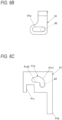
- FIG. 6A is a side view illustrating an example of the lower arm.
- the lower arm 80 includes a cam groove 84.
- the cam groove 84 is configured to switch whether the lower arm 80 and the upper arm 81 are to be interlocked with each other and to switch relative positions of the lower arm 80 and the upper arm 81 along the moving direction of the lower arm 80.
- the lower arm 80 includes a bottom dead center position switching affected portion 85.
- the bottom dead center position switching affected portion 85 receives a force that causes the lower arm 80 to move in the upward direction by relative movement with respect to the main body portion 10 when the relative positions of the lower arm 80 and the upper arm 81 are switched.
- the cam groove 84 includes a first engaging portion 84a and a first engagement releasing portion 84b.
- the first engaging portion 84a interlockingly engages the lower arm 80 and the upper arm 81 via the roller 82.
- the first engagement releasing portion 84b releases the interlocking engagement between the lower arm 80 and the upper arm 81 by the first engaging portion 84a via the roller 82, thereby allowing the lower arm 80 to move independently with respect to the upper arm 81.
- the cam groove 84 includes a second engaging portion 84c and a second engagement releasing portion 84d.
- the second engaging portion 84c interlockingly engages the lower arm 80 and the upper arm 81 via the roller 82.
- the second engagement releasing portion 84d releases the interlocking engagement between the lower arm 80 and the upper arm 81 by the second engaging portion 84c via the roller 82, thereby allowing the lower arm 80 to move independently with respect to the upper arm 81.
- the first engaging portion 84a is a portion above the cam groove 84 extending in the up-down direction.
- the first engaging portion 84a is provided on a surface located on the lower side among surfaces of the cam groove 84 facing each other in the up-down direction.
- the first engaging portion 84a intersects the moving directions of the lower arm 80 indicated by the arrows U and D, and is formed by a surface capable of pressing the roller 82 in the upward direction indicated by the arrow U by an operation of moving the lower arm 80 in the arrow U direction.
- the first engagement releasing portion 84b is configured by a surface that extends from the first engaging portion 84a in an oblique downward direction and guides the roller 82 in a lateral direction intersecting the movement direction of the lower arm 80.
- the second engaging portion 84c is a portion connected to a lower end of the first engagement releasing portion 84b in the cam groove 84.
- the second engaging portion 84c is provided on a surface located on the lower side among the surfaces of the cam groove 84 facing each other in the up-down direction.
- the second engaging portion 84c is configured by a surface that intersects the moving directions of the lower arm 80 indicated by the arrows U and D and presses the roller 82 in the upward direction indicated by the arrow U by the operation of moving the lower arm 80 in the arrow U direction.
- the second engagement releasing portion 84d is configured by a surface that extends from the second engaging portion 84c in an oblique downward direction and guides the roller 82 in the lateral direction intersecting the movement direction of the lower arm 80.
- the first engaging portion 84a, the first engagement releasing portion 84b, the second engaging portion 84c, and the second engagement releasing portion 84d are surfaces connected in a substantially crank shape, and when a position with which the roller 82 comes into contact is changed, the interlocking engagement between the lower arm 80 and the upper arm 81 via the roller 82 and releasing of the interlocking engagement between the lower arm 80 and the upper arm 81 are switched.
- the upper arm 81 is an example of a second arm.
- the upper arm 81 is supported by a side portion of the main body portion 10 of the screw driving machine 1A so as to be movable in the up-down direction, and is biased in the downward direction by a biasing member 83b configured by a coil spring or the like.
- FIG. 6B is a side view illustrating an example of the upper arm.
- the upper arm 81 has a guide groove 81a to which movement of the lower arm 80 is transmitted via the roller 82.
- a length of the guide groove 81a in a short direction is slightly longer than a diameter of the roller 82, and a longitudinal direction of the guide groove 81a extends in a direction intersecting the moving direction of the upper arm 81 and the moving direction of the lower arm 80 illustrated in FIG. 6B and the like.
- the roller 82 is an example of a transmission member.
- the roller 82 is inserted into the cam groove 84 of the lower arm 80 and the guide groove 81a of the upper arm 81.
- the roller 82 is formed to have a cylindrical shape rotatable along the cam groove 84 and the guide groove 81a.
- the roller 82 is biased by a biasing member 82a such as a torsion coil spring in a direction in which the roller 82 is pressed against the first engaging portion 84a, the first engagement releasing portion 84b, the second engaging portion 84c, and the second engagement releasing portion 84d.
- the first engaging portion 84a is a surface in the direction intersecting the moving direction of the lower arm 80. Therefore, when the lower arm 80 moves in the upward direction due to the relative movement with respect to the main body portion 10 in a state where the roller 82 is located at a position facing the first engaging portion 84a, the cam groove 84 provided in the lower arm 80 moves in the upward direction, and the first engaging portion 84a comes into contact with the roller 82 from the lower side and presses the roller 82 in the upward direction. In addition, the roller 82 pressed in the upward direction by the first engaging portion 84a of the cam groove 84 presses a surface on the upper side of the guide groove 81a in the upward direction.
- the movement of the lower arm 80 is in a state of being able to be transmitted to the upper arm 81 via the first engaging portion 84a and the roller 82, and the first engaging portion 84a interlockingly engages the lower arm 80 and the upper arm 81 via the roller 82.
- the first engagement releasing portion 84b extends from the first engaging portion 84a in the oblique downward direction. Therefore, when the lower arm 80 moves in the upward direction due to the relative movement with respect to the main body portion 10 in a state where the roller 82 is at a position facing the first engagement releasing portion 84b, a force is generated for the first engagement releasing portion 84b to press the roller 82 in the lateral direction. Thus, the first engagement releasing portion 84b guides the roller 82 along the guide groove 81a of the upper arm 81 in the direction intersecting the moving direction of the lower arm 80.
- the movement of the lower arm 80 is in a non-transmission state of not being transmitted to the upper arm 81 via the first engagement releasing portion 84b and the roller 82, and the first engagement releasing portion 84b releases the interlocking engagement between the lower arm 80 and the upper arm 81 via the roller 82.
- the second engaging portion 84c is a surface in the direction intersecting the moving direction of the lower arm 80. Therefore, when the lower arm 80 moves in the upward direction due to the relative movement with respect to the main body portion 10 in a state where the roller 82 is located at a position facing the second engaging portion 84c, the cam groove 84 provided in the lower arm 80 moves in the upward direction, and the second engaging portion 84c comes into contact with the roller 82 from the lower side and presses the roller 82 in the upward direction. In addition, the roller 82 pressed in the upward direction by the second engaging portion 84c of the cam groove 84 presses the surface on the upper side of the guide groove 81a in the upward direction.
- the movement of the lower arm 80 is in a state of being able to be transmitted to the upper arm 81 via the second engaging portion 84c and the roller 82, and the second engaging portion 84c interlockingly engages the lower arm 80 and the upper arm 81 via the roller 82.
- the second engagement releasing portion 84d extends from the second engaging portion 84c in the oblique downward direction. Therefore, when the lower arm 80 moves in the upward direction due to the relative movement with respect to the main body portion 10 in a state where the roller 82 is at a position facing the second engagement releasing portion 84d, a force is generated for the second engagement releasing portion 84d to press the roller 82 in the lateral direction. Thus, the second engagement releasing portion 84d guides the roller 82 along the guide groove 81a of the upper arm 81 in the direction intersecting the moving direction of the lower arm 80.
- the movement of the lower arm 80 is in a non-transmission state of not being transmitted to the upper arm 81 via the second engagement releasing portion 84d and the roller 82, and the second engagement releasing portion 84d releases the interlocking engagement between the lower arm 80 and the upper arm 81 via the roller 82.
- the lower arm 80 moves in the upward direction due to the relative movement with respect to the main body portion 10 by an operation of pressing the contact arm 8 against the driven member 300.
- the upper arm 81 is interlockingly engaged with the lower arm 80 via the roller 82
- the surface on the upper side of the guide groove 81a is pressed by the roller 82, so that the upper arm 81 moves in the upward direction interlockingly with the lower arm 80.
- the upper arm 81 moved in the upward direction interlockingly with the lower arm 80 is biased in the downward direction by the biasing member 83b, so that the surface on the upper side of the guide groove 81a comes into contact with the roller 82 and presses the roller 82 in the downward direction.
- the upper arm 81 is regulated from moving downward independently of the lower arm 80.
- the lower arm 80 moves in the upward direction from the bottom dead center position due to the relative movement with respect to the main body portion 10 by the operation of pressing the contact arm 8 against the driven member 300, and at the same time, the upper arm 81 moves in the upward direction interlockingly with the lower arm 80 within a predetermined range in which the lower arm 80 moves in the upward direction from the bottom dead center position.
- the main body portion 10 and the driven member 300 relatively approach each other.
- the driving depth regulating portion 4a regulates, between the sign-in position and the top dead center position, the movement amount of the lower arm 80 from the bottom dead center position.
- the sign-in position is a third position and is between the top dead center position and a position to which the lower arm 80 moved in the upward direction by a predetermined amount from the bottom dead center position.
- sign-in is possible.
- the driving depth switching portion 4b to operate switching of whether to regulate the movement amount of the lower arm 80 from the bottom dead center position by the driving depth regulating portion 4a, the driving depth of the screw 200 with respect to the driven member 300 is switched.
- the screw driving machine 1A by enabling the bottom dead center position of the lower arm 80 to be switched, the movement amount of the contact arm 8 is reduced when the driving depth of the screw 200 is increased.
- the driving depth regulating portion 4a includes a locking member 40 that regulates a movement amount of the lower arm 80 from a first bottom dead center position P1 illustrated in FIG. 2A .
- the driving depth switching portion 4b includes a switching member 41 configured to switch whether the movement amount of the lower arm 80 is to be regulated by the locking member 40.
- the switching member 41 also has a function of guiding a movement path of the roller 82 which moves together with the lower arm 80 and the upper arm 81, and switching whether the lower arm 80 and the upper arm 81 are to be interlocked with each other.
- the driving depth switching portion 4b includes a switching operation member 42 configured to cause the switching member 41 to operate and to switch the bottom dead center position of the lower arm 80 to the first bottom dead center position P1 illustrated in FIG. 2A or a second bottom dead center position P2 illustrated in FIG. 2B .
- the locking member 40 is rotatably supported by the feeding member 91 of the screw 200 with a shaft 40a as a fulcrum.
- a locking portion 40b to be locked to the lower arm 80 is formed on one of end portions with the shaft 40a interposed therebetween.
- an affected portion 40c that receives a force for causing the locking member 40 to rotate by the switching member 41 is formed on the other of the end portions with the shaft 40a interposed therebetween.
- the locking member 40 is biased by a biasing member 40d configured by a coil spring or the like in a direction in which the locking portion 40b protrudes to the movement path of the lower arm 80 by a rotating operation with the shaft 40a as a fulcrum.
- the locking member 40 moves, due to the movement of the feeding member 91, between a locking position illustrated in FIG. 3A and the like at which the locking portion 40b protrudes to the movement path of the lower arm 80 and a second retracted position to which the locking portion 40b is retracted from the movement path of the lower arm 80.
- the locking member 40 moves between the locking position and a first retracted position illustrated in FIG. 3B and the like to which the locking portion 40b is retracted from the movement path of the lower arm 80 by the rotating operation with the shaft 40a as a fulcrum.
- the switching member 41 is supported on a side portion of the nose portion 12 of the screw driving machine 1A so as to be movable in an arrow L direction or an arrow R direction intersecting with the up-down direction.
- FIG. 6C is a side view illustrating an example of the switching member.
- the switching member 41 has a guide groove 41a that guides and causes the roller 82 to move to a predetermined position.
- the switching member 41 includes an actuation portion 41b that causes the locking member 40 to operate.
- the switching member 41 includes an affected portion 41c that receives a force for causing the switching member 41 to move in the arrow L direction or the arrow R direction intersecting the up-down direction.
- the guide groove 41a has a first guide groove 41a1.
- the first guide groove 41a1 guides the roller 82 engaged with the first engaging portion 84a of the cam groove 84 from the first engaging portion 84a to the first engagement releasing portion 84b and guides the roller 82 engaged with the second engaging portion 84c of the cam groove 84 from the second engaging portion 84c to the second engagement releasing portion 84d.
- the first guide groove 41a1 extends in an oblique upward direction.
- the first guide groove 41a1 causes the roller 82, which moves in the arrow U direction following the lower arm 80, to move in the arrow L direction from the first engaging portion 84a toward the first engagement releasing portion 84b by an operation of moving the lower arm 80 in the upward direction due to the relative movement with respect to the main body portion 10.
- the first guide groove 41a1 guides the roller 82 from the second engaging portion 84c to the second engagement releasing portion 84d.
- the guide groove 41a has a second guide groove 41a2 that regulates movement of the roller 82 in the downward direction.
- the second guide groove 41a2 is a portion extending from the first guide groove 41a1 in the lateral direction intersecting the up-down direction, and is configured by a surface located on the lower side among surfaces facing each other in the up-down direction.
- the switching operation member 42 is an example of a switching operation portion.
- the switching operation member 42 includes, as illustrated in FIGS. 2A , 2B , 3A, 3B , and the like, an action portion 42a that causes the lower arm 80 to move interlockingly with the switching member 41, and an operation portion 42b that receives an operation of a person.
- the action portion 42a includes a first cam surface 42a1.
- the first cam surface 42a1 is in contact with the bottom dead center position switching affected portion 85 of the lower arm 80 and causes the lower arm 80 to move in the upward direction.
- the action portion 42a includes a second cam surface 42a2.
- the second cam surface 42a2 is in contact with the affected portion 41c of the switching member 41 and causes the switching member 41 to move in the direction indicated by the arrow L or the arrow R.
- the first cam surface 42a1 and the second cam surface 42a2 are displaced by a rotating operation with a shaft 42c as a fulcrum.
- the operation portion 42b is coupled to the shaft 42c and causes the action portion 42a to rotate with the shaft 42c as a fulcrum.
- the switching operation member 42 causes the switching member 41 to move in the direction indicated by the arrow L or the arrow R.
- the lower arm 80 is caused to move in the up-down direction.
- the roller 82 is guided by the guide groove 41a of the switching member 41 by the operation of moving the lower arm 80 in the up-down direction, and thus the roller 82 engaged with the first engaging portion 84a of the cam groove 84 is guided from the first engaging portion 84a to the first engagement releasing portion 84b.
- the roller 82 is guided from the second engaging portion 84c to the second engagement releasing portion 84d. Accordingly, the lower arm 80 moves in the up-down direction independently of the upper arm 81 by the operation of the operation portion 42b.
- the screw driving machine 1A includes the tightening depth adjusting portion 86 configured to adjust a tightening depth of the screw 200 by defining an upper fulcrum position of the lower arm 80 and causes the first control valve 72 to operate when the lower arm 80 moves to the upper fulcrum position.
- the tightening depth adjusting portion 86 is an example of a tightening depth switching portion.
- the tightening depth adjusting portion 86 includes an adjusting portion main body 86a and an abutting portion 86b whose protrusion height with respect to the adjusting portion main body 86a is adjustable.
- the tightening depth adjusting portion 86 is supported so as to be movable along the moving direction of the lower arm 80 indicated by the arrows U and D, and is biased in the downward direction indicated by the arrow U by a biasing member 86c such as a coil spring.
- the tightening depth adjusting portion 86 has a configuration in which the adjusting portion main body 86a and an abutting portion 86b are joined by, for example, screwing a male screw and a female screw.
- a dial portion 86d for causing the adjusting portion main body 86a to rotate is exposed to the outside of the main body portion 10.
- the adjusting portion main body 86a is caused to rotate by an operation of the dial portion 86d, whereby a protrusion amount of the abutting portion 86b with respect to the adjusting portion main body 86a is switched, and an entire length of the tightening depth adjusting portion 86 is changed.
- the abutting portion 86b faces the lower arm 80.
- the abutting portion 86b and the lower arm 80 are separated from each other.
- the tightening depth adjusting portion 86 when the lower arm 80 moves in the upward direction from the bottom dead center position, the lower arm 80 comes into contact with the abutting portion 86b.
- the adjusting portion main body 86a faces the first control valve 72.
- the adjusting portion main body 86a and the first control valve 72 are separated from each other.
- the tightening depth adjusting portion 86 when the lower arm 80 moves in the upward direction from the bottom dead center position as indicated by the arrow U, the lower arm 80 comes into contact with the abutting portion 86b, and when the tightening depth adjusting portion 86 is pressed by the lower arm 80 and moved in the upward direction, the adjusting portion main body 86a comes into contact with the first control valve 72.
- the tightening depth adjusting portion 86 When the tightening depth adjusting portion 86 is pressed up by the lower arm 80 moving in the arrow U direction and moves to a position where the adjusting portion main body 86a comes into contact with a movement regulating portion 86e, the tightening depth adjusting portion 86 regulates the lower arm 80 from further moving in the upward direction.
- the position of the lower arm 80 regulated by the movement of the tightening depth adjusting portion 86 to the position in contact with the movement regulating portion 86e becomes the upper fulcrum position of the lower arm 80.
- the protrusion amount of the abutting portion 86b with respect to the adjusting portion main body 86a is switched by the operation of the dial portion 86d, and the entire length of the tightening depth adjusting portion 86 is changed.
- the entire length of the tightening depth adjusting portion 86 changes, the top dead center position of the lower arm 80 moves.
- a protrusion amount of the driver bit 2 with respect to a lower end surface of the lower arm 80 changes, the driver bit 2 being moved to the bottom dead center position with respect to the lower end surface of the lower arm 80, and the tightening depth of the screw 200 with respect to the driven member 300 changes.
- the tightening depth adjusting portion 86 may not be provided, the lower arm 80 may directly contact the first control valve 72 to cause the first control valve 72 to operate, and the upper fulcrum position of the lower arm 80 may be defined.
- the screw driving machine 1A is switched between a first mode and a second mode.
- the driving depth of the screw 200 is set to a first driving depth.
- the driving depth of the screw 200 is set to be deeper than the first driving depth.
- the switching between the first mode and the second mode is performed at a timing when driving and tightening operations of the screw 200 are not performed, such as after the driving and tightening operations of the screw 200 are finished and before next driving and tightening operations of the screw 200 are started.
- the bottom dead center position of the lower arm 80 is set to the first bottom dead center position P1 illustrated in FIG. 2A , and in a state where the movement amount of the lower arm 80 from the first bottom dead center position P1 is regulated, after the screw 200 is driven into the driven member 300, the regulation of the movement amount of the lower arm 80 is released, and the screw 200 is tightened.
- the bottom dead center position of the lower arm 80 is lowered to the first bottom dead center position P1.
- the locking member 40 moves to the locking position where the locking portion 40b of the locking member 40 protrudes to the movement path of the lower arm 80.
- the action portion 42a rotates counterclockwise as indicated by an arrow C1 by the operation of the operation portion 42b.
- the first cam surface 42a1 is separated from the bottom dead center position switching affected portion 85 of the lower arm 80. Accordingly, the lower arm 80 is biased in the downward direction by the biasing member 83a and stands by in a state of being moved to the first bottom dead center position P1 as illustrated in FIG. 2A .
- the roller 82 In a state where the lower arm 80 stands by at the first bottom dead center position P1 and the switching member 41 moves in the arrow R direction, the roller 82 is guided to a predetermined position by the first guide groove 41a1 of the guide groove 41a of the switching member 41. Accordingly, the roller 82 is engaged with the first engaging portion 84a of the cam groove 84.
- the locking member 40 In a state where the switching member 41 moves in the arrow R direction, the actuation portion 41b moves in a direction separating from the affected portion 40c of the locking member 40. Accordingly, the locking member 40 is biased by the biasing member 40d in the direction in which the locking portion 40b protrudes to the movement path of the lower arm 80 by the rotating operation with the shaft 40a as a fulcrum, and thus, as illustrated in FIG. 3A , the locking member 40 moves to the locking position at which the locking portion 40b protrudes to the movement path of the lower arm 80.
- the bottom dead center position of the lower arm 80 is set to the second bottom dead center position P2 illustrated in FIG. 2B , and in a state where the regulation of the movement amount of the lower arm 80 from the second bottom dead center position P2 is released, the screw 200 is driven into the driven member 300, and then the screw 200 is tightened.
- the bottom dead center position of the lower arm 80 is raised to the second bottom dead center position P2, and the locking portion 40b of the locking member 40 is caused to move to the retracted position to which the locking portion 40b is retracted from the movement path of the lower arm 80.
- the action portion 42a is caused to rotate clockwise as indicated by an arrow C2 by the operation of the operation portion 42b.
- the action portion 42a rotates clockwise as indicated by the arrow C2
- the first cam surface 42a1 comes into contact with the bottom dead center position switching affected portion 85 of the lower arm 80 and presses up the bottom dead center position switching affected portion 85. Accordingly, the lower arm 80 moves in the upward direction and moves to the second bottom dead center position P2 as illustrated in FIG. 2B .
- the roller 82 When the lower arm 80 moves from the first bottom dead center position P1 to the second bottom dead center position P2 and the switching member 41 moves in the arrow L direction, the roller 82 is guided by the guide groove 41a of the switching member 41. Accordingly, the roller 82 is guided from the first engaging portion 84a to the first engagement releasing portion 84b of the cam groove 84, guided from the first engagement releasing portion 84b to the second engaging portion 84c, and engages with the second engaging portion 84c.
- the switching member 41 moves in the arrow L direction
- the actuation portion 41b presses the affected portion 40c of the locking member 40. Accordingly, by the rotating operation with the shaft 40a as a fulcrum, the locking member 40 moves to the first retracted position to which the locking portion 40b is retracted from the movement path of the lower arm 80, as illustrated in FIG. 3B .
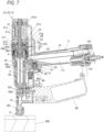
- FIG. 7 is a side sectional view of the screw driving machine illustrating an example of an operation of driving a screw into a driven member and tightening the screw
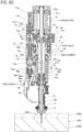
- FIGS. 8A , 8B , 8C , 8D , 8E , 8F , and 8G are front sectional views of the screw driving machine illustrating an example of an operation of driving the screw into the driven member and tightening the screw
- FIGS. 9A and 9B are side sectional views of main parts of the screw driving machine according to the present illustrative embodiment illustrating an example of an operation of driving the screw into the driven member and tightening the screw in the first mode
- FIGS. 10A and 10B are bottom sectional views of the main parts of the screw driving machine according to the present illustrative embodiment illustrating an example of the operation of driving the screw into the driven member and tightening the screw in the first mode.
- the lower arm 80 moves to the first bottom dead center position P1.
- the locking member 40 moves to the locking position where the locking portion 40b protrudes to the movement path of the lower arm 80.
- the first bottom dead center position P1 of the lower arm 80 is also referred to as the first position.
- the operator holds the handle portion 11 of the screw driving machine 1A and presses the contact arm 8 against the driven member 300.
- the screw driving machine 1A when the contact arm 8 is pressed against the driven member 300, the lower arm 80 moves in the upward direction due to the relative movement with respect to the main body portion 10.
- the first driving depth defining position P10 of the lower arm 80 is the same as the third position, but the first driving depth defining position P10 and the third position may be different positions.
- the third position may be set at the same position as the first driving depth defining position P10, or above the bottom dead center position of the lower arm 80 and below the first driving depth defining position P10.
- the upper arm 81 moves to the operation possible position where the contact lever 60a of the trigger 60 is caused to operate. Accordingly, in a state where the contact arm 8 is pressed against the driven member 300 until the lower arm 80 moves to the first driving depth defining position P10, when the operation of pulling the trigger 60 is performed, as illustrated in FIGS. 7A and 9A , the contact lever 60a presses the valve stem 62 of the start valve 6, and the start valve 6 is operated. In this manner, a state where the valve stem 62 is pressed by the contact lever 60a by operating the trigger 60 in the state where the contact arm 8 is pressed against the driven member 300 until the lower arm 80 moves to the first driving depth defining position P10 is referred to as sign-in in the first mode.
- the main valve 5 When the start valve 6 is operated in the state of sign-in in the first mode, the main valve 5 is operated as illustrated in FIG. 8B , and the compressed air is supplied to the driving cylinder 30 and the on-off valve 7.
- the driving piston 30a to which the driver bit 2 is attached is pressed by the air pressure, and as illustrated in FIG. 8C , the driver bit 2 (driving piston 30a) moves in the downward direction from the top dead center position to the bottom dead center position, and the screw 200 is driven into the driven member 300.
- the locking member 40 attached to the feeding member 91 moves in the arrow L direction. Accordingly, the locking member 40 moves to the second retracted position to which the locking portion 40b is retracted from the movement path of the lower arm 80.
- the locking member 40 moves to the second retracted position, by the operation of pressing the contact arm 8 against the driven member 300, the lower arm 80 can move in the upward direction beyond the first driving depth defining position P10 due to the relative movement with respect to the main body portion 10.
- the driver bit 2 rotates, and as illustrated in FIG. 8D , the screw 200 driven into the driven member 300 is tightened.
- the main body portion 10 further moves in the downward direction following the tightening of the screw 200.
- the roller 82 guided from the first engaging portion 84a to the first engagement releasing portion 84b of the cam groove 84 is guided from the first guide groove 41a1 to the second guide groove 41a2 of the guide groove 41a. Accordingly, while the upper arm 81 moves to the operation possible position and the roller 82 is located in the second guide groove 41a2, the position of the upper arm 81 is maintained at the operation possible position.
- the main body portion 10 By the operation of pressing the contact arm 8 against the driven member 300, the main body portion 10 further moves in the downward direction following the tightening of the screw 200, and the lower arm 80 moves relatively in the upward direction.
- the lower arm 80 comes into contact with the tightening depth adjusting portion 86 and presses the tightening depth adjusting portion 86 in the upward direction.
- the tightening depth adjusting portion 86 is pressed up by the lower arm 80 moving in the upward direction and the tightening depth adjusting portion 86 moves to a position where the tightening depth adjusting portion 86 comes into contact with the movement regulating portion 86e, the lower arm 80 is regulated from further moving in the upward direction.
- the position of the lower arm 80 regulated by the movement of the tightening depth adjusting portion 86 to the position in contact with the movement regulating portion 86e becomes the upper fulcrum position of the lower arm 80.
- the lower arm 80 presses the first control valve 72 in the upward direction via the tightening depth adjusting portion 86, and the first control valve 72 moves from the standby position P100 illustrated in FIG. 8A and the like to a pressure control start position P101.
- the pressure control start position P101 is also referred to as a second position of the first control valve 72.
- the tightening depth adjusting portion 86 comes into contact with the first control valve 72, and the first control valve 72 moves from the standby position P100 to the pressure control start position P101, the second control valve 71 standing by at the standby position P110 illustrated in FIG. 8D and the like and the first control valve 72 are separated from each other by the separation portion 76.
- the second control valve 71 standing by at the standby position P110 and the first control valve 72 are separated by the separation portion 76.
- the third chamber 75a is normally in communication with the space in the driving cylinder 30 via the communication passage 75c and the side hole flow path 32a of the driving cylinder 30.
- the driving piston 30a moves in the downward direction by a predetermined distance, and the seal portion 30b passes through the side hole flow path 32a, the second chamber 30d in the driving cylinder 30, which is the upper chamber of the driving cylinder, and the third chamber 75a of the control valve cylinder 75 are in communication with each other.
- the compressed air is supplied from the second chamber 30d to the timer chamber 32.
- the seal portion 72c of the first control valve 72 is at a position where the exhaust passage 75d is opened, and the third chamber 75a of the control valve cylinder 75 is in communication with the outside of the body of the screw driving machine 1A via the exhaust passage 75d. Accordingly, even when the compressed air is supplied from the timer chamber 32 to the third chamber 75a of the control valve cylinder 75, the third chamber 75a is maintained at atmospheric pressure, and the first control valve 72 does not operate with the air pressure.
- the seal portion 72c of the first control valve 72 closes the exhaust passage 75d.
- pressure in the control valve cylinder 75 increases due to the air pressure of the compressed air supplied from the timer chamber 32 to the third chamber 75a of the control valve cylinder 75.
- the first control valve 72 is operated due to the air pressure, and as illustrated in FIG. 8F , the first control valve 72 further moves in the upward direction.
- the first control valve 72 When the first control valve 72 further moves in the upward direction from the pressure control start position P101 due to the air pressure of the compressed air and the first control valve 72 moves to the second control valve operation start position, the first control valve 72 comes into contact with the second control valve 71, and the first control valve 72 presses the second control valve 71 in the upward direction.
- the second control valve 71 moves to an operation completion position P111 by movement of the first control valve 72 to an operation completion position P102, the compressed air is supplied to the on-off valve upper chamber 73b of the on-off valve cylinder 73 which is a space on the upper side of the on-off valve 7.
- the lower arm 80 moves in the arrow D direction by the biasing of the biasing member 83a due to the relative movement of the main body portion 10 and the lower arm 80.
- the roller 82 moves in the arrow R direction by a biasing force of the biasing member 82a, so that the roller 82 comes out of the second guide groove 41a2 and becomes movable in the downward direction, and the upper arm 81 follows the lower arm 80 due to the biasing of the biasing member 83b and moves in the arrow D direction due to the relative movement with respect to the main body portion 10, and the roller 82 entering the guide groove 81a moves in the arrow D direction.
- a feeding pawl (not illustrated) provided on the feeding member 91 feeds a next screw 200 to the nose portion 12.
- the locking member 40 attached to the feeding member 91 moves in the arrow R direction. Accordingly, the locking member 40 moves to the locking position where the locking portion 40b protrudes to the movement path of the lower arm 80.
- FIGS. 11A and 11B are side sectional views of main parts of the screw driving machine according to the present illustrative embodiment illustrating the example of the operation of driving the screw into the driven member and tightening the screw in the second mode
- FIGS. 12A and 12B are bottom sectional views of the main parts of the screw driving machine according to the present illustrative embodiment illustrating the example of the operation of driving the screw into the driven member and tightening the screw in the second mode.
- the lower arm 80 moves to the second bottom dead center position P2.
- the locking member 40 moves to the first retracted position to which the locking portion 40b is retracted from the movement path of the lower arm 80.
- the second bottom dead center position P2 of the lower arm 80 is also referred to as the first position.
- the operator holds the handle portion 11 of the screw driving machine 1A and presses the contact arm 8 against the driven member 300.
- the screw driving machine 1A when the contact arm 8 is pressed against the driven member 300, the lower arm 80 moves in the upward direction due to the relative movement with respect to the main body portion 10.
- the upper arm 81 moves to the operation possible position where the contact lever 60a of the trigger 60 is caused to operate.
- the second driving depth defining position P20 of the lower arm 80 is the top dead center position. Accordingly, in a state where the contact arm 8 is pressed against the driven member 300 until the lower arm 80 moves to the second driving depth defining position P20, when the operation of pulling the trigger 60 is performed, the contact lever 60a presses the valve stem 62 of the start valve 6, and the start valve 6 is operated.
- the main valve 5 When the start valve 6 is operated in the state of sign-in in the second mode, the main valve 5 is operated as illustrated in FIG. 8B , and the compressed air is supplied to the driving cylinder 30.
- the driving piston 30a to which the driver bit 2 is attached is pressed by the air pressure, and as illustrated in FIG. 8C , the driver bit 2 (driving piston 30a) moves in the downward direction from the top dead center position to the bottom dead center position, and the screw 200 is driven into the driven member 300.
- the locking member 40 attached to the feeding member 91 moves in the arrow L direction. Accordingly, even when the locking member 40 moves from the first retracted position, the locking portion 40b maintains a state of being retracted from the movement path of the lower arm 80.
- the locking member 40 moves to the first retracted position, and the locking portion 40b is maintained in the state of being retracted from the movement path of the lower arm 80.
- a length from the lower end (tip) of the driver bit 2 to the lower end (tip) of the contact arm 8 that is, a length from the lower end (tip) of the driver bit 2 to the driven member 300 can be made shorter than the same length in the first mode.
- a movement amount of the driver bit 2 is the same in the first mode and the second mode.
- the screw driving machine 1A can make the second driving depth deeper than the first driving depth, the second driving depth being the driving depth of the screw 200 in the second mode, and the first driving depth being the driving depth of the screw 200 in the first mode.
- the tip of the screw 200 needs to penetrate an upper material 300a of the driven member 300 and be driven halfway into a lower material 300b.
- the screw 200 is excessively driven, a hole larger than a screw diameter is deeply bored in the lower material 300b, and thus there is a possibility that an engagement amount of the screw 200 is short and a fastening force is weakened.
- the screw 200 cannot be driven into the lower material 300b, there is a possibility that the screw 200 cannot be tightened into the lower material 300b and the construction fails.
- the first mode is selected in a case where the screw 200 is driven and tightened into the driven member 300 in which the screw 200 is likely to be excessively driven.
- the driving depth of the screw 200 is made relatively shallow, and a hole larger than the screw diameter can be prevented from being deeply bored in the lower material 300b, and a decrease in the fastening force can be prevented.
- the second mode is selected in a case where the screw 200 is driven and tightened into the driven member 300 in which the screw 200 is less likely to be excessively driven.
- the driving depth of the screw 200 is made relatively deep, the screw 200 can be reliably driven into the lower material 300b, and the tightening of the screw 200 can be reliably performed.
- the driving depth of the screw 200 can be selected according to a material, a thickness, and the like of the driven member 300.
- a time required for an operation of moving the contact arm 8 (lower arm 80) from the second bottom dead center position P2 to the top dead center position and an operation of returning the contact arm 8 from the top dead center position to the second bottom dead center position P2 can be shortened, and a time required for an operation of continuously driving and tightening the screw 200 can be shortened.
- the operation of causing the bottom dead center position of the contact arm 8 (lower arm 80) to move to the second bottom dead center position P2 and the operation of causing the locking member 40 to move to the retracted position can be performed interlockingly with each other by the switching operation member 42 that causes the switching member 41 to move. Accordingly, the switching between the first mode and the second mode can be easily performed by operating the operation portion 42b of the switching operation member 42.
- a force for driving the screw 200 into the driven member 300 is switched by switching the size of the opening area of the supply port 34 in accordance with the switching between the first mode and the second mode. That is, in the case where the screw 200 is driven and tightened into the driven member 300 in which the screw 200 is likely to be excessively driven, the first mode is selected as described above. In a case where the first mode is selected, a base material of the driven member 300 is a steel plate having a small thickness. Therefore, the screw 200 is likely to be excessively driven, and since the base material is hard, it is necessary to increase the force for driving the screw 200 into the driven member 300 as compared to wood or the like.
- the operation portion 38a of the flow rate switching member 36 is operated in a direction in which an indication (iron or the like) of a desired material can be seen. Accordingly, as illustrated in FIG. 4A , the throttle portion 35 moves in a direction approaching the flow rate switching member 36 according to the rotation direction of the flow rate switching member 36, thereby moving along the axial direction of the driving cylinder 30 interlocking with the rotation of the flow rate switching member 36, and widening the opening area of the supply port 34. Accordingly, a flow rate of the compressed air supplied to the driving cylinder 30 can be increased, and the force for driving the screw 200 into the driven member 300 can be increased.
- the base material of the driven member 300 is often wood having a large thickness. Therefore, the excessive driving of the screw 200 is less likely to occur, and it is necessary to reduce the force for driving the screw 200 into the driven member 300 as compared to a base material such as a steel plate.
- the operation portion 38a of the flow rate switching member 36 is operated in a direction in which an indication (wood or the like) of a desired material can be seen. Accordingly, as illustrated in FIG. 4B , the throttle portion 35 moves in a direction separating from the flow rate switching member 36 according to the rotation direction of the flow rate switching member 36, thereby moving along the axial direction of the driving cylinder 30 interlocking with the rotation of the flow rate switching member 36, and narrowing the opening area of the supply port 34.
- a flow rate of the compressed air supplied to the driving cylinder 30 can be reduced, and the force for driving the screw 200 into the driven member 300 can be reduced.
- the air flow path 74 connecting the main chamber 13 and the air motor 31 is connected to the air flow path 54 on the downstream side of the main valve 5 and on the upstream side of the supply port 34. Accordingly, the compressed air supplied to the air motor 31 does not pass through the supply port 34 and is not affected by the throttle portion 35. Therefore, the flow rate of the compressed air flowing to the air motor 31 is not reduced, and a speed of tightening due to the rotation of the driver bit 2 does not decrease. In other words, the flow rate of the compressed air supplied to the air motor 31 via the air flow path 74 can be made constant, while the flow rate of the compressed air supplied to the driving cylinder 30 via the air flow path 54 is adjustable by adjusting the size of the opening area of the supply port 34 by the flow rate switching member 34.
- the screw coupling body is accommodated in the magazine 90, so that in a case where the screw driving machine 1A is used in a lateral orientation, a weight of the screw coupling body is applied to the front side of the handle portion 11. In contrast, in the case where the screw driving machine 1A is used in a lateral orientation, a weight of the air motor 31 is applied to the rear side of the handle portion 11. Accordingly, the screw driving machine 1A has a configuration in which heavy members are provided on both the front and rear sides with the handle portion 11 interposed therebetween.
- the throttle portion 35 for switching the opening area of the supply port 34 is provided on the outer periphery of the driving cylinder 30, a space for providing the throttle portion 35 and the flow rate switching member 36 and a space for the throttle portion 35 to operate are not required between the driving cylinder 30 and the air motor 31. Further, the throttle portion 35 and the flow rate switching member 36 are configured such that the plate-like flange portion 35b of the throttle portion 35 and the plate-like flow rate switching member 36 are overlapped in the axial direction of the driving cylinder 30.
- the air motor 31 is provided on the upper side which is the other side along the extending direction of the main body portion 10 and a configuration including a mechanism that adjusts the force for driving the screw 200 into the driven member 300, it is possible to prevent an increase in the length of the screw driving machine 1A along the axial direction of the driver bit 2.
- the first control valve 72 is pressed by the lower arm 80 and moves from the standby position P100 to the pressure control start position P101, whereby a force by which the first biasing member 72b biases the first control valve 72 is applied to the contact arm 8 via the first control valve 72.
- the first control valve 72 moving from the standby position P100 to the pressure control start position P101 and the second control valve 71 standing by at the standby position P110 are separated from each other by the separation portion 76, and a force by which the second biasing member 71a biases the second control valve 71 is not applied to the contact arm 8 via the first control valve 72. Accordingly, a force required to press the contact arm 8 against the driven member 300 is reduced, and operability is improved.
- the controller 70 includes a biasing force adjusting portion 71b that adjusts the biasing force of the second biasing member 71a.
- an adjustment member 71b1 is attached to an attachment portion 71b2 of the biasing force adjusting portion 71b provided on the upper side of the on-off valve cylinder 73 by screwing a screw.
- the second biasing member 71a is disposed on the attachment portion 71b2 between the second control valve 71 and the adjustment member 71b 1. As indicated by a broken line in FIG.
- the biasing force adjusting portion 71b adjusts an amount of tightening of the screw of the adjustment member 71b 1, thereby switching the force by which the second biasing member 71a biases the second control valve 71 according to an attachment height of the adjustment member 71b 1 along the first direction or the second direction with respect to the attachment portion 71b2. Accordingly, by adjusting the force by which the second biasing member 71a biases the second control valve 71, the timing at which the second control valve 71 is pressed by the first control valve 72 and operates can be adjusted.
- a plurality of adjustment members having different lengths and an adjustment portion to which the adjustment members are attached may be provided, and the force by which the second biasing member 71a biases the second control valve 71 may be changed by changing the adjustment members attached to the adjustment portion.
- the on-off valve 7 and the controller 70 are provided on one side portion of the main body portion 10.
- the on-off valve 7, the second control valve 71, and the first control valve 72 are coaxially provided, and are arranged in the up-down direction along the extending direction of the main body portion 10.
- the on-off valve 7 is provided on a side portion of the air motor 31, the second control valve 71 is provided on the lower side of the on-off valve 7, and the first control valve 72 is provided on the lower side of the second control valve 71.
- the on-off valve 7 is vertically movably supported by the on-off valve cylinder 73 provided in the motor housing 31c.
- FIGS. 13A and 13B are side sectional views of main parts of a screw driving machine according to a first modification of the present illustrative embodiment illustrating a modification of a switching portion that switches a driving depth of a screw
- FIGS. 14A and 14B are bottom sectional views of the main parts of the screw driving machine according to the first modification of the present illustrative embodiment illustrating the modification of the switching portion.
- FIGS. 13A and 14A illustrate states of respective parts when the first mode in which the driving depth of the screw is set to the first driving depth is selected.
- FIG. 13B illustrates states of the respective parts when the second mode in which the driving depth of the screw is set to the second driving depth that is deeper than the first driving depth is selected
- FIG. 14B illustrates states of the respective parts when switching of the driving depth is selected in the first mode.
- the same reference numerals are given to the same components as those of the screw driving machine 1A.
- the contact arm 8 moves in the upward direction from the bottom dead center position by the operation of pressing the contact arm 8 against the driven member 300, similarly to the screw driving machine 1A.
- the screw driving machine 1B by enabling the movement amount from the bottom dead center position to be switched in the first mode, the driving depth of the screw 200 with respect to the driven member 300 is switched.
- the movement amount of the contact arm 8 is reduced when the driving depth of the screw 200 with respect to the driven member 300 is increased.
- the driving depth regulating portion 4a includes a first locking member 40(1) that regulates the movement amount of the lower arm 80 from the first bottom dead center position P1 illustrated in FIG. 13A in the first mode, and a second locking member 40(2) that switches the movement amount of the contact arm 8 from the first bottom dead center position P1 in the first mode.
- the driving depth regulating portion 4a switches the movement amount of the lower arm 80 from the first bottom dead center position P1 in the first mode.
- the driving depth switching portion 4b includes the switching member 41 that switches between the first mode and the second mode by, in the first mode, switching whether the movement amount of the lower arm 80 is to be regulated by the first locking member 40(1) and switching whether the movement amount of the lower arm 80 is to be regulated by the first locking member 40(1) and the second locking member 40(2).
- the switching member 41 also has a function of guiding a movement path of the roller 82 which moves together with the lower arm 80 and the upper arm 81, and switching whether the lower arm 80 and the upper arm 81 are to be interlocked with each other.
- the driving depth switching portion 4b includes a switching operation member 42 that causes the switching member 41 to operate and switches the bottom dead center position of the lower arm 80 to the first bottom dead center position P1 illustrated in FIG. 13A or a second bottom dead center position P2 illustrated in FIG. 13B .
- the first locking member 40(1) is rotatably supported by the feeding member 91 with the shaft 40a as a fulcrum.
- the locking portion 40b to be locked to the lower arm 80 is formed on one of end portions with the shaft 40a interposed therebetween.
- the affected portion 40c that receives a force for causing the locking member 40 to rotate by the switching member 41 is formed on the other of the end portions with the shaft 40a interposed therebetween.
- the first locking member 40(1) moves, by the movement of the feeding member 91 and the rotating operation with the shaft 40a as a fulcrum, between a locking position illustrated in FIG. 14A in which the locking portion 40b protrudes to the movement path of the lower arm 80 and a first retracted position (1) illustrated in FIG. 14B to which the locking portion 40b is retracted from the movement path of the lower arm 80.
- the second locking member 40(2) moves to the locking position illustrated in FIG. 14B by the movement of the feeding member 91.
- the movement amount of the contact arm 8 from the first bottom dead center position P1 in the first mode is switched.
- first locking member 40(1) moves, by the movement of the feeding member 91, between the locking position where the locking portion 40b protrudes to the movement path of the lower arm 80 and a second retracted position to which the locking portion 40b is retracted from the movement path of the lower arm 80.
- second locking member 40(2) moves, by the movement of the feeding member 91, between the locking position and the second retracted position interlocking with the first locking member 40(1).
- a configuration in which the first locking member 40(1) and the second locking member 40(2) are caused to move to the second retracted position may not be provided, only a configuration in which the first locking member 40(1) moves between the locking position and the first retracted position (1) may be provided, the second mode may not be provided, and only the adjustment of the driving depth depending on presence or absence of the first locking member 40(1) may be performed in the first mode.
- the first locking member 40(1) In the first mode, by causing the first locking member 40(1) to move to the locking position, the movement amount of the lower arm 80 from the first bottom dead center position P1 is defined by the first locking member 40(1), and the first driving depth (1) of the screw 200 is defined.
- the first locking member 40(1) by causing the first locking member 40(1) to move to the first retracted position (1), the movement amount of the lower arm 80 from the first bottom dead center position P1 is defined by the second locking member 40(2), and the first driving depth (2) of the screw 200 is defined.
- the first driving depth (1) in the first mode is defined by a thickness of the first locking member 40(1) along the moving direction of the contact arm 8, but the first driving depth (1) may be defined by a position of the first locking member 40(1) along the moving direction of the contact arm 8.
- FIGS. 15A and 15B are side sectional views of main parts of a screw driving machine according to the first modification of the present illustrative embodiment illustrating an example of an operation of driving a screw into a driven member at a first driving depth (1) and tightening the screw in a first mode
- FIGS. 16A and 16B are bottom sectional views of the main parts of the screw driving machine according to the first modification of the present illustrative embodiment illustrating an example of the operation of driving the screw into the driven member at the first driving depth (1) and tightening the screw in the first mode.
- the lower arm 80 moves to the first bottom dead center position P1 during standby as illustrated in FIG. 13A .
- the first locking member 40(1) moves to the locking position where the locking portion 40b protrudes to the movement path of the lower arm 80.
- the main valve 5 When the start valve 6 is operated in the sign-in state, the main valve 5 is operated as illustrated in FIG. 8B , and the compressed air is supplied to the driving cylinder 30.
- the driver bit 2 driving piston 30a moves in the downward direction from the top dead center position to the bottom dead center position, and the screw 200 is driven into the driven member 300.
- the first locking member 40(1) and the second locking member 40(2) attached to the feeding member 91 move in the arrow L direction. Accordingly, the first locking member 40(1) and the second locking member 40(2) move to the second retracted position where retraction from the movement path of the lower arm 80 is performed.
- the first locking member 40(1) and the second locking member 40(2) move to the second retracted position, with the operation of pressing the contact arm 8 against the driven member 300, the lower arm 80 can move in the upward direction beyond the first driving depth defining position P10 due to the relative movement with respect to the main body portion 10. The following operation is the same as that in the first mode of the screw driving machine 1A.
- FIGS. 17A and 17B are side sectional views of main parts of a screw driving machine according to the first modification of the present illustrative embodiment illustrating an example of an operation of driving a screw into a driven member at a first driving depth (2) and tightening the screw in a first mode
- FIGS. 18A and 18B are bottom sectional views of the main parts of the screw driving machine according to the first modification of the present illustrative embodiment illustrating an example of the operation of driving the screw into the driven member at the first driving depth (2) and tightening the screw in the first mode.
- the lower arm 80 moves to the first bottom dead center position P1 as in the case where the first driving depth (1) is selected.
- the first locking member 40(1) moves to the first retracted position (1) to which the locking portion 40b is retracted from the movement path of the lower arm 80.
- the second locking member 40(2) moves to the locking position where the locking portion 40b protrudes into the movement path of the lower arm 80.
- the main valve 5 When the start valve 6 is operated in the sign-in state, the main valve 5 is operated as illustrated in FIG. 8B , and as illustrated in FIG. 8C , the driver bit 2 (driving piston 30a) moves in the downward direction from the top dead center position to the bottom dead center position, and the screw 200 is driven into the driven member 300.
- the first locking member 40(1) and the second locking member 40(2) attached to the feeding member 91 move in the arrow L direction. Accordingly, the first locking member 40(1) and the second locking member 40(2) move to the second retracted position where retraction from the movement path of the lower arm 80 is performed.
- the first locking member 40(1) and the second locking member 40(2) move to the second retracted position, with the operation of pressing the contact arm 8 against the driven member 300, the lower arm 80 can move in the upward direction beyond the second driving depth defining position P10(1) due to the relative movement with respect to the main body portion 10. The following operation is the same as that in the first mode of the screw driving machine 1A.
- FIG. 19A is a front view of main parts of a screw driving machine according to a second modification of the present illustrative embodiment illustrating a state where the screw is driven into the driven member at a first driving depth (1) in the first mode
- FIG. 19B is a side view of the main parts of the screw driving machine according to the second modification of the present illustrative embodiment illustrating the state where the screw is driven into the driven member at the first driving depth (1) in the first mode
- FIG. 19C is a bottom view of the main parts of the screw driving machine according to the second modification of the present illustrative embodiment illustrating the state where the screw is driven into the driven member at the first driving depth (1) in the first mode.
- FIG. 20A is a front view of main parts of a screw driving machine according to the second modification of the present illustrative embodiment illustrating a state where the screw is driven into the driven member at a first driving depth (2) in the first mode
- FIG. 20B is a side view of the main parts of the screw driving machine according to the second modification of the present illustrative embodiment illustrating the state where the screw is driven into the driven member at the first driving depth (2) in the first mode
- FIG. 20C is a bottom view of the main parts of the screw driving machine according to the second modification of the present illustrative embodiment illustrating the state where the screw is driven into the driven member at the first driving depth (2) in the first mode.
- FIG. 21A is a front view of main parts of a screw driving machine according to the second modification of the present illustrative embodiment illustrating a state where the screw is driven into the driven member in the second mode
- FIG. 21B is a side view of the main parts of the screw driving machine according to the second modification of the present illustrative embodiment illustrating the state where the screw is driven into the driven member in the second mode
- FIG. 21C is a bottom view of the main parts of the screw driving machine according to the second modification of the present illustrative embodiment illustrating the state where the screw is driven into the driven member in the second mode.
- FIG. 22A is a front view of main parts of a screw driving machine according to the second modification of the present illustrative embodiment illustrating a sign-in state where the screw is driven into the driven member at the first driving depth (1) in the first mode
- FIG. 22B is a side view of the main parts of the screw driving machine according to the second modification of the present illustrative embodiment illustrating the sign-in state where the screw is driven into the driven member at the first driving depth (1) in the first mode.
- FIG. 23A is a front view of main parts of a screw driving machine according to the second modification of the present illustrative embodiment illustrating a sign-in state where the screw is driven into the driven member at the first driving depth (2) in the first mode
- FIG. 23B is a side view of the main parts of the screw driving machine according to the second modification of the present illustrative embodiment illustrating the sign-in state where the screw is driven into the driven member at the first driving depth (2) in the first mode.
- FIG. 24A is a front view of main parts of a screw driving machine according to the second modification of the present illustrative embodiment illustrating a sign-in state where the screw is driven into the driven member in the second mode
- FIG. 24B is a side view of the main parts of the screw driving machine according to the second modification of the present illustrative embodiment illustrating the sign-in state where the screw is driven into the driven member in the second mode.
- a screw driving machine 1C according to the second modification includes a second switching member 43 that is configured to switch a first bottom dead center position of the lower arm 80 and to switch a movement amount from the first bottom dead center position in the first mode.
- the second switching member 43 is an example of a driving depth regulating portion and a driving depth switching portion.
- the second switching member 43 is attached to the lower arm 80 and is supported so as to be movable in an arrow L1 direction or an arrow R1 direction intersecting the up-down direction.
- the second switching member 43 includes a first locked portion 44(1) and a second locked portion 44(2) that selectively come into contact with the locking member 40 that has moved to the locking position when the lower arm 80 moves in the upward direction due to the relative movement with respect to the main body portion 10.
- the second switching member 43 includes a first bottom dead center position regulating portion 45(1), a second bottom dead center position regulating portion 45(2), and a third bottom dead center position regulating portion 45(3) that selectively come into contact with a bottom dead center position regulating convex portion 12c provided in the nose portion 12 when the lower arm 80 moves in the downward direction due to the relative movement with respect to the main body portion 10.
- the second switching member 43 moves in the arrow L1 direction or the arrow R1 direction, so that as illustrated in FIG. 19A , the first bottom dead center position regulating portion 45(1) moves to a position facing the bottom dead center position regulating convex portion 12c and the first locked portion 44(1) moves to a position facing the locking member 40 moved to the locking position.
- the second switching member 43 moves in the arrow L1 direction or the arrow R1 direction, so that as illustrated in FIG. 20A , the second bottom dead center position regulating portion 45(2) moves to a position facing the bottom dead center position regulating convex portion 12c and the second locked portion 44(2) moves to a position facing the locking member 40 moved to the locking position.
- the second switching member 43 moves in the arrow L1 direction or the arrow R1 direction, so that as illustrated in FIG. 21A , the third bottom dead center position regulating portion 45(3) moves to a position facing the bottom dead center position regulating convex portion 12c and moves from a position facing the locking member 40 moved to the locking position to a position where the first locked portion 44(1) and the second locked portion 44(2) are released.
- the first bottom dead center position regulating portion 45(1) comes into contact with the bottom dead center position regulating convex portion 12c. Accordingly, in the case where the first driving depth (1) is selected in the first mode, as illustrated in FIGS. 19A and 19B , the bottom dead center position of the lower arm 80 is defined as a first bottom dead center position P1(1).
- the lower arm 80 is pressed against a driven member (not illustrated), so that the lower arm 80 moves in the upward direction due to the relative movement with respect to the main body portion 10.
- the second switching member 43 as illustrated in FIGS. 19A and 19C , when the lower arm 80 moves in the upward direction in a state where the first locked portion 44(1) has moved to the position facing the locking member 40 moved to the locking position, the first locked portion 44(1) comes into contact with the locking member 40 moved to the locking position as illustrated in FIGS. 22A and 22B .
- the movement amount of the lower arm 80 from the first bottom dead center position P1(1) is defined by the first locked portion 44(1), and the lower arm 80 moves to the first driving depth defining position P10(1).
- the first driving depth (1) of the screw 200 is defined.
- the second bottom dead center position regulating portion 45(2) comes into contact with the bottom dead center position regulating convex portion 12c. Accordingly, in the case where the first driving depth (2) is selected in the first mode, as illustrated in FIGS. 20A and 20B , the bottom dead center position of the lower arm 80 is defined as a first bottom dead center position P1(2).
- FIGS. 25A and 25B are cross-sectional views illustrating a first modified configuration example of the screw driving machine according to the present illustrative embodiment.
- the screw driving machines 1A, 1B, and 1C may include an air duster 100 that blows off foreign matter such as dust by air pressure using the compressed air supplied to the main chamber 13.
- the air duster 100 includes a duster valve 102, a duster operation portion 103, and a duster blow outlet 104.
- the duster valve 102 is provided in a duster air flow path 101 connected to the main chamber 13.
- the duster operation portion 103 causes the duster valve 102 to operate.
- the duster blow outlet 104 is connected to the duster air flow path 101 and blows compressed air from the side portion of the main body portion 10 to the outside of the main body portion 10, for example.
- the duster valve 102 is operated to open the duster air flow path 101, and the compressed air is blown out from the duster blow outlet 104.
- foreign matter such as dust below the contact arm 8 is blown off by air pressure, and a position where the screw 200 is driven can be visually recognized reliably.
- FIGS. 26A and 26B are perspective views of main parts illustrating a second modified configuration example of the screw driving machine according to the present illustrative embodiment.
- the screw driving machines 1A, 1B, and 1C include a rotation stopping member 105 that regulates rotation of the rotor 31b1 in order to enable replacement of the driver bit 2.
- the rotation stopping member 105 includes a rotor engaging portion 105a that is operable from the outside of the main body portion 10 and engages with the rotor 3 1b1.
- the rotation stopping member 105 When the driver bit 2 is to be replaced, as illustrated in FIG. 26B , the rotation stopping member 105 is pressed in a direction of the rotor 3 1b1 by a tool such as a flathead screwdriver (not illustrated), and the rotation stopping member 105 is pressed so as not to rotate. Accordingly, the rotation stopping member 105 regulates the rotation of the rotor 31b1 by the rotor engaging portion 105a engaging with the rotor 3 1b1, and regulates the rotation of the motor shaft 31a connected to the rotor 31b 1 via the carrier 31h and the rotation of the driver bit 2 attached to the motor shaft 31a.
- a tool such as a flathead screwdriver
- the driver bit 2 By inserting a tool (not illustrated) from a nose portion 12 side and loosening a bit fixing screw (not illustrated) for fixing the driver bit 2, the driver bit 2 can be removed from the motor shaft 31a and a new driver bit 2 can be attached to the motor shaft 31a.
Landscapes
- Engineering & Computer Science (AREA)
- Mechanical Engineering (AREA)
- Details Of Spanners, Wrenches, And Screw Drivers And Accessories (AREA)
- Portable Nailing Machines And Staplers (AREA)
- Injection Moulding Of Plastics Or The Like (AREA)
Abstract
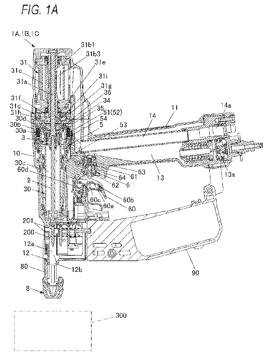
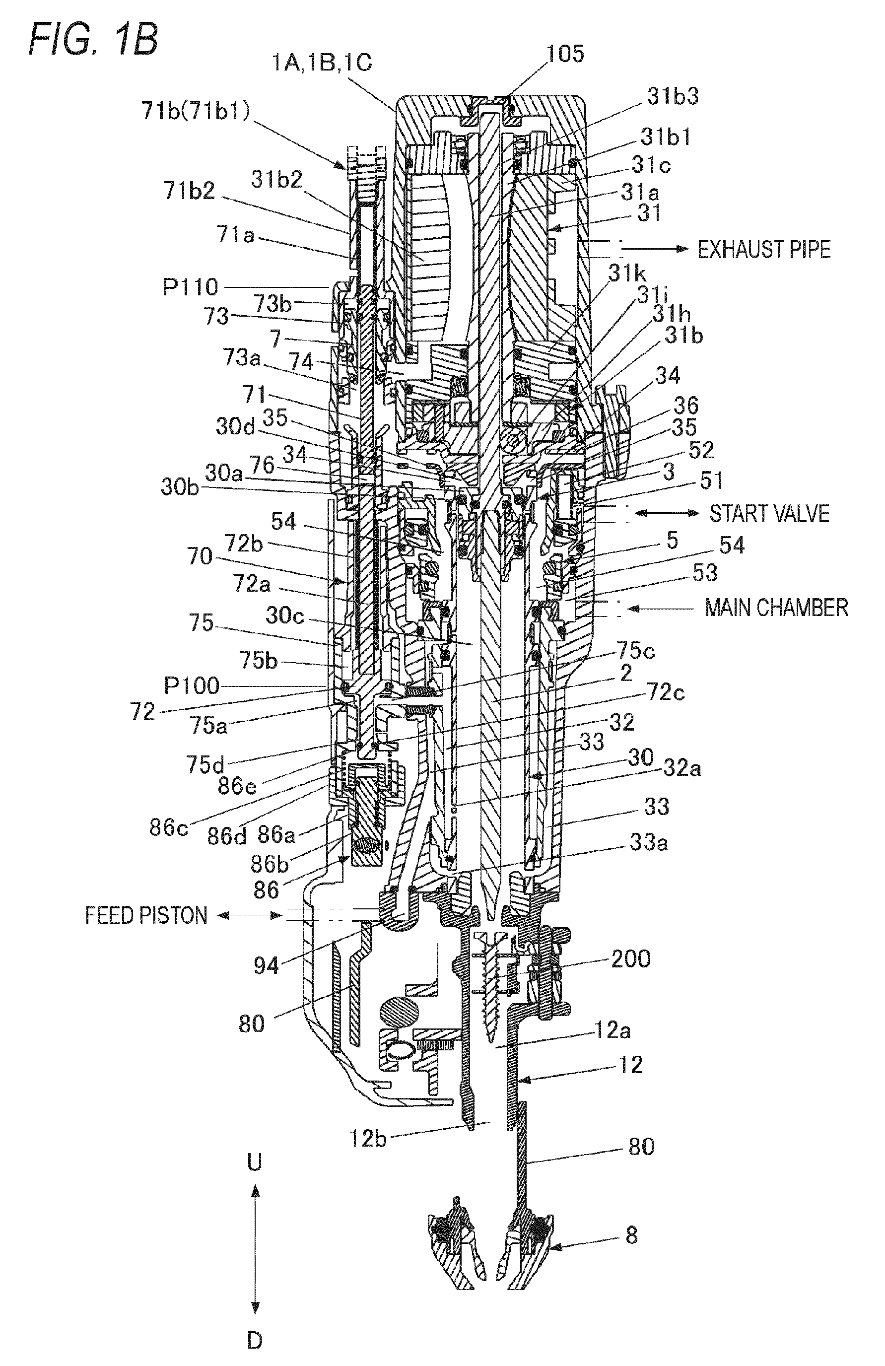


Description
- The present disclosure relates to a screw driving machine that performs tightening after driving a screw into a driven member.
- The screw driving machine is a tool that operates by using compressed air as a power source, causes a driver bit to move in an axial direction by a driving cylinder to drive a screw such that a head portion of the screw is lifted from a driven member, and then cause the driver bit to rotate by an air motor to tighten the screw to the driven member.
- In such a screw driving machine, when the screw is driven, a tip of the screw needs to be driven to penetrate an upper material of the driven member and to a middle of a lower material thereof. However, when the screw is excessively driven, a hole larger than a screw diameter is deeply bored in the lower material, and thus there is a possibility that an engagement amount of the screw is short and a fastening force is weakened.
- Therefore, there has been proposed a pneumatic tool including a driving force adjustment mechanism capable of adjusting a driving force of a screw to appropriately adjust a driving depth of the screw with respect to a driven member to a normal level (for example, see
JP5110301B - In a pneumatic tool in the related art, a driving force adjustment mechanism capable of adjusting a driving force by adjusting an amount of compressed air supplied from a main air chamber to a driving cylinder is provided on an upper portion of a cylinder cap of the driving cylinder. Therefore, the driving force adjustment mechanism is a factor that increases an overall height of the pneumatic tool. In addition, there has been proposed a pneumatic tool in which an air motor that causes a driver bit to rotate is provided on an upper side of a driving cylinder. However, in the configuration in which the air motor is provided on the upper side of the driving cylinder, a disposition of a main valve and a disposition of a valve that controls rotation of the air motor are factors that further increase the overall height of the pneumatic tool.
- Illustrative aspects of the present disclosure provide a screw driving machine in which an increase in the overall height is prevented.
- One illustrative aspect of the present disclosure provides a screw driving machine including: a driving piston to which a driver bit is attachable; a driving cylinder partitioned into a first chamber and a second chamber by the driving piston, the driving cylinder being configured to cause the driver bit to move in an axial direction when compressed air is supplied to the second chamber; an air motor configured to cause the driver bit to rotate about an axis through the driving piston when the compressed air is supplied; an air flow path communicating the second chamber and the air motor communicate with each other; a main chamber configured to store the compressed air, the main chamber communicating with the air flow path; and a main valve configured to open and close communication between the air flow path and the main chamber. The driving cylinder has a supply port communicating the air flow path and the second chamber with each other. The screw driving machine further includes a throttle portion that is disposed so as to be displaceable on an outer periphery of the driving cylinder, the throttle portion being configured to change an opening area of the supply port by being displaced.
- According to the present disclosure, since the throttle portion that changes the opening area of the supply port is provided, the driver bit can move in the axial direction to adjust a force for driving the screw into a driven member. Since the throttle portion that changes the opening area of the supply port is provided on the outer periphery of the driving cylinder, an increase in a length of the screw driving machine along the axial direction of the driver bit is prevented.
- Further, the screw driving machine may further include an on-off valve configured to open and close a second air flow path connecting a first air flow path, which is the air flow path, and the air motor. The air motor is provided on a second chamber side and coaxially with the driving cylinder. The main valve is provided on an outer periphery of the driving cylinder on a driving cylinder side with respect to the air motor along an axial direction of the driving cylinder. The on-off valve is provided on a side portion of the air motor.
- According to the present disclosure, since the main valve is provided on the outer periphery of the driving cylinder and the on-off valve is provided on the side portion of the air motor, an increase in the length of the screw driving machine along the axial direction of the driver bit is prevented. In addition, since the on-off valve is provided on the side portion of the air motor, a length of the second air flow path can be shortened.
- According to the present disclosure, by a configuration including the mechanism that adjusts the force for driving the screw into the driven member, an increase in the length of the screw driving machine along the axial direction of the driver bit can be prevented.
- According to the present disclosure, by a configuration in which the air motor is provided on the second chamber side and coaxially with the driving cylinder, an increase in the length of the screw driving machine along the axial direction of the driver bit can be prevented. In addition, since the length of the air flow path connected to the air motor can be shortened, loss of the compressed air supplied to the air motor can be reduced.
-
-
FIG. 1A is a side sectional view illustrating an example of a screw driving machine according to the present illustrative embodiment; -
FIG. 1B is a front sectional view illustrating the example of the screw driving machine according to the present illustrative embodiment; -
FIG. 1C is a perspective view illustrating the example of the screw driving machine according to the present illustrative embodiment; -
FIG. 1D is a perspective view illustrating the example of the screw driving machine according to the present illustrative embodiment; -
FIG. 1E is an exploded perspective view illustrating an example of a coupling structure of an air motor and a driver bit in the screw driving machine according to the present illustrative embodiment; -
FIG. 1F is an exploded perspective view illustrating the example of the coupling structure of the air motor and the driver bit in the screw driving machine according to the present illustrative embodiment; -
FIG. 2A is a side sectional view of main parts of the screw driving machine according to the present illustrative embodiment illustrating an example of a switching portion; -
FIG. 2B is a side sectional view of the main parts of the screw driving machine according to the present illustrative embodiment illustrating the example of the switching portion; -
FIG. 3A is a bottom sectional view of the main parts of the screw driving machine according to the present illustrative embodiment illustrating the example of the switching portion; -
FIG. 3B is a bottom sectional view of the main parts of the screw driving machine according to the present illustrative embodiment illustrating the example of the switching portion; -
FIG. 4A is a perspective view illustrating an example of a mechanism configured to adjust a force for driving a screw; -
FIG. 4B is a perspective view illustrating the example of the mechanism configured to adjust the force for driving the screw; -
FIG. 5A is a side view of the screw driving machine illustrating an operation example of the mechanism configured to adjust the force for driving the screw; -
FIG. 5B is a side view of the screw driving machine illustrating the operation example of the mechanism configured to adjust the force for driving the screw; -
FIG. 6A is a side view illustrating an example of a lower arm; -
FIG. 6B is a side view illustrating an example of an upper arm; -
FIG. 6C is a side view illustrating an example of a switching member; -
FIG. 7 is a side sectional view of the screw driving machine illustrating an example of an operation of driving a screw into a driven member and tightening the screw; -
FIG. 8A is a front sectional view of the screw driving machine illustrating an example of the operation of driving the screw into the driven member and tightening the screw; -
FIG. 8B is a front sectional view of the screw driving machine illustrating the example of the operation of driving the screw into the driven member and tightening the screw; -
FIG. 8C is a front sectional view of the screw driving machine illustrating the example of the operation of driving the screw into the driven member and tightening the screw; -
FIG. 8D is a front sectional view of the screw driving machine illustrating the example of the operation of driving the screw into the driven member and tightening the screw; -
FIG. 8E is a front sectional view of the screw driving machine illustrating the example of the operation of driving the screw into the driven member and tightening the screw; -
FIG. 8F is a front sectional view of the screw driving machine illustrating the example of the operation of driving the screw into the driven member and tightening the screw; -
FIG. 8G is a front sectional view of the screw driving machine illustrating the example of the operation of driving the screw into the driven member and tightening the screw; -
FIG. 9A is a side sectional view of main parts of the screw driving machine according to the present illustrative embodiment illustrating an example of an operation of driving the screw into the driven member and tightening the screw in a first mode; -
FIG. 9B is a side sectional view of the main parts of the screw driving machine according to the present illustrative embodiment illustrating the example of the operation of driving the screw into the driven member and tightening the screw in the first mode; -
FIG. 10A is a bottom sectional view of the main parts of the screw driving machine according to the present illustrative embodiment illustrating an example of the operation of driving the screw into the driven member and tightening the screw in the first mode; -
FIG. 10B is a bottom sectional view of the main parts of the screw driving machine according to the present illustrative embodiment illustrating the example of the operation of driving the screw into the driven member and tightening the screw in the first mode; -
FIG. 11A is a side sectional view of the main parts of the screw driving machine according to the present illustrative embodiment illustrating an example of the operation of driving the screw into the driven member and tightening the screw in the first mode; -
FIG. 11B is a side sectional view of the main parts of the screw driving machine according to the present illustrative embodiment illustrating the example of the operation of driving the screw into the driven member and tightening the screw in the first mode; -
FIG. 12A is a bottom sectional view of the main parts of the screw driving machine according to the present illustrative embodiment illustrating an example of the operation of driving the screw into the driven member and tightening the screw in the first mode; -
FIG. 12B is a bottom sectional view of the main parts of the screw driving machine according to the present illustrative embodiment illustrating the example of the operation of driving the screw into the driven member and tightening the screw in the first mode; -
FIG. 13A is a side sectional view of main parts of a screw driving machine according to a first modification of the present illustrative embodiment illustrating a modification of the switching portion that switches a driving depth of the screw; -
FIG. 13B is a side sectional view of the main parts of the screw driving machine according to the first modification of the present illustrative embodiment illustrating the modification of the switching portion that switches the driving depth of the screw; -
FIG. 14A is a bottom sectional view of main parts of the screw driving machine according to the first modification of the present illustrative embodiment illustrating the modification of the switching portion; -
FIG. 14B is a bottom sectional view of the main parts of the screw driving machine according to the first modification of the present illustrative embodiment illustrating the modification of the switching portion; -
FIG. 15A is a side sectional view of main parts of a screw driving machine according to the first modification of the present illustrative embodiment illustrating the example of an operation of driving the screw into the driven member and tightening the screw in the first mode; -
FIG. 15B is a side sectional view of the main parts of the screw driving machine according to the first modification of the present illustrative embodiment illustrating the example of the operation of driving the screw into the driven member and tightening the screw in the first mode; -
FIG. 16A is a bottom sectional view of the main parts of a screw driving machine according to the first modification of the present illustrative embodiment illustrating the example of the operation of driving the screw into the driven member and tightening the screw in the first mode; -
FIG. 16B is a bottom sectional view of the main parts of the screw driving machine according to the first modification of the present illustrative embodiment illustrating the example of the operation of driving the screw into the driven member and tightening the screw in the first mode; -
FIG. 17A is a side sectional view of main parts of a screw driving machine according to the first modification of the present illustrative embodiment illustrating an example of an operation of driving the screw into the driven member and tightening the screw in a second mode; -
FIG. 17B is a side sectional view of the main parts of the screw driving machine according to the first modification of the present illustrative embodiment illustrating the example of the operation of driving the screw into the driven member and tightening the screw in the second mode; -
FIG. 18A is a bottom sectional view of the main parts of a screw driving machine according to the first modification of the present illustrative embodiment illustrating the example of the operation of driving the screw into the driven member and tightening the screw in the second mode; -
FIG. 18B is a bottom sectional view of the main parts of the screw driving machine according to the first modification of the present illustrative embodiment illustrating the example of the operation of driving the screw into the driven member and tightening the screw in the second mode; -
FIG. 19A is a front view of main parts of a screw driving machine according to a second modification of the present illustrative embodiment illustrating a state where the screw is driven into the driven member at a first driving depth (1) in the first mode; -
FIG. 19B is a side view of the main parts of the screw driving machine according to the second modification of the present illustrative embodiment illustrating the state where the screw is driven into the driven member at the first driving depth (1) in the first mode; -
FIG. 19C is a bottom view of the main parts of the screw driving machine according to the second modification of the present illustrative embodiment illustrating the state where the screw is driven into the driven member at the first driving depth (1) in the first mode; -
FIG. 20A is a front view of main parts of a screw driving machine according to second modification of the present illustrative embodiment illustrating a state where the screw is driven into the driven member at a first driving depth (2) in the first mode; -
FIG. 20B is a side view of the main parts of the screw driving machine according to the second modification of the present illustrative embodiment illustrating the state where the screw is driven into the driven member at the first driving depth (2) in the first mode; -
FIG. 20C is a bottom view of the main parts of the screw driving machine according to the second modification of the present illustrative embodiment illustrating the state where the screw is driven into the driven member at the first driving depth (2) in the first mode; -
FIG. 21A is a front view of main parts of a screw driving machine according to second modification of the present illustrative embodiment illustrating a state where the screw is driven into the driven member in the second mode; -
FIG. 21B is a side view of the main parts of the screw driving machine according to the second modification of the present illustrative embodiment illustrating the state where the screw is driven into the driven member in the second mode; -
FIG. 21C is a bottom view of the main parts of the screw driving machine according to the second modification of the present illustrative embodiment illustrating the state where the screw is driven into the driven member in the second mode; -
FIG. 22A is a front view of main parts of a screw driving machine according to second modification of the present illustrative embodiment illustrating a sign-in state where the screw is driven into the driven member at the first driving depth (1) in the first mode; -
FIG. 22B is a side view of the main parts of the screw driving machine according to the second modification of the present illustrative embodiment illustrating the sign-in state where the screw is driven into the driven member at the first driving depth (1) in the first mode; -
FIG. 23A is a front view of main parts of a screw driving machine according to second modification of the present illustrative embodiment illustrating a sign-in state where the screw is driven into the driven member at the first driving depth (2) in the first mode; -
FIG. 23B is a side view of the main parts of the screw driving machine according to the second modification of the present illustrative embodiment illustrating the sign-in state where the screw is driven into the driven member at the first driving depth (2) in the first mode; -
FIG. 24A is a front view of main parts of a screw driving machine according to second modification of the present illustrative embodiment illustrating a sign-in state where the screw is driven into the driven member in the second mode; -
FIG. 24B is a side view of the main parts of the screw driving machine according to the second modification of the present illustrative embodiment illustrating the sign-in state where the screw is driven into the driven member in the second mode; -
FIG. 25A is a cross-sectional view illustrating a first modified configuration example of the screw driving machine according to the present illustrative embodiment; -
FIG. 25B is a cross-sectional view illustrating the first modified configuration example of the screw driving machine according to the present illustrative embodiment; -
FIG. 26A is a perspective view of main parts illustrating a second modified configuration example of the screw driving machine according to the present illustrative embodiment; and -
FIG. 26B is a perspective view of the main parts illustrating the second modified configuration example of the screw driving machine according to the present illustrative embodiment. - Hereinafter, illustrative embodiments of a screw driving machine according to the present disclosure will be described with reference to the drawings.
-
FIG. 1A is a side sectional view illustrating an example of the screw driving machine according to the present illustrative embodiment, andFIG. 1B is a front sectional view illustrating the example of the screw driving machine according to the present illustrative embodiment. In addition,FIGS. 1C and1D are perspective views illustrating examples of the screw driving machine according to the present illustrative embodiment. Further,FIGS. 1E and1F are exploded perspective views illustrating examples of a coupling structure of an air motor and a driver bit in the screw driving machine according to the present illustrative embodiment. In addition,FIGS. 2A and2B are side sectional views of main parts of the screw driving machine according to the present illustrative embodiment illustrating an example of a switching portion that switches a driving depth of a screw, andFIGS. 3A and 3B are bottom sectional views of the main parts of the screw driving machine according to the present illustrative embodiment illustrating examples of the switching portion. -
FIGS. 2A and3A illustrate states of respective parts when a first mode in which the driving depth of the screw is set to a first driving depth is selected. In addition,FIG. 2B andFIG. 3B illustrate states of the respective parts when a second mode in which the driving depth of the screw is set to a second driving depth that is deeper than the first driving depth is selected. - A
screw driving machine 1A includes afastening portion 3. The fastening portion is driven by compressed air, causes adriver bit 2 to move in an axial direction, drives ascrew 200 into a drivenmember 300, and then causes thedriver bit 2 to rotate to tighten thescrew 200. Thefastening portion 3 includes a drivingcylinder 30 and anair motor 31. The drivingcylinder 30 is configured to cause thedriver bit 2 to move in the axial direction. Theair motor 31 is configured to causes thedriver bit 2 to rotate around an axis. - In addition, the
screw driving machine 1A includes amain valve 5, astart valve 6, and atrigger 60. Themain valve 5 is configured to switch whether the compressed air is to be supplied to the drivingcylinder 30. Thestart valve 6 is configured to cause themain valve 5 to operate. Thetrigger 60 is configured to cause thestart valve 6 to operate. - Further, the
screw driving machine 1A includes an on-offvalve 7 and acontroller 70. The on-offvalve 7 is configured to switch whether the compressed air is to be supplied to theair motor 31. Thecontroller 70 is configured to cause the on-offvalve 7 to operate. In addition, thescrew driving machine 1A includes acontact arm 8. Thecontact arm 8 is configured to come into contact with the drivenmember 300, be movable in the axial direction along a driving direction of thescrew 200, enable thestart valve 6 to operate in cooperation with an operation of thetrigger 60, and cause thecontroller 70 to operate. - Further, the
screw driving machine 1A includes a drivingdepth regulating portion 4a and a drivingdepth switching portion 4b. The drivingdepth regulating portion 4a is configured to regulate a movement amount of thecontact arm 8 from a bottom dead center position during a driving operation in which the drivingcylinder 30 causes thedriver bit 2 to move in the axial direction. The drivingdepth switching portion 4b is configured to switch whether the movement amount of thecontact arm 8 is to be regulated by the drivingdepth regulating portion 4a. - In addition, the
screw driving machine 1A includes ascrew feeding portion 9 and amagazine 90. Thescrew feeding portion 9 is configured to feed thescrew 200 to anose portion 12 to be described later. Themagazine 90 is configured to accommodate thescrew 200 fed by thescrew feeding portion 9. - The
screw driving machine 1A includes amain body portion 10 and ahandle portion 11. Thehandle portion 11 extends in a direction intersecting themain body portion 10. In thescrew driving machine 1A, thenose portion 12, through which thedriver bit 2 passes when thescrew 200 is supplied by thescrew feeding portion 9, is provided on one side along an extending direction of themain body portion 10 extending along the axial direction of thedriver bit 2. In thescrew driving machine 1A, the one side along the extending direction of themain body portion 10 on which thenose portion 12 is provided is referred to as a lower side, and the other side along the extending direction of themain body portion 10 is referred to as an upper side. - In the
screw driving machine 1A, themagazine 90 is provided on the lower side of thehandle portion 11 in a case where one side of thehandle portion 11 along an extending direction of themain body portion 10 is directed toward the lower side, and themagazine 90 is provided on a front side of thehandle portion 11 in a case where thescrew driving machine 1A is used in a lateral orientation. In addition, in thescrew driving machine 1A, theair motor 31 is provided on the upper side of thehandle portion 11 in the case where the one side of thehandle portion 11 along the extending direction of themain body portion 10 is directed toward the lower side, and theair motor 31 is provided on a rear side of thehandle portion 11 in the case where thescrew driving machine 1A is used in a lateral orientation. - The
nose portion 12 includes aninjection passage 12a and aninjection port 12b. Thescrew 200 coupled by acoupling band 201 is supplied to theinjection passage 12a. Theinjection port 12b is formed in one end portion along an extending direction of theinjection passage 12a indicated by an arrow D. Thescrew 200 separated from thecoupling band 201 is injected from theinjection port 12b. - The
screw driving machine 1A includes amain chamber 13 to which compressed air is supplied from an external air compressor (not illustrated). Themain chamber 13 is provided in thehandle portion 11 and on an outer periphery of the drivingcylinder 30 connected to an inside of thehandle portion 11 in themain body portion 10. Compressed air decompressed by apressure reducing valve 13a is supplied to themain chamber 13. In addition, thescrew driving machine 1A includes anexhaust pipe 14. The compressed air supplied to the drivingcylinder 30, theair motor 31, and the like, is exhausted from theexhaust pipe 14. Theexhaust pipe 14 is provided in thehandle portion 11. The compressed air is exhausted from theexhaust pipe 14 via anexhaust filter 14a. - The driving
cylinder 30 is an example of a driving portion. The drivingcylinder 30 is provided inside themain body portion 10 in a form of extending vertically. The drivingcylinder 30 is provided with adriving piston 30a in a cylindrical internal space so as to be slidable. Thedriving piston 30a includes aseal portion 30b on an outer periphery thereof. Thedriving piston 30a is accommodated in the drivingcylinder 30. Thedriving piston 30a partitions an interior of the drivingcylinder 30 into afirst chamber 30c which is a lower chamber of the driving cylinder and asecond chamber 30d which is an upper chamber of the driving cylinder. Amotor shaft 31a is attached to thedriving piston 30a. Themotor shaft 31a is driven by theair motor 31. In a state where thedriving piston 30a is at the top dead center position, thedriver bit 2 is connected to afirst chamber 30c side. That is, thedriver bit 2 is detachably attached to thedriving piston 30a via themotor shaft 31a in a form of protruding from thedriving piston 30a toward the lower side. In addition, themotor shaft 31a is provided on a side opposite to thedriver bit 2 with respect to thedriving piston 30a. Themotor shaft 31a is attached to thedriving piston 30a in a form of protruding from thedriving piston 30a toward the upper side. - In the driving
cylinder 30, the compressed air is supplied from themain chamber 13 to thesecond chamber 30d. Thedriving piston 30a is pressed by an air pressure of the compressed air supplied to thesecond chamber 30d of the drivingcylinder 30 and moves in a downward direction indicated by an arrow D, which is a first direction, to cause thedriver bit 2 to move in the downward direction along the axial direction. Thedriver bit 2 and themotor shaft 31a move integrally with thedriving piston 30a. Thedriver bit 2 that moves in the downward direction is guided by theinjection passage 12a of thenose portion 12, thereby driving thescrew 200 supplied from themagazine 90 to theinjection passage 12a of thenose portion 12 into the drivenmember 300. In addition, when themotor shaft 31a rotates, thedriver bit 2 rotates integrally with themotor shaft 31a to fasten thescrew 200 driven into the drivenmember 300. - The
screw driving machine 1A includes atimer chamber 32 and ablowback chamber 33. Thetimer chamber 32 is supplied with the compressed air for causing thecontroller 70 to operate. Theblowback chamber 33 causes thedriving piston 30a moved to the bottom dead center position to return to the top dead center position and is supplied with the compressed air for causing thescrew feeding portion 9 to operate. - The
timer chamber 32 and theblowback chamber 33 are provided on an outer peripheral side of the drivingcylinder 30 inside themain body portion 10. Thetimer chamber 32 is in communication with a space in the drivingcylinder 30 via a sidehole flow path 32a of the drivingcylinder 30. In addition, theblowback chamber 33 is in communication with the space in the drivingcylinder 30 via a sidehole flow path 33a of the drivingcylinder 30. In thetimer chamber 32 and theblowback chamber 33, the compressed air is supplied by an operation of thedriving piston 30a moving from the top dead center position to the bottom dead center position, and pressure increases according to a position of thedriving piston 30a. - The
air motor 31 is an example of a tightening unit. Theair motor 31 includes a rotor 31b1, a blade 31b2, and amotor housing 31c. The rotor 31b1 is configured to rotate when the compressed air is supplied. The blade 31b2 is configured to receive a flow of air for causing the rotor 31b1 to rotate. Themotor housing 31c rotatably supports the rotor 31b1 and is configured to generate the flow of air for causing the rotor 31b1 to rotate. In theair motor 31, rotation of the rotor 31b1 is transmitted to themotor shaft 31a via aspeed reducer 31d. Thespeed reducer 31d is provided between the drivingcylinder 30 and theair motor 31. Thespeed reducer 31d is configured by a planetary gear mechanism. Thespeed reducer 31 includes asun gear 31e connected to the rotor 31b1, a plurality ofplanetary gears 31f meshing with thesun gear 31e, anouter gear 31g meshing with theplanetary gears 31f, and acarrier 31h rotatably supporting theplanetary gears 31f. In thespeed reducer 31d, thesun gear 31e, theplanetary gears 31f, and theouter gear 31g are provided on the same surface in the axial direction of thedriver bit 2. In addition, in thespeed reducer 31d, thecarrier 31h is provided on the lower side of thesun gear 31e, theplanetary gears 31f, and theouter gear 31g. - The rotor 31b1 has a hollow structure in which a hole portion 31b3 is provided so as to penetrate from an upper end to a lower end in the axial direction along an upward direction indicated by an arrow U and the downward direction indicated by the arrow D. The
motor shaft 31a is inserted into the hole portion 31b3 so as to be movable in the axial direction. The hole portion 31b3 is provided coaxially with a center of rotation of the rotor 31b1. The rotor 31b1 is provided with an engagement position connected to thesun gear 31e on the lower end thereof. The engagement position connected to thesun gear 31e is configured by a polygonal shaft, for example, a hexagonal shaft, and in thesun gear 31e, an engagement position connected to the rotor 31b1 is formed by a polygonal hole, for example, a hexagonal hole. Theouter gear 31g has teeth formed on an inner peripheral surface of an annular member, and is non-rotatably fixed concentrically with thesun gear 31e. Theplanetary gear 31f is rotatably supported by ashaft 31j provided on thecarrier 31h, and meshes with thesun gear 31e and theouter gear 31g in a form of being interposed between thesun gear 31e and theouter gear 31g. Accordingly, in thespeed reducer 31d, when thesun gear 31e rotates as therotor 3 1b1 rotates, thecarrier 31h rotates at a predetermined reduction ratio while theplanetary gear 31f rotates. - The
carrier 31h is an example of a drive force transmission portion. Thecarrier 31h supports themotor shaft 31a to be movable in the axial direction and transmits the rotation of the rotor 31b1 to themotor shaft 31a. Thecarrier 31h includes a plurality ofgear rollers 31i that support themotor shaft 31a to be movable in the axial direction. Thegear rollers 31i are rotatably supported by thecarrier 31h in a disposition in which outer peripheral surfaces thereof are positioned on sides of a polygon, for example, a triangle, surrounding a center of rotation of thecarrier 31h. Themotor shaft 31a has a configuration in which a position in contact with thegear roller 31i is a flat surface. Themotor shaft 31a has three flat surfaces in accordance with the disposition of thegear rollers 31i. Accordingly, themotor shaft 31a is supported at the center of rotation of thecarrier 31h by the plurality ofgear rollers 31i, and is movable in the axial direction by rotation of thegear rollers 31i. Thus, when thedriving piston 30a moves in the downward direction in the drivingcylinder 30 due to the air pressure of the compressed air, themotor shaft 31a moves in the downward direction integrally with thedriving piston 30a and thedriver bit 2. - When the flat surface of the
motor shaft 31a comes into contact with thegear roller 31i, themotor shaft 31a rotates together with thecarrier 31h. Thus, when therotor 3 1b1 of theair motor 31 rotates due to the air pressure of the compressed air, themotor shaft 31a rotates together with thecarrier 31h rotating at the predetermined reduction ratio. In thespeed reducer 31b, theouter gear 31g is non-rotatably attached to acase 31k via a seal member 31m1. In addition, in thespeed reducer 31b, thecarrier 31h is rotatably inserted into acase cover 31n that closes thecase 31k via a seal member 31m2, and theplanetary gear 31f rotatably attached to theshaft 31j of thecarrier 31h meshes with theouter gear 31g. In addition, in thespeed reducer 31b, thesun gear 31e engaged with the rotor 31b1 is inserted into theouter gear 31g via a seal member 31m3 between thecarrier 31h and thesun gear 31e, and is meshed with theplanetary gear 3 1f. Thespeed reducer 3 1b constitutes a part of anair flow path 74 to be described later in thecase 31k. - The
air motor 31 is provided on the upper side of themain body portion 10. In theair motor 31, themotor shaft 31a is provided coaxially with thedriver bit 2. Accordingly, theair motor 31 is provided coaxially with the drivingcylinder 30 on asecond chamber 30d side with respect to the drivingcylinder 30, that is, on a side opposite to the lower side on which thenose portion 12 is provided in themain body portion 10 and on the upper side of the drivingcylinder 30 along the axial direction of thedriver bit 2. In addition, with a configuration in which themotor shaft 31a is inserted into the hole portion 31b3 provided in the rotor 31b1 and a configuration in which theair motor 31 is provided on the upper side of the drivingcylinder 30, theair motor 31 ensures a space in which themotor shaft 31a moving in an up-down direction operates. - The
main valve 5 is vertically movably provided on an outer peripheral side of the drivingcylinder 30. In addition, themain valve 5 is biased by amain valve spring 51 in the downward direction, which is a direction in which anair flow path 54 is closed. Further, in themain valve 5, the compressed air is supplied, via thestart valve 6, from themain chamber 13 to a main valveupper chamber 52 in which themain valve spring 51 is provided, and themain valve 5 is pressed in the downward direction by the air pressure of the compressed air. In addition, in themain valve 5, the compressed air is supplied from themain chamber 13 to a main valvelower chamber 53, and themain valve 5 is pressed in the upward direction by the air pressure of the compressed air. - Accordingly, the
main valve 5 opens and closes theair flow path 54 connecting themain chamber 13, the drivingcylinder 30, and theair motor 31. Theair flow path 54 is an example of a first air flow path. Theair flow path 54 is provided between the drivingcylinder 30 and themain valve 5 on an inner peripheral side of themain valve 5 and on the outer peripheral side of the drivingcylinder 30 and is connected to the main valvelower chamber 53 via themain valve 5. When themain valve 5 is not in operation, themain valve 5 is biased in the downward direction to be located at the bottom dead center position based on a relation, the relation being of a force of themain valve spring 51 and a balance between the air pressure of the compressed air supplied to the main valveupper chamber 52 and the air pressure of the compressed air supplied to the main valvelower chamber 53, thereby blocking theair flow path 54 between the main valvelower chamber 53 and the drivingcylinder 30. On the other hand, when themain valve 5 is in operation, themain valve 5 is pressed in the upward direction by the air pressure of the compressed air supplied from themain chamber 13 to the main valvelower chamber 53 when the main valveupper chamber 52 is in communication with the atmosphere via thestart valve 6, thereby opening theair flow path 54 between the main valvelower chamber 53 and the drivingcylinder 30. -
FIGS. 4A and4B are perspective views illustrating examples of a mechanism that adjusts a force for driving a screw, andFIGS. 5A and5B are side views of the screw driving machine illustrating an operation example of the mechanism that adjusts the force for driving the screw. - The
screw driving machine 1A includes asupply port 34 and athrottle portion 35. Thesupply port 34 connects theair flow path 54 and the drivingcylinder 30 on a downstream side of themain valve 5. Thethrottle portion 35 is configured to switch an opening area of thesupply port 34. Thesupply port 34 is provided in a side surface of an upper portion of the drivingcylinder 30. Thesupply port 34 is formed by an opening that penetrates a side wall of the drivingcylinder 30 and connects an outer side and an inner side of the drivingcylinder 30. - The
throttle portion 35 includes acylindrical portion 35a and a plate-like flange portion 35b. Thecylindrical portion 35a contacts the outer periphery of the drivingcylinder 30. The plate-like flange portion 35b protrudes from thecylindrical portion 35a toward an outer side direction. Thethrottle portion 35 is vertically movably provided along the outer periphery of the drivingcylinder 30 at a portion where thesupply port 34 is provided. - The
screw driving machine 1A includes a flowrate switching member 36 that is engageable with thethrottle portion 35. The flowrate switching member 36 is an example of a flow rate switching portion. The flowrate switching member 36 is formed by a plate-like member. The flowrate switching member 36 is provided so as to overlap the upper side of theflange portion 35b of thethrottle portion 35 on the outer periphery of the drivingcylinder 30. The flowrate switching member 36 is configured to be rotatable about a shaft of the drivingcylinder 30 that is coaxial with the axial direction of thedriver bit 2. - The
throttle portion 35 includes acam surface 37a that converts rotation of the flowrate switching member 36 into movement of thethrottle portion 35 in the axial direction of the drivingcylinder 30. In addition, the flowrate switching member 36 includes an engagingportion 37b that follows thecam surface 37a. Thecam surface 37a is an example of a cam portion. The cam surface 37 is formed by a surface inclined in the axial direction of the drivingcylinder 30 along a rotation direction of the flowrate switching member 36. The engagingportion 37b is an example of the cam portion. The engagingportion 37b is configured by a convex portion that protrudes in a direction from the flowrate switching member 36 toward thethrottle portion 35 and is in contact with thecam surface 37a. - The
throttle portion 35 is biased by a biasingmember 35c such as a coil spring in a direction in which theflange portion 35b approaches the flowrate switching member 36. Accordingly, thethrottle portion 35 and the flowrate switching member 36 are engaged with thecam surface 37a via the engagingportion 37b in a form in which the engagingportion 37b is in contact with thecam surface 37a. - The
throttle portion 35 does not rotate with respect to the drivingcylinder 30, and a portion of thecam surface 37a with which the engagingportion 37b of the flowrate switching member 36 comes into contact changes as the flowrate switching member 36 rotates. Accordingly, thethrottle portion 35 moves in a direction approaching and a direction separating from the flowrate switching member 36 according to the rotation direction of the flowrate switching member 36, thereby moving along the axial direction of the drivingcylinder 30 interlocking with the rotation of the flowrate switching member 36, and switching a size of the opening area of thesupply port 34. - The
screw driving machine 1A includes anoperation member 38 configured to cause the flowrate switching member 36 to rotate. Theoperation member 38 includes anoperation portion 38a, ashaft portion 38b, and agear 38c. Theoperation portion 38a receives an operation of causing the flowrate switching member 36 to rotate. Theshaft portion 38b protrudes from theoperation portion 38a. Thegear 38c is provided on theshaft portion 38b. In theoperation member 38, theoperation portion 38a is exposed to an outside of themain body portion 10, and theoperation portion 38a can be operated from the outside of themain body portion 10. - In the
operation member 38, when theoperation portion 38a is operated, thegear 38c rotates about theshaft portion 38b as a fulcrum. Thegear 38c meshes with agear 36a provided on an outer periphery of the flowrate switching member 36. Accordingly, in theoperation member 38, when theoperation portion 38a is operated, thegear 38c rotates about theshaft portion 38b as a fulcrum, and thus the flowrate switching member 36 in which thegear 38c and thegear 36a mesh with each other rotates. - In the
operation member 38, a material or the like of the drivenmember 300 is indicated on theoperation portion 38a as a guide for selecting a force for driving thescrew 200. Theoperation member 38 is configured to operate theoperation portion 38a in a direction in which an indication of a desired material can be seen, as illustrated inFIGS. 5A and5B , according to the material of the drivenmember 300 that performs driving and tightening of thescrew 200, thereby switching the size of the opening area of thesupply port 34 in accordance with the material or the like of the drivenmember 300. - The
start valve 6 includes apilot valve 61, avalve stem 62, and avalve stem spring 63. Thepilot valve 61 is configured to open and close the main valveupper chamber 52. The valve stem 62 is configured to cause thepilot valve 61 to operate. The valve stemspring 63 is configured to bias thepilot valve 61 in the upward direction and to bias thevalve stem 62 in the downward direction. - In the
start valve 6, thepilot valve 61 is pressed in the downward direction due to the air pressure of the compressed air supplied from themain chamber 13. In addition, in thestart valve 6, thepilot valve 61 is pressed in the upward direction due to the air pressure of the compressed air supplied from themain chamber 13 to a valvelower chamber 64. - Accordingly, in the
start valve 6, thepilot valve 61 is held at an upper position based on a relation between a balance of the air pressure of the compressed air and a force of thevalve stem spring 63. In contrast, in thestart valve 6, when thevalve stem 62 moves in the upward direction, the valvelower chamber 64 is in communication with the atmosphere, and thus thepilot valve 61 moves in the downward direction due to the air pressure of the compressed air. Further, when thepilot valve 61 moves in the downward direction, a passage through which the main valveupper chamber 52 communicates with the atmosphere is opened. - The
trigger 60 is provided on the lower side of thehandle portion 11 and rotates about 60c as a fulcrum in response to an operation of an operator. Thetrigger 60 is biased in the direction separating from thevalve stem 62 of thestart valve 6 by atrigger spring 60d. - The
trigger 60 includes acontact lever 60a that causes thevalve stem 62 of thestart valve 6 to operate. Thecontact lever 60a is supported by thetrigger 60 so as to be rotatable about ashaft 60b as a fulcrum. Thecontact lever 60a does not come into contact with thevalve stem 62 only in a state where an operation of pulling thetrigger 60 is performed. In contrast, when thecontact lever 60a is pressed by anupper arm 81 to be described later of thecontact arm 8 in the state where the operation of pulling thetrigger 60 is performed, thevalve stem 62 is caused to move in the upward direction. When the operation of pulling thetrigger 60 is performed in a state where thecontact lever 60a is pressed by theupper arm 81, thecontact lever 60a causes thevalve stem 62 to move in the upward direction. Accordingly, thestart valve 6 is operated by a combination of an operation of thetrigger 60 and an operation of being pressed by thecontact arm 8. An order of the operation of thetrigger 60 and the operation of being pressed by thecontact arm 8 is optional. - The on-off
valve 7 is vertically movably supported by an on-offvalve cylinder 73 provided in themotor housing 31c. In the on-offvalve cylinder 73, an on-off valvelower chamber 73a is provided on the lower side of the on-offvalve 7 indicated by the arrow D, and an on-off valveupper chamber 73b is provided on the upper side of the on-offvalve 7 indicated by the arrow U. The on-offvalve 7 is operated by the compressed air supplied from themain chamber 13 and, in a state where the compressed air is not supplied to the on-off valveupper chamber 73b, the on-offvalve 7 moves in the upward direction indicated by the arrow U due to the compressed air supplied to the on-off valvelower chamber 73a. In addition, when the compressed air is supplied to the on-off valveupper chamber 73b, the on-off valveupper chamber 73b moves in the downward direction as indicated by the arrow D. - The on-off
valve 7 is configured to open and close theair flow path 74 connected to theair motor 31 by moving in the up-down direction. Theair flow path 74 is an example of a second air flow path. Theair flow path 74 is in communication with theair flow path 54 on the downstream side of themain valve 5 and on an upstream side of thesupply port 34. In theair flow path 74, a flow of air between themain chamber 13 and theair motor 31 is blocked when the on-offvalve 7 moves in the downward direction and is closed. In addition, in theair flow path 74, when the on-offvalve 7 moves in the upward direction and opens, communication between themain chamber 13 and theair motor 31 is established. The on-offvalve 7 is provided on a side portion of theair motor 31. Acontroller cover 77 covering the on-offvalve 7, thecontroller 70, and the like is fixed to themain body portion 10 by ascrew 77a. - The
controller 70 includes acontrol valve cylinder 75, afirst control valve 72, acommunication passage 75c, and asecond control valve 71. Thefirst control valve 72 is accommodated in thecontrol valve cylinder 75 and partitions an inside of thecontrol valve cylinder 75 into athird chamber 75a and afourth chamber 75b. Thecommunication passage 75c allows the inside of the drivingcylinder 30 and thethird chamber 75a in thecontrol valve cylinder 75 to communicate with each other via thetimer chamber 32. Thesecond control valve 71 is located on an arrow U direction side with respect to thefirst control valve 72 and is disposed away from thefirst control valve 72. - In addition, the
controller 70 includes afirst biasing member 72b and asecond biasing member 71b. Thefirst biasing member 72b is a first biasing portion configured to bias thefirst control valve 72 in an arrow D direction. Thesecond biasing member 71a is a second biasing portion configured to bias thesecond control valve 71 in an arrow D direction. - In the
control valve cylinder 75, thethird chamber 75a is provided on the lower side of thefirst control valve 72 indicated by the arrow D, and thefourth chamber 75b is provided on the upper side of thefirst control valve 72 indicated by the arrow U. In thecontrol valve cylinder 75, thethird chamber 75a is in communication with thetimer chamber 32 via thecommunication passage 75c, and is in communication with the space in the drivingcylinder 30 via thetimer chamber 32. In addition, in thecontrol valve cylinder 75, thethird chamber 75a is in communication with an outside of a body of thescrew driving machine 1A via anexhaust passage 75d. - The
first control valve 72 is vertically movably supported by thecontrol valve cylinder 75 along the upward direction indicated by the arrow U and the downward direction indicated by the arrow D. In addition, in thefirst control valve 72, a rod-shapedcoupling portion 72a extending in the up-down direction is coupled in a form protruding in the upward direction indicated by the arrow U. Further, thefirst control valve 72 is biased in the arrow D direction by thefirst biasing member 72b such as a coil spring. - The
first control valve 72 is configured to be movable to a standby position P100 which is the bottom dead center position by moving in the downward direction indicated by the arrow D, and is configured to be movable to a later-described operation completion position which is the top dead center position by moving in the upward direction indicated by the arrow U. - The
first control valve 72 moves to the standby position P100 by being biased in the arrow D direction by thefirst biasing member 72b. - The
first control valve 72 includes aseal portion 72c that opens and closes theexhaust passage 75d. In a state where thefirst control valve 72 stands by at the standby position P100, theseal portion 72c moves to a position to open theexhaust passage 75d, and thethird chamber 75a of thecontrol valve cylinder 75 is in communication with the outside of the body of thescrew driving machine 1A via theexhaust passage 75d. When thefirst control valve 72 moves to a later-described pressure control start position between the standby position P100 and the operation completion position in a process of moving from the standby position P100 to the operation completion position, theseal portion 72c moves to a position to close theexhaust passage 75d. - The
first control valve 72 standing by at the standby position P100 is pressed and operated by a later-describedlower arm 80 of thecontact arm 8 via a tighteningdepth adjusting portion 86, and moves from the standby position P100 to the pressure control start position. In addition, when thefirst control valve 72 moves to the pressure control start position, thefirst control valve 72 is operated due to the compressed air supplied from thetimer chamber 32 and moves from the pressure control start position to the operation completion position. In the process of moving from the pressure control start position to the operation completion position, thefirst control valve 72 presses thesecond control valve 71 via thecoupling portion 72a to cause thesecond control valve 71 to operate. - The
second control valve 71 is configured by a rod-shaped member extending in the up-down direction, and is vertically movably supported with respect to the on-offvalve 7. Thesecond control valve 71 moves to a standby position P110 by being biased in the arrow D direction by thesecond biasing member 71a. In addition, thesecond control valve 71 is operated by being pressed by thefirst control valve 72. Thesecond control valve 71 is movable from the standby position P110 to the later-described operation completion position and is configured to cause the on-offvalve 7 to operate by switching whether the compressed air is to be supplied to the on-off valveupper chamber 73b of the on-offvalve cylinder 73. - In the
controller 70, thefirst control valve 72 and thesecond control valve 71 are configured by independent members. In thecontroller 70, aseparation portion 76 is formed separating thefirst control valve 72 moved to the standby position P100 and thesecond control valve 71 moved to the standby position P110. Theseparation portion 76 is configured by providing a space between an upper end of thecoupling portion 72a, which is an upper end of thefirst control valve 72, and a lower end of thesecond control valve 71. - In the
controller 70, in a state where thelower arm 80 is moved to the bottom dead center position, since thelower arm 80 does not come into contact with the tighteningdepth adjusting portion 86, the tighteningdepth adjusting portion 86 does not come into contact with thefirst control valve 72. In a state where the tighteningdepth adjusting portion 86 is not in contact with thefirst control valve 72, thefirst control valve 72 is biased by thefirst biasing member 72b and moves to the standby position P100, and thesecond control valve 71 is biased by thesecond biasing member 71a and moves to the standby position P110. Then, thefirst control valve 72 and thesecond control valve 71 are separated by theseparation portion 76. - In the
controller 70, when thelower arm 80 moves to the top dead center position, thefirst control valve 72 is pressed in the upward direction via the tighteningdepth adjusting portion 86 and moves from the standby position P100 to the pressure control start position. During a period until thefirst control valve 72 moves from the standby position P100 to the pressure control start position, thesecond control valve 71 standing by at the standby position P110 and thefirst control valve 72 moving to the pressure control start position are maintained in a state of being separated from each other by theseparation portion 76. Accordingly, a configuration is provided such that the upper end of thefirst control valve 72 and the lower end of thesecond control valve 71 are not in contact with each other with a movement amount of thefirst control valve 72 due to movement of thelower arm 80 from the bottom dead center position to the top dead center position. - In the
controller 70, by moving thefirst control valve 72 to the pressure control start position, thefirst control valve 72 is operated due to the compressed air supplied from thetimer chamber 32, and when thefirst control valve 72 moves in the upward direction from the pressure control start position, thefirst control valve 72 is separated from the tighteningdepth adjusting portion 86. Further, when thefirst control valve 72 moves to a second control valve operation start position between the pressure control start position and the operation completion position in the process of moving from the pressure control start position to the operation completion position, the upper end of thefirst control valve 72 comes into contact with the lower end of thesecond control valve 71, and thesecond control valve 71 is pressed in the upward direction by thefirst control valve 72. In a state where thefirst control valve 72 has moved to the operation completion position and thesecond control valve 71 has moved to the operation completion position, thefirst control valve 72 and thesecond control valve 71 are not separated from each other. - The
screw feeding portion 9 includes a feedingmember 91 and afeed piston 92. The feedingmember 91 is configured to feed thescrew 200. Thefeed piston 92 is configured to cause the feedingmember 91 to operate. The feedingmember 91 is supported so as to be movable in a direction approaching and a direction separating from thenose portion 12. The feedingmember 91 is configured to feed thescrew 200 coupled by thecoupling band 201 to theinjection passage 12a of thenose portion 12 by locking with a claw portion (not illustrated). - The
feed piston 92 is coupled to the feedingmember 91 and is provided in afeed cylinder 93 so as to be slidable. Thefeed cylinder 93 is connected to theblowback chamber 33 via afeed flow path 94, and is supplied with compressed air from theblowback chamber 33. - The
feed piston 92 is operated by an air pressure of the compressed air supplied from theblowback chamber 33 to cause the feedingmember 91 to move in the direction separating from thenose portion 12. In addition, when the feedingmember 91 is biased by the biasingmember 95 such as a coil spring in the direction approaching thenose portion 12 and the air pressure in thefeed cylinder 93 decreases, thefeed piston 92 causes the feedingmember 91 to move in the direction approaching thenose portion 12 by biasing of the biasingmember 95. - The
magazine 90 is provided on the lower side of thehandle portion 11 and is coupled to thenose portion 12. In themagazine 90, a plurality ofscrews 200 are coupled by thecoupling band 201, and a screw coupling body in a form of, for example, a spiral shape is accommodated. - The
contact arm 8 is an example of a contact portion. Thecontact arm 8 includes thelower arm 80 that comes into contact with the drivenmember 300 and theupper arm 81 configured to cause a pressingmember 87 that presses thecontact lever 60a of thetrigger 60 to operate. In addition, thecontact arm 8 includes aroller 82 that transmits movement of thelower arm 80 to theupper arm 81. Thecontact arm 8 is configured to be movable in the downward direction indicated by the arrow D, which is the first direction, and the upward direction indicated by the arrow U, which is the second direction opposite to the first direction. Thecontact arm 8 is configured such that thelower arm 80 and theupper arm 81 are interlockingly movable along moving directions of thelower arm 80 indicated by the arrows U and D. In addition, thecontact arm 8 is configured such that the interlocking between thelower arm 80 and theupper arm 81 is released, and thelower arm 80 is movable independently of theupper arm 81. Thecontact arm 8 can move from a first position to a second position via a third position, the first position being the bottom dead center position of thelower arm 80, the second position being the top dead center position of thelower arm 80, and the third position being a sign-in position serving as a starting point of an operation of causing thedriver bit 2 to move in the axial direction to drive thescrew 200. - The
lower arm 80 is an example of a first arm, is supported by thenose portion 12 of thescrew driving machine 1A so as to be movable in the up-down direction, and is biased in the downward direction by a biasingmember 83a. The biasingmember 83a is configured by a coil spring or the like. -
FIG. 6A is a side view illustrating an example of the lower arm. Thelower arm 80 includes acam groove 84. Thecam groove 84 is configured to switch whether thelower arm 80 and theupper arm 81 are to be interlocked with each other and to switch relative positions of thelower arm 80 and theupper arm 81 along the moving direction of thelower arm 80. In addition, thelower arm 80 includes a bottom dead center position switchingaffected portion 85. The bottom dead center position switchingaffected portion 85 receives a force that causes thelower arm 80 to move in the upward direction by relative movement with respect to themain body portion 10 when the relative positions of thelower arm 80 and theupper arm 81 are switched. - The
cam groove 84 includes a firstengaging portion 84a and a firstengagement releasing portion 84b. The firstengaging portion 84a interlockingly engages thelower arm 80 and theupper arm 81 via theroller 82. The firstengagement releasing portion 84b releases the interlocking engagement between thelower arm 80 and theupper arm 81 by the first engagingportion 84a via theroller 82, thereby allowing thelower arm 80 to move independently with respect to theupper arm 81. In addition, thecam groove 84 includes a secondengaging portion 84c and a secondengagement releasing portion 84d. The secondengaging portion 84c interlockingly engages thelower arm 80 and theupper arm 81 via theroller 82. The secondengagement releasing portion 84d releases the interlocking engagement between thelower arm 80 and theupper arm 81 by the second engagingportion 84c via theroller 82, thereby allowing thelower arm 80 to move independently with respect to theupper arm 81. - The first
engaging portion 84a is a portion above thecam groove 84 extending in the up-down direction. The firstengaging portion 84a is provided on a surface located on the lower side among surfaces of thecam groove 84 facing each other in the up-down direction. The firstengaging portion 84a intersects the moving directions of thelower arm 80 indicated by the arrows U and D, and is formed by a surface capable of pressing theroller 82 in the upward direction indicated by the arrow U by an operation of moving thelower arm 80 in the arrow U direction. The firstengagement releasing portion 84b is configured by a surface that extends from the first engagingportion 84a in an oblique downward direction and guides theroller 82 in a lateral direction intersecting the movement direction of thelower arm 80. - The second
engaging portion 84c is a portion connected to a lower end of the firstengagement releasing portion 84b in thecam groove 84. The secondengaging portion 84c is provided on a surface located on the lower side among the surfaces of thecam groove 84 facing each other in the up-down direction. The secondengaging portion 84c is configured by a surface that intersects the moving directions of thelower arm 80 indicated by the arrows U and D and presses theroller 82 in the upward direction indicated by the arrow U by the operation of moving thelower arm 80 in the arrow U direction. The secondengagement releasing portion 84d is configured by a surface that extends from the second engagingportion 84c in an oblique downward direction and guides theroller 82 in the lateral direction intersecting the movement direction of thelower arm 80. - Accordingly, in the
cam groove 84, the first engagingportion 84a, the firstengagement releasing portion 84b, the second engagingportion 84c, and the secondengagement releasing portion 84d are surfaces connected in a substantially crank shape, and when a position with which theroller 82 comes into contact is changed, the interlocking engagement between thelower arm 80 and theupper arm 81 via theroller 82 and releasing of the interlocking engagement between thelower arm 80 and theupper arm 81 are switched. - The
upper arm 81 is an example of a second arm. Theupper arm 81 is supported by a side portion of themain body portion 10 of thescrew driving machine 1A so as to be movable in the up-down direction, and is biased in the downward direction by a biasingmember 83b configured by a coil spring or the like. -
FIG. 6B is a side view illustrating an example of the upper arm. Theupper arm 81 has aguide groove 81a to which movement of thelower arm 80 is transmitted via theroller 82. A length of theguide groove 81a in a short direction is slightly longer than a diameter of theroller 82, and a longitudinal direction of theguide groove 81a extends in a direction intersecting the moving direction of theupper arm 81 and the moving direction of thelower arm 80 illustrated inFIG. 6B and the like. - The
roller 82 is an example of a transmission member. Theroller 82 is inserted into thecam groove 84 of thelower arm 80 and theguide groove 81a of theupper arm 81. Theroller 82 is formed to have a cylindrical shape rotatable along thecam groove 84 and theguide groove 81a. Theroller 82 is biased by a biasingmember 82a such as a torsion coil spring in a direction in which theroller 82 is pressed against the first engagingportion 84a, the firstengagement releasing portion 84b, the second engagingportion 84c, and the secondengagement releasing portion 84d. - The first
engaging portion 84a is a surface in the direction intersecting the moving direction of thelower arm 80. Therefore, when thelower arm 80 moves in the upward direction due to the relative movement with respect to themain body portion 10 in a state where theroller 82 is located at a position facing the first engagingportion 84a, thecam groove 84 provided in thelower arm 80 moves in the upward direction, and the first engagingportion 84a comes into contact with theroller 82 from the lower side and presses theroller 82 in the upward direction. In addition, theroller 82 pressed in the upward direction by the first engagingportion 84a of thecam groove 84 presses a surface on the upper side of theguide groove 81a in the upward direction. Accordingly, in a state where theroller 82 is in contact with the first engagingportion 84a, the movement of thelower arm 80 is in a state of being able to be transmitted to theupper arm 81 via the first engagingportion 84a and theroller 82, and the first engagingportion 84a interlockingly engages thelower arm 80 and theupper arm 81 via theroller 82. - On the other hand, the first
engagement releasing portion 84b extends from the first engagingportion 84a in the oblique downward direction. Therefore, when thelower arm 80 moves in the upward direction due to the relative movement with respect to themain body portion 10 in a state where theroller 82 is at a position facing the firstengagement releasing portion 84b, a force is generated for the firstengagement releasing portion 84b to press theroller 82 in the lateral direction. Thus, the firstengagement releasing portion 84b guides theroller 82 along theguide groove 81a of theupper arm 81 in the direction intersecting the moving direction of thelower arm 80. Accordingly, in a state where theroller 82 is in contact with the firstengagement releasing portion 84b, the movement of thelower arm 80 is in a non-transmission state of not being transmitted to theupper arm 81 via the firstengagement releasing portion 84b and theroller 82, and the firstengagement releasing portion 84b releases the interlocking engagement between thelower arm 80 and theupper arm 81 via theroller 82. - Similarly, the second engaging
portion 84c is a surface in the direction intersecting the moving direction of thelower arm 80. Therefore, when thelower arm 80 moves in the upward direction due to the relative movement with respect to themain body portion 10 in a state where theroller 82 is located at a position facing the second engagingportion 84c, thecam groove 84 provided in thelower arm 80 moves in the upward direction, and the second engagingportion 84c comes into contact with theroller 82 from the lower side and presses theroller 82 in the upward direction. In addition, theroller 82 pressed in the upward direction by the second engagingportion 84c of thecam groove 84 presses the surface on the upper side of theguide groove 81a in the upward direction. Accordingly, in a state where theroller 82 is in contact with the second engagingportion 84c, the movement of thelower arm 80 is in a state of being able to be transmitted to theupper arm 81 via the second engagingportion 84c and theroller 82, and the second engagingportion 84c interlockingly engages thelower arm 80 and theupper arm 81 via theroller 82. - On the other hand, the second
engagement releasing portion 84d extends from the second engagingportion 84c in the oblique downward direction. Therefore, when thelower arm 80 moves in the upward direction due to the relative movement with respect to themain body portion 10 in a state where theroller 82 is at a position facing the secondengagement releasing portion 84d, a force is generated for the secondengagement releasing portion 84d to press theroller 82 in the lateral direction. Thus, the secondengagement releasing portion 84d guides theroller 82 along theguide groove 81a of theupper arm 81 in the direction intersecting the moving direction of thelower arm 80. Accordingly, in a state where theroller 82 is in contact with the secondengagement releasing portion 84d, the movement of thelower arm 80 is in a non-transmission state of not being transmitted to theupper arm 81 via the secondengagement releasing portion 84d and theroller 82, and the secondengagement releasing portion 84d releases the interlocking engagement between thelower arm 80 and theupper arm 81 via theroller 82. - The
lower arm 80 moves in the upward direction due to the relative movement with respect to themain body portion 10 by an operation of pressing thecontact arm 8 against the drivenmember 300. In a state where theupper arm 81 is interlockingly engaged with thelower arm 80 via theroller 82, when thelower arm 80 moves in the upward direction due to the relative movement with respect to themain body portion 10, the surface on the upper side of theguide groove 81a is pressed by theroller 82, so that theupper arm 81 moves in the upward direction interlockingly with thelower arm 80. In addition, theupper arm 81 moved in the upward direction interlockingly with thelower arm 80 is biased in the downward direction by the biasingmember 83b, so that the surface on the upper side of theguide groove 81a comes into contact with theroller 82 and presses theroller 82 in the downward direction. However, in a state where thelower arm 80 is pressed against the drivenmember 300 and thelower arm 80 is in a state of not moving in the downward direction due to the relative movement with respect to themain body portion 10, theupper arm 81 is regulated from moving downward independently of thelower arm 80. Further, in a state where the interlocking engagement between theupper arm 81 and thelower arm 80 via theroller 82 is released, even when thelower arm 80 moves in the upward direction due to the relative movement with respect to themain body portion 10, the movement of thelower arm 80 is not transmitted via theroller 82 and theupper arm 81 does not move in the upward direction. - In the
screw driving machine 1A, thelower arm 80 moves in the upward direction from the bottom dead center position due to the relative movement with respect to themain body portion 10 by the operation of pressing thecontact arm 8 against the drivenmember 300, and at the same time, theupper arm 81 moves in the upward direction interlockingly with thelower arm 80 within a predetermined range in which thelower arm 80 moves in the upward direction from the bottom dead center position. In thescrew driving machine 1A, when thelower arm 80 moves in the upward direction from the bottom dead center position, themain body portion 10 and the drivenmember 300 relatively approach each other. In addition, in thescrew driving machine 1A, at the time of driving when thescrew 200 is driven into the drivenmember 300, the drivingdepth regulating portion 4a regulates, between the sign-in position and the top dead center position, the movement amount of thelower arm 80 from the bottom dead center position. The sign-in position is a third position and is between the top dead center position and a position to which thelower arm 80 moved in the upward direction by a predetermined amount from the bottom dead center position. In addition, when thelower arm 80 is located between the sign-in position and the top dead center position, sign-in is possible. In thescrew driving machine 1A, by allowing the drivingdepth switching portion 4b to operate switching of whether to regulate the movement amount of thelower arm 80 from the bottom dead center position by the drivingdepth regulating portion 4a, the driving depth of thescrew 200 with respect to the drivenmember 300 is switched. - In the
screw driving machine 1A, by enabling the bottom dead center position of thelower arm 80 to be switched, the movement amount of thecontact arm 8 is reduced when the driving depth of thescrew 200 is increased. - Therefore, the driving
depth regulating portion 4a includes a lockingmember 40 that regulates a movement amount of thelower arm 80 from a first bottom dead center position P1 illustrated inFIG. 2A . In addition, the drivingdepth switching portion 4b includes a switchingmember 41 configured to switch whether the movement amount of thelower arm 80 is to be regulated by the lockingmember 40. The switchingmember 41 also has a function of guiding a movement path of theroller 82 which moves together with thelower arm 80 and theupper arm 81, and switching whether thelower arm 80 and theupper arm 81 are to be interlocked with each other. Further, the drivingdepth switching portion 4b includes aswitching operation member 42 configured to cause the switchingmember 41 to operate and to switch the bottom dead center position of thelower arm 80 to the first bottom dead center position P1 illustrated inFIG. 2A or a second bottom dead center position P2 illustrated inFIG. 2B . - The locking
member 40 is rotatably supported by the feedingmember 91 of thescrew 200 with ashaft 40a as a fulcrum. In the lockingmember 40, a lockingportion 40b to be locked to thelower arm 80 is formed on one of end portions with theshaft 40a interposed therebetween. In addition, in the lockingmember 40, an affectedportion 40c that receives a force for causing the lockingmember 40 to rotate by the switchingmember 41 is formed on the other of the end portions with theshaft 40a interposed therebetween. The lockingmember 40 is biased by a biasingmember 40d configured by a coil spring or the like in a direction in which the lockingportion 40b protrudes to the movement path of thelower arm 80 by a rotating operation with theshaft 40a as a fulcrum. - In a state where the locking
member 40 is biased by the biasingmember 40d in the direction in which the lockingportion 40b protrudes to the movement path of thelower arm 80, the lockingmember 40 moves, due to the movement of the feedingmember 91, between a locking position illustrated inFIG. 3A and the like at which the lockingportion 40b protrudes to the movement path of thelower arm 80 and a second retracted position to which the lockingportion 40b is retracted from the movement path of thelower arm 80. - In addition, in a state where the locking
portion 40b is movable to the locking position due to the movement of the feedingmember 91, the lockingmember 40 moves between the locking position and a first retracted position illustrated inFIG. 3B and the like to which the lockingportion 40b is retracted from the movement path of thelower arm 80 by the rotating operation with theshaft 40a as a fulcrum. - The switching
member 41 is supported on a side portion of thenose portion 12 of thescrew driving machine 1A so as to be movable in an arrow L direction or an arrow R direction intersecting with the up-down direction. -
FIG. 6C is a side view illustrating an example of the switching member. The switchingmember 41 has aguide groove 41a that guides and causes theroller 82 to move to a predetermined position. In addition, the switchingmember 41 includes anactuation portion 41b that causes the lockingmember 40 to operate. Further, the switchingmember 41 includes an affectedportion 41c that receives a force for causing the switchingmember 41 to move in the arrow L direction or the arrow R direction intersecting the up-down direction. - The
guide groove 41a has a first guide groove 41a1. The first guide groove 41a1 guides theroller 82 engaged with the first engagingportion 84a of thecam groove 84 from the first engagingportion 84a to the firstengagement releasing portion 84b and guides theroller 82 engaged with the second engagingportion 84c of thecam groove 84 from the second engagingportion 84c to the secondengagement releasing portion 84d. - The first guide groove 41a1 extends in an oblique upward direction. The first guide groove 41a1 causes the
roller 82, which moves in the arrow U direction following thelower arm 80, to move in the arrow L direction from the first engagingportion 84a toward the firstengagement releasing portion 84b by an operation of moving thelower arm 80 in the upward direction due to the relative movement with respect to themain body portion 10. In addition, in a case where theroller 82 is engaged with the second engagingportion 84c of thecam groove 84, the first guide groove 41a1 guides theroller 82 from the second engagingportion 84c to the secondengagement releasing portion 84d. - In addition, the
guide groove 41a has a second guide groove 41a2 that regulates movement of theroller 82 in the downward direction. - The second guide groove 41a2 is a portion extending from the first guide groove 41a1 in the lateral direction intersecting the up-down direction, and is configured by a surface located on the lower side among surfaces facing each other in the up-down direction. When the
roller 82 is guided from the first engagingportion 84a to the firstengagement releasing portion 84b by the operation of moving thelower arm 80 in the upward direction due to the relative movement with respect to themain body portion 10, the second guide groove 41a2 comes into contact with theroller 82 from the lower side and regulates the movement of theroller 82 in the downward direction indicated by the arrow D. Accordingly, while theroller 82 is located in the second guide groove 41a2, a position of theupper arm 81 in the up-down direction is maintained. Thus, thelower arm 80 moves to an operation possible position interlockingly with the operation of being moved in the upward direction, and theupper arm 81 biased in the downward direction by the biasingmember 83b is held at the operation possible position. - The switching
operation member 42 is an example of a switching operation portion. The switchingoperation member 42 includes, as illustrated inFIGS. 2A ,2B ,3A, 3B , and the like, anaction portion 42a that causes thelower arm 80 to move interlockingly with the switchingmember 41, and anoperation portion 42b that receives an operation of a person. - The
action portion 42a includes a first cam surface 42a1. The first cam surface 42a1 is in contact with the bottom dead center position switchingaffected portion 85 of thelower arm 80 and causes thelower arm 80 to move in the upward direction. In addition, theaction portion 42a includes a second cam surface 42a2. The second cam surface 42a2 is in contact with the affectedportion 41c of the switchingmember 41 and causes the switchingmember 41 to move in the direction indicated by the arrow L or the arrow R. In theaction portion 42a, the first cam surface 42a1 and the second cam surface 42a2 are displaced by a rotating operation with ashaft 42c as a fulcrum. - The
operation portion 42b is coupled to theshaft 42c and causes theaction portion 42a to rotate with theshaft 42c as a fulcrum. When theoperation portion 42b is operated and theaction portion 42a is caused to rotate with theshaft 42c as a fulcrum, the switchingoperation member 42 causes the switchingmember 41 to move in the direction indicated by the arrow L or the arrow R. In addition, thelower arm 80 is caused to move in the up-down direction. - The
roller 82 is guided by theguide groove 41a of the switchingmember 41 by the operation of moving thelower arm 80 in the up-down direction, and thus theroller 82 engaged with the first engagingportion 84a of thecam groove 84 is guided from the first engagingportion 84a to the firstengagement releasing portion 84b. In addition, in the case where theroller 82 is engaged with the second engagingportion 84c of thecam groove 84, theroller 82 is guided from the second engagingportion 84c to the secondengagement releasing portion 84d. Accordingly, thelower arm 80 moves in the up-down direction independently of theupper arm 81 by the operation of theoperation portion 42b. - The
screw driving machine 1A includes the tighteningdepth adjusting portion 86 configured to adjust a tightening depth of thescrew 200 by defining an upper fulcrum position of thelower arm 80 and causes thefirst control valve 72 to operate when thelower arm 80 moves to the upper fulcrum position. - The tightening
depth adjusting portion 86 is an example of a tightening depth switching portion. The tighteningdepth adjusting portion 86 includes an adjusting portionmain body 86a and anabutting portion 86b whose protrusion height with respect to the adjusting portionmain body 86a is adjustable. The tighteningdepth adjusting portion 86 is supported so as to be movable along the moving direction of thelower arm 80 indicated by the arrows U and D, and is biased in the downward direction indicated by the arrow U by a biasingmember 86c such as a coil spring. - The tightening
depth adjusting portion 86 has a configuration in which the adjusting portionmain body 86a and anabutting portion 86b are joined by, for example, screwing a male screw and a female screw. In the tighteningdepth adjusting portion 86, adial portion 86d for causing the adjusting portionmain body 86a to rotate is exposed to the outside of themain body portion 10. The adjusting portionmain body 86a is caused to rotate by an operation of thedial portion 86d, whereby a protrusion amount of the abuttingportion 86b with respect to the adjusting portionmain body 86a is switched, and an entire length of the tighteningdepth adjusting portion 86 is changed. - In the tightening
depth adjusting portion 86, the abuttingportion 86b faces thelower arm 80. In the tighteningdepth adjusting portion 86, in a state where thelower arm 80 moves to the bottom dead center position, the abuttingportion 86b and thelower arm 80 are separated from each other. In the tighteningdepth adjusting portion 86, when thelower arm 80 moves in the upward direction from the bottom dead center position, thelower arm 80 comes into contact with the abuttingportion 86b. - In addition, in the tightening
depth adjusting portion 86, the adjusting portionmain body 86a faces thefirst control valve 72. In a state before the tighteningdepth adjusting portion 86 is pressed by thelower arm 80 and moved, the adjusting portionmain body 86a and thefirst control valve 72 are separated from each other. In the tighteningdepth adjusting portion 86, when thelower arm 80 moves in the upward direction from the bottom dead center position as indicated by the arrow U, thelower arm 80 comes into contact with the abuttingportion 86b, and when the tighteningdepth adjusting portion 86 is pressed by thelower arm 80 and moved in the upward direction, the adjusting portionmain body 86a comes into contact with thefirst control valve 72. - When the tightening
depth adjusting portion 86 is pressed up by thelower arm 80 moving in the arrow U direction and moves to a position where the adjusting portionmain body 86a comes into contact with amovement regulating portion 86e, the tighteningdepth adjusting portion 86 regulates thelower arm 80 from further moving in the upward direction. - Accordingly, the position of the
lower arm 80 regulated by the movement of the tighteningdepth adjusting portion 86 to the position in contact with themovement regulating portion 86e becomes the upper fulcrum position of thelower arm 80. - In the tightening
depth adjusting portion 86, the protrusion amount of the abuttingportion 86b with respect to the adjusting portionmain body 86a is switched by the operation of thedial portion 86d, and the entire length of the tighteningdepth adjusting portion 86 is changed. When the entire length of the tighteningdepth adjusting portion 86 changes, the top dead center position of thelower arm 80 moves. When the top dead center position of thelower arm 80 moves, a protrusion amount of thedriver bit 2 with respect to a lower end surface of thelower arm 80 changes, thedriver bit 2 being moved to the bottom dead center position with respect to the lower end surface of thelower arm 80, and the tightening depth of thescrew 200 with respect to the drivenmember 300 changes. - In the
screw driving machine 1A, the tighteningdepth adjusting portion 86 may not be provided, thelower arm 80 may directly contact thefirst control valve 72 to cause thefirst control valve 72 to operate, and the upper fulcrum position of thelower arm 80 may be defined. - By operating the switching
operation member 42, thescrew driving machine 1A is switched between a first mode and a second mode. In the first mode, the driving depth of thescrew 200 is set to a first driving depth. In the second mode, the driving depth of thescrew 200 is set to be deeper than the first driving depth. The switching between the first mode and the second mode is performed at a timing when driving and tightening operations of thescrew 200 are not performed, such as after the driving and tightening operations of thescrew 200 are finished and before next driving and tightening operations of thescrew 200 are started. - In the first mode, the bottom dead center position of the
lower arm 80 is set to the first bottom dead center position P1 illustrated inFIG. 2A , and in a state where the movement amount of thelower arm 80 from the first bottom dead center position P1 is regulated, after thescrew 200 is driven into the drivenmember 300, the regulation of the movement amount of thelower arm 80 is released, and thescrew 200 is tightened. - Therefore, in the first mode, the bottom dead center position of the
lower arm 80 is lowered to the first bottom dead center position P1. In addition, the lockingmember 40 moves to the locking position where the lockingportion 40b of the lockingmember 40 protrudes to the movement path of thelower arm 80. - Therefore, in the first mode, the
action portion 42a rotates counterclockwise as indicated by an arrow C1 by the operation of theoperation portion 42b. In a state where theaction portion 42a rotates counterclockwise as indicated by the arrow C1, the first cam surface 42a1 is separated from the bottom dead center position switchingaffected portion 85 of thelower arm 80. Accordingly, thelower arm 80 is biased in the downward direction by the biasingmember 83a and stands by in a state of being moved to the first bottom dead center position P1 as illustrated inFIG. 2A . - In the state where the
action portion 42a rotates counterclockwise as indicated by the arrow C1, the second cam surface 42a2 presses the affectedportion 41c of the switchingmember 41 in the arrow R direction. Accordingly, the switchingmember 41 moves in the arrow R direction. - In a state where the
lower arm 80 stands by at the first bottom dead center position P1 and the switchingmember 41 moves in the arrow R direction, theroller 82 is guided to a predetermined position by the first guide groove 41a1 of theguide groove 41a of the switchingmember 41. Accordingly, theroller 82 is engaged with the first engagingportion 84a of thecam groove 84. - In a state where the switching
member 41 moves in the arrow R direction, theactuation portion 41b moves in a direction separating from the affectedportion 40c of the lockingmember 40. Accordingly, the lockingmember 40 is biased by the biasingmember 40d in the direction in which the lockingportion 40b protrudes to the movement path of thelower arm 80 by the rotating operation with theshaft 40a as a fulcrum, and thus, as illustrated inFIG. 3A , the lockingmember 40 moves to the locking position at which the lockingportion 40b protrudes to the movement path of thelower arm 80. - In the second mode, the bottom dead center position of the
lower arm 80 is set to the second bottom dead center position P2 illustrated inFIG. 2B , and in a state where the regulation of the movement amount of thelower arm 80 from the second bottom dead center position P2 is released, thescrew 200 is driven into the drivenmember 300, and then thescrew 200 is tightened. - Therefore, to switch from the first mode to the second mode, the bottom dead center position of the
lower arm 80 is raised to the second bottom dead center position P2, and the lockingportion 40b of the lockingmember 40 is caused to move to the retracted position to which the lockingportion 40b is retracted from the movement path of thelower arm 80. - Therefore, in the second mode, the
action portion 42a is caused to rotate clockwise as indicated by an arrow C2 by the operation of theoperation portion 42b. When theaction portion 42a rotates clockwise as indicated by the arrow C2, the first cam surface 42a1 comes into contact with the bottom dead center position switchingaffected portion 85 of thelower arm 80 and presses up the bottom dead center position switchingaffected portion 85. Accordingly, thelower arm 80 moves in the upward direction and moves to the second bottom dead center position P2 as illustrated inFIG. 2B . - In addition, when the
action portion 42a rotates clockwise as indicated by the arrow C2, the second cam surface 42a2 presses the affectedportion 41c of the switchingmember 41 in the arrow L direction. Accordingly, the switchingmember 41 moves in the arrow L direction. - When the
lower arm 80 moves from the first bottom dead center position P1 to the second bottom dead center position P2 and the switchingmember 41 moves in the arrow L direction, theroller 82 is guided by theguide groove 41a of the switchingmember 41. Accordingly, theroller 82 is guided from the first engagingportion 84a to the firstengagement releasing portion 84b of thecam groove 84, guided from the firstengagement releasing portion 84b to the second engagingportion 84c, and engages with the second engagingportion 84c. When theroller 82 is guided to a position in contact with the firstengagement releasing portion 84b while thelower arm 80 moves from the first bottom dead center position P1 to the second bottom dead center position P2, a force with which the firstengagement releasing portion 84b presses theroller 82 in the lateral direction becomes larger than a force with which the firstengagement releasing portion 84b presses theroller 82 in the upward direction by the operation of moving thelower arm 80 in the upward direction. Therefore, theroller 82 moves in the lateral direction along theguide groove 81a of theupper arm 81. Accordingly, even when thelower arm 80 moves from the first bottom dead center position P1 to the second bottom dead center position P2, the position of theupper arm 81 is maintained. - When the switching
member 41 moves in the arrow L direction, theactuation portion 41b presses the affectedportion 40c of the lockingmember 40. Accordingly, by the rotating operation with theshaft 40a as a fulcrum, the lockingmember 40 moves to the first retracted position to which the lockingportion 40b is retracted from the movement path of thelower arm 80, as illustrated inFIG. 3B . -
FIG. 7 is a side sectional view of the screw driving machine illustrating an example of an operation of driving a screw into a driven member and tightening the screw, andFIGS. 8A ,8B ,8C ,8D ,8E ,8F , and8G are front sectional views of the screw driving machine illustrating an example of an operation of driving the screw into the driven member and tightening the screw. In addition,FIGS. 9A and9B are side sectional views of main parts of the screw driving machine according to the present illustrative embodiment illustrating an example of an operation of driving the screw into the driven member and tightening the screw in the first mode, andFIGS. 10A and 10B are bottom sectional views of the main parts of the screw driving machine according to the present illustrative embodiment illustrating an example of the operation of driving the screw into the driven member and tightening the screw in the first mode. - Next, an example of an operation of the
screw driving machine 1A in which the first mode is selected and the driving and tightening of thescrew 200 are performed will be described. - In the
screw driving machine 1A, in a case where the above-described first mode is selected, as illustrated inFIG. 2A , thelower arm 80 moves to the first bottom dead center position P1. In addition, as illustrated inFIG. 3A , the lockingmember 40 moves to the locking position where the lockingportion 40b protrudes to the movement path of thelower arm 80. The first bottom dead center position P1 of thelower arm 80 is also referred to as the first position. - In a state where the first mode is selected as described above, the operator holds the
handle portion 11 of thescrew driving machine 1A and presses thecontact arm 8 against the drivenmember 300. In thescrew driving machine 1A, when thecontact arm 8 is pressed against the drivenmember 300, thelower arm 80 moves in the upward direction due to the relative movement with respect to themain body portion 10. - When the
lower arm 80 moves in the upward direction from the first bottom dead center position P1 due to the relative movement with respect to themain body portion 10, theroller 82 is engaged with the first engagingportion 84a of thecam groove 84, and thelower arm 80 and theupper arm 81 are interlockingly engaged via theroller 82, so that theupper arm 81 moves in the upward direction interlockingly with thelower arm 80. - As illustrated in
FIG. 9A , when thelower arm 80 moves to a first driving depth defining position P10 where thelower arm 80 comes into contact with the lockingportion 40b of the lockingmember 40, as illustrated inFIG. 8A , a distance between the drivenmember 300 and themain body portion 10 is maintained at a predetermined distance L10 such that the driving depth of thescrew 200 becomes the first driving depth. In this example, the first driving depth defining position P10 of thelower arm 80 is the same as the third position, but the first driving depth defining position P10 and the third position may be different positions. The third position may be set at the same position as the first driving depth defining position P10, or above the bottom dead center position of thelower arm 80 and below the first driving depth defining position P10. In addition, theupper arm 81 moves to the operation possible position where thecontact lever 60a of thetrigger 60 is caused to operate. Accordingly, in a state where thecontact arm 8 is pressed against the drivenmember 300 until thelower arm 80 moves to the first driving depth defining position P10, when the operation of pulling thetrigger 60 is performed, as illustrated in FIGS. 7A and9A , thecontact lever 60a presses thevalve stem 62 of thestart valve 6, and thestart valve 6 is operated. In this manner, a state where thevalve stem 62 is pressed by thecontact lever 60a by operating thetrigger 60 in the state where thecontact arm 8 is pressed against the drivenmember 300 until thelower arm 80 moves to the first driving depth defining position P10 is referred to as sign-in in the first mode. - When the
start valve 6 is operated in the state of sign-in in the first mode, themain valve 5 is operated as illustrated inFIG. 8B , and the compressed air is supplied to the drivingcylinder 30 and the on-offvalve 7. When the compressed air is supplied to the drivingcylinder 30, thedriving piston 30a to which thedriver bit 2 is attached is pressed by the air pressure, and as illustrated inFIG. 8C , the driver bit 2 (driving piston 30a) moves in the downward direction from the top dead center position to the bottom dead center position, and thescrew 200 is driven into the drivenmember 300. - When the driver bit 2 (
driving piston 30a) moves in the downward direction from the top dead center position, air on the lower side of thedriving piston 30a is supplied to theblowback chamber 33, and pressure in theblowback chamber 33 increases. - When the driver bit 2 (
driving piston 30a) moves to the bottom dead center position, the compressed air in theblowback chamber 33 is supplied from thefeed flow path 94 of thescrew feeding portion 9 to thefeed piston 92. Accordingly, as illustrated inFIGS. 9B and10B , the feedingmember 91 coupled to thefeed piston 92 moves in the arrow L direction. - When the feeding
member 91 moves in the arrow L direction, the lockingmember 40 attached to the feedingmember 91 moves in the arrow L direction. Accordingly, the lockingmember 40 moves to the second retracted position to which the lockingportion 40b is retracted from the movement path of thelower arm 80. When the lockingmember 40 moves to the second retracted position, by the operation of pressing thecontact arm 8 against the drivenmember 300, thelower arm 80 can move in the upward direction beyond the first driving depth defining position P10 due to the relative movement with respect to themain body portion 10. - When the
main valve 5 is operated and the compressed air is supplied to the on-off valvelower chamber 73a of the on-offvalve cylinder 73 which is a space on the lower side of the on-offvalve 7, as illustrated inFIG. 8C , the on-offvalve 7 is operated by the air pressure, and the compressed air is supplied to theair motor 31. - When the compressed air is supplied to the
air motor 31, thedriver bit 2 rotates, and as illustrated inFIG. 8D , thescrew 200 driven into the drivenmember 300 is tightened. In addition, by the operation of pressing thecontact arm 8 against the drivenmember 300, themain body portion 10 further moves in the downward direction following the tightening of thescrew 200. - When the
lower arm 80 moves in the upward direction beyond the first driving depth defining position P10 by the relative movement of themain body portion 10 and thelower arm 80, theroller 82 is guided by theguide groove 41a of the switchingmember 41, and thus theroller 82 engaged with the first engagingportion 84a of thecam groove 84 is guided from the first engagingportion 84a to the firstengagement releasing portion 84b by the first guide groove 41a1 of theguide groove 41a. When theroller 82 is guided to the firstengagement releasing portion 84b, the interlocking engagement between thelower arm 80 and theupper arm 81 via theroller 82 is released. - By the operation of moving the
lower arm 80 in the upward direction, theroller 82 guided from the first engagingportion 84a to the firstengagement releasing portion 84b of thecam groove 84 is guided from the first guide groove 41a1 to the second guide groove 41a2 of theguide groove 41a. Accordingly, while theupper arm 81 moves to the operation possible position and theroller 82 is located in the second guide groove 41a2, the position of theupper arm 81 is maintained at the operation possible position. - By the operation of pressing the
contact arm 8 against the drivenmember 300, themain body portion 10 further moves in the downward direction following the tightening of thescrew 200, and thelower arm 80 moves relatively in the upward direction. When thelower arm 80 moves relatively in the upward direction, thelower arm 80 comes into contact with the tighteningdepth adjusting portion 86 and presses the tighteningdepth adjusting portion 86 in the upward direction. When the tighteningdepth adjusting portion 86 is pressed up by thelower arm 80 moving in the upward direction and the tighteningdepth adjusting portion 86 moves to a position where the tighteningdepth adjusting portion 86 comes into contact with themovement regulating portion 86e, thelower arm 80 is regulated from further moving in the upward direction. Accordingly, the position of thelower arm 80 regulated by the movement of the tighteningdepth adjusting portion 86 to the position in contact with themovement regulating portion 86e becomes the upper fulcrum position of thelower arm 80. When thelower arm 80 moves to the top dead center position, as illustrated inFIG. 8E , thelower arm 80 presses thefirst control valve 72 in the upward direction via the tighteningdepth adjusting portion 86, and thefirst control valve 72 moves from the standby position P100 illustrated inFIG. 8A and the like to a pressure control start position P101. The pressure control start position P101 is also referred to as a second position of thefirst control valve 72. - During a period in which the
lower arm 80 comes into contact with the tighteningdepth adjusting portion 86, the tighteningdepth adjusting portion 86 comes into contact with thefirst control valve 72, and thefirst control valve 72 moves from the standby position P100 to the pressure control start position P101, thesecond control valve 71 standing by at the standby position P110 illustrated inFIG. 8D and the like and thefirst control valve 72 are separated from each other by theseparation portion 76. In addition, even when thefirst control valve 72 moves to the pressure control start position P101, thesecond control valve 71 standing by at the standby position P110 and thefirst control valve 72 are separated by theseparation portion 76. In a state where thefirst control valve 72 moves to the pressure control start position P101, thelower arm 80 comes into contact with the tighteningdepth adjusting portion 86, and the tighteningdepth adjusting portion 86 comes into contact with thefirst control valve 72. In this state, when thefirst control valve 72 comes into contact with thesecond control valve 71, a load for pressing up thesecond control valve 71 is applied to thelower arm 80. Thus, the operator may weaken the force for pressing thescrew driving machine 1A against the drivenmember 300, and there is a possibility that a tightening failure occurs. Therefore, a configuration is provided in which even when thefirst control valve 72 moves to the pressure control start position P101, thesecond control valve 71 standing by at the standby position P110 and thefirst control valve 72 are separated by theseparation portion 76. - In the
control valve cylinder 75, thethird chamber 75a is normally in communication with the space in the drivingcylinder 30 via thecommunication passage 75c and the sidehole flow path 32a of the drivingcylinder 30. When themain valve 5 is operated, thedriving piston 30a moves in the downward direction by a predetermined distance, and theseal portion 30b passes through the sidehole flow path 32a, thesecond chamber 30d in the drivingcylinder 30, which is the upper chamber of the driving cylinder, and thethird chamber 75a of thecontrol valve cylinder 75 are in communication with each other. In addition, the compressed air is supplied from thesecond chamber 30d to thetimer chamber 32. During a period in which thefirst control valve 72 moves to the pressure control start position P101 from a state where thefirst control valve 72 stands by at the standby position P100, theseal portion 72c of thefirst control valve 72 is at a position where theexhaust passage 75d is opened, and thethird chamber 75a of thecontrol valve cylinder 75 is in communication with the outside of the body of thescrew driving machine 1A via theexhaust passage 75d. Accordingly, even when the compressed air is supplied from thetimer chamber 32 to thethird chamber 75a of thecontrol valve cylinder 75, thethird chamber 75a is maintained at atmospheric pressure, and thefirst control valve 72 does not operate with the air pressure. - When the
first control valve 72 moves to the pressure control start position P101, theseal portion 72c of thefirst control valve 72 closes theexhaust passage 75d. When the air flow path to an outside of a gas passing through theexhaust passage 75d is blocked, pressure in thecontrol valve cylinder 75 increases due to the air pressure of the compressed air supplied from thetimer chamber 32 to thethird chamber 75a of thecontrol valve cylinder 75. When the pressure in thecontrol valve cylinder 75 increases, thefirst control valve 72 is operated due to the air pressure, and as illustrated inFIG. 8F , thefirst control valve 72 further moves in the upward direction. - When the
first control valve 72 further moves in the upward direction from the pressure control start position P101 due to the air pressure of the compressed air and thefirst control valve 72 moves to the second control valve operation start position, thefirst control valve 72 comes into contact with thesecond control valve 71, and thefirst control valve 72 presses thesecond control valve 71 in the upward direction. When thesecond control valve 71 moves to an operation completion position P111 by movement of thefirst control valve 72 to an operation completion position P102, the compressed air is supplied to the on-off valveupper chamber 73b of the on-offvalve cylinder 73 which is a space on the upper side of the on-offvalve 7. - When the compressed air is supplied to the on-off valve
upper chamber 73b, the on-offvalve 7 moves in the downward direction as illustrated inFIG. 8G due to a difference between pressure acting on the on-offvalve 7 due to the compressed air supplied to the on-off valveupper chamber 73b and pressure acting on the on-offvalve 7 due to the compressed air supplied to the on-off valvelower chamber 73a, and supply of the compressed air to theair motor 31 is stopped. When the supply of the compressed air to theair motor 31 is stopped, rotation of thedriver bit 2 is stopped. - When the rotation of the
driver bit 2 is stopped and the tightening of thescrew 200 is completed, the operator weakens the force for pressing thecontact arm 8 against the drivenmember 300 and moves themain body portion 10 in a direction separating from the drivenmember 300. - When the
main body portion 10 moves in the direction separating from the drivenmember 300, thelower arm 80 moves in the arrow D direction by the biasing of the biasingmember 83a due to the relative movement of themain body portion 10 and thelower arm 80. When thelower arm 80 moves in the arrow D direction from the top dead center position, theroller 82 moves in the arrow R direction by a biasing force of the biasingmember 82a, so that theroller 82 comes out of the second guide groove 41a2 and becomes movable in the downward direction, and theupper arm 81 follows thelower arm 80 due to the biasing of the biasingmember 83b and moves in the arrow D direction due to the relative movement with respect to themain body portion 10, and theroller 82 entering theguide groove 81a moves in the arrow D direction. - When the
upper arm 81 moves in the arrow D direction, the pressing of thecontact lever 60a is released, and thecontact lever 60a is separated from thestart valve 6. When thecontact lever 60a is separated from thestart valve 6, themain valve 5 is closed, and the supply of the compressed air to the drivingcylinder 30 is stopped. - When the supply of the compressed air to the driving
cylinder 30 is stopped and the pressure in the drivingcylinder 30 decreases to the atmospheric pressure, the compressed air in theblowback chamber 33 is supplied to a space on the lower side of thedriving piston 30a, and the driver bit 2 (driving piston 30a) moves to the top dead center position. - When the
driver bit 2 moves to the top dead center position and the pressure in theblowback chamber 33 decreases, the supply of the compressed air to thefeed piston 92 is stopped. When the supply of the compressed air to thefeed piston 92 is stopped, the feedingmember 91 coupled to thefeed piston 92 moves in the arrow R direction due to the biasing of the biasing member 94a. - When the feeding
member 91 moves in the arrow R direction, a feeding pawl (not illustrated) provided on the feedingmember 91 feeds anext screw 200 to thenose portion 12. In addition, the lockingmember 40 attached to the feedingmember 91 moves in the arrow R direction. Accordingly, the lockingmember 40 moves to the locking position where the lockingportion 40b protrudes to the movement path of thelower arm 80. -
FIGS. 11A and11B are side sectional views of main parts of the screw driving machine according to the present illustrative embodiment illustrating the example of the operation of driving the screw into the driven member and tightening the screw in the second mode, andFIGS. 12A and 12B are bottom sectional views of the main parts of the screw driving machine according to the present illustrative embodiment illustrating the example of the operation of driving the screw into the driven member and tightening the screw in the second mode. - Next, an example of an operation of the
screw driving machine 1A in which the second mode is selected and the driving and tightening of thescrew 200 are performed will be described. - In the
screw driving machine 1A, when the above-described second mode is selected, as illustrated inFIG. 2B , thelower arm 80 moves to the second bottom dead center position P2. In addition, as illustrated inFIG. 3B , the lockingmember 40 moves to the first retracted position to which the lockingportion 40b is retracted from the movement path of thelower arm 80. The second bottom dead center position P2 of thelower arm 80 is also referred to as the first position. - In a state where the second mode is selected as described above, the operator holds the
handle portion 11 of thescrew driving machine 1A and presses thecontact arm 8 against the drivenmember 300. In thescrew driving machine 1A, when thecontact arm 8 is pressed against the drivenmember 300, thelower arm 80 moves in the upward direction due to the relative movement with respect to themain body portion 10. - In a state where the
lower arm 80 moves to the second bottom dead center position P2, theroller 82 is engaged with the second engagingportion 84c of thecam groove 84, and thelower arm 80 and theupper arm 81 are interlockingly engaged via theroller 82, so that when thelower arm 80 moves in the upward direction from the second bottom dead center position P2 due to the relative movement with respect to themain body portion 10, theupper arm 81 moves in the upward direction interlockingly with thelower arm 80. - As illustrated in
FIG. 11A , when thelower arm 80 moves in the upward direction due to the relative movement with respect to themain body portion 10, the locking position of thelower arm 80 with respect to the lockingmember 40 is beyond the lockingmember 40, and thelower arm 80 moves to a second driving depth defining position P20, theupper arm 81 moves to the operation possible position where thecontact lever 60a of thetrigger 60 is caused to operate. The second driving depth defining position P20 of thelower arm 80 is the top dead center position. Accordingly, in a state where thecontact arm 8 is pressed against the drivenmember 300 until thelower arm 80 moves to the second driving depth defining position P20, when the operation of pulling thetrigger 60 is performed, thecontact lever 60a presses thevalve stem 62 of thestart valve 6, and thestart valve 6 is operated. In this manner, a state where thevalve stem 62 is pressed by thecontact lever 60a by operating thetrigger 60 in the state where thecontact arm 8 is pressed against the drivenmember 300 until thelower arm 80 moves to the second driving depth defining position P20 is referred to as sign-in in the second mode. - When the
start valve 6 is operated in the state of sign-in in the second mode, themain valve 5 is operated as illustrated inFIG. 8B , and the compressed air is supplied to the drivingcylinder 30. When the compressed air is supplied to the drivingcylinder 30, thedriving piston 30a to which thedriver bit 2 is attached is pressed by the air pressure, and as illustrated inFIG. 8C , the driver bit 2 (driving piston 30a) moves in the downward direction from the top dead center position to the bottom dead center position, and thescrew 200 is driven into the drivenmember 300. - When the driver bit 2 (
driving piston 30a) moves to the bottom dead center position, the compressed air in theblowback chamber 33 is supplied from thefeed flow path 94 of thescrew feeding portion 9 to thefeed piston 92. Accordingly, as illustrated inFIGS. 11B and12B , the feedingmember 91 coupled to thefeed piston 92 moves in the arrow L direction. - When the feeding
member 91 moves in the arrow L direction, the lockingmember 40 attached to the feedingmember 91 moves in the arrow L direction. Accordingly, even when the lockingmember 40 moves from the first retracted position, the lockingportion 40b maintains a state of being retracted from the movement path of thelower arm 80. - In the second mode, operations after the
main valve 5 is operated are the same as those in the first mode except for the operation of releasing the interlocking engagement between thelower arm 80 and theupper arm 81 by thecam groove 84 or the like and an operation of returning the lockingmember 40. That is, when thelower arm 80 moves in the upward direction due to the relative movement of themain body portion 10 and thelower arm 80, theroller 82 is guided by theguide groove 41a of the switchingmember 41, and thus theroller 82 engaged with the second engagingportion 84c of thecam groove 84 is guided from the second engagingportion 84c to the secondengagement releasing portion 84d by the first guide groove 41a1 of theguide groove 41a. When theroller 82 is guided to the secondengagement releasing portion 84d, the interlocking engagement between thelower arm 80 and theupper arm 81 via theroller 82 is released. - By the operation of moving the
lower arm 80 in the upward direction, theroller 82 guided from the second engagingportion 84c to the secondengagement releasing portion 84d of thecam groove 84 is guided from the first guide groove 41a1 to the second guide groove 41a2 of theguide groove 41a. Accordingly, while theupper arm 81 moves to the operation possible position and theroller 82 is located in the second guide groove 41a2, the position of theupper arm 81 is maintained at the operation possible position. - Further, in the operation of returning the locking
member 40, the lockingmember 40 moves to the first retracted position, and the lockingportion 40b is maintained in the state of being retracted from the movement path of thelower arm 80. - In the
screw driving machine 1A, at a timing of driving thescrew 200 into the drivenmember 300 in the second mode, a length from the lower end (tip) of thedriver bit 2 to the lower end (tip) of thecontact arm 8, that is, a length from the lower end (tip) of thedriver bit 2 to the drivenmember 300 can be made shorter than the same length in the first mode. - On the other hand, in the operation of driving the
screw 200 into the drivenmember 300 by causing thedriver bit 2 to move in the axial direction, a movement amount of thedriver bit 2 is the same in the first mode and the second mode. - Accordingly, the
screw driving machine 1A can make the second driving depth deeper than the first driving depth, the second driving depth being the driving depth of thescrew 200 in the second mode, and the first driving depth being the driving depth of thescrew 200 in the first mode. - When the
screw 200 is driven, the tip of thescrew 200 needs to penetrate anupper material 300a of the drivenmember 300 and be driven halfway into alower material 300b. When thescrew 200 is excessively driven, a hole larger than a screw diameter is deeply bored in thelower material 300b, and thus there is a possibility that an engagement amount of thescrew 200 is short and a fastening force is weakened. To the contrary, in a case where thescrew 200 cannot be driven into thelower material 300b, there is a possibility that thescrew 200 cannot be tightened into thelower material 300b and the construction fails. - Therefore, in the
screw driving machine 1A, the first mode is selected in a case where thescrew 200 is driven and tightened into the drivenmember 300 in which thescrew 200 is likely to be excessively driven. By selecting the first mode, the driving depth of thescrew 200 is made relatively shallow, and a hole larger than the screw diameter can be prevented from being deeply bored in thelower material 300b, and a decrease in the fastening force can be prevented. - In addition, in the
screw driving machine 1A, the second mode is selected in a case where thescrew 200 is driven and tightened into the drivenmember 300 in which thescrew 200 is less likely to be excessively driven. By selecting the second mode, the driving depth of thescrew 200 is made relatively deep, thescrew 200 can be reliably driven into thelower material 300b, and the tightening of thescrew 200 can be reliably performed. - As described above, in the
screw driving machine 1A, the driving depth of thescrew 200 can be selected according to a material, a thickness, and the like of the drivenmember 300. - In the
screw driving machine 1A, in the second mode, by moving the bottom dead center position of the contact arm 8 (lower arm 80) to the second bottom dead center position P2, a relative movement amount between themain body portion 10 and thecontact arm 8 by which thelower arm 80 is caused to move from the bottom dead center position to the top dead center position can be reduced in the operation of pressing thecontact arm 8 against the drivenmember 300 as compared to that in the first mode. - Accordingly, a time required for an operation of moving the contact arm 8 (lower arm 80) from the second bottom dead center position P2 to the top dead center position and an operation of returning the
contact arm 8 from the top dead center position to the second bottom dead center position P2 can be shortened, and a time required for an operation of continuously driving and tightening thescrew 200 can be shortened. - In the
screw driving machine 1A, in the second mode, thelower arm 80 is locked to the lockingmember 40 once and an operation of moving in two stages is not performed, an operation feeling can be improved. - Further, in the
screw driving machine 1A, by making the contact arm 8 (lower arm 80) and the lockingmember 40 interlocked with each other via the switchingmember 41, the operation of causing the bottom dead center position of the contact arm 8 (lower arm 80) to move to the second bottom dead center position P2 and the operation of causing the lockingmember 40 to move to the retracted position can be performed interlockingly with each other by the switchingoperation member 42 that causes the switchingmember 41 to move. Accordingly, the switching between the first mode and the second mode can be easily performed by operating theoperation portion 42b of the switchingoperation member 42. - In addition, a force for driving the
screw 200 into the drivenmember 300 is switched by switching the size of the opening area of thesupply port 34 in accordance with the switching between the first mode and the second mode. That is, in the case where thescrew 200 is driven and tightened into the drivenmember 300 in which thescrew 200 is likely to be excessively driven, the first mode is selected as described above. In a case where the first mode is selected, a base material of the drivenmember 300 is a steel plate having a small thickness. Therefore, thescrew 200 is likely to be excessively driven, and since the base material is hard, it is necessary to increase the force for driving thescrew 200 into the drivenmember 300 as compared to wood or the like. - Therefore, as illustrated in
FIG. 5A , in a case where the first mode is selected by the operation of theoperation portion 42b of the switchingoperation member 42, theoperation portion 38a of the flowrate switching member 36 is operated in a direction in which an indication (iron or the like) of a desired material can be seen. Accordingly, as illustrated inFIG. 4A , thethrottle portion 35 moves in a direction approaching the flowrate switching member 36 according to the rotation direction of the flowrate switching member 36, thereby moving along the axial direction of the drivingcylinder 30 interlocking with the rotation of the flowrate switching member 36, and widening the opening area of thesupply port 34. Accordingly, a flow rate of the compressed air supplied to the drivingcylinder 30 can be increased, and the force for driving thescrew 200 into the drivenmember 300 can be increased. - In contrast, in a case where the second mode is selected, the base material of the driven
member 300 is often wood having a large thickness. Therefore, the excessive driving of thescrew 200 is less likely to occur, and it is necessary to reduce the force for driving thescrew 200 into the drivenmember 300 as compared to a base material such as a steel plate. - Therefore, as illustrated in
FIG. 5B , in a case where the second mode is selected by the operation of theoperation portion 42b of the switchingoperation member 42, theoperation portion 38a of the flowrate switching member 36 is operated in a direction in which an indication (wood or the like) of a desired material can be seen. Accordingly, as illustrated inFIG. 4B , thethrottle portion 35 moves in a direction separating from the flowrate switching member 36 according to the rotation direction of the flowrate switching member 36, thereby moving along the axial direction of the drivingcylinder 30 interlocking with the rotation of the flowrate switching member 36, and narrowing the opening area of thesupply port 34. Thus, a flow rate of the compressed air supplied to the drivingcylinder 30 can be reduced, and the force for driving thescrew 200 into the drivenmember 300 can be reduced. - The
air flow path 74 connecting themain chamber 13 and theair motor 31 is connected to theair flow path 54 on the downstream side of themain valve 5 and on the upstream side of thesupply port 34. Accordingly, the compressed air supplied to theair motor 31 does not pass through thesupply port 34 and is not affected by thethrottle portion 35. Therefore, the flow rate of the compressed air flowing to theair motor 31 is not reduced, and a speed of tightening due to the rotation of thedriver bit 2 does not decrease. In other words, the flow rate of the compressed air supplied to theair motor 31 via theair flow path 74 can be made constant, while the flow rate of the compressed air supplied to the drivingcylinder 30 via theair flow path 54 is adjustable by adjusting the size of the opening area of thesupply port 34 by the flowrate switching member 34. - Further, in the
screw driving machine 1A, the screw coupling body is accommodated in themagazine 90, so that in a case where thescrew driving machine 1A is used in a lateral orientation, a weight of the screw coupling body is applied to the front side of thehandle portion 11. In contrast, in the case where thescrew driving machine 1A is used in a lateral orientation, a weight of theair motor 31 is applied to the rear side of thehandle portion 11. Accordingly, thescrew driving machine 1A has a configuration in which heavy members are provided on both the front and rear sides with thehandle portion 11 interposed therebetween. Therefore, in thescrew driving machine 1A, when the operation of driving and tightening thescrew 200 into the drivenmember 300 while holding thehandle portion 11 in hand is performed as described above, a weight balance is prevented from being biased to one side on both the front and rear sides with thehandle portion 11 interposed therebetween. - Since the
throttle portion 35 for switching the opening area of thesupply port 34 is provided on the outer periphery of the drivingcylinder 30, a space for providing thethrottle portion 35 and the flowrate switching member 36 and a space for thethrottle portion 35 to operate are not required between the drivingcylinder 30 and theair motor 31. Further, thethrottle portion 35 and the flowrate switching member 36 are configured such that the plate-like flange portion 35b of thethrottle portion 35 and the plate-like flowrate switching member 36 are overlapped in the axial direction of the drivingcylinder 30. Accordingly, with a configuration in which theair motor 31 is provided on the upper side which is the other side along the extending direction of themain body portion 10 and a configuration including a mechanism that adjusts the force for driving thescrew 200 into the drivenmember 300, it is possible to prevent an increase in the length of thescrew driving machine 1A along the axial direction of thedriver bit 2. - In the
screw driving machine 1A, with an operation of pressing thecontact arm 8 against the drivenmember 300, thefirst control valve 72 is pressed by thelower arm 80 and moves from the standby position P100 to the pressure control start position P101, whereby a force by which thefirst biasing member 72b biases thefirst control valve 72 is applied to thecontact arm 8 via thefirst control valve 72. - On the other hand, the
first control valve 72 moving from the standby position P100 to the pressure control start position P101 and thesecond control valve 71 standing by at the standby position P110 are separated from each other by theseparation portion 76, and a force by which thesecond biasing member 71a biases thesecond control valve 71 is not applied to thecontact arm 8 via thefirst control valve 72. Accordingly, a force required to press thecontact arm 8 against the drivenmember 300 is reduced, and operability is improved. - When the force by which the
second biasing member 71a biases thesecond control valve 71 is weak, a time for thesecond control valve 71 to move from the standby position P110 to an operation completion position P111 can be shortened, and an operation response of the on-offvalve 7 is improved. When the operation response of the on-offvalve 7 is improved, the rotation of thedriver bit 2 is stopped at the same time as a tightening completion state in which a head portion of thescrew 200 is tightened to a state of being flush with the driving surface of the drivenmember 300 or being slightly recessed. Accordingly, wasteful consumption of the compressed air is prevented, and repetition of engagement and engagement releasing of thedriver bit 2 with the head portion of thescrew 200 is prevented, thereby reducing wear of thedriver bit 2. - On the other hand, when the force by which the
second biasing member 71a biases thesecond control valve 71 is weak, depending on a magnitude of a reaction force generated when thescrew 200 is driven and tightened under different construction conditions, the timing at which the on-offvalve 7 operates becomes too early, and the rotation of thedriver bit 2 may be stopped in a state where thescrew 200 is lifted. - Therefore, the
controller 70 includes a biasingforce adjusting portion 71b that adjusts the biasing force of thesecond biasing member 71a. In the biasingforce adjusting portion 71b, an adjustment member 71b1 is attached to an attachment portion 71b2 of the biasingforce adjusting portion 71b provided on the upper side of the on-offvalve cylinder 73 by screwing a screw. In addition, in the biasingforce adjusting portion 71b, thesecond biasing member 71a is disposed on the attachment portion 71b2 between thesecond control valve 71 and theadjustment member 71bFIG. 1B , the biasingforce adjusting portion 71b adjusts an amount of tightening of the screw of theadjustment member 71bsecond biasing member 71a biases thesecond control valve 71 according to an attachment height of theadjustment member 71bsecond biasing member 71a biases thesecond control valve 71, the timing at which thesecond control valve 71 is pressed by thefirst control valve 72 and operates can be adjusted. - While the
first control valve 72 pressed against the drivenmember 300 moves from the standby position P100 to the pressure control start position P101, the force by which thesecond biasing member 71a biases thesecond control valve 71 is not applied to thecontact arm 8 via thefirst control valve 72. Therefore, an optimum biasing force can be set according to a user or the construction conditions without affecting the force required to press thecontact arm 8 against the drivenmember 300, and both improvement of the operation response of the on-offvalve 7 and setting of an optimum timing to stop the rotation of theair motor 31 can be achieved. - A plurality of adjustment members having different lengths and an adjustment portion to which the adjustment members are attached may be provided, and the force by which the
second biasing member 71a biases thesecond control valve 71 may be changed by changing the adjustment members attached to the adjustment portion. - In the
screw driving machine 1A, the on-offvalve 7 and thecontroller 70 are provided on one side portion of themain body portion 10. In thecontroller 70, the on-offvalve 7, thesecond control valve 71, and thefirst control valve 72 are coaxially provided, and are arranged in the up-down direction along the extending direction of themain body portion 10. - The on-off
valve 7 is provided on a side portion of theair motor 31, thesecond control valve 71 is provided on the lower side of the on-offvalve 7, and thefirst control valve 72 is provided on the lower side of thesecond control valve 71. In this manner, by providing the on-offvalve 7 on the side portion of theair motor 31, a length of theair flow path 74 connected to theair motor 31 can be shortened, and loss of the compressed air supplied to theair motor 31 can be prevented. In addition, the on-offvalve 7 is vertically movably supported by the on-offvalve cylinder 73 provided in themotor housing 31c. By providing the on-offvalve cylinder 73 on the side portion of theair motor 31, the length of theair flow path 74 connected to theair motor 31 can be shortened, and the loss of the compressed air supplied to theair motor 31 can be prevented. -
FIGS. 13A and13B are side sectional views of main parts of a screw driving machine according to a first modification of the present illustrative embodiment illustrating a modification of a switching portion that switches a driving depth of a screw, andFIGS. 14A and 14B are bottom sectional views of the main parts of the screw driving machine according to the first modification of the present illustrative embodiment illustrating the modification of the switching portion. -
FIGS. 13A and14A illustrate states of respective parts when the first mode in which the driving depth of the screw is set to the first driving depth is selected. In addition,FIG. 13B illustrates states of the respective parts when the second mode in which the driving depth of the screw is set to the second driving depth that is deeper than the first driving depth is selected, andFIG. 14B illustrates states of the respective parts when switching of the driving depth is selected in the first mode. In ascrew driving machine 1B according to the first modification, the same reference numerals are given to the same components as those of thescrew driving machine 1A. - In the
screw driving machine 1B according to the first modification, thecontact arm 8 moves in the upward direction from the bottom dead center position by the operation of pressing thecontact arm 8 against the drivenmember 300, similarly to thescrew driving machine 1A. In thescrew driving machine 1B, by enabling the movement amount from the bottom dead center position to be switched in the first mode, the driving depth of thescrew 200 with respect to the drivenmember 300 is switched. - In addition, in the
screw driving machine 1B, by enabling the bottom dead center position of thelower arm 80 to be switched in the second mode, the movement amount of thecontact arm 8 is reduced when the driving depth of thescrew 200 with respect to the drivenmember 300 is increased. - Therefore, the driving
depth regulating portion 4a includes a first locking member 40(1) that regulates the movement amount of thelower arm 80 from the first bottom dead center position P1 illustrated inFIG. 13A in the first mode, and a second locking member 40(2) that switches the movement amount of thecontact arm 8 from the first bottom dead center position P1 in the first mode. By switching between regulating the movement amount of thecontact arm 8 from the first bottom dead center position P1 by the first locking member 40(1) or regulating the movement amount of thecontact arm 8 from the first bottom dead center position P1 by the second locking member 40(2), the drivingdepth regulating portion 4a switches the movement amount of thelower arm 80 from the first bottom dead center position P1 in the first mode. - Further, the driving
depth switching portion 4b includes the switchingmember 41 that switches between the first mode and the second mode by, in the first mode, switching whether the movement amount of thelower arm 80 is to be regulated by the first locking member 40(1) and switching whether the movement amount of thelower arm 80 is to be regulated by the first locking member 40(1) and the second locking member 40(2). - The switching
member 41 also has a function of guiding a movement path of theroller 82 which moves together with thelower arm 80 and theupper arm 81, and switching whether thelower arm 80 and theupper arm 81 are to be interlocked with each other. Further, the drivingdepth switching portion 4b includes aswitching operation member 42 that causes the switchingmember 41 to operate and switches the bottom dead center position of thelower arm 80 to the first bottom dead center position P1 illustrated inFIG. 13A or a second bottom dead center position P2 illustrated inFIG. 13B . - The first locking member 40(1) is rotatably supported by the feeding
member 91 with theshaft 40a as a fulcrum. In the first locking member 40(1), the lockingportion 40b to be locked to thelower arm 80 is formed on one of end portions with theshaft 40a interposed therebetween. In addition, in the first locking member 40(1), the affectedportion 40c that receives a force for causing the lockingmember 40 to rotate by the switchingmember 41 is formed on the other of the end portions with theshaft 40a interposed therebetween. - In a state where the first locking member 40(1) is biased by the biasing
member 40d in a direction in which the lockingportion 40b protrudes to the movement path of thelower arm 80, the first locking member 40(1) moves, by the movement of the feedingmember 91 and the rotating operation with theshaft 40a as a fulcrum, between a locking position illustrated inFIG. 14A in which the lockingportion 40b protrudes to the movement path of thelower arm 80 and a first retracted position (1) illustrated inFIG. 14B to which the lockingportion 40b is retracted from the movement path of thelower arm 80. In addition, in a state where the first locking member 40(1) has moved to the first retracted position (1), the second locking member 40(2) moves to the locking position illustrated inFIG. 14B by the movement of the feedingmember 91. As a result, the movement amount of thecontact arm 8 from the first bottom dead center position P1 in the first mode is switched. - Further, the first locking member 40(1) moves, by the movement of the feeding
member 91, between the locking position where the lockingportion 40b protrudes to the movement path of thelower arm 80 and a second retracted position to which the lockingportion 40b is retracted from the movement path of thelower arm 80. In addition, the second locking member 40(2) moves, by the movement of the feedingmember 91, between the locking position and the second retracted position interlocking with the first locking member 40(1). A configuration in which the first locking member 40(1) and the second locking member 40(2) are caused to move to the second retracted position may not be provided, only a configuration in which the first locking member 40(1) moves between the locking position and the first retracted position (1) may be provided, the second mode may not be provided, and only the adjustment of the driving depth depending on presence or absence of the first locking member 40(1) may be performed in the first mode. - In the first mode, by causing the first locking member 40(1) to move to the locking position, the movement amount of the
lower arm 80 from the first bottom dead center position P1 is defined by the first locking member 40(1), and the first driving depth (1) of thescrew 200 is defined. In addition, in the first mode, by causing the first locking member 40(1) to move to the first retracted position (1), the movement amount of thelower arm 80 from the first bottom dead center position P1 is defined by the second locking member 40(2), and the first driving depth (2) of thescrew 200 is defined. In this example, the first driving depth (1) in the first mode is defined by a thickness of the first locking member 40(1) along the moving direction of thecontact arm 8, but the first driving depth (1) may be defined by a position of the first locking member 40(1) along the moving direction of thecontact arm 8. -
FIGS. 15A and15B are side sectional views of main parts of a screw driving machine according to the first modification of the present illustrative embodiment illustrating an example of an operation of driving a screw into a driven member at a first driving depth (1) and tightening the screw in a first mode, andFIGS. 16A and 16B are bottom sectional views of the main parts of the screw driving machine according to the first modification of the present illustrative embodiment illustrating an example of the operation of driving the screw into the driven member at the first driving depth (1) and tightening the screw in the first mode. - Next, an example of the operation of the
screw driving machine 1B in which the first driving depth (1) is selected in the first mode and the driving and tightening of thescrew 200 are performed will be described. - In the
screw driving machine 1B, when the first driving depth (1) is selected in the first mode, thelower arm 80 moves to the first bottom dead center position P1 during standby as illustrated inFIG. 13A . In addition, as illustrated inFIG. 14A , the first locking member 40(1) moves to the locking position where the lockingportion 40b protrudes to the movement path of thelower arm 80. - In a state where the first driving depth (1) is selected in the first mode as described above, in the
screw driving machine 1B, when thecontact arm 8 is pressed against the drivenmember 300, as illustrated inFIG. 15A , thelower arm 80 moves to a first driving depth defining position P10(1) where thelower arm 80 comes into contact with the lockingportion 40b of the first locking member 40(1), and theupper arm 81 moves to the operation possible position where thecontact lever 60a of thetrigger 60 is caused to operate. Accordingly, in a state where thecontact arm 8 is pressed against the drivenmember 300 until thelower arm 80 moves to the first driving depth defining position P10(1), when the operation of pulling thetrigger 60 is performed, as illustrated inFIG. 15A , thecontact lever 60a enters a sign-in state where thevalve stem 62 of thestart valve 6 is pressed, and thestart valve 6 is operated. - When the
start valve 6 is operated in the sign-in state, themain valve 5 is operated as illustrated inFIG. 8B , and the compressed air is supplied to the drivingcylinder 30. When the compressed air is supplied to the drivingcylinder 30, as illustrated inFIG. 8C , the driver bit 2 (driving piston 30a) moves in the downward direction from the top dead center position to the bottom dead center position, and thescrew 200 is driven into the drivenmember 300. - When the driver bit 2 (
driving piston 30a) moves to the bottom dead center position, the compressed air is supplied to thefeed piston 92. Accordingly, as illustrated inFIGS. 15B and16B , the feedingmember 91 coupled to thefeed piston 92 moves in the arrow L direction. - When the feeding
member 91 moves in the arrow L direction, the first locking member 40(1) and the second locking member 40(2) attached to the feedingmember 91 move in the arrow L direction. Accordingly, the first locking member 40(1) and the second locking member 40(2) move to the second retracted position where retraction from the movement path of thelower arm 80 is performed. When the first locking member 40(1) and the second locking member 40(2) move to the second retracted position, with the operation of pressing thecontact arm 8 against the drivenmember 300, thelower arm 80 can move in the upward direction beyond the first driving depth defining position P10 due to the relative movement with respect to themain body portion 10. The following operation is the same as that in the first mode of thescrew driving machine 1A. -
FIGS. 17A and17B are side sectional views of main parts of a screw driving machine according to the first modification of the present illustrative embodiment illustrating an example of an operation of driving a screw into a driven member at a first driving depth (2) and tightening the screw in a first mode, andFIGS. 18A and 18B are bottom sectional views of the main parts of the screw driving machine according to the first modification of the present illustrative embodiment illustrating an example of the operation of driving the screw into the driven member at the first driving depth (2) and tightening the screw in the first mode. - Next, an example of the operation of the
screw driving machine 1B in which the first driving depth (2) is selected in the first mode and the driving and tightening of thescrew 200 are performed will be described. - In the
screw driving machine 1B, when the first driving depth (2) is selected in the first mode, thelower arm 80 moves to the first bottom dead center position P1 as in the case where the first driving depth (1) is selected. In addition, as illustrated inFIG. 14B , the first locking member 40(1) moves to the first retracted position (1) to which the lockingportion 40b is retracted from the movement path of thelower arm 80. On the other hand, the second locking member 40(2) moves to the locking position where the lockingportion 40b protrudes into the movement path of thelower arm 80. - In a state where the first driving depth (2) is selected in the first mode as described above, in the
screw driving machine 1B, when thecontact arm 8 is pressed against the drivenmember 300, as illustrated inFIG. 17A , thelower arm 80 moves to a first driving depth defining position P 10(2) where thelower arm 80 comes into contact with the second locking member 40(2), and theupper arm 81 moves to the operation possible position where thecontact lever 60a of thetrigger 60 is caused to operate. Accordingly, in a state where thecontact arm 8 is pressed against the drivenmember 300 until thelower arm 80 moves to the first driving depth defining position P 10(2), when the operation of pulling thetrigger 60 is performed, as illustrated inFIG. 17A , thecontact lever 60a enters a sign-in state where thevalve stem 62 of thestart valve 6 is pressed, and thestart valve 6 is operated. - When the
start valve 6 is operated in the sign-in state, themain valve 5 is operated as illustrated inFIG. 8B , and as illustrated inFIG. 8C , the driver bit 2 (driving piston 30a) moves in the downward direction from the top dead center position to the bottom dead center position, and thescrew 200 is driven into the drivenmember 300. - When the driver bit 2 (
driving piston 30a) moves to the bottom dead center position, the compressed air is supplied to thefeed piston 92. Accordingly, as illustrated inFIGS. 17B and18B , the feedingmember 91 coupled to thefeed piston 92 moves in the arrow L direction. - When the feeding
member 91 moves in the arrow L direction, the first locking member 40(1) and the second locking member 40(2) attached to the feedingmember 91 move in the arrow L direction. Accordingly, the first locking member 40(1) and the second locking member 40(2) move to the second retracted position where retraction from the movement path of thelower arm 80 is performed. When the first locking member 40(1) and the second locking member 40(2) move to the second retracted position, with the operation of pressing thecontact arm 8 against the drivenmember 300, thelower arm 80 can move in the upward direction beyond the second driving depth defining position P10(1) due to the relative movement with respect to themain body portion 10. The following operation is the same as that in the first mode of thescrew driving machine 1A. -
FIG. 19A is a front view of main parts of a screw driving machine according to a second modification of the present illustrative embodiment illustrating a state where the screw is driven into the driven member at a first driving depth (1) in the first mode,FIG. 19B is a side view of the main parts of the screw driving machine according to the second modification of the present illustrative embodiment illustrating the state where the screw is driven into the driven member at the first driving depth (1) in the first mode, andFIG. 19C is a bottom view of the main parts of the screw driving machine according to the second modification of the present illustrative embodiment illustrating the state where the screw is driven into the driven member at the first driving depth (1) in the first mode. - In addition,
FIG. 20A is a front view of main parts of a screw driving machine according to the second modification of the present illustrative embodiment illustrating a state where the screw is driven into the driven member at a first driving depth (2) in the first mode,FIG. 20B is a side view of the main parts of the screw driving machine according to the second modification of the present illustrative embodiment illustrating the state where the screw is driven into the driven member at the first driving depth (2) in the first mode, andFIG. 20C is a bottom view of the main parts of the screw driving machine according to the second modification of the present illustrative embodiment illustrating the state where the screw is driven into the driven member at the first driving depth (2) in the first mode. - Further,
FIG. 21A is a front view of main parts of a screw driving machine according to the second modification of the present illustrative embodiment illustrating a state where the screw is driven into the driven member in the second mode,FIG. 21B is a side view of the main parts of the screw driving machine according to the second modification of the present illustrative embodiment illustrating the state where the screw is driven into the driven member in the second mode, andFIG. 21C is a bottom view of the main parts of the screw driving machine according to the second modification of the present illustrative embodiment illustrating the state where the screw is driven into the driven member in the second mode. -
FIG. 22A is a front view of main parts of a screw driving machine according to the second modification of the present illustrative embodiment illustrating a sign-in state where the screw is driven into the driven member at the first driving depth (1) in the first mode, andFIG. 22B is a side view of the main parts of the screw driving machine according to the second modification of the present illustrative embodiment illustrating the sign-in state where the screw is driven into the driven member at the first driving depth (1) in the first mode. - In addition,
FIG. 23A is a front view of main parts of a screw driving machine according to the second modification of the present illustrative embodiment illustrating a sign-in state where the screw is driven into the driven member at the first driving depth (2) in the first mode, andFIG. 23B is a side view of the main parts of the screw driving machine according to the second modification of the present illustrative embodiment illustrating the sign-in state where the screw is driven into the driven member at the first driving depth (2) in the first mode. - Further,
FIG. 24A is a front view of main parts of a screw driving machine according to the second modification of the present illustrative embodiment illustrating a sign-in state where the screw is driven into the driven member in the second mode, andFIG. 24B is a side view of the main parts of the screw driving machine according to the second modification of the present illustrative embodiment illustrating the sign-in state where the screw is driven into the driven member in the second mode. - A
screw driving machine 1C according to the second modification includes asecond switching member 43 that is configured to switch a first bottom dead center position of thelower arm 80 and to switch a movement amount from the first bottom dead center position in the first mode. Thesecond switching member 43 is an example of a driving depth regulating portion and a driving depth switching portion. Thesecond switching member 43 is attached to thelower arm 80 and is supported so as to be movable in an arrow L1 direction or an arrow R1 direction intersecting the up-down direction. - The
second switching member 43 includes a first locked portion 44(1) and a second locked portion 44(2) that selectively come into contact with the lockingmember 40 that has moved to the locking position when thelower arm 80 moves in the upward direction due to the relative movement with respect to themain body portion 10. - In addition, the
second switching member 43 includes a first bottom dead center position regulating portion 45(1), a second bottom dead center position regulating portion 45(2), and a third bottom dead center position regulating portion 45(3) that selectively come into contact with a bottom dead center position regulatingconvex portion 12c provided in thenose portion 12 when thelower arm 80 moves in the downward direction due to the relative movement with respect to themain body portion 10. - In a case where the first driving depth (1) is selected in the first mode, the
second switching member 43 moves in the arrow L1 direction or the arrow R1 direction, so that as illustrated inFIG. 19A , the first bottom dead center position regulating portion 45(1) moves to a position facing the bottom dead center position regulatingconvex portion 12c and the first locked portion 44(1) moves to a position facing the lockingmember 40 moved to the locking position. - In addition, in a case where the first driving depth (2) is selected in the first mode, the
second switching member 43 moves in the arrow L1 direction or the arrow R1 direction, so that as illustrated inFIG. 20A , the second bottom dead center position regulating portion 45(2) moves to a position facing the bottom dead center position regulatingconvex portion 12c and the second locked portion 44(2) moves to a position facing the lockingmember 40 moved to the locking position. - Further, in the case where the second mode is selected, the
second switching member 43 moves in the arrow L1 direction or the arrow R1 direction, so that as illustrated inFIG. 21A , the third bottom dead center position regulating portion 45(3) moves to a position facing the bottom dead center position regulatingconvex portion 12c and moves from a position facing the lockingmember 40 moved to the locking position to a position where the first locked portion 44(1) and the second locked portion 44(2) are released. - In the
second switching member 43, as illustrated inFIG. 19A , in a state where the first bottom dead center position regulating portion 45(1) has moved to the position facing the bottom dead center position regulatingconvex portion 12c, when thelower arm 80 moves in the downward direction due to the relative movement with respect to themain body portion 10 by thelower arm 80 being biased by the biasingmember 83a, the first bottom dead center position regulating portion 45(1) comes into contact with the bottom dead center position regulatingconvex portion 12c. Accordingly, in the case where the first driving depth (1) is selected in the first mode, as illustrated inFIGS. 19A and19B , the bottom dead center position of thelower arm 80 is defined as a first bottom dead center position P1(1). - In the
screw driving machine 1C, thelower arm 80 is pressed against a driven member (not illustrated), so that thelower arm 80 moves in the upward direction due to the relative movement with respect to themain body portion 10. In thesecond switching member 43, as illustrated inFIGS. 19A and19C , when thelower arm 80 moves in the upward direction in a state where the first locked portion 44(1) has moved to the position facing the lockingmember 40 moved to the locking position, the first locked portion 44(1) comes into contact with the lockingmember 40 moved to the locking position as illustrated inFIGS. 22A and22B . Accordingly, in the case where the first driving depth (1) is selected in the first mode, the movement amount of thelower arm 80 from the first bottom dead center position P1(1) is defined by the first locked portion 44(1), and thelower arm 80 moves to the first driving depth defining position P10(1). Thus, the first driving depth (1) of thescrew 200 is defined. - When the
lower arm 80 moves in the upward direction due to the relative movement with respect to themain body portion 10 to the first driving depth defining position P10(1) where the first locked portion 44(1) of thesecond switching member 43 comes into contact with the lockingmember 40 moved to the locking position, the above-described sign-in state is obtained. The following operation is the same as that in the first mode of thescrew driving machine 1A. - As illustrated in
FIG. 20A , in thesecond switching member 43, in a state where the second bottom dead center position regulating portion 45(2) has moved to the position facing the bottom dead center position regulatingconvex portion 12c, when thelower arm 80 moves in the downward direction due to the relative movement with respect to themain body portion 10 by thelower arm 80 being biased by the biasingmember 83a, the second bottom dead center position regulating portion 45(2) comes into contact with the bottom dead center position regulatingconvex portion 12c. Accordingly, in the case where the first driving depth (2) is selected in the first mode, as illustrated inFIGS. 20A and20B , the bottom dead center position of thelower arm 80 is defined as a first bottom dead center position P1(2). - In the
second switching member 43, as illustrated inFIGS. 20A and20C , when thelower arm 80 moves in the upward direction in a state where the second locked portion 44(2) has moved to the position facing the lockingmember 40 moved to the locking position, the second locked portion 44(2) comes into contact with the lockingmember 40 moved to the locking position as illustrated inFIGS. 23A and23B . Accordingly, in the case where the first driving depth (2) is selected in the first mode, the movement amount of thelower arm 80 from the first bottom dead center position P1(2) is defined by the second locked portion 44(2), and thelower arm 80 moves to the first driving depth defining position P10(2). Thus, the first driving depth (2) of thescrew 200 is defined. - When the
lower arm 80 moves in the upward direction due to the relative movement with respect to themain body portion 10 to the first driving depth defining position P10(2) where the second locked portion 44(2) of thesecond switching member 43 comes into contact with the lockingmember 40 moved to the locking position, the above-described sign-in state is obtained. The following operation is the same as that in the first mode of thescrew driving machine 1A. - In the
second switching member 43, as illustrated inFIG. 21A , in a state where the third bottom dead center position regulating portion 45(3) has moved to the position facing the bottom dead center position regulatingconvex portion 12c, when thelower arm 80 moves in the downward direction due to the relative movement with respect to themain body portion 10 by thelower arm 80 being biased by the biasingmember 83a, the third bottom dead center position regulating portion 45(3) comes into contact with the bottom dead center position regulatingconvex portion 12c. Accordingly, in the case where the second mode is selected, as illustrated inFIGS. 21A and21B , the bottom dead center position of thelower arm 80 is defined as the second bottom dead center position P2. - In the
second switching member 43, as illustrated inFIGS. 21A and21C , when thelower arm 80 moves in the upward direction in a state where movement is made from the position facing the lockingmember 40 moved to the locking position to the position where the first locked portion 44(1) and the second locked portion 44(2) are released, thelower arm 80 moves to the second driving depth defining position P20 as illustrated inFIGS. 24A and24B . Thus, the second driving depth of thescrew 200 is defined. - When the
lower arm 80 moves in the upward direction due to the relative movement with respect to themain body portion 10 to the second driving depth defining position P20, the above-described sign-in state is obtained. The following operations are the same as those in the second mode of thescrew driving machine 1A. -
FIGS. 25A and25B are cross-sectional views illustrating a first modified configuration example of the screw driving machine according to the present illustrative embodiment. Thescrew driving machines air duster 100 that blows off foreign matter such as dust by air pressure using the compressed air supplied to themain chamber 13. - The
air duster 100 includes aduster valve 102, aduster operation portion 103, and aduster blow outlet 104. Theduster valve 102 is provided in a dusterair flow path 101 connected to themain chamber 13. Theduster operation portion 103 causes theduster valve 102 to operate. Theduster blow outlet 104 is connected to the dusterair flow path 101 and blows compressed air from the side portion of themain body portion 10 to the outside of themain body portion 10, for example. - In a case where the
air duster 100 is used, as illustrated inFIG. 25B , when theduster operation portion 103 is pressed, theduster valve 102 is operated to open the dusterair flow path 101, and the compressed air is blown out from theduster blow outlet 104. As a result, foreign matter such as dust below thecontact arm 8 is blown off by air pressure, and a position where thescrew 200 is driven can be visually recognized reliably. -
FIGS. 26A and26B are perspective views of main parts illustrating a second modified configuration example of the screw driving machine according to the present illustrative embodiment. Thescrew driving machines rotation stopping member 105 that regulates rotation of the rotor 31b1 in order to enable replacement of thedriver bit 2. Therotation stopping member 105 includes arotor engaging portion 105a that is operable from the outside of themain body portion 10 and engages with therotor 3 1b1. - When the
driver bit 2 is to be replaced, as illustrated inFIG. 26B , therotation stopping member 105 is pressed in a direction of therotor 3 1b1 by a tool such as a flathead screwdriver (not illustrated), and therotation stopping member 105 is pressed so as not to rotate. Accordingly, therotation stopping member 105 regulates the rotation of the rotor 31b1 by therotor engaging portion 105a engaging with therotor 3 1b1, and regulates the rotation of themotor shaft 31a connected to therotor 31bcarrier 31h and the rotation of thedriver bit 2 attached to themotor shaft 31a. By inserting a tool (not illustrated) from anose portion 12 side and loosening a bit fixing screw (not illustrated) for fixing thedriver bit 2, thedriver bit 2 can be removed from themotor shaft 31a and anew driver bit 2 can be attached to themotor shaft 31a.
Claims (11)
- A screw driving machine comprising:a driving piston to which a driver bit is attachable;a driving cylinder partitioned into a first chamber and a second chamber by the driving piston, the driving cylinder being configured to cause the driver bit to move in an axial direction when compressed air is supplied to the second chamber;an air motor configured to cause the driver bit to rotate about an axis through the driving piston when the compressed air is supplied;an air flow path communicating the second chamber and the air motor with each other;a main chamber configured to store the compressed air, the main chamber communicating with the air flow path; anda main valve configured to open and close communication between the air flow path and the main chamber,wherein the driving cylinder has a supply port communicating the air flow path and the second chamber with each other, andwherein the screw driving machine further comprises a throttle portion that is disposed so as to be displaceable on an outer periphery of the driving cylinder, the throttle portion being configured to change an opening area of the supply port by being displaced.
- The screw driving machine according to claim 1, wherein the air motor is provided on a second chamber side and coaxially with the driving cylinder.
- The screw driving machine according to claim 1, further comprising:a flow rate switching portion that engages with the throttle portion, the flow rate switching portion being configured to rotate about an axis of the driving cylinder that is coaxial with the axial direction of the driver bit,wherein the throttle portion is configured to switch the opening area of the supply port interlocking with rotation of the flow rate switching portion.
- The screw driving machine according to any one of claims 1 to 3, wherein the throttle portion is configured to move along the axial direction of the driving cylinder to switch the opening area of the supply port.
- The screw driving machine according to claim 4,wherein the throttle portion and the flow rate switching portion each comprise a cam portion configured to convert the rotation of the flow rate switching portion into movement of the throttle portion in the axial direction of the driving cylinder, andwherein the throttle portion is configured to move along the axial direction of the driving cylinder by engaging the cam portion of the flow rate switching portion and the cam portion of the throttle portion when the flow rate switching portion rotates.
- The screw driving machine according to claim 5, further comprising:a main body portion; andan operation portion configured to rotate the flow rate switching portion,wherein at least a part of the operation portion is exposed to an outside of the main body portion.
- The screw driving machine according to claim 6, wherein the operation portion is provided to a side of the main body portion.
- The screw driving machine according to claim 5 or 6,wherein the throttle portion is disposed to overlap the flow rate switching portion in the axial direction of the driving cylinder, andwherein the throttle portion and the flow rate switching portion are each formed of a plate-like member.
- The screw driving machine according to claim 1, further comprising:an on-off valve configured to open and close a second air flow path connecting a first air flow path, which is the air flow path, and the air motor,wherein the air motor is provided on a second chamber side and coaxially with the driving cylinder,wherein the main valve is provided on an outer periphery of the driving cylinder on a driving cylinder side with respect to the air motor along an axial direction of the driving cylinder, andwherein the on-off valve is provided on a side portion of the air motor.
- The screw driving machine according to claim 8, wherein the second air flow path is connected to the first air flow path on a downstream side of the main valve and an upstream side of the supply port and is configured to supply the compressed air supplied from the main chamber to the air motor without passing through the supply port.
- The screw driving machine according to claim 2 or 9,wherein on the driving piston, the driver bit is connected on a first chamber side, and a motor shaft driven by the air motor is attached to a side opposite to the driver bit,wherein the air motor has a rotor that is configured to rotate when the compressed air is supplied,wherein the rotor has a hole portion that extends along an axial direction of the motor shaft, and into which the motor shaft is inserted so as to be movable in the axial direction, andwherein the screw driving machine further comprises a drive force transmission portion configured to support the motor shaft to be movable in the axial direction and transmit rotation of the rotor to the motor shaft so as to rotate the motor shaft.
Applications Claiming Priority (1)
| Application Number | Priority Date | Filing Date | Title |
|---|---|---|---|
| JP2022169174A JP7816069B2 (en) | 2022-10-21 | 2022-10-21 | Screw driver |
Publications (3)
| Publication Number | Publication Date |
|---|---|
| EP4357079A1 true EP4357079A1 (en) | 2024-04-24 |
| EP4357079C0 EP4357079C0 (en) | 2025-10-01 |
| EP4357079B1 EP4357079B1 (en) | 2025-10-01 |
Family
ID=88417079
Family Applications (1)
| Application Number | Title | Priority Date | Filing Date |
|---|---|---|---|
| EP23204414.9A Active EP4357079B1 (en) | 2022-10-21 | 2023-10-18 | Screw driving machine |
Country Status (4)
| Country | Link |
|---|---|
| US (2) | US20240227133A9 (en) |
| EP (1) | EP4357079B1 (en) |
| JP (1) | JP7816069B2 (en) |
| TW (1) | TW202430332A (en) |
Citations (3)
| Publication number | Priority date | Publication date | Assignee | Title |
|---|---|---|---|---|
| US5921156A (en) * | 1995-11-20 | 1999-07-13 | The Max Co., Ltd. | Screw driving and turning machine |
| WO2007049655A1 (en) * | 2005-10-26 | 2007-05-03 | Max Co., Ltd. | Pneumatic screw driving machine |
| JP5110301B2 (en) | 2008-07-18 | 2012-12-26 | マックス株式会社 | Pneumatic tool |
Family Cites Families (2)
| Publication number | Priority date | Publication date | Assignee | Title |
|---|---|---|---|---|
| JP4434848B2 (en) | 2004-06-18 | 2010-03-17 | 株式会社マキタ | Fixing device driving device with switchable driving force |
| JP4964623B2 (en) | 2007-03-06 | 2012-07-04 | 株式会社マキタ | Screw driving machine |
-
2022
- 2022-10-21 JP JP2022169174A patent/JP7816069B2/en active Active
-
2023
- 2023-10-18 EP EP23204414.9A patent/EP4357079B1/en active Active
- 2023-10-19 TW TW112139922A patent/TW202430332A/en unknown
- 2023-10-20 US US18/491,244 patent/US20240227133A9/en active Pending
-
2026
- 2026-03-18 US US19/571,303 patent/US20260208331A1/en active Pending
Patent Citations (3)
| Publication number | Priority date | Publication date | Assignee | Title |
|---|---|---|---|---|
| US5921156A (en) * | 1995-11-20 | 1999-07-13 | The Max Co., Ltd. | Screw driving and turning machine |
| WO2007049655A1 (en) * | 2005-10-26 | 2007-05-03 | Max Co., Ltd. | Pneumatic screw driving machine |
| JP5110301B2 (en) | 2008-07-18 | 2012-12-26 | マックス株式会社 | Pneumatic tool |
Also Published As
| Publication number | Publication date |
|---|---|
| JP7816069B2 (en) | 2026-02-18 |
| JP2024061312A (en) | 2024-05-07 |
| US20240227133A9 (en) | 2024-07-11 |
| TW202430332A (en) | 2024-08-01 |
| US20260208331A1 (en) | 2026-07-23 |
| US20240131662A1 (en) | 2024-04-25 |
| EP4357079C0 (en) | 2025-10-01 |
| EP4357079B1 (en) | 2025-10-01 |
Similar Documents
| Publication | Publication Date | Title |
|---|---|---|
| JP5098351B2 (en) | Pneumatic tool | |
| EP1258323B1 (en) | Nail hammering guide mechanism in nailing machine | |
| EP1022096B1 (en) | A screw guide mechanism of a screw driving and turning machine | |
| KR20070092947A (en) | Power driven helm | |
| EP4357079B1 (en) | Screw driving machine | |
| EP4357078B1 (en) | Screw driving machine | |
| EP4609993A1 (en) | Driving tool | |
| EP4357077A1 (en) | Screw driving machine | |
| JP2024061633A (en) | Screw driver | |
| EP4609992A1 (en) | Screw driving machine | |
| US12240087B2 (en) | Handheld tool | |
| US12285848B2 (en) | Handheld tool | |
| JP7753645B2 (en) | Fastening tool | |
| US12280483B2 (en) | Pneumatic tool | |
| JP3087887B2 (en) | Screw-in depth adjustment mechanism in a driving screw driving machine | |
| JP5408458B2 (en) | Compressed air tool throttle valve mechanism | |
| JP2006247809A (en) | Throttle operation mechanism for pneumatic tool |
Legal Events
| Date | Code | Title | Description |
|---|---|---|---|
| PUAI | Public reference made under article 153(3) epc to a published international application that has entered the european phase |
Free format text: ORIGINAL CODE: 0009012 |
|
| STAA | Information on the status of an ep patent application or granted ep patent |
Free format text: STATUS: THE APPLICATION HAS BEEN PUBLISHED |
|
| AK | Designated contracting states |
Kind code of ref document: A1 Designated state(s): AL AT BE BG CH CY CZ DE DK EE ES FI FR GB GR HR HU IE IS IT LI LT LU LV MC ME MK MT NL NO PL PT RO RS SE SI SK SM TR |
|
| STAA | Information on the status of an ep patent application or granted ep patent |
Free format text: STATUS: REQUEST FOR EXAMINATION WAS MADE |
|
| 17P | Request for examination filed |
Effective date: 20240808 |
|
| RBV | Designated contracting states (corrected) |
Designated state(s): AL AT BE BG CH CY CZ DE DK EE ES FI FR GB GR HR HU IE IS IT LI LT LU LV MC ME MK MT NL NO PL PT RO RS SE SI SK SM TR |
|
| GRAP | Despatch of communication of intention to grant a patent |
Free format text: ORIGINAL CODE: EPIDOSNIGR1 |
|
| STAA | Information on the status of an ep patent application or granted ep patent |
Free format text: STATUS: GRANT OF PATENT IS INTENDED |
|
| INTG | Intention to grant announced |
Effective date: 20250502 |
|
| GRAS | Grant fee paid |
Free format text: ORIGINAL CODE: EPIDOSNIGR3 |
|
| GRAA | (expected) grant |
Free format text: ORIGINAL CODE: 0009210 |
|
| STAA | Information on the status of an ep patent application or granted ep patent |
Free format text: STATUS: THE PATENT HAS BEEN GRANTED |
|
| AK | Designated contracting states |
Kind code of ref document: B1 Designated state(s): AL AT BE BG CH CY CZ DE DK EE ES FI FR GB GR HR HU IE IS IT LI LT LU LV MC ME MK MT NL NO PL PT RO RS SE SI SK SM TR |
|
| REG | Reference to a national code |
Ref country code: GB Ref legal event code: FG4D Ref country code: CH Ref legal event code: F10 Free format text: ST27 STATUS EVENT CODE: U-0-0-F10-F00 (AS PROVIDED BY THE NATIONAL OFFICE) Effective date: 20251001 |
|
| REG | Reference to a national code |
Ref country code: CH Ref legal event code: R17 Free format text: ST27 STATUS EVENT CODE: U-0-0-R10-R17 (AS PROVIDED BY THE NATIONAL OFFICE) Effective date: 20251003 |
|
| REG | Reference to a national code |
Ref country code: DE Ref legal event code: R096 Ref document number: 602023007124 Country of ref document: DE |
|
| REG | Reference to a national code |
Ref country code: IE Ref legal event code: FG4D |
|
| U01 | Request for unitary effect filed |
Effective date: 20251027 |
|
| U07 | Unitary effect registered |
Designated state(s): AT BE BG DE DK EE FI FR IT LT LU LV MT NL PT RO SE SI Effective date: 20251031 |
|
| U20 | Renewal fee for the european patent with unitary effect paid |
Year of fee payment: 3 Effective date: 20251118 |
|
| PG25 | Lapsed in a contracting state [announced via postgrant information from national office to epo] |
Ref country code: ES Free format text: LAPSE BECAUSE OF FAILURE TO SUBMIT A TRANSLATION OF THE DESCRIPTION OR TO PAY THE FEE WITHIN THE PRESCRIBED TIME-LIMIT Effective date: 20251001 |
|
| PG25 | Lapsed in a contracting state [announced via postgrant information from national office to epo] |
Ref country code: NO Free format text: LAPSE BECAUSE OF FAILURE TO SUBMIT A TRANSLATION OF THE DESCRIPTION OR TO PAY THE FEE WITHIN THE PRESCRIBED TIME-LIMIT Effective date: 20260101 |
|
| PG25 | Lapsed in a contracting state [announced via postgrant information from national office to epo] |
Ref country code: HR Free format text: LAPSE BECAUSE OF FAILURE TO SUBMIT A TRANSLATION OF THE DESCRIPTION OR TO PAY THE FEE WITHIN THE PRESCRIBED TIME-LIMIT Effective date: 20251001 |
|
| PG25 | Lapsed in a contracting state [announced via postgrant information from national office to epo] |
Ref country code: RS Free format text: LAPSE BECAUSE OF FAILURE TO SUBMIT A TRANSLATION OF THE DESCRIPTION OR TO PAY THE FEE WITHIN THE PRESCRIBED TIME-LIMIT Effective date: 20260101 |
|
| PG25 | Lapsed in a contracting state [announced via postgrant information from national office to epo] |
Ref country code: IS Free format text: LAPSE BECAUSE OF FAILURE TO SUBMIT A TRANSLATION OF THE DESCRIPTION OR TO PAY THE FEE WITHIN THE PRESCRIBED TIME-LIMIT Effective date: 20260201 |
|
| PG25 | Lapsed in a contracting state [announced via postgrant information from national office to epo] |
Ref country code: CZ Free format text: LAPSE BECAUSE OF FAILURE TO SUBMIT A TRANSLATION OF THE DESCRIPTION OR TO PAY THE FEE WITHIN THE PRESCRIBED TIME-LIMIT Effective date: 20251001 |
|
| PG25 | Lapsed in a contracting state [announced via postgrant information from national office to epo] |
Ref country code: PL Free format text: LAPSE BECAUSE OF FAILURE TO SUBMIT A TRANSLATION OF THE DESCRIPTION OR TO PAY THE FEE WITHIN THE PRESCRIBED TIME-LIMIT Effective date: 20251001 |
|
| U1N | Appointed representative for the unitary patent procedure changed after the registration of the unitary effect |
Representative=s name: MARKS & CLERK LLP; GB |
|
| PG25 | Lapsed in a contracting state [announced via postgrant information from national office to epo] |
Ref country code: MC Free format text: LAPSE BECAUSE OF FAILURE TO SUBMIT A TRANSLATION OF THE DESCRIPTION OR TO PAY THE FEE WITHIN THE PRESCRIBED TIME-LIMIT Effective date: 20251001 |
|
| PG25 | Lapsed in a contracting state [announced via postgrant information from national office to epo] |
Ref country code: SM Free format text: LAPSE BECAUSE OF FAILURE TO SUBMIT A TRANSLATION OF THE DESCRIPTION OR TO PAY THE FEE WITHIN THE PRESCRIBED TIME-LIMIT Effective date: 20251001 |
|
| PG25 | Lapsed in a contracting state [announced via postgrant information from national office to epo] |
Ref country code: SK Free format text: LAPSE BECAUSE OF FAILURE TO SUBMIT A TRANSLATION OF THE DESCRIPTION OR TO PAY THE FEE WITHIN THE PRESCRIBED TIME-LIMIT Effective date: 20251001 |
|
| PLBE | No opposition filed within time limit |
Free format text: ORIGINAL CODE: 0009261 |
|
| STAA | Information on the status of an ep patent application or granted ep patent |
Free format text: STATUS: NO OPPOSITION FILED WITHIN TIME LIMIT |
|
| REG | Reference to a national code |
Ref country code: CH Ref legal event code: L10 Free format text: ST27 STATUS EVENT CODE: U-0-0-L10-L00 (AS PROVIDED BY THE NATIONAL OFFICE) Effective date: 20260812 |