EP4357067A1 - Tab welding device - Google Patents
Tab welding device Download PDFInfo
- Publication number
- EP4357067A1 EP4357067A1 EP22826628.4A EP22826628A EP4357067A1 EP 4357067 A1 EP4357067 A1 EP 4357067A1 EP 22826628 A EP22826628 A EP 22826628A EP 4357067 A1 EP4357067 A1 EP 4357067A1
- Authority
- EP
- European Patent Office
- Prior art keywords
- welding
- assembly
- mounting base
- tab
- adjusting
- Prior art date
- Legal status (The legal status is an assumption and is not a legal conclusion. Google has not performed a legal analysis and makes no representation as to the accuracy of the status listed.)
- Pending
Links
Images



Classifications
-
- B—PERFORMING OPERATIONS; TRANSPORTING
- B23—MACHINE TOOLS; METAL-WORKING NOT OTHERWISE PROVIDED FOR
- B23K—SOLDERING OR UNSOLDERING; WELDING; CLADDING OR PLATING BY SOLDERING OR WELDING; CUTTING BY APPLYING HEAT LOCALLY, e.g. FLAME CUTTING; WORKING BY LASER BEAM
- B23K37/00—Auxiliary devices or processes, not specially adapted for a procedure covered by only one of the other main groups of this subclass
- B23K37/02—Carriages for supporting the welding or cutting element
- B23K37/0247—Driving means
-
- H—ELECTRICITY
- H01—ELECTRIC ELEMENTS
- H01M—PROCESSES OR MEANS, e.g. BATTERIES, FOR THE DIRECT CONVERSION OF CHEMICAL ENERGY INTO ELECTRICAL ENERGY
- H01M50/00—Constructional details or processes of manufacture of the non-active parts of electrochemical cells other than fuel cells, e.g. hybrid cells
- H01M50/50—Current conducting connections for cells or batteries
- H01M50/531—Electrode connections inside a battery casing
- H01M50/536—Electrode connections inside a battery casing characterised by the method of fixing the leads to the electrodes, e.g. by welding
-
- B—PERFORMING OPERATIONS; TRANSPORTING
- B23—MACHINE TOOLS; METAL-WORKING NOT OTHERWISE PROVIDED FOR
- B23K—SOLDERING OR UNSOLDERING; WELDING; CLADDING OR PLATING BY SOLDERING OR WELDING; CUTTING BY APPLYING HEAT LOCALLY, e.g. FLAME CUTTING; WORKING BY LASER BEAM
- B23K26/00—Working by laser beam, e.g. welding, cutting or boring
- B23K26/20—Bonding
- B23K26/21—Bonding by welding
- B23K26/22—Spot welding
-
- B—PERFORMING OPERATIONS; TRANSPORTING
- B23—MACHINE TOOLS; METAL-WORKING NOT OTHERWISE PROVIDED FOR
- B23K—SOLDERING OR UNSOLDERING; WELDING; CLADDING OR PLATING BY SOLDERING OR WELDING; CUTTING BY APPLYING HEAT LOCALLY, e.g. FLAME CUTTING; WORKING BY LASER BEAM
- B23K26/00—Working by laser beam, e.g. welding, cutting or boring
- B23K26/70—Auxiliary operations or equipment
- B23K26/702—Auxiliary equipment
-
- B—PERFORMING OPERATIONS; TRANSPORTING
- B23—MACHINE TOOLS; METAL-WORKING NOT OTHERWISE PROVIDED FOR
- B23K—SOLDERING OR UNSOLDERING; WELDING; CLADDING OR PLATING BY SOLDERING OR WELDING; CUTTING BY APPLYING HEAT LOCALLY, e.g. FLAME CUTTING; WORKING BY LASER BEAM
- B23K37/00—Auxiliary devices or processes, not specially adapted for a procedure covered by only one of the other main groups of this subclass
- B23K37/04—Auxiliary devices or processes, not specially adapted for a procedure covered by only one of the other main groups of this subclass for holding or positioning work
- B23K37/0426—Fixtures for other work
- B23K37/0435—Clamps
- B23K37/0443—Jigs
-
- B—PERFORMING OPERATIONS; TRANSPORTING
- B23—MACHINE TOOLS; METAL-WORKING NOT OTHERWISE PROVIDED FOR
- B23K—SOLDERING OR UNSOLDERING; WELDING; CLADDING OR PLATING BY SOLDERING OR WELDING; CUTTING BY APPLYING HEAT LOCALLY, e.g. FLAME CUTTING; WORKING BY LASER BEAM
- B23K2101/00—Articles made by soldering, welding or cutting
- B23K2101/36—Electric or electronic devices
-
- Y—GENERAL TAGGING OF NEW TECHNOLOGICAL DEVELOPMENTS; GENERAL TAGGING OF CROSS-SECTIONAL TECHNOLOGIES SPANNING OVER SEVERAL SECTIONS OF THE IPC; TECHNICAL SUBJECTS COVERED BY FORMER USPC CROSS-REFERENCE ART COLLECTIONS [XRACs] AND DIGESTS
- Y02—TECHNOLOGIES OR APPLICATIONS FOR MITIGATION OR ADAPTATION AGAINST CLIMATE CHANGE
- Y02E—REDUCTION OF GREENHOUSE GAS [GHG] EMISSIONS, RELATED TO ENERGY GENERATION, TRANSMISSION OR DISTRIBUTION
- Y02E60/00—Enabling technologies; Technologies with a potential or indirect contribution to GHG emissions mitigation
- Y02E60/10—Energy storage using batteries
Definitions
- the present application relates to the technical field of lithium battery processing equipment, in particular to a tab welding device.
- a tab In the process of battery cell preparation, a tab needs to be welded on an electrode plate, and the tab is usually in a horizontal state during welding. In order to ensure the welding quality, the angle of a welding head of a welding device needs to be adjusted.
- An existing welding device adopts worm and worm wheel adjustment which needs to be performed manually, so the degree of automation is low.
- a tab welding device comprises:
- the driving assembly drives the swinging member to swing, and the swinging member drives the welding assembly to rotate, so that the angle of the welding assembly can be adjusted until the welding assembly is adjusted to an angle allowing a tab to be welded easily.
- the degree of automation is high, so production efficiency is effectively improved.
- the tab welding device further comprises a first limiting wheel and a second limiting wheel arranged on the mounting base in a spaced mode in a second direction perpendicular to the first direction, the first limiting wheel and the second limiting wheel both are capable of rotating and both abut against the welding assembly, and the welding assembly, in the process of rotation, is capable of driving the first limiting wheel and the second limiting wheel to rotate.
- the driving assembly comprises a swing driver, a first moving plate and a rolling member
- the swing driver is in driving connection with the first moving plate to drive the first moving plate to reciprocate in the first direction
- the rolling member is rotatably arranged on the first moving plate
- the swinging member is provided with a slotted hole, the rolling member is embedded in the slotted hole and capable of moving in the slotted hole when driving the swinging member to swing.
- the driving assembly further comprises a first elastic member connected between the first moving plate and the swinging member, and being for providing a force to make the rolling member abut against an inner wall of the slotted hole.
- the swing driver has a locked state; and when the swing driver is in the locked state, the swing driver is self-locked and limits the swinging member from swinging.
- the tab welding device further comprises a first connecting base and an adjusting assembly, and the adjusting assembly is arranged on the first connecting base and connected with the mounting base for adjusting the position of the mounting base in the first direction and/or the second direction; and the first direction and the second direction are perpendicular to each other.
- the adjusting assembly comprises a second connecting base, a first adjusting member, a first connecting plate, a first adjusting block and a second adjusting member
- the second connecting base is arranged on the first connecting base in a reciprocating manner in the first direction
- the first adjusting member is rotatably arranged on the first connecting base and connected with the second connecting base
- the first adjusting member, in the process of rotation is for adjusting the position of the second connecting base in the first direction
- the first connecting plate is arranged on the second connecting base
- the mounting base is arranged on the first connecting plate in a reciprocating manner in the second direction
- the first adjusting block is arranged on the mounting base
- the second adjusting member is rotatably arranged on the first adjusting block and connected with the first connecting plate
- the second adjusting member, in the process of rotation is for adjusting the position of the mounting base in the second direction.
- the tab welding device further comprises a buffer
- the first connecting plate is arranged on the second connecting base in a reciprocating manner in a third direction
- the buffer is arranged between the first connecting plate and the second connecting base
- the buffer is used for providing a buffer effect for the first connecting plate when the first connecting plate moves in the third direction relative to the second connecting base.
- the mounting base is provided with an arc-shaped mounting groove
- the welding assembly is rotatably arranged in the arc-shaped mounting groove around an axis of the arc-shaped mounting groove
- the tab welding device further comprises a second elastic member connected between the welding assembly and the mounting base for providing a force to make the welding assembly abut against the arc-shaped mounting groove.
- the tab welding device further comprises a second connecting plate and a connecting column
- the mounting base is provided with a through hole in the third direction
- the connecting column comprises a connecting section and a connecting head
- an end of the connecting section is connected with the second connecting plate and penetrates through the through hole
- the connecting section is capable of reciprocating in the third direction
- the aperture of the through hole is greater than the diameter of the connecting section
- the connecting head is connected with an end, away from the second connecting plate, of the connecting section
- the second elastic member is connected between the mounting base and the connecting head, and the swinging member and the welding assembly both are connected with the second connecting plate.
- the welding assembly comprises a clasping member and a welding head, the clasping member is rotatably arranged on the mounting base, the swinging member is connected with the clasping member, and the welding head is arranged on the clasping member.
- the clasping member has a clasping state and an open state
- the tab welding device further comprises a locating member arranged on the mounting base
- the tab welding device further comprises a second adjusting block arranged on the mounting base, the locating member is arranged on the second adjusting block, and the position of the locating member is adjustable in the second direction.
- first and second are only used for descriptive purposes, and cannot be understood as indicating or implying relative importance or implicitly indicating the number of indicated technical features. Therefore, the features defined with “first” and “second” may include one or more of the features explicitly or implicitly. In the description of this application, “multiple” means at least two, such as two, three, etc., unless otherwise specifically defined.
- install should be understood in a broad sense.
- it can be fixed connection, detachable connection or integrated connection; it can be mechanical connection or electric connection; and it can be direct connection, indirect connection through intermediate media or internal communication or interaction of two elements, unless otherwise explicitly defined.
- install can be fixed connection, detachable connection or integrated connection; it can be mechanical connection or electric connection; and it can be direct connection, indirect connection through intermediate media or internal communication or interaction of two elements, unless otherwise explicitly defined.
- connect can be fixed connection, detachable connection or integrated connection
- it can be mechanical connection or electric connection
- it can be direct connection, indirect connection through intermediate media or internal communication or interaction of two elements, unless otherwise explicitly defined.
- the specific meaning of the above terms in the application can be understood in specific situations.
- a first feature is “above” or “below” a second feature may mean that the first feature and the second feature are in direct contact, or the first feature and the second feature are in indirect contact through an intermediary.
- the first feature is “above” the second feature may be that the first feature is directly above or obliquely above the second feature, or it only means that a level of the first feature is higher than that of the second feature; and the first feature is “below” the second feature may be that the first feature is directly below or obliquely below the second feature, or it only means that the level of the first feature is lower than that of the second feature.
- a tab welding device 100 As shown in Figs. 1 and 2 , a tab welding device 100 according to an embodiment of the application comprises a mounting base 11, a welding assembly 12, a swinging member 13 and a driving assembly 14.
- the welding assembly 12 is rotatably arranged on the mounting base 11, and the swinging member 13 is connected with the welding assembly 12.
- the driving assembly 14 is provided with a moving end capable of reciprocating in a first direction, and the moving end is movably connected with the swinging member 13, and used for driving the swinging member 13 to swing, so that the swinging member 13 drives the welding assembly 12 to rotate.
- the first direction is the left-right direction in Fig. 1 , and is perpendicular to the principal plane in Fig. 2 .
- the tab welding device is used to weld a tab to an electrode plate.
- the driving assembly 14 drives the swinging member 13 to swing, and the swinging member 13 drives the welding assembly 12 to rotate, so that the angle of the welding assembly 12 can be adjusted until the welding assembly 12 is adjusted to an angle allowing a tab to be welded easily.
- the degree of automation is high, so production efficiency is effectively improved.
- the swinging member 13 is provided with a slotted hole 131, and the moving end is embedded in the slotted hole 131. And when the moving end drives the swinging member 13 to swing, the moving end can move in the slotted hole 131.
- the driving assembly 14 comprises a swing driver 15, a first moving plate 16 and a rolling member 17, the swing driver 15 is in driving connection with the first moving plate 16 to drive the first moving plate 16 to reciprocate in the first direction, and the rolling member 17 is rotatably arranged on the first moving plate 16.
- the rolling member 17 is a moving end and embedded in the slotted hole 131.
- the rolling member 17 drives the swinging member 13 to swing, the rolling member 17 can move in the slotted hole 131. Because the rolling member 17 can rotate, the rolling member 17 rolls in the slotted hole 131.
- the driving assembly 14 further comprises a first elastic member 18 which is connected between the first moving plate 16 and the swinging member 13, and used for providing a force to make the rolling member 17 abut against an inner wall of the slotted hole 131.
- the first elastic member 18 makes the rolling member 17 abut against the inner wall of the slotted hole 131, thus preventing the rolling member 17 from swaying in the slotted hole 131 in the swinging process of the swinging member 13, and further ensuring that the driving assembly 14 can accurately drive the swinging member 13 to swing by a certain angle, that is, accurately adjust the rotating angle of the welding assembly 12.
- the driving assembly 14 further comprises a guide column 19 which penetrates through the first moving plate 16 and can reciprocate in the first direction.
- An end of the guide column 19 is connected with the swinging member 13, and the first elastic member 18 is connected between the guide column 19 and the first moving plate 16.
- the first elastic member 18 is a spring.
- the swing driver 15 has a driving state and a locked state.
- the swing driver 15 When the swing driver 15 is in the driving state, the swing driver 15 drives the first moving plate 16 to move, thereby indirectly driving the swinging member 13 to swing.
- the swing driver 15 When the swing driver 15 is in the locked state, the swing driver 15 is self-locked and limits the movement of the first moving plate 16, thus limiting the swing of the swinging member 13, so as to prevent the welding assembly 12 from rotating after adjustment is completed, which ensures welding accuracy.
- the swing driver 15 is a band-type brake motor or other motors which can realize self-locking.
- the tab welding device further comprises a lifting assembly 20 which is in driving connection with the mounting base 11 to drive the mounting base 11 to reciprocate in a third direction to move close to and away from the electrode plate.
- the third direction is the up-down direction in Fig. 1 , and in practical application, the third direction is a vertical direction.
- the lifting assembly 20 comprises a motor and a screw nut, and the motor is in driving connection with the mounting base 11 through the screw nut, so as to drive the mounting base 11 to move vertically.
- the tab welding device further comprises a first connecting base 21 and an adjusting assembly, and the adjusting assembly is arranged on the first connecting base 21 and connected with the mounting base 11 for adjusting the position of the mounting base 11 in the first direction and/or the second direction.
- the second direction and the first direction are perpendicular to each other, and the second direction is the left-right direction in Fig. 2 .
- the adjusting assembly comprises a second connecting base 22 and a first adjusting member 23, the lifting assembly 20 is in driving connection with the first connecting base 21, the second connecting base 22 is arranged on the first connecting base 21 in a reciprocating manner in the first direction, the mounting base 11 is arranged on the second connecting base 22, the first adjusting member 23 is rotatably arranged on the first connecting base 21 and connected with the second connecting base 22, and the first adjusting member 23 is used for adjusting the position of the second connecting base 22 in the first direction in the process of rotation.
- first adjusting member 23 is a screw, and the screw is rotatably arranged on the first connecting base 21 and in screwed connection with the second connecting base 22, so as to adjust the positions of the second connecting base 22 and the mounting base 11 in the first direction during rotation.
- the second connecting base 22 and the first connecting base 21 can be connected by a key with a guiding function, so that the second connecting base 22 can reciprocate in the first direction relative to the first connecting base 21.
- the adjusting assembly further comprises a first connecting plate 24, a first adjusting block 25 and a second adjusting member 26, the first connecting plate 24 is arranged on the second connecting base 22, the mounting base 11 is arranged on the first connecting plate 24 in a reciprocating manner in the second direction, the first adjusting block 25 is arranged on the mounting base 11, the second adjusting member 26 is rotatably arranged on the first adjusting block 25 and connected with the first connecting plate 24, and the second adjusting member 26 is used for adjusting the position of the mounting base 11 in the second direction in the process of rotation.
- the second adjusting member 26 is a screw, and the mounting base 11 and the first connecting plate 24 can be connected by a key with a guiding function, so that the mounting base 11 can reciprocate in the second direction relative to the first connecting plate 24.
- the first adjusting member 23 and the second adjusting member 26 respectively adjust the positions of the second connecting base 22 and the mounting base 11 before welding, so as to realize position adjustment of the welding assembly 12 in the first direction and the second direction, and make the welding assembly 12 aligned with the tab and the electrode plate, thus ensuring welding accuracy.
- the mounting base 11 is provided with a scale, which can calibrate the position of the mounting base 11 when the position of the mounting base 11 is adjusted in the second direction, thus ensuring adjustment accuracy.
- the tab welding device further comprises a buffer 27, the first connecting plate 24 is arranged on the second connecting base 22 in a reciprocating manner in the third direction, the buffer 27 is arranged between the first connecting plate 24 and the second connecting base 22, and the buffer 27 is used for providing a buffer effect for the first connecting plate 24 when the first connecting plate 24 moves in the third direction relative to the second connecting base 22.
- the lifting assembly 20 drives the first connecting base 21 to move toward the tab
- the welding assembly 12 on the mounting base 11 will make contact with the tab, and at this point, the first connecting plate 24 will move in the third direction relative to the second connecting base 22, and the buffer 27 can provide a buffer effect for the first connecting plate 24 to prevent the welding assembly 12 from crushing the tab.
- the tab welding device also comprises a guide rod 28, the buffer 27 is an air cylinder, the guide rod 28 is connected with the second connecting base 22 in a reciprocating manner in the third direction, the first connecting plate 24 is connected with the guide rod 28, the air cylinder is arranged on the second connecting base 22, and a telescopic end of the air cylinder is connected with the first connecting plate 24.
- the air cylinder acts as a gas spring to cushion the movement of the first connecting plate 24 relative to the second connecting base 22.
- the tab welding device further comprises a third connecting base 29, the third connecting base 29 and the first connecting plate 24 are connected with two ends of the guide rod 28 respectively, and the swing driver 15 is arranged on the third connecting base 29.
- the tab welding device further comprises a second elastic member 30 which is connected between the welding assembly 12 and the mounting base 11, and is used to provide a force to make the welding assembly 12 abut against the mounting base 11.
- this adjustment is fine adjustment, that is, the rotation angle of the welding assembly 12 is small, so the second elastic member 30 is used to arrange the welding assembly 12 on the mounting base 11, and ensuring that the welding assembly 12 can rotate.
- the mounting base 11 is provided with an arc-shaped mounting groove
- the welding assembly 12 is rotatably arranged in the arc-shaped mounting groove around an axis of the arc-shaped mounting groove
- the second elastic member 30 is used for providing a force to make the welding assembly 12 abut against the arc-shaped mounting groove.
- a surface of the welding assembly 12 in contact with the mounting base 11 is arc-shaped, so as to facilitate the rotation of the welding assembly 12 after being arranged in the arc-shaped mounting groove.
- the axis of the arc-shaped mounting groove is parallel to the second direction.
- the tab welding device further comprises a second connecting plate 31, both the swinging member 13 and the welding assembly 12 are connected with the second connecting plate 31, and the second elastic member 30 is connected between the second connecting plate 31 and the mounting base 11.
- the second connecting plate 31 is connected with the welding assembly 12, and the second connecting plate 31 can also rotate with the welding assembly 12, so a gap exists between the second connecting plate 31 and the mounting base 11 to prevent the mounting base 11 from interfering with the rotation of the second connecting plate 31.
- the tab welding device further comprises a connecting column 32 which penetrates through the mounting base 11 and can reciprocate in the third direction, and the second elastic member 30 is connected between the mounting base 11 and the connecting column 32.
- the mounting base 11 is provided with a through hole in the third direction
- the connecting column 32 comprises a connecting section and a connecting head; an end of the connecting section is connected with the second connecting plate 31 and penetrates through the through hole, the connecting section is able to reciprocate in the third direction, and the aperture of the through hole is greater than the diameter of the connecting section; and the connecting head is connected with an end, away from the second connecting plate 31, of the connecting section, and the second elastic member 30 is connected between the mounting base 11 and the connecting head.
- the connecting column 32 can reciprocate in the third direction, and the connecting column 32 can swing in the through hole, so that the welding assembly 12 can rotate.
- the second elastic member 30 is a spring, which is sleeved on the connecting section, and the spring and the second connecting plate 31 are located on two opposite sides of the mounting base 11 in the third direction respectively, so as to position the welding assembly 12 in the mounting groove.
- the diameter of the connecting head is greater than the radial dimension of the connecting section, so that the connecting head can abut against the second elastic member 30 sleeved on the connecting section.
- the tab welding device further comprises a limiting assembly, which is arranged on the mounting base 11 and used for limiting the movement of the welding assembly 12 in the second direction.
- the welding assembly 12 is arranged in the arc-shaped mounting groove, and the arc-shaped mounting groove does not restrict the rotation of the welding assembly 12 and movement thereof in the second direction. Therefore, the limiting assembly is arranged on the mounting base 11 to restrict the movement of the welding assembly 12 in the second direction and ensure that the welding assembly 12 will not move relative to the mounting base 11, thus further ensuring welding accuracy.
- the limiting assembly comprises a first limiting wheel 33 and a second limiting wheel 34 which are arranged on the mounting base 11 in a spaced manner in the second direction, the first limiting wheel 33 and the second limiting wheel 34 both are able to rotate, the first limiting wheel 33 and the second limiting wheel 34 both abut against the welding assembly 12, the welding assembly 12 can drive the first limiting wheel 33 and the second limiting wheel 34 to rotate during rotation, and the first limiting wheel 33 and the second limiting wheel 34 can limit the movement of the welding assembly 12 in the second direction.
- both the first limiting wheel 33 and the second limiting wheel 34 abut against the welding assembly 12, and the welding assembly 12 can drive the first limiting wheel 33 and the second limiting wheel 34 to rotate when the welding assembly 12 rotates, that is, the first limiting wheel 33 and the second limiting wheel 34 can roll on a surface of the welding assembly 12.
- the first limiting wheel 33 and the second limiting wheel 34 can not only limit the welding assembly 12, but also reduce friction and loss because the first limiting wheel 33 and the second limiting wheel 34 roll on the surface of the welding assembly 12.
- the welding assembly 12 comprises a clasping member 35 and a welding head 36.
- the clasping member 35 is arranged on the mounting base 11, the swinging member 13 is connected with the clasping member 35, and the welding head 36 is arranged on the clasping member 35 and can rotate with the clasping member 35.
- the tab welding device further comprises a locating member 37 which is arranged on the mounting base 11, and the clasping member 35 has an open state and a clasping state.
- the welding head 36 can reciprocate in the second direction, and the welding head 36 can abut against the locating member 37 in the process of moving in the second direction, so as to be positioned by the locating member 37.
- the clasping member 35 locks the welding head 36.
- the welding head 36 can reciprocate in the second direction, and the welding head 36 can be replaced at this point.
- the clasping member 35 is a hold hoop, and there are two hold hoops.
- the two hold hoops are arranged on the second connecting plate 31 in a spaced manner in the second direction, the two hold hoops respectively abut against two mounting grooves on the mounting base 11, and the first limiting wheel 33 and the second limiting wheel 34 respectively abut against the two hold hoops.
- the tab welding device further comprises a second adjusting block 38 which is arranged on the mounting base 11, the locating member 37 is arranged on the second adjusting block 38, and the position of the locating member 37 is adjustable in the second direction, so that the position of the welding head 36 can be adjusted to enable the clasping member 35 to lock different welding heads 36.
- the second adjusting block 38 is arranged on the first connecting plate 24, and the locating member 37 is a positioning screw which is in screwed connection with the second adjusting block 38.
- the welding head 36 comprises a connecting part 361 and a welding part 362.
- the connecting part 361 is connected with the clasping member 35, and the welding part 362 is arranged on the connecting part 361.
- the welding part 362 is used for welding the tab to the electrode plate.
- the driving assembly 14 drives the welding assembly 12 to rotate through the swinging member 13 in order to adjust the angle of the welding part 362, so that the welding part 362 is parallel to the tab, thus ensuring the welding quality.
- the tab welding device further comprises a third connecting plate 39 and a pressing plate 40, the third connecting plate 39 is arranged on the second connecting plate 31, the pressing plate 40 is arranged on the third connecting plate 39 in a reciprocating manner in a fourth direction, and the pressing plate 40 is provided with a through groove 401.
- a welding surface of the welding part 362 can pass through the through groove 401, so as to weld the tab to the electrode plate.
- the fourth direction is perpendicular to the axis of the arc-shaped mounting groove, and since the third connecting plate 39 is arranged on the second connecting plate 31, the fourth direction will change with the rotation of the welding assembly 12.
- the pressing plate 40 will make contact with the tab and the electrode plate first, that is, the pressing plate 40 will press against the tab and the electrode plate, and then the welding surface of the welding part 362 will pass through the through groove 401 and weld the tab to the electrode plate. After welding is completed, the welding part 362 will be separated from the tab and the electrode plate, and then the pressing plate 40 will be separated from the tab and the electrode plate, thus preventing the tab and the electrode plate from sticking to the welding part 362 to be lifted up.
- the tab welding device further comprises a third elastic member 41 which is connected between the pressing plate 40 and the third connecting plate 39 and used to provide a force to keep the pressing plate 40 away from the third connecting plate 39, so as to ensure that the pressing plate 40 presses the tab and the electrode plate tightly and the tab and the electrode plate will not be lifted up.
- a third elastic member 41 which is connected between the pressing plate 40 and the third connecting plate 39 and used to provide a force to keep the pressing plate 40 away from the third connecting plate 39, so as to ensure that the pressing plate 40 presses the tab and the electrode plate tightly and the tab and the electrode plate will not be lifted up.
- the operation process of the tab welding device in the above embodiment will be described below, and this description assumes that the tab welding device is used to weld a tab to an electrode plate, and the tab is in a horizontal state.
- the clasping member 35 is in the open state, and the position of the locating member 37 is adjusted according to the model of the welding head 36. Then, the welding head 36 is inserted into the clasping member 35 until an end of the welding head 36 abuts against the locating member 37, while ensuring that the welding part 362 of the welding head 36 corresponds to the through groove 401 in the pressing plate 40. Next, the clasping member 35 is switched to the clasping state to lock and fix the welding head 36.
- the position of the welding head 36 is adjusted in the first direction and the second direction according to the positions of the tab and the electrode plate.
- the second connecting base 22 can move in the first direction relative to the first connecting base 21, thus adjusting the position of the second connecting base 22 in the first direction and indirectly adjusting the position of the welding head 36 in the first direction.
- the mounting base 11 can move in the second direction relative to the first connecting plate 24, thereby adjusting the position of the mounting base 11 in the second direction and indirectly adjusting the position of the welding head 36 in the second direction.
- the swing driver 15 acts to drive the swinging member 13 to swing, and the swinging member 13 drives the second connecting plate 31 and the clasping member 35 to rotate, thus driving the welding head 36 to rotate until the welding surface of the welding part 362 is in a horizontal state.
- the lifting assembly 20 drives the first connecting base 21 to move in the third direction, so that the welding head 36 is close to the tab and the electrode plate.
- the pressing plate 40 first presses against the tab and the electrode plate, and then the welding surface of the welding part 362 passes through the through groove 401 to weld the tab to the electrode plate.
- the lifting assembly 20 drives the first connecting base 21 to drive the welding head 36 away from the tab and the electrode plate, and the welding part 362 is separated from the tab and the electrode plate before the pressing plate 40.
Landscapes
- Engineering & Computer Science (AREA)
- Physics & Mathematics (AREA)
- Optics & Photonics (AREA)
- Mechanical Engineering (AREA)
- Chemical & Material Sciences (AREA)
- Chemical Kinetics & Catalysis (AREA)
- Electrochemistry (AREA)
- General Chemical & Material Sciences (AREA)
- Plasma & Fusion (AREA)
- Resistance Welding (AREA)
- Butt Welding And Welding Of Specific Article (AREA)
Abstract
Description
- The present application relates to the technical field of lithium battery processing equipment, in particular to a tab welding device.
- In the process of battery cell preparation, a tab needs to be welded on an electrode plate, and the tab is usually in a horizontal state during welding. In order to ensure the welding quality, the angle of a welding head of a welding device needs to be adjusted. An existing welding device adopts worm and worm wheel adjustment which needs to be performed manually, so the degree of automation is low.
- In view of this, it is necessary to provide a highly automated tab welding device to solve the problem that the angle of a welding head of an existing welding device needs to be adjusted manually.
- A tab welding device comprises:
- a mounting base;
- a welding assembly, rotatably arranged on the mounting base;
- a swinging member, connected with the welding assembly; and
- a driving assembly, provided with a moving end capable of reciprocating in a first direction, the moving end being movably connected with the swinging member, and is for driving the swinging member to swing to make the swinging member drive the welding assembly to rotate.
- By means of the tab welding device, the driving assembly drives the swinging member to swing, and the swinging member drives the welding assembly to rotate, so that the angle of the welding assembly can be adjusted until the welding assembly is adjusted to an angle allowing a tab to be welded easily. As the angle adjustment of the welding assembly is realized by the driving assembly, the degree of automation is high, so production efficiency is effectively improved.
- In one embodiment, the tab welding device further comprises a first limiting wheel and a second limiting wheel arranged on the mounting base in a spaced mode in a second direction perpendicular to the first direction, the first limiting wheel and the second limiting wheel both are capable of rotating and both abut against the welding assembly, and the welding assembly, in the process of rotation, is capable of driving the first limiting wheel and the second limiting wheel to rotate.
- In one embodiment, the driving assembly comprises a swing driver, a first moving plate and a rolling member, the swing driver is in driving connection with the first moving plate to drive the first moving plate to reciprocate in the first direction, and the rolling member is rotatably arranged on the first moving plate; and
the swinging member is provided with a slotted hole, the rolling member is embedded in the slotted hole and capable of moving in the slotted hole when driving the swinging member to swing. - In one embodiment, the driving assembly further comprises a first elastic member connected between the first moving plate and the swinging member, and being for providing a force to make the rolling member abut against an inner wall of the slotted hole.
- In one embodiment, the swing driver has a locked state; and
when the swing driver is in the locked state, the swing driver is self-locked and limits the swinging member from swinging. - In one embodiment, the tab welding device further comprises a first connecting base and an adjusting assembly, and the adjusting assembly is arranged on the first connecting base and connected with the mounting base for adjusting the position of the mounting base in the first direction and/or the second direction; and
the first direction and the second direction are perpendicular to each other. - In one embodiment, the adjusting assembly comprises a second connecting base, a first adjusting member, a first connecting plate, a first adjusting block and a second adjusting member, the second connecting base is arranged on the first connecting base in a reciprocating manner in the first direction, the first adjusting member is rotatably arranged on the first connecting base and connected with the second connecting base, and the first adjusting member, in the process of rotation, is for adjusting the position of the second connecting base in the first direction; and
the first connecting plate is arranged on the second connecting base, the mounting base is arranged on the first connecting plate in a reciprocating manner in the second direction, the first adjusting block is arranged on the mounting base, the second adjusting member is rotatably arranged on the first adjusting block and connected with the first connecting plate, and the second adjusting member, in the process of rotation, is for adjusting the position of the mounting base in the second direction. - In one embodiment, the tab welding device further comprises a buffer, the first connecting plate is arranged on the second connecting base in a reciprocating manner in a third direction, the buffer is arranged between the first connecting plate and the second connecting base, and the buffer is used for providing a buffer effect for the first connecting plate when the first connecting plate moves in the third direction relative to the second connecting base.
- In one embodiment, the mounting base is provided with an arc-shaped mounting groove, the welding assembly is rotatably arranged in the arc-shaped mounting groove around an axis of the arc-shaped mounting groove, and the tab welding device further comprises a second elastic member connected between the welding assembly and the mounting base for providing a force to make the welding assembly abut against the arc-shaped mounting groove.
- In one embodiment, the tab welding device further comprises a second connecting plate and a connecting column, the mounting base is provided with a through hole in the third direction, the connecting column comprises a connecting section and a connecting head, an end of the connecting section is connected with the second connecting plate and penetrates through the through hole, the connecting section is capable of reciprocating in the third direction, the aperture of the through hole is greater than the diameter of the connecting section, the connecting head is connected with an end, away from the second connecting plate, of the connecting section, the second elastic member is connected between the mounting base and the connecting head, and the swinging member and the welding assembly both are connected with the second connecting plate.
- In one embodiment, the welding assembly comprises a clasping member and a welding head, the clasping member is rotatably arranged on the mounting base, the swinging member is connected with the clasping member, and the welding head is arranged on the clasping member.
- In one embodiment, the clasping member has a clasping state and an open state, and the tab welding device further comprises a locating member arranged on the mounting base;
- when the clasping member is in the clasping state, the clasping member locks the welding head; and
- when the clasping member is in the open state, the welding head is capable of reciprocating in the second direction perpendicular to the first direction, and the welding head, in the process of moving in the second direction, is capable of abutting against the locating member.
- In one embodiment, the tab welding device further comprises a second adjusting block arranged on the mounting base, the locating member is arranged on the second adjusting block, and the position of the locating member is adjustable in the second direction.
- In order to more clearly explain the embodiments of the application or the technical scheme in the prior art, the following will briefly introduce the drawings needed in the description of the embodiments or the prior art. Obviously, the drawings in the following description only illustrate some embodiments of the application. For those of ordinary skill in the art, other drawings can be obtained according to the provided drawings without paying creative labor.
-
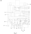
Fig. 1 is a structural diagram of a tab welding device provided by an embodiment of the application; -
Fig. 2 is a right side view of the tab welding device shown inFig. 1 ; -
Fig. 3 is a top view of the tab welding device shown inFig. 1 ; -
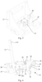
Fig. 4 is a structural diagram of some assemblies in the tab welding device shown inFig. 1 ; -
Fig. 5 is a structural diagram of some assemblies shown inFig. 4 from another direction; -
Fig. 6 is a structural diagram of some assemblies in the tab welding device shown inFig. 1 ; -
Fig. 7 is a structural diagram of some assemblies shown inFig. 6 from another direction; and -
Fig. 8 is a structural diagram of a third connecting plate, a third elastic member and a pressing plate among some assemblies shown inFig. 7 . - In order to make the above objects, features and advantages of this application more obvious and understandable, the following detailed description of this application will be made with reference to the accompanying drawings. In the following description, numerous specific details are set forth in order to provide a thorough understanding of the application. However, this application can be implemented in many other ways different from those described here, and those skilled in the art can make similar improvements without violating the connotation of this application. Therefore, this application is not limited by the specific embodiments disclosed below.
- In the description of the application, it should be understood that directional or positional relationships indicated by the terms such as "center", "longitudinal", "transverse", "length", "width", "thickness", "upper", "lower", "front", "rear", "left", "right", "vertical", "horizontal", "top", "bottom", "inner", "outer", "clockwise", "counterclockwise", "axial", "radial" and "circumferential" are based on the directional or positional relationships shown in the drawings, which are only for the convenience of describing the application and simplifying the description, but do not indicate or imply that the referred devices or elements must have a specific orientation or be constructed and operated in a specific orientation, so they cannot be understood as limiting the application.
- In addition, the terms "first" and "second" are only used for descriptive purposes, and cannot be understood as indicating or implying relative importance or implicitly indicating the number of indicated technical features. Therefore, the features defined with "first" and "second" may include one or more of the features explicitly or implicitly. In the description of this application, "multiple" means at least two, such as two, three, etc., unless otherwise specifically defined.
- In the application, unless otherwise specified and defined, the terms "install", "connect", "attach" and "fix" should be understood in a broad sense. For example, it can be fixed connection, detachable connection or integrated connection; it can be mechanical connection or electric connection; and it can be direct connection, indirect connection through intermediate media or internal communication or interaction of two elements, unless otherwise explicitly defined. For those of ordinary skill in the art, the specific meaning of the above terms in the application can be understood in specific situations.
- In this application, unless otherwise specified and limited, a first feature is "above" or "below" a second feature may mean that the first feature and the second feature are in direct contact, or the first feature and the second feature are in indirect contact through an intermediary. Further, the first feature is "above" the second feature may be that the first feature is directly above or obliquely above the second feature, or it only means that a level of the first feature is higher than that of the second feature; and the first feature is "below" the second feature may be that the first feature is directly below or obliquely below the second feature, or it only means that the level of the first feature is lower than that of the second feature.
- It should be noted that when an element is described as being "fixed to" or "arranged on" another element, it may be directly on another element or there may be an intermediate element. When an element is considered to be "connected" to another element, it may be directly connected with another element or there may be an intermediate element. The terms "vertical", "horizontal", "upper", "lower", "left", "right" and similar expressions used herein are for the purpose of illustration only, and are not meant to be the only implementation way.
- As shown in
Figs. 1 and2 , atab welding device 100 according to an embodiment of the application comprises amounting base 11, awelding assembly 12, a swingingmember 13 and adriving assembly 14. - The
welding assembly 12 is rotatably arranged on themounting base 11, and the swingingmember 13 is connected with thewelding assembly 12. - The
driving assembly 14 is provided with a moving end capable of reciprocating in a first direction, and the moving end is movably connected with the swingingmember 13, and used for driving the swingingmember 13 to swing, so that the swingingmember 13 drives thewelding assembly 12 to rotate. - It should be noted that in this embodiment, the first direction is the left-right direction in
Fig. 1 , and is perpendicular to the principal plane inFig. 2 . - In addition, in this embodiment, the tab welding device is used to weld a tab to an electrode plate.
- By means of the above tab welding device, the driving
assembly 14 drives the swingingmember 13 to swing, and the swingingmember 13 drives thewelding assembly 12 to rotate, so that the angle of thewelding assembly 12 can be adjusted until thewelding assembly 12 is adjusted to an angle allowing a tab to be welded easily. As the angle adjustment of thewelding assembly 12 is realized by the drivingassembly 14, the degree of automation is high, so production efficiency is effectively improved. - In some embodiments, the swinging
member 13 is provided with a slottedhole 131, and the moving end is embedded in the slottedhole 131. And when the moving end drives the swingingmember 13 to swing, the moving end can move in the slottedhole 131. - In some embodiments, the driving
assembly 14 comprises aswing driver 15, a first movingplate 16 and a rollingmember 17, theswing driver 15 is in driving connection with the first movingplate 16 to drive the first movingplate 16 to reciprocate in the first direction, and the rollingmember 17 is rotatably arranged on the first movingplate 16. - It can be understood that the rolling
member 17 is a moving end and embedded in the slottedhole 131. When the rollingmember 17 drives the swingingmember 13 to swing, the rollingmember 17 can move in the slottedhole 131. Because the rollingmember 17 can rotate, the rollingmember 17 rolls in the slottedhole 131. - Further, the driving
assembly 14 further comprises a firstelastic member 18 which is connected between the first movingplate 16 and the swingingmember 13, and used for providing a force to make the rollingmember 17 abut against an inner wall of the slottedhole 131. - The first
elastic member 18 makes the rollingmember 17 abut against the inner wall of the slottedhole 131, thus preventing the rollingmember 17 from swaying in the slottedhole 131 in the swinging process of the swingingmember 13, and further ensuring that the drivingassembly 14 can accurately drive the swingingmember 13 to swing by a certain angle, that is, accurately adjust the rotating angle of thewelding assembly 12. - In practice, the driving
assembly 14 further comprises aguide column 19 which penetrates through the first movingplate 16 and can reciprocate in the first direction. An end of theguide column 19 is connected with the swingingmember 13, and the firstelastic member 18 is connected between theguide column 19 and the first movingplate 16. - Specifically, the first
elastic member 18 is a spring. - In some embodiments, the
swing driver 15 has a driving state and a locked state. - When the
swing driver 15 is in the driving state, theswing driver 15 drives the first movingplate 16 to move, thereby indirectly driving the swingingmember 13 to swing. When theswing driver 15 is in the locked state, theswing driver 15 is self-locked and limits the movement of the first movingplate 16, thus limiting the swing of the swingingmember 13, so as to prevent thewelding assembly 12 from rotating after adjustment is completed, which ensures welding accuracy. - Specifically, the
swing driver 15 is a band-type brake motor or other motors which can realize self-locking. - Referring to
Fig. 3 , in some embodiments, the tab welding device further comprises a liftingassembly 20 which is in driving connection with the mountingbase 11 to drive the mountingbase 11 to reciprocate in a third direction to move close to and away from the electrode plate. - The third direction is the up-down direction in
Fig. 1 , and in practical application, the third direction is a vertical direction. - It should be noted that the lifting
assembly 20 comprises a motor and a screw nut, and the motor is in driving connection with the mountingbase 11 through the screw nut, so as to drive the mountingbase 11 to move vertically. - Referring to
Figs. 4 and5 , in some embodiments, the tab welding device further comprises a first connectingbase 21 and an adjusting assembly, and the adjusting assembly is arranged on the first connectingbase 21 and connected with the mountingbase 11 for adjusting the position of the mountingbase 11 in the first direction and/or the second direction. - The second direction and the first direction are perpendicular to each other, and the second direction is the left-right direction in
Fig. 2 . - In some embodiments, the adjusting assembly comprises a second connecting
base 22 and a first adjustingmember 23, the liftingassembly 20 is in driving connection with the first connectingbase 21, the second connectingbase 22 is arranged on the first connectingbase 21 in a reciprocating manner in the first direction, the mountingbase 11 is arranged on the second connectingbase 22, the first adjustingmember 23 is rotatably arranged on the first connectingbase 21 and connected with the second connectingbase 22, and the first adjustingmember 23 is used for adjusting the position of the second connectingbase 22 in the first direction in the process of rotation. - Further, the first adjusting
member 23 is a screw, and the screw is rotatably arranged on the first connectingbase 21 and in screwed connection with the second connectingbase 22, so as to adjust the positions of the second connectingbase 22 and the mountingbase 11 in the first direction during rotation. - It should be noted that the second connecting
base 22 and the first connectingbase 21 can be connected by a key with a guiding function, so that the second connectingbase 22 can reciprocate in the first direction relative to the first connectingbase 21. - Referring to
Figs. 6 and7 , in some embodiments, the adjusting assembly further comprises a first connectingplate 24, afirst adjusting block 25 and a second adjustingmember 26, the first connectingplate 24 is arranged on the second connectingbase 22, the mountingbase 11 is arranged on the first connectingplate 24 in a reciprocating manner in the second direction, thefirst adjusting block 25 is arranged on the mountingbase 11, the second adjustingmember 26 is rotatably arranged on thefirst adjusting block 25 and connected with the first connectingplate 24, and the second adjustingmember 26 is used for adjusting the position of the mountingbase 11 in the second direction in the process of rotation. - It should be noted that, the second adjusting
member 26 is a screw, and the mountingbase 11 and the first connectingplate 24 can be connected by a key with a guiding function, so that the mountingbase 11 can reciprocate in the second direction relative to the first connectingplate 24. - The first adjusting
member 23 and the second adjustingmember 26 respectively adjust the positions of the second connectingbase 22 and the mountingbase 11 before welding, so as to realize position adjustment of thewelding assembly 12 in the first direction and the second direction, and make thewelding assembly 12 aligned with the tab and the electrode plate, thus ensuring welding accuracy. - In addition, the mounting
base 11 is provided with a scale, which can calibrate the position of the mountingbase 11 when the position of the mountingbase 11 is adjusted in the second direction, thus ensuring adjustment accuracy. - Referring to
Fig. 5 , in some embodiments, the tab welding device further comprises abuffer 27, the first connectingplate 24 is arranged on the second connectingbase 22 in a reciprocating manner in the third direction, thebuffer 27 is arranged between the first connectingplate 24 and the second connectingbase 22, and thebuffer 27 is used for providing a buffer effect for the first connectingplate 24 when the first connectingplate 24 moves in the third direction relative to the second connectingbase 22. - In this way, when the lifting
assembly 20 drives the first connectingbase 21 to move toward the tab, thewelding assembly 12 on the mountingbase 11 will make contact with the tab, and at this point, the first connectingplate 24 will move in the third direction relative to the second connectingbase 22, and thebuffer 27 can provide a buffer effect for the first connectingplate 24 to prevent thewelding assembly 12 from crushing the tab. - In practice, the tab welding device also comprises a
guide rod 28, thebuffer 27 is an air cylinder, theguide rod 28 is connected with the second connectingbase 22 in a reciprocating manner in the third direction, the first connectingplate 24 is connected with theguide rod 28, the air cylinder is arranged on the second connectingbase 22, and a telescopic end of the air cylinder is connected with the first connectingplate 24. - It can be understood that in this embodiment, the air cylinder acts as a gas spring to cushion the movement of the first connecting
plate 24 relative to the second connectingbase 22. - In some embodiments, the tab welding device further comprises a third connecting
base 29, the third connectingbase 29 and the first connectingplate 24 are connected with two ends of theguide rod 28 respectively, and theswing driver 15 is arranged on the third connectingbase 29. - Referring to
Figs. 6 and7 , in some embodiments, the tab welding device further comprises a secondelastic member 30 which is connected between the weldingassembly 12 and the mountingbase 11, and is used to provide a force to make thewelding assembly 12 abut against the mountingbase 11. - It should be noted that, before welding, the
welding assembly 12 needs to be adjusted to be parallel to the tab, this adjustment is fine adjustment, that is, the rotation angle of thewelding assembly 12 is small, so the secondelastic member 30 is used to arrange thewelding assembly 12 on the mountingbase 11, and ensuring that thewelding assembly 12 can rotate. - In practice, the mounting
base 11 is provided with an arc-shaped mounting groove, thewelding assembly 12 is rotatably arranged in the arc-shaped mounting groove around an axis of the arc-shaped mounting groove, and the secondelastic member 30 is used for providing a force to make thewelding assembly 12 abut against the arc-shaped mounting groove. - It can be determined that a surface of the
welding assembly 12 in contact with the mountingbase 11 is arc-shaped, so as to facilitate the rotation of thewelding assembly 12 after being arranged in the arc-shaped mounting groove. - In addition, the axis of the arc-shaped mounting groove is parallel to the second direction.
- In some embodiments, the tab welding device further comprises a second connecting
plate 31, both the swingingmember 13 and thewelding assembly 12 are connected with the second connectingplate 31, and the secondelastic member 30 is connected between the second connectingplate 31 and the mountingbase 11. - It can be understood that the second connecting
plate 31 is connected with thewelding assembly 12, and the second connectingplate 31 can also rotate with thewelding assembly 12, so a gap exists between the second connectingplate 31 and the mountingbase 11 to prevent the mountingbase 11 from interfering with the rotation of the second connectingplate 31. - In some embodiments, the tab welding device further comprises a connecting
column 32 which penetrates through the mountingbase 11 and can reciprocate in the third direction, and the secondelastic member 30 is connected between the mountingbase 11 and the connectingcolumn 32. - It should be noted that the mounting
base 11 is provided with a through hole in the third direction, and the connectingcolumn 32 comprises a connecting section and a connecting head; an end of the connecting section is connected with the second connectingplate 31 and penetrates through the through hole, the connecting section is able to reciprocate in the third direction, and the aperture of the through hole is greater than the diameter of the connecting section; and the connecting head is connected with an end, away from the second connectingplate 31, of the connecting section, and the secondelastic member 30 is connected between the mountingbase 11 and the connecting head. In this way, the connectingcolumn 32 can reciprocate in the third direction, and the connectingcolumn 32 can swing in the through hole, so that thewelding assembly 12 can rotate. - In practice, the second
elastic member 30 is a spring, which is sleeved on the connecting section, and the spring and the second connectingplate 31 are located on two opposite sides of the mountingbase 11 in the third direction respectively, so as to position thewelding assembly 12 in the mounting groove. - It can be understood that the diameter of the connecting head is greater than the radial dimension of the connecting section, so that the connecting head can abut against the second
elastic member 30 sleeved on the connecting section. - In some embodiments, the tab welding device further comprises a limiting assembly, which is arranged on the mounting
base 11 and used for limiting the movement of thewelding assembly 12 in the second direction. - It can be understood that the
welding assembly 12 is arranged in the arc-shaped mounting groove, and the arc-shaped mounting groove does not restrict the rotation of thewelding assembly 12 and movement thereof in the second direction. Therefore, the limiting assembly is arranged on the mountingbase 11 to restrict the movement of thewelding assembly 12 in the second direction and ensure that thewelding assembly 12 will not move relative to the mountingbase 11, thus further ensuring welding accuracy. - In some embodiments, the limiting assembly comprises a first limiting
wheel 33 and a second limitingwheel 34 which are arranged on the mountingbase 11 in a spaced manner in the second direction, the first limitingwheel 33 and the second limitingwheel 34 both are able to rotate, the first limitingwheel 33 and the second limitingwheel 34 both abut against thewelding assembly 12, thewelding assembly 12 can drive the first limitingwheel 33 and the second limitingwheel 34 to rotate during rotation, and the first limitingwheel 33 and the second limitingwheel 34 can limit the movement of thewelding assembly 12 in the second direction. - It should be explained that both the first limiting
wheel 33 and the second limitingwheel 34 abut against thewelding assembly 12, and thewelding assembly 12 can drive the first limitingwheel 33 and the second limitingwheel 34 to rotate when thewelding assembly 12 rotates, that is, the first limitingwheel 33 and the second limitingwheel 34 can roll on a surface of thewelding assembly 12. In this way, the first limitingwheel 33 and the second limitingwheel 34 can not only limit thewelding assembly 12, but also reduce friction and loss because the first limitingwheel 33 and the second limitingwheel 34 roll on the surface of thewelding assembly 12. - In some embodiments, the
welding assembly 12 comprises a claspingmember 35 and awelding head 36. The claspingmember 35 is arranged on the mountingbase 11, the swingingmember 13 is connected with the claspingmember 35, and thewelding head 36 is arranged on the claspingmember 35 and can rotate with the claspingmember 35. - Further, the tab welding device further comprises a locating
member 37 which is arranged on the mountingbase 11, and the claspingmember 35 has an open state and a clasping state. - When the clasping
member 35 is in the open state, thewelding head 36 can reciprocate in the second direction, and thewelding head 36 can abut against the locatingmember 37 in the process of moving in the second direction, so as to be positioned by the locatingmember 37. When the claspingmember 35 is in the clasping state, the claspingmember 35 locks thewelding head 36. - It can be understood that when the clasping
member 35 is in the open state, thewelding head 36 can reciprocate in the second direction, and thewelding head 36 can be replaced at this point. - In practice, the clasping
member 35 is a hold hoop, and there are two hold hoops. The two hold hoops are arranged on the second connectingplate 31 in a spaced manner in the second direction, the two hold hoops respectively abut against two mounting grooves on the mountingbase 11, and the first limitingwheel 33 and the second limitingwheel 34 respectively abut against the two hold hoops. - In some embodiments, the tab welding device further comprises a
second adjusting block 38 which is arranged on the mountingbase 11, the locatingmember 37 is arranged on thesecond adjusting block 38, and the position of the locatingmember 37 is adjustable in the second direction, so that the position of thewelding head 36 can be adjusted to enable the claspingmember 35 to lock different welding heads 36. - In practice, the
second adjusting block 38 is arranged on the first connectingplate 24, and the locatingmember 37 is a positioning screw which is in screwed connection with thesecond adjusting block 38. - In some embodiments, the
welding head 36 comprises a connectingpart 361 and awelding part 362. The connectingpart 361 is connected with the claspingmember 35, and thewelding part 362 is arranged on the connectingpart 361. In this embodiment, thewelding part 362 is used for welding the tab to the electrode plate. - It can be understood that the driving
assembly 14 drives thewelding assembly 12 to rotate through the swingingmember 13 in order to adjust the angle of thewelding part 362, so that thewelding part 362 is parallel to the tab, thus ensuring the welding quality. - Referring to
Figs. 6 to 8 , in some embodiments, the tab welding device further comprises a third connectingplate 39 and apressing plate 40, the third connectingplate 39 is arranged on the second connectingplate 31, thepressing plate 40 is arranged on the third connectingplate 39 in a reciprocating manner in a fourth direction, and thepressing plate 40 is provided with a throughgroove 401. During the movement of thepressing plate 40 in the fourth direction, a welding surface of thewelding part 362 can pass through the throughgroove 401, so as to weld the tab to the electrode plate. - It should be noted that the fourth direction is perpendicular to the axis of the arc-shaped mounting groove, and since the third connecting
plate 39 is arranged on the second connectingplate 31, the fourth direction will change with the rotation of thewelding assembly 12. - Therefore, when the
welding assembly 12 approaches the tab, thepressing plate 40 will make contact with the tab and the electrode plate first, that is, thepressing plate 40 will press against the tab and the electrode plate, and then the welding surface of thewelding part 362 will pass through the throughgroove 401 and weld the tab to the electrode plate. After welding is completed, thewelding part 362 will be separated from the tab and the electrode plate, and then thepressing plate 40 will be separated from the tab and the electrode plate, thus preventing the tab and the electrode plate from sticking to thewelding part 362 to be lifted up. - In practice, the tab welding device further comprises a third
elastic member 41 which is connected between thepressing plate 40 and the third connectingplate 39 and used to provide a force to keep thepressing plate 40 away from the third connectingplate 39, so as to ensure that thepressing plate 40 presses the tab and the electrode plate tightly and the tab and the electrode plate will not be lifted up. - In order to understand the technical scheme of this application, the operation process of the tab welding device in the above embodiment will be described below, and this description assumes that the tab welding device is used to weld a tab to an electrode plate, and the tab is in a horizontal state.
- At the beginning, the clasping
member 35 is in the open state, and the position of the locatingmember 37 is adjusted according to the model of thewelding head 36. Then, thewelding head 36 is inserted into the claspingmember 35 until an end of thewelding head 36 abuts against the locatingmember 37, while ensuring that thewelding part 362 of thewelding head 36 corresponds to the throughgroove 401 in thepressing plate 40. Next, the claspingmember 35 is switched to the clasping state to lock and fix thewelding head 36. - After the
welding head 36 is locked and fixed, the position of thewelding head 36 is adjusted in the first direction and the second direction according to the positions of the tab and the electrode plate. - Specifically, by rotating the first adjusting
member 23, the second connectingbase 22 can move in the first direction relative to the first connectingbase 21, thus adjusting the position of the second connectingbase 22 in the first direction and indirectly adjusting the position of thewelding head 36 in the first direction. By rotating the second adjustingmember 26, the mountingbase 11 can move in the second direction relative to the first connectingplate 24, thereby adjusting the position of the mountingbase 11 in the second direction and indirectly adjusting the position of thewelding head 36 in the second direction. - After the position of the
welding head 36 is adjusted in the first direction and the second direction, theswing driver 15 acts to drive the swingingmember 13 to swing, and the swingingmember 13 drives the second connectingplate 31 and the claspingmember 35 to rotate, thus driving thewelding head 36 to rotate until the welding surface of thewelding part 362 is in a horizontal state. - Finally, the lifting
assembly 20 drives the first connectingbase 21 to move in the third direction, so that thewelding head 36 is close to the tab and the electrode plate. In this process, thepressing plate 40 first presses against the tab and the electrode plate, and then the welding surface of thewelding part 362 passes through the throughgroove 401 to weld the tab to the electrode plate. - After welding, the lifting
assembly 20 drives the first connectingbase 21 to drive thewelding head 36 away from the tab and the electrode plate, and thewelding part 362 is separated from the tab and the electrode plate before thepressing plate 40. - The technical features of the above embodiments can be combined freely. In order to make the description concise, not all possible combinations of the technical features in the above embodiments are described. However, as long as there is no contradiction in the combinations of these technical features, they should be considered as falling within the scope recorded in this specification.
- The above embodiments only represent several implementation ways of the application, and their descriptions are specific and detailed, but they cannot be understood as limiting the scope of the patent of the application. It should be pointed out that, for those of ordinary skill in the art, without departing from the concept of the application, several modifications and improvements can be made, which belong to the protection scope of the application. Therefore, the scope of protection of the patent of the application shall be subject to the appended claims.
Claims (13)
- A tab welding device, comprising:a mounting base;a welding assembly, rotatably arranged on the mounting base;a swinging member, connected with the welding assembly; anda driving assembly, provided with a moving end capable of reciprocating in a first direction, the moving end being movably connected with the swinging member, and being for driving the swinging member to swing to make the swinging member drive the welding assembly to rotate.
- The tab welding device of claim 1, further comprising a first limiting wheel and a second limiting wheel arranged on the mounting base in a spaced mode in a second direction perpendicular to the first direction, the first limiting wheel and the second limiting wheel both being capable of rotating and both abutting against the welding assembly, and the welding assembly, in the process of rotation, being capable of driving the first limiting wheel and the second limiting wheel to rotate.
- The tab welding device of claim 1, wherein the driving assembly comprises a swing driver, a first moving plate and a rolling member, the swing driver is in driving connection with the first moving plate to drive the first moving plate to reciprocate in the first direction, and the rolling member is rotatably arranged on the first moving plate; and
the swinging member is provided with a slotted hole, the rolling member is embedded in the slotted hole and capable of moving in the slotted hole when driving the swinging member to swing. - The tab welding device of claim 3, wherein the driving assembly further comprises a first elastic member connected between the first moving plate and the swinging member, and being for providing a force to make the rolling member abut against an inner wall of the slotted hole.
- The tab welding device of claim 3, wherein the swing driver has a locked state; and
when the swing driver is in the locked state, the swing driver is self-locked and limits the swinging member from swinging. - The tab welding device of any one of claims 1-5, further comprising a first connecting base and an adjusting assembly, and the adjusting assembly being arranged on the first connecting base and connected with the mounting base for adjusting a position of the mounting base in the first direction and/or the second direction;
wherein the first direction and the second direction are perpendicular to each other. - The tab welding device according to claim 6, wherein the adjusting assembly comprises a second connecting base, a first adjusting member, a first connecting plate, a first adjusting block and a second adjusting member, the second connecting base is arranged on the first connecting base in a reciprocating manner in the first direction, the first adjusting member is rotatably arranged on the first connecting base and connected with the second connecting base, and the first adjusting member, in the process of rotation, is for adjusting a position of the second connecting base in the first direction; and
the first connecting plate is arranged on the second connecting base, the mounting base is arranged on the first connecting plate in a reciprocating manner in the second direction, the first adjusting block is arranged on the mounting base, the second adjusting member is rotatably arranged on the first adjusting block and connected with the first connecting plate, and the second adjusting member, in the process of rotation, is for adjusting the position of the mounting base in the second direction. - The tab welding device of claim 7, further comprising a buffer, the first connecting plate being arranged on the second connecting base in a reciprocating manner in a third direction, the buffer being arranged between the first connecting plate and the second connecting base, and the buffer being for providing a buffer effect for the first connecting plate when the first connecting plate moves in the third direction relative to the second connecting base.
- The tab welding device of any one of claims 1-5, wherein the mounting base is provided with an arc-shaped mounting groove, the welding assembly is rotatably arranged in the arc-shaped mounting groove around an axis of the arc-shaped mounting groove, and the tab welding device further comprises a second elastic member connected between the welding assembly and the mounting base for providing a force to make the welding assembly abut against the arc-shaped mounting groove.
- The tab welding device of claim 9, further comprising a second connecting plate and a connecting column, the mounting base being provided with a through hole in the third direction, the connecting column comprising a connecting section and a connecting head, an end of the connecting section being connected with the second connecting plate and penetrating through the through hole, the connecting section being capable of reciprocating in the third direction, an aperture of the through hole being greater than a diameter of the connecting section, the connecting head being connected with an end, away from the second connecting plate, of the connecting section, the second elastic member being connected between the mounting base and the connecting head, and the swinging member and the welding assembly both being connected with the second connecting plate.
- The tab welding device of any one of claims 1-5, wherein the welding assembly comprises a clasping member and a welding head, the clasping member is rotatably arranged on the mounting base, the swinging member is connected with the clasping member, and the welding head is arranged on the clasping member.
- The tab welding device of claim 11, wherein the clasping member has a clasping state and an open state, and the tab welding device further comprises a locating member arranged on the mounting base;when the clasping member is in the clasping state, the clasping member locks the welding head; andwhen the clasping member is in the open state, the welding head is capable of reciprocating in a second direction perpendicular to the first direction, and the welding head, in the process of moving in the second direction, is capable of abutting against the locating member.
- The tab welding device of claim 12, further comprising a second adjusting block arranged on the mounting base, the locating member being arranged on the second adjusting block, and a position of the locating member being adjustable in the second direction.
Applications Claiming Priority (2)
| Application Number | Priority Date | Filing Date | Title |
|---|---|---|---|
| CN202222308824.8U CN218311736U (en) | 2022-08-31 | 2022-08-31 | Welding device |
| PCT/CN2022/129206 WO2024045315A1 (en) | 2022-08-31 | 2022-11-02 | Tab welding device |
Publications (2)
| Publication Number | Publication Date |
|---|---|
| EP4357067A1 true EP4357067A1 (en) | 2024-04-24 |
| EP4357067A4 EP4357067A4 (en) | 2025-07-09 |
Family
ID=90000785
Family Applications (1)
| Application Number | Title | Priority Date | Filing Date |
|---|---|---|---|
| EP22826628.4A Pending EP4357067A4 (en) | 2022-08-31 | 2022-11-02 | Tab welding device |
Country Status (2)
| Country | Link |
|---|---|
| US (1) | US12275097B2 (en) |
| EP (1) | EP4357067A4 (en) |
Families Citing this family (1)
| Publication number | Priority date | Publication date | Assignee | Title |
|---|---|---|---|---|
| CN118455823B (en) * | 2024-07-11 | 2024-09-20 | 四川融成工程技术有限公司 | Electric welding tool equipment for air pipe installation |
Family Cites Families (17)
| Publication number | Priority date | Publication date | Assignee | Title |
|---|---|---|---|---|
| JPS62230478A (en) * | 1986-03-31 | 1987-10-09 | Sumitomo Metal Ind Ltd | Automatic tab plate welding device |
| JP4141401B2 (en) * | 2004-03-26 | 2008-08-27 | 株式会社新川 | Bonding equipment |
| JP4616779B2 (en) * | 2006-03-06 | 2011-01-19 | 株式会社新川 | Horn holder swing type bonding equipment |
| CN201340884Y (en) | 2008-11-28 | 2009-11-04 | 深圳市吉阳自动化科技有限公司 | Fully automatic pole piece bag manufacturing device with power battery core |
| CN101898289A (en) * | 2009-06-01 | 2010-12-01 | 纬泰机械(上海)有限公司 | Welding and positioning device |
| DE102013212331A1 (en) * | 2013-04-04 | 2014-10-09 | Telsonic Holding Ag | Method of connecting a tubular cable lug to a strand made of aluminum |
| US9346120B1 (en) * | 2015-12-28 | 2016-05-24 | Edison Welding Institute, Inc. | Sonotrode apparatus for use in ultrasonic additive manufacturing |
| CN207127393U (en) * | 2017-06-30 | 2018-03-23 | 深圳市炫硕智造技术有限公司 | Lug laser soldering device |
| JP7214991B2 (en) * | 2018-06-28 | 2023-01-31 | Tdk株式会社 | Ultrasonic bonding head, ultrasonic bonding apparatus and ultrasonic bonding method |
| WO2020112635A1 (en) * | 2018-11-28 | 2020-06-04 | Kulicke And Soffa Industries, Inc. | Ultrasonic welding systems and methods of using the same |
| CN210937839U (en) * | 2019-08-27 | 2020-07-07 | 宁德新能源科技有限公司 | Clamping device for tab welding |
| CN110640379A (en) * | 2019-10-28 | 2020-01-03 | 无锡先导智能装备股份有限公司 | A positioning mechanism and a welding auxiliary device |
| EP3908421A1 (en) * | 2019-11-07 | 2021-11-17 | Schunk Sonosystems Gmbh | Ultrasonic welding apparatus with cooling for oscillator arrangement |
| JP7285005B2 (en) * | 2019-11-26 | 2023-06-01 | 株式会社アルテクス | Mechanical vibration processing device and mechanical vibration processing method |
| CN211866934U (en) | 2020-01-08 | 2020-11-06 | 无锡先导智能装备股份有限公司 | Welding auxiliary mechanism and welding device |
| WO2021195926A1 (en) | 2020-03-31 | 2021-10-07 | 宁德新能源科技有限公司 | Battery cell structure and battery |
| CN215145966U (en) * | 2021-04-29 | 2021-12-14 | 惠州亿纬锂能股份有限公司 | Battery tab welding device |
-
2022
- 2022-11-02 EP EP22826628.4A patent/EP4357067A4/en active Pending
- 2022-12-30 US US18/148,602 patent/US12275097B2/en active Active
Also Published As
| Publication number | Publication date |
|---|---|
| US12275097B2 (en) | 2025-04-15 |
| EP4357067A4 (en) | 2025-07-09 |
| US20240066640A1 (en) | 2024-02-29 |
Similar Documents
| Publication | Publication Date | Title |
|---|---|---|
| CN218311736U (en) | Welding device | |
| EP4357067A1 (en) | Tab welding device | |
| US20220278494A1 (en) | Punching head for terminal crimping machine | |
| WO2022179574A1 (en) | Multi-station rotary terminal crimping machine head | |
| CN114749545A (en) | Groove automatic machining auxiliary mechanism based on intelligent machining of elliptical seal head | |
| CN110802352A (en) | Welding device | |
| CN118720357B (en) | A kind of hardware parts welding processing equipment | |
| WO2022179565A1 (en) | Punch head of terminal pressing connection machine | |
| CN113529716A (en) | Positioning base device of hydraulic clamp for overwater steel pile | |
| CN217412788U (en) | Welding head installation mechanism and ultrasonic welding device | |
| CN216095868U (en) | Umbrella frame middle rod punching device | |
| CN213054531U (en) | Combined clamp | |
| CN215470691U (en) | Be applied to automotive fixture's positioning device | |
| CN218311572U (en) | Positioning mechanism and welding device | |
| CN211136088U (en) | Automatic clamping and positioning device | |
| CN213163781U (en) | Welding device with welding pin leveling component | |
| CN212902939U (en) | Buckling size measuring device | |
| CN210160707U (en) | A padlock assembly mechanism | |
| CN222725849U (en) | Clamping device | |
| CN113231773A (en) | Welding head clamping and moving device and automatic welding machine | |
| CN222307799U (en) | Welding device for angle stop block of automobile seat rotating shaft | |
| CN217101914U (en) | High-efficient guide pin upset adjustment mechanism | |
| CN223133607U (en) | A mobile auxiliary disc structure of a winding machine | |
| CN222270953U (en) | Connection structure of oblique kicking block | |
| CN223407003U (en) | A shifting material taking and capping mechanism |
Legal Events
| Date | Code | Title | Description |
|---|---|---|---|
| STAA | Information on the status of an ep patent application or granted ep patent |
Free format text: STATUS: UNKNOWN |
|
| STAA | Information on the status of an ep patent application or granted ep patent |
Free format text: STATUS: THE INTERNATIONAL PUBLICATION HAS BEEN MADE |
|
| PUAI | Public reference made under article 153(3) epc to a published international application that has entered the european phase |
Free format text: ORIGINAL CODE: 0009012 |
|
| STAA | Information on the status of an ep patent application or granted ep patent |
Free format text: STATUS: REQUEST FOR EXAMINATION WAS MADE |
|
| 17P | Request for examination filed |
Effective date: 20221229 |
|
| AK | Designated contracting states |
Kind code of ref document: A1 Designated state(s): AL AT BE BG CH CY CZ DE DK EE ES FI FR GB GR HR HU IE IS IT LI LT LU LV MC ME MK MT NL NO PL PT RO RS SE SI SK SM TR |
|
| A4 | Supplementary search report drawn up and despatched |
Effective date: 20250605 |
|
| RIC1 | Information provided on ipc code assigned before grant |
Ipc: H01M 50/536 20210101ALI20250530BHEP Ipc: B23K 37/04 20060101AFI20250530BHEP |
|
| DAV | Request for validation of the european patent (deleted) | ||
| DAX | Request for extension of the european patent (deleted) | ||
| STAA | Information on the status of an ep patent application or granted ep patent |
Free format text: STATUS: EXAMINATION IS IN PROGRESS |
|
| 17Q | First examination report despatched |
Effective date: 20260112 |