EP4356851B1 - Clip applying mechanism and clip applying apparatus thereof - Google Patents
Clip applying mechanism and clip applying apparatus thereof Download PDFInfo
- Publication number
- EP4356851B1 EP4356851B1 EP23183058.9A EP23183058A EP4356851B1 EP 4356851 B1 EP4356851 B1 EP 4356851B1 EP 23183058 A EP23183058 A EP 23183058A EP 4356851 B1 EP4356851 B1 EP 4356851B1
- Authority
- EP
- European Patent Office
- Prior art keywords
- main
- clip
- connecting member
- shaft connecting
- firing
- Prior art date
- Legal status (The legal status is an assumption and is not a legal conclusion. Google has not performed a legal analysis and makes no representation as to the accuracy of the status listed.)
- Active
Links
Images











Classifications
-
- A—HUMAN NECESSITIES
- A61—MEDICAL OR VETERINARY SCIENCE; HYGIENE
- A61B—DIAGNOSIS; SURGERY; IDENTIFICATION
- A61B17/00—Surgical instruments, devices or methods
- A61B17/12—Surgical instruments, devices or methods for ligaturing or otherwise compressing tubular parts of the body, e.g. blood vessels or umbilical cord
- A61B17/128—Surgical instruments, devices or methods for ligaturing or otherwise compressing tubular parts of the body, e.g. blood vessels or umbilical cord for applying or removing clamps or clips
- A61B17/1285—Surgical instruments, devices or methods for ligaturing or otherwise compressing tubular parts of the body, e.g. blood vessels or umbilical cord for applying or removing clamps or clips for minimally invasive surgery
-
- A—HUMAN NECESSITIES
- A61—MEDICAL OR VETERINARY SCIENCE; HYGIENE
- A61B—DIAGNOSIS; SURGERY; IDENTIFICATION
- A61B17/00—Surgical instruments, devices or methods
- A61B2017/00367—Details of actuation of instruments, e.g. relations between pushing buttons, or the like, and activation of the tool, working tip, or the like
-
- A—HUMAN NECESSITIES
- A61—MEDICAL OR VETERINARY SCIENCE; HYGIENE
- A61B—DIAGNOSIS; SURGERY; IDENTIFICATION
- A61B17/00—Surgical instruments, devices or methods
- A61B2017/0046—Surgical instruments, devices or methods with a releasable handle; with handle and operating part separable
-
- Y—GENERAL TAGGING OF NEW TECHNOLOGICAL DEVELOPMENTS; GENERAL TAGGING OF CROSS-SECTIONAL TECHNOLOGIES SPANNING OVER SEVERAL SECTIONS OF THE IPC; TECHNICAL SUBJECTS COVERED BY FORMER USPC CROSS-REFERENCE ART COLLECTIONS [XRACs] AND DIGESTS
- Y02—TECHNOLOGIES OR APPLICATIONS FOR MITIGATION OR ADAPTATION AGAINST CLIMATE CHANGE
- Y02E—REDUCTION OF GREENHOUSE GAS [GHG] EMISSIONS, RELATED TO ENERGY GENERATION, TRANSMISSION OR DISTRIBUTION
- Y02E30/00—Energy generation of nuclear origin
- Y02E30/30—Nuclear fission reactors
Definitions
- the present disclosure relates to a field of medical devices, and more particularly, to a clip applying mechanism and a clip applying apparatus thereof.
- the clip applying apparatus includes a long rod-shaped clip applying mechanism and a handle assembly.
- the clip applying mechanism may penetrate into a human body via an auxiliary tool, for example, a puncture device.
- the clip applying mechanism may be controlled to convey a ligating clip (briefly referred to as a clip) to an end effector located at the front end of the clip applying mechanism, and then close the end effector to allow the clip to clamp the blood vessel.
- a ligating clip (briefly referred to as a clip)
- US20030014060A1 provides an endoscopic clip applier.
- the clip applier is adapted to retain a plurality of asymmetric ligating clips in a clip channel contained within a shaft assembly, and includes a jaw assembly for applying an asymmetric clip.
- the jaw assembly is connected to the distal end of the clip channel, and a handle assembly is connected to a proximal end of the clip channel.
- a feeder bar is mounted adj acent the clip channel, and is moveable between a proximal position and a distal position to advance clips in the clip applier and to feed a clip from the clip channel to the jaw assembly.
- the shaft assembly is moveable between a proximal position and a distal position, and includes cam surfaces for closing the jaw assembly when the shaft assembly is moved in a distal direction.
- a trigger on the handle assembly actuates the feeder bar to advance clips in the clip channel and advances the shaft assembly to close the jaw assembly.
- US20170128071A1 provides an endoscopic reposable surgical clip appliers having a reusable handle assembly, at least one reusable shaft assembly, and at least one disposable clip cartridge assembly.
- US20190099183A1 discloses a surgical instrument, which comprises an end effector, a shaft, and a housing extending proximally from the shaft.
- the surgical instrument includes an articulation assembly configured to articulate the end effector relative to the shaft, a firing assembly configured to fire a plurality of staples, for example, and a locking member movable between a locked configuration and an unlocked configuration.
- the housing is removably couplable to the shaft when the locking member is in the unlocked configuration and the housing includes a motor configured to drive at least one of the firing assembly and the articulation assembly.
- the housing also includes a controller in communication with the motor, wherein the controller is configured to activate the motor to reset at least one of the firing assembly and the articulation assembly to a home state when the locking member is moved between the locked configuration and the unlocked configuration.
- the clip Before the clip clamps a blood vessel, the clip needs to be conveyed to an end effector located at the front end of a clip applying mechanism, and then the clip is fired through operating a handle assembly.
- the clip In a case where the clip has been conveyed into the end effector, if an operator finds that the clip is not suitable (e.g., a size or a shape of the clip, etc. is not suitable), it is necessary to remove the entire clip applying mechanism from the handle assembly, and then mount another clip applying mechanism with a suitable clip.
- the size of the clip may need to be adjusted at any time, so the replaced clip applying mechanism may be mounted again.
- the present disclosure provide a clip applying mechanism of a clip applying apparatus and the clip applying apparatus including the clip applying mechanism, which at least aims to avoid damaging the end effector when replacing the clip applying mechanism.
- the clip applying mechanism of the clip applying apparatus includes: a tube body, a main shaft, a clip-cartridge assembly, and a clip-pushing assembly.
- the tube body includes a head end and a tail end opposite to each other; the main shaft is arranged proximal to the tail end and at least portion of the main shaft is arranged in the tube body;
- the clip-cartridge assembly is configured to penetrate through the tube body and includes a clip cartridge arranged in the tube body and an end effector being configured to penetrate out of the head end;
- the clip cartridge is configured to be filled with a clip; at least portion of the clip-pushing assembly is arranged in the tube body; and the clip-pushing assembly is configured to be pushed by the main shaft toward the head end to convey the clip in the clip cartridge into the end effector.
- the clip applying mechanism provided by the present disclosure, by providing the main-shaft connecting member connected with the main shaft and providing the locking mechanism between the main-shaft connecting member and the housing, it is ensured that the main-shaft connecting member and the housing are locked through the locking mechanism when the clip is conveyed into the end effector.
- the main-shaft connecting member and the main shaft cannot move in the axial direction of the tube body; and when the clip applying mechanism is used again, a next clip is prevented from being conveyed into the end effector to avoid damage to the end effector, which is favorable for long-term use of the clip applying mechanism.
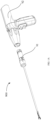
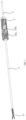
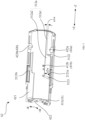
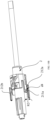
- FIG. 1A and FIG. 1B are respectively schematic diagrams of two states of the clip applying apparatus according to the embodiment of the present disclosure.
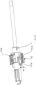
- FIG. 2 is an exploded schematic diagram of the clip applying mechanism according to the embodiment of the present disclosure.
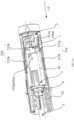
- FIG. 3 is a structural schematic diagram of the clip applying mechanism in an initial state according to the embodiment of the present disclosure.
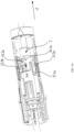
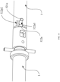
- FIG. 3A is a first partial structural schematic diagram of the clip applying mechanism in the initial state according to the embodiment of the present disclosure.
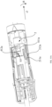
- FIG. 3B is a second partial structural schematic diagram of the clip applying mechanism in the initial state according to the embodiment of the present disclosure.
- FIG. 3C is a third partial structural schematic diagram of the clip applying mechanism in the initial state according to the embodiment of the present disclosure.
- a clip applying apparatus 900 provided by the present disclosure includes a clip applying mechanism 91 and a handle assembly 92.
- the clip applying mechanism 91 is detachably connected with the handle assembly 92.
- an operator may quickly remove the clip applying mechanism 91 from the handle assembly 92 or mount the clip applying mechanism 91 onto the handle assembly 92 according to actual needs.
- the handle assembly 92 is configured to drive the clip applying mechanism 91 to control the clip applying mechanism to execute respective actions, including but not limited to, conveying the clip, firing the clip, resetting the firing assembly, resetting the clip-pushing assembly, and so on.
- the clip applying mechanism 91 includes a tube body 90; and the tube body 90 includes a head end 90A and a tail end 90B opposite to each other. That is, in the axial direction Z of the tube body 90, the head end 90A is opposite to the tail end 90B; the head end 90A is a distal end that is distal to the handle assembly 92 or the operator, and the tail end 90B is a proximal end that is proximal to the handle assembly 92 or the operator.
- an extension direction of the tube body 90 is defined as the axial direction Z, as shown in FIG. 1B ; the axial direction Z includes a +Z direction facing toward the head end 90A and a -Z direction facing away from the head end 90A.
- the axial direction Z includes a +Z direction facing toward the head end 90A and a -Z direction facing away from the head end 90A.
- a circumferential direction of the tube body 90 refers to a direction in which the tube body 90 rotates around a rotation axis 90X thereof, as shown in FIG. 1B ;
- the circumferential direction R includes a first rotation direction +R and a second rotation direction -R opposite to each other.
- first rotation direction +R is counterclockwise
- second rotation direction -R is clockwise.
- the clip applying mechanism 91 includes a main shaft 1, a main-shaft connecting member 2, a firing connecting member 3, a clip-cartridge assembly, a clip-pushing assembly, a firing assembly, a housing 6, a pushing rod 7, and an end cap 12.
- the firing assembly includes, for example, a firing rod 4 and a firing sleeve 5.
- the clip-cartridge assembly includes, for example, a clip cartridge 9 and a clamp 11 (the clamp 11 is also referred to as an end effector).
- the clip-pushing assembly includes, for example, a pushing block 8 and a clip pushing piece 10.
- the tube body 90 has a cavity; and at least portions of the main shaft 1, the clip-cartridge assembly, the clip-pushing assembly, and the firing assembly are arranged in the tube body 90.
- the main shaft 1 is arranged proximal to the tail end 90B of the tube body 90 and at least portion of the main shaft 1 is arranged in the tube body 90.
- the main shaft 1 includes a first end portion 1A and a second end portion 1B opposite to each other; in the axial direction Z, the first end portion 1A is proximal to the head end 90A, and the second end portion 1B is distal to the head end 90A.
- the first end portion 1A is located in the tube body 90.
- the clip-cartridge assembly penetrates through the tube body 90.
- the clip cartridge 9 is arranged in the tube body 90 and is used for loading a plurality of clips.
- the clamp 11 penetrates out of the head end 90A.
- the plurality of clips are arranged in the clip cartridge 9 along the axial direction Z.
- the clip-pushing assembly is arranged in the tube body 90; and the clip-pushing assembly is configured to be pushed by the main shaft 1 toward the head end 90A to convey the clip in the clip cartridge 9 into the clamp 11.
- the pushing block 8 moves in a direction facing toward the head end 90A and drive the clip pushing piece 10 to push the clips in the clip cartridge 9 into the clamp 11 one by one.
- the firing assembly is located in the tube body 90; and the firing assembly is configured to be pushed by the main shaft 1 toward the head end 90A to close the clamp 11, so that the clip in the clamp 11 is fired.
- the firing sleeve 5 is used as the tube body 90, and the clamp 11 penetrates out of a head end of the firing sleeve 5.
- the firing sleeve 5 moves along the +Z direction, the firing sleeve 5 enables two clamp arms of the clamp 11 to move proximal to each other, so that the clamp 11 is in a closed state, and in this situation, the clip is fired.
- the two clamp arms of the clamp 11 move away from each other, so that the clamp 11 in an open state, waiting for subsequent clip convey.
- the main-shaft connecting member 2 is sleeved on the main shaft 1 and connected with the main shaft 1; the main-shaft connecting member 2 is configured to move in a same direction as the main shaft 1 in the axial direction Z.
- the main-shaft connecting member 2 is sleeved on the second end portion 1B of the main shaft 1 and connected with the second end portion 1B; and when the main shaft 1 moves along the +Z or -Z direction, the main-shaft connecting member 2 also moves along the +Z or -Z direction with the main shaft 1.
- the clip applying mechanism 91 further includes an axial engagement mechanism 22, which is arranged between the main shaft 1 and the main-shaft connecting member 2.
- the axial engagement mechanism 22 includes a slot 221 arranged on the main shaft 1 as well as pins 222a, 222b arranged on the main-shaft connecting member 2; and the pins 222a, 222b are configured to move in the slot 221 along the circumferential direction of the main shaft 1.
- the main shaft 1 and the main-shaft connecting member 2 are engaged and connected with each other in the axial direction of the main shaft 1 by using the axial engagement mechanism 22, so that the main shaft 1 and the main-shaft connecting member 2 moves simultaneously in a same direction of the axial direction Z on one hand, and on the other hand, one of the main shaft 1 and the main-shaft connecting member 2 moves relative to the other in the circumferential direction of the main shaft 1, for example, the main shaft 1 and the main-shaft connecting member 2 rotates relative to each other.
- the plurality of pins are arranged at equal interval in the circumferential direction of the main shaft 1, rendering a uniform force on the main shaft 1 or the main-shaft connecting member 2, thereby avoiding damage to the main shaft 1 or the main-shaft connecting member 2 caused by the clip applying mechanism during operation.
- the two pins 222a and 222b are arranged symmetrically in a radial direction of the main shaft 1, which reduces the number of pins as much as possible, save fabrication costs, and reduce manufacturing difficulty, under the condition of ensuring a uniform force on the main shaft 1 or the main-shaft connecting member 2.
- the main shaft 1 and the tube body 90 are arranged parallel to each other, so the axial direction Z of the tube body 90 may be referred to for the axial direction of the main shaft 1, the circumferential direction R of the tube body 90 may be referred to for the circumferential direction of the main shaft 1, and a radial direction P of the tube body 90 shown in FIG. 3D may be referred to for the radial direction of the main shaft 1.
- the main-shaft connecting member 2 is located between the main shaft 1 and the housing 6 in the radial direction P of the main shaft 1.
- the housing 6 includes a first housing portion 61 and a second housing portion 62 connected with the first housing portion 61 in the axial direction Z; the first housing portion 61 is proximal to the head end 90A; and the second housing portion 62 is distal to the head end 90A.
- the first housing portion 61 is configured to be capable of rotating in the circumferential direction R relative to the second housing portion 62.
- the first housing portion 61 is fixedly connected with the clip-pushing assembly and the firing assembly, and the operator may adjust a rotation angle of the clip feeding assembly and the firing assembly by rotating the first housing portion 61.
- the second housing portion 62 keeps fixed relative to the main-shaft connecting member 2, which is favorable for implementing locking between the second housing portion 62 and the main-shaft connecting member 2.
- locking mechanisms 21a, 21b are arranged between the main-shaft connecting member 2 and the housing 6.
- the locking mechanisms 21a, 21b are arranged between the main-shaft connecting member 2 and the second housing portion 62.
- the main-shaft connecting member 2 and the second housing portion 62 are locked with each other through the locking mechanisms 21a, 21b. That is, in the axial direction Z and the circumferential direction R, the main-shaft connecting member 2 and the second housing portion 62 keep fixed to each other, so that the main shaft 1 and the main-shaft connecting member 2 cannot move in the Z direction.
- the locking mechanisms 21a, 21b include first locking members 211a, 211b arranged on the main-shaft connecting member 2 and second locking members 212a, 212b arranged on the housing 6.
- the locking mechanism 21a includes a first locking member 211a arranged on the main-shaft connecting member 2 and a second locking member 212a arranged on the second housing portion 62;
- the locking mechanism 21b includes a first locking member 211b arranged on the main-shaft connecting member 2 and a second locking member 212b arranged on the second housing portion 62.
- the first locking member 211a and the second locking member 212a are configured such that: when the main shaft 1 and the main-shaft connecting member 2 move along the +Z direction to push the clip-pushing assembly to convey the clip into the clamp 11, the first locking member 211a and the second locking member 212a are locked with each other, and the first locking member 211b and the second locking member 212b are locked with each other.
- the main shaft 1 and the main-shaft connecting member 2 keep fixed in the axial direction Z of the tube body 90 relative to the housing 6 when the clip is conveyed into the clamp 11, which, on one hand, prevents the main shaft 1 from driving the clip-pushing assembly to continue to convey the clip to the clamp 11, on the other hand, avoids accidental situations such as error firing due to movement of the main shaft 1 or the main-shaft connecting member during the removing process, thereby increasing safety of operation.
- the main shaft 1 includes the first end portion 1A and the second end portion 1B opposite to each other; in the axial direction Z of the tube body 90, the first end portion 1A is proximal to the head end 90A, and the second end portion 1B is distal to the head end 90A.
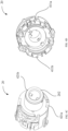
- FIG. 4A is a first structural schematic diagram of the main-shaft connecting member according to the embodiment of the present disclosure
- FIG. 4B shows a partial structural schematic diagram of the main-shaft connecting member according to the embodiment of the present disclosure
- FIG. 4C is a second structural schematic diagram of the main-shaft connecting member according to the embodiment of the present disclosure
- FIG. 4D is a third structural schematic diagram of the main-shaft connecting member according to the embodiment of the present disclosure.
- the main-shaft connecting member 2 is a tubular member 20, and at least portion of the tubular member 20 is sleeved on the second end portion 1B of the main shaft 1.
- the tubular member 20 has a cavity, the main shaft 1 is arranged in the cavity, and the axial engagement mechanism 22 is arranged in the tubular member 20, so that the main shaft 1 and the main-shaft connecting member 2 are engaged with each other in the Z direction.
- the tubular member 20 i.e., the main-shaft connecting member 2 is arranged parallel to the tube body 90, so the axial direction Z of the tube body 90 may be referred to for the extension direction or the axial direction of the tubular member 20; the circumferential direction R of the tube body 90 may be referred to for the circumferential direction of the tubular member 20; and the radial direction P of the tube body 90 may be referred to for the radial direction of the tubular member 20.
- the tubular member 20 includes a tube wall 203; and the tube wall 203 defines a cavity of the tubular member 20.
- the tube wall 203 includes a first end face 201 and a second end face 202 opposite to each other in the extension direction of the tubular member 20; the first end face 201 is proximal to the head end 90A, and the second end face 202 is distal to the head end 90A.
- the first locking member 211a includes a protruding portion 2112a extending from the first end face 201 of the tube wall 203 toward the head end 90A and a first hook 2111a arranged on the protruding portion 2112a;
- the first locking member 211b includes a protruding portion 2112b extending from the first end face 201 of the tube wall 203 toward the head end 90A and a first hook 2111b arranged on the protruding portion 2112b.
- the housing 6 includes an inner wall facing toward the main-shaft connecting member 2; the second locking member includes a second hook arranged on the inner wall; and the first hook and the second hook are configured to be engaged with each other.
- FIG. 5 is a partial structural schematic diagram of the second housing portion according to the embodiment of the present disclosure.
- the second housing portion 62 is substantially cylindrical and includes an inner wall 621 facing toward the main-shaft connecting member 2.
- the second locking member 212a includes a second hook 2121a arranged on the inner wall 621; and the second locking member 212b includes a second hook 2121b arranged on the inner wall 621.
- the first hook 2111a and the second hook 2121a are configured to be engaged with each other; and the first hook 2111b and the second hook 2121b are configured to be engaged with each other.
- the first hooks 2111a, 2111b are arranged on the protruding portions 2112a, 2112b extending from the first end face 201, which is more favorable during the rebound of the protruding portions 2112a, 2112b in the radial direction of the tubular member 20, so that the first hooks 2111a, 2111b are more easily engaged with the second hooks 2121a, 2121b.
- the first hook 2111a is taken as an example. If the first hook 2111a is directly arranged on the first end face 201 (rather than being arranged on the protruding portion 2112a), in a case where the first hook 2111a and the second hook 2121a in FIG. 3B are to be engaged with each other, a great force is required to push the main-shaft connecting member 2 so that the first hook 2111a and the second hook 2121a are engaged with each other, because the first hook 2111a has no rebound space.
- the protruding portion 2112a is extend from the first end face of the tube wall 203, the protruding portion 2112a is no longer limited by the tube wall 203 and has certain rebound space, thereby reducing resistance force when the first hook 2111a and the second hook 2121a are engaged with each other.
- FIG. 4B shows positional relationships among the first end face 201, the first hook 2111a and the protruding portion 2112a of the tube wall 203.
- a distance between a terminal end of the protruding portion 2112a and the first end face 201 in the Z direction is defined as D
- a total length of the tubular member 20 in the Z direction thereof is defined as L (not shown), where L is 4 to 12 times of D.
- the tubular member 20 further includes two through slots 2031, 2032 arranged in the tube wall 203.
- the two through slots 2031, 2032 extend substantially along the Z direction, so an extension direction of the two through slots 2031, 2032 is parallel to the Z direction.
- the two through slots 2031, 2032 may have a same shape or different shapes.
- the fabrication process may be simplified, which, thus, is preferred.
- the embodiments of the present disclosure are illustrated by taking that the two have the same shape as an example.
- the through slot 2031 includes a notch 2031o provided on the first end face 201.
- the notch 2031o is connected with the protruding portion 2112a, that is, in the circumferential direction of the tubular member 20, the notch 2031o and the protruding portion 2112a are adjacent to each other.
- the protruding portion 2112a moves in the radial direction P of the tubular member 20 (i.e., rebound occurs).
- a movement range or rebound space of the protruding portion 2112a is increased, thereby further reducing resistance force when the first hook 2111a and the second hook 2121a are engaged with each other.
- the two through slots 2031, 2032 are respectively arranged on two opposite sides of the protruding portion 2112a, so that the two notches of the two through slots 2031, 2032 are respectively arranged on two opposite sides of the protruding portion 2112a and are adjacent to the protruding portion 2112a.
- the protruding portion 2112b is also provided with two through slots on two opposite sides of the protruding portion 2112b in the circumferential direction of the tubular member 20, and no details will be repeated here.
- the clip applying mechanism 91 further includes a reset member for resetting the clip applying mechanism 91, for example, the reset member is arranged in the housing.
- the clip applying mechanism 91 includes a first spring 13a (i.e., a first reset member) arranged in the first housing portion 61 and a second spring 13b (i.e., a second reset member) arranged in the second housing portion 62.
- the first spring 13a is sleeved on the firing rod 4, abuts between the first housing portion 61 and the firing rod 4, and is used for resetting the firing assembly.
- the second spring 13b is sleeved on the firing connecting member 3, abuts between the second housing portion 62 and the main-shaft connecting member 2, and is used for resetting the clip-pushing assembly, the main shaft 1 and the main-shaft connecting member 2.
- the main-shaft connecting member 2 is provided therein with a step portion 204, and the second spring 13b abuts between an inner surface of the second housing portion 62 and the step portion 204 of the main-shaft connecting member 2.
- the clip applying mechanism 91 executes respective actions, the clip applying mechanism has a plurality of different operation states.
- the clip applying mechanism 91 according to the embodiment of the present disclosure is set to have states below:
- the term "external force” refers to a force not generated by a component per se, which may refer to a force from outside the clip applying mechanism (e.g., a driving force provided by the handle assembly or a force directly applied to the clip applying mechanism by the operator), or may also refer to a force generated by other component in the clip applying mechanism.
- the force may be a pushing force from the pushing rod 7, or may also be a driving force generated due to movement of the main shaft 1, or may also be a reset force generated by the reset member.
- the adjustment state C is an optional state. That is, the clip applying mechanism 91 may or may not have the adjustment state C. In some cases, whether the clip applying mechanism 91 has an adjustment state may be determined according to a rebound performance of the clip.
- the clip applying mechanism 91 may have the above-described adjustment state C.
- a width of the clip in the clamp 11 is larger than a diameter of a puncture device (the puncture device is, for example, a circular tube having a diameter)
- the open-close angle of the clamp 11 is reduced through the adjustment state C, thereby reducing the width of the clip and making it easier for the clip applying mechanism 91 to pass through the puncture device.
- the clip in the clamp 11 is a plastic clip with a width of about 17.5 mm, and the diameter of the puncture device is approximately 10 mm.
- the width of the clip is reduced from 17.5 mm to about 10 mm, so that the clamp 11 of the clip applying mechanism 91 smoothly passes through the puncture device.
- the clip applying mechanism 91 may not have the above-described adjustment state C.
- the clip is a metal clip with low elasticity; if the open-close angle of the clamp 11 is reduced, the metal clip cannot rebound, resulting in that the metal clip cannot be used normally.
- a width of the metal clip is approximately 5.6 mm, with this width, the clip is ensured to pass through the puncture device smoothly, there is no need to adjust the open-close angle of the clamp 11.
- the embodiment of the present disclosure is illustrated by taking that the clip applying mechanism 91 has the adjustment state C as an example.
- the clip applying mechanism 91 in FIG. 3 to FIG. 3D is in the initial state A.
- FIG. 6 is a partial structural schematic diagram of the clip applying mechanism in the clip feeding completion state B according to the embodiment of the present disclosure.
- FIG. 7A is a first partial structural schematic diagram of the clip applying mechanism in the adjustment state C according to the embodiment of the present disclosure.
- FIG. 7B is a second partial structural schematic diagram of the clip applying mechanism in the adjustment state C according to the embodiment of the present disclosure.
- FIG. 7C is a third partial structural schematic diagram of the clip applying mechanism in the adjustment state C according to the embodiment of the present disclosure.
- FIG. 8A is a first structural schematic diagram of the clip applying mechanism in the firing completion state D according to the embodiment of the present disclosure.
- FIG. 8B is a second structural schematic diagram of the clip applying mechanism in the firing completion state D according to the embodiment of the present disclosure.
- FIG. 8C is a third structural schematic diagram of the clip applying mechanism in the firing completion state D according to the embodiment of the present disclosure.
- FIG. 9A is a first structural schematic diagram of the clip applying mechanism in the retreat state E according to the embodiment of the present disclosure.
- FIG. 9B is a second structural schematic diagram of the clip applying mechanism in the retreat state E according to the embodiment of the present disclosure.
- FIG. 9C is a third structural schematic diagram of the clip applying mechanism in the retreat state E according to the embodiment of the present disclosure.
- the main-shaft connecting member 2 is also set to have the initial state A, the clip feeding completion state B, the adjustment state C, the firing completion state D, the retreat state E, the gyration state F, and the returning to the initial state G below, to indicate that it is synchronized with the above-described seven states of the clip applying mechanism.
- the clip applying mechanism is in the initial state A
- the main shaft 1 and the main-shaft connecting member 2 are not applied with an external force
- the main-shaft connecting member 2 is in the initial state A
- the locking mechanisms 21a, 21b are in initial positions.
- the first locking member 211a and the second locking member 212a are separated from each other in the Z direction, and the first locking member 211a is further away from the head end 90A than the second locking member 212a; the first locking member 211b and the second locking member 212b are separated from each other in the Z direction and the first locking member 211b is further away from the head end 90A than the second locking member 212b.
- the main-shaft connecting member 2 switches from the initial state A to the clip feeding completion state B, and the locking mechanisms 21a, 21b change from the initial positions to lock positions.
- the first locking member 211a and the second locking member 212a are locked with each other, and the first locking member 211b and the second locking member 212b are locked with each other.
- the above-described switching process from the initial state A to the clip feeding completion state B is implemented in a mode below: As shown in FIG. 3A and FIG. 6 , applying an external force, so that the main shaft 1 and the main-shaft connecting member 2 move along the +Z direction. During the moving process, the main shaft 1 pushes the clip-pushing assembly so that the clip is conveyed into the clamp 11; and the main-shaft connecting member 2 drives the first locking members 211a, 211b to move together along the +Z direction to respectively be locked with the second locking members 212a, 212b.
- a circumferential distance along the R direction between the first locking member 211a and the second locking member 212a in the lock state is defined as zero, and an included angle along the R direction between the first locking member 211a and the second locking member 212a in the lock state is defined as zero.
- a definition mode of the first locking member 211b and the second locking member 212b is the same as the above mode, and no details will be repeated here.
- the main-shaft connecting member 2 switches from the clip feeding completion state B to the adjustment state C, and the locking mechanisms 21a, 21b change from the lock positions to first unlock positions.
- the first unlock positions the first locking member 211a and the second locking member 212a are separated from each other by a first distance d1 in the Z direction; the first locking member 211b and the second locking member 212b are separated from each other by a first distance d1 in the Z direction.
- the above-described switching process from the clip feeding completion state B to the adjustment state C is implemented in a mode below: Continuing to apply an external force, so that the main shaft 1 and the main-shaft connecting member 2 continue to move in the +Z direction.
- the main shaft 1 transfers the external force to the firing sleeve 5, so that the firing sleeve 5 moves along the +Z direction; movement of the firing sleeve 5 enables the two clamp arms of the clamp 11 to move proximal to each other, to reduce an included angle between the two clamp arms, so as to achieve the purpose of adjusting the open-close angle of the clamp 11.
- the main-shaft connecting member 2 drives the first locking members 211a, 211b to continue to move along the +Z direction, so as to increase the distance between the first locking members 211a, 211b and the second locking members 212a, 212b in the Z direction up to the first distance d1, as shown in FIG. 7A .
- the above-described adjustment of the clamp 11 is particularly applicable to a case where the clip applying mechanism 91 penetrates through a narrower puncture device, which can protect the clamp 11 from being damaged by bumping when penetrating through the puncture device.
- the first locking member 211a and the second locking member 212a are separated from each other by a second distance d2 in the Z direction and the two are separated from each other by a first circumferential distance R1 in the circumferential direction R; the first locking member 211b and the second locking member 212b are separated from each other by a second distance d2 in the Z direction and the two are separated from each other by a first circumferential distance R1 in the circumferential direction R.
- the second distance d2 is greater than the first distance d1
- the first circumferential distance R1 is greater than zero.
- the above-described switching process from the adjustment state C to the firing completion state D is implemented in a mode below: Continuing to apply an external force, so that the main shaft 1 and the main-shaft connecting member 2 continue to move along the +Z direction, and the main-shaft connecting member 2 rotates along the first rotation direction +R.
- the main shaft 1 pushes the firing sleeve 5 to continue to move along the +Z direction, so that the clamp 11 is closed, thereby firing the clip.
- the main-shaft connecting member 2 drives the first locking members 211a, 211b to continue to move along the +Z direction to increase the first distance d1 up to the second distance d2, as shown in FIG. 8A .
- the main-shaft connecting member 2 also drives the first locking members 211a, 211b to rotate a certain angle along the first rotation direction +R (for example, the angle a1 is approximately 32°) to increase the distance between the first locking member 211a and the second locking member 212a in the circumferential direction R up to the first circumferential distance R1, and to increase the distance between the first locking member 211b and the second locking member 212b in the circumferential direction R up to the first circumferential distance R1.
- the first locking member 211a and the second locking member 212a are staggered by a rotation angle
- the first locking member 211b and the second locking member 212b are also staggered by the same rotation angle.
- the circumferential distance between the first locking member and the second locking member when they are locked with each other is set to zero, so the first circumferential distance R1 is greater than zero.
- the first locking member is driven to rotate relative to the second locking member and the two are staggered from each other in the circumferential direction, in this way, in a case that the firing assembly retreats in the -Z direction to reset, the first locking member and the second locking member are effectively prevented from colliding with each other, so as to prevent the reset process of the firing assembly from being obstructed.
- the main-shaft connecting member 2 and the main shaft 1 are at a farthest distance from the handle assembly 91.
- the distance between the first locking member 211a and the second locking member 212a in the Z direction and the distance between the first locking member 211b and the second locking member 212b in the Z direction reach maximum values.
- the first locking member 211a and the second locking member 212a are separated from each other by a third distance d3 in the Z direction, and the two keep spaced from each other by the first circumferential distance R1 in the R direction; the first locking member 211b and the second locking member 212b are separated from each other by the third distance d3 in the Z direction, and the two keep separated from each other by the first circumferential distance R1 in the R direction.
- the third distance d3 is less than the second distance d2 and greater than zero.
- the above-described switching process from the firing completion state D to the retreat state E is implemented in a mode below: Applying an external force, so that the main shaft 1 and the main-shaft connecting member 2 move along the -Z direction.
- the main-shaft connecting member 2 drives the firing connecting member 3 to move along the -Z direction
- the firing connecting member 3 drives the firing rod 4 to move along the -Z direction
- the firing rod 4 drives the firing sleeve 5 to move along the -Z direction, that is, the firing sleeve 5 retreats a certain distance. While the firing sleeve 5 retreats, the two clamp arms of the clamp 11 move away from each other, and the included angle between the two clamp arms gradually increases.
- the main-shaft connecting member 2 also drives the first locking members 211a, 211b to move along the -Z direction, so that the distance between the first locking member 211a and the second locking member 212a in the Z direction decreases from the second distance d2 to the third distance d3, and the distance between the first locking member 211b and the second locking member 212b in the Z direction decreases from the second distance d2 to the third distance d3.
- the firing sleeve 5 is possibly stuck at the clamp 11, and it is difficult to make the firing sleeve 5 retreat (i.e. move along the -Z direction) only by virtue of the reset force of the first spring 13a.
- the external force applied to the main-shaft connecting member 2 is finally transferred to the firing sleeve 5, so that the firing sleeve 5 is forced to retreat a certain distance (because the main-shaft connecting member 2 drives the firing connecting member 3 to move, the firing connecting member 3 drives the firing rod 4 to move, and the firing rod 4 drives the firing sleeve 5 to move), thereby avoiding the problem that the firing sleeve 5 cannot be reset because it is stuck.
- the first locking member 211a and the second locking member 212a are separated from each other by a fourth distance d4 in the Z direction and the two are separated from each other by a second circumferential distance R2 in the R direction; the first locking member 211b and the second locking member 212b are separated from each other by the fourth distance d4 in the Z direction and the two are separated from each other by the second circumferential distance R2 in the R direction.
- the fourth distance d4 is less than the third distance d3, the second circumferential distance R2 is less than the first circumferential distance R1 and greater than zero.
- the fourth distance d4 is equal to zero.
- the above-described switching process from the retreat state E to the gyration state F is in a mode below: Under an action of the reset force of the first spring 13a, the main shaft 1 and the main-shaft connecting member 2 move along the -Z direction, and simultaneously the main-shaft connecting member 2 gyrates along the second rotation direction -R.
- the main-shaft connecting member 2 drives the first locking members 211a, 211b to move along the -Z direction, so that the distance between the first locking member 211a and the second locking member 212a in the Z direction decreases from the third distance d3 to the fourth distance d4, and the distance between the first locking member 211b and the second locking member 212b in the Z direction decreases from the third distance d3 to the fourth distance d4, as shown in FIG. 10B .
- the main-shaft connecting member 2 also drives the first locking members 211a, 211b to gyrate by an angle a2 along the second rotation direction -R, so as to reduce the first circumferential distance R1 to the second circumferential distance R2.
- the second rotation direction -R is opposite to the first rotation direction +R.
- the second circumferential distance R2 is less than the first circumferential distance R1.
- the angle a2 is less than the angle a1 and greater than zero, so that the first locking member and the second locking member still remain staggered from each other in the circumferential direction in the gyration state, so as to prevent the first locking member and the second locking member from colliding with each other in a case where the locking mechanism returns to the initial position.
- the angle a2 is 1/2 to 1/3 of the angle a1.
- the angle a1 is approximately 32° and the angle a2 is approximately 16°.
- a distance between the first hook of the first locking member and the second hook of the second locking member in the Z direction is defined as the distance between the first locking member and the second locking member in the Z direction; for example, in a case where the locking mechanism is in a lock state, if a distance between the first hook 2111a and the second hook 2121a in FIG. 3B in the Z direction is zero, then the distance between the first locking member 211a and the second locking member 212a in FIG. 6 in the Z direction is also zero. As shown in FIG. 7B , FIG. 8B , FIG. 9B and FIG.
- the distance between the first hook 2111a and the second hook 2121a in the Z direction is respectively d1, d2, d3 or d4
- the distance between the first locking member 211a and the second locking member 212a in the Z direction is also d1, d2, d3 or d4. It may be seen from FIG. 7B , FIG. 8B , FIG. 9B and FIG. 10B that in the Z direction, the first hook 2111a is more proximal to the head end 90A than the second hook 2121a.
- the fourth distance d4 is equal to zero.
- the above-described switching process from the gyration state F to the initial state A is in a mode below: Under an action of the reset force of the second spring 13b, the main shaft 1 and the main-shaft connecting member 2 continue to move along the -Z direction, and at the same time, the main-shaft connecting member 2 continues to rotate along the second rotation direction -R until the main-shaft connecting member 2 returns to the initial position.
- the main-shaft connecting member 2 drives the first locking members 211a, 211b to continue moving along the -Z direction, so that the first locking members 211a, 211b move to a side of the second locking members 212a, 212b that is distal to the head end 90A, so as to enable the locking mechanisms 21a, 21b to return to the initial positions.
- the first hook 2111a is more proximal to the head end 90A than the second hook 2121a in FIG. 7B , FIG. 8B , FIG. 9B and FIG. 10B
- the first locking members 211a, 211b are located on the side of the second locking members 212a, 212b that is distal to the head end 90A.
- the main-shaft connecting member 2 also drives the first locking members 211a, 211b to continue to rotate by an angle a3 along the second rotation direction -R to reduce the second circumferential distance R2 to zero.
- the first locking member and the second locking member both gyrate to the initial positions.
- the angle a3 is approximately 16°.
- the plurality of locking mechanisms are arranged between the main-shaft connecting member 2 and the housing 6 along the circumferential direction of the main-shaft connecting member 2 at equal interval, so that the force endured by the main-shaft connecting member 2 or the housing 6 is uniform and an effect of locking in place is increased.
- the main-shaft connecting member 2 is a tubular member 20, and the two locking mechanisms 21a, 21b are symmetrically arranged in the radial direction of the tubular member 20; in this way, the total number of locking mechanisms is reduced as much as possible, the fabrication costs is saved, and the manufacturing difficulty is reduced, under the condition of ensuring a uniform force endured by the main-shaft connecting member 2 or the housing 6.
- the present disclosure provides a clip applying mechanism of a clip applying apparatus, which at least aims to be capable of forcibly pulling the firing sleeve back a certain distance after the clip is fired, so as to assist in reset of the firing sleeve.
- the clip applying mechanism of the clip applying apparatus includes: a tube body, a main shaft, a clip-cartridge assembly, a clip-pushing assembly and a firing assembly.
- the tube body includes a head end and a tail end opposite to each other; the main shaft is arranged proximal to the tail end and at least portion of the main shaft is arranged in the tube body;
- the clip-cartridge assembly penetrates through the tube body and includes: a clip cartridge arranged in the tube body and an end effector configured to penetrate out of the head end, the clip cartridge is configured to be filled with a clip; at least portion of the clip-pushing assembly is arranged in the tube body, the clip-pushing assembly is configured to be pushed by the main shaft toward the head end to convey the clip in the clip cartridge into the end effector; at least portion of the firing assembly is located in the tube body, and the firing assembly is configured to be pushed by the main shaft toward the head end to close the end effector, so that the clip within the end effector is fired.
- the clip applying mechanism further includes: a main-shaft connecting member, a firing connecting member and an engagement mechanism.
- the main-shaft connecting member is connected with the main shaft; the firing connecting member is connected with the firing assembly; the engagement mechanism is arranged between the main-shaft connecting member and the firing connecting member.
- the engagement mechanism, the firing connecting member, the main-shaft connecting member and the firing assembly are configured such that: in a case where the clip is fired, the main-shaft connecting member drives the firing connecting member to move away from the head end through the engagement mechanism, and the firing connecting member drives the firing assembly to move in a same direction, so that the end effector is partially opened.
- the firing assembly is pulled back in a direction facing away from the head end by using the main-shaft connecting member, the engagement mechanism and the firing connecting member, thereby facilitating reset of the firing sleeve and avoiding impact on subsequent actions.
- a clip applying apparatus 900 provided by the present disclosure includes a clip applying mechanism 91 and a handle assembly 92.
- the clip applying mechanism 91 is detachably connected with the handle assembly 92.
- the clip applying mechanism 91 includes a tube body 90, a main shaft 1, a main-shaft connecting member 2, a firing connecting member 3, a clip-cartridge assembly, a clip-pushing assembly, a firing assembly, a housing 6, a pushing rod 7, and an end cap 12.
- the firing assembly includes, for example, a firing rod 4 and a firing sleeve 5.
- the clip-cartridge assembly includes, for example, a clip cartridge 9 and a clamp 11 (also referred to as an end effector).
- the clip-pushing assembly includes, for example, a pushing block 8 and a clip pushing piece 10.
- the tube body 90 includes a head end 90A and a tail end 90B opposite to each other.
- the main shaft 1 is arranged proximal to the tail end 90B and at least portion of the main shaft 1 is located in the tube body 90.
- the clip-cartridge assembly penetrates through the tube body 90, and the clip-cartridge assembly includes a clip cartridge arranged in the tube body 90 and a clamp 11 penetrating out of the head end 90A.
- the clip cartridge is configured to be filled with a clip.
- At least portion of the clip-pushing assembly is arranged in the tube body 90, and the clip-pushing assembly is configured to be pushed by the main shaft 1 toward the head end 90A to convey the clip in the clip cartridge into the clamp 11.
- At least portion of the firing assembly is located in the tube body 90, and the firing assembly is configured to be pushed by the main shaft 1 toward the head end 90A to close the clamp 11, so that the clip in the clamp 11 is fired.
- the clip applying mechanism 91 further includes engagement mechanisms 31a, 31b arranged between the main-shaft connecting member 2 and the firing connecting member 3.
- the main-shaft connecting member 2 drives the firing connecting member 3 to move along the -Z direction through the engagement mechanisms 31a, 31b, and the firing connecting member 3 drives the firing assembly to move in a same direction, so that the clamp 11 is partially opened.
- the main-shaft connecting member 2 is connected with the main shaft 1 through an axial engagement mechanism 22.
- the firing assembly includes a firing sleeve 5 and a firing rod 4 at least partially located in the firing sleeve 5.
- the firing sleeve 5 is used as the tube body 90 and connected with the firing rod 4, so that in a case where the firing rod 4 moves in the Z direction, the firing sleeve 5 also moves in the Z direction.
- the firing rod 4 moves along the -Z direction
- it drives the firing sleeve 5 to retreat along the -Z direction, so that the clamp 11 is partially opened.
- the firing rod 4 is connected with the firing connecting member 3, so that in a case where the firing connecting member 3 moves in the Z direction, the firing rod 4 also moves in the Z direction.
- the firing connecting member 3 moves along the -Z direction, it drives the firing rod 4 to retreat along the -Z direction.
- the firing rod 4 includes a first rod-shaped portion 4A and a second rod-shaped portion 4B in an extension direction of the firing rod 4; the first rod-shaped portion 4A is proximal to the head end 90A, and the second rod-shaped portion 4B is distal to the head end 90A.
- the firing sleeve 5 is sleeved on and connected with the first rod-shaped portion 4A, and the firing connecting member 3 is sleeved on and connected with the second rod-shaped portion 4B.
- the term "rod” or “rod-shaped portion” represents an elongated shape, which does not mean that the rod or the rod-shaped portion is a solid structure.
- the firing rod 4 is hollow to form a cavity that is capable of accommodating the main shaft 1.
- the engagement mechanism 31a includes a pin 311a (i.e., a first engagement member) arranged on the main-shaft connecting member 2 and a slot 312a (i.e., a second engagement member) arranged on the firing connecting member 3;
- the engagement mechanism 31b includes a pin 311b (i.e., a first engagement member) arranged on the main-shaft connecting member 2 and a slot 312b (i.e., a second engagement member) arranged on the firing connecting member 3.
- the engagement mechanisms 31a, 31b have a separate state, a release state, and a lock state.
- the pin 311a and the slot 312a are separated from each other, and the pin 311a is located outside the slot 312a; the pin 311b and the slot 312b are separated from each other, and the pin 311b is located outside the slot 312b.
- the engagement mechanisms 31a, 31b are in the separate state.
- the pins 311a, 311b are respectively located in the slots 312a, 312b and are capable of moving out of the slots 312a, 312b.
- the engagement mechanisms 31a, 31b are in the release state.
- the pins 311a, 311b are respectively locked with the slots 312a, 312b.
- relative positions of the main-shaft connecting member 2 and the firing connecting member 3 both remain fixed in the Z direction or the R direction, so the main-shaft connecting member 2 can drive the firing connecting member 3 to move in the Z direction.
- the engagement mechanisms 31a, 31b are in the lock state.
- the engagement mechanisms 31a, 31b are in the lock state, and the firing connecting member 3 and the main-shaft connecting member 2 are locked with each other. Then, an external force is applied to the main-shaft connecting member 2 to enable the main-shaft connecting member 2 to move in the -Z direction, so that the firing connecting member 3 retreats in the -Z direction under the drive of the main-shaft connecting member 2; and finally, the firing sleeve 5 also retreats.
- the engagement mechanisms 31a, 31b may have the same structure or different structures; in a case where the two have a same structure, a fabrication process is simplified, which, thus, is preferred.
- the embodiments of the present disclosure are illustrated by taking that the engagement mechanisms 31a, 31b have the same structure as an example.
- FIG. 10D is a partial enlarged structural schematic diagram of the engagement mechanism in FIG. 10C .
- the slot 312a includes a release position 312p1 and a lock position 312p2, and the pin 311a is capable of moving between the release position 312p1 and the lock position 312p2.
- the pin 311a in a case where the engagement mechanism 31a is in a lock state, the pin 311a is in the lock position 312p2. In a case where the engagement mechanism 31a is in a release state, the pin 311a is in the release position 312p1 and is capable of moving out of the slot 312a. In a case where the engagement mechanism 31a is in a separate state, the pin 311a is located outside the slot 312a, so it is neither located in the release position 312p1 nor located in the lock position 312p2.
- the pin 311a is located outside the slot 312a.
- the pin 311a is located on a side of the slot 312a that is distal to the head end 90A.
- the main-shaft connecting member 2 moves along the +Z direction and drives the pin 311a to move along the +Z direction, which enables the pin 311a to move to the release position 312p1 of the slot 312a, so that the engagement mechanism 31a is in the release state.
- the pin 311a By enabling the pin 311a to move to the release position 312p1 of the slot 312a, it is favorable for pushing the firing connecting member 3 along the +Z direction while pushing the main-shaft connecting member 2 along the +Z direction subsequently.
- the main-shaft connecting member 2 drives the pin 311a to continue to move along the +Z direction.
- the main-shaft connecting member 2 continues to move along the +Z direction and simultaneously rotates along the first rotation direction +R.
- the pin 311a also continues to move along the +Z direction, and simultaneously rotates along the first rotation direction +R from the release position 312p1 to the lock position 312p2.
- the engagement mechanism 31a is in the lock state, and relative positions of the main-shaft connecting member 2 and the firing connecting member 3 are locked to prepare for subsequent retreat of the firing assembly.
- the main-shaft connecting member 2 drives the firing connecting member 3 to move along the -Z direction
- the firing connecting member 3 drives the firing rod 4 to move along the -Z direction
- the firing rod 4 drives the firing sleeve 5 to move along the -Z direction
- the firing sleeve 5 retreats a certain distance.
- the main-shaft connecting member 2 moves along the -Z direction and simultaneously gyrates along the second rotation direction -R.
- the pin 311a also moves along the -Z direction, and simultaneously gyrates along the second rotation direction -R from the lock position 312p2 to the release position 312p1.
- the engagement mechanism 31a is in the release state.
- the main-shaft connecting member 2 continues to move along the -Z direction, and simultaneously, the main-shaft connecting member 2 continues to gyrate along the second rotation direction -R.
- the pin 311a also continues to move along the -Z direction, and simultaneously leaves from the slot 312a. In this situation, the engagement mechanism 31a recovers to the initial separate state.
- the firing sleeve 5 is forced to retreat a certain distance after the firing is completed, which effectively avoids the problem of difficult reset caused by the firing sleeve 5 being stuck in the clamp 11, and ensures the firing sleeve 5 to be reset more smoothly.
- the firing connecting member 3 is a tubular member
- the slots 312a, 312b are through slots arranged on the tubular member
- notches of the slots 312a, 312b are open toward the -Z direction
- the release position 312p1 is located at the bottom of the slots 312a, 312b.
- the embodiments of the present disclosure are described by taking the two engagement mechanisms 31a, 31b as an example, it may be understood that the total number of engagement mechanisms may be one or more than two, for example, three, etc., which will not be limited in the embodiments of the present disclosure.
- FIG. 11 is a structural schematic diagram of a firing connecting member according to the embodiment of the present disclosure.
- the axial engagement mechanism 32 includes a slot 321 arranged on the firing rod 4 and tabs 322a, 322b arranged on the firing connecting member 3.
- the tabs 322a, 322b are configured to move in the slot 321 along the circumferential direction of the firing connecting member 3.
- the firing connecting member 3 and the firing rod 4 keep relative positions unchanged in the Z direction, which is favorable for the firing connecting member 3 to drive the firing rod 4 to move in the Z direction; on the other hand, the firing rod 4 is capable of rotating in the R direction relative to the firing connecting member 3, which, thus, is favorable for rotation of the firing assembly or the clip-pushing assembly, so that a rotation angle of the clamp 11 or the firing sleeve 5 can be controlled.
- the firing connecting member 3 is connected with the first housing portion 61 through other engagement mechanism; in a case where the first housing portion 61 rotates, it drives the firing connecting member 3 to rotate, and further control the rotation angle of the clamp 11 or the firing sleeve 5.
- the slot 321 is an annular slot extending along a circumferential direction of the firing connecting member 3.
- the tabs 322a, 322b rotate in the slot 321 by 360 degrees to increase flexibility of the rotation angle.
- the plurality of tabs are arranged along the circumferential direction of the firing connecting member 3 at equal interval, so that the force endured by the firing connecting member 3 or the firing rod 4 is uniform, thereby avoiding damage by the clip applying mechanism to the firing connecting member 3 or the firing rod 4 during operation.
- the firing connecting member 3 is a tubular member, and the two tabs 322a, 322b are symmetrically arranged in the radial direction of the tubular member; in this way, the total number of tabs may be reduced as much as possible, the fabrication costs is saved, and the manufacturing difficulty is reduced, under the condition of ensuring a uniform force endured by the firing connecting member 3 or the firing rod 4.
- the housing 6 is used for accommodating at least portion of the main shaft 1, the main-shaft connecting member 2 and the firing connecting member 3, that is, the main shaft 1, the main-shaft connecting member 2 and the firing connecting member 3 are all located in the housing 6.
- the clip applying mechanism 91 further includes a circumferential engagement mechanism 33 arranged between the firing connecting member 3 and the housing 6.
- the firing connecting member 3 and the housing 6 are engaged with each other in the R direction through the circumferential engagement mechanism 33, but the firing connecting member 3 and the housing 6 are capable of achieving relative movement in the Z direction.
- the firing connecting member 3 moves in the +Z direction or the -Z direction relative to the housing 6.
- the second housing portion 62 includes an opening 622 located on a side proximal to the head end 90A in the axial direction, and the plurality of protrusions 331 are distributed along a circumference of the opening 622 at equal interval.
- the plurality of slots 332 are located on an outer surface of the firing connecting member 3 and are distributed along the circumferential direction of the firing connecting member 3 at equal interval, so that the firing connecting member 3 and the second housing portion 62 can endure more uniform force in a case where they are connected with each other.
- the firing connecting member 3 and the second housing portion 62 keep relatively fixed in the R direction, so as to ensure that the firing connecting member 3 will not rotate in a case where the firing sleeve 5 advances in the +Z direction or retreats in the -Z direction, thereby increasing operation safety.
- the embodiments of the present disclosure are described by taking a plurality of protrusions and a plurality of slots as an example; and it may be understood that the total number of protrusions or slots may be set according to actual needs, which will not be limited in the present disclosure.
- the embodiments of the present disclosure are described by taking the protrusions and the slots as an example, it may be understood that in other embodiments, a mode of slots and pins may also be used, which will not be limited in the embodiments of the present disclosure.
- the handle assembly is used for driving the clip applying mechanism to execute respective actions, for example, conveying the clip, firing the clip, resetting the firing assembly, resetting the clip-pushing assembly, and so on.
- the clip applying mechanism executes the above-described actions
- the main shaft moves in the axial direction relative to the housing, and the main-shaft connecting member reaches different positions under the drive of the main shaft.
- the present disclosure provides a clip applying mechanism of a clip applying apparatus, which at least aims to be capable of guiding the main shaft and the main-shaft connecting member during the moving process, so that the main shaft and the main-shaft connecting member both quickly and accurately arrives in place, thereby ensuring stability and safety of the clip applying mechanism in terms of operation.
- the clip applying mechanism of the clip applying apparatus includes: a tube body, a main shaft, a clip-cartridge assembly, a clip-pushing assembly and a firing assembly.
- the tube body includes a head end and a tail end opposite to each other; the main shaft is arranged proximal to the tail end and at least portion of the main shaft is arranged in the tube body;
- the clip-cartridge assembly is configured to penetrate through the tube body and includes: a clip cartridge arranged in the tube body and an end effector configured to penetrate out of the head end; the clip cartridge is configured to be filled with a clip; at least portion of the clip-pushing assembly is arranged in the tube body, and the clip-pushing assembly is configured to be pushed by the main shaft toward the head end to convey the clip in the clip cartridge into the end effector;
- at least portion of the firing assembly is located in the tube body, and the firing assembly is configured to be pushed by the main shaft toward the head end to close the end effector, so that the clip in the end effector
- the clip applying mechanism further includes: a main-shaft connecting member, a housing and a first guiding mechanism.
- the main-shaft connecting member is sleeved on the main shaft and connected with the main shaft;
- the housing is configured to accommodate the main shaft and the main-shaft connecting member, and the main-shaft connecting member is configured to be capable of moving relative to the housing in both an axial direction of the tube body and a circumferential direction of the tube body;
- the first guiding mechanism is arranged between the main-shaft connecting member and the housing, and is configured to guide the main-shaft connecting member to move relative to the housing.
- the first guiding mechanism is arranged between the main-shaft connecting member and the housing, so that the main-shaft connecting member is guided by the first guiding mechanism in the process of moving or rotating; because the main-shaft connecting member is also connected with the main shaft, it is ensured that both the main shaft and the main-shaft connecting member quickly and accurately arrive in place while the clip applying mechanism executes respective actions.
- the clip applying apparatus 900 provided by the present disclosure includes a clip applying mechanism 91 and a handle assembly 92.
- the clip applying mechanism 91 is detachably connected with the handle assembly 92.
- the clip applying mechanism 91 includes a tube body 90, a main shaft 1, a main-shaft connecting member 2, a firing connecting member 3, a clip-cartridge assembly, a clip-pushing assembly, a firing assembly, a housing 6, a pushing rod 7, and an end cap 12.
- the firing assembly includes, for example, a firing rod 4 and a firing sleeve 5.
- the clip-cartridge assembly includes, for example, a clip cartridge 9 and a clamp 11 (also referred to as an end effector).
- the clip-pushing assembly includes, for example, a pushing block 8 and a clip pushing piece 10.
- the tube body 90 includes a head end 90A and a tail end 90B opposite to each other.
- the main shaft 1 is arranged proximal to the tail end 90B and at least portion of the main shaft 1 is arranged in the tube body 90.
- the clip-cartridge assembly penetrates through the tube body 90, and the clip-cartridge assembly includes a clip cartridge arranged in the tube body 90 and a clamp 11 penetrates out of the head end 90A.
- the clip cartridge is configured to be filled with a clip.
- At least portion of the clip-pushing assembly is arranged in the tube body 90, and the clip-pushing assembly is configured to be pushed by the main shaft 1 toward the head end 90A to convey the clip in the clip cartridge into the clamp 11.
- At least portion of the firing assembly is located in the tube body 90; and the firing assembly is configured to be pushed by the main shaft 1 toward the head end 90A to close the clamp 11, so that the clip in the clamp 11 is fired.
- the main-shaft connecting member 2 is sleeved on the main shaft 1 and connected with the main shaft 1.
- the housing 6 is configured to accommodate at least portion of the main shaft 1 and at least portion of the main-shaft connecting member 2.
- the main-shaft connecting member 2 is configured to be capable of moving relative to the housing 6 in the axial direction of the tube body 90 (e.g., the Z direction shown in the diagram) and the circumferential direction of the tube body 90 (e.g., the R direction shown in the diagram).
- the clip applying mechanism 91 further includes first guiding mechanisms 41a, 41b arranged between the main-shaft connecting member 2 and the housing 6; and the first guiding mechanisms 41a, 41b are configured to guide the main-shaft connecting member 2 to move relative to the housing 6, for example, the main-shaft connecting member 2 is guided to move relative to the housing 6 in the R direction and the Z direction.
- the first guiding mechanism 41a includes a first guiding member 412a arranged on the housing 6 and a first guiding slot 411a arranged on the main-shaft connecting member 2.
- the first guiding mechanism 41b includes a first guiding member 412b arranged on the housing 6 and a first guiding slot 411b arranged on the main-shaft connecting member 2.
- the first guiding slot 411a and the first guiding member 412a are engaged with each other, and the first guiding slot 411b and the first guiding member 412b are engaged with each other.
- first guiding members 412a, 412b are both arranged on the second housing portion 62 of the housing 6.
- the clip applying mechanism 91 executes respective actions, the second housing portion 62 remains fixed in place, but the main-shaft connecting member 2 moves or rotates relative to the second housing portion 62.
- the mutual engagement relationships between the first guiding members 412a, 412b and the first guiding slots 411a, 411b are used to guide a movement path of the main-shaft connecting member 2 in the Z direction or the R direction, so that the main shaft 1 and the main-shaft connecting member 2 can quickly and accurately arrives in place.
- the two first guiding mechanisms 41a, 41b may have the same structure or different structures. In a case where the two have a same structure, a fabrication process is simplified, which, thus, is preferred. The embodiments of the present disclosure are illustrated by taking that the two have the same structure as an example. It is described below by taking the first guiding mechanism 41a as an example.
- the main-shaft connecting member 2 has an initial state A and a plurality of non-initial states
- the plurality of non-initial states include, for example, a clip feeding completion state B, an adjustment state C, a firing completion state D, a retreat state E, and a gyration state F.
- the initial state A, the clip feeding completion state B, the adjustment state C, firing completion state D, the retreat state E and the gyration state F of the main-shaft connecting member 2 correspond to the initial state A, the clip feeding completion state B, the adjustment state C, the firing completion state D, the retreat state E and the gyration state F of the clip applying mechanism 91 as described in the foregoing embodiment, and no details will be repeated here.
- the main-shaft connecting member 2 is not applied with any external force, and the first guiding member 412a is located outside the first guiding slot 411a.
- the main-shaft connecting member 2 is applied with an external force, so the first guiding member 412a is located in the first guiding slot 411a and moves between different positions in the first guiding slot 411a.
- the first guiding slot 411a includes a plurality of different positions, and the plurality of different positions are in one-to-one correspondence with the plurality of different states.
- the first guiding member 412a is located on a position corresponding to the one state of the first guiding slot 411a.
- the first guiding slot 411a has five different positions: a first position S1, a second position S2, a third position S3, a fourth position S4 and a fifth position S5, which respectively correspond to the clip feeding completion state B, the adjustment state C, the firing completion state D, the retreat state E and the gyration state F.
- the main-shaft connecting member 2 is in one state corresponding to the above-described position among the clip feeding completion state B, the adjustment state C, firing completion state D, the retreat state E and the gyration state F.
- the first guiding slot 411a has a plurality of walls which are connected with one another, and a certain angle is formed between two adjacent walls to form the second position S2, the third position S3, the fourth position S4, and the fifth position S5 as described above.
- FIG. 12 is a partial structural schematic diagram of the clip applying mechanism according to the embodiment of the present disclosure.
- the first guiding slot 411a includes: a first wall W1, a second wall W2, a third wall W3, a fourth wall W4 and a fifth wall W5; two adjacent walls among the first wall W1, the second wall W2, the third wall W3, the fourth wall W4 and the fifth wall W5 form a certain angle to define the second position S2, the third position S3, the fourth position S4 and the fifth position S5.
- the first guiding member 412a enters the first guiding slot 411a, it is guided by the first wall W1, the second wall W2, the third wall W3, the fourth wall W4 and the fifth wall W5, so that the first guiding member 412a sequentially reaches the first position S1, the second position S2, the third position S3, the fourth position S4 and the fifth position S5.
- the first guiding slot 411a further includes a first notch 411a1 and a second notch 411a2, which are respectively used as an inlet and an outlet of the first guiding slot 411a. That is, the first guiding member 412a enters the first guiding slot 411a from the first notch 411a1, and leaves the first guiding slot 411a from the second notch 411a2.
- the main-shaft connecting member 2 rotates along the first rotation direction +R by the angle a1; in a case where the main-shaft connecting member 2 switches from the retreat state E to the gyration state F, the main-shaft connecting member 2 gyrates along the second rotation direction -R by the angle a2.
- the first guiding slot 411a has only one notch (for example, has only the first notch 411a1) and the notch serves as both an inlet and an outlet, it means that the main-shaft connecting member 2 needs to gyrate by the angle a2 which is equal to the angle a1 of rotation, so as to leave from the first notch 411a1.
- a setting mode is easy to cause the first locking members 211a, 211b to be locked again with the second locking members 212a, 212b while the main-shaft connecting member 2 has not returned to the initial position.
- the first guiding slot by arranging the first guiding slot to have two notches which are respectively used as the inlet and the outlet, it avoids being wrongly locked by the locking mechanism during a process of resetting the main-shaft connecting member 2.
- the first notch 411a1 and the second notch 411a2 are both located on a same side of the first guiding slot 411a that is proximal to the head end 90A. In this way, it is more favorable for reset of the main-shaft connecting member 2.
- the main-shaft connecting member 2 is applied with an external force to move along the +Z direction.
- the first guiding member 412a enters the first guiding slot 411a from the first notch 411a1; the first wall W1 guides the first guiding member 412a to the first position S1 shown in FIG. 6 , so that the main-shaft connecting member 2 switches from the initial state A to the clip feeding completion state B.
- the main-shaft connecting member 2 is applied with an external force to continue to move along the +Z direction.
- the first wall W1 guides the first guiding member 412a from the first position S1 to the second position S2, so that the main-shaft connecting member 2 switches from the clip feeding completion state B to the adjustment state C.
- an extension direction of the second wall W2 is different from an extension direction of the first wall W1; the second position S2 is located at a junction of the first wall W1 and the second wall W2, so that the first guiding member 412a is limited to the second position S2 through the second wall W2.
- the main-shaft connecting member 2 is applied with an external force to continue to move along the +Z direction.
- the second wall W2 guides the first guiding member 412a from the second position S2 to the third position S3. Because an extension direction of the third wall W3 is different from an extension direction of the second wall W2, a movement direction of the first guiding member 412a in the first guiding slot 411a is changed, and thus the main-shaft connecting member 2 rotates along the first rotation direction +R by the angle a1 at the same time of moving along the +Z direction. Finally, the main-shaft connecting member 2 switches from the adjustment state C to the firing completion state D.
- the extension direction of the third wall W3 is different from the extension direction of the second wall W2, and the third position S3 is located between the second wall W2 and the third wall W3, so that the first guiding member 412a is limited to the third position S3 through the third wall W3.
- a gap is provided between the second wall W2 and the third wall W3. It may be understood that in other embodiments, the second wall W2 and the third wall W3 may be connected with each other to better define the third position.
- the main-shaft connecting member 2 is applied with an external force to move along the -Z direction.
- the third wall W3 guides the first guiding member 412a from the third position S3 to the fourth position S4, so that the main-shaft connecting member 2 switches from the firing completion state D to the retreat state E.
- an extension direction of the fourth wall W4 is different from the extension direction of the third wall W3, and the fourth position S4 is located at a junction of the third wall W3 and the fourth wall W4, so that the first guiding member 412a is limited to the fourth position S4 through the fourth wall W4.
- the main-shaft connecting member 2 moves along the -Z direction, and the fourth wall W4 guides the first guiding member 412a from the fourth position S4 to the fifth position S5. Because an extension direction of the fifth wall W5 is different from the extension direction of the fourth wall W4, a movement direction of the first guiding member 412a in the first guiding slot 411a is changed, and thus the main-shaft connecting member 2 rotates along the second rotation direction -R by the angle a2 at the same time of moving along the -Z direction. For example, the angle a2 is less than the angle a1. Finally, the main-shaft connecting member 2 switches from the retreat state E to the gyration state F.
- the main-shaft connecting member 2 continues to move along the -Z direction under an action of the reset force of the second spring 13b; in this situation, the fifth wall W5 guides the first guiding member 412a from the fifth position S5 to the outside of the first guiding slot 411a, so that the first guiding member 412a leaves the first guiding slot 411a from the second notch 411a2. Because the first guiding member 412a leaves the first guiding slot 411a, the main-shaft connecting member 2 continues to rotate by the angle a3 along the second rotation direction -R, and finally recovers from the gyration state F to the initial state A.
- the first guiding member 412a moves a certain distance in the Z direction, which effectively prevent the first locking member and the second locking member from being locked with each other in the reset process of the clip applying mechanism.
- the first guiding slot 411a may not include the fifth wall W5, that is, the second notch 411a2 is located at the fifth position S5, in this case, the fourth wall W4 is capable of directly guiding the first guiding member 412a from the fourth position S4 to the outside of the first guiding slot 411a, which can also achieve the purpose of the present disclosure.
- an extension direction of each of the first wall W1, the third wall W3 and the fifth wall W5 is substantially parallel to the Z direction, which is favorable for guiding movement of the main-shaft connecting member 2 in the Z direction.
- the term “substantially parallel” refers to being generally parallel or being basically parallel, allowing process errors or measurement errors. According to the embodiment of the present disclosure, the term “approximately” is understood as not strictly requiring the numerical limit, allowing a value within a range of process errors or measurement errors.
- an extension direction of each of the second wall W2 and the fourth wall W4 is tilted relative to the Z direction, which is favorable for guiding movement of the main-shaft connecting member 2 in the Z direction and rotation in the R direction.
- first tilt angle b1 between the second wall W2 and the Z direction
- second tilt angle b2 between the fourth wall W4 and the Z direction
- the first tilt angle b1 is greater than the second tilt angle b2.
- values of the first tilt angle b1 and the second tilt angle b2 are related to friction coefficients of the first guiding member 412a with respect to the second wall W2 and the fourth wall W4, which is determined by those skilled in the art according to actual needs.
- the first tilt angle b1 is 10° to 70°
- the second tilt angle b2 is 10° to 70°. If the first tilt angle b1 and the second tilt angle b2 are less than 10°, although it is easier to guide the main-shaft connecting member 2 by using the first guiding members 412a, 412b, a total length of the main-shaft connecting member 2 will become longer, and the entire device will also become longer. If the first tilt angle b1 and the second tilt angle b2 are greater than 70°, the first guiding members 412a, 412b may be stuck and self-locked, thereby being incapable of guiding the main-shaft connecting member 2.
- the second wall W2 and the fourth wall W4 are set as helical surfaces spiral along the tubular member 20 of the main-shaft connecting member 2, the above-described first tilt angle b1 is a helix angle of the second wall W2, and the above-described second tilt angle b2 is a helix angle of the fourth wall W4.
- the clip may be made of various materials, and the clip may also be designed to have different sizes according to specific materials.
- a length of the first guiding slots 411a, 411b is determined according to the material and the size of the clip.
- the clip is made of an absorbable material or a non-absorbable material, and the non-absorbable material includes but is not limited to plastic or metal.
- the clip is a plastic clip, if a length of the plastic clip is relatively long, a firing distance of the plastic clip is relatively long (approximately 10 mm); so, the length of the first guiding slots 411a, 411b should be set to be relatively long.
- the clip is a metal clip (for example, a titanium clip)
- a length of the titanium clip is relatively short
- a firing distance of the titanium clip is relatively short (approximately 6 mm)
- the length of the first guiding slots 411a, 411b should be set to be relatively short.
- the first guiding mechanism 41a further includes a spacing wall W0 arranged in the first guiding slot 411a; and the spacing wall W0 extends along the Z direction to define the first notch 411a1 and the second notch 411a2.
- the spacing wall W0 By arranging the spacing wall W0 in the first guiding slot 411a, it is more favorable for forming the first notch 411a1 and the second notch 411a2.
- first guiding mechanisms 41a, 41b are described by taking two first guiding mechanisms 41a, 41b as an example; and it may be understood that the total number of first guiding mechanisms may be one or more than two, for example, three, etc., which will not be limited in the embodiments of the present disclosure.
- the plurality of guiding mechanisms are arranged between the main-shaft connecting member 2 and the housing 6 along the circumferential direction of the main-shaft connecting member 2 at equal interval, so that the force endured by the main-shaft connecting member 2 or the housing 6 is uniform, and thereby increasing an effect of locking in place.
- the main-shaft connecting member 2 is a tubular member 20, and the two first guiding mechanisms 41a, 41b are symmetrically arranged in the radial direction of the tubular member 20; in this way, the total number of first guiding mechanisms may be reduced as much as possible, the fabrication costs is saved, and the manufacturing difficulty is reduced, under the condition of ensuring a uniform force endured by the main-shaft connecting member 2 or the housing 6.
- the clip applying mechanism 91 further includes second guiding mechanisms 42a, 42b arranged between the main-shaft connecting member 2 and the housing 6; and the second guiding mechanisms 42a, 42b are different from the first guiding mechanisms 41a, 41b.
- the second guiding mechanisms 42a, 42b are different from the first guiding mechanisms 41a, 41b in both structure and position.
- the second guiding mechanism 42a includes a second guiding member 422a arranged on the housing 6 and a second guiding slot 421a arranged on the main-shaft connecting member 2;
- the second guiding mechanism 42b includes a second guiding member 422b arranged on the housing 6 and a second guiding slot 421b arranged on the main-shaft connecting member 2.
- positions of the second guiding slots 421b a, 421b are different from the positions of the first guiding slots 411a, 411b.
- the positions of the second guiding members 422a, 422b on the housing 6 are also different from the positions of the first guiding members 412a, 412b on the housing 6.
- the two second guiding mechanisms 42a, 42b may have the same structure or different structures.
- a fabrication process is simplified, which, thus, is preferred.
- the embodiments of the present disclosure are described by taking that the two have the same structure as an example.
- an opening direction of the notch of the first guiding slot 411a is the +Z direction
- an opening direction of the notch of the second guiding slot 421a is the -Z direction
- the opening direction of the notch of the second guiding slot 421a is opposite to the opening direction of the notch of the first guiding slot 411a.
- the first guiding member 412a leaves the first guiding slot 411a. If the second guiding mechanism is not arranged, the gyration angle of the main-shaft connecting member 2 loses control, thus the actual gyration angle may be greater than the angle a3.
- the second guiding member 422a by arranging the second guiding mechanism, the second guiding member 422a enters the second guiding slot 421a during the process that the main-shaft connecting member 2 recovers from the gyration state F to the initial state A. Because the second guiding slot 421a is capable of defining a movement direction of the second guiding member 422a, the main-shaft connecting member 2 is guided to continue to rotate by the angle a3 along the second rotation direction -R while moving in the -Z direction, finally the main-shaft connecting member 2 recovers from the gyration state F to the initial state A.
- first guiding mechanisms 42a, 42b are described by taking two first guiding mechanisms 42a, 42b as an example, it may be understood that the total number of first guiding mechanisms may be one or more than two, for example, three, etc., which will not be limited in the embodiments of the present disclosure.
- the plurality of guiding mechanisms are arranged between the main-shaft connecting member 2 and the housing 6 along the circumferential direction of the main-shaft connecting member 2 at equal interval, so that the force endured by the main-shaft connecting member 2 or the housing 6 is uniform, thereby enhancing the guiding effect.
- the main-shaft connecting member 2 is a tubular member 20, and the two first guiding mechanisms 42a, 42b are symmetrically arranged in the radial direction of the tubular member 20, in this way, the total number of first guiding mechanisms may be reduced as much as possible, the fabrication costs is saved, and the manufacturing difficulty is reduced, under the condition of ensuring a uniform force endured by the main-shaft connecting member 2 or the housing 6.
- the main-shaft connecting member moves to different positions under an action of the external force; during the moving process, a movement direction of the main-shaft connecting member is guided through the guiding mechanism.
- the guiding slot or the guiding member may possibly abrade, so as to affect switching of the main-shaft connecting member between different positions.
- the present disclosure provides a clip applying mechanism of a clip applying apparatus, which at least aims to assist the main-shaft connecting member to be capable of switching quickly between different positions, so as to further ensure stability and safety of the clip applying mechanism in operation.
- the clip applying mechanism of the clip applying apparatus includes: a tube body, a main shaft, a clip-cartridge assembly, a clip-pushing assembly and a firing assembly.
- the tube body includes a head end and a tail end opposite to each other; the main shaft is arranged proximal to the tail end and at least portion of the main shaft is arranged in the tube body;
- the clip-cartridge assembly is configured to penetrate through the tube body and includes: a clip cartridge arranged in the tube body and an end effector configured to penetrate out of the head end; the clip cartridge is configured to be filled with a clip; at least portion of the clip-pushing assembly is arranged in the tube body, and the clip-pushing assembly is configured to be pushed by the main shaft toward the head end to convey the clip in the clip cartridge into the end effector;
- at least portion of the firing assembly is located in the tube body, and the firing assembly is configured to be pushed by the main shaft toward the head end to close the end effector, so that the clip in the end effector
- the clip applying mechanism further includes: a main-shaft connecting member, a housing and a limiting mechanism.
- the main-shaft connecting member is sleeved on the main shaft and connected with the main shaft;
- the housing is configured to accommodate the main shaft and the main-shaft connecting member, herein, the main-shaft connecting member is configured to be capable of moving relative to the housing in an axial direction of the tube body and an circumferential direction of the tube body;
- the limiting mechanism is arranged between the main-shaft connecting member and the housing, and the limiting mechanism is configured to limit a movement range of the main-shaft connecting member relative to the housing.
- the limiting mechanism between the main-shaft connecting member and the housing, the movement range of the main-shaft connecting member in the housing is limited, thereby assisting the main-shaft connecting member to switch between different positions, so as to further ensure stability and safety of the clip applying mechanism in operation.
- the clip applying apparatus 900 provided by the present disclosure includes a clip applying mechanism 91 and a handle assembly 92.
- the clip applying mechanism 91 is detachably connected with the handle assembly 92.
- the clip applying mechanism 91 includes a tube body 90, a main shaft 1, a main-shaft connecting member 2, a firing connecting member 3, a clip-cartridge assembly, a clip-pushing assembly, a firing assembly, a housing 6, a pushing rod 7, and an end cap 12.
- the firing assembly includes, for example, a firing rod 4 and a firing sleeve 5.
- the clip-cartridge assembly includes, for example, a clip cartridge 9 and a clamp 11 (also referred to as an end effector).
- the clip-pushing assembly includes, for example, a pushing block 8 and a clip pushing piece 10.
- the tube body 90 includes a head end 90A and a tail end 90B opposite to each other.
- the main shaft 1 is arranged proximal to the tail end 90B and at least portion of the main shaft 1 is arranged in the tube body 90.
- the clip-cartridge assembly penetrates through the tube body 90 and includes: a clip cartridge arranged in the tube body 90 and a clamp 11 penetrating out of the head end 90A.
- the clip cartridge is configured to be filled with a clip.
- At least portion of the clip-pushing assembly is arranged in the tube body 90, and the clip-pushing assembly is configured to be pushed by the main shaft 1 toward the head end 90A to convey the clip in the clip cartridge into the clamp 11.
- At least portion of the firing assembly is located in the tube body 90, and the firing assembly is configured to be pushed by the main shaft 1 toward the head end 90A to close the clamp 11, so that the clip in the clamp 11 is fired.
- the main-shaft connecting member 2 is sleeved on the main shaft 1 and connected with the main shaft 1.
- the housing 6 is configured to accommodate at least portion of the main shaft 1 and at least portion of the main-shaft connecting member 2,
- the main-shaft connecting member 2 is configured to be capable of moving relative to the housing 6 in the axial direction of the tube body 90 (e.g., the Z direction shown in the diagram) and the circumferential direction of the tube body 90 (e.g., the R direction shown in the diagram).
- the clip applying mechanism 91 further includes limiting mechanisms 51a, 51b arranged between the main-shaft connecting member 2 and the housing 6; the limiting mechanisms 51a, 51b are configured to limit a movement range of the main-shaft connecting member 2 relative to the housing 6.
- the limiting mechanism 51a includes a limiting protrusion 511a arranged on the main-shaft connecting member 2 and a limiting slot 512a arranged on the housing 6.
- the limiting mechanism 51b (not shown) includes a limiting protrusion 511b arranged on the main-shaft connecting member 2 and a limiting slot 512b (not shown) arranged on the housing 6.
- the limiting protrusion 511a moves in the limiting slot 512a
- the limiting protrusion 511b moves in the limiting slot 512b.
- the limiting slots 512a, 512b are both arranged on the second housing portion 62 of the housing 6.
- the clip applying mechanism 91 executes respective actions, the second housing portion 62 remains fixed in place, and the main-shaft connecting member 2 moves or rotates relative to the second housing portion 62.
- the movement range of the main-shaft connecting member 2 within the housing 6 is limited by using the engagement relationship between the limiting protrusions 511a, 511b and the limiting slots 512a, 512b, thereby assisting the main-shaft connecting member 2 to switch between different positions, so as to further ensure stability and safety of the clip applying mechanism 91 in operation.
- the two limiting mechanisms 51a, 51b may have the same structure or different structures. In a case where the two have the same structure, a fabrication process is simplified, which, thus, is preferred.
- the embodiments of the present disclosure are described by taking that the two have the same structure as an example. Hereinafter, it is described by taking the limiting mechanism 51a as an example.
- the limiting slot 512a includes a first limiting sub-slot 512a1 and a second limiting sub-slot 512a2.
- the second limiting sub-slot 512a2 is connected with the first limiting sub-slot 512a1 and is arranged more proximal to the head end than the first limiting sub-slot 512a1.
- the first limiting sub-slot 512a1 is configured to limit movement of the limiting protrusion 511a in the Z direction
- the second limiting sub-slot 512a2 is configured to limit movement of the limiting protrusion 511a in the Z direction and/or the R direction.
- an extension direction of the first limiting sub-slot 512a1 is parallel to the Z direction, that is, a length direction of the first limiting sub-slot 512a1 is parallel to the Z direction; an extension direction of the second limiting sub-slot 512a2 is parallel to the Z direction, that is, a length direction of the second limiting sub-slot 512a2 is parallel to the Z direction.
- the first limiting sub-slot 512a1 has a first width a1w in the R direction
- the second limiting sub-slot 512a2 has a second width a2w in the R direction.
- the second width a2w is greater than the first width a1w, so that the limiting protrusion 511a is capable of moving in the second limiting sub-slot 512a2 simultaneously along the Z direction and the R direction.
- the limiting protrusion 511a moves in the first limiting sub-slot 512a1 along the +Z direction; and in this situation, the limiting protrusion 511a only moves along the +Z direction but does not rotate in the R direction.
- a width of the limiting protrusion 511a in the R direction is approximately equal to the first width a1w of the first limiting sub-slot 512a1, which prevents the limiting protrusion 511a from sliding out of the first limiting sub-slot 512a1.
- the limiting protrusion 511a continues to move along the +Z direction and enters the second limiting sub-slot 512a2 from the first limiting sub-slot 512a1.
- the limiting protrusion 511a moves in the second limiting sub-slot 512a2 in the +Z direction and simultaneously rotates along the first rotation direction +R by the angle a1.
- the second width a2w of the second limiting sub-slot 512a2 is greater than the first width a1w of the first limiting sub-slot 512a1
- the limiting protrusion 511a rotates along the +R direction while moving in the +Z direction.
- the limiting protrusion 511a moves in the second limiting sub-slot 512a2 along the -Z direction.
- the limiting protrusion 511a continues to move along the -Z direction and simultaneously rotates along the second rotation direction -R by the angle a2, to move out of the second limiting sub-slot 512a2.
- the limiting protrusion 511a continues to move along the -Z direction and simultaneously continues to rotate along the second rotation direction -R by the angle a3, so as to moves back into the first limiting sub-slot 512a1. In this situation, the limiting protrusion 511a returns to the initial position.
- the second limiting sub-slot 512a2 includes a first side wall 5121 and a second side wall 5122 opposite to each other in the Z direction; the first side wall 5121 is proximal to the head end 90A, and the second side wall 5122 is distal to the head end 90A. At least one of the first side wall 5121 and the second side wall 5122 is arranged obliquely relative to a bottom surface of the second limiting sub-slot 512a2. For example, in FIG.
- the second side wall 5122 is arranged obliquely relative to the bottom surface of the second limiting sub-slot 512a2 to form a slope surface, so that in a case where the limiting protrusion 511a moves out of the second limiting sub-slot 512a2, it prevents the limiting protrusion 511a from being stuck at the second side wall 5122.
- the main-shaft connecting member 2 further includes elastic members 513a, 513b, the elastic members 513a, 513b are arranged on a side of the main-shaft connecting member 2 facing toward the housing 6 and are configured to be capable of producing elastic deformation in the radial direction of the main-shaft connecting member 2.
- the limiting protrusions 511a, 511b are respectively arranged on the elastic members 513a, 513b.
- the limiting protrusions 511a, 511b have certain displacement space in the radial direction of the main-shaft connecting member 2, which is favorable for the limiting protrusions 511a, 511b to keep tightly engaged with the limiting slots 512a, 512b.
- the limiting protrusion 511a keep full contact respectively with the first limiting sub-slot 512a1 and the second limiting sub-slot 512a2 through the elastic member 513a, so as to implement tight engagement.
- the main-shaft connecting member 2 is a tubular member 20.
- the elastic member 513b protrudes from a side of the tubular member 20 facing toward the housing 6 and includes a hollow portion 514b.
- elastic space of the elastic member 513b is further increased. It may be understood that FIG. 12 only shows the hollow portion 514b of the elastic member 513b, and the elastic member 513a also has the same hollow portion.
- the embodiments of the present disclosure are described by taking two limiting mechanisms 51a, 51b as an example, it may be understood that the total number of limiting mechanisms may be one or more than two, for example, three, etc., which will not be limited in the embodiments of the present disclosure.
- the plurality of limiting mechanisms are arranged between the main-shaft connecting member 2 and the housing 6 along the circumferential direction of the main-shaft connecting member 2 at equal internal, so that the force endured by the main-shaft connecting member 2 or the housing 6 is uniform, thereby enhancing the limiting effect.
- the main-shaft connecting member 2 is a tubular member 20, and the two limiting mechanisms 51a, 51b are symmetrically arranged in the radial direction of the tubular member 20, in this way, the total number of first guiding mechanisms may be reduced as much as possible, the fabrication costs is saved, and the manufacturing difficulty is reduced, under the condition of ensuring a uniform force endured by the main-shaft connecting member 2 or the housing 6.
- the pushing rod 7 is located in the handle assembly 92 and is configured to be detachably connected with the main-shaft connecting member 2; the pushing rod 7 is configured to drive the main shaft 1 and the main-shaft connecting member 2 to move in the Z direction, for example, move in the +Z direction or the -Z direction.
- the clip applying mechanism 91 is quickly detached from the handle assembly 92, which is favorable for replacing the clip applying mechanism 91 with another clip applying mechanism that is filled with clips of different size.
- the clip applying mechanism 91 further includes engagement mechanisms 52a, 52b arranged between the main-shaft connecting member 2 and the pushing rod 7.
- the engagement mechanism 52a includes a pin 521a arranged on the main-shaft connecting member 2 and a slot 522a arranged on the pushing rod 7; and the pin 521a is configured to be engaged with the slot 522a, to implement connection between the pushing rod 7 and the main-shaft connecting member 2.
- the two engagement mechanisms 52a, 52b may have the same structure or different structures. In a case where the two have the same structure, a fabrication process is simplified, which, thus, is preferred.
- the embodiments of the present disclosure are described by taking that the two have the same structure as an example. Hereinafter, it is described by taking the engagement mechanism 52a as an example.
- the engagement mechanism 52a has a separate state, a release state, and a lock state.
- the separate state the pin 521a and the slot 522a are separated from each other, and the pin 521a is located outside the slot 522a.
- the release state the pin 521a is located in the slot 522a and is capable of moving out of the slot 522a.
- the lock state the pin 521a and the slot 522a are locked with each other.
- FIG. 13 is a structural schematic diagram of the engagement mechanism according to the embodiment of the present disclosure.
- the slot 522a includes a release position 522p1 and a lock position 522p2, and the pin 521a is capable moving between the release position 522p1 and the lock position 522p2.
- the pin 521a is in the lock position 522p2.
- the pin 521a is in the release position 522p1 and is capable of moving out of the slot 522a.
- the pin 521a is located outside the slot 522a, that is, it is neither located in the release position 522p1, nor located in the lock position 522p2.
- the engagement mechanism 52a in a case where the clip applying mechanism 91 is in the initial state A, the engagement mechanism 52a is in the separate state. As shown in FIG. 6 , FIG. 7C and FIG. 10C , in a case where the clip applying mechanism 91 is in the clip feeding completion state B, the adjustment state C or the gyration state F, the engagement mechanism 52a is in the release state. As shown in FIG. 8C and FIG. 9C , in a case where the clip applying mechanism 91 is in the firing completion state D or the retreat state E, the engagement mechanism 52a is in the lock state.
- the engagement mechanism 52a is in the lock state, and the pushing rod 7 and the main-shaft connecting member 2 are locked with each other. Then, an external force is applied to the main-shaft connecting member 2 to enable the main-shaft connecting member 2 move in the -Z direction, and thus the pushing rod 7 retreats in the -Z direction under the drive of the main-shaft connecting member 2.
- the engagement mechanism 52a By arranging the engagement mechanism 52a to be in the lock state in the firing completion state D and the retreat state E, it may be ensured that at least in the firing process and retreating process, the pushing rod 7 and the main-shaft connecting member 2 will not be separated from each other, so as to avoid accidents occurring in the above-described two processes.
- the embodiments of the present disclosure are described by taking two engagement mechanisms 52a, 52b as an example, it may be understood that the total number of engagement mechanisms may be one or more than two, for example, three, etc., which will not be limited in the embodiments of the present disclosure.
- the plurality of engagement mechanisms are arranged between the main-shaft connecting member 2 and the pushing rod 7 along the circumferential direction of the main-shaft connecting member 2 at equal interval, so that the force endured by the main-shaft connecting member 2 or the pushing rod 7 is uniform, thereby enhancing the engagement effect.
- the main-shaft connecting member 2 is a tubular member 20, and the two engagement mechanisms 52a, 52b are symmetrically arranged in the radial direction of the tubular member 20, in this way, the total number of engagement mechanisms may be reduced as much as possible, the fabrication costs is saved, and the manufacturing difficulty is reduced, under the condition of ensuring a uniform force on the main-shaft connecting member 2 or the pushing rod 7.
- the tubular member 20 includes a first tubular portion 2A and the second tubular portion 2B in the Z direction. Inner diameters of the first tubular portion 2A and the second tubular portion 2B are different, so that the first tubular portion 2A and the second tubular portion 2B respectively accommodate different components.
- first tubular portion 2A and the second tubular portion 2B are connected with each other, the first tubular portion 2A is proximal to the head end 90A, the second tubular portion 2B is distal to the head end 90A.
- An inner diameter of the first tubular portion 2A is greater than an inner diameter of the second tubular portion 2B, so that the first tubular portion 2A accommodates the main shaft 1, the firing connecting member 3 and the firing rod 4, but the second tubular portion 2B accommodates only the main shaft 1 and the pushing rod 7.
- the main-shaft connecting member 2 is connected with the pushing rod 7 without affecting positions and relative movement of other components.
Landscapes
- Health & Medical Sciences (AREA)
- Surgery (AREA)
- Life Sciences & Earth Sciences (AREA)
- Heart & Thoracic Surgery (AREA)
- Molecular Biology (AREA)
- Vascular Medicine (AREA)
- Engineering & Computer Science (AREA)
- Biomedical Technology (AREA)
- Reproductive Health (AREA)
- Medical Informatics (AREA)
- Nuclear Medicine, Radiotherapy & Molecular Imaging (AREA)
- Animal Behavior & Ethology (AREA)
- General Health & Medical Sciences (AREA)
- Public Health (AREA)
- Veterinary Medicine (AREA)
- Surgical Instruments (AREA)
- Mutual Connection Of Rods And Tubes (AREA)
- Clamps And Clips (AREA)
Description
- The present disclosure relates to a field of medical devices, and more particularly, to a clip applying mechanism and a clip applying apparatus thereof.
- In surgery, a surgical instrument is needed to close a blood vessel to avoid blood loss from incision at a surgical site. Usually, the clip applying apparatus includes a long rod-shaped clip applying mechanism and a handle assembly. The clip applying mechanism may penetrate into a human body via an auxiliary tool, for example, a puncture device. Through operating the handle assembly, the clip applying mechanism may be controlled to convey a ligating clip (briefly referred to as a clip) to an end effector located at the front end of the clip applying mechanism, and then close the end effector to allow the clip to clamp the blood vessel.
US20030014060A1 provides an endoscopic clip applier. The clip applier is adapted to retain a plurality of asymmetric ligating clips in a clip channel contained within a shaft assembly, and includes a jaw assembly for applying an asymmetric clip. The jaw assembly is connected to the distal end of the clip channel, and a handle assembly is connected to a proximal end of the clip channel. A feeder bar is mounted adj acent the clip channel, and is moveable between a proximal position and a distal position to advance clips in the clip applier and to feed a clip from the clip channel to the jaw assembly. Additionally, the shaft assembly is moveable between a proximal position and a distal position, and includes cam surfaces for closing the jaw assembly when the shaft assembly is moved in a distal direction. A trigger on the handle assembly actuates the feeder bar to advance clips in the clip channel and advances the shaft assembly to close the jaw assembly.US20170128071A1 provides an endoscopic reposable surgical clip appliers having a reusable handle assembly, at least one reusable shaft assembly, and at least one disposable clip cartridge assembly.US20190099183A1 discloses a surgical instrument, which comprises an end effector, a shaft, and a housing extending proximally from the shaft. The surgical instrument includes an articulation assembly configured to articulate the end effector relative to the shaft, a firing assembly configured to fire a plurality of staples, for example, and a locking member movable between a locked configuration and an unlocked configuration. The housing is removably couplable to the shaft when the locking member is in the unlocked configuration and the housing includes a motor configured to drive at least one of the firing assembly and the articulation assembly. The housing also includes a controller in communication with the motor, wherein the controller is configured to activate the motor to reset at least one of the firing assembly and the articulation assembly to a home state when the locking member is moved between the locked configuration and the unlocked configuration. - It is an object of the present disclosure to provide a clip applying mechanism and a clip applying apparatus thereof.
- The object is achieved by the features of
independent claim 1. Further embodiments are defined in the dependent claims. - In order to clearly illustrate the technical solution of the embodiments of the disclosure, the drawings of the embodiments will be briefly described in the following; it is obvious that the described drawings are only related to some embodiments of the disclosure and thus are not limitative of the disclosure.
-
FIG. 1A andFIG. 1B are respectively schematic diagrams of two states of a clip applying apparatus according to an embodiment of the present disclosure. -
FIG. 2 is an exploded schematic diagram of a clip applying mechanism according to an embodiment of the present disclosure. -
FIG. 3 is a structural schematic diagram of the clip applying mechanism in an initial state A according to the embodiment of the present disclosure. -
FIG. 3A is a first partial structural schematic diagram of the clip applying mechanism in the initial state A according to the embodiment of the present disclosure. -
FIG. 3B is a second partial structural schematic diagram of the clip applying mechanism in the initial state A according to the embodiment of the present disclosure. -
FIG. 3C is a third partial structural schematic diagram of the clip applying mechanism in the initial state A according to the embodiment of the present disclosure. -
FIG. 3D is a cross-sectional schematic diagram of the clip applying mechanism in the initial state A according to the embodiment of the present disclosure. -
FIG. 4A is a first structural schematic diagram of a main-shaft connecting member according to the embodiment of the present disclosure. -
FIG. 4B is a partial structural schematic diagram of the main-shaft connecting member according to the embodiment of the present disclosure. -
FIG. 4C is a second structural schematic diagram of the main-shaft connecting member according to the embodiment of the present disclosure. -
FIG. 4D is a third structural schematic diagram of the main-shaft connecting member according to the embodiment of the present disclosure. -
FIG. 5 is a partial structural schematic diagram of a second housing portion according to the embodiment of the present disclosure. -
FIG. 6 is a partial structural schematic diagram of the clip applying mechanism in a clip feeding completion state B according to the embodiment of the present disclosure. -
FIG. 7A is a first partial structural schematic diagram of the clip applying mechanism in an adjustment state C according to the embodiment of the present disclosure. -
FIG. 7B is a second partial structural schematic diagram of the clip applying mechanism in the adjustment state C according to the embodiment of the present disclosure. -
FIG. 7C is a third partial structural schematic diagram of the clip applying mechanism in the adjustment state C according to the embodiment of the present disclosure. -
FIG. 8A is a first structural schematic diagram of the clip applying mechanism in a firing completion state D according to the embodiment of the present disclosure. -
FIG. 8B is a second structural schematic diagram of the clip applying mechanism in the firing completion state D according to the embodiment of the present disclosure. -
FIG. 8C is a third structural schematic diagram of the clip applying mechanism in the firing completion state D according to the embodiment of the present disclosure. -
FIG. 9A is a first structural schematic diagram of the clip applying mechanism in a retreat state E according to the embodiment of the present disclosure. -
FIG. 9B is a second structural schematic diagram of the clip applying mechanism in the retreat state E according to the embodiment of the present disclosure. -
FIG. 9C is a third structural schematic diagram of the clip applying mechanism in the retreat state E according to the embodiment of the present disclosure. -
FIG. 10A is a first structural schematic diagram of the clip applying mechanism in a gyration state F according to the embodiment of the present disclosure. -
FIG. 10B is a second structural schematic diagram of the clip applying mechanism in the gyration state F according to the embodiment of the present disclosure. -
FIG. 10C is a third structural schematic diagram of the clip applying mechanism in the gyration state F according to the embodiment of the present disclosure. -
FIG. 10D is a partial enlarged structural schematic diagram of an engagement mechanism inFIG. 10C . -
FIG. 11 is a structural schematic diagram of a firing connecting member according to the embodiment of the present disclosure. -
FIG. 12 is a partial structural schematic diagram of the clip applying mechanism according to the embodiment of the present disclosure. -
FIG. 13 is a structural schematic diagram of the engagement mechanism according to the embodiment of the present disclosure. - In order to make objects, technical details and advantages of the embodiments of the disclosure apparent, the technical solutions of the embodiments will be described in a clearly and fully understandable way in connection with the drawings related to the embodiments of the disclosure. Apparently, the described embodiments are just a part but not all of the embodiments of the disclosure. Based on the described embodiments herein, those skilled in the art can obtain other embodiment(s), without any inventive work, which should be within the scope of the disclosure.
- Unless otherwise defined, all the technical and scientific terms used herein have the same meanings as commonly understood by one of ordinary skill in the art to which the present disclosure belongs. The terms "first," "second," etc., which are used in the description and the claims of the present disclosure, are not intended to indicate any sequence, amount or importance, but distinguish various components. The terms "comprises," "comprising," "includes," "including," etc., are intended to specify that the elements or the objects stated before these terms encompass the elements or the objects and equivalents thereof listed after these terms, but do not preclude the other elements or objects. The phrases "connect", "connected", etc., are not intended to define a physical connection or mechanical connection, but may include an electrical connection, directly or indirectly. "On," "under," "right," "left" and the like are only used to indicate relative position relationship, and when the position of the object which is described is changed, the relative position relationship may be changed accordingly.
- Before the clip clamps a blood vessel, the clip needs to be conveyed to an end effector located at the front end of a clip applying mechanism, and then the clip is fired through operating a handle assembly. In a case where the clip has been conveyed into the end effector, if an operator finds that the clip is not suitable (e.g., a size or a shape of the clip, etc. is not suitable), it is necessary to remove the entire clip applying mechanism from the handle assembly, and then mount another clip applying mechanism with a suitable clip. During use of the clip applying apparatus, the size of the clip may need to be adjusted at any time, so the replaced clip applying mechanism may be mounted again. Because there is already a clip in the end effector of the replaced clip applying mechanism, when the clip applying mechanism is mounted to the handle assembly again, the handle assembly cannot recognize that there is already a clip in the end effector; in this situation, convey of another clip to the end effector will damage the end effector, so that the clip applying mechanism cannot be used again.
- To this end, the present disclosure provide a clip applying mechanism of a clip applying apparatus and the clip applying apparatus including the clip applying mechanism, which at least aims to avoid damaging the end effector when replacing the clip applying mechanism.
- For example, the clip applying mechanism of the clip applying apparatus provided by the present disclosure includes: a tube body, a main shaft, a clip-cartridge assembly, and a clip-pushing assembly. The tube body includes a head end and a tail end opposite to each other; the main shaft is arranged proximal to the tail end and at least portion of the main shaft is arranged in the tube body; the clip-cartridge assembly is configured to penetrate through the tube body and includes a clip cartridge arranged in the tube body and an end effector being configured to penetrate out of the head end; the clip cartridge is configured to be filled with a clip; at least portion of the clip-pushing assembly is arranged in the tube body; and the clip-pushing assembly is configured to be pushed by the main shaft toward the head end to convey the clip in the clip cartridge into the end effector. Further, the clip applying mechanism further includes: a main-shaft connecting member, a housing and a locking mechanism. The main-shaft connecting member is sleeved on the main shaft and connected with the main shaft; the main-shaft connecting member is configured to move in a same direction as the main shaft in an axial direction of the tube body; the housing is configured to accommodate the main shaft and the main-shaft connecting member; and the locking mechanism is arranged between the main-shaft connecting member and the housing. The locking mechanism, the main-shaft connecting member and the housing are configured such that: in a case that the clip is conveyed into the end effector, the main-shaft connecting member and the housing are locked with each other through the locking mechanism.
- In the clip applying mechanism provided by the present disclosure, by providing the main-shaft connecting member connected with the main shaft and providing the locking mechanism between the main-shaft connecting member and the housing, it is ensured that the main-shaft connecting member and the housing are locked through the locking mechanism when the clip is conveyed into the end effector. In this way, when the above-described clip applying mechanism is removed, because positions of the main-shaft connecting member and the main shaft relative to the housing are locked, the main-shaft connecting member and the main shaft cannot move in the axial direction of the tube body; and when the clip applying mechanism is used again, a next clip is prevented from being conveyed into the end effector to avoid damage to the end effector, which is favorable for long-term use of the clip applying mechanism.
- Hereinafter, the present disclosure will be described through several specific embodiments. In order to keep the following description of the embodiments of the present disclosure clear and concise, detailed description of known functions and known components may be omitted. When any component according to the embodiments of the present disclosure appears in more than one diagram, the component may be represented by a same reference sign in each diagram.
-
FIG. 1A andFIG. 1B are respectively schematic diagrams of two states of the clip applying apparatus according to the embodiment of the present disclosure.FIG. 2 is an exploded schematic diagram of the clip applying mechanism according to the embodiment of the present disclosure.FIG. 3 is a structural schematic diagram of the clip applying mechanism in an initial state according to the embodiment of the present disclosure.FIG. 3A is a first partial structural schematic diagram of the clip applying mechanism in the initial state according to the embodiment of the present disclosure.FIG. 3B is a second partial structural schematic diagram of the clip applying mechanism in the initial state according to the embodiment of the present disclosure.FIG. 3C is a third partial structural schematic diagram of the clip applying mechanism in the initial state according to the embodiment of the present disclosure. - As shown in
FIG. 1A andFIG. 1B , aclip applying apparatus 900 provided by the present disclosure includes aclip applying mechanism 91 and ahandle assembly 92. For example, theclip applying mechanism 91 is detachably connected with thehandle assembly 92. When operating theclip applying apparatus 900, an operator may quickly remove theclip applying mechanism 91 from thehandle assembly 92 or mount theclip applying mechanism 91 onto thehandle assembly 92 according to actual needs. - The
handle assembly 92 is configured to drive theclip applying mechanism 91 to control the clip applying mechanism to execute respective actions, including but not limited to, conveying the clip, firing the clip, resetting the firing assembly, resetting the clip-pushing assembly, and so on. - As shown in
FIG. 1B , theclip applying mechanism 91 includes atube body 90; and thetube body 90 includes ahead end 90A and atail end 90B opposite to each other. That is, in the axial direction Z of thetube body 90, thehead end 90A is opposite to thetail end 90B; thehead end 90A is a distal end that is distal to thehandle assembly 92 or the operator, and thetail end 90B is a proximal end that is proximal to thehandle assembly 92 or the operator. - According to the embodiment of the present disclosure, an extension direction of the
tube body 90 is defined as the axial direction Z, as shown inFIG. 1B ; the axial direction Z includes a +Z direction facing toward thehead end 90A and a -Z direction facing away from thehead end 90A. For example, according to the embodiment of the present disclosure, when a certain component or assembly moves in a direction facing toward thehead end 90A, it may be understood that the component or assembly moves along the +Z direction; when a certain component or assembly moves away from thehead end 90A, it may be understood that the component or assembly moves along the -Z direction. - According to the embodiment of the present disclosure, a circumferential direction of the
tube body 90 refers to a direction in which thetube body 90 rotates around arotation axis 90X thereof, as shown inFIG. 1B ; the circumferential direction R includes a first rotation direction +R and a second rotation direction -R opposite to each other. For example, when viewing from thehead end 90A to thetail end 90B, the first rotation direction +R is counterclockwise, and the second rotation direction -R is clockwise. - As shown in
FIG. 2 andFIG. 3A , theclip applying mechanism 91 includes amain shaft 1, a main-shaft connecting member 2, afiring connecting member 3, a clip-cartridge assembly, a clip-pushing assembly, a firing assembly, ahousing 6, a pushingrod 7, and anend cap 12. The firing assembly includes, for example, a firingrod 4 and afiring sleeve 5. The clip-cartridge assembly includes, for example, aclip cartridge 9 and a clamp 11 (theclamp 11 is also referred to as an end effector). The clip-pushing assembly includes, for example, a pushingblock 8 and aclip pushing piece 10. - In at least some embodiments, the
tube body 90 has a cavity; and at least portions of themain shaft 1, the clip-cartridge assembly, the clip-pushing assembly, and the firing assembly are arranged in thetube body 90. - For example, the
main shaft 1 is arranged proximal to thetail end 90B of thetube body 90 and at least portion of themain shaft 1 is arranged in thetube body 90. For example, themain shaft 1 includes afirst end portion 1A and asecond end portion 1B opposite to each other; in the axial direction Z, thefirst end portion 1A is proximal to thehead end 90A, and thesecond end portion 1B is distal to thehead end 90A. During operation of the clip applying mechanism, thefirst end portion 1A is located in thetube body 90. - For example, the clip-cartridge assembly penetrates through the
tube body 90. Theclip cartridge 9 is arranged in thetube body 90 and is used for loading a plurality of clips. Theclamp 11 penetrates out of thehead end 90A. In one example, the plurality of clips are arranged in theclip cartridge 9 along the axial direction Z. - For example, at least portion of the clip-pushing assembly is arranged in the
tube body 90; and the clip-pushing assembly is configured to be pushed by themain shaft 1 toward the head end 90A to convey the clip in theclip cartridge 9 into theclamp 11. In one example, the pushingblock 8 moves in a direction facing toward thehead end 90A and drive theclip pushing piece 10 to push the clips in theclip cartridge 9 into theclamp 11 one by one. - For example, at least portion of the firing assembly is located in the
tube body 90; and the firing assembly is configured to be pushed by themain shaft 1 toward the head end 90A to close theclamp 11, so that the clip in theclamp 11 is fired. - For example, the firing
sleeve 5 is used as thetube body 90, and theclamp 11 penetrates out of a head end of thefiring sleeve 5. When thefiring sleeve 5 moves along the +Z direction, the firingsleeve 5 enables two clamp arms of theclamp 11 to move proximal to each other, so that theclamp 11 is in a closed state, and in this situation, the clip is fired. When thefiring sleeve 5 moves along the -Z direction, the two clamp arms of theclamp 11 move away from each other, so that theclamp 11 in an open state, waiting for subsequent clip convey. - As shown in
FIG. 3B andFIG. 3C , the main-shaft connecting member 2 is sleeved on themain shaft 1 and connected with themain shaft 1; the main-shaft connecting member 2 is configured to move in a same direction as themain shaft 1 in the axial direction Z. For example, the main-shaft connecting member 2 is sleeved on thesecond end portion 1B of themain shaft 1 and connected with thesecond end portion 1B; and when themain shaft 1 moves along the +Z or -Z direction, the main-shaft connecting member 2 also moves along the +Z or -Z direction with themain shaft 1. - As shown in
FIG. 3B andFIG. 3C , for example, theclip applying mechanism 91 further includes anaxial engagement mechanism 22, which is arranged between themain shaft 1 and the main-shaft connecting member 2. In one example, theaxial engagement mechanism 22 includes aslot 221 arranged on themain shaft 1 as well aspins shaft connecting member 2; and thepins slot 221 along the circumferential direction of themain shaft 1. - In this way, the
main shaft 1 and the main-shaft connecting member 2 are engaged and connected with each other in the axial direction of themain shaft 1 by using theaxial engagement mechanism 22, so that themain shaft 1 and the main-shaft connecting member 2 moves simultaneously in a same direction of the axial direction Z on one hand, and on the other hand, one of themain shaft 1 and the main-shaft connecting member 2 moves relative to the other in the circumferential direction of themain shaft 1, for example, themain shaft 1 and the main-shaft connecting member 2 rotates relative to each other. - For example, the
slot 221 is an annular slot extending along the circumferential direction of themain shaft 1, so that thepins slot 221 by 360 degrees. In one example, when themain shaft 1 rotates within the main-shaft connecting member 2, rotation of theclamp 11 may be controlled, thereby increasing flexibility of a rotation angle of theclamp 11. - The embodiments of the present disclosure are described by taking the two
pins - When the number of pins is plural, the plurality of pins are arranged at equal interval in the circumferential direction of the
main shaft 1, rendering a uniform force on themain shaft 1 or the main-shaft connecting member 2, thereby avoiding damage to themain shaft 1 or the main-shaft connecting member 2 caused by the clip applying mechanism during operation. - For example, as shown in
FIG. 3C , the twopins main shaft 1, which reduces the number of pins as much as possible, save fabrication costs, and reduce manufacturing difficulty, under the condition of ensuring a uniform force on themain shaft 1 or the main-shaft connecting member 2. - According to the embodiment of the present disclosure, the
main shaft 1 and thetube body 90 are arranged parallel to each other, so the axial direction Z of thetube body 90 may be referred to for the axial direction of themain shaft 1, the circumferential direction R of thetube body 90 may be referred to for the circumferential direction of themain shaft 1, and a radial direction P of thetube body 90 shown inFIG. 3D may be referred to for the radial direction of themain shaft 1. -
FIG. 3D is a cross-sectional schematic diagram of the clip applying mechanism in the initial state according to the embodiment of the present disclosure. Referring toFIG. 2 ,FIG. 3 andFIG. 3D , thehousing 6 is arranged at thetail end 90B of thetube body 90, and is configured to accommodate themain shaft 1 and the main-shaft connecting member 2. That is, themain shaft 1 and the main-shaft connecting member 2 are arranged in thehousing 6. Themain shaft 1 and the main-shaft connecting member 2 may move in the axial direction Z or rotate in the circumferential direction R within thehousing 6. - As shown in
FIG. 2 , the main-shaft connecting member 2 is located between themain shaft 1 and thehousing 6 in the radial direction P of themain shaft 1. For example, thehousing 6 includes afirst housing portion 61 and asecond housing portion 62 connected with thefirst housing portion 61 in the axial direction Z; thefirst housing portion 61 is proximal to thehead end 90A; and thesecond housing portion 62 is distal to thehead end 90A. Thefirst housing portion 61 is configured to be capable of rotating in the circumferential direction R relative to thesecond housing portion 62. For example, thefirst housing portion 61 is fixedly connected with the clip-pushing assembly and the firing assembly, and the operator may adjust a rotation angle of the clip feeding assembly and the firing assembly by rotating thefirst housing portion 61. Thesecond housing portion 62 keeps fixed relative to the main-shaft connecting member 2, which is favorable for implementing locking between thesecond housing portion 62 and the main-shaft connecting member 2. - In at least some embodiments, locking
mechanisms shaft connecting member 2 and thehousing 6. For example, as shown inFIG. 3A andFIG. 3B , the lockingmechanisms shaft connecting member 2 and thesecond housing portion 62. When the clip is conveyed into theclamp 11, the main-shaft connecting member 2 and thesecond housing portion 62 are locked with each other through the lockingmechanisms shaft connecting member 2 and thesecond housing portion 62 keep fixed to each other, so that themain shaft 1 and the main-shaft connecting member 2 cannot move in the Z direction. - In at least some embodiments, the locking
mechanisms first locking members shaft connecting member 2 andsecond locking members housing 6. For example, as shown inFIG. 3A andFIG. 3B , thelocking mechanism 21a includes afirst locking member 211a arranged on the main-shaft connecting member 2 and asecond locking member 212a arranged on thesecond housing portion 62; thelocking mechanism 21b includes afirst locking member 211b arranged on the main-shaft connecting member 2 and asecond locking member 212b arranged on thesecond housing portion 62. Thefirst locking member 211a and thesecond locking member 212a are configured such that: when themain shaft 1 and the main-shaft connecting member 2 move along the +Z direction to push the clip-pushing assembly to convey the clip into theclamp 11, thefirst locking member 211a and thesecond locking member 212a are locked with each other, and thefirst locking member 211b and thesecond locking member 212b are locked with each other. - During use of the clip applying apparatus, different types of clips may be required. For example, when the operator finds that the size of the clip in the
clamp 11 is not suitable, he/she needs to remove theclip applying mechanism 91 from thehandle assembly 92 and mount another clip applying mechanism with a clip of a suitable size. When theclip applying mechanism 91 is mounted onto thehandle assembly 92 again, since thehandle assembly 92 cannot recognize that there is already a clip in theclamp 11, it will convey the clip in theclip cartridge 9 into theclamp 11 again, causing damage to theclamp 11 and affecting secondary use of the clip applying mechanism. - According to the embodiment of the present disclosure, by using the
locking mechanisms shaft connecting member 2 and thehousing 6, themain shaft 1 and the main-shaft connecting member 2 keep fixed in the axial direction Z of thetube body 90 relative to thehousing 6 when the clip is conveyed into theclamp 11, which, on one hand, prevents themain shaft 1 from driving the clip-pushing assembly to continue to convey the clip to theclamp 11, on the other hand, avoids accidental situations such as error firing due to movement of themain shaft 1 or the main-shaft connecting member during the removing process, thereby increasing safety of operation. - As shown in
FIG. 2 , themain shaft 1 includes thefirst end portion 1A and thesecond end portion 1B opposite to each other; in the axial direction Z of thetube body 90, thefirst end portion 1A is proximal to thehead end 90A, and thesecond end portion 1B is distal to thehead end 90A. -
FIG. 4A is a first structural schematic diagram of the main-shaft connecting member according to the embodiment of the present disclosure;FIG. 4B shows a partial structural schematic diagram of the main-shaft connecting member according to the embodiment of the present disclosure;FIG. 4C is a second structural schematic diagram of the main-shaft connecting member according to the embodiment of the present disclosure; andFIG. 4D is a third structural schematic diagram of the main-shaft connecting member according to the embodiment of the present disclosure. - As shown in
FIG. 2 , the main-shaft connecting member 2 is atubular member 20, and at least portion of thetubular member 20 is sleeved on thesecond end portion 1B of themain shaft 1. As shown inFIG. 3D , thetubular member 20 has a cavity, themain shaft 1 is arranged in the cavity, and theaxial engagement mechanism 22 is arranged in thetubular member 20, so that themain shaft 1 and the main-shaft connecting member 2 are engaged with each other in the Z direction. - According to the embodiment of the present disclosure, the tubular member 20 (i.e., the main-shaft connecting member 2) is arranged parallel to the
tube body 90, so the axial direction Z of thetube body 90 may be referred to for the extension direction or the axial direction of thetubular member 20; the circumferential direction R of thetube body 90 may be referred to for the circumferential direction of thetubular member 20; and the radial direction P of thetube body 90 may be referred to for the radial direction of thetubular member 20. - As shown in
FIG. 4A , for example, thetubular member 20 includes atube wall 203; and thetube wall 203 defines a cavity of thetubular member 20. Thetube wall 203 includes afirst end face 201 and asecond end face 202 opposite to each other in the extension direction of thetubular member 20; thefirst end face 201 is proximal to thehead end 90A, and thesecond end face 202 is distal to thehead end 90A. - For example, the
first locking member 211a includes a protrudingportion 2112a extending from thefirst end face 201 of thetube wall 203 toward thehead end 90A and afirst hook 2111a arranged on the protrudingportion 2112a; thefirst locking member 211b includes a protrudingportion 2112b extending from thefirst end face 201 of thetube wall 203 toward thehead end 90A and afirst hook 2111b arranged on the protrudingportion 2112b. - In at least some embodiments, the
housing 6 includes an inner wall facing toward the main-shaft connecting member 2; the second locking member includes a second hook arranged on the inner wall; and the first hook and the second hook are configured to be engaged with each other. -
FIG. 5 is a partial structural schematic diagram of the second housing portion according to the embodiment of the present disclosure. As shown inFIG. 3B andFIG. 5 , for example, thesecond housing portion 62 is substantially cylindrical and includes aninner wall 621 facing toward the main-shaft connecting member 2. For example, thesecond locking member 212a includes asecond hook 2121a arranged on theinner wall 621; and thesecond locking member 212b includes asecond hook 2121b arranged on theinner wall 621. Thefirst hook 2111a and thesecond hook 2121a are configured to be engaged with each other; and thefirst hook 2111b and thesecond hook 2121b are configured to be engaged with each other. - In this way, mutual locking between the
first locking member 211a and thesecond locking member 212a is implemented by mutual engagement between thefirst hook 2111a and thesecond hook 2121a, and mutual locking between thefirst locking member 211b and thesecond locking member 212b is implemented by mutual engagement between thefirst hook 2111b and thesecond hook 2121b. - According to the embodiment of the present disclosure, the
first hooks portions first end face 201, which is more favorable during the rebound of the protrudingportions tubular member 20, so that thefirst hooks second hooks - As shown in
FIG. 4A , thefirst hook 2111a is taken as an example. If thefirst hook 2111a is directly arranged on the first end face 201 (rather than being arranged on the protrudingportion 2112a), in a case where thefirst hook 2111a and thesecond hook 2121a inFIG. 3B are to be engaged with each other, a great force is required to push the main-shaft connecting member 2 so that thefirst hook 2111a and thesecond hook 2121a are engaged with each other, because thefirst hook 2111a has no rebound space. However, according to the embodiment of the present disclosure, because the protrudingportion 2112a is extend from the first end face of thetube wall 203, the protrudingportion 2112a is no longer limited by thetube wall 203 and has certain rebound space, thereby reducing resistance force when thefirst hook 2111a and thesecond hook 2121a are engaged with each other. -
FIG. 4B shows positional relationships among thefirst end face 201, thefirst hook 2111a and the protrudingportion 2112a of thetube wall 203. As shown inFIG. 4B , a distance between a terminal end of the protrudingportion 2112a and thefirst end face 201 in the Z direction is defined as D, and a total length of thetubular member 20 in the Z direction thereof is defined as L (not shown), where L is 4 to 12 times of D. With the above-described parameter settings, space occupied by the main-shaft connecting member 2 in the housing is be reduced as much as possible to make the clip applying mechanism more compact, under the condition of ensuring that the first hook and the second hook are more easily engaged with each other. For example, L is 25 mm to 35 mm, D is 3 mm to 6 mm; and preferably, L is approximately 30 mm and D is 4 to 6 mm. - For example, as shown in
FIG. 4A , thetubular member 20 further includes two throughslots tube wall 203. The two throughslots slots - According to the embodiment of the present disclosure, the two through
slots - For example, taking the through
slot 2031 inFIG. 4B as an example, the throughslot 2031 includes a notch 2031o provided on thefirst end face 201. The notch 2031o is connected with the protrudingportion 2112a, that is, in the circumferential direction of thetubular member 20, the notch 2031o and the protrudingportion 2112a are adjacent to each other. - In conjunction with
FIG. 3B andFIG. 4A , in a case where thefirst hook 2111a approaches thesecond hook 2121a to be engaged with thesecond hook 2121a, the protrudingportion 2112a moves in the radial direction P of the tubular member 20 (i.e., rebound occurs). According to the embodiment of the present disclosure, by arranging the notch 2031o and the protrudingportion 2112a adjacent to each other, a movement range or rebound space of the protrudingportion 2112a is increased, thereby further reducing resistance force when thefirst hook 2111a and thesecond hook 2121a are engaged with each other. - As shown in
FIG. 4A , in the circumferential direction of thetubular member 20, the two throughslots portion 2112a, so that the two notches of the two throughslots portion 2112a and are adjacent to the protrudingportion 2112a. Similarly, the protrudingportion 2112b is also provided with two through slots on two opposite sides of the protrudingportion 2112b in the circumferential direction of thetubular member 20, and no details will be repeated here. - In at least some examples, the
clip applying mechanism 91 further includes a reset member for resetting theclip applying mechanism 91, for example, the reset member is arranged in the housing. Referring toFIG. 3 andFIG. 3D , for example, theclip applying mechanism 91 includes afirst spring 13a (i.e., a first reset member) arranged in thefirst housing portion 61 and asecond spring 13b (i.e., a second reset member) arranged in thesecond housing portion 62. - As shown in
FIG. 3D , for example, thefirst spring 13a is sleeved on thefiring rod 4, abuts between thefirst housing portion 61 and the firingrod 4, and is used for resetting the firing assembly. - As shown in
FIG. 3D , for example, thesecond spring 13b is sleeved on thefiring connecting member 3, abuts between thesecond housing portion 62 and the main-shaft connecting member 2, and is used for resetting the clip-pushing assembly, themain shaft 1 and the main-shaft connecting member 2. For example, the main-shaft connecting member 2 is provided therein with astep portion 204, and thesecond spring 13b abuts between an inner surface of thesecond housing portion 62 and thestep portion 204 of the main-shaft connecting member 2. - In a case where the
clip applying mechanism 91 executes respective actions, the clip applying mechanism has a plurality of different operation states. To facilitate understanding, theclip applying mechanism 91 according to the embodiment of the present disclosure is set to have states below: - 1) Initial state A: applying no external force to the
main shaft 1 and the main-shaft connecting member 2; - 2) Clip feeding completion state B: applying an external force, so that the
main shaft 1 and the main-shaft connecting member 2 move along the +Z direction; herein, themain shaft 1 pushes the clip-pushing assembly so that the clip is conveyed into theclamp 11; - 3) Adjustment state C: continuing to apply an external force, so that the
main shaft 1 and the main-shaft connecting member 2 continue to move along the +Z direction, herein, themain shaft 1 pushes the firing assembly to adjust an open-close angle of theclamp 11; - 4) Firing completion state D: continuing to apply an external force, so that the
main shaft 1 and the main-shaft connecting member 2 continue to move along the +Z direction, so as to fire the clip in theclamp 11; herein, the main-shaft connecting member 2 simultaneously rotates along the first rotation direction R during the movement of the main-shaft connecting member 2; - 5) Retreat state E: applying an external force, so that the
main shaft 1 and the main-shaft connecting member 2 move along the -Z direction; herein, the main-shaft connecting member 2 drives the firing assembly to move in the -Z direction during the movement of the main-shaft connecting member 2; - 6) Gyration state F: under an action of the first reset member, the
main shaft 1 and the main-shaft connecting member 2 moving along the -Z direction; herein, the main-shaft connecting member 2 simultaneously gyrates along the second rotation direction -R during the movement of the main-shaft connecting member 2, and the firing assembly is reset; - 7) Returning to the initial state G: under an action of the second reset member, the
main shaft 1 and the main-shaft connecting member 2 continuing to move along the -Z direction; herein, the main-shaft connecting member 2 simultaneously gyrates along the second rotation direction -R during the movement of the main-shaft connecting member 2, so that the clip-pushing assembly, themain shaft 1 and the main-shaft connecting member 2 are all reset. - According to the embodiment of the present disclosure, the term "external force" refers to a force not generated by a component per se, which may refer to a force from outside the clip applying mechanism (e.g., a driving force provided by the handle assembly or a force directly applied to the clip applying mechanism by the operator), or may also refer to a force generated by other component in the clip applying mechanism. For example, in a case where the main-
shaft connecting member 2 is applied with an external force, the force may be a pushing force from the pushingrod 7, or may also be a driving force generated due to movement of themain shaft 1, or may also be a reset force generated by the reset member. - According to the embodiment of the present disclosure, the adjustment state C is an optional state. That is, the
clip applying mechanism 91 may or may not have the adjustment state C. In some cases, whether theclip applying mechanism 91 has an adjustment state may be determined according to a rebound performance of the clip. - In some embodiments, in a case where the rebound performance of the clip is good, the
clip applying mechanism 91 may have the above-described adjustment state C. For example, a width of the clip in theclamp 11 is larger than a diameter of a puncture device (the puncture device is, for example, a circular tube having a diameter), the open-close angle of theclamp 11 is reduced through the adjustment state C, thereby reducing the width of the clip and making it easier for theclip applying mechanism 91 to pass through the puncture device. In one example, the clip in theclamp 11 is a plastic clip with a width of about 17.5 mm, and the diameter of the puncture device is approximately 10 mm. Through the above-described adjustment state C, the width of the clip is reduced from 17.5 mm to about 10 mm, so that theclamp 11 of theclip applying mechanism 91 smoothly passes through the puncture device. - In other embodiments, in a case where the rebound performance of the clip is poor, the
clip applying mechanism 91 may not have the above-described adjustment state C. For example, the clip is a metal clip with low elasticity; if the open-close angle of theclamp 11 is reduced, the metal clip cannot rebound, resulting in that the metal clip cannot be used normally. In one example, a width of the metal clip is approximately 5.6 mm, with this width, the clip is ensured to pass through the puncture device smoothly, there is no need to adjust the open-close angle of theclamp 11. - In order to describe each state of the clip applying mechanism in detail, the embodiment of the present disclosure is illustrated by taking that the
clip applying mechanism 91 has the adjustment state C as an example. - As described above, the
clip applying mechanism 91 inFIG. 3 to FIG. 3D is in the initial state A. -
FIG. 6 is a partial structural schematic diagram of the clip applying mechanism in the clip feeding completion state B according to the embodiment of the present disclosure.FIG. 7A is a first partial structural schematic diagram of the clip applying mechanism in the adjustment state C according to the embodiment of the present disclosure.FIG. 7B is a second partial structural schematic diagram of the clip applying mechanism in the adjustment state C according to the embodiment of the present disclosure.FIG. 7C is a third partial structural schematic diagram of the clip applying mechanism in the adjustment state C according to the embodiment of the present disclosure. -
FIG. 8A is a first structural schematic diagram of the clip applying mechanism in the firing completion state D according to the embodiment of the present disclosure.FIG. 8B is a second structural schematic diagram of the clip applying mechanism in the firing completion state D according to the embodiment of the present disclosure.FIG. 8C is a third structural schematic diagram of the clip applying mechanism in the firing completion state D according to the embodiment of the present disclosure. -
FIG. 9A is a first structural schematic diagram of the clip applying mechanism in the retreat state E according to the embodiment of the present disclosure.FIG. 9B is a second structural schematic diagram of the clip applying mechanism in the retreat state E according to the embodiment of the present disclosure.FIG. 9C is a third structural schematic diagram of the clip applying mechanism in the retreat state E according to the embodiment of the present disclosure. -
FIG. 10A is a first structural schematic diagram of the clip applying mechanism in the gyration state F according to the embodiment of the present disclosure.FIG. 10B is a second structural schematic diagram of the clip applying mechanism in the gyration state E according to the embodiment of the present disclosure.FIG. 10C is a third structural schematic diagram of the clip applying mechanism in the gyration state E according to the embodiment of the present disclosure. - It should be noted that when the
clip applying mechanism 91 switches between different states, positions of parts or components in the clip applying mechanism 91 (including but not limited to the main-shaft connecting member 2 and the lockingmechanisms shaft connecting member 2 is also set to have the initial state A, the clip feeding completion state B, the adjustment state C, the firing completion state D, the retreat state E, the gyration state F, and the returning to the initial state G below, to indicate that it is synchronized with the above-described seven states of the clip applying mechanism. - Hereinafter, the locking mechanism, the first locking member, the second locking member, the main shaft, the main-shaft connecting member and the like when the clip applying mechanism is in different states will be described in conjunction with the accompanying drawings.
- As shown in
FIG. 3A andFIG. 3B , in a case where the clip applying mechanism is in the initial state A, themain shaft 1 and the main-shaft connecting member 2 are not applied with an external force, the main-shaft connecting member 2 is in the initial state A, and the lockingmechanisms first locking member 211a and thesecond locking member 212a are separated from each other in the Z direction, and thefirst locking member 211a is further away from thehead end 90A than thesecond locking member 212a; thefirst locking member 211b and thesecond locking member 212b are separated from each other in the Z direction and thefirst locking member 211b is further away from thehead end 90A than thesecond locking member 212b. - As shown in
FIG. 6 , in a case where theclip applying mechanism 91 switches from the initial state A to the clip feeding completion state B, the main-shaft connecting member 2 switches from the initial state A to the clip feeding completion state B, and the lockingmechanisms first locking member 211a and thesecond locking member 212a are locked with each other, and thefirst locking member 211b and thesecond locking member 212b are locked with each other. - For example, the above-described switching process from the initial state A to the clip feeding completion state B is implemented in a mode below:
As shown inFIG. 3A andFIG. 6 , applying an external force, so that themain shaft 1 and the main-shaft connecting member 2 move along the +Z direction. During the moving process, themain shaft 1 pushes the clip-pushing assembly so that the clip is conveyed into theclamp 11; and the main-shaft connecting member 2 drives thefirst locking members second locking members - It should be noted that, in all states of the clip applying mechanism, the
second housing portion 62 and thesecond locking members - According to the embodiment of the present disclosure, a circumferential distance along the R direction between the
first locking member 211a and thesecond locking member 212a in the lock state is defined as zero, and an included angle along the R direction between thefirst locking member 211a and thesecond locking member 212a in the lock state is defined as zero. A definition mode of thefirst locking member 211b and thesecond locking member 212b is the same as the above mode, and no details will be repeated here. - As shown in
FIG. 7A andFIG. 7B , in a case that theclip applying mechanism 91 switches from the clip feeding completion state B to the adjustment state C, the main-shaft connecting member 2 switches from the clip feeding completion state B to the adjustment state C, and the lockingmechanisms first locking member 211a and thesecond locking member 212a are separated from each other by a first distance d1 in the Z direction; thefirst locking member 211b and thesecond locking member 212b are separated from each other by a first distance d1 in the Z direction. - For example, the above-described switching process from the clip feeding completion state B to the adjustment state C is implemented in a mode below:
Continuing to apply an external force, so that themain shaft 1 and the main-shaft connecting member 2 continue to move in the +Z direction. During the moving process, themain shaft 1 transfers the external force to thefiring sleeve 5, so that the firingsleeve 5 moves along the +Z direction; movement of thefiring sleeve 5 enables the two clamp arms of theclamp 11 to move proximal to each other, to reduce an included angle between the two clamp arms, so as to achieve the purpose of adjusting the open-close angle of theclamp 11. The main-shaft connecting member 2 drives thefirst locking members first locking members second locking members FIG. 7A . - According to the embodiment of the present disclosure, the above-described adjustment of the
clamp 11 is particularly applicable to a case where theclip applying mechanism 91 penetrates through a narrower puncture device, which can protect theclamp 11 from being damaged by bumping when penetrating through the puncture device. - As shown in
FIG. 8A andFIG. 8B , in a case where theclip applying mechanism 91 switches from the adjustment state C to the firing completion state D, the main-shaft connecting member 2 switches from the adjustment state C to the firing completion state D, and the lockingmechanisms first locking member 211a and thesecond locking member 212a are separated from each other by a second distance d2 in the Z direction and the two are separated from each other by a first circumferential distance R1 in the circumferential direction R; thefirst locking member 211b and thesecond locking member 212b are separated from each other by a second distance d2 in the Z direction and the two are separated from each other by a first circumferential distance R1 in the circumferential direction R. For example, the second distance d2 is greater than the first distance d1, and the first circumferential distance R1 is greater than zero. - For example, the above-described switching process from the adjustment state C to the firing completion state D is implemented in a mode below:
Continuing to apply an external force, so that themain shaft 1 and the main-shaft connecting member 2 continue to move along the +Z direction, and the main-shaft connecting member 2 rotates along the first rotation direction +R. - During the moving process, the
main shaft 1 pushes the firingsleeve 5 to continue to move along the +Z direction, so that theclamp 11 is closed, thereby firing the clip. - During the moving process, the main-
shaft connecting member 2 drives thefirst locking members FIG. 8A . At the same time, the main-shaft connecting member 2 also drives thefirst locking members first locking member 211a and thesecond locking member 212a in the circumferential direction R up to the first circumferential distance R1, and to increase the distance between thefirst locking member 211b and thesecond locking member 212b in the circumferential direction R up to the first circumferential distance R1. That is to say, in the circumferential direction R, thefirst locking member 211a and thesecond locking member 212a are staggered by a rotation angle, and thefirst locking member 211b and thesecond locking member 212b are also staggered by the same rotation angle. According to the embodiment of the present disclosure, the circumferential distance between the first locking member and the second locking member when they are locked with each other is set to zero, so the first circumferential distance R1 is greater than zero. - According to the embodiment of the present disclosure, by enabling the main-
shaft connecting member 2 to rotate at the same time while it is moving, the first locking member is driven to rotate relative to the second locking member and the two are staggered from each other in the circumferential direction, in this way, in a case that the firing assembly retreats in the -Z direction to reset, the first locking member and the second locking member are effectively prevented from colliding with each other, so as to prevent the reset process of the firing assembly from being obstructed. - In a case that the clip applying mechanism is in the firing completion state D, the main-
shaft connecting member 2 and themain shaft 1 are at a farthest distance from thehandle assembly 91. The distance between thefirst locking member 211a and thesecond locking member 212a in the Z direction and the distance between thefirst locking member 211b and thesecond locking member 212b in the Z direction reach maximum values. - As shown in
FIG. 9A andFIG. 9B , in a case where theclip applying mechanism 91 switches from the firing completion state D to the retreat state E, the main-shaft connecting member 2 switches from the firing completion state D to the retreat state E, and the lockingmechanisms first locking member 211a and thesecond locking member 212a are separated from each other by a third distance d3 in the Z direction, and the two keep spaced from each other by the first circumferential distance R1 in the R direction; thefirst locking member 211b and thesecond locking member 212b are separated from each other by the third distance d3 in the Z direction, and the two keep separated from each other by the first circumferential distance R1 in the R direction. The third distance d3 is less than the second distance d2 and greater than zero. - For example, the above-described switching process from the firing completion state D to the retreat state E is implemented in a mode below:
Applying an external force, so that themain shaft 1 and the main-shaft connecting member 2 move along the -Z direction. - During the moving process, the main-
shaft connecting member 2 drives thefiring connecting member 3 to move along the -Z direction, thefiring connecting member 3 drives the firingrod 4 to move along the -Z direction, and the firingrod 4 drives the firingsleeve 5 to move along the -Z direction, that is, the firingsleeve 5 retreats a certain distance. While the firingsleeve 5 retreats, the two clamp arms of theclamp 11 move away from each other, and the included angle between the two clamp arms gradually increases. At the same time, the main-shaft connecting member 2 also drives thefirst locking members first locking member 211a and thesecond locking member 212a in the Z direction decreases from the second distance d2 to the third distance d3, and the distance between thefirst locking member 211b and thesecond locking member 212b in the Z direction decreases from the second distance d2 to the third distance d3. - In the clip applying apparatus, after the clip is fired, the firing
sleeve 5 is possibly stuck at theclamp 11, and it is difficult to make thefiring sleeve 5 retreat (i.e. move along the -Z direction) only by virtue of the reset force of thefirst spring 13a. - According to the embodiment of the present disclosure, by setting the above-described retreat state, the external force applied to the main-
shaft connecting member 2 is finally transferred to thefiring sleeve 5, so that the firingsleeve 5 is forced to retreat a certain distance (because the main-shaft connecting member 2 drives thefiring connecting member 3 to move, thefiring connecting member 3 drives the firingrod 4 to move, and the firingrod 4 drives the firingsleeve 5 to move), thereby avoiding the problem that the firingsleeve 5 cannot be reset because it is stuck. - According to the embodiment of the present disclosure, the third distance d3 and the first distance d1 may be the same or different from each other; and specific values may be determined according to actual needs, which will not be limited in the embodiment of the present disclosure.
- As shown in
FIG. 10A andFIG. 10B , in a case where theclip applying mechanism 91 switches from the retreat state E to the gyration state F, the main-shaft connecting member 2 switches from the retreat state E to the gyration state F, and the lockingmechanisms first locking member 211a and thesecond locking member 212a are separated from each other by a fourth distance d4 in the Z direction and the two are separated from each other by a second circumferential distance R2 in the R direction; thefirst locking member 211b and thesecond locking member 212b are separated from each other by the fourth distance d4 in the Z direction and the two are separated from each other by the second circumferential distance R2 in the R direction. The fourth distance d4 is less than the third distance d3, the second circumferential distance R2 is less than the first circumferential distance R1 and greater than zero. For example, the fourth distance d4 is equal to zero. - For example, the above-described switching process from the retreat state E to the gyration state F is in a mode below:
Under an action of the reset force of thefirst spring 13a, themain shaft 1 and the main-shaft connecting member 2 move along the -Z direction, and simultaneously the main-shaft connecting member 2 gyrates along the second rotation direction -R. - During the moving process, the main-
shaft connecting member 2 drives thefirst locking members first locking member 211a and thesecond locking member 212a in the Z direction decreases from the third distance d3 to the fourth distance d4, and the distance between thefirst locking member 211b and thesecond locking member 212b in the Z direction decreases from the third distance d3 to the fourth distance d4, as shown inFIG. 10B . At the same time, the main-shaft connecting member 2 also drives thefirst locking members - According to the embodiment of the present disclosure, the angle a2 is less than the angle a1 and greater than zero, so that the first locking member and the second locking member still remain staggered from each other in the circumferential direction in the gyration state, so as to prevent the first locking member and the second locking member from colliding with each other in a case where the locking mechanism returns to the initial position.
- For example, the angle a2 is 1/2 to 1/3 of the angle a1. In one example, the angle a1 is approximately 32° and the angle a2 is approximately 16°.
- According to the embodiment of the present disclosure, a distance between the first hook of the first locking member and the second hook of the second locking member in the Z direction is defined as the distance between the first locking member and the second locking member in the Z direction; for example, in a case where the locking mechanism is in a lock state, if a distance between the
first hook 2111a and thesecond hook 2121a inFIG. 3B in the Z direction is zero, then the distance between thefirst locking member 211a and thesecond locking member 212a inFIG. 6 in the Z direction is also zero. As shown inFIG. 7B ,FIG. 8B ,FIG. 9B andFIG. 10B , in a case where the distance between thefirst hook 2111a and thesecond hook 2121a in the Z direction is respectively d1, d2, d3 or d4, the distance between thefirst locking member 211a and thesecond locking member 212a in the Z direction is also d1, d2, d3 or d4. It may be seen fromFIG. 7B ,FIG. 8B ,FIG. 9B andFIG. 10B that in the Z direction, thefirst hook 2111a is more proximal to thehead end 90A than thesecond hook 2121a. In one example, the fourth distance d4 is equal to zero. - In a case where the
clip applying mechanism 91 recovers from the gyration state F inFIG. 10A to the initial state A inFIG. 3A , the main-shaft connecting member 2 recovers from the gyration state F to the initial state A, and the lockingmechanisms - For example, the above-described switching process from the gyration state F to the initial state A is in a mode below:
Under an action of the reset force of thesecond spring 13b, themain shaft 1 and the main-shaft connecting member 2 continue to move along the -Z direction, and at the same time, the main-shaft connecting member 2 continues to rotate along the second rotation direction -R until the main-shaft connecting member 2 returns to the initial position. - During the moving process, the main-
shaft connecting member 2 drives thefirst locking members first locking members second locking members head end 90A, so as to enable the lockingmechanisms first hook 2111a is more proximal to thehead end 90A than thesecond hook 2121a inFIG. 7B ,FIG. 8B ,FIG. 9B andFIG. 10B , because thefirst hook 2111a inFIG. 3B retreats to the initial position, thefirst locking members second locking members head end 90A. - At the same time, the main-
shaft connecting member 2 also drives thefirst locking members - According to the embodiment of the present disclosure, the angle a3 is equal to the angle a1 minus the angle a2, that is, a3=a1-a2. In this way, the first locking member and the second locking member both gyrate to the initial positions. For example, the angle a3 is approximately 16°.
- The embodiments of the present disclosure are described by taking the two
locking mechanisms - In a case where the total number of locking mechanisms is plural, the plurality of locking mechanisms are arranged between the main-
shaft connecting member 2 and thehousing 6 along the circumferential direction of the main-shaft connecting member 2 at equal interval, so that the force endured by the main-shaft connecting member 2 or thehousing 6 is uniform and an effect of locking in place is increased. - For example, the main-
shaft connecting member 2 is atubular member 20, and the twolocking mechanisms tubular member 20; in this way, the total number of locking mechanisms is reduced as much as possible, the fabrication costs is saved, and the manufacturing difficulty is reduced, under the condition of ensuring a uniform force endured by the main-shaft connecting member 2 or thehousing 6. - In the clip applying apparatus, in a case where the clip is fired, the firing sleeve is possibly stuck at the clamp. Because the firing sleeve is stuck, it is difficult to make the firing sleeve retreat and reset only by virtue of the reset force of the reset member, thereby affecting actions of conveying and firing the next clip.
- To this end, the present disclosure provides a clip applying mechanism of a clip applying apparatus, which at least aims to be capable of forcibly pulling the firing sleeve back a certain distance after the clip is fired, so as to assist in reset of the firing sleeve.
- For example, the clip applying mechanism of the clip applying apparatus provided by the present disclosure includes: a tube body, a main shaft, a clip-cartridge assembly, a clip-pushing assembly and a firing assembly. The tube body includes a head end and a tail end opposite to each other; the main shaft is arranged proximal to the tail end and at least portion of the main shaft is arranged in the tube body; the clip-cartridge assembly penetrates through the tube body and includes: a clip cartridge arranged in the tube body and an end effector configured to penetrate out of the head end, the clip cartridge is configured to be filled with a clip; at least portion of the clip-pushing assembly is arranged in the tube body, the clip-pushing assembly is configured to be pushed by the main shaft toward the head end to convey the clip in the clip cartridge into the end effector; at least portion of the firing assembly is located in the tube body, and the firing assembly is configured to be pushed by the main shaft toward the head end to close the end effector, so that the clip within the end effector is fired. Further, the clip applying mechanism further includes: a main-shaft connecting member, a firing connecting member and an engagement mechanism. The main-shaft connecting member is connected with the main shaft; the firing connecting member is connected with the firing assembly; the engagement mechanism is arranged between the main-shaft connecting member and the firing connecting member. The engagement mechanism, the firing connecting member, the main-shaft connecting member and the firing assembly are configured such that: in a case where the clip is fired, the main-shaft connecting member drives the firing connecting member to move away from the head end through the engagement mechanism, and the firing connecting member drives the firing assembly to move in a same direction, so that the end effector is partially opened.
- In the above-described clip applying mechanism provided by the present disclosure, by providing the main-shaft connecting member connected with the main shaft and the firing connecting member respectively connected with the main-shaft connecting member and the firing assembly, after the clip is fired, the firing assembly is pulled back in a direction facing away from the head end by using the main-shaft connecting member, the engagement mechanism and the firing connecting member, thereby facilitating reset of the firing sleeve and avoiding impact on subsequent actions.
- The above-described clip applying mechanism and clip applying apparatus will be described below with reference to
FIG. 1A to FIG. 10C . In order to maintain clarity and conciseness of the present disclosure, components mentioned in the following embodiments that are the same as those in the foregoing embodiments will not be described repeatedly, and the descriptions in the foregoing embodiments may be referred to for related structures and setting modes thereof. - As shown in
FIG. 1A ,FIG. 1B andFIG. 2 , aclip applying apparatus 900 provided by the present disclosure includes aclip applying mechanism 91 and ahandle assembly 92. - For example, the
clip applying mechanism 91 is detachably connected with thehandle assembly 92. Theclip applying mechanism 91 includes atube body 90, amain shaft 1, a main-shaft connecting member 2, afiring connecting member 3, a clip-cartridge assembly, a clip-pushing assembly, a firing assembly, ahousing 6, a pushingrod 7, and anend cap 12. The firing assembly includes, for example, a firingrod 4 and afiring sleeve 5. The clip-cartridge assembly includes, for example, aclip cartridge 9 and a clamp 11 (also referred to as an end effector). The clip-pushing assembly includes, for example, a pushingblock 8 and aclip pushing piece 10. - For example, the
tube body 90 includes ahead end 90A and atail end 90B opposite to each other. Themain shaft 1 is arranged proximal to thetail end 90B and at least portion of themain shaft 1 is located in thetube body 90. The clip-cartridge assembly penetrates through thetube body 90, and the clip-cartridge assembly includes a clip cartridge arranged in thetube body 90 and aclamp 11 penetrating out of thehead end 90A. The clip cartridge is configured to be filled with a clip. At least portion of the clip-pushing assembly is arranged in thetube body 90, and the clip-pushing assembly is configured to be pushed by themain shaft 1 toward the head end 90A to convey the clip in the clip cartridge into theclamp 11. At least portion of the firing assembly is located in thetube body 90, and the firing assembly is configured to be pushed by themain shaft 1 toward the head end 90A to close theclamp 11, so that the clip in theclamp 11 is fired. - As shown in
FIG. 3B ,FIG. 3C ,FIG. 4A ,FIG. 7C ,FIG. 8C ,FIG. 9C andFIG. 10C , for example, theclip applying mechanism 91 further includesengagement mechanisms shaft connecting member 2 and thefiring connecting member 3. In a case where the clip is fired, the main-shaft connecting member 2 drives thefiring connecting member 3 to move along the -Z direction through theengagement mechanisms firing connecting member 3 drives the firing assembly to move in a same direction, so that theclamp 11 is partially opened. - As shown in
FIG. 3C , for example, the main-shaft connecting member 2 is connected with themain shaft 1 through anaxial engagement mechanism 22. - As shown in
FIG. 2 ,FIG. 3 andFIG. 3A , for example, the firing assembly includes afiring sleeve 5 and afiring rod 4 at least partially located in thefiring sleeve 5. - For example, the firing
sleeve 5 is used as thetube body 90 and connected with the firingrod 4, so that in a case where the firingrod 4 moves in the Z direction, the firingsleeve 5 also moves in the Z direction. For example, in a case where the firingrod 4 moves along the -Z direction, it drives the firingsleeve 5 to retreat along the -Z direction, so that theclamp 11 is partially opened. - For example, the firing
rod 4 is connected with thefiring connecting member 3, so that in a case where thefiring connecting member 3 moves in the Z direction, the firingrod 4 also moves in the Z direction. For example, in a case where thefiring connecting member 3 moves along the -Z direction, it drives the firingrod 4 to retreat along the -Z direction. - For example, the firing
rod 4 includes a first rod-shapedportion 4A and a second rod-shapedportion 4B in an extension direction of the firingrod 4; the first rod-shapedportion 4A is proximal to thehead end 90A, and the second rod-shapedportion 4B is distal to thehead end 90A. The firingsleeve 5 is sleeved on and connected with the first rod-shapedportion 4A, and thefiring connecting member 3 is sleeved on and connected with the second rod-shapedportion 4B. - According to the embodiment of the present disclosure, the term "rod" or "rod-shaped portion" represents an elongated shape, which does not mean that the rod or the rod-shaped portion is a solid structure. For example, as shown in
FIG. 3D , the firingrod 4 is hollow to form a cavity that is capable of accommodating themain shaft 1. - As shown in
FIG. 3B ,FIG. 3C ,FIG. 4A ,FIG. 7C ,FIG. 8C ,FIG. 9C andFIG. 10C , theengagement mechanism 31a includes apin 311a (i.e., a first engagement member) arranged on the main-shaft connecting member 2 and aslot 312a (i.e., a second engagement member) arranged on thefiring connecting member 3; theengagement mechanism 31b includes apin 311b (i.e., a first engagement member) arranged on the main-shaft connecting member 2 and aslot 312b (i.e., a second engagement member) arranged on thefiring connecting member 3. - For example, the
engagement mechanisms - In the separate state, the
pin 311a and theslot 312a are separated from each other, and thepin 311a is located outside theslot 312a; thepin 311b and theslot 312b are separated from each other, and thepin 311b is located outside theslot 312b. As shown inFIG. 3 to FIG. 3C , for example, in a case where theclip applying mechanism 91 is in the initial state A, theengagement mechanisms - In the release state, the
pins slots slots FIG. 6 ,FIG. 7C andFIG. 10C , in a case where theclip applying mechanism 91 is in the clip feeding completion state B, the adjustment state C or the gyration state F, theengagement mechanisms - In the lock state, the
pins slots shaft connecting member 2 and thefiring connecting member 3 both remain fixed in the Z direction or the R direction, so the main-shaft connecting member 2 can drive thefiring connecting member 3 to move in the Z direction. As shown inFIG. 8C andFIG. 9C , in a case where theclip applying mechanism 91 is in the firing completion state D or the retreat state E, theengagement mechanisms - After the clip is fired (i.e., in the firing completion state D or the retreat state E), the
engagement mechanisms firing connecting member 3 and the main-shaft connecting member 2 are locked with each other. Then, an external force is applied to the main-shaft connecting member 2 to enable the main-shaft connecting member 2 to move in the -Z direction, so that thefiring connecting member 3 retreats in the -Z direction under the drive of the main-shaft connecting member 2; and finally, the firingsleeve 5 also retreats. By arranging theengagement mechanisms firing connecting member 3 and the main-shaft connecting member 2 cannot be separated from each other at least in the firing process and the retreating process, so as to avoid accidents occurring in the above-described two processes. - According to the embodiment of the present disclosure, the
engagement mechanisms engagement mechanisms -
FIG. 10D is a partial enlarged structural schematic diagram of the engagement mechanism inFIG. 10C . Hereinafter, it is illustrated by taking theengagement mechanism 31a as an example. As shown inFIG. 10D , theslot 312a includes a release position 312p1 and a lock position 312p2, and thepin 311a is capable of moving between the release position 312p1 and the lock position 312p2. - For example, in a case where the
engagement mechanism 31a is in a lock state, thepin 311a is in the lock position 312p2. In a case where theengagement mechanism 31a is in a release state, thepin 311a is in the release position 312p1 and is capable of moving out of theslot 312a. In a case where theengagement mechanism 31a is in a separate state, thepin 311a is located outside theslot 312a, so it is neither located in the release position 312p1 nor located in the lock position 312p2. - Hereinafter, the engagement mechanism, the firing connecting member, the main-shaft connecting member and the like when the clip applying mechanism is in different states will be described in conjunction with the accompanying drawings.
- As shown in
FIG. 3A to FIG. 3C , in a case where theclip applying mechanism 91 is in the initial state A, the main-shaft connecting member 2 is in the initial state A, theengagement mechanism 31a is in the separate state, and thepin 311a is located outside theslot 312a. For example, thepin 311a is located on a side of theslot 312a that is distal to thehead end 90A. - As shown in
FIG. 6 , in a case where theclip applying mechanism 91 switches from the initial state A to the clip feeding completion state B, the main-shaft connecting member 2 moves along the +Z direction and drives thepin 311a to move along the +Z direction, which enables thepin 311a to move to the release position 312p1 of theslot 312a, so that theengagement mechanism 31a is in the release state. By enabling thepin 311a to move to the release position 312p1 of theslot 312a, it is favorable for pushing thefiring connecting member 3 along the +Z direction while pushing the main-shaft connecting member 2 along the +Z direction subsequently. - As shown in
FIG. 7A to FIG. 7C , in a case where theclip applying mechanism 91 switches from the clip feeding completion state B to the adjustment state C, the main-shaft connecting member 2 drives thepin 311a to continue to move along the +Z direction. - As shown in
FIG. 8A to FIG. 8C , in a case where theclip applying mechanism 91 switches from the adjustment state C to the firing completion state D, the main-shaft connecting member 2 continues to move along the +Z direction and simultaneously rotates along the first rotation direction +R. Under the drive of the main-shaft connecting member 2, thepin 311a also continues to move along the +Z direction, and simultaneously rotates along the first rotation direction +R from the release position 312p1 to the lock position 312p2. In this situation, theengagement mechanism 31a is in the lock state, and relative positions of the main-shaft connecting member 2 and thefiring connecting member 3 are locked to prepare for subsequent retreat of the firing assembly. - As shown in
FIG. 9A to FIG. 9C , in a case where theclip applying mechanism 91 switches from the firing completion state D to the retreat state E, the main-shaft connecting member 2 drives thefiring connecting member 3 to move along the -Z direction, thefiring connecting member 3 drives the firingrod 4 to move along the -Z direction, the firingrod 4 drives the firingsleeve 5 to move along the -Z direction, and finally, the firingsleeve 5 retreats a certain distance. Through the above-described operations, the firingsleeve 5 is forced to retreat by virtue of an external force, thereby solving the problem that the firingsleeve 5 is stuck at theclamp 11. In this situation, theengagement mechanism 31a is still in the lock state. - As shown in
FIG. 10A to FIG. 10C , in a case where theclip applying mechanism 91 switches from the retreat state E to the gyration state F, the main-shaft connecting member 2 moves along the -Z direction and simultaneously gyrates along the second rotation direction -R. Under the drive of the main-shaft connecting member 2, thepin 311a also moves along the -Z direction, and simultaneously gyrates along the second rotation direction -R from the lock position 312p2 to the release position 312p1. In this situation, theengagement mechanism 31a is in the release state. - Next, in a case where the
clip applying mechanism 91 recovers from the gyration state F inFIG. 10A to the initial state A inFIG. 3A , the main-shaft connecting member 2 continues to move along the -Z direction, and simultaneously, the main-shaft connecting member 2 continues to gyrate along the second rotation direction -R. Under the drive of the main-shaft connecting member 2, thepin 311a also continues to move along the -Z direction, and simultaneously leaves from theslot 312a. In this situation, theengagement mechanism 31a recovers to the initial separate state. - It can be seen from the above processes in the embodiment of the present disclosure, by using the main-
shaft connecting member 2, thefiring connecting member 3 and the engagement mechanism 31, the firingsleeve 5 is forced to retreat a certain distance after the firing is completed, which effectively avoids the problem of difficult reset caused by the firingsleeve 5 being stuck in theclamp 11, and ensures the firingsleeve 5 to be reset more smoothly. - As shown in
FIG. 8C , for example, thefiring connecting member 3 is a tubular member, theslots slots slots slots pins slots - The embodiments of the present disclosure are described by taking the two
engagement mechanisms - In a case where the total number of engagement mechanisms is plural, the plurality of engagement mechanisms are arranged between the main-
shaft connecting member 2 and thefiring connecting member 3 along the circumferential direction of the main-shaft connecting member 2 at equal interval, so that the force endured by the main-shaft connecting member 2 or thefiring connecting member 3 is uniform and the engagement effect is increased . - For example, the main-
shaft connecting member 2 is atubular member 20, and the twoengagement mechanisms tubular member 20; in this way, the total number of engagement mechanisms may be reduced as much as possible, the fabrication costs is saved, and the manufacturing difficulty is reduced, under the condition of ensuring a uniform force endured by the main-shaft connecting member 2 or thefiring connecting member 3. - As shown in
FIG. 2 andFIG. 3C , theclip applying mechanism 91 further includes anaxial engagement mechanism 32 arranged between thefiring connecting member 3 and the firingrod 4. Herein, thefiring connecting member 3 and the firingrod 4 are configured to be engaged with each other through theaxial engagement mechanism 32 in the axial direction of thefiring connecting member 3, but the two are configured to be capable of achieving relative movement in the circumferential direction of thefiring connecting member 3. - According to the embodiment of the present disclosure, the
firing connecting member 3 is arranged parallel to thetube body 90, so the axial direction Z of thetube body 90 may be referred to for the axial direction of thefiring connecting member 3; the circumferential direction R of thetube body 90 may be referred to for the circumferential direction of thefiring connecting member 3; and the radial direction P of thetube body 90 shown inFIG. 3D may be referred to for the radial direction of thefiring connecting member 3. -
FIG. 11 is a structural schematic diagram of a firing connecting member according to the embodiment of the present disclosure. As shown inFIG. 2 andFIG. 11 , for example, theaxial engagement mechanism 32 includes aslot 321 arranged on thefiring rod 4 andtabs firing connecting member 3. Thetabs slot 321 along the circumferential direction of thefiring connecting member 3. - According to the embodiment of the present disclosure, by providing the
axial engagement mechanism 32 between thefiring connecting member 3 and the firingrod 4, on one hand, thefiring connecting member 3 and the firingrod 4 keep relative positions unchanged in the Z direction, which is favorable for thefiring connecting member 3 to drive the firingrod 4 to move in the Z direction; on the other hand, the firingrod 4 is capable of rotating in the R direction relative to thefiring connecting member 3, which, thus, is favorable for rotation of the firing assembly or the clip-pushing assembly, so that a rotation angle of theclamp 11 or thefiring sleeve 5 can be controlled. - For example, the
firing connecting member 3 is connected with thefirst housing portion 61 through other engagement mechanism; in a case where thefirst housing portion 61 rotates, it drives thefiring connecting member 3 to rotate, and further control the rotation angle of theclamp 11 or thefiring sleeve 5. - For example, the
slot 321 is an annular slot extending along a circumferential direction of thefiring connecting member 3. In this way, thetabs slot 321 by 360 degrees to increase flexibility of the rotation angle. - The embodiments of the present disclosure are described by taking two
pin tabs - In a case where the total number of tabs is plural, the plurality of tabs are arranged along the circumferential direction of the
firing connecting member 3 at equal interval, so that the force endured by thefiring connecting member 3 or thefiring rod 4 is uniform, thereby avoiding damage by the clip applying mechanism to thefiring connecting member 3 or thefiring rod 4 during operation. - As shown in
FIG. 3C , for example, thefiring connecting member 3 is a tubular member, and the twotabs firing connecting member 3 or thefiring rod 4. - As shown in
FIG. 2 , for example, thehousing 6 is used for accommodating at least portion of themain shaft 1, the main-shaft connecting member 2 and thefiring connecting member 3, that is, themain shaft 1, the main-shaft connecting member 2 and thefiring connecting member 3 are all located in thehousing 6. - In at least some embodiments, the
clip applying mechanism 91 further includes acircumferential engagement mechanism 33 arranged between thefiring connecting member 3 and thehousing 6. Thefiring connecting member 3 and thehousing 6 are engaged with each other in the R direction through thecircumferential engagement mechanism 33, but thefiring connecting member 3 and thehousing 6 are capable of achieving relative movement in the Z direction. For example, thefiring connecting member 3 moves in the +Z direction or the -Z direction relative to thehousing 6. - As shown in
FIG. 3C andFIG. 5 , for example, thecircumferential engagement mechanism 33 is arranged between thefiring connecting member 3 and thesecond housing portion 62. Thecircumferential engagement mechanism 33 includes a plurality of protrusions 331 (i.e., tabs, as shown inFIG. 5 ) arranged on thesecond housing portion 62 and a plurality of slots 332 (i.e. slots, as shown inFIG. 11 ) arranged on thefiring connecting member 3; the plurality ofprotrusions 331 and the plurality ofslots 332 are arranged in one-to-one correspondence and are configured to be engaged with each other. - For example, the
second housing portion 62 includes anopening 622 located on a side proximal to thehead end 90A in the axial direction, and the plurality ofprotrusions 331 are distributed along a circumference of theopening 622 at equal interval. The plurality ofslots 332 are located on an outer surface of thefiring connecting member 3 and are distributed along the circumferential direction of thefiring connecting member 3 at equal interval, so that thefiring connecting member 3 and thesecond housing portion 62 can endure more uniform force in a case where they are connected with each other. - According to the embodiment of the present disclosure, by arranging the plurality of
protrusions 331 and the plurality ofslots 332, thefiring connecting member 3 and thesecond housing portion 62 keep relatively fixed in the R direction, so as to ensure that thefiring connecting member 3 will not rotate in a case where thefiring sleeve 5 advances in the +Z direction or retreats in the -Z direction, thereby increasing operation safety. - The embodiments of the present disclosure are described by taking a plurality of protrusions and a plurality of slots as an example; and it may be understood that the total number of protrusions or slots may be set according to actual needs, which will not be limited in the present disclosure. In addition, the embodiments of the present disclosure are described by taking the protrusions and the slots as an example, it may be understood that in other embodiments, a mode of slots and pins may also be used, which will not be limited in the embodiments of the present disclosure.
- In the clip applying apparatus, the handle assembly is used for driving the clip applying mechanism to execute respective actions, for example, conveying the clip, firing the clip, resetting the firing assembly, resetting the clip-pushing assembly, and so on. While the clip applying mechanism executes the above-described actions, the main shaft moves in the axial direction relative to the housing, and the main-shaft connecting member reaches different positions under the drive of the main shaft. In order to ensure stability and safety of the clip applying apparatus in terms of operation, it is necessary to ensure that the main shaft and the main-shaft connecting member both quickly and accurately arrives in place while the clip applying mechanism executes the respective actions.
- To this end, the present disclosure provides a clip applying mechanism of a clip applying apparatus, which at least aims to be capable of guiding the main shaft and the main-shaft connecting member during the moving process, so that the main shaft and the main-shaft connecting member both quickly and accurately arrives in place, thereby ensuring stability and safety of the clip applying mechanism in terms of operation.
- For example, the clip applying mechanism of the clip applying apparatus provided by the present disclosure includes: a tube body, a main shaft, a clip-cartridge assembly, a clip-pushing assembly and a firing assembly. The tube body includes a head end and a tail end opposite to each other; the main shaft is arranged proximal to the tail end and at least portion of the main shaft is arranged in the tube body; the clip-cartridge assembly is configured to penetrate through the tube body and includes: a clip cartridge arranged in the tube body and an end effector configured to penetrate out of the head end; the clip cartridge is configured to be filled with a clip; at least portion of the clip-pushing assembly is arranged in the tube body, and the clip-pushing assembly is configured to be pushed by the main shaft toward the head end to convey the clip in the clip cartridge into the end effector; at least portion of the firing assembly is located in the tube body, and the firing assembly is configured to be pushed by the main shaft toward the head end to close the end effector, so that the clip in the end effector is fired. Furthermore, the clip applying mechanism further includes: a main-shaft connecting member, a housing and a first guiding mechanism. The main-shaft connecting member is sleeved on the main shaft and connected with the main shaft; the housing is configured to accommodate the main shaft and the main-shaft connecting member, and the main-shaft connecting member is configured to be capable of moving relative to the housing in both an axial direction of the tube body and a circumferential direction of the tube body; the first guiding mechanism is arranged between the main-shaft connecting member and the housing, and is configured to guide the main-shaft connecting member to move relative to the housing.
- In the above-described clip applying mechanism provided by the present disclosure, the first guiding mechanism is arranged between the main-shaft connecting member and the housing, so that the main-shaft connecting member is guided by the first guiding mechanism in the process of moving or rotating; because the main-shaft connecting member is also connected with the main shaft, it is ensured that both the main shaft and the main-shaft connecting member quickly and accurately arrive in place while the clip applying mechanism executes respective actions.
- Hereinafter, the above-described clip applying mechanism and clip applying apparatus will be described with reference to
FIG. 1A to FIG. 11 . In order to maintain clarity and conciseness of the present disclosure, components mentioned in the following embodiments that are the same as those in the foregoing embodiments will not be described repeatedly, and the description in the foregoing embodiments may be referred to for related structures and setting modes thereof. - As shown in
FIG. 1A ,FIG. 1B andFIG. 2 , theclip applying apparatus 900 provided by the present disclosure includes aclip applying mechanism 91 and ahandle assembly 92. - For example, the
clip applying mechanism 91 is detachably connected with thehandle assembly 92. Theclip applying mechanism 91 includes atube body 90, amain shaft 1, a main-shaft connecting member 2, afiring connecting member 3, a clip-cartridge assembly, a clip-pushing assembly, a firing assembly, ahousing 6, a pushingrod 7, and anend cap 12. The firing assembly includes, for example, a firingrod 4 and afiring sleeve 5. The clip-cartridge assembly includes, for example, aclip cartridge 9 and a clamp 11 (also referred to as an end effector). The clip-pushing assembly includes, for example, a pushingblock 8 and aclip pushing piece 10. - For example, the
tube body 90 includes ahead end 90A and atail end 90B opposite to each other. Themain shaft 1 is arranged proximal to thetail end 90B and at least portion of themain shaft 1 is arranged in thetube body 90. The clip-cartridge assembly penetrates through thetube body 90, and the clip-cartridge assembly includes a clip cartridge arranged in thetube body 90 and aclamp 11 penetrates out of thehead end 90A. The clip cartridge is configured to be filled with a clip. At least portion of the clip-pushing assembly is arranged in thetube body 90, and the clip-pushing assembly is configured to be pushed by themain shaft 1 toward the head end 90A to convey the clip in the clip cartridge into theclamp 11. At least portion of the firing assembly is located in thetube body 90; and the firing assembly is configured to be pushed by themain shaft 1 toward the head end 90A to close theclamp 11, so that the clip in theclamp 11 is fired. - For example, the main-
shaft connecting member 2 is sleeved on themain shaft 1 and connected with themain shaft 1. Thehousing 6 is configured to accommodate at least portion of themain shaft 1 and at least portion of the main-shaft connecting member 2. The main-shaft connecting member 2 is configured to be capable of moving relative to thehousing 6 in the axial direction of the tube body 90 (e.g., the Z direction shown in the diagram) and the circumferential direction of the tube body 90 (e.g., the R direction shown in the diagram). - As shown in
FIG. 3A ,FIG. 3B andFIG. 5 , for example, theclip applying mechanism 91 further includesfirst guiding mechanisms shaft connecting member 2 and thehousing 6; and thefirst guiding mechanisms shaft connecting member 2 to move relative to thehousing 6, for example, the main-shaft connecting member 2 is guided to move relative to thehousing 6 in the R direction and the Z direction. - As shown in
FIG. 3A ,FIG. 3B ,FIG. 4A to FIG. 4D andFIG. 5 , thefirst guiding mechanism 41a includes afirst guiding member 412a arranged on thehousing 6 and afirst guiding slot 411a arranged on the main-shaft connecting member 2. Thefirst guiding mechanism 41b includes a first guidingmember 412b arranged on thehousing 6 and afirst guiding slot 411b arranged on the main-shaft connecting member 2. Thefirst guiding slot 411a and the first guidingmember 412a are engaged with each other, and thefirst guiding slot 411b and the first guidingmember 412b are engaged with each other. - For example, the
first guiding members second housing portion 62 of thehousing 6. In a case where theclip applying mechanism 91 executes respective actions, thesecond housing portion 62 remains fixed in place, but the main-shaft connecting member 2 moves or rotates relative to thesecond housing portion 62. By arranging thefirst guiding slots shaft connecting member 2 and arranging the first guidingmember 412a on thesecond housing portion 62, the mutual engagement relationships between thefirst guiding members first guiding slots shaft connecting member 2 in the Z direction or the R direction, so that themain shaft 1 and the main-shaft connecting member 2 can quickly and accurately arrives in place. - According to the embodiment of the present disclosure, the two
first guiding mechanisms first guiding mechanism 41a as an example. - For example, the main-
shaft connecting member 2 has an initial state A and a plurality of non-initial states, the plurality of non-initial states include, for example, a clip feeding completion state B, an adjustment state C, a firing completion state D, a retreat state E, and a gyration state F. - According to the embodiment of the present disclosure, the initial state A, the clip feeding completion state B, the adjustment state C, firing completion state D, the retreat state E and the gyration state F of the main-
shaft connecting member 2 correspond to the initial state A, the clip feeding completion state B, the adjustment state C, the firing completion state D, the retreat state E and the gyration state F of theclip applying mechanism 91 as described in the foregoing embodiment, and no details will be repeated here. - As shown in
FIG. 3A , in a case where the main-shaft connecting member 2 is in the initial state A, the main-shaft connecting member 2 is not applied with any external force, and the first guidingmember 412a is located outside thefirst guiding slot 411a. - In a case where the main-
shaft connecting member 2 is respectively in the clip feeding completion state B, the adjustment state C, the firing completion state D, the retreat state E or the gyration state F, the main-shaft connecting member 2 is applied with an external force, so the first guidingmember 412a is located in thefirst guiding slot 411a and moves between different positions in thefirst guiding slot 411a. - In at least some embodiments, the
first guiding slot 411a includes a plurality of different positions, and the plurality of different positions are in one-to-one correspondence with the plurality of different states. In a case where the main-shaft connecting member 2 is in one state of the plurality of different states, the first guidingmember 412a is located on a position corresponding to the one state of thefirst guiding slot 411a. - As shown in
FIG. 6 ,FIG. 7A ,FIG. 8A ,FIG. 9A andFIG. 10A , for example, thefirst guiding slot 411a has five different positions: a first position S1, a second position S2, a third position S3, a fourth position S4 and a fifth position S5, which respectively correspond to the clip feeding completion state B, the adjustment state C, the firing completion state D, the retreat state E and the gyration state F. - In a case where the first guiding
member 412a is located at one position among the first position S1, the second position S2, the third position S3, the fourth position S4 and the fifth position S5, the main-shaft connecting member 2 is in one state corresponding to the above-described position among the clip feeding completion state B, the adjustment state C, firing completion state D, the retreat state E and the gyration state F. - For example, the
first guiding slot 411a has a plurality of walls which are connected with one another, and a certain angle is formed between two adjacent walls to form the second position S2, the third position S3, the fourth position S4, and the fifth position S5 as described above. -
FIG. 12 is a partial structural schematic diagram of the clip applying mechanism according to the embodiment of the present disclosure. As shown inFIG. 12 , for example, thefirst guiding slot 411a includes: a first wall W1, a second wall W2, a third wall W3, a fourth wall W4 and a fifth wall W5; two adjacent walls among the first wall W1, the second wall W2, the third wall W3, the fourth wall W4 and the fifth wall W5 form a certain angle to define the second position S2, the third position S3, the fourth position S4 and the fifth position S5. In this way, in a case where the first guidingmember 412a enters thefirst guiding slot 411a, it is guided by the first wall W1, the second wall W2, the third wall W3, the fourth wall W4 and the fifth wall W5, so that the first guidingmember 412a sequentially reaches the first position S1, the second position S2, the third position S3, the fourth position S4 and the fifth position S5. - As shown in
FIG. 12 , for example, thefirst guiding slot 411a further includes a first notch 411a1 and a second notch 411a2, which are respectively used as an inlet and an outlet of thefirst guiding slot 411a. That is, the first guidingmember 412a enters thefirst guiding slot 411a from the first notch 411a1, and leaves thefirst guiding slot 411a from the second notch 411a2. - As described above, in a case where the main-
shaft connecting member 2 switches from the adjustment state C to the firing completion state D, the main-shaft connecting member 2 rotates along the first rotation direction +R by the angle a1; in a case where the main-shaft connecting member 2 switches from the retreat state E to the gyration state F, the main-shaft connecting member 2 gyrates along the second rotation direction -R by the angle a2. If thefirst guiding slot 411a has only one notch (for example, has only the first notch 411a1) and the notch serves as both an inlet and an outlet, it means that the main-shaft connecting member 2 needs to gyrate by the angle a2 which is equal to the angle a1 of rotation, so as to leave from the first notch 411a1. However, such a setting mode is easy to cause thefirst locking members second locking members shaft connecting member 2 has not returned to the initial position. - Therefore, according to the embodiment of the present disclosure, by arranging the first guiding slot to have two notches which are respectively used as the inlet and the outlet, it avoids being wrongly locked by the locking mechanism during a process of resetting the main-
shaft connecting member 2. - As shown in
FIG. 12 , the first notch 411a1 and the second notch 411a2 are both located on a same side of thefirst guiding slot 411a that is proximal to thehead end 90A. In this way, it is more favorable for reset of the main-shaft connecting member 2. - As shown in
FIG. 3A ,FIG. 6 andFIG. 12 , in a case where theclip applying mechanism 91 switches from the initial state A to the clip feeding completion state B, the main-shaft connecting member 2 is applied with an external force to move along the +Z direction. During the moving process of the main-shaft connecting member 2, the first guidingmember 412a enters thefirst guiding slot 411a from the first notch 411a1; the first wall W1 guides the first guidingmember 412a to the first position S1 shown inFIG. 6 , so that the main-shaft connecting member 2 switches from the initial state A to the clip feeding completion state B. - As shown in
FIG. 7A ,FIG. 7B andFIG. 12 , in a case where theclip applying mechanism 91 switches from the clip feeding completion state B to the adjustment state C, the main-shaft connecting member 2 is applied with an external force to continue to move along the +Z direction. The first wall W1 guides the first guidingmember 412a from the first position S1 to the second position S2, so that the main-shaft connecting member 2 switches from the clip feeding completion state B to the adjustment state C. - For example, an extension direction of the second wall W2 is different from an extension direction of the first wall W1; the second position S2 is located at a junction of the first wall W1 and the second wall W2, so that the first guiding
member 412a is limited to the second position S2 through the second wall W2. - As shown in
FIG. 8A ,FIG. 8B andFIG. 12 , in a case where theclip applying mechanism 91 switches from the adjustment state C to the firing completion state D, the main-shaft connecting member 2 is applied with an external force to continue to move along the +Z direction. The second wall W2 guides the first guidingmember 412a from the second position S2 to the third position S3. Because an extension direction of the third wall W3 is different from an extension direction of the second wall W2, a movement direction of the first guidingmember 412a in thefirst guiding slot 411a is changed, and thus the main-shaft connecting member 2 rotates along the first rotation direction +R by the angle a1 at the same time of moving along the +Z direction. Finally, the main-shaft connecting member 2 switches from the adjustment state C to the firing completion state D. - For example, the extension direction of the third wall W3 is different from the extension direction of the second wall W2, and the third position S3 is located between the second wall W2 and the third wall W3, so that the first guiding
member 412a is limited to the third position S3 through the third wall W3. - For example, in
FIG. 12 , a gap is provided between the second wall W2 and the third wall W3. It may be understood that in other embodiments, the second wall W2 and the third wall W3 may be connected with each other to better define the third position. - As shown in
FIG. 9A ,FIG. 9B andFIG. 12 , in a case where theclip applying mechanism 91 switches from the firing completion state D to the retreat state E, the main-shaft connecting member 2 is applied with an external force to move along the -Z direction. The third wall W3 guides the first guidingmember 412a from the third position S3 to the fourth position S4, so that the main-shaft connecting member 2 switches from the firing completion state D to the retreat state E. - For example, an extension direction of the fourth wall W4 is different from the extension direction of the third wall W3, and the fourth position S4 is located at a junction of the third wall W3 and the fourth wall W4, so that the first guiding
member 412a is limited to the fourth position S4 through the fourth wall W4. - As shown in
FIG. 10A ,FIG. 10B andFIG. 12 , in a case where theclip applying mechanism 91 switches from the retreat state E to the gyration state F, under a reset force of thefirst spring 13a, the main-shaft connecting member 2 moves along the -Z direction, and the fourth wall W4 guides the first guidingmember 412a from the fourth position S4 to the fifth position S5. Because an extension direction of the fifth wall W5 is different from the extension direction of the fourth wall W4, a movement direction of the first guidingmember 412a in thefirst guiding slot 411a is changed, and thus the main-shaft connecting member 2 rotates along the second rotation direction -R by the angle a2 at the same time of moving along the -Z direction. For example, the angle a2 is less than the angle a1. Finally, the main-shaft connecting member 2 switches from the retreat state E to the gyration state F. - As shown in
FIG. 3A andFIG. 12 , in a case where theclip applying mechanism 91 switches from the gyration state F to the initial state A, the main-shaft connecting member 2 continues to move along the -Z direction under an action of the reset force of thesecond spring 13b; in this situation, the fifth wall W5 guides the first guidingmember 412a from the fifth position S5 to the outside of thefirst guiding slot 411a, so that the first guidingmember 412a leaves thefirst guiding slot 411a from the second notch 411a2. Because the first guidingmember 412a leaves thefirst guiding slot 411a, the main-shaft connecting member 2 continues to rotate by the angle a3 along the second rotation direction -R, and finally recovers from the gyration state F to the initial state A. - According to the embodiment of the present disclosure, by arranging the fifth wall W5, the first guiding
member 412a moves a certain distance in the Z direction, which effectively prevent the first locking member and the second locking member from being locked with each other in the reset process of the clip applying mechanism. It may be understood that in other embodiments, thefirst guiding slot 411a may not include the fifth wall W5, that is, the second notch 411a2 is located at the fifth position S5, in this case, the fourth wall W4 is capable of directly guiding the first guidingmember 412a from the fourth position S4 to the outside of thefirst guiding slot 411a, which can also achieve the purpose of the present disclosure. - As shown in
FIG. 12 , for example, an extension direction of each of the first wall W1, the third wall W3 and the fifth wall W5 is substantially parallel to the Z direction, which is favorable for guiding movement of the main-shaft connecting member 2 in the Z direction. - According to the embodiment of the present disclosure, the term "substantially parallel" refers to being generally parallel or being basically parallel, allowing process errors or measurement errors. According to the embodiment of the present disclosure, the term "approximately" is understood as not strictly requiring the numerical limit, allowing a value within a range of process errors or measurement errors.
- As shown in
FIG. 12 , for example, an extension direction of each of the second wall W2 and the fourth wall W4 is tilted relative to the Z direction, which is favorable for guiding movement of the main-shaft connecting member 2 in the Z direction and rotation in the R direction. - As shown in
FIG. 12 , for example, there is a first tilt angle b1 between the second wall W2 and the Z direction, and there is a second tilt angle b2 between the fourth wall W4 and the Z direction, for example, the first tilt angle b1 is greater than the second tilt angle b2. By arranging the first tilt angle b1 greater than the second tilt angle b2, the main-shaft connecting member 2 is prevented from being locked by the locking mechanism during the reset process. - According to the embodiment of the present disclosure, values of the first tilt angle b1 and the second tilt angle b2 are related to friction coefficients of the first guiding
member 412a with respect to the second wall W2 and the fourth wall W4, which is determined by those skilled in the art according to actual needs. - For example, the first tilt angle b1 is 10° to 70°, and the second tilt angle b2 is 10° to 70°. If the first tilt angle b1 and the second tilt angle b2 are less than 10°, although it is easier to guide the main-
shaft connecting member 2 by using thefirst guiding members shaft connecting member 2 will become longer, and the entire device will also become longer. If the first tilt angle b1 and the second tilt angle b2 are greater than 70°, thefirst guiding members shaft connecting member 2. - According to the embodiment of the present disclosure, in order to increase the smoothness of sliding of the first guiding
member 412a in thefirst guiding slot 411a, the second wall W2 and the fourth wall W4 are set as helical surfaces spiral along thetubular member 20 of the main-shaft connecting member 2, the above-described first tilt angle b1 is a helix angle of the second wall W2, and the above-described second tilt angle b2 is a helix angle of the fourth wall W4. - According to the embodiment of the present disclosure, the clip may be made of various materials, and the clip may also be designed to have different sizes according to specific materials. A length of the
first guiding slots first guiding slots first guiding slots - As shown in
FIG. 12 , for example, thefirst guiding mechanism 41a further includes a spacing wall W0 arranged in thefirst guiding slot 411a; and the spacing wall W0 extends along the Z direction to define the first notch 411a1 and the second notch 411a2. By arranging the spacing wall W0 in thefirst guiding slot 411a, it is more favorable for forming the first notch 411a1 and the second notch 411a2. - The embodiments of the present disclosure are described by taking two
first guiding mechanisms - In a case where the total number of first guiding mechanisms is plural, the plurality of guiding mechanisms are arranged between the main-
shaft connecting member 2 and thehousing 6 along the circumferential direction of the main-shaft connecting member 2 at equal interval, so that the force endured by the main-shaft connecting member 2 or thehousing 6 is uniform, and thereby increasing an effect of locking in place. - For example, the main-
shaft connecting member 2 is atubular member 20, and the twofirst guiding mechanisms tubular member 20; in this way, the total number of first guiding mechanisms may be reduced as much as possible, the fabrication costs is saved, and the manufacturing difficulty is reduced, under the condition of ensuring a uniform force endured by the main-shaft connecting member 2 or thehousing 6. - As shown in
FIG. 4A ,FIG. 4C andFIG. 5 , theclip applying mechanism 91 further includessecond guiding mechanisms shaft connecting member 2 and thehousing 6; and thesecond guiding mechanisms first guiding mechanisms - According to the embodiment of the present disclosure, the
second guiding mechanisms first guiding mechanisms - For example, the
second guiding mechanism 42a includes asecond guiding member 422a arranged on thehousing 6 and asecond guiding slot 421a arranged on the main-shaft connecting member 2; thesecond guiding mechanism 42b includes asecond guiding member 422b arranged on thehousing 6 and asecond guiding slot 421b arranged on the main-shaft connecting member 2. - For example, on the main-
shaft connecting member 2, positions of thesecond guiding slots 421b a, 421b are different from the positions of thefirst guiding slots second guiding members housing 6 are also different from the positions of thefirst guiding members housing 6. - According to the embodiment of the present disclosure, the two
second guiding mechanisms - As shown in
FIG. 4A , an opening direction of the notch of thefirst guiding slot 411a is the +Z direction, while an opening direction of the notch of thesecond guiding slot 421a is the -Z direction, so the opening direction of the notch of thesecond guiding slot 421a is opposite to the opening direction of the notch of thefirst guiding slot 411a. By arranging the second guiding mechanism and arranging the opening directions of thefirst guiding slot 411a and thesecond guiding slot 421a opposite to each other, it is favorable for guiding the main-shaft connecting member 2 to recover from the gyration state F to the initial state A. - For example, in a case where the main-
shaft connecting member 2 recovers from the gyration state F to the initial state A, the first guidingmember 412a leaves thefirst guiding slot 411a. If the second guiding mechanism is not arranged, the gyration angle of the main-shaft connecting member 2 loses control, thus the actual gyration angle may be greater than the angle a3. - According to the embodiment of the present disclosure, by arranging the second guiding mechanism, the
second guiding member 422a enters thesecond guiding slot 421a during the process that the main-shaft connecting member 2 recovers from the gyration state F to the initial state A. Because thesecond guiding slot 421a is capable of defining a movement direction of thesecond guiding member 422a, the main-shaft connecting member 2 is guided to continue to rotate by the angle a3 along the second rotation direction -R while moving in the -Z direction, finally the main-shaft connecting member 2 recovers from the gyration state F to the initial state A. - The embodiments of the present disclosure are described by taking two
first guiding mechanisms - In a case where the total number of first guiding mechanisms is plural, the plurality of guiding mechanisms are arranged between the main-
shaft connecting member 2 and thehousing 6 along the circumferential direction of the main-shaft connecting member 2 at equal interval, so that the force endured by the main-shaft connecting member 2 or thehousing 6 is uniform, thereby enhancing the guiding effect. - For example, the main-
shaft connecting member 2 is atubular member 20, and the twofirst guiding mechanisms tubular member 20, in this way, the total number of first guiding mechanisms may be reduced as much as possible, the fabrication costs is saved, and the manufacturing difficulty is reduced, under the condition of ensuring a uniform force endured by the main-shaft connecting member 2 or thehousing 6. - In the clip applying apparatus, the main-shaft connecting member moves to different positions under an action of the external force; during the moving process, a movement direction of the main-shaft connecting member is guided through the guiding mechanism. After a period of use, the guiding slot or the guiding member may possibly abrade, so as to affect switching of the main-shaft connecting member between different positions.
- To this end, the present disclosure provides a clip applying mechanism of a clip applying apparatus, which at least aims to assist the main-shaft connecting member to be capable of switching quickly between different positions, so as to further ensure stability and safety of the clip applying mechanism in operation.
- For example, the clip applying mechanism of the clip applying apparatus provided by the present disclosure includes: a tube body, a main shaft, a clip-cartridge assembly, a clip-pushing assembly and a firing assembly. The tube body includes a head end and a tail end opposite to each other; the main shaft is arranged proximal to the tail end and at least portion of the main shaft is arranged in the tube body; the clip-cartridge assembly is configured to penetrate through the tube body and includes: a clip cartridge arranged in the tube body and an end effector configured to penetrate out of the head end; the clip cartridge is configured to be filled with a clip; at least portion of the clip-pushing assembly is arranged in the tube body, and the clip-pushing assembly is configured to be pushed by the main shaft toward the head end to convey the clip in the clip cartridge into the end effector; at least portion of the firing assembly is located in the tube body, and the firing assembly is configured to be pushed by the main shaft toward the head end to close the end effector, so that the clip in the end effector is fired. Further, the clip applying mechanism further includes: a main-shaft connecting member, a housing and a limiting mechanism. The main-shaft connecting member is sleeved on the main shaft and connected with the main shaft; the housing is configured to accommodate the main shaft and the main-shaft connecting member, herein, the main-shaft connecting member is configured to be capable of moving relative to the housing in an axial direction of the tube body and an circumferential direction of the tube body; the limiting mechanism is arranged between the main-shaft connecting member and the housing, and the limiting mechanism is configured to limit a movement range of the main-shaft connecting member relative to the housing.
- In the above-described clip applying mechanism provided by the present disclosure, by arranging the limiting mechanism between the main-shaft connecting member and the housing, the movement range of the main-shaft connecting member in the housing is limited, thereby assisting the main-shaft connecting member to switch between different positions, so as to further ensure stability and safety of the clip applying mechanism in operation.
- Hereinafter, the above-described clip applying mechanism and clip applying apparatus will be described with reference to
FIG. 1A to FIG. 12 . In order to maintain clarity and conciseness of the present disclosure, components mentioned in the following embodiments that are the same as those in the foregoing embodiments will not be described repeatedly, and the description in the foregoing embodiments may be referred to for related structures and setting modes thereof. - As shown in
FIG. 1A ,FIG. 1B andFIG. 2 , theclip applying apparatus 900 provided by the present disclosure includes aclip applying mechanism 91 and ahandle assembly 92. - For example, the
clip applying mechanism 91 is detachably connected with thehandle assembly 92. Theclip applying mechanism 91 includes atube body 90, amain shaft 1, a main-shaft connecting member 2, afiring connecting member 3, a clip-cartridge assembly, a clip-pushing assembly, a firing assembly, ahousing 6, a pushingrod 7, and anend cap 12. The firing assembly includes, for example, a firingrod 4 and afiring sleeve 5. The clip-cartridge assembly includes, for example, aclip cartridge 9 and a clamp 11 (also referred to as an end effector). The clip-pushing assembly includes, for example, a pushingblock 8 and aclip pushing piece 10. - For example, the
tube body 90 includes ahead end 90A and atail end 90B opposite to each other. Themain shaft 1 is arranged proximal to thetail end 90B and at least portion of themain shaft 1 is arranged in thetube body 90. The clip-cartridge assembly penetrates through thetube body 90 and includes: a clip cartridge arranged in thetube body 90 and aclamp 11 penetrating out of thehead end 90A. The clip cartridge is configured to be filled with a clip. At least portion of the clip-pushing assembly is arranged in thetube body 90, and the clip-pushing assembly is configured to be pushed by themain shaft 1 toward the head end 90A to convey the clip in the clip cartridge into theclamp 11. At least portion of the firing assembly is located in thetube body 90, and the firing assembly is configured to be pushed by themain shaft 1 toward the head end 90A to close theclamp 11, so that the clip in theclamp 11 is fired. - For example, the main-
shaft connecting member 2 is sleeved on themain shaft 1 and connected with themain shaft 1. Thehousing 6 is configured to accommodate at least portion of themain shaft 1 and at least portion of the main-shaft connecting member 2, The main-shaft connecting member 2 is configured to be capable of moving relative to thehousing 6 in the axial direction of the tube body 90 (e.g., the Z direction shown in the diagram) and the circumferential direction of the tube body 90 (e.g., the R direction shown in the diagram). - For example, the
clip applying mechanism 91 further includes limitingmechanisms 51a, 51b arranged between the main-shaft connecting member 2 and thehousing 6; the limitingmechanisms 51a, 51b are configured to limit a movement range of the main-shaft connecting member 2 relative to thehousing 6. - As shown in
FIG. 5 andFIG. 12 , the limitingmechanism 51a includes a limitingprotrusion 511a arranged on the main-shaft connecting member 2 and a limitingslot 512a arranged on thehousing 6. The limiting mechanism 51b (not shown) includes a limitingprotrusion 511b arranged on the main-shaft connecting member 2 and a limiting slot 512b (not shown) arranged on thehousing 6. The limitingprotrusion 511a moves in the limitingslot 512a, and the limitingprotrusion 511b moves in the limiting slot 512b. - For example, the limiting
slots 512a, 512b are both arranged on thesecond housing portion 62 of thehousing 6. In a case where theclip applying mechanism 91 executes respective actions, thesecond housing portion 62 remains fixed in place, and the main-shaft connecting member 2 moves or rotates relative to thesecond housing portion 62. By arranging the limitingslots 512a, 512b on thesecond housing portion 62 and arranging the limitingprotrusions shaft connecting member 2, the movement range of the main-shaft connecting member 2 within thehousing 6 is limited by using the engagement relationship between the limitingprotrusions slots 512a, 512b, thereby assisting the main-shaft connecting member 2 to switch between different positions, so as to further ensure stability and safety of theclip applying mechanism 91 in operation. - According to the embodiment of the present disclosure, the two limiting
mechanisms 51a, 51b may have the same structure or different structures. In a case where the two have the same structure, a fabrication process is simplified, which, thus, is preferred. The embodiments of the present disclosure are described by taking that the two have the same structure as an example. Hereinafter, it is described by taking the limitingmechanism 51a as an example. - As shown in
FIG. 5 , for example, in the limitingmechanism 51a, the limitingslot 512a includes a first limiting sub-slot 512a1 and a second limiting sub-slot 512a2. The second limiting sub-slot 512a2 is connected with the first limiting sub-slot 512a1 and is arranged more proximal to the head end than the first limiting sub-slot 512a1. The first limiting sub-slot 512a1 is configured to limit movement of the limitingprotrusion 511a in the Z direction, and the second limiting sub-slot 512a2 is configured to limit movement of the limitingprotrusion 511a in the Z direction and/or the R direction. - As shown in
FIG. 5 , for example, an extension direction of the first limiting sub-slot 512a1 is parallel to the Z direction, that is, a length direction of the first limiting sub-slot 512a1 is parallel to the Z direction; an extension direction of the second limiting sub-slot 512a2 is parallel to the Z direction, that is, a length direction of the second limiting sub-slot 512a2 is parallel to the Z direction. For example, the first limiting sub-slot 512a1 has a first width a1w in the R direction, and the second limiting sub-slot 512a2 has a second width a2w in the R direction. The second width a2w is greater than the first width a1w, so that the limitingprotrusion 511a is capable of moving in the second limiting sub-slot 512a2 simultaneously along the Z direction and the R direction. - As shown in
FIG. 3A ,FIG. 5 andFIG. 6 , in a case where the main-shaft connecting member 2 switches from the initial state A to the clip feeding completion state B, the limitingprotrusion 511a moves in the first limiting sub-slot 512a1 along the +Z direction; and in this situation, the limitingprotrusion 511a only moves along the +Z direction but does not rotate in the R direction. - For example, a width of the limiting
protrusion 511a in the R direction is approximately equal to the first width a1w of the first limiting sub-slot 512a1, which prevents the limitingprotrusion 511a from sliding out of the first limiting sub-slot 512a1. - As shown in
FIG. 5 andFIG. 7A , in a case where the main-shaft connecting member 2 switches from the clip feeding completion state B to the adjustment state C, the limitingprotrusion 511a continues to move along the +Z direction and enters the second limiting sub-slot 512a2 from the first limiting sub-slot 512a1. - As shown in
FIG. 5 andFIG. 8A , in a case where the main-shaft connecting member 2 switches from the adjustment state C to the firing completion state D, the limitingprotrusion 511a moves in the second limiting sub-slot 512a2 in the +Z direction and simultaneously rotates along the first rotation direction +R by the angle a1. In the process, because the second width a2w of the second limiting sub-slot 512a2 is greater than the first width a1w of the first limiting sub-slot 512a1, the limitingprotrusion 511a rotates along the +R direction while moving in the +Z direction. - As shown in
FIG. 5 andFIG. 9A , in a case where the main-shaft connecting member 2 switches from the firing completion state D to the retreat state E, the limitingprotrusion 511a moves in the second limiting sub-slot 512a2 along the -Z direction. - As shown in
FIG. 5 andFIG. 10A , in a case where the main-shaft connecting member 2 switches from the retreat state E to the gyration state F, the limitingprotrusion 511a continues to move along the -Z direction and simultaneously rotates along the second rotation direction -R by the angle a2, to move out of the second limiting sub-slot 512a2. - As shown in
FIG. 3A andFIG. 5 , in a case where the main-shaft connecting member 2 recovers from the gyration state F to the initial state A, the limitingprotrusion 511a continues to move along the -Z direction and simultaneously continues to rotate along the second rotation direction -R by the angle a3, so as to moves back into the first limiting sub-slot 512a1. In this situation, the limitingprotrusion 511a returns to the initial position. - As shown in
FIG. 5 , the second limiting sub-slot 512a2 includes afirst side wall 5121 and asecond side wall 5122 opposite to each other in the Z direction; thefirst side wall 5121 is proximal to thehead end 90A, and thesecond side wall 5122 is distal to thehead end 90A. At least one of thefirst side wall 5121 and thesecond side wall 5122 is arranged obliquely relative to a bottom surface of the second limiting sub-slot 512a2. For example, inFIG. 5 , thesecond side wall 5122 is arranged obliquely relative to the bottom surface of the second limiting sub-slot 512a2 to form a slope surface, so that in a case where the limitingprotrusion 511a moves out of the second limiting sub-slot 512a2, it prevents the limitingprotrusion 511a from being stuck at thesecond side wall 5122. - As shown in
FIG. 12 , for example, the main-shaft connecting member 2 further includeselastic members elastic members shaft connecting member 2 facing toward thehousing 6 and are configured to be capable of producing elastic deformation in the radial direction of the main-shaft connecting member 2. For example, the limitingprotrusions elastic members elastic members shaft connecting member 2, the limitingprotrusions shaft connecting member 2, which is favorable for the limitingprotrusions slots 512a, 512b. - For example, in a case where depths of the first limiting sub-slot 512a1 and the second limiting sub-slot 512a2 are different from each other, the limiting
protrusion 511a keep full contact respectively with the first limiting sub-slot 512a1 and the second limiting sub-slot 512a2 through theelastic member 513a, so as to implement tight engagement. - As shown in
FIG. 12 , the main-shaft connecting member 2 is atubular member 20. Theelastic member 513b protrudes from a side of thetubular member 20 facing toward thehousing 6 and includes ahollow portion 514b. By arranging thehollow portion 514b in theelastic member 513b, elastic space of theelastic member 513b is further increased. It may be understood thatFIG. 12 only shows thehollow portion 514b of theelastic member 513b, and theelastic member 513a also has the same hollow portion. - The embodiments of the present disclosure are described by taking two limiting
mechanisms 51a, 51b as an example, it may be understood that the total number of limiting mechanisms may be one or more than two, for example, three, etc., which will not be limited in the embodiments of the present disclosure. - In a case where the total number of limiting mechanisms is plural, the plurality of limiting mechanisms are arranged between the main-
shaft connecting member 2 and thehousing 6 along the circumferential direction of the main-shaft connecting member 2 at equal internal, so that the force endured by the main-shaft connecting member 2 or thehousing 6 is uniform, thereby enhancing the limiting effect. - For example, the main-
shaft connecting member 2 is atubular member 20, and the two limitingmechanisms 51a, 51b are symmetrically arranged in the radial direction of thetubular member 20, in this way, the total number of first guiding mechanisms may be reduced as much as possible, the fabrication costs is saved, and the manufacturing difficulty is reduced, under the condition of ensuring a uniform force endured by the main-shaft connecting member 2 or thehousing 6. - For example, as shown in
FIG. 1A andFIG. 3 toFIG. 3C , the pushingrod 7 is located in thehandle assembly 92 and is configured to be detachably connected with the main-shaft connecting member 2; the pushingrod 7 is configured to drive themain shaft 1 and the main-shaft connecting member 2 to move in the Z direction, for example, move in the +Z direction or the -Z direction. By providing the detachable connection between the pushingrod 7 and the main-shaft connecting member 2, theclip applying mechanism 91 is quickly detached from thehandle assembly 92, which is favorable for replacing theclip applying mechanism 91 with another clip applying mechanism that is filled with clips of different size. - As shown in
FIG. 3C andFIG. 7C , for example, theclip applying mechanism 91 further includesengagement mechanisms shaft connecting member 2 and the pushingrod 7. Theengagement mechanism 52a includes apin 521a arranged on the main-shaft connecting member 2 and aslot 522a arranged on the pushingrod 7; and thepin 521a is configured to be engaged with theslot 522a, to implement connection between the pushingrod 7 and the main-shaft connecting member 2. - According to the embodiment of the present disclosure, the two
engagement mechanisms engagement mechanism 52a as an example. - For example, the
engagement mechanism 52a has a separate state, a release state, and a lock state. In the separate state, thepin 521a and theslot 522a are separated from each other, and thepin 521a is located outside theslot 522a. In the release state, thepin 521a is located in theslot 522a and is capable of moving out of theslot 522a. In the lock state, thepin 521a and theslot 522a are locked with each other. -
FIG. 13 is a structural schematic diagram of the engagement mechanism according to the embodiment of the present disclosure. As shown inFIG. 13 , for example, theslot 522a includes a release position 522p1 and a lock position 522p2, and thepin 521a is capable moving between the release position 522p1 and the lock position 522p2. - For example, in a case where the engagement mechanism is in the lock state, the
pin 521a is in the lock position 522p2. In a case where the engagement mechanism is in the release state, thepin 521a is in the release position 522p1 and is capable of moving out of theslot 522a. In a case where the engagement mechanism is in the separate state, thepin 521a is located outside theslot 522a, that is, it is neither located in the release position 522p1, nor located in the lock position 522p2. - As shown in
FIG. 3 to FIG. 3C , in a case where theclip applying mechanism 91 is in the initial state A, theengagement mechanism 52a is in the separate state. As shown inFIG. 6 ,FIG. 7C andFIG. 10C , in a case where theclip applying mechanism 91 is in the clip feeding completion state B, the adjustment state C or the gyration state F, theengagement mechanism 52a is in the release state. As shown inFIG. 8C andFIG. 9C , in a case where theclip applying mechanism 91 is in the firing completion state D or the retreat state E, theengagement mechanism 52a is in the lock state. - After the clip is fired (i.e., in the firing completion state D or the retreat state E), the
engagement mechanism 52a is in the lock state, and the pushingrod 7 and the main-shaft connecting member 2 are locked with each other. Then, an external force is applied to the main-shaft connecting member 2 to enable the main-shaft connecting member 2 move in the -Z direction, and thus the pushingrod 7 retreats in the -Z direction under the drive of the main-shaft connecting member 2. By arranging theengagement mechanism 52a to be in the lock state in the firing completion state D and the retreat state E, it may be ensured that at least in the firing process and retreating process, the pushingrod 7 and the main-shaft connecting member 2 will not be separated from each other, so as to avoid accidents occurring in the above-described two processes. - The embodiments of the present disclosure are described by taking two
engagement mechanisms - In a case where the total number of engagement mechanisms is plural, the plurality of engagement mechanisms are arranged between the main-
shaft connecting member 2 and the pushingrod 7 along the circumferential direction of the main-shaft connecting member 2 at equal interval, so that the force endured by the main-shaft connecting member 2 or the pushingrod 7 is uniform, thereby enhancing the engagement effect. - For example, the main-
shaft connecting member 2 is atubular member 20, and the twoengagement mechanisms tubular member 20, in this way, the total number of engagement mechanisms may be reduced as much as possible, the fabrication costs is saved, and the manufacturing difficulty is reduced, under the condition of ensuring a uniform force on the main-shaft connecting member 2 or the pushingrod 7. - As shown in
FIG. 3D , thetubular member 20 includes a firsttubular portion 2A and the secondtubular portion 2B in the Z direction. Inner diameters of the firsttubular portion 2A and the secondtubular portion 2B are different, so that the firsttubular portion 2A and the secondtubular portion 2B respectively accommodate different components. - For example, the first
tubular portion 2A and the secondtubular portion 2B are connected with each other, the firsttubular portion 2A is proximal to thehead end 90A, the secondtubular portion 2B is distal to thehead end 90A. An inner diameter of the firsttubular portion 2A is greater than an inner diameter of the secondtubular portion 2B, so that the firsttubular portion 2A accommodates themain shaft 1, thefiring connecting member 3 and the firingrod 4, but the secondtubular portion 2B accommodates only themain shaft 1 and the pushingrod 7. By providing the firsttubular portion 2A and the secondtubular portion 2B with different inner diameters, the main-shaft connecting member 2 is connected with the pushingrod 7 without affecting positions and relative movement of other components. - In the above-described clip applying mechanism and clip applying apparatus provided by the present disclosure, at least one of the following advantageous effects is achieved:
- 1) By arranging the main-shaft connecting member connected with the main shaft and arranging the locking mechanism between the main-shaft connecting member and the housing, it is ensured that the main-shaft connecting member and the housing are locked with each other through the locking mechanism in a case where the clip is conveyed to the end effector, thereby avoiding damage to the end effector while the clip applying mechanism is used again.
- 2) By arranging the main-shaft connecting member connected with the main shaft and the firing connecting member respectively connected with the main-shaft connecting member and the firing assembly, the main-shaft connecting member, the engagement mechanism and the firing connecting member are used to pull the firing assembly back in the direction facing away from the head end after the clip is fired, which is favorable for reset of the firing sleeve so as to avoid impact on subsequent actions.
- 3) By arranging the first guiding mechanism between the main-shaft connecting member and the housing, the main-shaft connecting member is guided by the first guiding mechanism during the moving or rotating process; because the main-shaft connecting member is also connected with the main shaft, it is ensured that both the main shaft and the main-shaft connecting member quickly and accurately arrives in place in a case where the clip applying mechanism executes respective actions.
- 4) By arranging the limiting mechanism between the main-shaft connecting member and the housing, the movement range of the main-shaft connecting member in the housing is limited, thereby assisting the main-shaft connecting member to switch between different positions, so as to further ensure stability and safety of the clip applying mechanism in operation.
- In the disclosure, the following should be noted:
- (1) The accompanying drawings involve only the structure(s) in connection with the embodiment(s) of the present disclosure, and other structure(s) can be referred to common design(s).
- (2) For the purpose of clarity only, in accompanying drawings for illustrating the embodiment(s) of the present disclosure, the thickness and a size of a layer or area may be enlarged or narrowed, that is, the drawings are not drawn in a real scale.
- (3) In case of no conflict, features in one embodiment or in different embodiments can be combined as a new embodiment.
- The above described are only specific embodiments of the present disclosure, and the scope of the present disclosure is not limited to this. For those skilled in the art, various changes and alternations may be readily contemplated without departing from the technical scope of the present disclosure, and all of these changes and alternations shall fall within the scope of the present disclosure. Therefore, the scope of the present disclosure shall be defined by the scope of the claims.
Claims (13)
- A clip applying mechanism (91) of a clip applying apparatus (900), comprising:a tube body (90), comprising a head end (90A) and a tail end (90B) opposite to each other;a main shaft (1), the main shaft (1) being arranged proximal to the tail end (90B) and at least portion of the main shaft (1) being arranged in the tube body (90);a clip-cartridge assembly, the clip-cartridge assembly being configured to penetrate through the tube body (90) and comprising: a clip cartridge (9) arranged in the tube body (90) and an end effector (11) configured to penetrate out of the head end (90A); the clip cartridge (9) being configured to be filled with a clip;a clip-pushing assembly, at least portion of the clip-pushing assembly being arranged in the tube body (90), and the clip-pushing assembly being configured to be pushed by the main shaft (1) toward the head end (90A) to convey the clip in the clip cartridge (9) into the end effector (11); anda firing assembly, at least portion of the firing assembly being located in the tube body (90), and the firing assembly being configured to be pushed by the main shaft (1) toward the head end (90A) to close the end effector (11), so that the clip in the end effector (11) is fired;wherein the clip applying mechanism (91) further comprises:a main-shaft connecting member (2), sleeved on the main shaft (1) and connected with the main shaft (1);a housing (6), configured to accommodate the main shaft (1) and the main-shaft connecting member (2), and the main-shaft connecting member (2) being configured to be capable of moving relative to the housing (6) in an axial direction (Z) of the tube body (90) and in a circumferential direction (R) of the tube body (90);a limiting mechanism (51a, 51b), arranged between the main-shaft connecting member (2) and the housing (6), and the limiting mechanism (51a, 51b) being configured to limit a movement range of the main-shaft connecting member (2) relative to the housing (6),characterized in that:
the limiting mechanism (51a, 51b) comprisesa limiting protrusion (511a, 511b), arranged on the main-shaft connecting member (2); anda limiting slot (512a, 512b), arranged on the housing (6);wherein the limiting protrusion (511a, 511b) is configured to move in the limiting slot (512a, 512b),wherein the limiting slot (512a, 512b) comprises:a first limiting sub-slot (512a1), an extension direction of the first limiting sub-slot (512a1) being parallel to the axial direction (Z) of the tube body (90); anda second limiting sub-slot (512a2), connected with the first limiting sub-slot (512a1) and arranged more proximal to the head end (90A) than the first limiting sub-slot (512a1);wherein the first limiting sub-slot (512a1) is configured to limit movement of the limiting protrusion (511a, 511b) to the axial direction (Z) of the tube body (90), and the second limiting sub-slot (512a2) is configured to limit movement of the limiting protrusion (511a, 511b) to the axial direction (Z) of the tube body (90) and to the circumferential direction (R) of the tube body (90). - The clip applying mechanism (91) of the clip applying apparatus (900) according to claim 1, wherein:the main-shaft connecting member (2) comprises an initial state (A) and a clip feeding completion state (B); in the initial state (A), the main-shaft connecting member (2) is not applied with an external force; in the clip feeding completion state (B), the clip has been conveyed into the end effector (11);the limiting mechanism (51a, 51b) is configured such that: in a case where the main-shaft connecting member (2) switches from the initial state (A) to the clip feeding completion state (B), the limiting protrusion (511a, 511b) moves in a direction facing toward the head end (90A) in the first limiting sub-slot (512a1), but does not rotate in the circumferential direction (R) of the tube body (90).
- The clip applying mechanism (91) of the clip applying apparatus (900) according to claim 1, wherein:the first limiting sub-slot (512a1) has a first width (a1w) in the circumferential direction (R) of the tube body (90);the second limiting sub-slot (512a2) has a second width (a2w) in the circumferential direction (R) of the tube body (90);the second width (a2w) is greater than the first width (a1w), so that the limiting protrusion (511a, 511b) is capable of simultaneously moving in the axial direction (Z) of the tube body (90) and in the circumferential direction (R) of the tube body (90) in the second limiting sub-slot (512a2).
- The clip applying mechanism (91) of the clip applying apparatus (900) according to claim 1, wherein,the main-shaft connecting member (2) has a clip feeding completion state (B) and an adjustment state (C); in the clip feeding completion state (B), the clip has been conveyed into the end effector (11); in the adjustment state (C), the clip has been conveyed into the end effector (11) and an open-close angle of the end effector (11) is capable of being adjusted;the limiting mechanism (51a, 51b) is configured such that: in a case where the main-shaft connecting member (2) switches from the clip feeding completion state (B) to the adjustment state (C), the limiting protrusion (511a, 511b) continues to move in a direction facing toward the head end (90A) in the first limiting sub-slot (512a1) and moves from the first limiting sub-slot (512a1) to the second limiting sub-slot (512a2).
- The clip applying mechanism (91) of the clip applying apparatus (900) according to claim 4, wherein,the main-shaft connecting member (2) further has a firing completion state (D); in the firing completion state (D), the clip in the end effector (11) is fired; andthe limiting mechanism (51a, 51b) is configured such that: in a case where the main-shaft connecting member (2) switches from the adjustment state (C) to the firing completion state (D), the limiting protrusion (511a, 511b) moves in the direction facing toward the head end (90A) in the second limiting sub-slot (512a2) and simultaneously rotates along a first rotation direction (+R); the circumferential direction (R) of the tube body (90) comprises the first rotation direction (+R) and a second rotation direction (-R) opposite to the first rotation direction (+R).
- The clip applying mechanism (91) of the clip applying apparatus (900) according to claim 5, wherein,the main-shaft connecting member (2) further has a retreat state (E); in the retreat state (E), the firing assembly moves in a direction facing away from the head end (90A); andthe limiting mechanism (51a, 51b) is configured such that: in a case where the main-shaft connecting member (2) switches from the firing completion state (D) to the retreat state (E), the limiting protrusion (511a, 511b) moves in the direction facing away from the head end (90A) in the second limiting sub-slot (512a2).
- The clip applying mechanism (91) of the clip applying apparatus (900) according to claim 6, wherein,the main-shaft connecting member (2) further has a gyration state (F); in the gyration state (F), the firing assembly is reset;the limiting mechanism (51a, 51b) is configured such that: in a case where the main-shaft connecting member (2) switches from the retreat state (E) to the gyration state (F), the limiting protrusion (511a, 511b) continues to move in the direction facing away from the head end (90A) and simultaneously rotates along the second rotation direction (-R) to move out of the second limiting sub-slot (512a2).
- The clip applying mechanism (91) of the clip applying apparatus (900) according to claim 7, wherein,the main-shaft connecting member (2) further has an initial state (A); in the initial state (A), the main-shaft connecting member (2) is not applied with an external force; andthe limiting mechanism (51a, 51b) is further configured such that: in a case where the main-shaft connecting member (2) recovers from the gyration state (F) to the initial state (A), the limiting protrusion (511a, 511b) continues to move in the direction facing away from the head end (90A) and simultaneously continues to rotate along the second rotation direction (-R), so as to move back into the first limiting sub-slot (512a1).
- The clip applying mechanism (91) of the clip applying apparatus (900) according to claim 1,
wherein the main-shaft connecting member (2) further comprises:an elastic member (513a, 513b), arranged on a side of the main-shaft connecting member (2) facing toward the housing (6) and configured to be capable of producing elastic deformation in a radial direction of the main-shaft connecting member (2);wherein the limiting protrusion (511a, 511b) is arranged on the elastic member (513a, 513b). - The clip applying mechanism (91) of the clip applying apparatus (900) according to claim 9, wherein the main-shaft connecting member (2) is a tubular member (20), the elastic member (513a, 513b) is configured to protrude from a side of the tubular member (20) facing towards the housing (6) and the elastic member (513a, 513b) comprises a hollow portion.
- The clip applying mechanism (91) of the clip applying apparatus (900) according to claim 1, further comprising:
a pushing rod (7), configured to be detachably connected with the main-shaft connecting member (2) and to drive both the main shaft (1) and the main-shaft connecting member (2) to move in a direction facing toward the head end (90A). - The clip applying mechanism (91) of the clip applying apparatus (900) according to claim 11, further comprising: an engagement mechanism (52a, 52b), arranged between the main-shaft connecting member (2) and the pushing rod (7), and the engagement mechanism comprising:a pin (521a), arranged on the main-shaft connecting member (2); anda slot (522a), arranged on the pushing rod (7);wherein the pin (521a) is configured to be engaged with the slot (522a) so that the pushing rod (7) is detachably connected with the main-shaft connecting member (2).
- A clip applying apparatus (900), comprising the clip applying mechanism (91) according to any one of claims 1 to 12.
Applications Claiming Priority (2)
| Application Number | Priority Date | Filing Date | Title |
|---|---|---|---|
| CN202211269452.0A CN115337069B (en) | 2022-10-18 | 2022-10-18 | Clamping mechanism and clamping device thereof |
| CN202211269450.1A CN115337068B (en) | 2022-10-18 | 2022-10-18 | Clamping mechanism and clamping device thereof |
Publications (3)
| Publication Number | Publication Date |
|---|---|
| EP4356851A1 EP4356851A1 (en) | 2024-04-24 |
| EP4356851B1 true EP4356851B1 (en) | 2025-04-30 |
| EP4356851C0 EP4356851C0 (en) | 2025-04-30 |
Family
ID=87762414
Family Applications (2)
| Application Number | Title | Priority Date | Filing Date |
|---|---|---|---|
| EP23183058.9A Active EP4356851B1 (en) | 2022-10-18 | 2023-07-03 | Clip applying mechanism and clip applying apparatus thereof |
| EP23183067.0A Pending EP4356852A1 (en) | 2022-10-18 | 2023-07-03 | Clip applying mechanism and clip applying apparatus thereof |
Family Applications After (1)
| Application Number | Title | Priority Date | Filing Date |
|---|---|---|---|
| EP23183067.0A Pending EP4356852A1 (en) | 2022-10-18 | 2023-07-03 | Clip applying mechanism and clip applying apparatus thereof |
Country Status (2)
| Country | Link |
|---|---|
| EP (2) | EP4356851B1 (en) |
| CN (2) | CN115337068B (en) |
Family Cites Families (25)
| Publication number | Priority date | Publication date | Assignee | Title |
|---|---|---|---|---|
| US5171247A (en) * | 1991-04-04 | 1992-12-15 | Ethicon, Inc. | Endoscopic multiple ligating clip applier with rotating shaft |
| US6350269B1 (en) * | 1999-03-01 | 2002-02-26 | Apollo Camera, L.L.C. | Ligation clip and clip applier |
| US6824547B2 (en) * | 2001-07-13 | 2004-11-30 | Pilling Weck Incorporated | Endoscopic clip applier and method |
| US6869435B2 (en) * | 2002-01-17 | 2005-03-22 | Blake, Iii John W | Repeating multi-clip applier |
| BRPI1013655A8 (en) * | 2009-04-03 | 2018-10-09 | Univ Leland Stanford Junior | device and surgical method |
| US8568425B2 (en) * | 2010-11-01 | 2013-10-29 | Covidien Lp | Wire spool for passing of wire through a rotational coupling |
| US9700310B2 (en) * | 2013-08-23 | 2017-07-11 | Ethicon Llc | Firing member retraction devices for powered surgical instruments |
| US9888919B2 (en) * | 2013-03-14 | 2018-02-13 | Ethicon Llc | Method and system for operating a surgical instrument |
| US10390831B2 (en) * | 2015-11-10 | 2019-08-27 | Covidien Lp | Endoscopic reposable surgical clip applier |
| US10729449B2 (en) * | 2015-11-16 | 2020-08-04 | Covidien Lp | Firing counter for medical devices |
| WO2019031620A1 (en) * | 2017-08-08 | 2019-02-14 | 주식회사 엔도비전 | Hemostatic clip providing device |
| US10786263B2 (en) * | 2017-08-15 | 2020-09-29 | Covidien Lp | Endoscopic reposable surgical clip applier |
| US11317919B2 (en) * | 2017-10-30 | 2022-05-03 | Cilag Gmbh International | Clip applier comprising a clip crimping system |
| US11123070B2 (en) * | 2017-10-30 | 2021-09-21 | Cilag Gmbh International | Clip applier comprising a rotatable clip magazine |
| CN111479521A (en) * | 2018-01-09 | 2020-07-31 | 柯惠有限合伙公司 | Reusable multiple surgical clip applier |
| CN210811312U (en) * | 2019-09-29 | 2020-06-23 | 山东威瑞外科医用制品有限公司 | Clip applier |
| CN112704538B (en) * | 2019-10-25 | 2022-11-29 | 苏州英途康医疗科技有限公司 | Clip applier shaft assembly and medical surgical clip applier |
| CN112716558B (en) * | 2019-10-28 | 2022-03-18 | 苏州英途康医疗科技有限公司 | Clamping device and surgical operation instrument |
| CN213821586U (en) * | 2020-10-15 | 2021-07-30 | 苏州英途康医疗科技有限公司 | Adapter of clip applier and clip bin assembly |
| CN114191026B (en) * | 2020-09-18 | 2025-12-09 | 苏州英途康医疗科技有限公司 | Clip applier and method for driving clip bin shaft of clip applier |
| CN114680996B (en) * | 2020-12-31 | 2025-10-17 | 江苏风和医疗器材股份有限公司 | Clamp applier |
| CN216167663U (en) * | 2021-09-29 | 2022-04-05 | 苏州英途康医疗科技有限公司 | Press from both sides storehouse subassembly and execute and press from both sides ware |
| CN217525261U (en) * | 2021-11-30 | 2022-10-04 | 苏州威森特医疗机器人有限公司 | Butt joint structure with replaceable components and repeating clamp for surgical robot |
| CN114191030A (en) * | 2021-11-30 | 2022-03-18 | 苏州威森特医疗机器人有限公司 | Butt joint structure with replaceable components and repeating clamp for surgical robot |
| CN114469240B (en) * | 2022-01-25 | 2023-07-14 | 常州市康蒂娜医疗科技有限公司 | Continuous hair clip applier with detachable ligature clip assembly |
-
2022
- 2022-10-18 CN CN202211269450.1A patent/CN115337068B/en active Active
- 2022-10-18 CN CN202211269452.0A patent/CN115337069B/en active Active
-
2023
- 2023-07-03 EP EP23183058.9A patent/EP4356851B1/en active Active
- 2023-07-03 EP EP23183067.0A patent/EP4356852A1/en active Pending
Also Published As
| Publication number | Publication date |
|---|---|
| CN115337069B (en) | 2023-01-10 |
| EP4356851C0 (en) | 2025-04-30 |
| CN115337068A (en) | 2022-11-15 |
| CN115337069A (en) | 2022-11-15 |
| EP4356852A1 (en) | 2024-04-24 |
| CN115337068B (en) | 2023-01-10 |
| EP4356851A1 (en) | 2024-04-24 |
Similar Documents
| Publication | Publication Date | Title |
|---|---|---|
| US10881405B2 (en) | Surgical stapling loading unit with stroke counter and lockout | |
| CN110505845B (en) | surgical handle assembly | |
| US20180338762A1 (en) | Surgical stapling loading unit with stroke counter and lockout | |
| CN104487005A (en) | Empty clip cartridge lockout | |
| EP4356850B1 (en) | Clip applying mechanism and clip applying apparatus thereof | |
| EP4356849A1 (en) | Clip applying mechanism and clip applying apparatus thereof | |
| US12533142B2 (en) | Clip applying mechanism and clip applying apparatus thereof | |
| US12564410B2 (en) | Clip applying mechanism and clip applying apparatus thereof | |
| CN117462191B (en) | Electric surgical instrument | |
| EP4356852A1 (en) | Clip applying mechanism and clip applying apparatus thereof | |
| HK40079829A (en) | Clip-applying mechanism and clip-applying device | |
| HK40079828A (en) | Clip-applying mechanism and clip-applying device | |
| HK40079829B (en) | Clip-applying mechanism and clip-applying device | |
| HK40077433B (en) | Clip-applying mechanism and clip-applying means thereof | |
| HK40077433A (en) | Clip-applying mechanism and clip-applying means thereof | |
| HK40077189B (en) | Clip applying mechanism and its clip applying device | |
| WO2026056776A1 (en) | Clip cartridge and clip applier | |
| JP2023120423A (en) | Stapling instrument with deactivatable lockout | |
| CN118078360A (en) | Electric surgical instrument |
Legal Events
| Date | Code | Title | Description |
|---|---|---|---|
| PUAI | Public reference made under article 153(3) epc to a published international application that has entered the european phase |
Free format text: ORIGINAL CODE: 0009012 |
|
| STAA | Information on the status of an ep patent application or granted ep patent |
Free format text: STATUS: THE APPLICATION HAS BEEN PUBLISHED |
|
| AK | Designated contracting states |
Kind code of ref document: A1 Designated state(s): AL AT BE BG CH CY CZ DE DK EE ES FI FR GB GR HR HU IE IS IT LI LT LU LV MC ME MK MT NL NO PL PT RO RS SE SI SK SM TR |
|
| STAA | Information on the status of an ep patent application or granted ep patent |
Free format text: STATUS: REQUEST FOR EXAMINATION WAS MADE |
|
| REG | Reference to a national code |
Ref country code: DE Ref legal event code: R079 Free format text: PREVIOUS MAIN CLASS: A61B0017128000 Ipc: A61B0017000000 Ref country code: DE Ref legal event code: R079 Ref document number: 602023003159 Country of ref document: DE Free format text: PREVIOUS MAIN CLASS: A61B0017128000 Ipc: A61B0017000000 |
|
| 17P | Request for examination filed |
Effective date: 20241011 |
|
| RBV | Designated contracting states (corrected) |
Designated state(s): AL AT BE BG CH CY CZ DE DK EE ES FI FR GB GR HR HU IE IS IT LI LT LU LV MC ME MK MT NL NO PL PT RO RS SE SI SK SM TR |
|
| GRAP | Despatch of communication of intention to grant a patent |
Free format text: ORIGINAL CODE: EPIDOSNIGR1 |
|
| STAA | Information on the status of an ep patent application or granted ep patent |
Free format text: STATUS: GRANT OF PATENT IS INTENDED |
|
| RIC1 | Information provided on ipc code assigned before grant |
Ipc: A61B 17/128 20060101ALI20241112BHEP Ipc: A61B 17/00 20060101AFI20241112BHEP |
|
| INTG | Intention to grant announced |
Effective date: 20241127 |
|
| GRAS | Grant fee paid |
Free format text: ORIGINAL CODE: EPIDOSNIGR3 |
|
| GRAA | (expected) grant |
Free format text: ORIGINAL CODE: 0009210 |
|
| STAA | Information on the status of an ep patent application or granted ep patent |
Free format text: STATUS: THE PATENT HAS BEEN GRANTED |
|
| AK | Designated contracting states |
Kind code of ref document: B1 Designated state(s): AL AT BE BG CH CY CZ DE DK EE ES FI FR GB GR HR HU IE IS IT LI LT LU LV MC ME MK MT NL NO PL PT RO RS SE SI SK SM TR |
|
| REG | Reference to a national code |
Ref country code: CH Ref legal event code: EP Ref country code: GB Ref legal event code: FG4D |
|
| REG | Reference to a national code |
Ref country code: DE Ref legal event code: R096 Ref document number: 602023003159 Country of ref document: DE |
|
| REG | Reference to a national code |
Ref country code: IE Ref legal event code: FG4D |
|
| U01 | Request for unitary effect filed |
Effective date: 20250509 |
|
| U07 | Unitary effect registered |
Designated state(s): AT BE BG DE DK EE FI FR IT LT LU LV MT NL PT RO SE SI Effective date: 20250515 |
|
| U20 | Renewal fee for the european patent with unitary effect paid |
Year of fee payment: 3 Effective date: 20250630 |
|
| PG25 | Lapsed in a contracting state [announced via postgrant information from national office to epo] |
Ref country code: ES Free format text: LAPSE BECAUSE OF FAILURE TO SUBMIT A TRANSLATION OF THE DESCRIPTION OR TO PAY THE FEE WITHIN THE PRESCRIBED TIME-LIMIT Effective date: 20250430 |
|
| PG25 | Lapsed in a contracting state [announced via postgrant information from national office to epo] |
Ref country code: GR Free format text: LAPSE BECAUSE OF FAILURE TO SUBMIT A TRANSLATION OF THE DESCRIPTION OR TO PAY THE FEE WITHIN THE PRESCRIBED TIME-LIMIT Effective date: 20250731 Ref country code: NO Free format text: LAPSE BECAUSE OF FAILURE TO SUBMIT A TRANSLATION OF THE DESCRIPTION OR TO PAY THE FEE WITHIN THE PRESCRIBED TIME-LIMIT Effective date: 20250730 |
|
| PG25 | Lapsed in a contracting state [announced via postgrant information from national office to epo] |
Ref country code: PL Free format text: LAPSE BECAUSE OF FAILURE TO SUBMIT A TRANSLATION OF THE DESCRIPTION OR TO PAY THE FEE WITHIN THE PRESCRIBED TIME-LIMIT Effective date: 20250430 |
|
| PG25 | Lapsed in a contracting state [announced via postgrant information from national office to epo] |
Ref country code: HR Free format text: LAPSE BECAUSE OF FAILURE TO SUBMIT A TRANSLATION OF THE DESCRIPTION OR TO PAY THE FEE WITHIN THE PRESCRIBED TIME-LIMIT Effective date: 20250430 |
|
| PG25 | Lapsed in a contracting state [announced via postgrant information from national office to epo] |
Ref country code: RS Free format text: LAPSE BECAUSE OF FAILURE TO SUBMIT A TRANSLATION OF THE DESCRIPTION OR TO PAY THE FEE WITHIN THE PRESCRIBED TIME-LIMIT Effective date: 20250731 |
|
| PG25 | Lapsed in a contracting state [announced via postgrant information from national office to epo] |
Ref country code: IS Free format text: LAPSE BECAUSE OF FAILURE TO SUBMIT A TRANSLATION OF THE DESCRIPTION OR TO PAY THE FEE WITHIN THE PRESCRIBED TIME-LIMIT Effective date: 20250830 |
|
| PG25 | Lapsed in a contracting state [announced via postgrant information from national office to epo] |
Ref country code: SM Free format text: LAPSE BECAUSE OF FAILURE TO SUBMIT A TRANSLATION OF THE DESCRIPTION OR TO PAY THE FEE WITHIN THE PRESCRIBED TIME-LIMIT Effective date: 20250430 |
|
| PG25 | Lapsed in a contracting state [announced via postgrant information from national office to epo] |
Ref country code: CZ Free format text: LAPSE BECAUSE OF FAILURE TO SUBMIT A TRANSLATION OF THE DESCRIPTION OR TO PAY THE FEE WITHIN THE PRESCRIBED TIME-LIMIT Effective date: 20250430 |
|
| PG25 | Lapsed in a contracting state [announced via postgrant information from national office to epo] |
Ref country code: SK Free format text: LAPSE BECAUSE OF FAILURE TO SUBMIT A TRANSLATION OF THE DESCRIPTION OR TO PAY THE FEE WITHIN THE PRESCRIBED TIME-LIMIT Effective date: 20250430 |
|
| PLBE | No opposition filed within time limit |
Free format text: ORIGINAL CODE: 0009261 |
|
| STAA | Information on the status of an ep patent application or granted ep patent |
Free format text: STATUS: NO OPPOSITION FILED WITHIN TIME LIMIT |
|
| REG | Reference to a national code |
Ref country code: CH Ref legal event code: L10 Free format text: ST27 STATUS EVENT CODE: U-0-0-L10-L00 (AS PROVIDED BY THE NATIONAL OFFICE) Effective date: 20260311 |
|
| 26N | No opposition filed |
Effective date: 20260202 |