EP4356812A1 - A dishwasher - Google Patents
A dishwasher Download PDFInfo
- Publication number
- EP4356812A1 EP4356812A1 EP23200495.2A EP23200495A EP4356812A1 EP 4356812 A1 EP4356812 A1 EP 4356812A1 EP 23200495 A EP23200495 A EP 23200495A EP 4356812 A1 EP4356812 A1 EP 4356812A1
- Authority
- EP
- European Patent Office
- Prior art keywords
- water
- box
- dishwasher
- opening
- plate
- Prior art date
- Legal status (The legal status is an assumption and is not a legal conclusion. Google has not performed a legal analysis and makes no representation as to the accuracy of the status listed.)
- Pending
Links
Images



Classifications
-
- A—HUMAN NECESSITIES
- A47—FURNITURE; DOMESTIC ARTICLES OR APPLIANCES; COFFEE MILLS; SPICE MILLS; SUCTION CLEANERS IN GENERAL
- A47L—DOMESTIC WASHING OR CLEANING; SUCTION CLEANERS IN GENERAL
- A47L15/00—Washing or rinsing machines for crockery or tableware
- A47L15/42—Details
- A47L15/48—Drying arrangements
- A47L15/488—Connections of the tub with the ambient air, e.g. air intake or venting arrangements
-
- A—HUMAN NECESSITIES
- A47—FURNITURE; DOMESTIC ARTICLES OR APPLIANCES; COFFEE MILLS; SPICE MILLS; SUCTION CLEANERS IN GENERAL
- A47L—DOMESTIC WASHING OR CLEANING; SUCTION CLEANERS IN GENERAL
- A47L15/00—Washing or rinsing machines for crockery or tableware
- A47L15/42—Details
- A47L15/4246—Details of the tub
Definitions
- the present invention relates to a dishwasher comprising a shutter system which enables the moisture in the washing tub to be discharged out of the dishwasher in a controlled manner.
- a washing cycle is completed by successively performing the cold washing, main washing, rinsing and drying steps.
- the drying step which is one of the main steps of the dishwasher, it is aimed to remove water droplets and water stains remaining on the washed and cleaned dishes by way of vaporization.
- the drying step there is a large amount of moisture in the dishwasher and the water evaporating from the dishes in the drying step constantly increases the amount of moisture therein.
- the moisture of the air with high relative humidity must be removed in a controlled manner so as to enable the air to hold the evaporating water and to prevent the same from condensing in unwanted areas of the dishwasher or on the dishes.
- a drying system based on the principle of discharging the air with high relative humidity from the control volume is in the state of the art (Natural Dry).
- a vent is used to discharge the humid air. Said vent also causes the moisture formed during the washing step to be discharged, thus resulting in energy loss.
- the discharged moisture condenses upon reaching a cold surface and causes deformation in unwanted areas in the dishwasher or kitchen.
- the humid air discharged from the vent condenses on the user's counter, wall and furniture, causing deformation over time.
- the shutter system of the present invention is developed to discharge the moisture in the washing tub to the outside in a controlled manner.
- By means of said shutter system less moisture is discharged out of the cabinet and any wetness and moisture is prevented from forming on the body of the dishwasher.
- possible insulation deformations and component failures are prevented.
- Continuous heat and moisture discharge from the vent hole on the dishwasher is prevented, thus reducing energy loss.
- a system providing low cost and low energy consumption in the drying phase of a dishwasher comprising a vent drying system.
- air replenishment by means of a controlled air infiltration opening and controlled humid air discharge are ensured.
- hot and humid air in the dishwasher is discharged out of the dishwasher through the vent opening, and fresh air is supplied to the dishwasher through the air infiltration opening.
- the heated air in the dishwasher rises and is discharged through the vent opening above while relative humidity in the dishwasher is reduced and better drying performance is obtained by supplying fresh air to the inside through the infiltration opening.
- the dishwasher of the present invention comprises a body; a washing tub which is provided in the body and wherein the washing process is performed; at least one spraying member which is provided in the washing tub and which provides the delivery of water to the dishes; a heater which is provided in the body and which provides the heating of the water delivered on the dishes; and at least one vent which is positioned near or on the ceiling of the washing tub and which ensures that the moist air generated by the hot water is removed from the dishes when the drying step starts.
- a shutter system is developed to partially or completely close the vent for discharging the moist air in a controlled manner.
- the purpose of said shutter system is to completely or partially close the vent opening, which is always open in a full cycle (cold wash, main wash, rinsing and drying), during the main washing and rinsing step, so as to prevent the discharge of moist air to the outside. Thus, loss of energy is prevented.
- the shutter system is developed based on the principle of the buoyant force of water and does not require energy.
- the shutter system comprises a box (3) which is placed under the vent opening (2) (Fan pocket hole); a plate (4) which is manufactured from a material with a density less than water and which is placed in the box (3); a water inlet opening (5) which enables the water to enter the box (3) and also enables the plate (4) to rise; and a water discharge opening (6) which is arranged at the bottom of the box (3) and which enables the water to be discharged out of the box (3).
- the shutter plate (4) is manufactured from a material resistant to detergent and temperature, preferably from foam (styrofoam), more preferably from polystyrene foam or polyurethane foam.
- the opening (6) provided at the bottom of the box (3) enables the water to be discharged out of the box (3) when the drying phase starts.
- the opening (6) can be in the form of one or more holes, preferably in the form of cones ( Figure 4a ), or can be in the form of one or more slits, preferably in the form of flaps ( Figure 4b ).
- the second position of the shutter plate (4) is the position the plate ()4) reaches when the water filling process into the box (3) stops or when the same is prevented from rising further by means of a stopper.
- the stopper may be tabs on at least one side parallel to the rising direction of the plate (4) so as to prevent the plate (4) from rising by means of the housing or bump-shaped region in the box (3), or may have a different configuration.
- the shutter box (3) is filled with washing water, but in another preferred embodiment, the box (3) can be continuously supplied with mains water through a water line to be connected directly to the box (3) from the water connection line. If the box (3) is supplied directly with the water to be drawn from the water connection line, the flow rate problem is eliminated, and the number of water discharge openings (6) can be increased accordingly, and by enlarging the opening (6), any clogging due to the dirt which may enter the box (3) is prevented.
- the shutter system can be used not only in dishwashers with a vent drying system, but also in dishwashers with fans. By placing a shutter system in front of the fan pocket opening, energy loss can also be prevented in dishwashers with fans.
- two stoppers are placed on the sides of the plate (4) to prevent the shutter plate (4) from leaving the box (3).
- the edge areas of the pool can be expanded like an umbrella structure such that more water can be filled.
Landscapes
- Washing And Drying Of Tableware (AREA)
Abstract
The present invention relates to a dishwasher (1) comprising a shutter system which enables the moisture in the washing tub to be discharged out of the dishwasher (1) in a controlled manner. The dishwasher (1) comprises a body; a washing tub which is provided in the body and wherein the washing process is performed; at least one spraying member which is provided in the washing tub and which provides the delivery of water to the dishes; a heater which is provided in the body and which provides the heating of the water delivered on the dishes; and at least one vent opening (2) which is positioned near or on the ceiling of the washing tub and which ensures that the moist air generated by the hot water is removed from the dishes when the drying step starts, wherein, to close the vent opening (2), a shutter system comprises• a box (3) which is placed under the vent opening (2);• a plate (4) which is manufactured from a material with a density less than water and which is placed in the box (3);• a water inlet opening (5) which enables the water to enter the box (3) and also enables the plate (4) to rise; and• a water discharge opening (6) which is arranged at the bottom of the box (3) and which enables the water to be discharged out of the box (3).
Description
- The present invention relates to a dishwasher comprising a shutter system which enables the moisture in the washing tub to be discharged out of the dishwasher in a controlled manner.
- In dishwashers used today, a washing cycle is completed by successively performing the cold washing, main washing, rinsing and drying steps. In the drying step which is one of the main steps of the dishwasher, it is aimed to remove water droplets and water stains remaining on the washed and cleaned dishes by way of vaporization. At the beginning of the drying step, there is a large amount of moisture in the dishwasher and the water evaporating from the dishes in the drying step constantly increases the amount of moisture therein.
- The moisture of the air with high relative humidity must be removed in a controlled manner so as to enable the air to hold the evaporating water and to prevent the same from condensing in unwanted areas of the dishwasher or on the dishes. A drying system based on the principle of discharging the air with high relative humidity from the control volume is in the state of the art (Natural Dry). In this system, a vent is used to discharge the humid air. Said vent also causes the moisture formed during the washing step to be discharged, thus resulting in energy loss. Moreover, the discharged moisture condenses upon reaching a cold surface and causes deformation in unwanted areas in the dishwasher or kitchen. The humid air discharged from the vent condenses on the user's counter, wall and furniture, causing deformation over time.
-
-
Figure 1 : is the view of the shutter system of the present invention in the open position. -
Figure 2 : is the view of the shutter system of the present invention in the half-open position. -
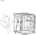
Figure 3 : is the view of the shutter system of the present invention in the open position. -
Figure 4a : is the view of the hole form of the water discharge opening of the shutter system. -
Figure 4b : is the view of the slit form of the water discharge opening of the shutter system. -
- 1. Dishwasher
- 2. Vent opening
- 3. Shutter box
- 4. Shutter plate
- 5. Water inlet opening
- 6. Water discharge opening
- The shutter system of the present invention is developed to discharge the moisture in the washing tub to the outside in a controlled manner. By means of said shutter system, less moisture is discharged out of the cabinet and any wetness and moisture is prevented from forming on the body of the dishwasher. Thus, possible insulation deformations and component failures are prevented. Continuous heat and moisture discharge from the vent hole on the dishwasher is prevented, thus reducing energy loss.
- By means of the present invention, a system is disclosed, providing low cost and low energy consumption in the drying phase of a dishwasher comprising a vent drying system. By means of the present invention, air replenishment by means of a controlled air infiltration opening and controlled humid air discharge are ensured. In said system, hot and humid air in the dishwasher is discharged out of the dishwasher through the vent opening, and fresh air is supplied to the dishwasher through the air infiltration opening. The heated air in the dishwasher rises and is discharged through the vent opening above while relative humidity in the dishwasher is reduced and better drying performance is obtained by supplying fresh air to the inside through the infiltration opening.
- The dishwasher of the present invention comprises a body; a washing tub which is provided in the body and wherein the washing process is performed; at least one spraying member which is provided in the washing tub and which provides the delivery of water to the dishes; a heater which is provided in the body and which provides the heating of the water delivered on the dishes; and at least one vent which is positioned near or on the ceiling of the washing tub and which ensures that the moist air generated by the hot water is removed from the dishes when the drying step starts.
- In the system and method of the present invention, a shutter system is developed to partially or completely close the vent for discharging the moist air in a controlled manner. The purpose of said shutter system is to completely or partially close the vent opening, which is always open in a full cycle (cold wash, main wash, rinsing and drying), during the main washing and rinsing step, so as to prevent the discharge of moist air to the outside. Thus, loss of energy is prevented.
- The shutter system is developed based on the principle of the buoyant force of water and does not require energy. The shutter system comprises a box (3) which is placed under the vent opening (2) (Fan pocket hole); a plate (4) which is manufactured from a material with a density less than water and which is placed in the box (3); a water inlet opening (5) which enables the water to enter the box (3) and also enables the plate (4) to rise; and a water discharge opening (6) which is arranged at the bottom of the box (3) and which enables the water to be discharged out of the box (3). The shutter plate (4) is manufactured from a material resistant to detergent and temperature, preferably from foam (styrofoam), more preferably from polystyrene foam or polyurethane foam. The opening (6) provided at the bottom of the box (3) enables the water to be discharged out of the box (3) when the drying phase starts. The opening (6) can be in the form of one or more holes, preferably in the form of cones (
Figure 4a ), or can be in the form of one or more slits, preferably in the form of flaps (Figure 4b ). - When the cycle starts, water circulation starts in the dishwasher (1) and this circulation continues until the drying step. During the circulation inside, water starts to fill into the box (3) provided under the vent opening (2) through the water inlet opening (5) and the shutter plate (4), which is in its first position in the box (3), starts to rise upwards with the buoyant force of the water. When the box (3) is completely filled with water, the shutter plate (4) shifts to the second position so as to completely or partially close the front of the vent opening (2), thus preventing the humid air in the dishwasher (1) from being discharged through the vent opening (2) during the washing step. The first position of the shutter plate (4) is the position before the water fills into the box (3). The second position of the shutter plate (4) is the position the plate ()4) reaches when the water filling process into the box (3) stops or when the same is prevented from rising further by means of a stopper. The stopper may be tabs on at least one side parallel to the rising direction of the plate (4) so as to prevent the plate (4) from rising by means of the housing or bump-shaped region in the box (3), or may have a different configuration. When the drying step starts, the water in the box (3) is discharged by means of the water discharge opening (6) provided at the bottom of the box (3), the styrofoam goes down again and the vent opening (2) is opened. The flow rate of the water filled into the box (3) must be greater than the flow rate of the water discharged out of the box (3). This is achieved by keeping the water discharge opening (6) as small as possible. Thus, any dirt and clogging are also prevented.
- The shutter box (3) is filled with washing water, but in another preferred embodiment, the box (3) can be continuously supplied with mains water through a water line to be connected directly to the box (3) from the water connection line. If the box (3) is supplied directly with the water to be drawn from the water connection line, the flow rate problem is eliminated, and the number of water discharge openings (6) can be increased accordingly, and by enlarging the opening (6), any clogging due to the dirt which may enter the box (3) is prevented.
- The shutter system can be used not only in dishwashers with a vent drying system, but also in dishwashers with fans. By placing a shutter system in front of the fan pocket opening, energy loss can also be prevented in dishwashers with fans.
- In a preferred embodiment of the present invention, two stoppers are placed on the sides of the plate (4) to prevent the shutter plate (4) from leaving the box (3).
- The edge areas of the pool can be expanded like an umbrella structure such that more water can be filled.
Claims (9)
- A dishwasher (1) comprising a body; a washing tub which is provided in the body and wherein the washing process is performed; at least one spraying member which is provided in the washing tub and which provides the delivery of water to the dishes; a heater which is provided in the body and which provides the heating of the water delivered on the dishes; and at least one vent opening (2) which is positioned near or on the ceiling of the washing tub and which ensures that the moist air generated by the hot water is removed from the dishes when the drying step starts, characterized by, to close the vent opening (2), a shutter system having• a box (3) which is placed under the vent opening (2);• a plate (4) which is manufactured from a material with a density less than water and which is placed in the box (3);• a water inlet opening (5) which enables the water to enter the box (3) and also enables the plate (4) to rise; and• a water discharge opening (6) which is arranged at the bottom of the box (3) and which enables the water to be discharged out of the box (3).
- A dishwasher (1) as in Claim 1, characterized in that the plate (4) is manufactured from foam material.
- A dishwasher (1) as in Claim 2, characterized in that the plate (4) is manufactured from polystyrene foam or polyurethane foam.
- A dishwasher (1) as in Claim 1, characterized in that the water discharge opening (6) comprises at least one hole or slit.
- A dishwasher (1) as in Claim 4, characterized in that the water discharge opening (6) is at least one conic hole.
- A dishwasher (1) as in Claim 4, characterized in that the water discharge opening (6) is at least one flap-shaped slit.
- A dishwasher (1) as in claim 1, characterized by comprising a water line delivering mains water into the box (3).
- A dishwasher (1) as in Claim 1, characterized by comprising a stopper provided on at least one side of the plate (4) parallel to the rising direction.
- An operation method for a dishwasher (1) as in Claim1, characterized by comprising the operational steps of• starting to fill water into the box (3) provided under the vent opening (2) through the water inlet opening (5) as the washing cycle starts,• the shutter plate (4) inside the box (3) rising upwards with the buoyancy of the water,• completely or partially closing the front of the vent opening (2) when the box (3) is completely filled with water, and• discharging the water from the box (3) by means of the discharge opening (6) provided at the bottom of the box (3) as the drying cycle starts and opening the vent opening (2) by returning the shutter plate (4) to the first position.
Applications Claiming Priority (1)
| Application Number | Priority Date | Filing Date | Title |
|---|---|---|---|
| TR202215787 | 2022-10-17 |
Publications (1)
| Publication Number | Publication Date |
|---|---|
| EP4356812A1 true EP4356812A1 (en) | 2024-04-24 |
Family
ID=88236866
Family Applications (1)
| Application Number | Title | Priority Date | Filing Date |
|---|---|---|---|
| EP23200495.2A Pending EP4356812A1 (en) | 2022-10-17 | 2023-09-28 | A dishwasher |
Country Status (1)
| Country | Link |
|---|---|
| EP (1) | EP4356812A1 (en) |
Citations (4)
| Publication number | Priority date | Publication date | Assignee | Title |
|---|---|---|---|---|
| DE2152021A1 (en) * | 1970-10-28 | 1972-05-04 | Electrolux Ab | Arrangement in a dishwasher |
| US3876469A (en) * | 1973-05-23 | 1975-04-08 | Gen Electric | Dish-washer vent system |
| US20060090778A1 (en) * | 2004-11-01 | 2006-05-04 | Oakes Michelle L | Dishwasher modular exhaust vent |
| WO2017018696A1 (en) * | 2015-07-24 | 2017-02-02 | Lg Electronics Inc. | Dishwasher |
-
2023
- 2023-09-28 EP EP23200495.2A patent/EP4356812A1/en active Pending
Patent Citations (4)
| Publication number | Priority date | Publication date | Assignee | Title |
|---|---|---|---|---|
| DE2152021A1 (en) * | 1970-10-28 | 1972-05-04 | Electrolux Ab | Arrangement in a dishwasher |
| US3876469A (en) * | 1973-05-23 | 1975-04-08 | Gen Electric | Dish-washer vent system |
| US20060090778A1 (en) * | 2004-11-01 | 2006-05-04 | Oakes Michelle L | Dishwasher modular exhaust vent |
| WO2017018696A1 (en) * | 2015-07-24 | 2017-02-02 | Lg Electronics Inc. | Dishwasher |
Similar Documents
| Publication | Publication Date | Title |
|---|---|---|
| EP3307133B1 (en) | Heating circulation type drying module of dishwasher | |
| US9078555B2 (en) | Dishwasher and method for operating a dishwasher | |
| US3068877A (en) | Dishwasher | |
| US9895044B2 (en) | Dishwasher with controlled dry cycle | |
| GB2262027A (en) | A dishwasher with a drying cycle | |
| US20170188778A1 (en) | Dishwasher and control method thereof | |
| US20110048472A1 (en) | Dishwasher | |
| KR102384522B1 (en) | Dishwasher | |
| US20070246073A1 (en) | Dishwasher and method of controlling the same | |
| US20170188777A1 (en) | Dishwasher and control method thereof | |
| US11297998B2 (en) | Dishwasher | |
| KR101054553B1 (en) | Dishwashing dryer | |
| JP6982734B2 (en) | dishwasher | |
| AU2018202053B2 (en) | Pump and dishwasher comprising the same | |
| KR20200018014A (en) | Dish Washer | |
| EP3254597B1 (en) | Method for controlling water supply of dishwasher | |
| KR102005441B1 (en) | Dishwasher and method of controlling the same | |
| US20190246870A1 (en) | Dishwasher | |
| US20240366058A1 (en) | Dishwasher and control method therefor | |
| JP6906142B2 (en) | dishwasher | |
| CN217696510U (en) | Feeding device and dish washing machine | |
| JP5731157B2 (en) | Dishwasher | |
| KR101178680B1 (en) | Drying system of dish washer | |
| WO2017088934A1 (en) | Dishwasher and method for drying washed items in a dishwasher | |
| JP2972947B2 (en) | Dishwasher |
Legal Events
| Date | Code | Title | Description |
|---|---|---|---|
| PUAI | Public reference made under article 153(3) epc to a published international application that has entered the european phase |
Free format text: ORIGINAL CODE: 0009012 |
|
| STAA | Information on the status of an ep patent application or granted ep patent |
Free format text: STATUS: REQUEST FOR EXAMINATION WAS MADE |
|
| 17P | Request for examination filed |
Effective date: 20230928 |
|
| AK | Designated contracting states |
Kind code of ref document: A1 Designated state(s): AL AT BE BG CH CY CZ DE DK EE ES FI FR GB GR HR HU IE IS IT LI LT LU LV MC ME MK MT NL NO PL PT RO RS SE SI SK SM TR |