EP4356811A1 - A dishwasher comprising an inner illumination member - Google Patents
A dishwasher comprising an inner illumination member Download PDFInfo
- Publication number
- EP4356811A1 EP4356811A1 EP23200506.6A EP23200506A EP4356811A1 EP 4356811 A1 EP4356811 A1 EP 4356811A1 EP 23200506 A EP23200506 A EP 23200506A EP 4356811 A1 EP4356811 A1 EP 4356811A1
- Authority
- EP
- European Patent Office
- Prior art keywords
- lid
- dishwasher
- guide
- sealing member
- cut
- Prior art date
- Legal status (The legal status is an assumption and is not a legal conclusion. Google has not performed a legal analysis and makes no representation as to the accuracy of the status listed.)
- Withdrawn
Links
- 238000005286 illumination Methods 0.000 title claims abstract description 13
- 238000007789 sealing Methods 0.000 claims abstract description 63
- 238000005406 washing Methods 0.000 description 11
- XLYOFNOQVPJJNP-UHFFFAOYSA-N water Substances O XLYOFNOQVPJJNP-UHFFFAOYSA-N 0.000 description 4
- 210000000078 claw Anatomy 0.000 description 2
- 230000015572 biosynthetic process Effects 0.000 description 1
Images






Classifications
-
- A—HUMAN NECESSITIES
- A47—FURNITURE; DOMESTIC ARTICLES OR APPLIANCES; COFFEE MILLS; SPICE MILLS; SUCTION CLEANERS IN GENERAL
- A47L—DOMESTIC WASHING OR CLEANING; SUCTION CLEANERS IN GENERAL
- A47L15/00—Washing or rinsing machines for crockery or tableware
- A47L15/42—Details
- A47L15/4246—Details of the tub
Definitions
- the present invention relates to a dishwasher which is illuminated by means of at least one illumination member disposed in the washing tub.
- washing tub In dishwashers, various types of illumination members are placed on the walls of the washing tub to illuminate the interior of the washing tub.
- the washing tub is an environment which is in constant contact with water and water vapor during the placing of the dishes and the washing of the dishes. Therefore, the impermeability of the walls of the washing tub is very important.
- it is necessary to pay attention to providing proper water tightness to the volume where the illumination member is disposed and to the outside of the washing tub, and to providing proper water tightness equally on all surfaces.
- sealing is achieved by rotating the back part and squeezing the gasket between the front part and the rear part.
- a dishwasher comprising a circular light source which is disposed on the upper wall of the washing tub.
- an illumination member is disclosed, which is disposed at the inner side of the door of the dishwasher.
- the aim of the present invention is the realization of a dishwasher which is illuminated by means of at least one illumination member disposed in the washing tub.
- the dishwasher realized in order to attain the aim of the present invention, explicated in the first claim and the respective claims thereof, comprises a first transparent lid which is disposed on the side of cut-out facing the inside of the body; a sealing member which is disposed between the first lid and the body; and a second lid which enables the force to be applied to the body such that the sealing member remains between the first lid and the body.
- the sealing member is squeezed evenly on all surfaces between the first lid and the body, thereby providing sealing effectively.
- the sealing member is effectively squeezed, thus providing sealing on a larger contact surface.
- the light emitted by the illumination member disposed behind the first lid reaches the inside of the body and illuminates the inside of the body.
- the illumination member can be used for illumination purposes and for hygiene purposes.
- the dishwasher comprises a quadrangular sealing member which is completely seated onto the housing between the base and the body, which, at the center thereof, has a gap in a form matching that of the cut-out and a skirt surrounds the cut-out.
- the sealing member is mounted on the housing on the first lid and seated on the cut-out, the sealing member is squeezed between the body and the base and the skirt surrounds the wall of the cut-out.
- the first lid is positioned such that the long side thereof extends along the horizontal plane.
- the first lid is positioned such that the long side thereof extends along the vertical plane.
- the second lid is composed of two equal half parts.
- the sealing member is enabled to be squeezed in the most effective manner.
- the two parts forming the second lid can move towards each other in the horizontal plane and can move towards each other in the vertical plane, thus enabling the sealing member to be squeezed.
- the position of the two parts varies according to the positioning of the first lid in the horizontal or vertical plane.
- the first and second parts are actually two identical half parts, and in the preferred embodiment, where the first and second parts are attached onto the guide, the first and second parts are driven towards each other from the bottom and the top and bear against each other by moving on the guide. In this case, the first and second parts completely wrap the guide from the bottom, top and sides, and the second lid is attached to the first lid.
- the first part is mounted on the first lid such that the first set engages with the guide from the bottom and the first abutment surface fully bears against the side wall of the guide.
- the first set is driven on the guide and pushed upwards and the movement of the first part ends when the lower edge of the first set bears against the lower edge of the guide.
- the first part is attached to one half of the first part.
- the first abutment surface is completely seated onto the side and bottom wall of the guide and compresses the part of the first lid where the first part is attached towards the body such that the sealing member remains therebetween.
- the second part is mounted on the first lid such that the second set engages with the guide from the top and the second abutment surface fully bears against the side wall of the guide.
- the second set is driven on the guide and pushed downwards and the movement of the second part ends when the upper edge of the second set bears against the upper edge of the guide.
- the second part is attached to one half of the first part.
- the second abutment surface is completely seated onto the side and bottom wall of the guide and compresses the part of the first lid where the second part is attached towards the body such that the sealing member remains therebetween.
- the second part bears against the first part as well, and the second part is seated on the other half of the first lid, thus enabling the second lid to be fully attached to the first lid.
- the first lid is pulled towards the body by means of the second lid such that the sealing member remains therebetween, enabling the sealing member to be fully squeezed along the first and second abutment surfaces.
- the sealing member is seated into the housing on the first lid. Then, the first lid with the sealing member attached thereon is attached to the cut-out on the body wall. When the first lid is attached to the cut-out, the sealing member is positioned between the base and the body, and the skirt surrounds the wall of the cut-out. Moreover, the guide passes to the other side of the cut-out to be positioned between the body and the casing. Then, the first part is mounted on the first lid such that the first set engages with the guide from the bottom and the first abutment surface fully bears against the side wall of the guide. The first set is driven on the guide and pushed upwards until the lower edge of the first set bears against the lower edge of the guide.
- the movement of the first part on the first lid ends.
- the first abutment surface is completely seated onto the side and bottom walls of the guide and compresses the part of the first lid where the first part is attached towards the body such that the sealing member remains therebetween.
- the second part is mounted on the first lid such that the second set engages with the guide from the top and the second abutment surface fully bears against the side wall of the guide.
- the second set is driven on the guide and pushed upwards until the upper edge of the second set bears against the upper edge of the guide.
- the second part When the upper edge of the second set bears against the upper edge of the guide, the second part bears against the first part and the movement of the second part on the first lid ends.
- the second abutment surface is completely seated onto the side and bottom wall of the guide and compresses the part of the first lid where the second part is attached towards the body such that the sealing member remains therebetween.
- the second locking member on the second part is locked to the first locking protrusion on the first part
- the first locking member on the first part is locked to the second locking protrusion on the second part
- the second lid is squeezed on the first lid such that the sealing member remains between the body and the first lid.
- the first lid is pulled towards the body by means of the second lid such that the sealing member remains therebetween, enabling the sealing member to be fully squeezed along the first and second abutment surfaces without any gap therebetween.
- the quadrangular first lid is enabled to be mounted on the body by providing an effective sealing.
- the sealing member is squeezed and crushed in a complete and homogeneous manner along the entire surface in the assembly area.
- the sealing of the dishwasher is improved, and safety and quality are increased.
- screws and similar fixing members are not used, both cost and time savings are provided.
- the dishwasher (1) comprises a casing; a body (2) which is surrounded by the casing; at least one cut-out (3) which is provided on the body (2); at least one first lid (4) which is provided on the side of the cut-out (3) facing the inside of the body (2); an illumination member which is disposed behind the first lid (4); a guide (7) which is provided on the first lid (4) and which extends to the other side of the body (2) so as to be positioned between the body (2) and the casing; at least one sealing member (8) which is disposed between the first lid (4) and the body (2); and at least one second lid (10) which is positioned between the casing and the body (2), which is fitted over the guide (7) so as to surround the same and which enables a force to be applied towards the body (2) such that the sealing member (8) remains between the first lid (4) and the body (2).
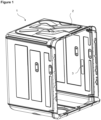
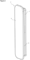
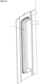
- the entire surface of the sealing member (8) is squeezed evenly between the first lid (4) and the body (2), thereby providing sealing effectively ( Figure 1 , Figure 2 and Figure 3 ).
- the first lid (4) is quadrangular. In the preferred embodiment of the present invention, the first lid (4) is in the form of a quadrangle with rounded corners. In this embodiment of the present invention, the cut-out (3) and the sealing member (8) are in the same form as the first lid (4).
- the dishwasher (1) comprises a base (5) which is provided on the first lid (4) and which faces the inside of the body (2) and a housing (6) which extends perpendicular to the base (5) on the rear surface of the base (5) and whereon the sealing member (8) is seated.
- the base (5) is translucent and is transparent or semitransparent ( Figure 4 ).
- the dishwasher (1) comprises a quadrangular sealing member (8) which is completely seated onto the housing (6) between the base (5) and the body (2), which, at the center thereof, has a gap in a form matching that of the cut-out (3) and a skirt (9) surrounds the cut-out (3).
- the sealing member (8) is mounted on the housing (6) on the first lid (4) and seated on the cut-out (3), the sealing member (8) is squeezed between the body (2) and the base (5) and the skirt (9) surrounds the wall of the cut-out (3) ( Figure 5 and Figure 6 ).
- the guide (7) is in the form of a groove all around, provided following the housing (6).
- the first lid (4) is positioned such that the long side thereof extends along the vertical plane.
- the first lid (4) is positioned such that the long side thereof extends along the horizontal plane.
- the second lid (10) comprises a first part (11) in the form of "U”, which completely surrounds one side of the guide (7) and partially surrounds the two parallel sides perpendicular to this side, and a second part (16) in the form of "U”, which completely surrounds the other side and partially surrounds the two parallel sides perpendicular to this side.
- first and second parts (11 and 16) are driven towards each other and bear against each other by moving on the guide (7).
- the first and second parts (11 and 16) completely surround the guide (7) on all sides and the second lid (10) is attached to the first lid (4) ( Figure 9 , Figure 10 , Figure 11 ).
- the dishwasher (1) comprises a first set (12) which extends all around the edges of the first part (11), perpendicular to the edges, towards the center of the first part (11) and a first abutment surface (13) which is provided on the first set (12) along the first set (12) and which bears against the side wall of the guide (7).
- the first part (11) is attached on the first lid (4) such that the first set (12) engages with the guide (7) and the first abutment surface (13) fully bears against the side wall of the guide (7).
- the first part (11) By driving the first set (12) on the guide (7), the first part (11) is pushed sideways or upwards, respectively, depending on whether the first lid (4) extends in the horizontal or vertical plane, and the movement of the first part (11) ends when the edge of the first set (12) bears against the adjacent edge of the guide (7).
- the first part (11) is attached to one half of the first part (4).
- the first abutment surface (13) is completely seated onto the walls of the guide (7) and compresses the part of the first lid (4) where the first part (11) is attached towards the body (2) such that the sealing member (8) remains therebetween ( Figure 7 and Figure 8 ).
- the dishwasher (1) comprises a second set (17) which extends all around the edges of the second part (16), perpendicular to the edges, towards the center of the second part (16) and a second abutment surface (18) which is provided on the second set (17) along the second set (17) and which bears against the side wall of the guide (7).
- the second part (16) is attached on the first lid (4) such that the second set (17) engages with the guide (7) and the second abutment surface (18) fully bears against the side wall of the guide (7).
- the second part (16) By driving the second set (12) on the guide (7), the second part (16) is pushed sideways or downwards, respectively, depending on whether the first lid (4) extends in the horizontal or vertical plane, and the movement of the second part (16) ends when the edge of the second set (17) bears against the upper adjacent edge of the guide (7).
- the second part (16) is attached to one half of the first part (4).
- the second abutment surface (18) is completely seated onto the walls of the guide (7) and compresses the part of the first lid (4) where the second part (16) is attached towards the body (2) such that the sealing member (8) remains therebetween.
- the second part (16) bears against the first part (11) as well, and the second part (16) is seated on the other half of the first lid (4), thus enabling the second lid (10) to be fully attached to the first lid (4).
- the first lid (4) is pulled towards the body (2) by means of the second lid (10) such that the sealing member (8) remains therebetween, enabling the sealing member (8) to be fully squeezed along the first and second abutment surfaces (13 and 18).
- the dishwasher (1) comprises a first locking protrusion (14) which is provided on the side wall of the first part (11) and a first locking member (15) which is provided on the other side wall thereof, and a second locking protrusion (not shown in the figures) which is provided on the side wall of the second part (16) and which engages with the first locking member (15) and a second locking member (19) which is provided on the other side wall and which engages with the first locking protrusion (14) ( Figure 12 ).
- the sealing member (8) is seated into the housing (6) on the first lid (4). Then, the first lid (4) with the sealing member (8) attached thereon is attached to the cut-out (3) on the body (2) wall. When the first lid (4) is attached to the cut-out (3), the sealing member (8) is positioned between the base (5) and the body (2), and the skirt (9) surrounds the wall of the cut-out (3). Moreover, the guide (7) passes to the other side of the cut-out (3) to be positioned between the body (2) and the casing.
- the first part (11) is attached on the first lid (4) such that the first set (12) engages with the guide (7) from the bottom and the first abutment surface (13) fully bears against the side wall of the guide (7).
- the first set (12) is driven on the guide (7) and pushed upwards until the lower edge of the first set (12) bears against the lower edge of the guide (7).
- the movement of the first part (11) on the first lid (4) ends.
- the first abutment surface (13) is completely seated onto the side and bottom walls of the guide (7) and compresses the part of the first lid (4) where the first part (11) is attached towards the body (2) such that the sealing member (8) remains therebetween.
- the second part (16) is attached on the first lid (4) such that the second set (17) engages with the guide (7) from the top and the second abutment surface (18) fully bears against the side wall of the guide (7).
- the second set (17) is driven on the guide (7) and pushed upwards until the upper edge of the second set (17) bears against the upper edge of the guide (7).
- the second part (16) bears against the first part (11) and the movement of the second part (11) on the first lid (4) ends.
- the second abutment surface (18) is completely seated onto the side and upper walls of the guide (7) and compresses the part of the first lid (4) where the second part (16) is attached towards the body (2) such that the sealing member (8) remains therebetween.
- the second locking member (19) on the second part (6) is locked to the first locking protrusion (14) on the first part (11), and the first locking member (15) on the first part (11) is locked to the second locking protrusion on the second part (16), and the second lid (10) is squeezed on the first lid (4) such that the sealing member (8) remains between the body (2) and the first lid (4).
- the first lid (4) is pulled towards the body (2) by means of the second lid (10) such that the sealing member (8) remains therebetween, enabling the sealing member (8) to be fully squeezed along the first and second abutment surfaces (13 and 18) without any gap therebetween ( Figure 13 and Figure 14 ).
- the quadrangular first lid (4) is enabled to be mounted on the body (2) by providing an effective sealing.
- the sealing member (8) is squeezed and crushed in a complete and homogeneous manner along the entire surface in the assembly area.
- the sealing of the dishwasher (1) is improved, and safety and quality are increased.
- screws and similar fixing members are not used, both cost and time savings are provided.
Landscapes
- Washing And Drying Of Tableware (AREA)
Abstract
The present invention relates to a dishwasher (1) comprising a casing; a body (2) which is surrounded by the casing; at least one cut-out (3) which is provided on the body (2); at least one first lid (4) which is provided on the side of the cut-out (3) facing the inside of the body (2); an illumination member which is disposed behind the first lid (4); a guide (7) which is provided on the first lid (4) and which extends to the other side of the body (2) so as to be positioned between the body (2) and the casing; at least one sealing member (8) which is disposed between the first lid (4) and the body (2); and at least one second lid (10) which is positioned between the casing and the body (2), which is fitted over the guide (7) so as to surround the same and which enables a force to be applied towards the body (2) such that the sealing member (8) remains between the first lid (4) and the body (2).
Description
- The present invention relates to a dishwasher which is illuminated by means of at least one illumination member disposed in the washing tub.
- In dishwashers, various types of illumination members are placed on the walls of the washing tub to illuminate the interior of the washing tub. The washing tub is an environment which is in constant contact with water and water vapor during the placing of the dishes and the washing of the dishes. Therefore, the impermeability of the walls of the washing tub is very important. Especially in washing tubs where illumination members are placed on the wall, it is necessary to pay attention to providing proper water tightness to the volume where the illumination member is disposed and to the outside of the washing tub, and to providing proper water tightness equally on all surfaces. In the state of the art, sealing is achieved by rotating the back part and squeezing the gasket between the front part and the rear part.
- In the state of the art, in order to provide wide and rectangular sealing in the washing tub, the gasket must be squeezed equally on all surfaces to ensure sealing. Even if the gasket is pulled with a screw or claw, the continuity of the desired sealing cannot be achieved since the surface between two claws or between two screws is long.
- In the state of the art Chinese Utility Model Document Application No.
CN207734123 , a dishwasher is disclosed, comprising a circular light source which is disposed on the upper wall of the washing tub. - In the state of the art Chinese Utility Model Document Application No.
CN210871409 , an illumination member is disclosed, which is disposed at the inner side of the door of the dishwasher. - The aim of the present invention is the realization of a dishwasher which is illuminated by means of at least one illumination member disposed in the washing tub.
- The dishwasher realized in order to attain the aim of the present invention, explicated in the first claim and the respective claims thereof, comprises a first transparent lid which is disposed on the side of cut-out facing the inside of the body; a sealing member which is disposed between the first lid and the body; and a second lid which enables the force to be applied to the body such that the sealing member remains between the first lid and the body. Thus, the sealing member is squeezed evenly on all surfaces between the first lid and the body, thereby providing sealing effectively.
- In the embodiments of the present invention where a quadrangular and large surface first lid is used, the sealing member is effectively squeezed, thus providing sealing on a larger contact surface.
- The light emitted by the illumination member disposed behind the first lid reaches the inside of the body and illuminates the inside of the body. The illumination member can be used for illumination purposes and for hygiene purposes.
- In an embodiment of the present invention, the dishwasher comprises a quadrangular sealing member which is completely seated onto the housing between the base and the body, which, at the center thereof, has a gap in a form matching that of the cut-out and a skirt surrounds the cut-out. When the sealing member is mounted on the housing on the first lid and seated on the cut-out, the sealing member is squeezed between the body and the base and the skirt surrounds the wall of the cut-out. Thus, formation of any gap between the cut-out and the body whereon the first lid is seated is prevented and a complete sealing is ensured.
- In an embodiment of the present invention, the first lid is positioned such that the long side thereof extends along the horizontal plane.
- In the preferred embodiment of the present invention, the first lid is positioned such that the long side thereof extends along the vertical plane.
- In the preferred embodiment of the present invention, the second lid is composed of two equal half parts. Thus, in an embodiment wherein a quadrangular first lid is used, the sealing member is enabled to be squeezed in the most effective manner. The two parts forming the second lid can move towards each other in the horizontal plane and can move towards each other in the vertical plane, thus enabling the sealing member to be squeezed. The position of the two parts varies according to the positioning of the first lid in the horizontal or vertical plane. The first and second parts are actually two identical half parts, and in the preferred embodiment, where the first and second parts are attached onto the guide, the first and second parts are driven towards each other from the bottom and the top and bear against each other by moving on the guide. In this case, the first and second parts completely wrap the guide from the bottom, top and sides, and the second lid is attached to the first lid.
- In the preferred embodiment of the present invention, the first part is mounted on the first lid such that the first set engages with the guide from the bottom and the first abutment surface fully bears against the side wall of the guide. The first set is driven on the guide and pushed upwards and the movement of the first part ends when the lower edge of the first set bears against the lower edge of the guide. Thus, the first part is attached to one half of the first part. In this embodiment, the first abutment surface is completely seated onto the side and bottom wall of the guide and compresses the part of the first lid where the first part is attached towards the body such that the sealing member remains therebetween.
- In the preferred embodiment of the present invention, the second part is mounted on the first lid such that the second set engages with the guide from the top and the second abutment surface fully bears against the side wall of the guide. The second set is driven on the guide and pushed downwards and the movement of the second part ends when the upper edge of the second set bears against the upper edge of the guide. Thus, the second part is attached to one half of the first part. In this embodiment, the second abutment surface is completely seated onto the side and bottom wall of the guide and compresses the part of the first lid where the second part is attached towards the body such that the sealing member remains therebetween. In this case, the second part bears against the first part as well, and the second part is seated on the other half of the first lid, thus enabling the second lid to be fully attached to the first lid. Thus, the first lid is pulled towards the body by means of the second lid such that the sealing member remains therebetween, enabling the sealing member to be fully squeezed along the first and second abutment surfaces.
- In the preferred embodiment of the present invention, the sealing member is seated into the housing on the first lid. Then, the first lid with the sealing member attached thereon is attached to the cut-out on the body wall. When the first lid is attached to the cut-out, the sealing member is positioned between the base and the body, and the skirt surrounds the wall of the cut-out. Moreover, the guide passes to the other side of the cut-out to be positioned between the body and the casing. Then, the first part is mounted on the first lid such that the first set engages with the guide from the bottom and the first abutment surface fully bears against the side wall of the guide. The first set is driven on the guide and pushed upwards until the lower edge of the first set bears against the lower edge of the guide. When the lower edge of the first set bears against the lower edge of the guide, the movement of the first part on the first lid ends. In this case, the first abutment surface is completely seated onto the side and bottom walls of the guide and compresses the part of the first lid where the first part is attached towards the body such that the sealing member remains therebetween. Afterwards, the second part is mounted on the first lid such that the second set engages with the guide from the top and the second abutment surface fully bears against the side wall of the guide. The second set is driven on the guide and pushed upwards until the upper edge of the second set bears against the upper edge of the guide. When the upper edge of the second set bears against the upper edge of the guide, the second part bears against the first part and the movement of the second part on the first lid ends. In this case, the second abutment surface is completely seated onto the side and bottom wall of the guide and compresses the part of the first lid where the second part is attached towards the body such that the sealing member remains therebetween. At the same time, the second locking member on the second part is locked to the first locking protrusion on the first part, and the first locking member on the first part is locked to the second locking protrusion on the second part, and the second lid is squeezed on the first lid such that the sealing member remains between the body and the first lid. Thus, the first lid is pulled towards the body by means of the second lid such that the sealing member remains therebetween, enabling the sealing member to be fully squeezed along the first and second abutment surfaces without any gap therebetween.
- By means of the present invention, the quadrangular first lid is enabled to be mounted on the body by providing an effective sealing. The sealing member is squeezed and crushed in a complete and homogeneous manner along the entire surface in the assembly area. Thus, the sealing of the dishwasher is improved, and safety and quality are increased. Moreover, since screws and similar fixing members are not used, both cost and time savings are provided.
- A dishwasher realized in order to attain the aim of the present invention is illustrated in the attached figures, where:
-
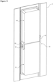
Figure 1 - is the perspective view of a dishwasher body. -
Figure 2 - is the front view of the first lid. -
Figure 3 - is the exploded view of the first lid, the sealing member and the cut-out. -
Figure 4 - is the front perspective view of the first lid when attached to the body. -
Figure 5 - is the rear perspective view of the first lid when attached to the body. -
Figure 6 - is the sideways perspective view of the first lid when attached to the body. -
Figure 7 - is the perspective view of the first part. -
Figure 8 - is the view of the cross-section A-A inFigure 7 . -
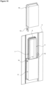
Figure 9 - is the perspective view of the first part while being attached to the first lid. -
Figure 10 - is the perspective view of the second part while being attached to the first lid. -
Figure 11 - is the perspective view of the second part when attached to the first lid. -
Figure 12 - is the rear view of the second part when attached to the first lid. -
Figure 13 - is the view of the cross-section B-B inFigure 12 . -
Figure 14 - is the view of the cross section C-C inFigure 12 . - The elements illustrated in the figures are numbered as follows:
- 1. Dishwasher
- 2. Body
- 3. Cut-out
- 4. First lid
- 5. Base
- 6. Housing
- 7. Guide
- 8. Sealing member
- 9. Skirt
- 10. Second lid
- 11. First part
- 12. First set
- 13. First abutment surface
- 14. First locking protrusion
- 15. First locking member
- 16. Second part
- 17. Second set
- 18. Second abutment surface
- 19. Second locking member
- The dishwasher (1) comprises a casing; a body (2) which is surrounded by the casing; at least one cut-out (3) which is provided on the body (2); at least one first lid (4) which is provided on the side of the cut-out (3) facing the inside of the body (2); an illumination member which is disposed behind the first lid (4); a guide (7) which is provided on the first lid (4) and which extends to the other side of the body (2) so as to be positioned between the body (2) and the casing; at least one sealing member (8) which is disposed between the first lid (4) and the body (2); and at least one second lid (10) which is positioned between the casing and the body (2), which is fitted over the guide (7) so as to surround the same and which enables a force to be applied towards the body (2) such that the sealing member (8) remains between the first lid (4) and the body (2). Thus, the entire surface of the sealing member (8) is squeezed evenly between the first lid (4) and the body (2), thereby providing sealing effectively (
Figure 1 ,Figure 2 andFigure 3 ). - In an embodiment of the present invention, the first lid (4) is quadrangular. In the preferred embodiment of the present invention, the first lid (4) is in the form of a quadrangle with rounded corners. In this embodiment of the present invention, the cut-out (3) and the sealing member (8) are in the same form as the first lid (4).
- In an embodiment of the present invention, the dishwasher (1) comprises a base (5) which is provided on the first lid (4) and which faces the inside of the body (2) and a housing (6) which extends perpendicular to the base (5) on the rear surface of the base (5) and whereon the sealing member (8) is seated. When the first lid (4) is fitted into the cut-out (3), the base and the housing (6) are positioned in the body (2). In this embodiment of the present invention, the base (5) is translucent and is transparent or semitransparent (
Figure 4 ). - In an embodiment of the present invention, the dishwasher (1) comprises a quadrangular sealing member (8) which is completely seated onto the housing (6) between the base (5) and the body (2), which, at the center thereof, has a gap in a form matching that of the cut-out (3) and a skirt (9) surrounds the cut-out (3). When the sealing member (8) is mounted on the housing (6) on the first lid (4) and seated on the cut-out (3), the sealing member (8) is squeezed between the body (2) and the base (5) and the skirt (9) surrounds the wall of the cut-out (3) (
Figure 5 andFigure 6 ). - In the embodiment of the present invention, the guide (7) is in the form of a groove all around, provided following the housing (6).
- In the preferred embodiment of the present invention, the first lid (4) is positioned such that the long side thereof extends along the vertical plane.
- In another embodiment of the present invention, the first lid (4) is positioned such that the long side thereof extends along the horizontal plane.
- In the preferred embodiment of the present invention, the second lid (10) comprises a first part (11) in the form of "U", which completely surrounds one side of the guide (7) and partially surrounds the two parallel sides perpendicular to this side, and a second part (16) in the form of "U", which completely surrounds the other side and partially surrounds the two parallel sides perpendicular to this side. When attached to the guide (7), the first and second parts (11 and 16) are driven towards each other and bear against each other by moving on the guide (7). In this case, the first and second parts (11 and 16) completely surround the guide (7) on all sides and the second lid (10) is attached to the first lid (4) (
Figure 9 ,Figure 10 ,Figure 11 ). - In the embodiment of the present invention, the dishwasher (1) comprises a first set (12) which extends all around the edges of the first part (11), perpendicular to the edges, towards the center of the first part (11) and a first abutment surface (13) which is provided on the first set (12) along the first set (12) and which bears against the side wall of the guide (7). The first part (11) is attached on the first lid (4) such that the first set (12) engages with the guide (7) and the first abutment surface (13) fully bears against the side wall of the guide (7). By driving the first set (12) on the guide (7), the first part (11) is pushed sideways or upwards, respectively, depending on whether the first lid (4) extends in the horizontal or vertical plane, and the movement of the first part (11) ends when the edge of the first set (12) bears against the adjacent edge of the guide (7). Thus, the first part (11) is attached to one half of the first part (4). In this embodiment , the first abutment surface (13) is completely seated onto the walls of the guide (7) and compresses the part of the first lid (4) where the first part (11) is attached towards the body (2) such that the sealing member (8) remains therebetween (
Figure 7 andFigure 8 ). - In the embodiment of the present invention, the dishwasher (1) comprises a second set (17) which extends all around the edges of the second part (16), perpendicular to the edges, towards the center of the second part (16) and a second abutment surface (18) which is provided on the second set (17) along the second set (17) and which bears against the side wall of the guide (7). The second part (16) is attached on the first lid (4) such that the second set (17) engages with the guide (7) and the second abutment surface (18) fully bears against the side wall of the guide (7). By driving the second set (12) on the guide (7), the second part (16) is pushed sideways or downwards, respectively, depending on whether the first lid (4) extends in the horizontal or vertical plane, and the movement of the second part (16) ends when the edge of the second set (17) bears against the upper adjacent edge of the guide (7). Thus, the second part (16) is attached to one half of the first part (4). In this embodiment , the second abutment surface (18) is completely seated onto the walls of the guide (7) and compresses the part of the first lid (4) where the second part (16) is attached towards the body (2) such that the sealing member (8) remains therebetween. In this case, the second part (16) bears against the first part (11) as well, and the second part (16) is seated on the other half of the first lid (4), thus enabling the second lid (10) to be fully attached to the first lid (4). Thus, the first lid (4) is pulled towards the body (2) by means of the second lid (10) such that the sealing member (8) remains therebetween, enabling the sealing member (8) to be fully squeezed along the first and second abutment surfaces (13 and 18).
- In an embodiment of the present invention, the dishwasher (1) comprises a first locking protrusion (14) which is provided on the side wall of the first part (11) and a first locking member (15) which is provided on the other side wall thereof, and a second locking protrusion (not shown in the figures) which is provided on the side wall of the second part (16) and which engages with the first locking member (15) and a second locking member (19) which is provided on the other side wall and which engages with the first locking protrusion (14) (
Figure 12 ). - In the preferred embodiment of the present invention, the sealing member (8) is seated into the housing (6) on the first lid (4). Then, the first lid (4) with the sealing member (8) attached thereon is attached to the cut-out (3) on the body (2) wall. When the first lid (4) is attached to the cut-out (3), the sealing member (8) is positioned between the base (5) and the body (2), and the skirt (9) surrounds the wall of the cut-out (3). Moreover, the guide (7) passes to the other side of the cut-out (3) to be positioned between the body (2) and the casing. Then, the first part (11) is attached on the first lid (4) such that the first set (12) engages with the guide (7) from the bottom and the first abutment surface (13) fully bears against the side wall of the guide (7). The first set (12) is driven on the guide (7) and pushed upwards until the lower edge of the first set (12) bears against the lower edge of the guide (7). When the lower edge of the first set (12) bears against the lower edge of the guide (7), the movement of the first part (11) on the first lid (4) ends. In this case, the first abutment surface (13) is completely seated onto the side and bottom walls of the guide (7) and compresses the part of the first lid (4) where the first part (11) is attached towards the body (2) such that the sealing member (8) remains therebetween. Afterwards, the second part (16) is attached on the first lid (4) such that the second set (17) engages with the guide (7) from the top and the second abutment surface (18) fully bears against the side wall of the guide (7). The second set (17) is driven on the guide (7) and pushed upwards until the upper edge of the second set (17) bears against the upper edge of the guide (7). When the upper edge of the second set (17) bears against the upper edge of the guide (7), the second part (16) bears against the first part (11) and the movement of the second part (11) on the first lid (4) ends. In this case, the second abutment surface (18) is completely seated onto the side and upper walls of the guide (7) and compresses the part of the first lid (4) where the second part (16) is attached towards the body (2) such that the sealing member (8) remains therebetween. At the same time, the second locking member (19) on the second part (6) is locked to the first locking protrusion (14) on the first part (11), and the first locking member (15) on the first part (11) is locked to the second locking protrusion on the second part (16), and the second lid (10) is squeezed on the first lid (4) such that the sealing member (8) remains between the body (2) and the first lid (4). Thus, the first lid (4) is pulled towards the body (2) by means of the second lid (10) such that the sealing member (8) remains therebetween, enabling the sealing member (8) to be fully squeezed along the first and second abutment surfaces (13 and 18) without any gap therebetween (
Figure 13 and Figure 14 ). - By means of the present invention, the quadrangular first lid (4) is enabled to be mounted on the body (2) by providing an effective sealing. The sealing member (8) is squeezed and crushed in a complete and homogeneous manner along the entire surface in the assembly area. Thus, the sealing of the dishwasher (1) is improved, and safety and quality are increased. Moreover, since screws and similar fixing members are not used, both cost and time savings are provided.
Claims (12)
- A dishwasher (1) comprising a casing; a body (2) which is surrounded by the casing; at least one cut-out (3) which is provided on the body (2); at least one first lid (4) which is provided on the side of the cut-out (3) facing the inside of the body (2); and an illumination member which is disposed behind the first lid (4), characterized by a guide (7) which is provided on the first lid (4) and which extends to the other side of the body (2) so as to be positioned between the body (2) and the casing; at least one sealing member (8) which is disposed between the first lid (4) and the body (2); and at least one second lid (10) which is positioned between the casing and the body (2), which is fitted over the guide (7) so as to surround the same and which enables a force to be applied towards the body (2) such that the sealing member (8) remains between the first lid (4) and the body (2).
- A dishwasher (1) as in Claim 1, characterized by the quadrangular first lid (4).
- A dishwasher (1) as in Claim 1, characterized by a base (5) which is provided on the first lid (4) and which faces the inside of the body (2) and a housing (6) which extends perpendicular to the base (5) on the rear surface of the base (5) and whereon the sealing member (8) is seated.
- A dishwasher (1) as in Claim 3, characterized by the translucent base (5).
- A dishwasher (1) as in Claim 3, characterized by a quadrangular sealing member (8) which is completely seated onto the housing (6) between the base (5) and the body (2), which, at the center thereof, has a gap in a form matching that of the cut-out (3) and a skirt (9) surrounds the cut-out (3).
- A dishwasher (1) as in Claim 1, characterized by the guide (7) which is in the form of a groove all around, provided following the housing (6).
- A dishwasher (1) as in any one of the above claims, characterized by the first lid (4) which is positioned such that the long side thereof extends along the vertical plane.
- A dishwasher (1) as in any one of Claims 1 to 6, characterized by the first lid (4) which is positioned such that the long side thereof extends along the horizontal plane.
- A dishwasher (1) as in Claim 1, characterized by the second lid (10) comprising a first part (11) in the form of "U", which completely surrounds one side of the guide (7) and partially surrounds the two parallel sides perpendicular to this side, and a second part (16) in the form of "U", which completely surrounds the other side and partially surrounds the two parallel sides perpendicular to this side.
- A dishwasher (1) as in Claim 9, characterized by a first set (12) which extends all around the edges of the first part (11), perpendicular to the edges, towards the center of the first part (11) and a first abutment surface (13) which is provided on the first set (12) along the first set (12) and which bears against the side wall of the guide (7).
- A dishwasher (1) as in Claim 9, characterized by a second set (17) which extends all around the edges of the second part (16), perpendicular to the edges, towards the center of the second part (16) and a second abutment surface (18) which is provided on the second set (17) along the second set (17) and which bears against the side wall of the guide (7).
- A dishwasher (1) as in any one of Claims 9 to 11, characterized by a first locking protrusion (14) which is provided on the side wall of the first part (11) and a first locking member (15) which is provided on the other side wall thereof, and a second locking protrusion which is provided on the side wall of the second part (16) and which engages with the first locking member (15) and a second locking member (19) which is provided on the other side wall and which engages with the first locking protrusion (14) (Figure 1).
Applications Claiming Priority (1)
| Application Number | Priority Date | Filing Date | Title |
|---|---|---|---|
| TR202215790 | 2022-10-17 |
Publications (1)
| Publication Number | Publication Date |
|---|---|
| EP4356811A1 true EP4356811A1 (en) | 2024-04-24 |
Family
ID=88236639
Family Applications (1)
| Application Number | Title | Priority Date | Filing Date |
|---|---|---|---|
| EP23200506.6A Withdrawn EP4356811A1 (en) | 2022-10-17 | 2023-09-28 | A dishwasher comprising an inner illumination member |
Country Status (1)
| Country | Link |
|---|---|
| EP (1) | EP4356811A1 (en) |
Cited By (2)
| Publication number | Priority date | Publication date | Assignee | Title |
|---|---|---|---|---|
| EP4767911A1 (en) * | 2024-12-30 | 2026-07-01 | LG Electronics Inc. | Dishwasher |
| EP4767910A1 (en) * | 2024-12-30 | 2026-07-01 | LG Electronics Inc. | DISHWASHER |
Citations (7)
| Publication number | Priority date | Publication date | Assignee | Title |
|---|---|---|---|---|
| EP1543761A2 (en) * | 2003-12-16 | 2005-06-22 | Samsung Electronics Co., Ltd. | Dishwasher |
| DE102007022572A1 (en) * | 2006-05-15 | 2007-11-22 | Lg Electronics Inc. | Dishwasher sterilizing method, involves inputting instruction for sterilization cycle, and switching on and off sterilization device arranged in tank with periodic predetermined intervals corresponding to input instruction |
| US20100218793A1 (en) * | 2009-02-27 | 2010-09-02 | Electrolux Home Products, Inc. | Lighting device mounting system for household appliance, and associated apparatus and method |
| CN207734123U (en) | 2017-06-16 | 2018-08-17 | 广东格兰仕集团有限公司 | Disinfection illumination device for dish-washing machine |
| CN110151092A (en) * | 2019-07-01 | 2019-08-23 | 珠海格力电器股份有限公司 | Dish washing machine |
| CN210871409U (en) | 2019-08-20 | 2020-06-30 | 珠海格力电器股份有限公司 | Dish washer door body group spare and dish washer |
| CN115104993A (en) * | 2021-03-23 | 2022-09-27 | 佛山市顺德区美的洗涤电器制造有限公司 | Dish-washing machine |
-
2023
- 2023-09-28 EP EP23200506.6A patent/EP4356811A1/en not_active Withdrawn
Patent Citations (7)
| Publication number | Priority date | Publication date | Assignee | Title |
|---|---|---|---|---|
| EP1543761A2 (en) * | 2003-12-16 | 2005-06-22 | Samsung Electronics Co., Ltd. | Dishwasher |
| DE102007022572A1 (en) * | 2006-05-15 | 2007-11-22 | Lg Electronics Inc. | Dishwasher sterilizing method, involves inputting instruction for sterilization cycle, and switching on and off sterilization device arranged in tank with periodic predetermined intervals corresponding to input instruction |
| US20100218793A1 (en) * | 2009-02-27 | 2010-09-02 | Electrolux Home Products, Inc. | Lighting device mounting system for household appliance, and associated apparatus and method |
| CN207734123U (en) | 2017-06-16 | 2018-08-17 | 广东格兰仕集团有限公司 | Disinfection illumination device for dish-washing machine |
| CN110151092A (en) * | 2019-07-01 | 2019-08-23 | 珠海格力电器股份有限公司 | Dish washing machine |
| CN210871409U (en) | 2019-08-20 | 2020-06-30 | 珠海格力电器股份有限公司 | Dish washer door body group spare and dish washer |
| CN115104993A (en) * | 2021-03-23 | 2022-09-27 | 佛山市顺德区美的洗涤电器制造有限公司 | Dish-washing machine |
Cited By (2)
| Publication number | Priority date | Publication date | Assignee | Title |
|---|---|---|---|---|
| EP4767911A1 (en) * | 2024-12-30 | 2026-07-01 | LG Electronics Inc. | Dishwasher |
| EP4767910A1 (en) * | 2024-12-30 | 2026-07-01 | LG Electronics Inc. | DISHWASHER |
Similar Documents
| Publication | Publication Date | Title |
|---|---|---|
| JP3868725B2 (en) | Refrigerator door | |
| US3619592A (en) | Washing machine with illuminated interior | |
| CN113330175B (en) | Door handles for household appliances with specific light guidance and doors and household appliances | |
| CN112450826B (en) | A support device for a drawer-type dishwasher and a dishwasher | |
| CN210121124U (en) | Dishwasher liner structure | |
| RU201041U1 (en) | HARPOON FOR ATTACHING A STRETCH CEILING | |
| US3692377A (en) | Electrical connection box arrangement for appliance | |
| CN112450827B (en) | Inner tank assembly of dishwasher and dishwasher | |
| JP7645704B2 (en) | Lighting device and bathroom unit equipped with same | |
| CN211582978U (en) | Dishwasher liner assembly and dishwasher | |
| CN211355300U (en) | Support device for drawer type dishwasher and dishwasher | |
| CN211355298U (en) | A dishwasher liner assembly | |
| CN211355301U (en) | Dishwasher liner assembly and dishwasher | |
| CN211582979U (en) | A dishwasher liner assembly | |
| CN211355297U (en) | Drawer type is strutting arrangement and dish washer for dish washer | |
| CN111513644B (en) | Dish washer liner and manufacturing method thereof | |
| CN112450822B (en) | A door assembly for a drawer dishwasher inner liner | |
| CN210114415U (en) | Inner container structure of dish washer | |
| CN210121126U (en) | Inner container structure of dish washer | |
| RU23892U1 (en) | OFFICE SECTIONAL PARTITION | |
| CN112450848B (en) | Dish washer inner bag subassembly | |
| CN112450843B (en) | Liner assembly of dish washer and dish washer | |
| CN218074910U (en) | Dishwasher panel assembly and dishwasher | |
| CN112450845B (en) | Liner collet of dish washer and dish washer | |
| CN111685688A (en) | Inner container structure of dish washer |
Legal Events
| Date | Code | Title | Description |
|---|---|---|---|
| PUAI | Public reference made under article 153(3) epc to a published international application that has entered the european phase |
Free format text: ORIGINAL CODE: 0009012 |
|
| STAA | Information on the status of an ep patent application or granted ep patent |
Free format text: STATUS: REQUEST FOR EXAMINATION WAS MADE |
|
| 17P | Request for examination filed |
Effective date: 20230928 |
|
| AK | Designated contracting states |
Kind code of ref document: A1 Designated state(s): AL AT BE BG CH CY CZ DE DK EE ES FI FR GB GR HR HU IE IS IT LI LT LU LV MC ME MK MT NL NO PL PT RO RS SE SI SK SM TR |
|
| STAA | Information on the status of an ep patent application or granted ep patent |
Free format text: STATUS: THE APPLICATION IS DEEMED TO BE WITHDRAWN |
|
| 18D | Application deemed to be withdrawn |
Effective date: 20241025 |