EP4356799B1 - Culinary container storage device - Google Patents
Culinary container storage device Download PDFInfo
- Publication number
- EP4356799B1 EP4356799B1 EP23204605.2A EP23204605A EP4356799B1 EP 4356799 B1 EP4356799 B1 EP 4356799B1 EP 23204605 A EP23204605 A EP 23204605A EP 4356799 B1 EP4356799 B1 EP 4356799B1
- Authority
- EP
- European Patent Office
- Prior art keywords
- wall
- storage device
- divider
- containers
- Prior art date
- Legal status (The legal status is an assumption and is not a legal conclusion. Google has not performed a legal analysis and makes no representation as to the accuracy of the status listed.)
- Active
Links
Images




Classifications
-
- A—HUMAN NECESSITIES
- A47—FURNITURE; DOMESTIC ARTICLES OR APPLIANCES; COFFEE MILLS; SPICE MILLS; SUCTION CLEANERS IN GENERAL
- A47J—KITCHEN EQUIPMENT; COFFEE MILLS; SPICE MILLS; APPARATUS FOR MAKING BEVERAGES
- A47J47/00—Kitchen containers, stands or the like, not provided for in other groups of this subclass; Cutting-boards, e.g. for bread
- A47J47/16—Stands, or holders for kitchen articles
Definitions
- the present disclosure is in the field of culinary storage devices. More specifically, the present disclosure relates to culinary storage devices configured for use with culinary containers.
- kitchens often include numerous containers used for both food storage and preparation. Today, many individuals pre-prepare meals for consumption throughout the week or sort non-perishables in such containers. Accordingly, kitchens include containers of various shapes and sizes, resulting in a need to store such containers.
- Stacking containers does not solve storage dilemmas for users, in fact, stacking containers may create larger problems. For example, in a multi-piece container stack, if a user wants a piece from the bottom, the user must pull all the containers out of the cabinet, and remove said pieces in order to retrieve the desired container. Since container shapes have very particular sizes, the sizes for each type of shape in the market creates a situation where containers from different manufacturers are unable to be stacked upon one another, thus, creating further organizational issues. Moreover, the pieces at the top of a stack are likely to fall or force users to expend more cabinet space to accommodate them. In turn, users will typically opt for space-wasting options that easily stack at the expense of ease of access. Consequently, kitchen storage space is unable to be efficiently maximized.
- CN 109 330 222 discloses a filing cabinet for engineering that comprises a cabinet body, wherein the cabinet body comprises a left side wall, a right side wall, an upperside wall, a lower side wall and a rear side wall, the front side of the cabinet body is hinged with a door, partition plates are arranged in the cabinet body, the partition plates are connected to the left side wall and the right side wall, the partition plates and the cabinet body form a plurality of containing chambers, the two sides of the containing chambers are provided with permeable plates, drying agents are arranged between the permeable plates and the side walls of the cabinet body, the containing chambers are internally provided with a plurality of clamping plates, the clamping plates are connected to the rear side wall of the cabinet body, the clamping plates are internally provided with magnetic devices, one sides of the clamping plates are provided with movable iron plates, the outer sides of the partition plates are provided with control plates, the control plates are provided with control switches and led lamps, and the upper portions of the containing chambers are provided with steriliz
- the techniques described herein relate to a culinary container storage system comprising at least two container storage devices, each of the at least two container storage devices including: a left wall, a right wall, a bottom wall, and a rear wall, wherein the left wall is disposed orthogonal to the rear wall, forming a left-rear juncture, wherein the right wall is disposed orthogonal to the rear wall, forming a right-rear juncture, wherein the rear wall is disposed orthogonal to the bottom wall, forming a rear-bottom juncture, wherein the left wall is disposed orthogonal to the bottom wall, forming a left-bottom juncture, and wherein the right wall is disposed orthogonal to the bottom wall, forming a right-bottom juncture; and a divider in contact with the rear wall and the bottom wall, the divider disposed in parallel to the left wall and the right wall; a left pocket bound by at least the left wall, the rear wall, the bottom wall, and the
- the present invention provides a culinary container storage system according to claim 1.
- the rear wall, the first wall, and the second wall are orthogonal to the bottom wall. In a further embodiment, the first wall and the second wall are orthogonal to the rear wall.
- Each of the at least two storage devices may be comprised of a rigid material.
- the rigid material is medium-density fiberboard.
- the bottom wall, the rear wall, the first wall, the second wall, and the divider attached to both the bottom wall and the rear wall are at least partially covered in a covering.
- the one or magnets are neodymium magnets.
- the first pocket is defined by a first pocket volume and the second pocket is defined by a second pocket volume, wherein the first pocket volume is equal to the second pocket volume.
- Any process described in this application may be performed in any order and may omit any of the steps in the process. Processes may also be combined with other processes or steps of other processes.
- Each of the storage devices 100 comprise a first wall 102, a second wall 104, a rear wall 106, a bottom wall 108, and/or a divider 110.
- the first wall 102, the second wall 104, and/or the rear wall 106 may be disposed orthogonally to the bottom wall 108.
- the storage device may be covered in a covering.
- the first wall 102, the left wall 104, and/or the rear wall 106 may not be disposed orthogonally to the bottom wall 108.
- the first wall 102 and the second wall 104 may be disposed in parallel to one another.
- first wall 102 and the second wall 104 may be disposed orthogonally to the rear wall 106.
- the divider 110 may be disposed in parallel to the first wall 102 and the second wall 104.
- the divider 110 may be disposed orthogonally to the rear wall 106 and/or bottom wall 108.
- a distal end of the second wall 104 and a distal end of the first wall 102 may attach to a first side of the rear wall 106 and/or a second side of the rear wall 106.
- the second wall 104 and the first wall 102 may include rounded edges or corners (described herein as left bullnose 116 and right bullnose 120).
- the second wall 104 and the first wall 102 may include angular edges or corners (i.e., right-angles).
- the left bullnose 116 and/or the right bullnose 120 may be rounded.
- the rounded edges of the left bullnose 116 and/or the right bullnose 120 may enable unobstructed placement and withdrawal of containers within the storage device 100. Accordingly, said bullnoses 116/120 may be less jagged and, thus, less likely to cause snags (as opposed to a sharp ninety-degree corner) when depositing containers within the storage device 100.
- first wall 102 and the rear wall 106 meet perpendicularly to form a left-rear juncture 126. In an alternative embodiment, the first wall 102 and the rear wall 106 do not meet perpendicularly. In a further embodiment, the second wall 104 and the rear wall 106 meet perpendicularly to form a right-rear juncture 128. In another embodiment, the second wall 104 and the rear wall 106 do not meet perpendicularly.
- the left-rear juncture 126 and right-rear juncture 128 may fasten the rear wall 106 to the first wall 102 and/or the second wall 104.
- first wall 102 and the bottom wall 108 may meet to form a left-bottom juncture 130. In such an embodiment, the first wall 102 and the bottom wall 108 may meet perpendicularly. In an embodiment, the second wall 104 and the bottom wall 108 may meet to form a right-bottom juncture 132. In such an embodiment, the second wall 104 and the bottom wall 108 may meet perpendicularly. The left-bottom juncture 130 and the right-bottom juncture 132 may meet to fasten the bottom wall 108 to the first wall 102 and/or the first wall 104.
- the left-rear juncture 126, the right-rear juncture 128, the left-bottom juncture 130, and the right-bottom juncture 132 may provide rigid support to the storage device 100.
- the rear wall 106 and the bottom wall 108 may meet perpendicularly to form a rear-bottom juncture 134.
- the divider 110 is disposed on the rear wall 106 and/or the bottom wall 108. In a further embodiment, the divider 110 may be positioned equidistant from the first wall 102 and/or the second wall 104. In another embodiment, the divider 110 may be shorter than the rear wall 106, the first wall 102, and/or the second wall 104. As a nonlimiting example, the divider 110 may be roughly 70% the height of the rear wall 106, the first wall 102, and/or the second wall 104. However, the divider 110 may be any height equal to or less than the walls. Further, the divider 110 may be roughly 70% the depth of the first wall 102 and/or the second wall 104.
- the divider 110 may be any depth equal to or less than the walls.
- the divider 110 may be sized and adapted to partition the storage device 100 (for example, to provide structure for retention of containers), yet may be unobtrusive enough as to enable withdrawal and deposit of containers within the storage device 100.
- a first pocket 112 is formed between the first wall 102 and the divider 110.
- a second pocket 114 is formed between the divider 110 and the second wall 104.
- the first pocket 112 and the second pocket 114 may comprise the same volumes.
- the volumes of the first pocket 112, and the second pocket 114 may be adjusted as a function of the position of the divider 110.
- the storage device 100 may have a total volume comprising at least the first pocket volume and the first pocket volume.
- the first wall height may be equal to the first wall depth and/or the second wall height may be equal to the second wall depth.
- the first wall 102 and the second wall 104 may be generally square. However, in alternate embodiments the first wall 102 and the second wall 104 may be any suitable dimensions.
- the storage device 100 may be 173 mm wide, 137 mm deep, and/or 137 mm tall.
- the first wall 102 and/or the second wall 104 may be 137 mm tall and/or 137 mm deep.
- the divider 110 may be 90 mm deep and/or 96 mm tall.
- the first wall 102 and/or the second wall 104 may be 5.75 mm thick.
- the divider 110 may be 9 mm thick.
- the first wall 102, the second wall 104, and the divider 110, of the storage device 100 may be any suitable dimensions.
- the storage device 100 further includes one or more magnets 136.
- the one or more magnets 136 may be embedded in the first wall 102 and/or the second wall 104, such that said magnets 136 may be in line with a plane of the first wall 102 and/or the second wall 104.
- the one or more magnets 136 are deposited within one or more magnet wells 138.
- the one or more magnet wells 138 are sized to accept the one or more magnets 136.
- the one or more magnets 136 may be flush with the one or magnet wells 138.
- the one or more magnets 136 may be concealed by the covering (i.e., a fabric disposed over the one or more magnets 136 and the one or more magnet wells 138). In an embodiment, a single magnet may be used. In an alternative embodiment, two or more magnets may be used. In either of the aforementioned embodiments, the one or more magnets 136 of a first storage device 100 may magnetically affix to a second storage device 100.
- the one or more magnets 136 may be circular in shape to allow for seamlessness within the magnet well 138. However, the one or more magnets may be any suitable shape.
- the one or more magnets 136 may be a neodymium magnet (for example, a N38 or N52 neodymium magnet).
- the one or more magnets 136 may be multi-pole or polymagnets, for example, to enable increased available storage device 100 orientations because such magnets may not require a specific orientation to adhere.
- the one or more magnets 136 may have any strength suitable for storing containers and conjoining storage devices 100.
- magnetic coupling may be achieved by placing a first wall 102 and/or second wall 104 of a first storage device 100 in close proximity to a first wall 102 and/or second wall 104 of a second storage device 100.
- the magnetic attraction between the two devices 100 may allow the two devices 100 to reversibly couple.
- the first wall 102 and/or the second wall 104 may include a metallic element configured to induce magnetic coupling between the metallic element and the one or more magnets 136.
- the first wall 102 and/or the second wall 104 containing the one or more magnets 136 may be sufficiently thick, such that the one or more magnets 136 are further distanced from potentially metallic containers stored within the storage device 100. Such an embodiment may reduce unintentional magnetic adherence of a container to the first wall 102 and/or the second wall 104.
- one or more storage devices 100 may be coupled via a hook- and-loop fastener, an adhesive, a button(s), a latch, a locking hinge, or other fastener.
- these alternate fasteners may supplement the one or more magnets 136.
- the storage device 100 may include any number of dividers. Further, the dividers may be positioned in any fashion. In an alternate embodiment, any number of the dividers may be positioned at least one of orthogonally, parallelly, and angled to the first wall 102 and/or the second wall 104. In an embodiment, the dividers may be of a thickness that is equivalent to a thickness of the first wall 102 and/or the second wall 104. Alternatively, the dividers may be of a thickness that is at least one of greater than and less than the first wall 102 and/or the second wall 104. Further, the dividers may be at least one of transparent and opaque.
- the storage device 100 may be comprised of a rigid material.
- Said rigid material may include, but is not limited to, plastic, wood, cardboard, and/or Medium-Density Fiberboard ("MDF").
- MDF Medium-Density Fiberboard
- the storage device 100 or components of the storage device 100 may include the covering.
- the covering may be utilized to prevent culinary containers from slipping from and/or scratching adjacent culinary containers.
- MDF may be used to construct the storage device 100, enabling a rigid structure capable of accepting the covering seamlessly.
- the storage device 100 may be comprised of a non-slip bottom.
- the non-slip bottom may prevent the storage device 100 from slipping while atop a supporting surface.
- the non-slip bottom may be disposed upon a bottom surface of the bottom wall 108.
- the storage device 100 may be composed of a plurality of rigid components (shown above) and a plurality of corresponding covering pieces (shown below), wherein the plurality of rigid components may be comprised of the rigid material.
- the plurality of corresponding covering pieces may be sized to cover at least one of the plurality of rigid components.
- at least one of the plurality of corresponding covering pieces may be sized to the plurality of rigid components.
- one or more of the plurality of covering pieces may include cut-outs (i.e., sized to accept a divider).
- a logo may be printed on at least one of the plurality of corresponding covering pieces, which may cover the first wall 102, the second wall 104, the rear wall 106, and/or the bottom wall 108.
- one or more magnets 136 may be positioned on the first wall 102 and/or the second wall 104. As a nonlimiting example, the one or more magnets 136 may be captured between the rigid material and the covering disposed atop the rigid material. Further, the one or more magnets 136 may be coupled to the corresponding one or more magnet wells 138 via an adhesive. In an alternate embodiment, the one or more magnets 136 may be coupled to the corresponding one or more magnet wells 138 via a hook and loop fastener.
- the plurality of corresponding covering pieces may be fastened to the plurality of rigid components via an adhesive.
- Each rigid component may have a corresponding covering piece.
- glue may be applied to an outer perimeter of the plurality of corresponding covering pieces, such that said perimeter may be wrapped around at least one of the plurality of rigid components.
- provisions of the plurality of rigid components and the plurality of corresponding covering pieces as shown in FIG. 12 , may permit the storage device 100 to maintain the structure described herein.
- Each of the storage device 100 components (the first wall 102, the second wall 104, the rear wall 106, the bottom wall 108, and/or the divider 110) may be equipped with one or more covering pieces.
- the covering pieces may include an overlap when assembled. Such covering pieces and overlap may increase the storage device's 100 water resistance, which is particularly effective for storing containers which have just been washed.
- the covering is waterproof (for example, to promote integrity of the storage device 100 when wet container items are deposited within or adjacent to the storage device 100).
- the covering may be textured (for example, to promote friction such the containers do not move excessively within the storage device 100).
- the covering may be at least one of 720D cotton/linen fabric, 1MM, waterproof, and 200-210gsm.
- the covering may accommodate a weave pattern for texture.
- the covering may be comprised of any suitable textile alternative.
- the covering may be treated with a spray finish, for example, a clear coat finish. Such a spray finish may increase the integrity of the storage device 100 both structurally and aesthetically (for example, preventing stains or providing a surface that is easier to clean).
- the storage device 100 may be configured in a plurality of sizes. In an embodiment, the plurality of sizes may be able to accommodate small and/or large bundles of culinary containers. In a further embodiment, the storage device 100 may be sized to fit any combination and/or quantity of a small culinary container with or without a lid, a medium culinary container with or without a lid, a large culinary container with or without a lid, a dot ramekin/insert with or without a lid, and/or a dash ramekin/insert with or without a lid. However, the storage device may be configured to store any suitable culinary storage device alternative.
- a plurality of storage devices may be conjoined.
- the rear wall of a first storage device may interface with the rear wall of a second storage device and/or the rear wall of a third storage device may interface with the first wall of the first storage device and the second wall of the second storage device.
- one or more magnets 136 may be disposed in the rear wall 106, such that the rear wall 106 of a storage device 100 may reversibly couple with the first wall 102 and/or a wall of another storage device.
- any number of storage devices may be conjoined in any suitable manner.
- the magnet wells 138 are positioned in the first wall 102 and/or the second wall 104 of the first storage device such that adjacent walls of other storage devices may magnetically couple to the first storage device regardless of orientation.
- the magnet wells 138 may be positioned such that the first wall and/or second wall of the first storage device may magnetically couple to a first wall of the second storage device and/or a second wall 104 of the second storage device.
- the divider 110 may adhere to the rear wall 106 and/or the bottom wall 108 prior to application of the covering. Accordingly, the divider 110 may be securely affixed as a function of both an adhesive between the divider 110 and the rear wall 106 and/or the bottom wall 108, and/or the tension and support provided by the covering.
- the plurality of corresponding covering pieces may be sized slightly larger than the surface area of an outer face of at least one of the first wall 102, the second wall 104, the rear wall 106, and the bottom wall 108 such that the outer perimeter may wrap around the first wall 102, the second wall 104, the rear wall 106, and/or the bottom wall 108.
- said covering may partially cover the inner surfaces of the first wall 102, the second wall 104, the rear wall 106, and/or the bottom wall 108. Accordingly, one or more segments of the plurality of corresponding covering pieces may be applied to the inner surfaces of the first wall 102, the second wall 104, the rear wall 106, and/or the bottom wall 108 to conceal the outer perimeters of said covering pieces.
- Fig. 14 is an illustration of an embodiment of the storage device retaining two culinary containers.
- the storage device 100 may be configured to retain two equally sized culinary containers. As a nonlimiting example, one of each culinary container may be deposited into the first pocket 112 and/or the second pocket 114. Yet further, the storage device 100 may be sized to accommodate culinary containers disposed in an upright position (i.e., the one or more culinary containers may stand upon their sidewall). However, the first pocket 112 and/or the second pocket 114 may be sized to accept a culinary container of any suitable dimensions in any suitable orientation.
- the distance between the first wall 102 and the divider 110 and the distance between the divider 110 and the second wall 104 may be similar to the heights of the various containers.
- the widths of the inserts may be similar to the heights of the various containers, and thus, similar to the widths of the first pocket 112 and the second pocket 114.
- the storage device 100 may be configured to receive the inserts in an upright and/or stacked orientation and the various containers in a sideways orientation. All the aforementioned dimensions of each storage device 100, and the quantity of storage devices 100, may be altered to accommodate containers of different quantities and dimensions.
Landscapes
- Engineering & Computer Science (AREA)
- Food Science & Technology (AREA)
- Table Devices Or Equipment (AREA)
- Packging For Living Organisms, Food Or Medicinal Products That Are Sensitive To Environmental Conditiond (AREA)
Description
- The present disclosure is in the field of culinary storage devices. More specifically, the present disclosure relates to culinary storage devices configured for use with culinary containers.
- Modern day kitchens often include numerous containers used for both food storage and preparation. Today, many individuals pre-prepare meals for consumption throughout the week or sort non-perishables in such containers. Accordingly, kitchens include containers of various shapes and sizes, resulting in a need to store such containers.
- Due to the constant use of culinary containers, the varied layouts of kitchens in different homes, and the need for accessible and convenient containers, a multitude of container storage systems have been attempted.
- Traditional container storage systems attempt to store containers to reduce the footprint and space needed. This is particularly beneficial in scenarios where kitchen space is limited, such as apartments in urban settings. However, even with reduced footprints, traditional container storage systems are seldom efficient, as a result of manufacturing variations in shape and size. Essentially, there is great difficulty in organizing culinary containers, as said containers are oftentimes incongruent and fail to nest easily. Moreover, considering many of these containers are sized for specific uses, simply reshaping the pieces to be more stackable is impractical.
- Additionally, durability and reliability, in conjunction with efficiency and ease-of-use, have proven to be a long-standing issue in container storage. For example, cabinet and drawer spaces do not resolve the problem of storage efficiency, due to the haphazard stacking and incongruous shape of many containers. Further, due to the curvature of many containers' sidewalls, standing said containers on their side is impracticable.
- Stacking containers does not solve storage dilemmas for users, in fact, stacking containers may create larger problems. For example, in a multi-piece container stack, if a user wants a piece from the bottom, the user must pull all the containers out of the cabinet, and remove said pieces in order to retrieve the desired container. Since container shapes have very particular sizes, the sizes for each type of shape in the market creates a situation where containers from different manufacturers are unable to be stacked upon one another, thus, creating further organizational issues. Moreover, the pieces at the top of a stack are likely to fall or force users to expend more cabinet space to accommodate them. In turn, users will typically opt for space-wasting options that easily stack at the expense of ease of access. Consequently, kitchen storage space is unable to be efficiently maximized.
CN 109 330 222 discloses a filing cabinet for engineering that comprises a cabinet body, wherein the cabinet body comprises a left side wall, a right side wall, an upperside wall, a lower side wall and a rear side wall, the front side of the cabinet body is hinged with a door, partition plates are arranged in the cabinet body, the partition plates are connected to the left side wall and the right side wall, the partition plates and the cabinet body form a plurality of containing chambers, the two sides of the containing chambers are provided with permeable plates, drying agents are arranged between the permeable plates and the side walls of the cabinet body, the containing chambers are internally provided with a plurality of clamping plates, the clamping plates are connected to the rear side wall of the cabinet body, the clamping plates are internally provided with magnetic devices, one sides of the clamping plates are provided with movable iron plates, the outer sides of the partition plates are provided with control plates, the control plates are provided with control switches and led lamps, and the upper portions of the containing chambers are provided with sterilization lamps and illumination lamps.WO 2021/071817 discloses a modular system for storing cookware and comprises a plurality of storage units configured to store pots and pans. - Thus, it would be desirable to provide systems and devices for providing efficient storage for containers. It would be further desirable to provide systems and devices that also encourage easy access of culinary containers. It would be yet further desirable to provide systems and devices for storage of culinary containers that are modular, customizable, reliable, and durable, in order to fit any kitchen cabinet size or structure. Such systems and devices incorporating such advantageous features are hereby provided.
- In some aspects, the techniques described herein relate to a culinary container storage system comprising at least two container storage devices, each of the at least two container storage devices including: a left wall, a right wall, a bottom wall, and a rear wall, wherein the left wall is disposed orthogonal to the rear wall, forming a left-rear juncture, wherein the right wall is disposed orthogonal to the rear wall, forming a right-rear juncture, wherein the rear wall is disposed orthogonal to the bottom wall, forming a rear-bottom juncture, wherein the left wall is disposed orthogonal to the bottom wall, forming a left-bottom juncture, and wherein the right wall is disposed orthogonal to the bottom wall, forming a right-bottom juncture; and a divider in contact with the rear wall and the bottom wall, the divider disposed in parallel to the left wall and the right wall; a left pocket bound by at least the left wall, the rear wall, the bottom wall, and the divider; a right pocket bound by at least the right wall, the rear wall, the bottom wall, and the divider; a plurality of fabric components disposed around each of the left wall, the right wall, the bottom wall, the rear wall, and the divider; and one or more magnet wells disposed in each of the left wall and the right wall, the one or more magnet wells sized to accept one or more magnets.
- The present invention provides a culinary container storage system according to claim 1.
- In an embodiment, the rear wall, the first wall, and the second wall are orthogonal to the bottom wall. In a further embodiment, the first wall and the second wall are orthogonal to the rear wall.
- Each of the at least two storage devices may be comprised of a rigid material. As a nonlimiting example, the rigid material is medium-density fiberboard.
- In an embodiment, the bottom wall, the rear wall, the first wall, the second wall, and the divider attached to both the bottom wall and the rear wall are at least partially covered in a covering.
- As a nonlimiting example, the one or magnets are neodymium magnets.
- In an embodiment, the first pocket is defined by a first pocket volume and the second pocket is defined by a second pocket volume, wherein the first pocket volume is equal to the second pocket volume.
-
- 100
- storage device
- 102
- first wall
- 104
- second wall
- 106
- rear wall
- 108
- bottom wall
- 110
- divider
- 112
- first pocket
- 114
- second pocket
- 116
- left bullnose
- 118
- divider bullnose
- 120
- right bullnose
- 122
- inner surface
- 124
- outer surface
- 126
- left-rear juncture
- 128
- right-rear juncture
- 130
- left-bottom juncture
- 132
- right-bottom juncture
- 134
- rear-bottom juncture
- 136
- one or more magnets
- 138
- magnet well
- Objects, aspects, features, and advantages of embodiments disclosed herein will become more fully apparent from the following detailed description, the appended claims, and the accompanying drawing figures in which like reference numerals identify similar or identical elements. Reference numerals that are introduced in the specification in association with a drawing figure may be repeated in one or more subsequent figures without additional description in the specification in order to provide context for other features, and not every element may be labeled in every figure. The drawing figures are not necessarily to scale, emphasis instead being placed upon illustrating embodiments, principles and concepts. The drawings are not intended to limit the scope of the claims included herewith.
-
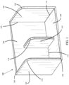
Fig. 1 is a top front left side perspective view of an embodiment of a container storage device. -
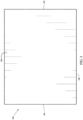
Fig. 2 is a front view of an embodiment of a container storage device. -
Fig. 3 is a rear view of an embodiment of a container storage device. -
Fig. 4 is a left side view of an embodiment of a container storage device. -
Fig. 5 is a right side view of an embodiment of a container storage device. -
Fig. 6 is a top view of an embodiment of a container storage device. -
Fig. 7 is a bottom view of an embodiment of a container storage device. -
Fig. 8 is a top front left side perspective view of three container storage devices side-by-side. -
Fig. 9 is a top front left side perspective view of an embodiment of a container storage device retaining a container. -
Fig. 10 is an illustration depicting exemplary dimensions of an embodiment of the container storage device components. -
Figs. 11A-11B depict utilization of magnets in an embodiment of the storage device. -
Fig. 12 is an illustration of the wood and fabric components of an embodiment of the storage device. -
Fig. 13 is an illustration of and embodiment of three storage devices in a reversibly conjoined state. -
Fig. 14 is an illustration of an embodiment of the storage device retaining two culinary containers. -
Fig. 15 is an illustration of an embodiment of three storage devices, in a reversibly conjoined state, each retaining one or more culinary containers. - In the following detailed description, reference will be made to the accompanying drawing(s), in which identical functional elements are designated with like numerals. The aforementioned accompanying drawings show by way of illustration, and not by way of limitation, specific aspects, and implementations consistent with principles of this disclosure. These implementations are described in sufficient detail to enable those skilled in the art to practice the disclosure and it is to be understood that other implementations may be utilized and that structural changes and/or substitutions of various elements may be made without departing from the scope of the present invention as defined in the appended claims. The following detailed description is, therefore, not to be construed in a limited sense.
- It is noted that the description herein is not intended as an extensive overview, and as such, concepts may be simplified in the interests of clarity and brevity.
- Any process described in this application may be performed in any order and may omit any of the steps in the process. Processes may also be combined with other processes or steps of other processes.
- Aspects of the present disclosure may include at least two
storage devices 100. Each of thestorage devices 100 comprise afirst wall 102, asecond wall 104, arear wall 106, abottom wall 108, and/or adivider 110. Thefirst wall 102, thesecond wall 104, and/or therear wall 106 may be disposed orthogonally to thebottom wall 108. In an embodiment, the storage device may be covered in a covering. In another embodiment, thefirst wall 102, theleft wall 104, and/or therear wall 106 may not be disposed orthogonally to thebottom wall 108. Further, thefirst wall 102 and thesecond wall 104 may be disposed in parallel to one another. Yet further, thefirst wall 102 and thesecond wall 104 may be disposed orthogonally to therear wall 106. Similarly, thedivider 110 may be disposed in parallel to thefirst wall 102 and thesecond wall 104. In an embodiment, thedivider 110 may be disposed orthogonally to therear wall 106 and/orbottom wall 108. - Turning to
FIGS. 1-9 , in an embodiment, a distal end of thesecond wall 104 and a distal end of thefirst wall 102 may attach to a first side of therear wall 106 and/or a second side of therear wall 106. Thesecond wall 104 and thefirst wall 102 may include rounded edges or corners (described herein asleft bullnose 116 and right bullnose 120). In another embodiment, thesecond wall 104 and thefirst wall 102 may include angular edges or corners (i.e., right-angles). As a nonlimiting example, theleft bullnose 116 and/or theright bullnose 120 may be rounded. In such a nonlimiting example, the rounded edges of theleft bullnose 116 and/or theright bullnose 120 may enable unobstructed placement and withdrawal of containers within thestorage device 100. Accordingly, saidbullnoses 116/120 may be less jagged and, thus, less likely to cause snags (as opposed to a sharp ninety-degree corner) when depositing containers within thestorage device 100. - In an embodiment, the
first wall 102 and therear wall 106 meet perpendicularly to form a left-rear juncture 126. In an alternative embodiment, thefirst wall 102 and therear wall 106 do not meet perpendicularly. In a further embodiment, thesecond wall 104 and therear wall 106 meet perpendicularly to form a right-rear juncture 128. In another embodiment, thesecond wall 104 and therear wall 106 do not meet perpendicularly. The left-rear juncture 126 and right-rear juncture 128 may fasten therear wall 106 to thefirst wall 102 and/or thesecond wall 104. In a further embodiment, thefirst wall 102 and thebottom wall 108 may meet to form a left-bottom juncture 130. In such an embodiment, thefirst wall 102 and thebottom wall 108 may meet perpendicularly. In an embodiment, thesecond wall 104 and thebottom wall 108 may meet to form a right-bottom juncture 132. In such an embodiment, thesecond wall 104 and thebottom wall 108 may meet perpendicularly. The left-bottom juncture 130 and the right-bottom juncture 132 may meet to fasten thebottom wall 108 to thefirst wall 102 and/or thefirst wall 104. The left-rear juncture 126, the right-rear juncture 128, the left-bottom juncture 130, and the right-bottom juncture 132 (collectively, the "junctures"), as formed by thefirst wall 102, thesecond wall 104, and the rear wall 106 (collectively, the "walls"), may provide rigid support to thestorage device 100. In yet a further embodiment, therear wall 106 and thebottom wall 108 may meet perpendicularly to form a rear-bottom juncture 134. - In an embodiment, the
divider 110 is disposed on therear wall 106 and/or thebottom wall 108. In a further embodiment, thedivider 110 may be positioned equidistant from thefirst wall 102 and/or thesecond wall 104. In another embodiment, thedivider 110 may be shorter than therear wall 106, thefirst wall 102, and/or thesecond wall 104. As a nonlimiting example, thedivider 110 may be roughly 70% the height of therear wall 106, thefirst wall 102, and/or thesecond wall 104. However, thedivider 110 may be any height equal to or less than the walls. Further, thedivider 110 may be roughly 70% the depth of thefirst wall 102 and/or thesecond wall 104. However, thedivider 110 may be any depth equal to or less than the walls. Thedivider 110 may be sized and adapted to partition the storage device 100 (for example, to provide structure for retention of containers), yet may be unobtrusive enough as to enable withdrawal and deposit of containers within thestorage device 100. - A first pocket 112 is formed between the
first wall 102 and thedivider 110. A second pocket 114 is formed between thedivider 110 and thesecond wall 104. Volumetrically, if thedivider 110 is disposed at the midpoint of therear wall 106, the first pocket 112 and the second pocket 114 may comprise the same volumes. However, the volumes of the first pocket 112, and the second pocket 114, may be adjusted as a function of the position of thedivider 110. Thestorage device 100 may have a total volume comprising at least the first pocket volume and the first pocket volume. - In one embodiment, the first wall height may be equal to the first wall depth and/or the second wall height may be equal to the second wall depth. Thus, with the exception of the bullnoses 114/118, the
first wall 102 and thesecond wall 104 may be generally square. However, in alternate embodiments thefirst wall 102 and thesecond wall 104 may be any suitable dimensions. - Referring to
FIG. 10 , in an embodiment, thestorage device 100 may be 173 mm wide, 137 mm deep, and/or 137 mm tall. In a further embodiment, thefirst wall 102 and/or thesecond wall 104 may be 137 mm tall and/or 137 mm deep. In yet a further embodiment, thedivider 110 may be 90 mm deep and/or 96 mm tall. In another embodiment, thefirst wall 102 and/or thesecond wall 104 may be 5.75 mm thick. In an alternative embodiment, thedivider 110 may be 9 mm thick. However, thefirst wall 102, thesecond wall 104, and thedivider 110, of thestorage device 100, may be any suitable dimensions. - The
storage device 100 further includes one ormore magnets 136. According to the present invention, the one ormore magnets 136 may be embedded in thefirst wall 102 and/or thesecond wall 104, such that saidmagnets 136 may be in line with a plane of thefirst wall 102 and/or thesecond wall 104. As shown inFIGS. 11A-11B , the one ormore magnets 136 are deposited within one ormore magnet wells 138. In an embodiment, the one ormore magnet wells 138 are sized to accept the one ormore magnets 136. Further, the one ormore magnets 136 may be flush with the one ormagnet wells 138. In such an embodiment, the one ormore magnets 136 may be concealed by the covering (i.e., a fabric disposed over the one ormore magnets 136 and the one or more magnet wells 138). In an embodiment, a single magnet may be used. In an alternative embodiment, two or more magnets may be used. In either of the aforementioned embodiments, the one ormore magnets 136 of afirst storage device 100 may magnetically affix to asecond storage device 100. The one ormore magnets 136 may be circular in shape to allow for seamlessness within the magnet well 138. However, the one or more magnets may be any suitable shape. In an embodiment, the one ormore magnets 136 may be a neodymium magnet (for example, a N38 or N52 neodymium magnet). In an embodiment, the one ormore magnets 136 may be multi-pole or polymagnets, for example, to enable increasedavailable storage device 100 orientations because such magnets may not require a specific orientation to adhere. In a further embodiment, the one ormore magnets 136 may have any strength suitable for storing containers and conjoiningstorage devices 100. In an embodiment, magnetic coupling may be achieved by placing afirst wall 102 and/orsecond wall 104 of afirst storage device 100 in close proximity to afirst wall 102 and/orsecond wall 104 of asecond storage device 100. Accordingly, the magnetic attraction between the twodevices 100 may allow the twodevices 100 to reversibly couple. In an alternate embodiment, thefirst wall 102 and/or thesecond wall 104 may include a metallic element configured to induce magnetic coupling between the metallic element and the one ormore magnets 136. In an embodiment, thefirst wall 102 and/or thesecond wall 104 containing the one ormore magnets 136 may be sufficiently thick, such that the one ormore magnets 136 are further distanced from potentially metallic containers stored within thestorage device 100. Such an embodiment may reduce unintentional magnetic adherence of a container to thefirst wall 102 and/or thesecond wall 104. - In an alternate embodiment, one or
more storage devices 100 may be coupled via a hook- and-loop fastener, an adhesive, a button(s), a latch, a locking hinge, or other fastener. In such an embodiment, these alternate fasteners may supplement the one ormore magnets 136. - In an embodiment, the
storage device 100 may include any number of dividers. Further, the dividers may be positioned in any fashion. In an alternate embodiment, any number of the dividers may be positioned at least one of orthogonally, parallelly, and angled to thefirst wall 102 and/or thesecond wall 104. In an embodiment, the dividers may be of a thickness that is equivalent to a thickness of thefirst wall 102 and/or thesecond wall 104. Alternatively, the dividers may be of a thickness that is at least one of greater than and less than thefirst wall 102 and/or thesecond wall 104. Further, the dividers may be at least one of transparent and opaque. - In an embodiment, the
storage device 100 may be comprised of a rigid material. Said rigid material may include, but is not limited to, plastic, wood, cardboard, and/or Medium-Density Fiberboard ("MDF"). In an embodiment, thestorage device 100 or components of thestorage device 100 may include the covering. The covering may be utilized to prevent culinary containers from slipping from and/or scratching adjacent culinary containers. As a nonlimiting example, MDF may be used to construct thestorage device 100, enabling a rigid structure capable of accepting the covering seamlessly. In yet a further embodiment, thestorage device 100 may be comprised of a non-slip bottom. In such an embodiment, the non-slip bottom may prevent thestorage device 100 from slipping while atop a supporting surface. In an alternative embodiment, the non-slip bottom may be disposed upon a bottom surface of thebottom wall 108. - Referring to
FIG. 12 , thestorage device 100 may be composed of a plurality of rigid components (shown above) and a plurality of corresponding covering pieces (shown below), wherein the plurality of rigid components may be comprised of the rigid material. In an embodiment, the plurality of corresponding covering pieces may be sized to cover at least one of the plurality of rigid components. However, at least one of the plurality of corresponding covering pieces may be sized to the plurality of rigid components. In an embodiment, one or more of the plurality of covering pieces may include cut-outs (i.e., sized to accept a divider). In an embodiment, a logo may be printed on at least one of the plurality of corresponding covering pieces, which may cover thefirst wall 102, thesecond wall 104, therear wall 106, and/or thebottom wall 108. In a further embodiment, one ormore magnets 136 may be positioned on thefirst wall 102 and/or thesecond wall 104. As a nonlimiting example, the one ormore magnets 136 may be captured between the rigid material and the covering disposed atop the rigid material. Further, the one ormore magnets 136 may be coupled to the corresponding one ormore magnet wells 138 via an adhesive. In an alternate embodiment, the one ormore magnets 136 may be coupled to the corresponding one ormore magnet wells 138 via a hook and loop fastener. The plurality of corresponding covering pieces may be fastened to the plurality of rigid components via an adhesive. Each rigid component may have a corresponding covering piece. As a nonlimiting example, glue may be applied to an outer perimeter of the plurality of corresponding covering pieces, such that said perimeter may be wrapped around at least one of the plurality of rigid components. Such method of assembly enables the covering pieces to be applied after assembly of the rigid components. In an embodiment, provisions of the plurality of rigid components and the plurality of corresponding covering pieces, as shown inFIG. 12 , may permit thestorage device 100 to maintain the structure described herein. Each of thestorage device 100 components (thefirst wall 102, thesecond wall 104, therear wall 106, thebottom wall 108, and/or the divider 110) may be equipped with one or more covering pieces. The covering pieces may include an overlap when assembled. Such covering pieces and overlap may increase the storage device's 100 water resistance, which is particularly effective for storing containers which have just been washed. - In an embodiment, the covering is waterproof (for example, to promote integrity of the
storage device 100 when wet container items are deposited within or adjacent to the storage device 100). In a further embodiment, the covering may be textured (for example, to promote friction such the containers do not move excessively within the storage device 100). The covering may be at least one of 720D cotton/linen fabric, 1MM, waterproof, and 200-210gsm. In another embodiment, the covering may accommodate a weave pattern for texture. However, the covering may be comprised of any suitable textile alternative. In one embodiment, the covering may be treated with a spray finish, for example, a clear coat finish. Such a spray finish may increase the integrity of thestorage device 100 both structurally and aesthetically (for example, preventing stains or providing a surface that is easier to clean). - The
storage device 100 may be configured in a plurality of sizes. In an embodiment, the plurality of sizes may be able to accommodate small and/or large bundles of culinary containers. In a further embodiment, thestorage device 100 may be sized to fit any combination and/or quantity of a small culinary container with or without a lid, a medium culinary container with or without a lid, a large culinary container with or without a lid, a dot ramekin/insert with or without a lid, and/or a dash ramekin/insert with or without a lid. However, the storage device may be configured to store any suitable culinary storage device alternative. - Referring to
FIG. 13 , a plurality of storage devices may be conjoined. As a nonlimiting example, the rear wall of a first storage device may interface with the rear wall of a second storage device and/or the rear wall of a third storage device may interface with the first wall of the first storage device and the second wall of the second storage device. In some embodiments, one ormore magnets 136 may be disposed in therear wall 106, such that therear wall 106 of astorage device 100 may reversibly couple with thefirst wall 102 and/or a wall of another storage device. In effect, any number of storage devices may be conjoined in any suitable manner. - The
magnet wells 138 are positioned in thefirst wall 102 and/or thesecond wall 104 of the first storage device such that adjacent walls of other storage devices may magnetically couple to the first storage device regardless of orientation. As a further nonlimiting example, themagnet wells 138 may be positioned such that the first wall and/or second wall of the first storage device may magnetically couple to a first wall of the second storage device and/or asecond wall 104 of the second storage device. - In one embodiment, the
divider 110 may adhere to therear wall 106 and/or thebottom wall 108 prior to application of the covering. Accordingly, thedivider 110 may be securely affixed as a function of both an adhesive between thedivider 110 and therear wall 106 and/or thebottom wall 108, and/or the tension and support provided by the covering. In an embodiment, the plurality of corresponding covering pieces may be sized slightly larger than the surface area of an outer face of at least one of thefirst wall 102, thesecond wall 104, therear wall 106, and thebottom wall 108 such that the outer perimeter may wrap around thefirst wall 102, thesecond wall 104, therear wall 106, and/or thebottom wall 108. In such an embodiment, said covering may partially cover the inner surfaces of thefirst wall 102, thesecond wall 104, therear wall 106, and/or thebottom wall 108. Accordingly, one or more segments of the plurality of corresponding covering pieces may be applied to the inner surfaces of thefirst wall 102, thesecond wall 104, therear wall 106, and/or thebottom wall 108 to conceal the outer perimeters of said covering pieces. -
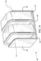
Fig. 14 is an illustration of an embodiment of the storage device retaining two culinary containers. Thestorage device 100 may be configured to retain two equally sized culinary containers. As a nonlimiting example, one of each culinary container may be deposited into the first pocket 112 and/or the second pocket 114. Yet further, thestorage device 100 may be sized to accommodate culinary containers disposed in an upright position (i.e., the one or more culinary containers may stand upon their sidewall). However, the first pocket 112 and/or the second pocket 114 may be sized to accept a culinary container of any suitable dimensions in any suitable orientation. -
Fig. 15 is an illustration of an embodiment of three storage devices, in a reversibly conjoined state, eachstorage device 100 retaining one or more culinary containers. As shown inFig. 15 , a variety of culinary containers may be retained by thestorage device 100. In another embodiment a plurality of storage devices may be conjoined. In an embodiment, a plurality of storage devices 100 (e.g., three) may be conjoined and utilized to create a storage system for a mixed-container set. In another embodiment, the heights of the culinary containers may be equal such that each of the culinary containers may be inserted on their sides into at least one of the first pocket 112 and the second pocket 114. In a further embodiment, the distance between thefirst wall 102 and thedivider 110 and the distance between thedivider 110 and thesecond wall 104 may be similar to the heights of the various containers. As a nonlimiting example, the widths of the inserts may be similar to the heights of the various containers, and thus, similar to the widths of the first pocket 112 and the second pocket 114. In such a nonlimiting example, thestorage device 100 may be configured to receive the inserts in an upright and/or stacked orientation and the various containers in a sideways orientation. All the aforementioned dimensions of eachstorage device 100, and the quantity ofstorage devices 100, may be altered to accommodate containers of different quantities and dimensions. - Various elements, which are described herein in the context of one or more embodiments, may be provided separately or in any suitable subcombination. Further, the processes described herein are not limited to the specific embodiments described. For example, the processes described herein are not limited to the specific processing order described herein and, rather, process blocks may be re-ordered, combined, removed, or performed in parallel or in serial, as necessary, to achieve the results set forth herein.
- It will be further understood that various changes in the details, materials, and arrangements of the parts that have been described and illustrated herein may be made by those skilled in the art without departing from the scope of the following claims.
- Finally, other implementations of the disclosure will be apparent to those skilled in the art from consideration of the specification and practice of the disclosure disclosed herein. It is intended that the specification and examples be considered as exemplary only, with the scope of the invention being defined by the following claims.
Claims (9)
- A culinary container storage system comprising:
at least two storage devices (100) each of the at least two storage devices (100) reversibly attachable, each of the at least two storage devices (100) comprising:a bottom wall (108);a rear wall (106) attached to the bottom wall (108);a first wall (102) attached to both the bottom wall (108) and the rear wall (106);a second wall (104) attached to both the bottom wall (108) and the rear wall (106);a divider (118) attached to both the bottom wall (108) and the rear wall (106), the divider (118) disposed betweenthe first wall (102) and the second wall (104),wherein the divider (118) is shorter and less deep than the first wall (102), the second wall (104), andwherein the divider (118) is shorter than the rear wall (106);a first pocket (110) disposed between the first wall (102) and the divider (118),
the first pocket (112) bound by at least the first wall (102), the rear wall (106), the bottom wall (108), and the divider (118),a second pocket (114) disposed between the second wall (104) and the divider (118),
the second pocket (114) bound by at least the second wall (104), the rear wall (106), the bottom wall (108) and the divider (118);one or more magnet wells (138) disposed within the first wall (102) and the second wall (104); andone or more magnets (136) disposed within the one or more magnet wells (138) of the first wall (102) and the second wall (104). - The culinary container storage system of Claim 1, wherein the rear wall (106), the first wall (102), and the second wall (104) are orthogonal to the bottom wall (108).
- The culinary container storage system of Claim 2, wherein the first wall (102) and the second wall (104) are orthogonal to the rear wall (106).
- The culinary container storage system of any preceding claim, wherein each of the at least two storage devices (100) is comprised of a rigid material.
- The culinary container storage system of Claim 4, wherein the rigid material is medium-density fiberboard.
- The culinary container storage system of any preceding claim, wherein the bottom wall (108), the rear wall (106), the first wall (102), the second wall (104), and the divider (118) attached to both the bottom wall (108) and the rear wall (106) are at least partially covered in a covering.
- The culinary container storage system of Claim 6, wherein the covering is waterproof.
- The culinary container storage system of any preceding claim, wherein the one or magnets (136) are neodymium magnets.
- The culinary container storage system of any preceding claim, wherein the first pocket (112) is defined by a first pocket volume and the second pocket (114) is defined by a second pocket volume, wherein the first pocket volume is equal to the second pocket volume.
Applications Claiming Priority (2)
| Application Number | Priority Date | Filing Date | Title |
|---|---|---|---|
| US202263417985P | 2022-10-20 | 2022-10-20 | |
| US18/487,120 US12220088B2 (en) | 2022-10-20 | 2023-10-16 | Culinary container storage device |
Publications (2)
| Publication Number | Publication Date |
|---|---|
| EP4356799A1 EP4356799A1 (en) | 2024-04-24 |
| EP4356799B1 true EP4356799B1 (en) | 2025-04-23 |
Family
ID=88504766
Family Applications (1)
| Application Number | Title | Priority Date | Filing Date |
|---|---|---|---|
| EP23204605.2A Active EP4356799B1 (en) | 2022-10-20 | 2023-10-19 | Culinary container storage device |
Country Status (3)
| Country | Link |
|---|---|
| US (2) | US12220088B2 (en) |
| EP (1) | EP4356799B1 (en) |
| CA (1) | CA3217069A1 (en) |
Families Citing this family (6)
| Publication number | Priority date | Publication date | Assignee | Title |
|---|---|---|---|---|
| DE202022101171U1 (en) * | 2022-03-03 | 2022-03-30 | Anna Lena Duveneck | Device for hanging harness |
| US12220088B2 (en) * | 2022-10-20 | 2025-02-11 | Caraway Home, Inc. | Culinary container storage device |
| USD1090129S1 (en) * | 2023-09-21 | 2025-08-26 | Caraway Home, Inc. | Storage rack |
| USD1090131S1 (en) * | 2024-03-15 | 2025-08-26 | Caraway Home, Inc. | Cookware storage system |
| US20260097608A1 (en) * | 2024-10-04 | 2026-04-09 | Askoh.Com Llc | Paper tray storage system |
| USD1121352S1 (en) * | 2025-01-03 | 2026-04-07 | Caraway Home, Inc. | Container holder |
Family Cites Families (100)
| Publication number | Priority date | Publication date | Assignee | Title |
|---|---|---|---|---|
| US1479328A (en) * | 1921-11-03 | 1924-01-01 | Joseph C Sinel | Box |
| US2269201A (en) * | 1938-03-15 | 1942-01-06 | Kerk Guild Inc | Transparent container and method of making same |
| US2175753A (en) * | 1938-06-17 | 1939-10-10 | Eugene Y Guthmann | Soap receptacle |
| US2222974A (en) * | 1939-05-22 | 1940-11-26 | Bow Andrew Wilson | Animal display bench |
| US2522483A (en) * | 1946-05-10 | 1950-09-12 | Harry G Plack | Plural soap-cake holder |
| US3187890A (en) * | 1959-07-03 | 1965-06-08 | Sawyers Inc | Projector slide tray |
| US3338421A (en) * | 1965-07-13 | 1967-08-29 | Data Packaging Corp | Tape reel rack |
| US3391793A (en) * | 1965-11-24 | 1968-07-09 | Herbert W. Streuli | Bookrack |
| US3592344A (en) * | 1968-12-26 | 1971-07-13 | Nat Blank Book Co | Collapsible sectional bookcase unit |
| US3827570A (en) * | 1969-06-06 | 1974-08-06 | Browne Co Morse | Paper tray |
| CH530689A (en) * | 1971-02-03 | 1972-11-15 | Gustavsbergs Fabriker Ab | Stand for holding plate-shaped objects |
| US3737046A (en) * | 1971-09-09 | 1973-06-05 | M Jeter | Filing system |
| US3905484A (en) * | 1973-08-20 | 1975-09-16 | Wright Barry Corp | Flexible dividers for lateral shelf filing |
| US3870156A (en) * | 1973-08-20 | 1975-03-11 | Brown Jug Inc | Modular wine bottle rack |
| US4084865A (en) * | 1976-10-26 | 1978-04-18 | Joyce James E | Utility container |
| US4178047A (en) * | 1977-08-17 | 1979-12-11 | Modular Systems, Inc. | Furniture units with concealed fasteners and method therefor |
| US4320837A (en) * | 1978-09-22 | 1982-03-23 | Phillips Petroleum Company | Nesting and stacking container |
| US4331232A (en) * | 1980-02-25 | 1982-05-25 | Larkin Mark E | Soap dish |
| USD267216S (en) * | 1980-07-22 | 1982-12-14 | Swan Milton D | Cassette holder |
| US4396123A (en) * | 1981-04-20 | 1983-08-02 | Swan Milton D | Tape cassette holder |
| USD279245S (en) * | 1982-12-13 | 1985-06-18 | Marylin Wohlman | Purse holder |
| US4494658A (en) * | 1983-07-15 | 1985-01-22 | Thomas A. Schutz Co., Inc. | Modular display for cigarette packs |
| US4595105A (en) * | 1984-09-12 | 1986-06-17 | Gold Kenneth S | Interlocking bookrack |
| USD294665S (en) * | 1985-05-01 | 1988-03-15 | Esselte Pendaflex Corporation | Storage rack |
| US4714165A (en) * | 1985-07-17 | 1987-12-22 | Jack Solomon | Storage rack |
| USD299657S (en) * | 1985-12-09 | 1989-01-31 | Shih-Ming Hwang | File organizer |
| USD300707S (en) * | 1986-04-21 | 1989-04-18 | Walmesley Mark W | Taco holder |
| US4684027A (en) * | 1986-09-25 | 1987-08-04 | Wright Line, Inc. | Stationary storing and dispensing system |
| US4949853A (en) * | 1987-07-13 | 1990-08-21 | Liberty Diversified Industries | Convertible desktop organizer |
| US4848855A (en) * | 1987-07-13 | 1989-07-18 | Buckler Corporation | Accessory storage device having modular construction |
| US4909398A (en) * | 1988-05-28 | 1990-03-20 | Santucci Donald G | Magazine file system |
| US5070645A (en) * | 1989-04-10 | 1991-12-10 | Highland Supply Corporation | Flower pot container |
| US5121681A (en) * | 1991-07-11 | 1992-06-16 | Chang Wen C | Extendible book shelf |
| US5207334A (en) * | 1991-09-26 | 1993-05-04 | Lear John E | Pot lid organizer and storage device |
| USD335976S (en) * | 1991-10-18 | 1993-06-01 | Brown Thomas B | Toolbox drawer organizer |
| US5249724A (en) * | 1992-02-04 | 1993-10-05 | Green Howard T | Underseat storage container |
| US5332106A (en) * | 1992-12-17 | 1994-07-26 | Schlotte Alice M | Spoon and fork holder |
| US5462299A (en) * | 1993-09-02 | 1995-10-31 | Cambro Manufacturing Company | Tray and dish cart |
| EP0752229A1 (en) * | 1995-07-06 | 1997-01-08 | Michael Von Seidel | A soap dish |
| USD381546S (en) * | 1995-08-31 | 1997-07-29 | Hunt Thomas A | Compact disk organizer rack |
| US5593037A (en) * | 1995-09-01 | 1997-01-14 | Ohayon; Abraham | Stackable bins |
| USD382405S (en) * | 1995-09-01 | 1997-08-19 | Aberdeen Plastics Co., Inc. | Stackable bin |
| USD385922S (en) * | 1996-10-23 | 1997-11-04 | Custom Plastics, Inc. | Folder tray |
| US5833334A (en) * | 1997-05-07 | 1998-11-10 | Harper; Dale | Organizer for home entertainment accessories |
| USD396580S (en) * | 1997-05-07 | 1998-08-04 | Dale Harper | Remote control organizer unit |
| US5896698A (en) * | 1997-08-07 | 1999-04-27 | Nurse; Angela | Decorative cover for a plant container |
| USD423299S (en) * | 1998-10-13 | 2000-04-25 | Delores Burrus | Stretchable fabric cover for a container |
| USD422436S (en) * | 1999-06-23 | 2000-04-11 | Fisher Michael W | Shelf |
| USD427835S (en) * | 1999-12-07 | 2000-07-11 | Custom Plastics, Inc. | Disk storage holder |
| US6393749B1 (en) * | 2000-04-20 | 2002-05-28 | Thomas M. Haupt | Napkin/picture holder |
| US20040084448A1 (en) * | 2002-09-11 | 2004-05-06 | Huang Sunny E.L. | Collapsible container for storage |
| US20050023175A1 (en) * | 2003-08-01 | 2005-02-03 | Freelander Robert C. | Stackable wire frame storage bin |
| USD500638S1 (en) * | 2003-10-15 | 2005-01-11 | Each 2 Each, Inc. | Kitchen lid organizer |
| US20050279725A1 (en) * | 2004-06-16 | 2005-12-22 | Sheldon Janice P | Kitchen organizer |
| USD519279S1 (en) * | 2004-08-23 | 2006-04-25 | Gsl Solutions, Inc. | Modular will-call storage device |
| USD522748S1 (en) * | 2004-12-09 | 2006-06-13 | Paecock Apparel Group, Inc. | Fabric covered necktie container |
| US7308987B2 (en) * | 2004-12-22 | 2007-12-18 | Behr Process Corporation | Modular display apparatus |
| US20060255031A1 (en) * | 2005-05-16 | 2006-11-16 | Cartwright Stephanie H | Preparing a decorative container |
| USD547973S1 (en) * | 2005-11-16 | 2007-08-07 | Akro-Mills, Inc. | Systems bin |
| US20070131682A1 (en) * | 2005-12-12 | 2007-06-14 | Fortune Standard Limited | Foldable container |
| US20070181584A1 (en) * | 2006-02-03 | 2007-08-09 | Diane Hoffner | Insulating cover for disposable serving containers and method of using same |
| KR20090007271U (en) | 2008-01-15 | 2009-07-20 | 김대윤 | The folding partition desk for reading room |
| USD651801S1 (en) * | 2011-01-24 | 2012-01-10 | Johnny Brown | Tote |
| USD646722S1 (en) * | 2011-02-08 | 2011-10-11 | Officemate International Corporation | Holder |
| USD720166S1 (en) * | 2011-06-24 | 2014-12-30 | Paul S. Trindall | Boxed wine stand |
| USD673391S1 (en) * | 2012-02-08 | 2013-01-01 | Lisle Corporation | Pliers rack |
| US20140183148A1 (en) * | 2012-12-28 | 2014-07-03 | Allure Home Creation Co., Inc. | Magnetic Cookware Stands |
| US20150037522A1 (en) * | 2013-07-30 | 2015-02-05 | Jerome Smith | Decorative Container Cover Device |
| USD706493S1 (en) * | 2013-10-11 | 2014-06-03 | The Kyjen Company, Inc. | Pet bowl |
| CA2867606A1 (en) * | 2013-10-18 | 2015-04-18 | Kerry J. Kirby | Refuse container cover |
| USD720401S1 (en) * | 2013-11-18 | 2014-12-30 | Officemate International Corp. | Magazine file |
| US20160166117A1 (en) * | 2014-05-21 | 2016-06-16 | Charles Adewale Oduguwa | Cooking Utensil Caddy |
| US9878845B2 (en) * | 2015-07-02 | 2018-01-30 | Sheryl Lynn Thornton | Container cover |
| US11950719B2 (en) * | 2015-11-20 | 2024-04-09 | Stefano SOLCI | Tray covering element |
| US10945563B2 (en) * | 2016-03-21 | 2021-03-16 | Ravi Singh | Cutting board tray |
| USD814216S1 (en) * | 2017-03-31 | 2018-04-03 | Ppg Industries Ohio, Inc. | Display case |
| CN109330222A (en) | 2018-12-14 | 2019-02-15 | 国网山东省电力公司建设公司 | An engineering filing cabinet |
| CN111493709B (en) | 2019-01-31 | 2024-12-24 | 苏州新清松智能科技有限公司 | A cutting board storage device with disinfection and sterilization function |
| US11261006B2 (en) * | 2019-03-13 | 2022-03-01 | Thomas Michael Kennedy | Container organizer |
| WO2021071817A1 (en) * | 2019-10-07 | 2021-04-15 | Caraway Home, Inc. | Cookware storage system |
| USD939286S1 (en) * | 2019-10-11 | 2021-12-28 | Caraway Home, Inc. | Cookware pan racks |
| FR3104927B1 (en) * | 2019-12-20 | 2021-12-03 | Alain Chennaux | Modular and scalable furniture |
| USD941583S1 (en) * | 2020-04-07 | 2022-01-25 | Polder Products, Llc | Organization device |
| USD959084S1 (en) * | 2020-09-01 | 2022-07-26 | Sudham Nilaweera | Drying rack |
| TWD215397S (en) * | 2020-09-10 | 2021-11-21 | 魏行健 | storage box |
| USD1037717S1 (en) * | 2020-12-11 | 2024-08-06 | Brett C. Seager | Low profile compartmentalized trading card storage box |
| US11445822B1 (en) * | 2021-04-28 | 2022-09-20 | United States Marketing Corp. | Expandable modular rack for storing at least one magazine and at least one handgun |
| EP4358812A4 (en) * | 2021-06-22 | 2025-04-23 | Caraway Home, Inc. | BAKED GOODS STORAGE SYSTEM |
| US11484119B1 (en) * | 2021-10-26 | 2022-11-01 | Eosen Llc | Pistol rack |
| USD1038232S1 (en) * | 2022-07-15 | 2024-08-06 | Hangzhou Yinghua Handicraft Co., Ltd | Five file storage rack |
| US12220088B2 (en) * | 2022-10-20 | 2025-02-11 | Caraway Home, Inc. | Culinary container storage device |
| CN117917221A (en) * | 2022-10-20 | 2024-04-23 | 卡尔维家公司 | Cooking container storage |
| USD1044358S1 (en) * | 2022-10-20 | 2024-10-01 | Caraway Home, Inc. | Container holder |
| USD1008650S1 (en) * | 2023-04-09 | 2023-12-26 | Fujian Zhenghe County Boyi Bamboo Industry Co., Ltd. | Organizer box |
| USD1090129S1 (en) * | 2023-09-21 | 2025-08-26 | Caraway Home, Inc. | Storage rack |
| US11925282B2 (en) * | 2023-10-05 | 2024-03-12 | Forum Brands, Llc | Multi-functional cover for tray tables |
| USD1024563S1 (en) * | 2023-12-15 | 2024-04-30 | Shenzhen Yimeiju Household Products Co., Ltd. | Record storage crate |
| USD1037702S1 (en) * | 2024-03-08 | 2024-08-06 | Wouldn't It Be Nice LLC | Soap dish |
| USD1090131S1 (en) * | 2024-03-15 | 2025-08-26 | Caraway Home, Inc. | Cookware storage system |
| USD1121352S1 (en) * | 2025-01-03 | 2026-04-07 | Caraway Home, Inc. | Container holder |
-
2023
- 2023-10-16 US US18/487,120 patent/US12220088B2/en active Active
- 2023-10-19 EP EP23204605.2A patent/EP4356799B1/en active Active
- 2023-10-19 CA CA3217069A patent/CA3217069A1/en active Pending
-
2025
- 2025-01-31 US US19/042,932 patent/US20250176765A1/en active Pending
Also Published As
| Publication number | Publication date |
|---|---|
| EP4356799A1 (en) | 2024-04-24 |
| US20240225371A9 (en) | 2024-07-11 |
| US20250176765A1 (en) | 2025-06-05 |
| US20240130572A1 (en) | 2024-04-25 |
| US12220088B2 (en) | 2025-02-11 |
| CA3217069A1 (en) | 2024-04-20 |
Similar Documents
| Publication | Publication Date | Title |
|---|---|---|
| US12220088B2 (en) | Culinary container storage device | |
| EP4041032B1 (en) | Cookware storage system | |
| US12384599B2 (en) | Bakeware storage system | |
| US20120262043A1 (en) | Ready-to-assemble space organizer kit and methods for using and manufacturing the same | |
| US8640889B2 (en) | Utility storage rack | |
| WO2024112446A1 (en) | Fishing tackle storage system and method | |
| CN117917221A (en) | Cooking container storage | |
| JP2004167112A (en) | Stacked lunch box set fixed to the mobile frame with chopsticks | |
| CA3153812C (en) | Cookware storage system | |
| US20250235053A1 (en) | Modular culinary equipment storage system | |
| TWI465632B (en) | Opening preventing device for storage box/cabinet | |
| KR200376576Y1 (en) | A wicker basket for acceptance loading type a property | |
| TWM589694U (en) | Storage Box | |
| KR200415144Y1 (en) | Slim box | |
| US9706837B2 (en) | Compact folded garment storage display and dispensing device | |
| CN222982938U (en) | Storage rack for kitchen | |
| JPH092476A (en) | basket | |
| CN212373889U (en) | Combined lifting basket | |
| JPH052114Y2 (en) | ||
| CN204541388U (en) | Stackable type rack | |
| KR930000581Y1 (en) | Stacked basket | |
| JPH0130906Y2 (en) | ||
| CN2413566Y (en) | Storage cabinet hoisting connection device | |
| CN201523833U (en) | Kitchen showcase | |
| CN2274015Y (en) | Cabinet for kitchenware |
Legal Events
| Date | Code | Title | Description |
|---|---|---|---|
| PUAI | Public reference made under article 153(3) epc to a published international application that has entered the european phase |
Free format text: ORIGINAL CODE: 0009012 |
|
| STAA | Information on the status of an ep patent application or granted ep patent |
Free format text: STATUS: THE APPLICATION HAS BEEN PUBLISHED |
|
| AK | Designated contracting states |
Kind code of ref document: A1 Designated state(s): AL AT BE BG CH CY CZ DE DK EE ES FI FR GB GR HR HU IE IS IT LI LT LU LV MC ME MK MT NL NO PL PT RO RS SE SI SK SM TR |
|
| STAA | Information on the status of an ep patent application or granted ep patent |
Free format text: STATUS: REQUEST FOR EXAMINATION WAS MADE |
|
| 17P | Request for examination filed |
Effective date: 20241004 |
|
| RBV | Designated contracting states (corrected) |
Designated state(s): AL AT BE BG CH CY CZ DE DK EE ES FI FR GB GR HR HU IE IS IT LI LT LU LV MC ME MK MT NL NO PL PT RO RS SE SI SK SM TR |
|
| GRAP | Despatch of communication of intention to grant a patent |
Free format text: ORIGINAL CODE: EPIDOSNIGR1 |
|
| STAA | Information on the status of an ep patent application or granted ep patent |
Free format text: STATUS: GRANT OF PATENT IS INTENDED |
|
| INTG | Intention to grant announced |
Effective date: 20241115 |
|
| GRAS | Grant fee paid |
Free format text: ORIGINAL CODE: EPIDOSNIGR3 |
|
| GRAA | (expected) grant |
Free format text: ORIGINAL CODE: 0009210 |
|
| STAA | Information on the status of an ep patent application or granted ep patent |
Free format text: STATUS: THE PATENT HAS BEEN GRANTED |
|
| AK | Designated contracting states |
Kind code of ref document: B1 Designated state(s): AL AT BE BG CH CY CZ DE DK EE ES FI FR GB GR HR HU IE IS IT LI LT LU LV MC ME MK MT NL NO PL PT RO RS SE SI SK SM TR |
|
| REG | Reference to a national code |
Ref country code: GB Ref legal event code: FG4D |
|
| REG | Reference to a national code |
Ref country code: CH Ref legal event code: EP |
|
| REG | Reference to a national code |
Ref country code: DE Ref legal event code: R096 Ref document number: 602023003073 Country of ref document: DE |
|
| REG | Reference to a national code |
Ref country code: IE Ref legal event code: FG4D |
|
| REG | Reference to a national code |
Ref country code: NL Ref legal event code: MP Effective date: 20250423 |
|
| PG25 | Lapsed in a contracting state [announced via postgrant information from national office to epo] |
Ref country code: NL Free format text: LAPSE BECAUSE OF FAILURE TO SUBMIT A TRANSLATION OF THE DESCRIPTION OR TO PAY THE FEE WITHIN THE PRESCRIBED TIME-LIMIT Effective date: 20250423 |
|
| REG | Reference to a national code |
Ref country code: AT Ref legal event code: MK05 Ref document number: 1786921 Country of ref document: AT Kind code of ref document: T Effective date: 20250423 |
|
| PG25 | Lapsed in a contracting state [announced via postgrant information from national office to epo] |
Ref country code: FI Free format text: LAPSE BECAUSE OF FAILURE TO SUBMIT A TRANSLATION OF THE DESCRIPTION OR TO PAY THE FEE WITHIN THE PRESCRIBED TIME-LIMIT Effective date: 20250423 Ref country code: PT Free format text: LAPSE BECAUSE OF FAILURE TO SUBMIT A TRANSLATION OF THE DESCRIPTION OR TO PAY THE FEE WITHIN THE PRESCRIBED TIME-LIMIT Effective date: 20250825 Ref country code: ES Free format text: LAPSE BECAUSE OF FAILURE TO SUBMIT A TRANSLATION OF THE DESCRIPTION OR TO PAY THE FEE WITHIN THE PRESCRIBED TIME-LIMIT Effective date: 20250423 |
|
| REG | Reference to a national code |
Ref country code: LT Ref legal event code: MG9D |
|
| PG25 | Lapsed in a contracting state [announced via postgrant information from national office to epo] |
Ref country code: NO Free format text: LAPSE BECAUSE OF FAILURE TO SUBMIT A TRANSLATION OF THE DESCRIPTION OR TO PAY THE FEE WITHIN THE PRESCRIBED TIME-LIMIT Effective date: 20250723 Ref country code: GR Free format text: LAPSE BECAUSE OF FAILURE TO SUBMIT A TRANSLATION OF THE DESCRIPTION OR TO PAY THE FEE WITHIN THE PRESCRIBED TIME-LIMIT Effective date: 20250724 |
|
| PG25 | Lapsed in a contracting state [announced via postgrant information from national office to epo] |
Ref country code: PL Free format text: LAPSE BECAUSE OF FAILURE TO SUBMIT A TRANSLATION OF THE DESCRIPTION OR TO PAY THE FEE WITHIN THE PRESCRIBED TIME-LIMIT Effective date: 20250423 |
|
| PG25 | Lapsed in a contracting state [announced via postgrant information from national office to epo] |
Ref country code: BG Free format text: LAPSE BECAUSE OF FAILURE TO SUBMIT A TRANSLATION OF THE DESCRIPTION OR TO PAY THE FEE WITHIN THE PRESCRIBED TIME-LIMIT Effective date: 20250423 |
|
| PG25 | Lapsed in a contracting state [announced via postgrant information from national office to epo] |
Ref country code: HR Free format text: LAPSE BECAUSE OF FAILURE TO SUBMIT A TRANSLATION OF THE DESCRIPTION OR TO PAY THE FEE WITHIN THE PRESCRIBED TIME-LIMIT Effective date: 20250423 |
|
| PG25 | Lapsed in a contracting state [announced via postgrant information from national office to epo] |
Ref country code: AT Free format text: LAPSE BECAUSE OF FAILURE TO SUBMIT A TRANSLATION OF THE DESCRIPTION OR TO PAY THE FEE WITHIN THE PRESCRIBED TIME-LIMIT Effective date: 20250423 |
|
| PG25 | Lapsed in a contracting state [announced via postgrant information from national office to epo] |
Ref country code: RS Free format text: LAPSE BECAUSE OF FAILURE TO SUBMIT A TRANSLATION OF THE DESCRIPTION OR TO PAY THE FEE WITHIN THE PRESCRIBED TIME-LIMIT Effective date: 20250723 |
|
| PG25 | Lapsed in a contracting state [announced via postgrant information from national office to epo] |
Ref country code: IS Free format text: LAPSE BECAUSE OF FAILURE TO SUBMIT A TRANSLATION OF THE DESCRIPTION OR TO PAY THE FEE WITHIN THE PRESCRIBED TIME-LIMIT Effective date: 20250823 |
|
| PG25 | Lapsed in a contracting state [announced via postgrant information from national office to epo] |
Ref country code: LV Free format text: LAPSE BECAUSE OF FAILURE TO SUBMIT A TRANSLATION OF THE DESCRIPTION OR TO PAY THE FEE WITHIN THE PRESCRIBED TIME-LIMIT Effective date: 20250423 |
|
| PGFP | Annual fee paid to national office [announced via postgrant information from national office to epo] |
Ref country code: DE Payment date: 20251126 Year of fee payment: 3 |
|
| PG25 | Lapsed in a contracting state [announced via postgrant information from national office to epo] |
Ref country code: SM Free format text: LAPSE BECAUSE OF FAILURE TO SUBMIT A TRANSLATION OF THE DESCRIPTION OR TO PAY THE FEE WITHIN THE PRESCRIBED TIME-LIMIT Effective date: 20250423 Ref country code: DK Free format text: LAPSE BECAUSE OF FAILURE TO SUBMIT A TRANSLATION OF THE DESCRIPTION OR TO PAY THE FEE WITHIN THE PRESCRIBED TIME-LIMIT Effective date: 20250423 |
|
| PGFP | Annual fee paid to national office [announced via postgrant information from national office to epo] |
Ref country code: IT Payment date: 20251031 Year of fee payment: 3 |
|
| PGFP | Annual fee paid to national office [announced via postgrant information from national office to epo] |
Ref country code: FR Payment date: 20251030 Year of fee payment: 3 |
|
| PG25 | Lapsed in a contracting state [announced via postgrant information from national office to epo] |
Ref country code: CZ Free format text: LAPSE BECAUSE OF FAILURE TO SUBMIT A TRANSLATION OF THE DESCRIPTION OR TO PAY THE FEE WITHIN THE PRESCRIBED TIME-LIMIT Effective date: 20250423 |
|
| PG25 | Lapsed in a contracting state [announced via postgrant information from national office to epo] |
Ref country code: EE Free format text: LAPSE BECAUSE OF FAILURE TO SUBMIT A TRANSLATION OF THE DESCRIPTION OR TO PAY THE FEE WITHIN THE PRESCRIBED TIME-LIMIT Effective date: 20250423 |
|
| REG | Reference to a national code |
Ref country code: DE Ref legal event code: R097 Ref document number: 602023003073 Country of ref document: DE |
|
| PG25 | Lapsed in a contracting state [announced via postgrant information from national office to epo] |
Ref country code: SK Free format text: LAPSE BECAUSE OF FAILURE TO SUBMIT A TRANSLATION OF THE DESCRIPTION OR TO PAY THE FEE WITHIN THE PRESCRIBED TIME-LIMIT Effective date: 20250423 |
|
| PLBE | No opposition filed within time limit |
Free format text: ORIGINAL CODE: 0009261 |
|
| STAA | Information on the status of an ep patent application or granted ep patent |
Free format text: STATUS: NO OPPOSITION FILED WITHIN TIME LIMIT |
|
| REG | Reference to a national code |
Ref country code: CH Ref legal event code: L10 Free format text: ST27 STATUS EVENT CODE: U-0-0-L10-L00 (AS PROVIDED BY THE NATIONAL OFFICE) Effective date: 20260304 |
|
| PG25 | Lapsed in a contracting state [announced via postgrant information from national office to epo] |
Ref country code: RO Free format text: LAPSE BECAUSE OF FAILURE TO SUBMIT A TRANSLATION OF THE DESCRIPTION OR TO PAY THE FEE WITHIN THE PRESCRIBED TIME-LIMIT Effective date: 20250423 |
|
| 26N | No opposition filed |
Effective date: 20260126 |