EP4356015B1 - Hinge with internal on-axis rotational stop and shearing mechanisms - Google Patents
Hinge with internal on-axis rotational stop and shearing mechanisms Download PDFInfo
- Publication number
- EP4356015B1 EP4356015B1 EP22729374.3A EP22729374A EP4356015B1 EP 4356015 B1 EP4356015 B1 EP 4356015B1 EP 22729374 A EP22729374 A EP 22729374A EP 4356015 B1 EP4356015 B1 EP 4356015B1
- Authority
- EP
- European Patent Office
- Prior art keywords
- hinge
- region
- axis member
- cover
- stopping feature
- Prior art date
- Legal status (The legal status is an assumption and is not a legal conclusion. Google has not performed a legal analysis and makes no representation as to the accuracy of the status listed.)
- Active
Links
Images


Classifications
-
- B—PERFORMING OPERATIONS; TRANSPORTING
- B64—AIRCRAFT; AVIATION; COSMONAUTICS
- B64C—AEROPLANES; HELICOPTERS
- B64C7/00—Structures or fairings not otherwise provided for
-
- F—MECHANICAL ENGINEERING; LIGHTING; HEATING; WEAPONS; BLASTING
- F16—ENGINEERING ELEMENTS AND UNITS; GENERAL MEASURES FOR PRODUCING AND MAINTAINING EFFECTIVE FUNCTIONING OF MACHINES OR INSTALLATIONS; THERMAL INSULATION IN GENERAL
- F16C—SHAFTS; FLEXIBLE SHAFTS; ELEMENTS OR CRANKSHAFT MECHANISMS; ROTARY BODIES OTHER THAN GEARING ELEMENTS; BEARINGS
- F16C11/00—Pivots; Pivotal connections
- F16C11/04—Pivotal connections
- F16C11/10—Arrangements for locking
-
- B—PERFORMING OPERATIONS; TRANSPORTING
- B64—AIRCRAFT; AVIATION; COSMONAUTICS
- B64G—COSMONAUTICS; VEHICLES OR EQUIPMENT THEREFOR
- B64G1/00—Cosmonautic vehicles
- B64G1/22—Parts of, or equipment specially adapted for fitting in or to, cosmonautic vehicles
- B64G1/64—Systems for coupling or separating cosmonautic vehicles or parts thereof, e.g. docking arrangements
-
- F—MECHANICAL ENGINEERING; LIGHTING; HEATING; WEAPONS; BLASTING
- F16—ENGINEERING ELEMENTS AND UNITS; GENERAL MEASURES FOR PRODUCING AND MAINTAINING EFFECTIVE FUNCTIONING OF MACHINES OR INSTALLATIONS; THERMAL INSULATION IN GENERAL
- F16C—SHAFTS; FLEXIBLE SHAFTS; ELEMENTS OR CRANKSHAFT MECHANISMS; ROTARY BODIES OTHER THAN GEARING ELEMENTS; BEARINGS
- F16C11/00—Pivots; Pivotal connections
- F16C11/04—Pivotal connections
- F16C11/045—Pivotal connections with at least a pair of arms pivoting relatively to at least one other arm, all arms being mounted on one pin
-
- F—MECHANICAL ENGINEERING; LIGHTING; HEATING; WEAPONS; BLASTING
- F16—ENGINEERING ELEMENTS AND UNITS; GENERAL MEASURES FOR PRODUCING AND MAINTAINING EFFECTIVE FUNCTIONING OF MACHINES OR INSTALLATIONS; THERMAL INSULATION IN GENERAL
- F16C—SHAFTS; FLEXIBLE SHAFTS; ELEMENTS OR CRANKSHAFT MECHANISMS; ROTARY BODIES OTHER THAN GEARING ELEMENTS; BEARINGS
- F16C11/00—Pivots; Pivotal connections
- F16C11/04—Pivotal connections
- F16C11/12—Pivotal connections incorporating flexible connections, e.g. leaf springs
-
- F—MECHANICAL ENGINEERING; LIGHTING; HEATING; WEAPONS; BLASTING
- F42—AMMUNITION; BLASTING
- F42B—EXPLOSIVE CHARGES, e.g. FOR BLASTING, FIREWORKS, AMMUNITION
- F42B15/00—Self-propelled projectiles or missiles, e.g. rockets; Guided missiles
- F42B15/34—Protection against overheating or radiation, e.g. heat shields; Additional cooling arrangements
-
- F—MECHANICAL ENGINEERING; LIGHTING; HEATING; WEAPONS; BLASTING
- F42—AMMUNITION; BLASTING
- F42B—EXPLOSIVE CHARGES, e.g. FOR BLASTING, FIREWORKS, AMMUNITION
- F42B15/00—Self-propelled projectiles or missiles, e.g. rockets; Guided missiles
- F42B15/36—Means for interconnecting rocket-motor and body section; Multi-stage connectors; Disconnecting means
-
- Y—GENERAL TAGGING OF NEW TECHNOLOGICAL DEVELOPMENTS; GENERAL TAGGING OF CROSS-SECTIONAL TECHNOLOGIES SPANNING OVER SEVERAL SECTIONS OF THE IPC; TECHNICAL SUBJECTS COVERED BY FORMER USPC CROSS-REFERENCE ART COLLECTIONS [XRACs] AND DIGESTS
- Y10—TECHNICAL SUBJECTS COVERED BY FORMER USPC
- Y10T—TECHNICAL SUBJECTS COVERED BY FORMER US CLASSIFICATION
- Y10T403/00—Joints and connections
- Y10T403/32—Articulated members
- Y10T403/32549—Articulated members including limit means
- Y10T403/32557—Articulated members including limit means for pivotal motion
- Y10T403/32591—Opposed stops on one member
Definitions
- This invention relates to hinges, and more particularly to hinges whose angle of rotation is limited and at which point the hinge shears and breaks detaching the solid object attached to one side of the hinge.
- Such hinges may, for example, be used for the controlled deployment and detachment of a cover on an aerodynamic body such as a missile, rocket, artillery shell, airplane, unmanned aerial vehicle (UAV) or drone or space based system or other moving or stationary bodies or for the controlled detachment of any solid object so attached.
- UAV unmanned aerial vehicle
- Hinges may be defined as a mechanical bearing that connects two solid objects, typically allowing only a limited angle of rotation between them. Two objects connected by an ideal hinge rotate relative to each other about a fixed axis of rotation, all other translations or rotations being prevented, and thus a hinge has one degree of freedom. The angle of rotation is typically limited by an external stop that impedes the rotation of one of the solid objects, the other solid object typically being fixed.
- Certain aerodynamic bodies include elements such as optical windows or domes, air inlets etc. that need to be protected prior to flight, at launch or for some portion of flight before the elements are operational.
- a cover may be secured to the aerodynamic body to protect the element. At launch or later in flight, the cover is released.
- These systems typically use the aerodynamic forces caused by airflow into the body that produces forces radially outward on the cover to deploy and release the cover. In some cases, this occurs immediately after launch. In other cases, a mechanism secures the cover until it is released allowing the airflow to deploy the cover.
- U.S. Patent No. 6,679,453 entitled "Jettisonable Protective Element” discloses a number of embodiments in which a detachable hinge is configured to control the deployment of a cover from an aerodynamic body.
- the hinge 26 can be of an asymmetric ball in socket configuration.
- the ball element frees from the socket, thus enabling spontaneous disassembly of the hinge and detachment of the cover.
- Such a ball and socket hinge may have reliability issues related to either thermal heating, corrosion or manufacturing tolerances.
- the socket remains after detachment and may create localized hot spots or disturbances of the boundary layer of airflow over the aerodynamic body.
- FIGS. 4a -4e and described at col. 8, lines 10 to 41 another embodiment of a hinge breaks at a structurally weakened region formed in the cover when the cover strikes a stoppage element positioned on the aerodynamic body.
- FIG. 5 and described at col. 8, line 62 to col. 9, line 2 another embodiment of a hinge breaks at shearable pin along the rotation axis of the hinge when the cover strikes the stoppage element positioned on the aerodynamic body.
- the stoppage elements that limit the angle of rotation are positioned external to the hinge and offset from the axis of rotation. The load is transferred into cantilevered bending and dumped into the structurally weakened region (e.g., the slit of shearable pin) to shear off the cover.
- the present invention relates to a hinge in which internal on-axis stopping mechanisms cause the hinge to shear and break at an on-axis weakened region of the hinge when rotation of the hinge reaches a predetermined angle with a specified torsional load.
- the on-axis configuration is compact, has minimal impact on the OML of the object to which it is mounted both pre and post detachment and allows for accurate tailoring of the load that will detach the hinge.
- a hinge comprises first and second hinge plates configured for attachment to first and second solid objects, respectively.
- An on-axis member extends from the first hinge plate along an axis of rotation into a thru hole in the second hinge plate.
- a force exerted on the second solid object rotates the second solid object around the axis of rotation.
- the on-axis member includes a stopping feature and a weakened region positioned between the first hinge plate and the stopping feature.
- the second hinge plate includes a complementary stopping feature configured in the thru hole to engage the on-axis member's stopping feature at a predetermined angle of rotation to produce a torsional load on the on-axis member that creates torsional shear of the on-axis member at the weakened region to detach the hinge and remove the second solid object from the first solid object.
- the weakened region may, for example, constitute a smaller diameter region of the member, a slit or aperture formed in the member or with varying material properties.
- the second solid object may be a cover that is permanently detached to uncover a previously covered area.
- the covered area may include a protected element within the first solid object.
- a protected element within the first solid object.
- aerodynamic bodies such as missiles, rockets, guided artillery shells, UAVs, drones, manned aircraft or spacecraft may include protected elements such as optical sensing systems, air inlets or the like that must be protected in flight until those elements are operational.
- a cover is reversibly secured to an aerodynamic body to protect a protected element from an external environment.
- a releasing mechanism e.g., a pyrotechnic or piston actuator
- a securing assembly secures the cover to the aerodynamic body.
- the securing assembly includes the hinge for connecting a first end of the cover to a first region of the aerodynamic body with a releasable element (e.g., tension screws, bands or other mechanically connected element) securing a second end of the cover to a second region of the aerodynamic body.
- the hinge is configured such that when the second end of the cover separates from the second region of the aerodynamic body in flight, a force (e.g., airflow or as provided by the releasing mechanism) exerted on the cover rotates the cover about an axis of rotation to engage the hinge's internal complementary stopping features at a predetermined angle thereby producing a torsional load that shears the hinge at the on-axis weakened region to release the cover.
- a force e.g., airflow or as provided by the releasing mechanism
- the hinge is compact and provides minimal impact on the OML of the aerodynamic body either pre or post-detachment.
- the hinge may be designed in different ways reflecting varying degrees of integration of its component elements and with the solid objects to which it is attached. Different configurations may be selected and possibly combined depending upon the application.
- the stopping feature is a discrete component fastened to the end of the on-axis member (e.g. via a fastener).
- the hinge includes a load transfer interface (e.g., a plurality of shear pins or a splined interface) that couples the stopping feature to the on-axis member to transfer the torsional load created by the engagement of the stopping features to the on-axis member to shear the on-axis member at the weakened region.
- the discrete component may include a full diameter region equal to the diameter of the thru hole in rotational engagement with the thru hole at the load transfer interface.
- the on-axis member may include an integrally formed full diameter region, adjacent the weakened region, which is coupled to the full diameter region of the discrete component via the load transfer interface.
- first and second hinge plates are integrally formed with the first and second solid objects, respectively.
- At least the weakened region of the on-axis member may be integrally formed with the first hinge plate and first solid object.
- the entire on-axis member may be integrally formed with the first hinge plate and first solid object.
- the on-axis member is integrally formed to include the weakened region and the stopping feature.
- the torsional load created by the engagement of the complementary stopping features is applied directly to the weakened region.
- the on-axis member integrally formed or discretely joined, may include a full diameter region equal to the diameter of the thru hole in rotational engagement with the thru hole.
- the stopping feature is offset axially from the full diameter region to engage the complementary stopping feature.
- the stopping feature is formed in the full diameter region to engage the complementary stopping feature.
- the present invention provides a hinge in which internal on-axis stopping mechanisms cause the hinge to shear and break at an on-axis weakened region of the hinge when rotation of the hinge reaches a predetermined angle with a specified torsional load.
- the on-axis configuration is compact, has minimal impact on the OML of the object to which it is mounted both pre and post detachment and allows for accurate tailoring of the load that will detach the hinge.
- a hinge comprises first and second hinge plates configured for attachment to first and second solid objects, respectively.
- An on-axis member extends from the first hinge plate along an axis of rotation into a thru hole in the second hinge plate.
- a force exerted on the second solid object rotates the second solid object around the axis of rotation.
- the on-axis member includes a stopping feature and a weakened region positioned between the first hinge plate and the stopping feature.
- the second hinge plate includes a complementary stopping feature configured in the thru hole to engage the on-axis member's stopping feature at a predetermined angle of rotation to produce a torsional load on the on-axis member that creates torsional shear of the on-axis member at the weakened region to detach the hinge and remove the second solid object from the first solid object.
- the weakened region may, for example, constitute a smaller diameter region of the member, a slit or aperture formed in the member or varying material properties.
- the second solid object may be a cover that is permanently detached to uncover a previously covered area.
- the covered area may include a protected element within the first solid object.
- aerodynamic bodies such as missiles, rockets, guided artillery shells, UAVs, drones, manned aircraft or spacecraft may include protected elements such as optical sensing systems, air inlets or the like that must be protected in flight until those elements are operational.
- a cover is reversibly secured to an aerodynamic body to protect a protected element from an external environment.
- a releasing mechanism e.g., a pyro technic or piston actuator for controlled release or springloaded or airflow for release at launch
- a securing assembly secures the cover to the aerodynamic body.
- the securing assembly includes the hinge for connecting a first end of the cover to a first region of the aerodynamic body with a releasable element (e.g., tension screws, bands or other mechanically connected element) securing a second end of the cover to a second region of the aerodynamic body.
- the hinge is configured such that when the second end of the cover separates from the second region of the aerodynamic body in flight, a force (e.g., airflow or as provided by the releasing mechanism) exerted on the cover rotates the cover about an axis of rotation to engage the hinge's internal complementary stopping features at a predetermined angle thereby producing a torsional load that shears the hinge at the on-axis weakened region to release the cover.
- a force e.g., airflow or as provided by the releasing mechanism
- the hinge is compact and provides minimal impact on the OML of the aerodynamic body either pre or post-detachment.
- the hinge may be designed in different ways reflecting varying degrees of integration of its component elements and with the solid objects to which it is attached. Different configurations may be selected and possibly combined depending upon the application. Without loss of generality, a hinge 10 using discrete components to secure and then controllably detach a cover 12 from a missile 14 will be presented with reference to Figures 1A-1B , 2A-2C , 3A-3B , 4A-4B and 5A-5B .
- Missile 14 includes an aerodynamic body 16, a protected element 18 within the aerodynamic body and cover 12, reversibly secured to the aerodynamic body, for protecting the protected element from an external environment.
- a releasing mechanism 20 such as a pyrotechnic actuator or a piston actuator is configured to at least partially detach the cover from the aerodynamic body.
- a securing assembly 22 secures the cover to the aerodynamic body.
- the securing assembly 22 includes the hinge 10 for connecting a first end 24 of the cover to a first region 26 of the aerodynamic body, and a releasable element 28 such as tension screws, bands or other mechanically connected element securing a second end 30 of the cover to a second region 32 of the aerodynamic body.
- Hinge 10 is configured such that when the second end 30 of the cover separates from the second region 32 of the aerodynamic body when the missile is in flight, a force 34 exerted on the cover rotates the cover about an axis of rotation 36 before detaching the hinge 10, thereby removing the cover 12 from missile 14.
- Force 34 may, for example, be provided by the releasing mechanism 20 or by airflow over the aerodynamic body.
- hinge 10 includes a first hinge plate 40 attached to the aerodynamic body 16.
- An on-axis member 42 extends from the first hinge plate 40 along the axis of rotation 36 aligned with a first thru hole 44 in cover 12.
- the on-axis member includes a full diameter region 46 equal in diameter to the first thru hole 44 in the cover and a reduced diameter weakened region 48 positioned between the first hinge plate 40 and the full diameter region 46.
- a hard stop 50 includes a full diameter region 52 fastened to the end of the full diameter region 46 of the on-axis member via a fastener 53 and a stopping feature 54. Full diameter region 52 is in rotational engagement with the first thru hole 44 in the cover such that the force 34 rotates the cover around the axis of rotation.
- the fastener 53 that fastens the hard stop to the on-axis member has minimal affect on load transfer, its purpose is to secure the hard stop to the on-axis member.
- a second hinge plate 58 is positioned in a recess 60 in cover 12 and attached (clamped) to the cover via fasteners 62 that engage a ring assembly 64 positioned on the inner surface of the cover opposite the second hinge plate.
- Ring assembly 64 includes a floating nut plate 66 that is attached to a ring 68 via fasteners 70.
- Second hinge plate 58 has a second thru hole 72 aligned to the first thru hole 44.
- the second hinge plate has a complementary stopping feature 74 configured in the second thru hole 72 to engage the hard stop's stopping feature 54 at a predetermined angle of rotation to produce moment 76 about the axis of rotation 36 to transfer a torsional load 78 thru the load transfer interface 56 to shear the on-axis member 42 at the reduced diameter weakened region 48 to detach the hinge 10 and remove the cover 12 from the aerodynamic body 16 leaving the first hinge plate 40 and a small proturbance 80 (what remains of the weakened region 48 ) attached to the aerodynamic body.
- hinge 10 is assembled to attach cover 12 to aerodynamic body 16 by attaching the first hinge plates 40 to the aerodynamic body.
- Ring assembly 64 is placed on the on-axis member 42 that extends from the first hinge plates along the axis of rotation.
- Cover 12 is positioned to align thru hole 44 with the on-axis member 42 and axis of rotation 36 as shown in FIG. 2A .
- the second hinge plate 58 is placed in recess 60 and fasteners 70 are inserted through the second hinge plate to engage ring assembly 64 to clamp the second hinge plate 58 to cover 12 as shown in FIG. 2B .
- hard stop 50 is coupled to on-axis member 42 via shear pins 56 and fastener 53 between its full diameter region 52 and the on-axis member full diameter region 46 as shown in FIG. 2C .
- hinge 10 is engaged in flight to controllably release and permanently detach cover 12.
- hinge 10 and cover 12 are secured in a closed or stowed position at 0° of rotation.
- the second end 30 of the cover is secured to the second region 32 of the aerodynamic body 16 to protect the protected element 18 (e.g. an air intake).
- the cover's complementary stopping feature 74 does not engage the hard stop 50.
- the releasing mechanism (pyrotechnic actuator) 20 has separated the releasable elements 28 (tension screws) to partially detach cover 12 from aerodynamic body 16.
- a first hinge plate 102 and a portion of an on-axis member 104 including a reduced diameter weakened region 106 and a full diameter region 108 are integrally formed with the aerodynamic body and a second hinge plate 112 including a complementary stopping feature 114 is integrally formed in a thru hole 116 in a cover 117.
- cover 117 is positioned to align thru hole 116 with on-axis member 104 whose full diameter region 108 nearly contacts the inner surface of the cover.
- a hard stop 118 is attached is attached to on-axis member 104 via fastener 119.
- the load transfer interface is implemented with a splined interface 115 formed on the opposing surfaces of the on-axis member 104 and the hard stop 118.
- an on-axis member 122 is integrally formed to include a reduced diameter weakened region 124, a full diameter region 126 and a stopping feature 128.
- a thru hole 130 in a cover 132 is aligned to a mounting feature 134 on the aerodynamic body.
- the on-axis member 122 is inserted in the through hole to engage mounting feature 134.
- a complementary stopping feature 136 may be formed either in a hinge plate attached to cover 132 or integrally in thru hole 130 in the cover as shown in the drawing.
- An integrally formed on-axis member does not require a load transfer interface to transfer the torsional load produced by engagement of the complementary stopping features to the reduced diameter weakened region.
- the on-axis hinge includes both a full diameter region in rotational engagement with a thru hole in the cover/hinge plate to provide reliable and stable rotation of the cover about the axis of rotation away from the aerodynamic body and complementary stopping features formed on the on-axis member and in the thru hole that engage at a predetermined angle and shear the hinge to permanently detach the cover.
- the complementary stopping features are physically offset axially from the full diameter region of the on-axis member and the thru hole and functionally separately.
- the complementary stopping features may be incorporated into the full diameter region of the on-axis member and the thru hole.
- an on-axis member 142 includes a reduced diameter weakened region 144 and a full diameter region 146.
- a hard stop 148 is coupled to the on-axis member via shear pins 150 and fastener 152.
- Hard stop 148 includes a full diameter region 154 in which a quadrant has been removed to form a stopping feature 156.
- a complementary stopping feature 158 is formed in a wall of a full diameter thru hole 160 to engage stopping feature 156 at a predetermined angle.
Landscapes
- Engineering & Computer Science (AREA)
- General Engineering & Computer Science (AREA)
- Aviation & Aerospace Engineering (AREA)
- Mechanical Engineering (AREA)
- Chemical & Material Sciences (AREA)
- Combustion & Propulsion (AREA)
- Remote Sensing (AREA)
- Pivots And Pivotal Connections (AREA)
- Physics & Mathematics (AREA)
- Fluid Mechanics (AREA)
Description
- This invention relates to hinges, and more particularly to hinges whose angle of rotation is limited and at which point the hinge shears and breaks detaching the solid object attached to one side of the hinge. Such hinges may, for example, be used for the controlled deployment and detachment of a cover on an aerodynamic body such as a missile, rocket, artillery shell, airplane, unmanned aerial vehicle (UAV) or drone or space based system or other moving or stationary bodies or for the controlled detachment of any solid object so attached.
- Hinges may be defined as a mechanical bearing that connects two solid objects, typically allowing only a limited angle of rotation between them. Two objects connected by an ideal hinge rotate relative to each other about a fixed axis of rotation, all other translations or rotations being prevented, and thus a hinge has one degree of freedom. The angle of rotation is typically limited by an external stop that impedes the rotation of one of the solid objects, the other solid object typically being fixed.
- Certain aerodynamic bodies include elements such as optical windows or domes, air inlets etc. that need to be protected prior to flight, at launch or for some portion of flight before the elements are operational. A cover may be secured to the aerodynamic body to protect the element. At launch or later in flight, the cover is released. These systems typically use the aerodynamic forces caused by airflow into the body that produces forces radially outward on the cover to deploy and release the cover. In some cases, this occurs immediately after launch. In other cases, a mechanism secures the cover until it is released allowing the airflow to deploy the cover.
-
U.S. Patent No. 6,679,453 entitled "Jettisonable Protective Element" discloses a number of embodiments in which a detachable hinge is configured to control the deployment of a cover from an aerodynamic body. As shown inFIG. 3 and described at col. 7,line 60 to col. 8, line 8, thehinge 26 can be of an asymmetric ball in socket configuration. When the cover rotates to a predetermined angle, the ball element frees from the socket, thus enabling spontaneous disassembly of the hinge and detachment of the cover. Such a ball and socket hinge may have reliability issues related to either thermal heating, corrosion or manufacturing tolerances. Furthermore, the socket remains after detachment and may create localized hot spots or disturbances of the boundary layer of airflow over the aerodynamic body. As shown inFIGS. 4a -4e and described at col. 8,lines 10 to 41, another embodiment of a hinge breaks at a structurally weakened region formed in the cover when the cover strikes a stoppage element positioned on the aerodynamic body. As shown inFIG. 5 and described at col. 8,line 62 to col. 9, line 2, another embodiment of a hinge breaks at shearable pin along the rotation axis of the hinge when the cover strikes the stoppage element positioned on the aerodynamic body. The stoppage elements that limit the angle of rotation are positioned external to the hinge and offset from the axis of rotation. The load is transferred into cantilevered bending and dumped into the structurally weakened region (e.g., the slit of shearable pin) to shear off the cover. This places the breakage point in the primary flow path of an air-breathing system such as a turbine, RAM or SCRAM jet resulting in risk of damage to critical components from a Foreign Object Debris (FOD) perspective. Furthermore, the configuration of the stoppage elements increases the effective size of the detachable hinge and affects the outer mold line (OML) of the aerodynamic body, both before and after detachment of the cover. - Aspects of the invention are set out in the
independent claims - The present invention relates to a hinge in which internal on-axis stopping mechanisms cause the hinge to shear and break at an on-axis weakened region of the hinge when rotation of the hinge reaches a predetermined angle with a specified torsional load. The on-axis configuration is compact, has minimal impact on the OML of the object to which it is mounted both pre and post detachment and allows for accurate tailoring of the load that will detach the hinge.
- A hinge comprises first and second hinge plates configured for attachment to first and second solid objects, respectively. An on-axis member extends from the first hinge plate along an axis of rotation into a thru hole in the second hinge plate. A force exerted on the second solid object rotates the second solid object around the axis of rotation. The on-axis member includes a stopping feature and a weakened region positioned between the first hinge plate and the stopping feature. The second hinge plate includes a complementary stopping feature configured in the thru hole to engage the on-axis member's stopping feature at a predetermined angle of rotation to produce a torsional load on the on-axis member that creates torsional shear of the on-axis member at the weakened region to detach the hinge and remove the second solid object from the first solid object. The weakened region may, for example, constitute a smaller diameter region of the member, a slit or aperture formed in the member or with varying material properties.
- The second solid object may be a cover that is permanently detached to uncover a previously covered area.
- The covered area may include a protected element within the first solid object. For example, aerodynamic bodies such as missiles, rockets, guided artillery shells, UAVs, drones, manned aircraft or spacecraft may include protected elements such as optical sensing systems, air inlets or the like that must be protected in flight until those elements are operational.
- In an airbone platform, a cover is reversibly secured to an aerodynamic body to protect a protected element from an external environment. A releasing mechanism (e.g., a pyrotechnic or piston actuator) is provided for at least partially detaching the cover from the aerodynamic body. A securing assembly secures the cover to the aerodynamic body. The securing assembly includes the hinge for connecting a first end of the cover to a first region of the aerodynamic body with a releasable element (e.g., tension screws, bands or other mechanically connected element) securing a second end of the cover to a second region of the aerodynamic body. The hinge is configured such that when the second end of the cover separates from the second region of the aerodynamic body in flight, a force (e.g., airflow or as provided by the releasing mechanism) exerted on the cover rotates the cover about an axis of rotation to engage the hinge's internal complementary stopping features at a predetermined angle thereby producing a torsional load that shears the hinge at the on-axis weakened region to release the cover. The hinge is compact and provides minimal impact on the OML of the aerodynamic body either pre or post-detachment.
- The hinge may be designed in different ways reflecting varying degrees of integration of its component elements and with the solid objects to which it is attached. Different configurations may be selected and possibly combined depending upon the application.
- In one configuration, the stopping feature is a discrete component fastened to the end of the on-axis member (e.g. via a fastener). The hinge includes a load transfer interface (e.g., a plurality of shear pins or a splined interface) that couples the stopping feature to the on-axis member to transfer the torsional load created by the engagement of the stopping features to the on-axis member to shear the on-axis member at the weakened region. The discrete component may include a full diameter region equal to the diameter of the thru hole in rotational engagement with the thru hole at the load transfer interface. The on-axis member may include an integrally formed full diameter region, adjacent the weakened region, which is coupled to the full diameter region of the discrete component via the load transfer interface.
- In another configuration, at least one or both of the first and second hinge plates are integrally formed with the first and second solid objects, respectively. At least the weakened region of the on-axis member may be integrally formed with the first hinge plate and first solid object. The entire on-axis member may be integrally formed with the first hinge plate and first solid object.
- In another configuration, the on-axis member is integrally formed to include the weakened region and the stopping feature. In this case, the torsional load created by the engagement of the complementary stopping features is applied directly to the weakened region.
- In another configuration, the on-axis member, integrally formed or discretely joined, may include a full diameter region equal to the diameter of the thru hole in rotational engagement with the thru hole. In one case, the stopping feature is offset axially from the full diameter region to engage the complementary stopping feature. In another case, the stopping feature is formed in the full diameter region to engage the complementary stopping feature.
- Features and advantages of the invention will be apparent to those skilled in the art from the following detailed description of preferred embodiments, taken together with the accompanying drawings, in which:
-
-
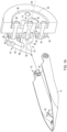
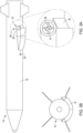
FIGs. 1A and1B are drawings of an embodiment of a hinge with on-axis rotational stop and shearing mechanisms for controllable detachment of a cover from an aerodynamic body; -
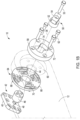
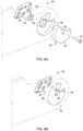
FIGs. 2A through 2C illustrate an embodiment for assembly of the hinge to mount the cover on the aerodynamic body; -
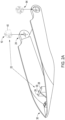
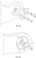
FIGs. 3A-3B ,4A-4B and5A-5B are perspective and on-axis illustrations of a cover at 0° of rotation, 45° of rotation to the hard stop and detached from the aerodynamic body; -
FIGs. 6A and 6B is an illustration of another embodiment of the hinge in which the hinge plates and a portion of the on-axis member are integrally formed with the aerodynamic body and cover; -
FIG. 7 is an illustration of an integrally formed on-axis member for an embodiment of a hinge; and -
FIGs. 8A and 8B are perspective and end-on views of an on-axis member in which the stopping feature is formed within the full diameter region that engages the thru hole in the cover for rotation about the axis of rotation. - The present invention provides a hinge in which internal on-axis stopping mechanisms cause the hinge to shear and break at an on-axis weakened region of the hinge when rotation of the hinge reaches a predetermined angle with a specified torsional load. The on-axis configuration is compact, has minimal impact on the OML of the object to which it is mounted both pre and post detachment and allows for accurate tailoring of the load that will detach the hinge.
- Although generally desirably in most applications, these features are of particular importance to aerodynamic bodies such as missiles that travel at very high speeds. Space on or in an aerodynamic body of this type is at a premium. The on-axis configuration of the hinge is very compact, its footprint being only that of the hinge components that support rotation of the cover. Because the aerodynamic body travels at high speeds its OML is carefully designed for aerodynamics, to limit local thermal effects and disruption of the boundary layer of airflow over the body. Because all aspects of the hinge are internal, the hinge itself creates minimal impact on the OML either pre or post-detachment of the cover. Furthermore, the on-axis hinge design limits FOD in the primary flow path of an air-breating system if used to cover an air intake, for example.
- A hinge comprises first and second hinge plates configured for attachment to first and second solid objects, respectively. An on-axis member extends from the first hinge plate along an axis of rotation into a thru hole in the second hinge plate. A force exerted on the second solid object rotates the second solid object around the axis of rotation. The on-axis member includes a stopping feature and a weakened region positioned between the first hinge plate and the stopping feature. The second hinge plate includes a complementary stopping feature configured in the thru hole to engage the on-axis member's stopping feature at a predetermined angle of rotation to produce a torsional load on the on-axis member that creates torsional shear of the on-axis member at the weakened region to detach the hinge and remove the second solid object from the first solid object. The weakened region may, for example, constitute a smaller diameter region of the member, a slit or aperture formed in the member or varying material properties.
- In different embodiments, the second solid object may be a cover that is permanently detached to uncover a previously covered area. In certain embodiments, the covered area may include a protected element within the first solid object. For example, aerodynamic bodies such as missiles, rockets, guided artillery shells, UAVs, drones, manned aircraft or spacecraft may include protected elements such as optical sensing systems, air inlets or the like that must be protected in flight until those elements are operational.
- In an airborne platform, a cover is reversibly secured to an aerodynamic body to protect a protected element from an external environment. A releasing mechanism (e.g., a pyro technic or piston actuator for controlled release or springloaded or airflow for release at launch) is provided for at least partially detaching the cover from the aerodynamic body. A securing assembly secures the cover to the aerodynamic body. The securing assembly includes the hinge for connecting a first end of the cover to a first region of the aerodynamic body with a releasable element (e.g., tension screws, bands or other mechanically connected element) securing a second end of the cover to a second region of the aerodynamic body. The hinge is configured such that when the second end of the cover separates from the second region of the aerodynamic body in flight, a force (e.g., airflow or as provided by the releasing mechanism) exerted on the cover rotates the cover about an axis of rotation to engage the hinge's internal complementary stopping features at a predetermined angle thereby producing a torsional load that shears the hinge at the on-axis weakened region to release the cover. The hinge is compact and provides minimal impact on the OML of the aerodynamic body either pre or post-detachment.
- The hinge may be designed in different ways reflecting varying degrees of integration of its component elements and with the solid objects to which it is attached. Different configurations may be selected and possibly combined depending upon the application. Without loss of generality, a
hinge 10 using discrete components to secure and then controllably detach acover 12 from amissile 14 will be presented with reference toFigures 1A-1B ,2A-2C ,3A-3B ,4A-4B and5A-5B . -
Missile 14 includes anaerodynamic body 16, a protectedelement 18 within the aerodynamic body and cover 12, reversibly secured to the aerodynamic body, for protecting the protected element from an external environment. A releasingmechanism 20 such as a pyrotechnic actuator or a piston actuator is configured to at least partially detach the cover from the aerodynamic body. A securingassembly 22 secures the cover to the aerodynamic body. The securingassembly 22 includes thehinge 10 for connecting afirst end 24 of the cover to afirst region 26 of the aerodynamic body, and areleasable element 28 such as tension screws, bands or other mechanically connected element securing asecond end 30 of the cover to asecond region 32 of the aerodynamic body.Hinge 10 is configured such that when thesecond end 30 of the cover separates from thesecond region 32 of the aerodynamic body when the missile is in flight, aforce 34 exerted on the cover rotates the cover about an axis ofrotation 36 before detaching thehinge 10, thereby removing thecover 12 frommissile 14.Force 34 may, for example, be provided by the releasingmechanism 20 or by airflow over the aerodynamic body. - In this discrete configuration, hinge 10 includes a
first hinge plate 40 attached to theaerodynamic body 16. An on-axis member 42 extends from thefirst hinge plate 40 along the axis ofrotation 36 aligned with a first thruhole 44 incover 12. The on-axis member includes afull diameter region 46 equal in diameter to the first thruhole 44 in the cover and a reduced diameter weakenedregion 48 positioned between thefirst hinge plate 40 and thefull diameter region 46. Ahard stop 50 includes afull diameter region 52 fastened to the end of thefull diameter region 46 of the on-axis member via afastener 53 and a stoppingfeature 54.Full diameter region 52 is in rotational engagement with the first thruhole 44 in the cover such that theforce 34 rotates the cover around the axis of rotation. - A load transfer interface, shown here as a plurality of shear pins 56, couples the
full diameter region 52 of thehard stop 50 to thefull diameter region 46 of the on-axis member 42. The interface serves to transfer a torsional load created when the complementary stopping features are engaged to the weakened region of the on-axis member. The cumulative shear strength of the interface, here the plurality of shear pins, must be greater than the shear strength of the weakened region. For example, the weakened region may exhibit a shear of 80 lbf (pound feet) while the pins cumulative strength is 100 Ibf. Under more strenuous flight conditions, the weakened region may exhibit a torsional shear of 425 lbf while the pins cumulative strength is 500 Ibf. This can be achieved by varying the diameter of the weakened region or by maintaining the same geometry but varying the material properties of the on-axis member versus the hard stop. Note, thefastener 53 that fastens the hard stop to the on-axis member has minimal affect on load transfer, its purpose is to secure the hard stop to the on-axis member. - A
second hinge plate 58 is positioned in arecess 60 incover 12 and attached (clamped) to the cover viafasteners 62 that engage aring assembly 64 positioned on the inner surface of the cover opposite the second hinge plate.Ring assembly 64 includes a floatingnut plate 66 that is attached to aring 68 viafasteners 70.Second hinge plate 58 has a second thru hole 72 aligned to the first thruhole 44. The second hinge plate has a complementary stoppingfeature 74 configured in the second thru hole 72 to engage the hard stop's stoppingfeature 54 at a predetermined angle of rotation to producemoment 76 about the axis ofrotation 36 to transfer atorsional load 78 thru theload transfer interface 56 to shear the on-axis member 42 at the reduced diameter weakenedregion 48 to detach thehinge 10 and remove thecover 12 from theaerodynamic body 16 leaving thefirst hinge plate 40 and a small proturbance 80 (what remains of the weakened region 48) attached to the aerodynamic body. - Referring specifically to
FIGs. 2A-2C , hinge 10 is assembled to attachcover 12 toaerodynamic body 16 by attaching thefirst hinge plates 40 to the aerodynamic body.Ring assembly 64 is placed on the on-axis member 42 that extends from the first hinge plates along the axis of rotation.Cover 12 is positioned to align thruhole 44 with the on-axis member 42 and axis ofrotation 36 as shown inFIG. 2A . Thesecond hinge plate 58 is placed inrecess 60 andfasteners 70 are inserted through the second hinge plate to engagering assembly 64 to clamp thesecond hinge plate 58 to cover 12 as shown inFIG. 2B . Lastly,hard stop 50 is coupled to on-axis member 42 via shear pins 56 andfastener 53 between itsfull diameter region 52 and the on-axis memberfull diameter region 46 as shown inFIG. 2C . - Referring specifically to
FIGs. 3A-3B ,4A-4B and5A-5B , hinge 10 is engaged in flight to controllably release and permanently detachcover 12. As shown inFIGs. 3A-3B , hinge 10 and cover 12 are secured in a closed or stowed position at 0° of rotation. Thesecond end 30 of the cover is secured to thesecond region 32 of theaerodynamic body 16 to protect the protected element 18 (e.g. an air intake). At 0° of rotation, the cover's complementary stoppingfeature 74 does not engage thehard stop 50. As shown inFIGs. 4A-4B , the releasing mechanism (pyrotechnic actuator) 20 has separated the releasable elements 28 (tension screws) to partially detachcover 12 fromaerodynamic body 16. The airflow over the aerodynamic body producesforces 34 that are exerted oncover 12 causingcover 12 to rotate about axis ofrotation 36 to 45° of rotation at which point the cover's complementary stoppingfeature 74 has engaged thehard stop 50 producing amoment 76 about the axis of rotation, which in turn producestorsional load 78. Shear pins 56 transfer thetorsional load 78 to the reduced diameter weakenedregion 48 of the on off-axis member. As shown inFIGs. 5A-5B , hinge 10 has sheared off at the reduced diameter weakenedregion 48 leaving only asmall proturbance 80 on thefirst hinge plate 40 attached toaerodynamic body 16. - Referring now to
FIGs. 6A-6B , in an embodiment of a hinge 100 afirst hinge plate 102 and a portion of an on-axis member 104 including a reduced diameter weakenedregion 106 and afull diameter region 108 are integrally formed with the aerodynamic body and asecond hinge plate 112 including a complementary stoppingfeature 114 is integrally formed in a thruhole 116 in acover 117. As before,cover 117 is positioned to align thruhole 116 with on-axis member 104 whosefull diameter region 108 nearly contacts the inner surface of the cover. Ahard stop 118 is attached is attached to on-axis member 104 viafastener 119. In this example, the load transfer interface is implemented with asplined interface 115 formed on the opposing surfaces of the on-axis member 104 and thehard stop 118. - Referring now to
FIG. 7 , in an embodiment of ahinge 120, an on-axis member 122 is integrally formed to include a reduced diameter weakenedregion 124, afull diameter region 126 and a stoppingfeature 128. In one configuration, a thruhole 130 in acover 132 is aligned to a mountingfeature 134 on the aerodynamic body. The on-axis member 122 is inserted in the through hole to engage mountingfeature 134. A complementary stoppingfeature 136 may be formed either in a hinge plate attached to cover 132 or integrally in thruhole 130 in the cover as shown in the drawing. An integrally formed on-axis member does not require a load transfer interface to transfer the torsional load produced by engagement of the complementary stopping features to the reduced diameter weakened region. - The on-axis hinge includes both a full diameter region in rotational engagement with a thru hole in the cover/hinge plate to provide reliable and stable rotation of the cover about the axis of rotation away from the aerodynamic body and complementary stopping features formed on the on-axis member and in the thru hole that engage at a predetermined angle and shear the hinge to permanently detach the cover. Up to this point, the complementary stopping features are physically offset axially from the full diameter region of the on-axis member and the thru hole and functionally separately. However, the complementary stopping features may be incorporated into the full diameter region of the on-axis member and the thru hole. In so doing, a portion of the 360° degrees of possible rotational engagement between the full diameter region of the on-axis member and the inner surface of the thru hole must be sacrificed. How much of the360° degrees must be sacrificed depends both on the predetermined angle of rotation at which the complementary stopping features are engaged and the geometry of those features. This may be implemented in either a discrete configuration in which a hard stop is pinned to the on-axis member or in which the hard stop is integrally formed with the on-axis member.
- Referring now to
FIGs. 8A-8B , in an embodiment of ahinge 140, an on-axis member 142 includes a reduced diameter weakenedregion 144 and afull diameter region 146. Ahard stop 148 is coupled to the on-axis member via shear pins 150 andfastener 152.Hard stop 148 includes afull diameter region 154 in which a quadrant has been removed to form a stoppingfeature 156. A complementary stoppingfeature 158 is formed in a wall of a full diameter thru hole 160 to engage stoppingfeature 156 at a predetermined angle. - While several illustrative embodiments of the invention have been shown and described, numerous variations and alternate embodiments will occur to those skilled in the art. Such variations and alternate embodiments are contemplated, and can be made while still falling within the scope of the invention as defined in the appended claims.
Claims (15)
- A hinge (10), comprising:a first hinge plate (40) configured for attachment to a first solid object (16);an on-axis member (42) that extends from the first hinge plate along an axis of rotation (36), said on-axis member including a stopping feature (54) and a weakened region (48) positioned between the first hinge plate and the stopping feature; anda second hinge plate (58) configured for attachment to a second solid object (12), said second hinge plate having a thru hole (72) for receiving the on-axis member such that a force exerted on the second solid object rotates the second solid object around the axis of rotation, said second hinge plate having a complementary stopping feature (74) configured in said thru hole to engage the on-axis member's stopping feature at a predetermined angle of rotation to produce a torsional load on the on-axis member that shears the on-axis member at the weakened region to detach the hinge and remove the second solid object from the first solid object.
- The hinge of claim 1, wherein said stopping feature is a discrete component (50) fastened to an end of the on-axis member, said hinge further comprising a load transfer interface (56, 115) that couples the stopping feature to the on-axis member to transfer the torsional load to shear the on-axis member at the weakened region.
- The hinge of claim 2, wherein the load transfer interface comprises one of a plurality of shear pins (56) or a splined interface (115).
- The hinge of claim 2, wherein said discrete component includes a full diameter region (52) equal to the diameter of the thru hole in rotational engagement with the thru hole in the second hinge plate at the load transfer interface; and
preferably, wherein said on-axis member includes an integrally formed full diameter region (46), adjacent the weakened region, that is coupled to the full diameter region of the discrete component via the load transfer interface. - The hinge of claim 1, wherein at least one of the first hinge plate or the second hinge plate is integrally formed with the first solid object or the second solid object, respectively.
- The hinge of claim 1, wherein the first hinge plate and at least the weakened region of the on-axis member are integrally formed with the first solid obj ect.
- The hinge of claim 1, wherein said on-axis member is integrally formed to include the weakened region and the stopping feature.
- The hinge of claim 1, wherein said on-axis member includes a full diameter region (46) equal to the diameter of the thru hole in rotational engagement with the thru hole in the second hinge plate.
- The hinge of claim 8, wherein the stopping feature is offset axial from the full diameter region to engage the complementary stopping feature; or
wherein the stopping feature is formed in the full diameter region to engage the complementary stopping feature. - A platform (14) comprising:a body (16);a solid object (12), reversibly secured to said body;a releasing mechanism (20) for at least partially detaching said solid object from said body; anda securing assembly (22) for securing said solid object to said body, said securing assembly including a hinge (10) for connecting a first end (24) of said solid object to a first region (26) of said body, and a releasable element (28) securing a second end (30) of said solid object to a second region (32) of said body;said hinge being configured such that when said second end of said solid obj ect separates from said second region of said body, a force exerted on said solid obj ect rotates the solid object about an axis of rotation before detaching said hinge, thereby removing said solid object from said body; andwherein said hinge includesan on-axis member (42) that extends from the body thru a thru hole (44) in the solid object along the axis of rotation such that the force rotates the solid object around the axis of rotation, said on-axis member including a stopping feature (54) positioned within the thru hole in the solid object and a weakened region (48) positioned between the body and the stopping feature; anda complementary stopping feature (74) configured in the thru hole in the solid object to engage the on-axis member's stopping feature at a predetermined angle of rotation to produce a torsional load on the on-axis member that shears the on-axis member at the weakened region to detach the hinge and remove the solid object from the body.
- The platform of claim 10, wherein said stopping feature is a discrete component (50) fastened to an end of the on-axis member, said hinge further comprising a load transfer interface (56, 115) that couples the stopping feature to the on-axis member to transfer the torsional load to shear the on-axis member at the weakened region.
- The platform of claim 11, wherein said stopping feature includes a full diameter region (52) equal to the diameter of the thru hole in rotational engagement with the thru hole in the second hinge plate at the load transfer interface, wherein said on-axis member includes an integrally formed full diameter region (46), adjacent the weakened region, that is coupled to the full diameter region of the stopping feature via the load transfer interface; or
wherein said on-axis member is integrally formed to include the weakened region and the stopping feature. - The platform of claim 11, wherein said on-axis member includes a full diameter region equal to the diameter of the thru hole in rotational engagement with the thru hole in the second hinge plate, wherein the stopping feature is offset axial from the full diameter region to engage the complementary stopping feature; or
wherein said on-axis member includes a full diameter region equal to the diameter of the thru hole in rotational engagement with the thru hole in the second hinge plate, wherein the stopping feature is formed in the full diameter region to engage the complementary stopping feature. - An airborne platform (14) comprising:an aerodynamic body (16);a protected element (18) within said aerodynamic body;a cover (12), reversibly secured to said aerodynamic body, for protecting said protected element from an external environment;a releasing mechanism (20) for at least partially detaching said cover from said aerodynamic body; anda securing assembly (22) for securing said cover to said aerodynamic body, said securing assembly including a hinge (10) for connecting a first end (24) of said cover to a first region (26) of said aerodynamic body, and a releasable element (28) securing a second end (30) of said cover to a second region (32) of said aerodynamic body;said hinge being configured such that when said second end of said cover separates from said second region of said aerodynamic body when the airborne platform is in flight, a force exerted on said cover rotates the cover about an axis of rotation before detaching said hinge, thereby removing said cover from said aerodynamic body, andwherein said hinge includesa recess (60) in the cover with a first thru hole (44);a first hinge plate (40) attached to the aerodynamic body;an on-axis member (42) that extends from the first hinge plate along the axis of rotation aligned with the first thru hole, said on-axis member including a full diameter region (46) equal in diameter to the first thru hole in the cover and a reduced diameter weakened region (48) positioned between the first hinge plate and the full diameter region;a hard stop (50) including a full diameter region (52) fastened to the end of the full diameter region of the on-axis member and a stopping feature (54), said full diameter region in rotational engagement with the first thru hole in the cover such that the force rotates the cover around the axis of rotation;a load transfer interface (56, 115) that couples the full diameter region of the hard stop to the full diameter region of the on-axis member; anda second hinge plate (58) positioned in the recess and attached to the cover, said second hinge plate having a second thru hole (72) aligned to the first thru hole, said second hinge plate having with a complementary stopping feature (74) configured in the second thru hole to engage the hard stop's stopping feature at a predetermined angle of rotation to transfer a torsional load thru the load transfer interface to shear the on-axis member at the reduced diameter weakened region to detach the hinge and remove the cover from the aerodynamic body leaving the first hinge plate attached to the aerodynamic body.
- The platform of claim 14, wherein the load transfer interface comprises one of a plurality of shear pins (56) or a splined interface (115); or
wherein detachment of the hinge leaves a small proturbance (80) from the weakened region of the hinge attached to the first hinge plate.
Applications Claiming Priority (2)
| Application Number | Priority Date | Filing Date | Title |
|---|---|---|---|
| US17/348,371 US12038040B2 (en) | 2021-06-15 | 2021-06-15 | Hinge with internal on-axis rotational stop and shearing mechanisms |
| PCT/US2022/029632 WO2022265787A1 (en) | 2021-06-15 | 2022-05-17 | Hinge with internal on-axis rotational stop and shearing mechanisms |
Publications (2)
| Publication Number | Publication Date |
|---|---|
| EP4356015A1 EP4356015A1 (en) | 2024-04-24 |
| EP4356015B1 true EP4356015B1 (en) | 2024-09-04 |
Family
ID=82016327
Family Applications (1)
| Application Number | Title | Priority Date | Filing Date |
|---|---|---|---|
| EP22729374.3A Active EP4356015B1 (en) | 2021-06-15 | 2022-05-17 | Hinge with internal on-axis rotational stop and shearing mechanisms |
Country Status (4)
| Country | Link |
|---|---|
| US (1) | US12038040B2 (en) |
| EP (1) | EP4356015B1 (en) |
| ES (1) | ES2994035T3 (en) |
| WO (1) | WO2022265787A1 (en) |
Families Citing this family (2)
| Publication number | Priority date | Publication date | Assignee | Title |
|---|---|---|---|---|
| US12038040B2 (en) | 2021-06-15 | 2024-07-16 | Raytheon Company | Hinge with internal on-axis rotational stop and shearing mechanisms |
| CN116424578A (en) * | 2023-04-06 | 2023-07-14 | 北京微纳星空科技有限公司 | A solar wing synchronous deployment structure |
Family Cites Families (23)
| Publication number | Priority date | Publication date | Assignee | Title |
|---|---|---|---|---|
| GB576683A (en) * | 1932-07-29 | 1934-01-04 | George Purves Douglas | Improvements in bombs or the like intended to be dropped from aircraft |
| DE1147807B (en) * | 1953-11-02 | 1963-04-25 | Wilhelm Bahmueller | Tooth alignment lock |
| CH358289A (en) * | 1958-05-07 | 1961-11-15 | Bahmueller Wilhelm | Locking device on two parts that are hinged to one another |
| US3188685A (en) | 1961-10-27 | 1965-06-15 | Ternes Steel Company | Windshield visor hinge |
| US3397903A (en) * | 1966-06-13 | 1968-08-20 | John H. Archdale | Artificial limb joint |
| US3706281A (en) | 1971-04-01 | 1972-12-19 | Nasa | Method and system for ejecting fairing sections from a rocket vehicle |
| CH662503A5 (en) * | 1984-01-20 | 1987-10-15 | Ernst Kaeser Fabrik Von Elektr | Manual massaging device |
| DE3511991A1 (en) * | 1984-07-04 | 1986-01-16 | Metallwerk Frese Gmbh, 5653 Leichlingen | Device for setting torque |
| US4874145A (en) | 1986-10-27 | 1989-10-17 | Rockwell International Corporation | Missile air inlet cover retractor system |
| US5265969A (en) * | 1992-12-16 | 1993-11-30 | Chuang Ching Pao | Angle-adjustable joint |
| US6244779B1 (en) * | 1998-06-03 | 2001-06-12 | Michael Slasinski | Angularly adjustable coupling |
| IL139891A (en) | 2000-11-23 | 2004-07-25 | Rafael Armament Dev Authority | Jettisonable protective element |
| DE10240040A1 (en) | 2002-08-27 | 2004-03-11 | BODENSEEWERK GERäTETECHNIK GMBH | Guided missile with detachable protective cap |
| US7037287B2 (en) | 2003-09-29 | 2006-05-02 | Royce Medical Company | Adjustable ergonomic knee brace |
| TWM274205U (en) * | 2005-01-19 | 2005-09-01 | Nano Prec Corp | Torque adjusting module |
| IL189089A0 (en) | 2008-01-28 | 2008-08-07 | Rafael Advanced Defense Sys | Apparatus and method for splitting and removing a shroud from an airborne vehicle |
| US8519312B1 (en) | 2010-01-29 | 2013-08-27 | Raytheon Company | Missile with shroud that separates in flight |
| US8461501B2 (en) | 2010-11-02 | 2013-06-11 | Raytheon Company | Guided munitions including self-deploying dome covers and methods for equipping guided munitions with the same |
| DE102010054567B4 (en) * | 2010-12-15 | 2015-08-20 | Rheinmetall Landsysteme Gmbh | Plastically deformable storage |
| CN205578494U (en) * | 2015-12-28 | 2016-09-14 | 深圳市鑫宝临五金有限公司 | Angle adjustment device |
| US20200003253A1 (en) * | 2018-06-28 | 2020-01-02 | Koncept Technologies Inc. | Friction hinges and devices |
| CN208933479U (en) | 2018-09-27 | 2019-06-04 | 中海福陆重工有限公司 | A kind of jacket anode erector |
| US12038040B2 (en) | 2021-06-15 | 2024-07-16 | Raytheon Company | Hinge with internal on-axis rotational stop and shearing mechanisms |
-
2021
- 2021-06-15 US US17/348,371 patent/US12038040B2/en active Active
-
2022
- 2022-05-17 ES ES22729374T patent/ES2994035T3/en active Active
- 2022-05-17 EP EP22729374.3A patent/EP4356015B1/en active Active
- 2022-05-17 WO PCT/US2022/029632 patent/WO2022265787A1/en not_active Ceased
Also Published As
| Publication number | Publication date |
|---|---|
| US12038040B2 (en) | 2024-07-16 |
| US20220397150A1 (en) | 2022-12-15 |
| WO2022265787A1 (en) | 2022-12-22 |
| EP4356015A1 (en) | 2024-04-24 |
| ES2994035T3 (en) | 2025-01-16 |
Similar Documents
| Publication | Publication Date | Title |
|---|---|---|
| US7673833B2 (en) | Protective shield assembly for space optics and associated methods | |
| US12038040B2 (en) | Hinge with internal on-axis rotational stop and shearing mechanisms | |
| EP2279116B1 (en) | Aircraft flight termination system and method | |
| IL118251A (en) | Missile control system and method for its use | |
| KR20100138883A (en) | Appliances for removing and removing covers from aircraft | |
| US6679453B2 (en) | Jettisonable protective element | |
| JP2017519177A (en) | Missile with separable protective fairing | |
| IL186284A (en) | Ejectable aerodynamic stability and control | |
| US6227096B1 (en) | Universal warhead adapter, and missile and method incorporating same | |
| US7040210B2 (en) | Apparatus and method for restraining and releasing a control surface | |
| US10094646B2 (en) | Spring-assisted deployment of a pivotable rocket motor | |
| KR100385812B1 (en) | Open Petal Type Rocket Stage Separation System | |
| CN113650809B (en) | Space carrier cabin section blanking cover, cabin section structure and space carrier | |
| US10030952B1 (en) | Thermally deployable shroud for affordable precision guided projectile | |
| US8461501B2 (en) | Guided munitions including self-deploying dome covers and methods for equipping guided munitions with the same | |
| KR100362998B1 (en) | Clamp Block Type Rocket Nose Fairing System | |
| US11940260B2 (en) | Device for detecting the absence of a mechanical barrier for a missile and missile comprising such a device | |
| CN119289795A (en) | A launch vehicle fairing and design method |
Legal Events
| Date | Code | Title | Description |
|---|---|---|---|
| STAA | Information on the status of an ep patent application or granted ep patent |
Free format text: STATUS: UNKNOWN |
|
| STAA | Information on the status of an ep patent application or granted ep patent |
Free format text: STATUS: THE INTERNATIONAL PUBLICATION HAS BEEN MADE |
|
| PUAI | Public reference made under article 153(3) epc to a published international application that has entered the european phase |
Free format text: ORIGINAL CODE: 0009012 |
|
| STAA | Information on the status of an ep patent application or granted ep patent |
Free format text: STATUS: REQUEST FOR EXAMINATION WAS MADE |
|
| 17P | Request for examination filed |
Effective date: 20231222 |
|
| AK | Designated contracting states |
Kind code of ref document: A1 Designated state(s): AL AT BE BG CH CY CZ DE DK EE ES FI FR GB GR HR HU IE IS IT LI LT LU LV MC MK MT NL NO PL PT RO RS SE SI SK SM TR |
|
| GRAP | Despatch of communication of intention to grant a patent |
Free format text: ORIGINAL CODE: EPIDOSNIGR1 |
|
| STAA | Information on the status of an ep patent application or granted ep patent |
Free format text: STATUS: GRANT OF PATENT IS INTENDED |
|
| DAV | Request for validation of the european patent (deleted) | ||
| DAX | Request for extension of the european patent (deleted) | ||
| INTG | Intention to grant announced |
Effective date: 20240527 |
|
| GRAS | Grant fee paid |
Free format text: ORIGINAL CODE: EPIDOSNIGR3 |
|
| GRAA | (expected) grant |
Free format text: ORIGINAL CODE: 0009210 |
|
| STAA | Information on the status of an ep patent application or granted ep patent |
Free format text: STATUS: THE PATENT HAS BEEN GRANTED |
|
| AK | Designated contracting states |
Kind code of ref document: B1 Designated state(s): AL AT BE BG CH CY CZ DE DK EE ES FI FR GB GR HR HU IE IS IT LI LT LU LV MC MK MT NL NO PL PT RO RS SE SI SK SM TR |
|
| REG | Reference to a national code |
Ref country code: GB Ref legal event code: FG4D |
|
| REG | Reference to a national code |
Ref country code: CH Ref legal event code: EP |
|
| REG | Reference to a national code |
Ref country code: IE Ref legal event code: FG4D |
|
| REG | Reference to a national code |
Ref country code: DE Ref legal event code: R096 Ref document number: 602022005905 Country of ref document: DE |
|
| REG | Reference to a national code |
Ref country code: SE Ref legal event code: TRGR |
|
| REG | Reference to a national code |
Ref country code: LT Ref legal event code: MG9D |
|
| REG | Reference to a national code |
Ref country code: NL Ref legal event code: MP Effective date: 20240904 |
|
| PG25 | Lapsed in a contracting state [announced via postgrant information from national office to epo] |
Ref country code: GR Free format text: LAPSE BECAUSE OF FAILURE TO SUBMIT A TRANSLATION OF THE DESCRIPTION OR TO PAY THE FEE WITHIN THE PRESCRIBED TIME-LIMIT Effective date: 20241205 Ref country code: FI Free format text: LAPSE BECAUSE OF FAILURE TO SUBMIT A TRANSLATION OF THE DESCRIPTION OR TO PAY THE FEE WITHIN THE PRESCRIBED TIME-LIMIT Effective date: 20240904 |
|
| REG | Reference to a national code |
Ref country code: ES Ref legal event code: FG2A Ref document number: 2994035 Country of ref document: ES Kind code of ref document: T3 Effective date: 20250116 |
|
| PG25 | Lapsed in a contracting state [announced via postgrant information from national office to epo] |
Ref country code: BG Free format text: LAPSE BECAUSE OF FAILURE TO SUBMIT A TRANSLATION OF THE DESCRIPTION OR TO PAY THE FEE WITHIN THE PRESCRIBED TIME-LIMIT Effective date: 20240904 |
|
| PG25 | Lapsed in a contracting state [announced via postgrant information from national office to epo] |
Ref country code: LV Free format text: LAPSE BECAUSE OF FAILURE TO SUBMIT A TRANSLATION OF THE DESCRIPTION OR TO PAY THE FEE WITHIN THE PRESCRIBED TIME-LIMIT Effective date: 20240904 |
|
| PG25 | Lapsed in a contracting state [announced via postgrant information from national office to epo] |
Ref country code: HR Free format text: LAPSE BECAUSE OF FAILURE TO SUBMIT A TRANSLATION OF THE DESCRIPTION OR TO PAY THE FEE WITHIN THE PRESCRIBED TIME-LIMIT Effective date: 20240904 |
|
| PG25 | Lapsed in a contracting state [announced via postgrant information from national office to epo] |
Ref country code: RS Free format text: LAPSE BECAUSE OF FAILURE TO SUBMIT A TRANSLATION OF THE DESCRIPTION OR TO PAY THE FEE WITHIN THE PRESCRIBED TIME-LIMIT Effective date: 20241204 |
|
| PG25 | Lapsed in a contracting state [announced via postgrant information from national office to epo] |
Ref country code: RS Free format text: LAPSE BECAUSE OF FAILURE TO SUBMIT A TRANSLATION OF THE DESCRIPTION OR TO PAY THE FEE WITHIN THE PRESCRIBED TIME-LIMIT Effective date: 20241204 Ref country code: LV Free format text: LAPSE BECAUSE OF FAILURE TO SUBMIT A TRANSLATION OF THE DESCRIPTION OR TO PAY THE FEE WITHIN THE PRESCRIBED TIME-LIMIT Effective date: 20240904 Ref country code: HR Free format text: LAPSE BECAUSE OF FAILURE TO SUBMIT A TRANSLATION OF THE DESCRIPTION OR TO PAY THE FEE WITHIN THE PRESCRIBED TIME-LIMIT Effective date: 20240904 Ref country code: GR Free format text: LAPSE BECAUSE OF FAILURE TO SUBMIT A TRANSLATION OF THE DESCRIPTION OR TO PAY THE FEE WITHIN THE PRESCRIBED TIME-LIMIT Effective date: 20241205 Ref country code: FI Free format text: LAPSE BECAUSE OF FAILURE TO SUBMIT A TRANSLATION OF THE DESCRIPTION OR TO PAY THE FEE WITHIN THE PRESCRIBED TIME-LIMIT Effective date: 20240904 Ref country code: BG Free format text: LAPSE BECAUSE OF FAILURE TO SUBMIT A TRANSLATION OF THE DESCRIPTION OR TO PAY THE FEE WITHIN THE PRESCRIBED TIME-LIMIT Effective date: 20240904 |
|
| REG | Reference to a national code |
Ref country code: AT Ref legal event code: MK05 Ref document number: 1720683 Country of ref document: AT Kind code of ref document: T Effective date: 20240904 |
|
| PG25 | Lapsed in a contracting state [announced via postgrant information from national office to epo] |
Ref country code: NL Free format text: LAPSE BECAUSE OF FAILURE TO SUBMIT A TRANSLATION OF THE DESCRIPTION OR TO PAY THE FEE WITHIN THE PRESCRIBED TIME-LIMIT Effective date: 20240904 |
|
| PG25 | Lapsed in a contracting state [announced via postgrant information from national office to epo] |
Ref country code: PT Free format text: LAPSE BECAUSE OF FAILURE TO SUBMIT A TRANSLATION OF THE DESCRIPTION OR TO PAY THE FEE WITHIN THE PRESCRIBED TIME-LIMIT Effective date: 20250106 Ref country code: IS Free format text: LAPSE BECAUSE OF FAILURE TO SUBMIT A TRANSLATION OF THE DESCRIPTION OR TO PAY THE FEE WITHIN THE PRESCRIBED TIME-LIMIT Effective date: 20250104 |
|
| PG25 | Lapsed in a contracting state [announced via postgrant information from national office to epo] |
Ref country code: RO Free format text: LAPSE BECAUSE OF FAILURE TO SUBMIT A TRANSLATION OF THE DESCRIPTION OR TO PAY THE FEE WITHIN THE PRESCRIBED TIME-LIMIT Effective date: 20240904 Ref country code: SM Free format text: LAPSE BECAUSE OF FAILURE TO SUBMIT A TRANSLATION OF THE DESCRIPTION OR TO PAY THE FEE WITHIN THE PRESCRIBED TIME-LIMIT Effective date: 20240904 |
|
| PG25 | Lapsed in a contracting state [announced via postgrant information from national office to epo] |
Ref country code: EE Free format text: LAPSE BECAUSE OF FAILURE TO SUBMIT A TRANSLATION OF THE DESCRIPTION OR TO PAY THE FEE WITHIN THE PRESCRIBED TIME-LIMIT Effective date: 20240904 Ref country code: AT Free format text: LAPSE BECAUSE OF FAILURE TO SUBMIT A TRANSLATION OF THE DESCRIPTION OR TO PAY THE FEE WITHIN THE PRESCRIBED TIME-LIMIT Effective date: 20240904 |
|
| PG25 | Lapsed in a contracting state [announced via postgrant information from national office to epo] |
Ref country code: PL Free format text: LAPSE BECAUSE OF FAILURE TO SUBMIT A TRANSLATION OF THE DESCRIPTION OR TO PAY THE FEE WITHIN THE PRESCRIBED TIME-LIMIT Effective date: 20240904 Ref country code: CZ Free format text: LAPSE BECAUSE OF FAILURE TO SUBMIT A TRANSLATION OF THE DESCRIPTION OR TO PAY THE FEE WITHIN THE PRESCRIBED TIME-LIMIT Effective date: 20240904 |
|
| PG25 | Lapsed in a contracting state [announced via postgrant information from national office to epo] |
Ref country code: SK Free format text: LAPSE BECAUSE OF FAILURE TO SUBMIT A TRANSLATION OF THE DESCRIPTION OR TO PAY THE FEE WITHIN THE PRESCRIBED TIME-LIMIT Effective date: 20240904 |
|
| REG | Reference to a national code |
Ref country code: DE Ref legal event code: R097 Ref document number: 602022005905 Country of ref document: DE |
|
| PGFP | Annual fee paid to national office [announced via postgrant information from national office to epo] |
Ref country code: DE Payment date: 20250423 Year of fee payment: 4 |
|
| PG25 | Lapsed in a contracting state [announced via postgrant information from national office to epo] |
Ref country code: DK Free format text: LAPSE BECAUSE OF FAILURE TO SUBMIT A TRANSLATION OF THE DESCRIPTION OR TO PAY THE FEE WITHIN THE PRESCRIBED TIME-LIMIT Effective date: 20240904 |
|
| PGFP | Annual fee paid to national office [announced via postgrant information from national office to epo] |
Ref country code: ES Payment date: 20250602 Year of fee payment: 4 |
|
| PLBE | No opposition filed within time limit |
Free format text: ORIGINAL CODE: 0009261 |
|
| STAA | Information on the status of an ep patent application or granted ep patent |
Free format text: STATUS: NO OPPOSITION FILED WITHIN TIME LIMIT |
|
| PGFP | Annual fee paid to national office [announced via postgrant information from national office to epo] |
Ref country code: NO Payment date: 20250424 Year of fee payment: 4 |
|
| PGFP | Annual fee paid to national office [announced via postgrant information from national office to epo] |
Ref country code: IT Payment date: 20250531 Year of fee payment: 4 |
|
| PGFP | Annual fee paid to national office [announced via postgrant information from national office to epo] |
Ref country code: FR Payment date: 20250423 Year of fee payment: 4 |
|
| PGFP | Annual fee paid to national office [announced via postgrant information from national office to epo] |
Ref country code: SE Payment date: 20250423 Year of fee payment: 4 |
|
| 26N | No opposition filed |
Effective date: 20250605 |
|
| REG | Reference to a national code |
Ref country code: CH Ref legal event code: H13 Free format text: ST27 STATUS EVENT CODE: U-0-0-H10-H13 (AS PROVIDED BY THE NATIONAL OFFICE) Effective date: 20251223 |
|
| PG25 | Lapsed in a contracting state [announced via postgrant information from national office to epo] |
Ref country code: LU Free format text: LAPSE BECAUSE OF NON-PAYMENT OF DUE FEES Effective date: 20250517 |
|
| PG25 | Lapsed in a contracting state [announced via postgrant information from national office to epo] |
Ref country code: CH Free format text: LAPSE BECAUSE OF NON-PAYMENT OF DUE FEES Effective date: 20250531 |
|
| REG | Reference to a national code |
Ref country code: BE Ref legal event code: MM Effective date: 20250531 |
|
| PG25 | Lapsed in a contracting state [announced via postgrant information from national office to epo] |
Ref country code: MC Free format text: LAPSE BECAUSE OF FAILURE TO SUBMIT A TRANSLATION OF THE DESCRIPTION OR TO PAY THE FEE WITHIN THE PRESCRIBED TIME-LIMIT Effective date: 20240904 |
|
| PG25 | Lapsed in a contracting state [announced via postgrant information from national office to epo] |
Ref country code: IE Free format text: LAPSE BECAUSE OF NON-PAYMENT OF DUE FEES Effective date: 20250517 |
|
| PG25 | Lapsed in a contracting state [announced via postgrant information from national office to epo] |
Ref country code: BE Free format text: LAPSE BECAUSE OF NON-PAYMENT OF DUE FEES Effective date: 20250531 |