EP4355216B1 - Method for determining longitudinal position of combined phantom, computer readable storage medium, and ct device - Google Patents
Method for determining longitudinal position of combined phantom, computer readable storage medium, and ct device Download PDFInfo
- Publication number
- EP4355216B1 EP4355216B1 EP21769641.8A EP21769641A EP4355216B1 EP 4355216 B1 EP4355216 B1 EP 4355216B1 EP 21769641 A EP21769641 A EP 21769641A EP 4355216 B1 EP4355216 B1 EP 4355216B1
- Authority
- EP
- European Patent Office
- Prior art keywords
- phantom
- combined
- length
- current
- channel
- Prior art date
- Legal status (The legal status is an assumption and is not a legal conclusion. Google has not performed a legal analysis and makes no representation as to the accuracy of the status listed.)
- Active
Links
Images

Classifications
-
- A—HUMAN NECESSITIES
- A61—MEDICAL OR VETERINARY SCIENCE; HYGIENE
- A61B—DIAGNOSIS; SURGERY; IDENTIFICATION
- A61B6/00—Apparatus or devices for radiation diagnosis; Apparatus or devices for radiation diagnosis combined with radiation therapy equipment
- A61B6/58—Testing, adjusting or calibrating thereof
- A61B6/582—Calibration
- A61B6/583—Calibration using calibration phantoms
-
- A—HUMAN NECESSITIES
- A61—MEDICAL OR VETERINARY SCIENCE; HYGIENE
- A61B—DIAGNOSIS; SURGERY; IDENTIFICATION
- A61B6/00—Apparatus or devices for radiation diagnosis; Apparatus or devices for radiation diagnosis combined with radiation therapy equipment
- A61B6/02—Arrangements for diagnosis sequentially in different planes; Stereoscopic radiation diagnosis
- A61B6/03—Computed tomography [CT]
- A61B6/032—Transmission computed tomography [CT]
Definitions
- the present invention relates to a method for determining a longitudinal position of a combined phantom.
- the phantom is automatically aligned in a Y direction, but needs to be manually aligned in a Z direction.
- WO 2018/081420 A1 relates to phantoms for the calibration and quality assurance of radiation therapy systems, including biologically-guided radiation therapy systems, which deliver doses of radiation in response to real-time detected PET lines-of-response (LORs).
- the phantoms disclosed herein are modular phantoms that comprise a cylindrical housing with a plurality of disks stacked within the housing and a plurality of radiographic films. Some disks have a background region and a target region, where the rate of positron emissions of the target region is higher than for the background region. The disks may be arranged and rearranged within the housing to attain a desired target region shape.
- US 2012/076259 A1 relates to the improving of the accuracy of a computed tomography (CT) process.
- This can comprise operably coupling at least one calibration phantom to a CT scan table and then, during a CT scan of an object that is disposed on the scan table, also gathering calibration information using that calibration phantom(s).
- this calibration phantom can comprise one or more annular-shaped members.
- this calibration phantom can comprise one or more pins and/or spherically-shaped members (and/or other shapes of geometric interest). If desired, such spherically-shaped members can be combined with the aforementioned pins.
- the present invention provides a method for determining a longitudinal position of a combined phantom, a computer readable storage medium, and a CT device.
- a method of determining a longitudinal position of a combined phantom includes: scanning the combined phantom to obtain a topogram thereof, the combined phantom being fixed to a table top and protruding beyond the table top, the combined phantom being axially parallel to the longitudinal direction, the combined phantom including a plurality of phantoms and one of which being a slice phantom; identifying the plurality of phantoms on the topogram; and using an axial center of the slice phantom as the longitudinal position of the combined phantom.
- the identifying the plurality of phantoms on the topogram includes: for each reading i, calculating a channel quantity Ci greater than an air HU value, 0 ⁇ i ⁇ N-1 and N being a total quantity of readings; smoothing a curve of the channel quantity Ci; using a phantom length between a start position of a non-air part greater than a minimum phantom radial size and a radial size change portion as a measured length of a current phantom; and if the measured length of the current phantom is close to a length of the current phantom, identifying the current phantom.
- the smoothing a curve of the channel quantity C i includes: determining that adjacent readings with close channel quantities belong to the same phantom; and averaging the channel quantities of the same phantom.
- the channel quantities being close refers to:
- T C 4.
- the measured length of the current phantom being close to the length of the current phantom refers to:
- L j is a measured length of a phantom j
- L j,default is a length of the phantom j
- T L is a positive threshold
- T L 2 mm.
- Step S114 Identify the current phantom if the measured length of the current phantom is close to a length of the current phantom.
Landscapes
- Health & Medical Sciences (AREA)
- Life Sciences & Earth Sciences (AREA)
- Engineering & Computer Science (AREA)
- Medical Informatics (AREA)
- Radiology & Medical Imaging (AREA)
- Molecular Biology (AREA)
- Biophysics (AREA)
- Nuclear Medicine, Radiotherapy & Molecular Imaging (AREA)
- Optics & Photonics (AREA)
- Pathology (AREA)
- Physics & Mathematics (AREA)
- Biomedical Technology (AREA)
- Heart & Thoracic Surgery (AREA)
- High Energy & Nuclear Physics (AREA)
- Surgery (AREA)
- Animal Behavior & Ethology (AREA)
- General Health & Medical Sciences (AREA)
- Public Health (AREA)
- Veterinary Medicine (AREA)
- Pulmonology (AREA)
- Theoretical Computer Science (AREA)
- Apparatus For Radiation Diagnosis (AREA)
Description
- The present invention relates to a method for determining a longitudinal position of a combined phantom.
- When a CT manufacturer releases a new software version, all on-site systems will be upgraded to this version. If some changes need tuning, all the affected systems need on-site services, which causes a heavy workload to service engineers. One solution for this is to instruct a customer to place a phantom on a correct holder and automatically align the phantom.
- In addition, on a production line, the phantom is automatically aligned in a Y direction, but needs to be manually aligned in a Z direction.
-
US 2005/141672 A1 relates to a phantom assembly that comprises a plurality of the phantoms and an x-ray radiation from an x-ray CT device inserted in through-holes. -
WO 2018/081420 A1 relates to phantoms for the calibration and quality assurance of radiation therapy systems, including biologically-guided radiation therapy systems, which deliver doses of radiation in response to real-time detected PET lines-of-response (LORs). The phantoms disclosed herein are modular phantoms that comprise a cylindrical housing with a plurality of disks stacked within the housing and a plurality of radiographic films. Some disks have a background region and a target region, where the rate of positron emissions of the target region is higher than for the background region. The disks may be arranged and rearranged within the housing to attain a desired target region shape. -
US 2012/076259 A1 relates to the improving of the accuracy of a computed tomography (CT) process. This can comprise operably coupling at least one calibration phantom to a CT scan table and then, during a CT scan of an object that is disposed on the scan table, also gathering calibration information using that calibration phantom(s). By one approach, this calibration phantom can comprise one or more annular-shaped members. When using a plurality of annular-shaped members, at least some of the annular-shaped members can be disposed concentrically with one another. By one approach, in lieu of the foregoing or in combination therewith, this calibration phantom can comprise one or more pins and/or spherically-shaped members (and/or other shapes of geometric interest). If desired, such spherically-shaped members can be combined with the aforementioned pins. - In view of this, the present invention provides a method for determining a longitudinal position of a combined phantom, a computer readable storage medium, and a CT device.
- According to a first aspect of the present invention, a method of determining a longitudinal position of a combined phantom is provided and includes: scanning the combined phantom to obtain a topogram thereof, the combined phantom being fixed to a table top and protruding beyond the table top, the combined phantom being axially parallel to the longitudinal direction, the combined phantom including a plurality of phantoms and one of which being a slice phantom; identifying the plurality of phantoms on the topogram; and using an axial center of the slice phantom as the longitudinal position of the combined phantom.
- In an embodiment, the identifying the plurality of phantoms on the topogram includes: for each reading i, calculating a channel quantity Ci greater than an air HU value, 0≤ i≤ N-1 and N being a total quantity of readings; smoothing a curve of the channel quantity Ci; using a phantom length between a start position of a non-air part greater than a minimum phantom radial size and a radial size change portion as a measured length of a current phantom; and if the measured length of the current phantom is close to a length of the current phantom, identifying the current phantom.
- In an embodiment, the smoothing a curve of the channel quantity Ci includes: determining that adjacent readings with close channel quantities belong to the same phantom; and averaging the channel quantities of the same phantom.
- In an embodiment, the channel quantities being close refers to: |Ci - C i+1| < TC
where TC is a positive integer threshold. - In an embodiment, TC = 4.
- In an embodiment, the measured length of the current phantom being close to the length of the current phantom refers to: |Lj - Lj,default | < TL
where Lj is a measured length of a phantom j, Lj,default is a length of the phantom j, and TL is a positive threshold. - In an embodiment, TL = 2mm.
- In an embodiment, the longitudinal direction is a direction in which the table top enters and exits a computed tomography device.
- According to a second aspect of the present invention, a computer readable storage medium is provided, on which a computer program is stored, and the program is executed by a processor to implement the method as described above.
- According to a third aspect of the present invention, a computed tomography device is provided and includes a memory, a processor, and a computer program stored in the memory and executed by the processor, the processor implementing the method as described above when executing the program.
- According to the method for determining a longitudinal position of a combined phantom, the computer readable storage medium, and the CT device in the present invention, the longitudinal position is determined by using the topogram of the combined phantom, and a phantom position can be quickly and automatically aligned.
- To enable a person of ordinary skill in the art to understand the foregoing and other features and advantages of the present invention more clearly, exemplary embodiments according to the present invention are described in detail below with reference to the accompany drawings. In the accompany drawings:
-
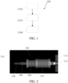
FIG. 1 is a schematic flowchart of a method for determining a longitudinal position of a combined phantom according to an embodiment of the present invention. -
FIG. 2 is a schematic diagram of a topogram according to an embodiment of the present invention. -
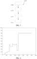
FIG. 3 is a schematic flowchart of identifying a plurality of phantoms on a topogram according to an embodiment of the present invention. -
FIG. 4 is a curve of a reading with regard to a channel quantity greater than an air HU value according to an embodiment of the present invention. -
FIG. 5 is a schematic flowchart of smoothing a curve of a channel quantity according to an embodiment of the present invention. - In the accompany drawings, reference numerals used are as follows:
100 Method 108 Slice phantom S102, S104, S106, S108, S110, S112, S114, S116, and S118 Steps 110 Water phantom 102 Combined phantom 112 Holder 104 Focus alignment phantom 114 Table top 106 High-resolution phantom - To make the objective, technical solutions, and advantages of the present invention clearer, the present invention is further described in detail below by using embodiments.
-
FIG. 1 is a schematic flowchart of amethod 100 for determining a longitudinal position of a combined phantom according to an embodiment of the present invention, andFIG. 2 is a schematic diagram of atopogram 116 according to an embodiment of the present invention. As shown inFIG. 1 and FIG. 2 , themethod 100 for determining a longitudinal position of a combined phantom includes step S102, step S104, and step S106. - Step S102: Scan a combined
phantom 102 to obtain atopogram 116 thereof. The combinedphantom 102 is fixed to atable top 114, for example, by using aholder 112 and protrudes beyond thetable top 114. Therefore, it can be seen from thetopogram 116 that air is around the combinedphantom 102. It should be noted that in the present invention, the so-called longitudinal direction is a direction in which the table top enters and exits a computed tomography device, that is, a direction Z. The combinedphantom 102 is axially parallel to the longitudinal direction, and includes a plurality of phantoms, one of which is aslice phantom 108. In this embodiment, the combinedphantom 102 includes afocus alignment phantom 104, a high-resolution phantom 106, theslice phantom 108, and awater phantom 110. - Step S104: Identify the foregoing phantoms on the
topogram 116.FIG. 3 is a schematic flowchart of identifying a plurality of phantoms on a topogram according to an embodiment of the present invention. As shown inFIG. 3 , in this embodiment, step S104 may include step S108, step S110, step S112, and step S114. - Step S108: Calculate, for each reading i, a channel quantity Ci greater than an air HU value, 0 ≤ i ≤ N - 1 and N being a total quantity of readings.
FIG. 4 is a curve of a reading with regard to a channel quantity Ci greater than an air HU value according to an embodiment of the present invention. - Step S110: Smooth a curve of the channel quantity Ci .
- Step S112: Use a phantom length between a start position of a non-air part greater than a minimum phantom radial size and a radial size change portion as a measured length of a current phantom.
- Step S114: Identify the current phantom if the measured length of the current phantom is close to a length of the current phantom.
-
FIG. 5 is a schematic flowchart of smoothing a curve of a channel quantity Ci according to an embodiment of the present invention. As shown inFIG. 5 , step S110 of smoothing the curve of the channel quantity Ci includes step S116 and step S118. - Step S116: Determine that adjacent readings with close channel quantities belong to the same phantom. The channel quantities being close may be represented as:

- Step S118: Average the channel quantities of the same phantom.
- In step S114, the measured length of the current phantom being close to the length of the current phantom refers to:

- As shown in
FIG. 1 , after step S104 of identifying the phantom on thetopogram 116, in step S106, an axial center of theslice phantom 108 is used as the longitudinal position of the combinedphantom 102. - After the longitudinal position of the combined phantom is calculated, a position of another phantom may be checked according to the position and a default distance of each phantom in a configuration table. If all phantoms can cover a longitudinal range of scanning, the longitudinal position of the phantom is confirmed.
- According to another aspect of the present invention, a computer readable storage medium is provided, storing a computer program, and the program, when executed by a processor, implementing the
method 100 for determining a longitudinal position of a combined phantom. - According to still another aspect of the present invention, a computed tomography device is provided, including a memory, a processor, and a computer program stored on the memory and executable on the processor, the processor implementing the
method 100 for determining a longitudinal position of a combined phantom when executing the program. - According to the method for determining a longitudinal position of a combined phantom, the computer readable storage medium, and the CT device in the present invention, the longitudinal position is determined by using the topogram of the combined phantom, which can quickly and automatically align a phantom position.
- The foregoing descriptions are merely preferred embodiments of the present invention, but are not intended to limit the present invention.
Claims (10)
- A method for determining a longitudinal position of a combined phantom (102) in a computed tomography device, comprising:scanning the combined phantom (102) to obtain a topogram (116) thereof, the combined phantom (102) being fixed to a table top (114) and protruding beyond the table top (114), the combined phantom (102) being axially parallel to the longitudinal direction, the combined phantom (102) comprising a plurality of phantoms and one of which being a slice phantom (108);identifying the plurality of phantoms on the topogram (116); andusing an axial center of the slice phantom (108) as the longitudinal position of the combined phantom (102).
- The method according to claim 1, wherein the identifying the plurality of phantoms on the topogram (116) comprises:for each reading i, calculating a channel quantity Ci greater than an air HU value, 0 ≤ i ≤ N-1 and N being a total quantity of readings;smoothing a curve of the channel quantity Ci;using a phantom length between a start position of a non-air part greater than a minimum phantom radial size and a radial size change portion as a measured length of a current phantom; andif the measured length of the current phantom is close to a length of the current phantom, identifying the current phantom.
- The method according to claim 2, wherein the smoothing a curve of the channel quantity Ci comprises:determining that adjacent readings with close channel quantities belong to the same phantom; andaveraging the channel quantities of the same phantom.
- The method according to claim 3, wherein the channel quantities being close refers to:

- The method according to claim 4, wherein Tc=4.
- The method according to claim 2, wherein the measured length of the current phantom being close to the length of the current phantom refers to:

- The method according to claim 6, wherein TL=2mm.
- The method according to claim 1, wherein the longitudinal direction is a direction in which the table top enters and exits the computed tomography device.
- A computer readable storage medium that stores a computer program, the program being executed by a processor to implement the method according to any one of claims 1 to 8.
- A computed tomography device, comprising a memory, a processor, and a computer program stored in the memory and executed by the processor, the processor implementing the method according to any one of claims 1 to 8 when executing the program.
Applications Claiming Priority (2)
| Application Number | Priority Date | Filing Date | Title |
|---|---|---|---|
| CN202110817910.9A CN115633972A (en) | 2021-07-20 | 2021-07-20 | Method for determining longitudinal position of combined phantom, computer readable storage medium and CT device |
| PCT/CN2021/115082 WO2023000437A1 (en) | 2021-07-20 | 2021-08-27 | Method for determining longitudinal position of combined phantom, computer readable storage medium, and ct device |
Publications (4)
| Publication Number | Publication Date |
|---|---|
| EP4355216A1 EP4355216A1 (en) | 2024-04-24 |
| EP4355216B1 true EP4355216B1 (en) | 2025-02-26 |
| EP4355216C0 EP4355216C0 (en) | 2025-02-26 |
| EP4355216B8 EP4355216B8 (en) | 2025-04-02 |
Family
ID=77738900
Family Applications (1)
| Application Number | Title | Priority Date | Filing Date |
|---|---|---|---|
| EP21769641.8A Active EP4355216B8 (en) | 2021-07-20 | 2021-08-27 | Method for determining longitudinal position of combined phantom, computer readable storage medium, and ct device |
Country Status (4)
| Country | Link |
|---|---|
| US (1) | US12521073B2 (en) |
| EP (1) | EP4355216B8 (en) |
| CN (1) | CN115633972A (en) |
| WO (1) | WO2023000437A1 (en) |
Families Citing this family (1)
| Publication number | Priority date | Publication date | Assignee | Title |
|---|---|---|---|---|
| WO2025243061A1 (en) | 2024-05-24 | 2025-11-27 | Totalenergies Onetech | A method for building a reservoir model according to a sequence of geological events |
Family Cites Families (11)
| Publication number | Priority date | Publication date | Assignee | Title |
|---|---|---|---|---|
| US4296329A (en) * | 1979-10-22 | 1981-10-20 | General Electric Company | Alignment device for computerized tomography phantoms |
| US6148057A (en) * | 1998-11-02 | 2000-11-14 | Analogic Corporation | Apparatus and method for calibrating detectors in a computed tomography scanner |
| DE10324683A1 (en) * | 2003-05-30 | 2005-01-05 | Siemens Ag | Method for carrying out test measurements in an X-ray computed tomography scanner and X-ray computed tomography scanner |
| JP4284411B2 (en) | 2003-12-24 | 2009-06-24 | 独立行政法人放射線医学総合研究所 | Phantom and phantom aggregate |
| US8777485B2 (en) | 2010-09-24 | 2014-07-15 | Varian Medical Systems, Inc. | Method and apparatus pertaining to computed tomography scanning using a calibration phantom |
| WO2018081420A1 (en) * | 2016-10-28 | 2018-05-03 | Reflexion Medical, Inc. | Methods for radiation therapy quality assurance and verification |
| CN107582088A (en) * | 2017-09-28 | 2018-01-16 | 江苏省计量科学研究院 | A Composite Phantom for PET/CT Image Performance Evaluation |
| CN110041559A (en) | 2018-01-17 | 2019-07-23 | 昆山瑞正金属制品有限公司 | A kind of resin efficient recycling method |
| CN112535488A (en) * | 2019-09-23 | 2021-03-23 | 佳能医疗系统株式会社 | Analysis device |
| CN111419257B (en) * | 2020-04-07 | 2022-11-22 | 南京安科医疗科技有限公司 | Automatic positioning method of calibration phantom, scanning system and readable storage medium |
| CN112674786A (en) * | 2020-12-29 | 2021-04-20 | 安徽省第二人民医院(安徽医学高等专科学校附属医院、安徽省职业病防治院) | Novel CT (computed tomography) phantom for evaluating clinical image quality of TCM (TCM) and IR (Infrared radiation) algorithms |
-
2021
- 2021-07-20 CN CN202110817910.9A patent/CN115633972A/en active Pending
- 2021-08-27 WO PCT/CN2021/115082 patent/WO2023000437A1/en not_active Ceased
- 2021-08-27 EP EP21769641.8A patent/EP4355216B8/en active Active
- 2021-08-27 US US18/579,951 patent/US12521073B2/en active Active
Also Published As
| Publication number | Publication date |
|---|---|
| CN115633972A (en) | 2023-01-24 |
| WO2023000437A1 (en) | 2023-01-26 |
| US12521073B2 (en) | 2026-01-13 |
| US20240335173A1 (en) | 2024-10-10 |
| EP4355216B8 (en) | 2025-04-02 |
| EP4355216C0 (en) | 2025-02-26 |
| EP4355216A1 (en) | 2024-04-24 |
Similar Documents
| Publication | Publication Date | Title |
|---|---|---|
| US11116471B2 (en) | Methods and apparatus for extended low contrast detectability for radiographic imaging systems | |
| US7983457B2 (en) | Method and system for automatically determining regions in a scanned object | |
| US8891849B2 (en) | Extended low contrast detectability for radiographic imaging systems | |
| US6409383B1 (en) | Automated and quantitative method for quality assurance of digital radiography imaging systems | |
| Clarke et al. | Application of draft European Commission reference levels to a regional CT dose survey. | |
| US10667767B2 (en) | Systems and methods for selecting bowtie filter configuration | |
| Takenaga et al. | Modulation transfer function measurement of CT images by use of a circular edge method with a logistic curve-fitting technique | |
| US6528803B1 (en) | Automated calibration adjustment for film dosimetry | |
| EP3029634B1 (en) | Echogenicity quantification method and calibration method for ultrasonic device using echogenicity index | |
| US20150086094A1 (en) | Echogenicity quantification method and calibration method for ultrasonic device using echogenicity index | |
| JP3908993B2 (en) | X-ray CT system | |
| EP4340727B1 (en) | Ct beam hardening correction method, ct beam hardening correction device, and storage medium | |
| Elnour et al. | Assessment of image quality parameters for computed tomography in Sudan | |
| WO2015020981A2 (en) | Systems and methods for determining radiation dose in computed tomography scans | |
| US12521073B2 (en) | Determination of longitudinal position of combined phantom | |
| US20060219964A1 (en) | Recording sheet usage count evaluation method and apparatus, and medical image processing apparatus | |
| US7111985B2 (en) | Method and system for measuring table sag | |
| US20140029822A1 (en) | Patient-size-adjusted dose estimation | |
| Cournane et al. | Establishing how patient size and degree of miscentring affect CTDIvol, using patient data from a dose tracking system | |
| JP3048164B2 (en) | X-ray CT system | |
| CN114504335A (en) | CT machine bulb tube positioning correction method, storage medium and terminal equipment | |
| Sathiakumar et al. | NEMA NU 2-2001 performance testing of a Philips Gemini GXL PET/CT scanner | |
| CN210697663U (en) | Body model for CT annular artifact correction | |
| Takemitsu et al. | The effect of a pre-reconstruction process in a filtered back projection reconstruction on an image quality of a low tube voltage computed tomography | |
| US20240120072A1 (en) | System and method for obtaining quality image data and measurements from a medical imaging device |
Legal Events
| Date | Code | Title | Description |
|---|---|---|---|
| STAA | Information on the status of an ep patent application or granted ep patent |
Free format text: STATUS: UNKNOWN |
|
| STAA | Information on the status of an ep patent application or granted ep patent |
Free format text: STATUS: THE INTERNATIONAL PUBLICATION HAS BEEN MADE |
|
| PUAI | Public reference made under article 153(3) epc to a published international application that has entered the european phase |
Free format text: ORIGINAL CODE: 0009012 |
|
| STAA | Information on the status of an ep patent application or granted ep patent |
Free format text: STATUS: REQUEST FOR EXAMINATION WAS MADE |
|
| 17P | Request for examination filed |
Effective date: 20240117 |
|
| AK | Designated contracting states |
Kind code of ref document: A1 Designated state(s): AL AT BE BG CH CY CZ DE DK EE ES FI FR GB GR HR HU IE IS IT LI LT LU LV MC MK MT NL NO PL PT RO RS SE SI SK SM TR |
|
| RIN1 | Information on inventor provided before grant (corrected) |
Inventor name: LOU, YU TING Inventor name: TIAN, YI Inventor name: GU, XUAN Inventor name: LI, TAO TAO |
|
| GRAP | Despatch of communication of intention to grant a patent |
Free format text: ORIGINAL CODE: EPIDOSNIGR1 |
|
| STAA | Information on the status of an ep patent application or granted ep patent |
Free format text: STATUS: GRANT OF PATENT IS INTENDED |
|
| DAV | Request for validation of the european patent (deleted) | ||
| DAX | Request for extension of the european patent (deleted) | ||
| RIC1 | Information provided on ipc code assigned before grant |
Ipc: A61B 6/58 20240101ALI20241010BHEP Ipc: A61B 6/03 20060101ALI20241010BHEP Ipc: A61B 6/00 20240101AFI20241010BHEP |
|
| INTG | Intention to grant announced |
Effective date: 20241024 |
|
| GRAS | Grant fee paid |
Free format text: ORIGINAL CODE: EPIDOSNIGR3 |
|
| GRAA | (expected) grant |
Free format text: ORIGINAL CODE: 0009210 |
|
| STAA | Information on the status of an ep patent application or granted ep patent |
Free format text: STATUS: THE PATENT HAS BEEN GRANTED |
|
| AK | Designated contracting states |
Kind code of ref document: B1 Designated state(s): AL AT BE BG CH CY CZ DE DK EE ES FI FR GB GR HR HU IE IS IT LI LT LU LV MC MK MT NL NO PL PT RO RS SE SI SK SM TR |
|
| REG | Reference to a national code |
Ref country code: GB Ref legal event code: FG4D |
|
| REG | Reference to a national code |
Ref country code: CH Ref legal event code: EP |
|
| REG | Reference to a national code |
Ref country code: CH Ref legal event code: PK Free format text: BERICHTIGUNG B8 |
|
| RAP4 | Party data changed (patent owner data changed or rights of a patent transferred) |
Owner name: SIEMENS SHANGHAI MEDICAL EQUIPMENT LTD. |
|
| REG | Reference to a national code |
Ref country code: DE Ref legal event code: R096 Ref document number: 602021026829 Country of ref document: DE |
|
| REG | Reference to a national code |
Ref country code: IE Ref legal event code: FG4D |
|
| U01 | Request for unitary effect filed |
Effective date: 20250226 |
|
| U07 | Unitary effect registered |
Designated state(s): AT BE BG DE DK EE FI FR IT LT LU LV MT NL PT RO SE SI Effective date: 20250306 |
|
| PG25 | Lapsed in a contracting state [announced via postgrant information from national office to epo] |
Ref country code: RS Free format text: LAPSE BECAUSE OF FAILURE TO SUBMIT A TRANSLATION OF THE DESCRIPTION OR TO PAY THE FEE WITHIN THE PRESCRIBED TIME-LIMIT Effective date: 20250526 |
|
| PG25 | Lapsed in a contracting state [announced via postgrant information from national office to epo] |
Ref country code: PL Free format text: LAPSE BECAUSE OF FAILURE TO SUBMIT A TRANSLATION OF THE DESCRIPTION OR TO PAY THE FEE WITHIN THE PRESCRIBED TIME-LIMIT Effective date: 20250226 |
|
| PG25 | Lapsed in a contracting state [announced via postgrant information from national office to epo] |
Ref country code: ES Free format text: LAPSE BECAUSE OF FAILURE TO SUBMIT A TRANSLATION OF THE DESCRIPTION OR TO PAY THE FEE WITHIN THE PRESCRIBED TIME-LIMIT Effective date: 20250226 |
|
| PG25 | Lapsed in a contracting state [announced via postgrant information from national office to epo] |
Ref country code: IS Free format text: LAPSE BECAUSE OF FAILURE TO SUBMIT A TRANSLATION OF THE DESCRIPTION OR TO PAY THE FEE WITHIN THE PRESCRIBED TIME-LIMIT Effective date: 20250626 Ref country code: NO Free format text: LAPSE BECAUSE OF FAILURE TO SUBMIT A TRANSLATION OF THE DESCRIPTION OR TO PAY THE FEE WITHIN THE PRESCRIBED TIME-LIMIT Effective date: 20250526 |
|
| PG25 | Lapsed in a contracting state [announced via postgrant information from national office to epo] |
Ref country code: HR Free format text: LAPSE BECAUSE OF FAILURE TO SUBMIT A TRANSLATION OF THE DESCRIPTION OR TO PAY THE FEE WITHIN THE PRESCRIBED TIME-LIMIT Effective date: 20250226 |
|
| PG25 | Lapsed in a contracting state [announced via postgrant information from national office to epo] |
Ref country code: GR Free format text: LAPSE BECAUSE OF FAILURE TO SUBMIT A TRANSLATION OF THE DESCRIPTION OR TO PAY THE FEE WITHIN THE PRESCRIBED TIME-LIMIT Effective date: 20250527 |
|
| U20 | Renewal fee for the european patent with unitary effect paid |
Year of fee payment: 5 Effective date: 20250820 |
|
| PG25 | Lapsed in a contracting state [announced via postgrant information from national office to epo] |
Ref country code: SM Free format text: LAPSE BECAUSE OF FAILURE TO SUBMIT A TRANSLATION OF THE DESCRIPTION OR TO PAY THE FEE WITHIN THE PRESCRIBED TIME-LIMIT Effective date: 20250226 |
|
| PG25 | Lapsed in a contracting state [announced via postgrant information from national office to epo] |
Ref country code: CZ Free format text: LAPSE BECAUSE OF FAILURE TO SUBMIT A TRANSLATION OF THE DESCRIPTION OR TO PAY THE FEE WITHIN THE PRESCRIBED TIME-LIMIT Effective date: 20250226 |
|
| PG25 | Lapsed in a contracting state [announced via postgrant information from national office to epo] |
Ref country code: SK Free format text: LAPSE BECAUSE OF FAILURE TO SUBMIT A TRANSLATION OF THE DESCRIPTION OR TO PAY THE FEE WITHIN THE PRESCRIBED TIME-LIMIT Effective date: 20250226 |
|
| PLBE | No opposition filed within time limit |
Free format text: ORIGINAL CODE: 0009261 |
|
| STAA | Information on the status of an ep patent application or granted ep patent |
Free format text: STATUS: NO OPPOSITION FILED WITHIN TIME LIMIT |
|
| REG | Reference to a national code |
Ref country code: CH Ref legal event code: L10 Free format text: ST27 STATUS EVENT CODE: U-0-0-L10-L00 (AS PROVIDED BY THE NATIONAL OFFICE) Effective date: 20260107 |
|
| 26N | No opposition filed |
Effective date: 20251127 |
|
| REG | Reference to a national code |
Ref country code: CH Ref legal event code: H13 Free format text: ST27 STATUS EVENT CODE: U-0-0-H10-H13 (AS PROVIDED BY THE NATIONAL OFFICE) Effective date: 20260324 |
|
| PG25 | Lapsed in a contracting state [announced via postgrant information from national office to epo] |
Ref country code: MC Free format text: LAPSE BECAUSE OF FAILURE TO SUBMIT A TRANSLATION OF THE DESCRIPTION OR TO PAY THE FEE WITHIN THE PRESCRIBED TIME-LIMIT Effective date: 20250226 |
|
| PG25 | Lapsed in a contracting state [announced via postgrant information from national office to epo] |
Ref country code: CH Free format text: LAPSE BECAUSE OF NON-PAYMENT OF DUE FEES Effective date: 20250831 |
|
| GBPC | Gb: european patent ceased through non-payment of renewal fee |
Effective date: 20250827 |