EP4354996A1 - Bwp switching method, network device, and storage medium - Google Patents
Bwp switching method, network device, and storage medium Download PDFInfo
- Publication number
- EP4354996A1 EP4354996A1 EP22832046.1A EP22832046A EP4354996A1 EP 4354996 A1 EP4354996 A1 EP 4354996A1 EP 22832046 A EP22832046 A EP 22832046A EP 4354996 A1 EP4354996 A1 EP 4354996A1
- Authority
- EP
- European Patent Office
- Prior art keywords
- bwp
- terminal
- switching
- network device
- moment
- Prior art date
- Legal status (The legal status is an assumption and is not a legal conclusion. Google has not performed a legal analysis and makes no representation as to the accuracy of the status listed.)
- Pending
Links
Images


Classifications
-
- H—ELECTRICITY
- H04—ELECTRIC COMMUNICATION TECHNIQUE
- H04W—WIRELESS COMMUNICATION NETWORKS
- H04W36/00—Hand-off or reselection arrangements
- H04W36/06—Reselecting a communication resource in the serving access point
-
- H—ELECTRICITY
- H04—ELECTRIC COMMUNICATION TECHNIQUE
- H04W—WIRELESS COMMUNICATION NETWORKS
- H04W72/00—Local resource management
- H04W72/04—Wireless resource allocation
- H04W72/044—Wireless resource allocation based on the type of the allocated resource
- H04W72/0453—Resources in frequency domain, e.g. a carrier in FDMA
-
- H—ELECTRICITY
- H04—ELECTRIC COMMUNICATION TECHNIQUE
- H04L—TRANSMISSION OF DIGITAL INFORMATION, e.g. TELEGRAPHIC COMMUNICATION
- H04L5/00—Arrangements affording multiple use of the transmission path
- H04L5/0001—Arrangements for dividing the transmission path
- H04L5/0003—Two-dimensional division
- H04L5/0005—Time-frequency
- H04L5/0007—Time-frequency the frequencies being orthogonal, e.g. OFDM(A) or DMT
- H04L5/001—Time-frequency the frequencies being orthogonal, e.g. OFDM(A) or DMT the frequencies being arranged in component carriers
-
- H—ELECTRICITY
- H04—ELECTRIC COMMUNICATION TECHNIQUE
- H04L—TRANSMISSION OF DIGITAL INFORMATION, e.g. TELEGRAPHIC COMMUNICATION
- H04L5/00—Arrangements affording multiple use of the transmission path
- H04L5/0091—Signalling for the administration of the divided path, e.g. signalling of configuration information
- H04L5/0096—Indication of changes in allocation
- H04L5/0098—Signalling of the activation or deactivation of component carriers, subcarriers or frequency bands
-
- H—ELECTRICITY
- H04—ELECTRIC COMMUNICATION TECHNIQUE
- H04W—WIRELESS COMMUNICATION NETWORKS
- H04W28/00—Network traffic management; Network resource management
- H04W28/16—Central resource management; Negotiation of resources or communication parameters, e.g. negotiating bandwidth or QoS [Quality of Service]
-
- H—ELECTRICITY
- H04—ELECTRIC COMMUNICATION TECHNIQUE
- H04W—WIRELESS COMMUNICATION NETWORKS
- H04W36/00—Hand-off or reselection arrangements
- H04W36/0005—Control or signalling for completing the hand-off
- H04W36/0055—Transmission or use of information for re-establishing the radio link
- H04W36/0079—Transmission or use of information for re-establishing the radio link in case of hand-off failure or rejection
-
- H—ELECTRICITY
- H04—ELECTRIC COMMUNICATION TECHNIQUE
- H04W—WIRELESS COMMUNICATION NETWORKS
- H04W56/00—Synchronisation arrangements
- H04W56/001—Synchronization between nodes
-
- H—ELECTRICITY
- H04—ELECTRIC COMMUNICATION TECHNIQUE
- H04W—WIRELESS COMMUNICATION NETWORKS
- H04W72/00—Local resource management
- H04W72/20—Control channels or signalling for resource management
- H04W72/23—Control channels or signalling for resource management in the downlink direction of a wireless link, i.e. towards a terminal
- H04W72/232—Control channels or signalling for resource management in the downlink direction of a wireless link, i.e. towards a terminal the control data signalling from the physical layer, e.g. DCI signalling
Definitions
- Embodiments of the present application relate to the technical field of 5G communications, in particular to a BWP switching method, a network device, and a storage medium.
- a system bandwidth namely a bandwidth of a carrier wave
- a network device will configure a bandwidth part (BWP) for the terminals, for example, 20 MHz, and the terminals may communicate with the network device over the configured BWP.
- the network device may configure a plurality of BWPs for the terminals, some of which have narrower bandwidths and others have wider bandwidths.
- one terminal can have only one active BWP, the terminal can receive or send data only over the active BWP.
- the network device may instruct the terminal to switch to a BWP with a broad bandwidth; and if the terminal needs to transmit a small amount of data, the network device may instruct the terminal again to switch to a BWP with a narrow bandwidth.
- the terminal may perform BWP switching through instruction of downlink control information (DCI), however, there is misdetection or false detection when detecting DCI by the terminal, which will enter a BWP switching process unilaterally, while the network device side does not configure a corresponding BWP for the terminal, resulting in interruption of a service of the terminal.
- DCI downlink control information
- an embodiment of the present application provides a BWP switching method, applied to a network device and including: in a case that a working bandwidth of a network device is within a current BWP and a terminal that has performed switching from the current BWP is detected, determining that a BWP switching error is occurred with the terminal that has performed switching from the current BWP; and instructing the terminal with which the BWP switching error is occurred to switch to a target BWP and controlling the network device to switch to the target BWP.
- an embodiment of the present application further provides a network device, including: at least one processor; and a memory in communication connection with the at least one processor; wherein the memory stores instructions executable by the at least one processor, and the instructions are executed by the at least one processor so as to cause the at least one processor to implement the above BWP switching method.
- an embodiment of the present application further provides a computer storage medium having stored thereon a computer program, which, when executed by a processor, implementing the above BWP switching method.
- Main objective of embodiments of the present application is providing a BWP switching method, a network device, and a storage medium, by which a BWP of a terminal may be adjusted for a BWP switching error of the terminal, so the BWP of the terminal keeps consistent with a BWP of a network device side, and thus stability of a service of the terminal is improved.
- a 5G protocol may support BWP switching of the terminal, there are two common manners for BWP switching of the terminal, namely, one manner of BWP switching through radio resource control (RRC) reconfiguration signaling and the other manner of BWP switching through DCI.
- RRC radio resource control
- BWP switching based on RRC is used for enabling user equipment (UE) to immediately enter a proper BWP once the UE completes initial access and enters an RRC connected state or an RRC reconfiguration or a activation of secondary cell (Scell) so as to perform transceiving of a service instead of remaining on an initial BWP.
- UE user equipment
- Scell secondary cell
- a base station may activate a BWP other than the initial BWP through firstActiveDownlinkBWP-Id and firstActiveUplinkBWP-Id, a bandwidth of the BWP is usually larger than that of the initial BWP.
- the terminal may switch from a current BWP, when there is misdetection of DCI or false detection of DCI by the terminal. Due to that the network device does not issue the DCI actually, namely the terminal enters the BWP switching process unilaterally, while the network device remains in the current BWP state, an interruption of the service of the terminal is caused.
- a working bandwidth of the network device is within BWP1
- a working bandwidth of the terminal is also within BWP1
- the current BWP refers to the BWP1
- the terminal enters the BWP switching process unilaterally, while the network device remains in the current BWP state, namely the working bandwidth of the network device remains within the BWP1
- the working bandwidth of the terminal is within BWP2, resulting in interruption of the service of the terminal at this moment.
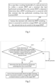
- An embodiment of the present application relates to a BWP switching method, implemented by a network device, the network device is, for example, a base station, and a flow of the method is illustrated in Fig. 1 .
- Step 101 in a case that a working bandwidth of a network device is within a current BWP and a terminal that has performed switching from the current BWP is detected, it is determined that a BWP switching error is occurred with the terminal that has performed switching from the current BWP.
- the terminal may be a mobile device, such as a mobile phone, and the terminal may also be a computer, an Internet of Things device and the like.
- the base station may communicate with a plurality of terminals and may perform the following operations on each terminal in communication: the network device may detect whether the terminal supports a mode of DCI switching BWP, if the terminal does not support the mode of DCI switching BWP, a process of the BWP switching method of the present embodiment ends, and if the terminal supports the mode of DCI switching BWP, whether the terminal has performed switching from the current BWP may be further detected.
- a manner of detecting whether the terminal has performed switching from the current BWP may be determined based on whether a service of the terminal is normal. As the terminal receives data only over an active BWP, if the terminal switches to a false BWP, consequently, the active BWP is inconsistent with the BWP of the network device, resulting in interruption of the service of the terminal, for example, call drop.
- DCI misdetection or DCI false detection by the terminal leads to the BWP switching error occurred with the terminal, and if the terminal does not support the mode of DCI switching BWP, the subsequent process is not needed.
- the method of the present embodiment is implemented by the network device communicating with the terminal, and the terminal in communication supports the mode of DCI switching BWP.
- Step 102 the terminal with which the BWP switching error is occurred is instructed to switch to a target BWP, and the network device is controlled to switch to the target BWP.
- the network device may instruct the terminal to switch to the target BWP in a manner of issuing DCI, where the target BWP may be a preset default BWP, and at the same time, the network device is controlled to switch to the default BWP.
- the default BWP is a preset BWP with a small bandwidth.
- the BWP switching method if the BWP of the terminal is inconsistent with the BWP of the network device, the service between the terminal and the network device may be interrupted, and the use of the terminal is affected; in a case that the working bandwidth of the network device is within the current BWP and it is detected that the terminal has performed switching from the current BWP, it is determined that the BWP switching error is occurred with the terminal, the network device thus instructs the terminal to switch to the target terminal, the network device switches its BWP to the target BWP as well, such that the BWP of the network device is consistent with the BWP of the terminal, avoiding the interruption of the service of the terminal.
- the BWP state of the terminal may be optimized in time, stability of BWP switching is improved, call drop is avoided, and thus the stability of the service of the terminal is improved.
- a specific implementation of detecting whether the terminal has performed switching from the current BWP is provided, and a schematic diagram of this implementation is illustrated in Fig. 2 .
- Step 1011 in a case that the working bandwidth of the network device is within the current BWP, following operations are performed on each terminal communicating with the network device: under detection of the terminal supporting the mode of downlink control information (DCI) based BWP switching, whether the service of the terminal is interrupted within a first preset period of time is detected, if the service of the terminal is interrupted within the first preset period of time, step 1012 is performed, otherwise the process of the BWP switching method in the present application stops.
- DCI downlink control information
- the process of detecting whether the service of the terminal is interrupted within the first preset period of time is: under detection of the terminal being in a discontinuous transmission (DTX) state at a moment T, whether the service of the terminal at a moment T-1 is normal is detected, if normal, then the service of the terminal is interrupted within the first preset period of time is determined, otherwise the service of the terminal is normal within the first preset period of time is determined, wherein T is an integer greater than 1.
- DTX discontinuous transmission
- the first preset period of time includes the moment T and the moment T-1
- the moment T may be a current detection moment
- the moment T-1 may be a previous detection moment.
- the moment T Under detection of the terminal being in the DTX state at the moment T, it indicates that the service of the terminal is interrupted currently; and at this moment, whether the service of the terminal is normal at the previous moment, namely the moment T-1, is detected, if the service of the terminal is normal at the moment T-1, namely the terminal is not in the DTX state, it may be determined that the service of the terminal is normal.
- Step 1012 it is determined that the terminal has performed switching from the current BWP; and step 102 is performed.
- Step 102 the terminal with which the BWP switching error is occurred is instructed to switch to a target BWP, and the network device is controlled to switch to the target BWP.
- the network device determines whether the terminal has performed switching from the current BWP, if the terminal is on a correct active BWP, the service of the terminal may not be interrupted, based on this, in the embodiment, with a detection result of the current detection moment and a detection result of the previous detection moment, whether the terminal has performed switching from the current BWP may be determined accurately, avoiding misjudgment for the terminal that has performed false switching from the current BWP, and improving detection accuracy.
- a specific implementation of instructing the terminal with which the BWP switching error is occurred to switch to the target BWP is provided, and a schematic diagram of the implementation is illustrated in Fig. 3 .
- Step 1011 in a case that the working bandwidth of the network device is within the current BWP, following operations are performed on each terminal communicating with the network device: under detection of the terminal supporting the mode of downlink control information (DCI) based BWP switching, whether the service of the terminal is interrupted within a first preset period of time is detected, if the service of the terminal is interrupted within the first preset period of time, step 1012 is performed, otherwise the process of the BWP switching method in the present application stops.
- DCI downlink control information
- Step 1012 it is determined that the terminal has performed switching from the current BWP. Step 1021 is performed.
- Step 1021 a synchronous moment is provided for the terminal, so that the terminal determines a target switching moment according to the synchronous moment, and the terminal switches to the target BWP at the target switching moment.
- the target BWP may be set as a default BWP, and a BWP fall-back mechanism is started in a manner of providing the synchronous moment for the terminal.
- instruction information may be issued to the terminal, the terminal uses a moment when the instruction information is received as the synchronous moment, and both the terminal and the network device use the synchronous moment as a timekeeping start point and simultaneously trigger the fall-back mechanism when reaching the preset target switching moment to fall back to the default BWP, so that the BWP of the terminal and the BWP of the network device keep consistent.
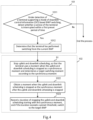
- the manner of the providing the synchronous moment for the terminal may use a manner in step S 1, namely, a manner of a schematic diagram of Fig. 4 of the present embodiment.
- Step S1 uplink and downlink scheduling is stopped, so that the terminal uses a moment when the uplink and downlink scheduling is stopped as the synchronous moment and determines the target switching moment according to the synchronous moment.
- the network device stops the uplink and downlink scheduling.
- the terminal may use a moment when downlink control information for scheduling the terminal is not received as the synchronous moment, and the terminal uses the synchronous moment as the timekeeping start point and switches the BWP when reaching the target switching moment.
- the duration of stopping the uplink and downlink scheduling may be counted from the synchronization moment, for example, a bwp-InactivityTimer is started for counting, and if the duration exceeds a preset threshold, it indicates that the target switching moment is reached.
- Step 1022 the moment when the uplink and downlink scheduling is stopped is obtained as the synchronous moment after the uplink and downlink scheduling is stopped.
- the network device Similar to a process of the terminal obtaining the synchronous moment as described in step 1021, the network device obtains the moment when the uplink and downlink scheduling is stopped as the synchronous moment.
- Step 1023 the duration of stopping the uplink and downlink scheduling is recorded starting with the synchronous moment, and if the duration exceeds the preset threshold, it switches to the target BWP.
- the network device records, starting with the synchronous moment, the duration of stopping the scheduling, and if the duration exceeds the preset threshold, it indicates that the target switching moment is reached. Likewise, counting of the duration may be implemented through the bwp-InactivityTimer. In other words, starting with the synchronous moment, the bwp-InactivityTimer is started, if the duration recorded by the bwp-InactivityTimer exceeds the preset threshold, then the terminal and the network device enter the BWP fall-back mechanism synchronously and both fall back to the corresponding default BWP.
- the terminal and the network device may determine the target switching moment based on the synchronous moment, the terminal and the network device switch to the target BWP synchronously when reaching the target switching moment, and it may be guaranteed that the BWP states of the both are consistent due to synchronous switching.
- the synchronous moment is provided for the terminal in a manner of stopping the uplink and downlink scheduling, so that no service is performed between the terminal and the network device during switching, and influence on the service of the terminal is reduced.
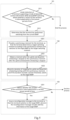
- FIG. 5 another implementation of instructing the terminal with which the BWP switching error is occurred to switch to the target BWP is provided, and a schematic diagram of the implementation is illustrated in Fig. 5 .
- Step 1011 in a case that the working bandwidth of the network device is within the current BWP, following operations are performed on each terminal communicating with the network device: under detection of the terminal supporting the mode of downlink control information (DCI) based BWP switching, whether the service of the terminal is interrupted within a first preset period of time is detected, if the service of the terminal is interrupted within the first preset period of time, step 1012 is performed, otherwise the process of the BWP switching method in the present application stops.
- DCI downlink control information
- Step 1012 it is determined that the terminal has performed switching from the current BWP. If it is determined that the terminal has performed switching from the current BWP, step 1021 is performed.
- Step 1021 a synchronous moment is provided for the terminal, so that the terminal determines a target switching moment according to the synchronous moment, and the terminal switches to the target BWP at the target switching moment.
- Step 1022 the moment when the uplink and downlink scheduling is stopped is obtained as the synchronous moment after the uplink and downlink scheduling is stopped.
- Step 1023 the duration of stopping the uplink and downlink scheduling is recorded starting with the synchronous moment, and if the duration exceeds the preset threshold, it switches to the target BWP.
- Step 1031 after the network device switches to the target BWP at the target switching moment, whether a service of the terminal is interrupted within a second preset period of time is detected, if it is determined that the service of the terminal is interrupted within the second preset period of time, then step 1032 is performed, otherwise the entire process is ended.
- the present embodiment further includes, after step 1023, performing step 1031, namely, whether the service of the terminal is interrupted within the second preset period of time is detected, the second preset period of time may include the current detection moment, and the detection manner is similar to the manner of step 1011.
- Step 1032 a reconfiguration message is issued to the terminal so that the terminal switches to the target BWP, wherein the reconfiguration message includes identity information of the target BWP.
- the network device may issue the reconfiguration message, the reconfiguration message includes: an BWP identity for first active of downlink firstActiveDownlinkBWP-Id and an BWP identity for first active of uplink firstActiveUplinkBWP-Id.
- a format of the reconfiguration message may use DCI1_0.
- Step 1031 and step 1032 are two sub-steps of step 103, as illustrated in Fig. 5 .
- the terminal is detected again, if it is detected that all services of the terminal are still interrupted, the network device forces the terminal to perform BWP switching, and thus it is guaranteed that the BWP of the terminal and the BWP of the network device are consistent.
- FIG. 6 another implementation of instructing the terminal with which the BWP switching error is occurred to switch to the target BWP is provided, and a schematic diagram of the implementation is illustrated in Fig. 6 .
- Step 1011 in a case that the working bandwidth of the network device is within the current BWP, following operations are performed on each terminal communicating with the network device: under detection of the terminal supporting the mode of downlink control information (DCI) based BWP switching, whether the service of the terminal is interrupted within a first preset period of time is detected, if the service of the terminal is interrupted within the first preset period of time, step 1012 is performed, otherwise the process of the BWP switching method in the present application stops.
- DCI downlink control information
- Step 1012 it is determined that the terminal has performed switching from the current BWP. Step 1021' is performed.
- Step 1021' a reconfiguration message is issued to the terminal so that the terminal switches to the target BWP, wherein the reconfiguration message includes identity information of the target BWP.
- the network device may issue the reconfiguration message, the reconfiguration message includes: an BWP identity for first active of downlink firstActiveDownlinkBWP-Id and an BWP identity for first active of uplink firstActiveUplinkBWP-Id.
- a format of the reconfiguration message may use DCI1_0.
- the BWP is forced to be switched, so that the BWP of the terminal and the BWP of the network device are consistent.
- the target BWP of the terminal may be the configured firstActiveDownlinkBWP-Id and firstActiveUplinkBWP-Id.
- Step 1022' the network device is controlled to switch to the target BWP.
- the first active BWP is used as the target BWP; and the network device is controlled to switch to the target BWP. If the BWP of the network device has been within the first active BWP, and in order to guarantee that the BWP of the network device is consistent with the BWP of the terminal, switching may be performed again.
- the network device may stop the uplink and downlink scheduling for the terminal, and after the terminal switches to the target BWP, the network device recovers the uplink and downlink scheduling for the terminal.
- the network device directly forces the terminal to switch the BWP, and the switching manner is simple.
- An embodiment of the present application further relates to a network device, a structural block diagram thereof is illustrated in Fig. 7 , and the network device includes: at least one processor 201; and a memory 202 in communication connection with the at least one processor 201; wherein the memory 202 stores instructions executable by the at least one processor 201, and the instructions, when executed by the at least one processor 201, cause the at least one processor 201 to implement the above channel scene recognition method.
- the memory 202 and the processor 201 are connected through a bus, the bus may include any number of interconnected buses and bridges, and the bus links various circuits of one or more processors and the memory 202.
- the bus may also link various other circuits such as a peripheral device, a voltage stabilizer and a power management circuit, which are well-known in the art and therefore, will not be further described herein.
- a bus interface provides an interface between the bus and a transceiver.
- the transceiver may be an element or a plurality of elements, for example, a plurality of receivers and transmitters, which provide units for communicating with various other devices on a transmission medium.
- Data processed by the processor 201 is transmitted on a wireless medium through an antenna, further, the antenna further receives data and transmits the data to the processor 201.
- the processor 201 is responsible for managing the bus and general processing, and may further provide various functions, including timing, a peripheral interface, voltage regulation, power supply management and other control functions.
- the memory 202 may be configured to store data used when the processor performs operations.
- An embodiment of the present application relates to a computer-readable storage medium having stored thereon a computer program, which, when executed by a processor, implementing the above channel scene recognition method.
- a storage medium includes a plurality of instructions so as to cause one device (which may be a single chip microcomputer, a chip or the like) or a processor to implement all or some steps in the method according to the embodiments of the present application.
- the above storage medium includes: a U disk, a mobile hard disk drive, a read-only memory (ROM), a random access memory (RAM), a diskette, an optical disc or various media capable of storing program code.
Landscapes
- Engineering & Computer Science (AREA)
- Signal Processing (AREA)
- Computer Networks & Wireless Communication (AREA)
- Quality & Reliability (AREA)
- Mobile Radio Communication Systems (AREA)
- Data Exchanges In Wide-Area Networks (AREA)
Abstract
Description
- The present application is proposed based on and claims priority to the
Chinese Patent Application No. 2021107279307, filed on June 29, 2021 - Embodiments of the present application relate to the technical field of 5G communications, in particular to a BWP switching method, a network device, and a storage medium.
- In a 5G new radio (NR) system, a system bandwidth, namely a bandwidth of a carrier wave, may become quite large (for example, 200 MHz or 400 MHz), some terminals have a limited capacity and cannot support a large bandwidth, so a network device will configure a bandwidth part (BWP) for the terminals, for example, 20 MHz, and the terminals may communicate with the network device over the configured BWP. The network device may configure a plurality of BWPs for the terminals, some of which have narrower bandwidths and others have wider bandwidths. Besides, at the same time, one terminal can have only one active BWP, the terminal can receive or send data only over the active BWP. If the terminal needs to transmit a large amount of data, the network device may instruct the terminal to switch to a BWP with a broad bandwidth; and if the terminal needs to transmit a small amount of data, the network device may instruct the terminal again to switch to a BWP with a narrow bandwidth.
- The terminal may perform BWP switching through instruction of downlink control information (DCI), however, there is misdetection or false detection when detecting DCI by the terminal, which will enter a BWP switching process unilaterally, while the network device side does not configure a corresponding BWP for the terminal, resulting in interruption of a service of the terminal.
- In a first aspect, an embodiment of the present application provides a BWP switching method, applied to a network device and including: in a case that a working bandwidth of a network device is within a current BWP and a terminal that has performed switching from the current BWP is detected, determining that a BWP switching error is occurred with the terminal that has performed switching from the current BWP; and instructing the terminal with which the BWP switching error is occurred to switch to a target BWP and controlling the network device to switch to the target BWP.
- In a second aspect, an embodiment of the present application further provides a network device, including: at least one processor; and a memory in communication connection with the at least one processor; wherein the memory stores instructions executable by the at least one processor, and the instructions are executed by the at least one processor so as to cause the at least one processor to implement the above BWP switching method.
- In a third aspect, an embodiment of the present application further provides a computer storage medium having stored thereon a computer program, which, when executed by a processor, implementing the above BWP switching method.
-
-
Fig. 1 is a flowchart of a BWP switching method provided according to an embodiment of the present application. -
Fig. 2 is a schematic diagram of specific implementation of detecting whether a terminal has performed switching from a current BWP provided according to an embodiment of the present application. -
Fig. 3 is a schematic diagram of specific implementation of instructing a terminal with which a BWP switching error is occurred to switch to a target BWP provided according to an embodiment of the present application. -
Fig. 4 is a schematic diagram of specific implementation of a manner for providing a synchronous moment for the terminal provided according to an embodiment of the present application. -
Fig. 5 is a schematic diagram of an implementation of instructing a terminal with which a BWP switching error is occurred to switch to a target BWP provided according to an embodiment of the present application. -
Fig. 6 is a schematic diagram of an implementation of instructing a terminal with which a BWP switching error is occurred to switch to a target BWP provided according to an embodiment of the present application. -
Fig. 7 is a structural block diagram of a network device provided according to an embodiment of the present application. - Main objective of embodiments of the present application is providing a BWP switching method, a network device, and a storage medium, by which a BWP of a terminal may be adjusted for a BWP switching error of the terminal, so the BWP of the terminal keeps consistent with a BWP of a network device side, and thus stability of a service of the terminal is improved.
- To make the objective, technical solutions and advantages of the embodiments of the present application clearer, the following describes the embodiments of the present application in detail with reference to accompanying drawings. Those ordinarily skilled in the art may understand that although many technical details have been provided in the embodiments of the present application to make readers better understand the present application, the technical solutions that the present application claims to protect may still be implemented without such technical details and various changes and modifications based on the following embodiments. Division of the following embodiments is for the purpose of convenient description but is not to constitute any limitation on specific implementations of the present application, and all the embodiments may be combined mutually or refer to one another under the premise of non-contradictory.
- A 5G protocol may support BWP switching of the terminal, there are two common manners for BWP switching of the terminal, namely, one manner of BWP switching through radio resource control (RRC) reconfiguration signaling and the other manner of BWP switching through DCI. BWP switching based on RRC is used for enabling user equipment (UE) to immediately enter a proper BWP once the UE completes initial access and enters an RRC connected state or an RRC reconfiguration or a activation of secondary cell (Scell) so as to perform transceiving of a service instead of remaining on an initial BWP. During the initial access of the UE, the UE keeps using the initial BWP. Once the initial access is completed, the UE enters the RRC connected state, a base station may activate a BWP other than the initial BWP through firstActiveDownlinkBWP-Id and firstActiveUplinkBWP-Id, a bandwidth of the BWP is usually larger than that of the initial BWP.
- If the terminal switches BWP by a DCI issued by the network device, the terminal may switch from a current BWP, when there is misdetection of DCI or false detection of DCI by the terminal. Due to that the network device does not issue the DCI actually, namely the terminal enters the BWP switching process unilaterally, while the network device remains in the current BWP state, an interruption of the service of the terminal is caused. For example, a working bandwidth of the network device is within BWP1, a working bandwidth of the terminal is also within BWP1, the current BWP refers to the BWP1, when the terminal enters the BWP switching process unilaterally, while the network device remains in the current BWP state, namely the working bandwidth of the network device remains within the BWP1, and now the working bandwidth of the terminal is within BWP2, resulting in interruption of the service of the terminal at this moment.
- An embodiment of the present application relates to a BWP switching method, implemented by a network device, the network device is, for example, a base station, and a flow of the method is illustrated in
Fig. 1 . - Step 101: in a case that a working bandwidth of a network device is within a current BWP and a terminal that has performed switching from the current BWP is detected, it is determined that a BWP switching error is occurred with the terminal that has performed switching from the current BWP.
- Specifically, the terminal may be a mobile device, such as a mobile phone, and the terminal may also be a computer, an Internet of Things device and the like. The base station may communicate with a plurality of terminals and may perform the following operations on each terminal in communication: the network device may detect whether the terminal supports a mode of DCI switching BWP, if the terminal does not support the mode of DCI switching BWP, a process of the BWP switching method of the present embodiment ends, and if the terminal supports the mode of DCI switching BWP, whether the terminal has performed switching from the current BWP may be further detected.
- A manner of detecting whether the terminal has performed switching from the current BWP may be determined based on whether a service of the terminal is normal. As the terminal receives data only over an active BWP, if the terminal switches to a false BWP, consequently, the active BWP is inconsistent with the BWP of the network device, resulting in interruption of the service of the terminal, for example, call drop.
- It needs to be noted that DCI misdetection or DCI false detection by the terminal leads to the BWP switching error occurred with the terminal, and if the terminal does not support the mode of DCI switching BWP, the subsequent process is not needed. The method of the present embodiment is implemented by the network device communicating with the terminal, and the terminal in communication supports the mode of DCI switching BWP.
- Step 102: the terminal with which the BWP switching error is occurred is instructed to switch to a target BWP, and the network device is controlled to switch to the target BWP.
- Specifically, if the terminal is configured with a plurality of dedicated BWPs and the terminal supports the mode of DCI switching BWP, the network device may instruct the terminal to switch to the target BWP in a manner of issuing DCI, where the target BWP may be a preset default BWP, and at the same time, the network device is controlled to switch to the default BWP. The default BWP is a preset BWP with a small bandwidth.
- It needs to be noted that after a BWP state of the network device is consistent with a BWP state of the terminal, the process based on DCI switching BWP may be recovered.
- According to the BWP switching method provided by the present application, if the BWP of the terminal is inconsistent with the BWP of the network device, the service between the terminal and the network device may be interrupted, and the use of the terminal is affected; in a case that the working bandwidth of the network device is within the current BWP and it is detected that the terminal has performed switching from the current BWP, it is determined that the BWP switching error is occurred with the terminal, the network device thus instructs the terminal to switch to the target terminal, the network device switches its BWP to the target BWP as well, such that the BWP of the network device is consistent with the BWP of the terminal, avoiding the interruption of the service of the terminal. As the BWP switching error occurred with the terminal may be discovered in time, the BWP state of the terminal may be optimized in time, stability of BWP switching is improved, call drop is avoided, and thus the stability of the service of the terminal is improved.
- In an embodiment, a specific implementation of detecting whether the terminal has performed switching from the current BWP is provided, and a schematic diagram of this implementation is illustrated in
Fig. 2 . - Step 1011: in a case that the working bandwidth of the network device is within the current BWP, following operations are performed on each terminal communicating with the network device: under detection of the terminal supporting the mode of downlink control information (DCI) based BWP switching, whether the service of the terminal is interrupted within a first preset period of time is detected, if the service of the terminal is interrupted within the first preset period of time,
step 1012 is performed, otherwise the process of the BWP switching method in the present application stops. - In an example, the process of detecting whether the service of the terminal is interrupted within the first preset period of time is: under detection of the terminal being in a discontinuous transmission (DTX) state at a moment T, whether the service of the terminal at a moment T-1 is normal is detected, if normal, then the service of the terminal is interrupted within the first preset period of time is determined, otherwise the service of the terminal is normal within the first preset period of time is determined, wherein T is an integer greater than 1.
- Specifically, the first preset period of time includes the moment T and the moment T-1, the moment T may be a current detection moment, and the moment T-1 may be a previous detection moment. Under detection of the terminal being in the DTX state at the moment T, it indicates that the service of the terminal is interrupted currently; and at this moment, whether the service of the terminal is normal at the previous moment, namely the moment T-1, is detected, if the service of the terminal is normal at the moment T-1, namely the terminal is not in the DTX state, it may be determined that the service of the terminal is normal. When it is determined that the service of the terminal is normal at the moment T-1 and is interrupted at the moment T, it may be determined that the terminal has performed switching from the current BWP.
- Step 1012: it is determined that the terminal has performed switching from the current BWP; and
step 102 is performed. - Step 102: the terminal with which the BWP switching error is occurred is instructed to switch to a target BWP, and the network device is controlled to switch to the target BWP.
- In the present embodiment, by detecting the service of the terminal, the network device determines whether the terminal has performed switching from the current BWP, if the terminal is on a correct active BWP, the service of the terminal may not be interrupted, based on this, in the embodiment, with a detection result of the current detection moment and a detection result of the previous detection moment, whether the terminal has performed switching from the current BWP may be determined accurately, avoiding misjudgment for the terminal that has performed false switching from the current BWP, and improving detection accuracy.
- In an embodiment, a specific implementation of instructing the terminal with which the BWP switching error is occurred to switch to the target BWP is provided, and a schematic diagram of the implementation is illustrated in
Fig. 3 . - Step 1011: in a case that the working bandwidth of the network device is within the current BWP, following operations are performed on each terminal communicating with the network device: under detection of the terminal supporting the mode of downlink control information (DCI) based BWP switching, whether the service of the terminal is interrupted within a first preset period of time is detected, if the service of the terminal is interrupted within the first preset period of time,
step 1012 is performed, otherwise the process of the BWP switching method in the present application stops. - Step 1012: it is determined that the terminal has performed switching from the current BWP.
Step 1021 is performed. - Step 1021: a synchronous moment is provided for the terminal, so that the terminal determines a target switching moment according to the synchronous moment, and the terminal switches to the target BWP at the target switching moment.
- Specifically, the target BWP may be set as a default BWP, and a BWP fall-back mechanism is started in a manner of providing the synchronous moment for the terminal. For example, instruction information may be issued to the terminal, the terminal uses a moment when the instruction information is received as the synchronous moment, and both the terminal and the network device use the synchronous moment as a timekeeping start point and simultaneously trigger the fall-back mechanism when reaching the preset target switching moment to fall back to the default BWP, so that the BWP of the terminal and the BWP of the network device keep consistent.
- In another example, the manner of the providing the synchronous moment for the terminal may use a manner in
step S 1, namely, a manner of a schematic diagram ofFig. 4 of the present embodiment. - Step S1: uplink and downlink scheduling is stopped, so that the terminal uses a moment when the uplink and downlink scheduling is stopped as the synchronous moment and determines the target switching moment according to the synchronous moment.
- Specifically, the network device stops the uplink and downlink scheduling. As the network device stops the uplink and downlink scheduling, the terminal may use a moment when downlink control information for scheduling the terminal is not received as the synchronous moment, and the terminal uses the synchronous moment as the timekeeping start point and switches the BWP when reaching the target switching moment. For example, the duration of stopping the uplink and downlink scheduling may be counted from the synchronization moment, for example, a bwp-InactivityTimer is started for counting, and if the duration exceeds a preset threshold, it indicates that the target switching moment is reached.
- Step 1022: the moment when the uplink and downlink scheduling is stopped is obtained as the synchronous moment after the uplink and downlink scheduling is stopped.
- Similar to a process of the terminal obtaining the synchronous moment as described in
step 1021, the network device obtains the moment when the uplink and downlink scheduling is stopped as the synchronous moment. - Step 1023: the duration of stopping the uplink and downlink scheduling is recorded starting with the synchronous moment, and if the duration exceeds the preset threshold, it switches to the target BWP.
- Specifically, the network device records, starting with the synchronous moment, the duration of stopping the scheduling, and if the duration exceeds the preset threshold, it indicates that the target switching moment is reached. Likewise, counting of the duration may be implemented through the bwp-InactivityTimer. In other words, starting with the synchronous moment, the bwp-InactivityTimer is started, if the duration recorded by the bwp-InactivityTimer exceeds the preset threshold, then the terminal and the network device enter the BWP fall-back mechanism synchronously and both fall back to the corresponding default BWP.
- In the present embodiment, by providing the synchronous moment for the terminal by the network device, the terminal and the network device may determine the target switching moment based on the synchronous moment, the terminal and the network device switch to the target BWP synchronously when reaching the target switching moment, and it may be guaranteed that the BWP states of the both are consistent due to synchronous switching. Besides, the synchronous moment is provided for the terminal in a manner of stopping the uplink and downlink scheduling, so that no service is performed between the terminal and the network device during switching, and influence on the service of the terminal is reduced.
- In an embodiment, another implementation of instructing the terminal with which the BWP switching error is occurred to switch to the target BWP is provided, and a schematic diagram of the implementation is illustrated in
Fig. 5 . - Step 1011: in a case that the working bandwidth of the network device is within the current BWP, following operations are performed on each terminal communicating with the network device: under detection of the terminal supporting the mode of downlink control information (DCI) based BWP switching, whether the service of the terminal is interrupted within a first preset period of time is detected, if the service of the terminal is interrupted within the first preset period of time,
step 1012 is performed, otherwise the process of the BWP switching method in the present application stops. - Step 1012: it is determined that the terminal has performed switching from the current BWP. If it is determined that the terminal has performed switching from the current BWP,
step 1021 is performed. - Step 1021: a synchronous moment is provided for the terminal, so that the terminal determines a target switching moment according to the synchronous moment, and the terminal switches to the target BWP at the target switching moment.
- Step 1022: the moment when the uplink and downlink scheduling is stopped is obtained as the synchronous moment after the uplink and downlink scheduling is stopped.
- Step 1023: the duration of stopping the uplink and downlink scheduling is recorded starting with the synchronous moment, and if the duration exceeds the preset threshold, it switches to the target BWP.
- Step 1031: after the network device switches to the target BWP at the target switching moment, whether a service of the terminal is interrupted within a second preset period of time is detected, if it is determined that the service of the terminal is interrupted within the second preset period of time, then step 1032 is performed, otherwise the entire process is ended.
- Specifically, in order to further guarantee the consistency of the BWP of the terminal and the BWP of the network device, the present embodiment further includes, after
step 1023, performingstep 1031, namely, whether the service of the terminal is interrupted within the second preset period of time is detected, the second preset period of time may include the current detection moment, and the detection manner is similar to the manner ofstep 1011. - After the terminal and the network device switch to the target BWP, whether all services of the terminal are in the DTX state is detected, and if yes, it indicates that the BWP of the terminal is different from the BWP of the network device currently.
- Step 1032: a reconfiguration message is issued to the terminal so that the terminal switches to the target BWP, wherein the reconfiguration message includes identity information of the target BWP.
- The network device may issue the reconfiguration message, the reconfiguration message includes: an BWP identity for first active of downlink firstActiveDownlinkBWP-Id and an BWP identity for first active of uplink firstActiveUplinkBWP-Id. A format of the reconfiguration message may use DCI1_0. After the terminal receives the reconfiguration message, the BWP is forced to be switched again, so that the BWP of the terminal and the BWP of the network device are consistent. In this step, a target BWP is reset, for example, the target BWP of the terminal may be the configured firstActiveDownlinkBWP-Id and firstActiveUplinkB WP-Id.
-
Step 1031 andstep 1032 are two sub-steps ofstep 103, as illustrated inFig. 5 . - In the present embodiment, the terminal is detected again, if it is detected that all services of the terminal are still interrupted, the network device forces the terminal to perform BWP switching, and thus it is guaranteed that the BWP of the terminal and the BWP of the network device are consistent.
- In an embodiment, another implementation of instructing the terminal with which the BWP switching error is occurred to switch to the target BWP is provided, and a schematic diagram of the implementation is illustrated in
Fig. 6 . - Step 1011: in a case that the working bandwidth of the network device is within the current BWP, following operations are performed on each terminal communicating with the network device: under detection of the terminal supporting the mode of downlink control information (DCI) based BWP switching, whether the service of the terminal is interrupted within a first preset period of time is detected, if the service of the terminal is interrupted within the first preset period of time,
step 1012 is performed, otherwise the process of the BWP switching method in the present application stops. - Step 1012: it is determined that the terminal has performed switching from the current BWP. Step 1021' is performed.
- Step 1021': a reconfiguration message is issued to the terminal so that the terminal switches to the target BWP, wherein the reconfiguration message includes identity information of the target BWP.
- The network device may issue the reconfiguration message, the reconfiguration message includes: an BWP identity for first active of downlink firstActiveDownlinkBWP-Id and an BWP identity for first active of uplink firstActiveUplinkBWP-Id. A format of the reconfiguration message may use DCI1_0. After the terminal receives the reconfiguration message, the BWP is forced to be switched, so that the BWP of the terminal and the BWP of the network device are consistent. The target BWP of the terminal may be the configured firstActiveDownlinkBWP-Id and firstActiveUplinkBWP-Id.
- Step 1022': the network device is controlled to switch to the target BWP.
- If the BWP of the network device is not within a preset first active BWP, the first active BWP is used as the target BWP; and the network device is controlled to switch to the target BWP. If the BWP of the network device has been within the first active BWP, and in order to guarantee that the BWP of the network device is consistent with the BWP of the terminal, switching may be performed again.
- It needs to be noted that before the network device issues the reconfiguration message, the network device may stop the uplink and downlink scheduling for the terminal, and after the terminal switches to the target BWP, the network device recovers the uplink and downlink scheduling for the terminal.
- In the present embodiment, the network device directly forces the terminal to switch the BWP, and the switching manner is simple.
- An embodiment of the present application further relates to a network device, a structural block diagram thereof is illustrated in
Fig. 7 , and the network device includes: at least oneprocessor 201; and amemory 202 in communication connection with the at least oneprocessor 201; wherein thememory 202 stores instructions executable by the at least oneprocessor 201, and the instructions, when executed by the at least oneprocessor 201, cause the at least oneprocessor 201 to implement the above channel scene recognition method. - The
memory 202 and theprocessor 201 are connected through a bus, the bus may include any number of interconnected buses and bridges, and the bus links various circuits of one or more processors and thememory 202. The bus may also link various other circuits such as a peripheral device, a voltage stabilizer and a power management circuit, which are well-known in the art and therefore, will not be further described herein. A bus interface provides an interface between the bus and a transceiver. The transceiver may be an element or a plurality of elements, for example, a plurality of receivers and transmitters, which provide units for communicating with various other devices on a transmission medium. Data processed by theprocessor 201 is transmitted on a wireless medium through an antenna, further, the antenna further receives data and transmits the data to theprocessor 201. - The
processor 201 is responsible for managing the bus and general processing, and may further provide various functions, including timing, a peripheral interface, voltage regulation, power supply management and other control functions. Thememory 202 may be configured to store data used when the processor performs operations. - An embodiment of the present application relates to a computer-readable storage medium having stored thereon a computer program, which, when executed by a processor, implementing the above channel scene recognition method.
- Those skilled in the art may understand that implementation of all or some steps in the method in the above embodiment may be completed by instructing related hardware through a program, and the program is stored in a storage medium and includes a plurality of instructions so as to cause one device (which may be a single chip microcomputer, a chip or the like) or a processor to implement all or some steps in the method according to the embodiments of the present application. The above storage medium includes: a U disk, a mobile hard disk drive, a read-only memory (ROM), a random access memory (RAM), a diskette, an optical disc or various media capable of storing program code.
- Those ordinarily skilled in the art may understand that the above implementations are specific embodiments for implementing the present application. In actual applications, various changes may be made in form or details without departing from the spirit and the scope of the present application.
Claims (10)
- A BWP switching method, applied to a network device, the method comprising:determining that, in a case that a working bandwidth of a network device is within a current BWP and if a terminal that has performed switching from the current BWP is detected, a BWP switching error is occurred with the terminal that has performed switching from the current BWP; andinstructing the terminal with which the BWP switching error is occurred to switch to a target BWP and controlling the network device to switch to the target BWP.
- The BWP switching method of claim 1, wherein in a case that the working bandwidth of the network device is within the current BWP and if the terminal that has performed switching from the current BWP is detected, comprising:performing following operations on each terminal communicating with the network device, in a case that the working bandwidth of the network device is within the current BWP: detecting whether a service of the terminal is interrupted within a first preset period of time, under detection of the terminal supporting the mode of downlink control information (DCI) based BWP switching; anddetermining that the terminal has performed switching from the current BWP, if it is determined that the service of the terminal is interrupted within the first preset period of time.
- The BWP switching method of claim 2, wherein detecting whether the service of the terminal is interrupted within the first preset period of time comprising:
detecting whether the service of the terminal is normal at a moment T-1, under detection of the terminal being in a discontinuous transmission (DTX) state at a moment T; if normal, then determining that the service of the terminal is interrupted within the first preset period of time; otherwise, determining that the service of the terminal is normal within the first preset period of time, wherein T is an integer greater than 1. - The BWP switching method of any one of claims 1 to 3, wherein instructing the terminal with which the BWP switching error is occurred to switch to the target BWP comprising:
providing a synchronous moment for the terminal, so that the terminal determines a target switching moment according to the synchronous moment, and the terminal switches to the target BWP at the target switching moment. - The BWP switching method of claim 4, wherein providing synchronous moment information for the terminal comprising:
stopping uplink and downlink scheduling, so that the terminal uses a moment when the uplink and downlink scheduling is stopped as the synchronous moment and determines the target switching moment according to the synchronous moment. - The BWP switching method of claim 5, wherein controlling the network device to switch to the target BWP comprising:obtaining the moment when the uplink and downlink scheduling is stopped as the synchronous moment after the uplink and downlink scheduling is stopped; andrecording a duration of stopping the uplink and downlink scheduling starting with the synchronous moment, and if the duration exceeds a preset threshold, switching to the target BWP.
- The BWP switching method of any one of claims 4 to 6, further comprising:
detecting whether a service of the terminal is interrupted within a second preset period of time, after the network device switches to the target BWP at the target switching moment, and issuing a reconfiguration message to the terminal so that the terminal switches to the target BWP, if it is determined that the service of the terminal is interrupted within the second preset period of time, wherein the reconfiguration message comprises identity information of the target BWP. - The BWP switching method of any one of claims 1 to 3, wherein instructing the terminal with which the BWP switching error is occurred to switch to the target BWP comprising:
issuing a reconfiguration message to the terminal so that the terminal switches to the target BWP, wherein the reconfiguration message comprises identity information of the target BWP. - A network device, comprising:at least one processor; anda memory in communication connection with the at least one processor; whereinthe memory stores instructions executable by the at least one processor, and the instructions, when executed by the at least one processor, cause the at least one processor to implement the BWP switching method of any one of claims 1 to 8.
- A computer storage medium having stored thereon a computer program, which, when executed by a processor, implementing the BWP switching method of any one of claims 1 to 8.
Applications Claiming Priority (2)
| Application Number | Priority Date | Filing Date | Title |
|---|---|---|---|
| CN202110727930.7A CN115551022A (en) | 2021-06-29 | 2021-06-29 | Method, network equipment and storage medium for switching BWP |
| PCT/CN2022/101920 WO2023274232A1 (en) | 2021-06-29 | 2022-06-28 | Bwp switching method, network device, and storage medium |
Publications (2)
| Publication Number | Publication Date |
|---|---|
| EP4354996A1 true EP4354996A1 (en) | 2024-04-17 |
| EP4354996A4 EP4354996A4 (en) | 2024-10-30 |
Family
ID=84690343
Family Applications (1)
| Application Number | Title | Priority Date | Filing Date |
|---|---|---|---|
| EP22832046.1A Pending EP4354996A4 (en) | 2021-06-29 | 2022-06-28 | BWP SWITCHING METHOD, NETWORK DEVICE AND STORAGE MEDIUM |
Country Status (5)
| Country | Link |
|---|---|
| US (1) | US20250081171A1 (en) |
| EP (1) | EP4354996A4 (en) |
| JP (1) | JP7688734B2 (en) |
| CN (1) | CN115551022A (en) |
| WO (1) | WO2023274232A1 (en) |
Families Citing this family (2)
| Publication number | Priority date | Publication date | Assignee | Title |
|---|---|---|---|---|
| CN116684975A (en) * | 2023-06-27 | 2023-09-01 | 浪潮通信技术有限公司 | Target BWP handover detection method and device for user terminal |
| CN118450447B (en) * | 2023-11-25 | 2025-04-15 | 荣耀终端股份有限公司 | A communication method, terminal device and chip system in wireless network |
Family Cites Families (56)
| Publication number | Priority date | Publication date | Assignee | Title |
|---|---|---|---|---|
| US11716715B2 (en) * | 2017-07-28 | 2023-08-01 | Lg Electronics Inc. | Method of performing BWP operation in wireless communication system and an apparatus therefor |
| EP3661258B1 (en) * | 2017-07-28 | 2024-11-06 | Beijing Xiaomi Mobile Software Co., Ltd. | Methods and a terminal for acquiring control information |
| US10873866B2 (en) * | 2017-09-27 | 2020-12-22 | Electronics And Telecommunications Research Institute | Method for managing radio resources in communication system and apparatus for the same |
| WO2019062867A1 (en) * | 2017-09-28 | 2019-04-04 | Telefonaktiebolaget Lm Ericsson (Publ) | Switching of bandwidth parts in wireless communication network |
| US11277862B2 (en) * | 2017-10-26 | 2022-03-15 | Comcast Cable Communications, Llc | Activation and deactivation of configured grant |
| US10887073B2 (en) * | 2017-10-26 | 2021-01-05 | Ofinno, Llc | Activation and deactivation of bandwidth part |
| CN109788553A (en) * | 2017-11-10 | 2019-05-21 | 华为技术有限公司 | A kind of bandwidth switching method and device |
| KR102352684B1 (en) * | 2017-11-16 | 2022-01-18 | 삼성전자주식회사 | Method and apparatus for wireless communication in wireless communication system |
| KR20200111719A (en) * | 2018-01-19 | 2020-09-29 | 광동 오포 모바일 텔레커뮤니케이션즈 코포레이션 리미티드 | Timer-based bandwidth part switching method, terminal device and network device |
| WO2019191262A1 (en) * | 2018-03-30 | 2019-10-03 | Ofinno, Llc | Bandwidthpart (bwp) switching during beam failure recovery |
| CN112737740A (en) * | 2018-04-04 | 2021-04-30 | 华为技术有限公司 | Method and device for controlling timer |
| US12167448B2 (en) * | 2018-05-09 | 2024-12-10 | Interdigital Patent Holdings, Inc. | Channel access with a new radio unlicensed serving cell |
| US10880949B2 (en) * | 2018-05-15 | 2020-12-29 | Comcast Cable Communications, Llc | Multiple active bandwidth parts |
| EP3876642B1 (en) * | 2018-05-21 | 2025-09-17 | Comcast Cable Communications LLC | Random access procedures using multiple active bandwidth parts |
| CN110536360B (en) * | 2018-05-23 | 2023-03-31 | 中国移动通信有限公司研究院 | BWP switching method, device and storage medium based on downlink control signaling |
| US10778318B2 (en) * | 2018-08-03 | 2020-09-15 | Ofinno, Llc | Bandwidth parts switching in beam failure recovery procedure |
| CN110831170B (en) * | 2018-08-09 | 2022-07-29 | 华为技术有限公司 | Communication method and device |
| WO2020030020A1 (en) * | 2018-08-10 | 2020-02-13 | 华为技术有限公司 | Bandwidth part switching method, method for indicating bandwidth part switching, terminal, and network apparatus |
| CN110831130B (en) * | 2018-08-10 | 2021-10-22 | 华为技术有限公司 | Data transmission method and device |
| CN110858958B (en) * | 2018-08-23 | 2021-09-07 | 华为技术有限公司 | V2X communication method and device |
| CN110891313B (en) * | 2018-09-10 | 2022-08-02 | 维沃移动通信有限公司 | Information transmission method, network equipment and terminal |
| US11956809B2 (en) * | 2018-09-26 | 2024-04-09 | Beijing Xiaomi Mobile Software Co., Ltd. | Resource determining methods and apparatuses |
| CN112970212B (en) * | 2018-11-05 | 2024-06-21 | 诺基亚技术有限公司 | Data transmission using part of bandwidth |
| WO2020096987A2 (en) * | 2018-11-05 | 2020-05-14 | Yuhan Zhou | Mechanisms for bandwidth part (bwp) switching in a new radio (nr) network |
| US11095419B2 (en) * | 2019-01-02 | 2021-08-17 | Ofinno, Llc | Simultaneous bandwidth parts switching |
| CN113455073B (en) * | 2019-01-04 | 2024-08-13 | 苹果公司 | Accessing communication channels using different communication systems |
| WO2020146853A1 (en) * | 2019-01-11 | 2020-07-16 | Apple Inc. | User equipment processing time relaxation for multi-dci nc-jt pdsch reception |
| WO2020145722A1 (en) * | 2019-01-11 | 2020-07-16 | 엘지전자 주식회사 | Method for performing sl communication in consideration of bwp switching in nr v2x, and initial access operation |
| US12389400B2 (en) * | 2019-01-29 | 2025-08-12 | Samsung Electronics Co., Ltd. | Method and device for by-link activation and deactivation for reducing power consumption in next generation mobile communication system |
| US12200775B2 (en) * | 2019-02-15 | 2025-01-14 | Lg Electronics Inc. | Method for transmitting and receiving signal in wireless communication system and apparatus supporting same |
| WO2020167059A1 (en) * | 2019-02-15 | 2020-08-20 | 엘지전자 주식회사 | Method for transmitting and receiving signal in wireless communication system and apparatus supporting same |
| JP7342139B2 (en) * | 2019-02-18 | 2023-09-11 | アップル インコーポレイテッド | Method and system for secondary cell beam recovery |
| KR20210115029A (en) * | 2019-02-22 | 2021-09-24 | 애플 인크. | High-speed enhanced carrier aggregation (CA) radio resource management (RRM) measurements |
| US12232176B2 (en) * | 2019-03-07 | 2025-02-18 | Apple Inc. | Methods for random access channel (RACH) configuration for relay node |
| PT3845011T (en) * | 2019-03-28 | 2023-09-27 | Ofinno Llc | Power-saving active bwp |
| CN113906792B (en) * | 2019-04-02 | 2024-06-21 | 瑞典爱立信有限公司 | Control channel monitoring in wireless communication systems |
| WO2020232566A1 (en) * | 2019-05-17 | 2020-11-26 | 北京小米移动软件有限公司 | Bwp switching method and device, and storage medium |
| WO2021029750A1 (en) * | 2019-08-14 | 2021-02-18 | 삼성전자 주식회사 | Method and device for measurement in wireless communication system |
| CN112399571B (en) | 2019-08-15 | 2024-05-07 | 华为技术有限公司 | A communication method and device |
| CN118590205A (en) * | 2019-08-16 | 2024-09-03 | 联发科技股份有限公司 | Method and device for switching bandwidth part |
| CN114424661B (en) * | 2019-08-17 | 2025-09-23 | 韦勒斯标准与技术协会公司 | Method, device and system for transmitting and receiving a physical uplink shared channel (PUSCH) in a wireless communication system |
| CN115053479B (en) * | 2020-01-16 | 2025-07-29 | 高通股份有限公司 | Monitoring of combined Downlink Control Information (DCI) for scheduling transmissions in multiple cells |
| KR20210092973A (en) * | 2020-01-17 | 2021-07-27 | 삼성전자주식회사 | Method and appratus of starting timers depending on the type of bandwidht part (BWP) in wireless communication systems |
| US12245309B2 (en) * | 2020-01-27 | 2025-03-04 | Nokia Technologies Oy | Beam failure recovery for dormant bandwidth part |
| US12463786B2 (en) * | 2020-02-28 | 2025-11-04 | Qualcomm Incorporated | Bandwidth part (BWP) partition and sub-BWP hopping |
| EP4133879A1 (en) * | 2020-04-09 | 2023-02-15 | Telefonaktiebolaget LM ERICSSON (PUBL) | Handling redirection failures in rrc connection redirection procedure |
| US12446006B2 (en) * | 2020-05-21 | 2025-10-14 | Sharp Kabushiki Kaisha | Method and user equipment for performing sidelink communication |
| CN111629442B (en) * | 2020-05-27 | 2022-09-27 | 展讯通信(上海)有限公司 | BWP mis-switching processing method and device, storage medium and terminal |
| EP4140173B1 (en) * | 2020-05-29 | 2025-08-20 | Apple Inc. | Bandwidth part switching in 5g new radio dual connectivity |
| US12408041B2 (en) * | 2020-06-04 | 2025-09-02 | Nec Corporation | Virtualized RAN slicing with bandwidth parts |
| KR102945900B1 (en) * | 2020-06-05 | 2026-04-01 | 삼성전자주식회사 | Method and apparatus for transmission and reception of downlink control information scheduling data channels in wireless communication system |
| US12245212B2 (en) * | 2020-07-02 | 2025-03-04 | Qualcomm Incorporated | Bandwidth part switching |
| US12108377B2 (en) * | 2020-10-23 | 2024-10-01 | Apple Inc. | Enhancement to bandwidth part (BWP) switching for secondary cell (SCell) |
| US12542629B2 (en) * | 2021-02-11 | 2026-02-03 | Qualcomm Incorporated | Resource signal reception capability for multiple component carriers |
| CN112714481B (en) * | 2021-03-26 | 2021-07-02 | 新华三技术有限公司 | BWP switching method and base station equipment |
| CN117378260A (en) * | 2021-05-25 | 2024-01-09 | 高通股份有限公司 | Transport Configuration Indicator Status Applicability Before Acknowledgment |
-
2021
- 2021-06-29 CN CN202110727930.7A patent/CN115551022A/en active Pending
-
2022
- 2022-06-28 EP EP22832046.1A patent/EP4354996A4/en active Pending
- 2022-06-28 WO PCT/CN2022/101920 patent/WO2023274232A1/en not_active Ceased
- 2022-06-28 US US18/574,722 patent/US20250081171A1/en active Pending
- 2022-06-28 JP JP2023580502A patent/JP7688734B2/en active Active
Also Published As
| Publication number | Publication date |
|---|---|
| EP4354996A4 (en) | 2024-10-30 |
| JP2024522917A (en) | 2024-06-21 |
| US20250081171A1 (en) | 2025-03-06 |
| CN115551022A (en) | 2022-12-30 |
| JP7688734B2 (en) | 2025-06-04 |
| WO2023274232A1 (en) | 2023-01-05 |
Similar Documents
| Publication | Publication Date | Title |
|---|---|---|
| US12096263B2 (en) | Method and apparatus for fast serving cell activation | |
| EP3836623B1 (en) | Cell handover method and apparatus, rrc reestablishment method and apparatus, storage medium and user equipment | |
| US10912023B2 (en) | System and method for activating and deactivating multiple secondary cells | |
| EP2914030B1 (en) | Discontinuous reception (drx) mode processing method, user equipment, and base station | |
| KR101975195B1 (en) | Base station and method connecting user equipment thereof | |
| US12507317B2 (en) | Methods and apparatuses for a SCG deactivation mechanism and a SCG activation mechanism in a MR-DC scenario | |
| US12262436B2 (en) | Dual connectivity and carrier aggregation enhancement schemes in wireless communication | |
| EP4354996A1 (en) | Bwp switching method, network device, and storage medium | |
| US20230189092A1 (en) | Method and apparatus for master cell group link recovery considering conditional handover and listen before talk | |
| EP2542013A2 (en) | Discontinuous communication | |
| CN113099737A (en) | Communication method and device | |
| US20240389136A1 (en) | User equipment, base station, and channel access method | |
| CN117440536A (en) | Method for restoring RRC connection performed by user equipment and user equipment | |
| EP4054283A1 (en) | Discontinuous reception configuration method, configuration apparatus, base station, terminal, and storage medium | |
| EP4486008A1 (en) | Method and system for managing source cell connection during a dual active protocol stack (daps) handover | |
| EP4387366A1 (en) | Method for controlling transmission, and related apparatus | |
| US20210250976A1 (en) | Method of determining ambiguous period, terminal and network-side device | |
| US20240172017A1 (en) | Methods and apparatuses for a rlf processing procedure and a phr procedure in a deactivated sn case | |
| CN117425229A (en) | Method for configuring secondary service cell executed by user equipment and user equipment | |
| WO2021063109A1 (en) | Uplink authorization request control method, device, terminal and storage medium | |
| EP4426050A1 (en) | Information reporting method, terminal device, and network side device | |
| US20230232441A1 (en) | Resource selection method and apparatus, and electronic device | |
| EP4712569A1 (en) | Conditional l1l2 mobility | |
| CN111278046A (en) | Voice service processing method and device, storage medium and electronic device | |
| CN113497638B (en) | Information indication methods and related products |
Legal Events
| Date | Code | Title | Description |
|---|---|---|---|
| STAA | Information on the status of an ep patent application or granted ep patent |
Free format text: STATUS: THE INTERNATIONAL PUBLICATION HAS BEEN MADE |
|
| PUAI | Public reference made under article 153(3) epc to a published international application that has entered the european phase |
Free format text: ORIGINAL CODE: 0009012 |
|
| STAA | Information on the status of an ep patent application or granted ep patent |
Free format text: STATUS: REQUEST FOR EXAMINATION WAS MADE |
|
| 17P | Request for examination filed |
Effective date: 20240111 |
|
| AK | Designated contracting states |
Kind code of ref document: A1 Designated state(s): AL AT BE BG CH CY CZ DE DK EE ES FI FR GB GR HR HU IE IS IT LI LT LU LV MC MK MT NL NO PL PT RO RS SE SI SK SM TR |
|
| REG | Reference to a national code |
Ref country code: DE Ref legal event code: R079 Free format text: PREVIOUS MAIN CLASS: H04W0072040000 Ipc: H04L0005000000 |
|
| DAV | Request for validation of the european patent (deleted) | ||
| DAX | Request for extension of the european patent (deleted) | ||
| A4 | Supplementary search report drawn up and despatched |
Effective date: 20241001 |
|
| RIC1 | Information provided on ipc code assigned before grant |
Ipc: H04W 72/0453 20230101ALN20240925BHEP Ipc: H04W 36/00 20090101ALI20240925BHEP Ipc: H04W 36/06 20090101ALI20240925BHEP Ipc: H04L 5/00 20060101AFI20240925BHEP |
|
| STAA | Information on the status of an ep patent application or granted ep patent |
Free format text: STATUS: THE APPLICATION HAS BEEN WITHDRAWN |