EP4354931A1 - Information processing device and method for determining installation position for radio wave reflecting member, and program - Google Patents
Information processing device and method for determining installation position for radio wave reflecting member, and program Download PDFInfo
- Publication number
- EP4354931A1 EP4354931A1 EP22811291.8A EP22811291A EP4354931A1 EP 4354931 A1 EP4354931 A1 EP 4354931A1 EP 22811291 A EP22811291 A EP 22811291A EP 4354931 A1 EP4354931 A1 EP 4354931A1
- Authority
- EP
- European Patent Office
- Prior art keywords
- radio
- wave
- installation
- target
- reflecting member
- Prior art date
- Legal status (The legal status is an assumption and is not a legal conclusion. Google has not performed a legal analysis and makes no representation as to the accuracy of the status listed.)
- Pending
Links
Images




Classifications
-
- H—ELECTRICITY
- H04—ELECTRIC COMMUNICATION TECHNIQUE
- H04W—WIRELESS COMMUNICATION NETWORKS
- H04W16/00—Network planning, e.g. coverage or traffic planning tools; Network deployment, e.g. resource partitioning or cells structures
- H04W16/24—Cell structures
- H04W16/26—Cell enhancers or enhancement, e.g. for tunnels, building shadow
-
- H—ELECTRICITY
- H04—ELECTRIC COMMUNICATION TECHNIQUE
- H04B—TRANSMISSION
- H04B17/00—Monitoring; Testing
- H04B17/30—Monitoring; Testing of propagation channels
- H04B17/309—Measuring or estimating channel quality parameters
-
- H—ELECTRICITY
- H04—ELECTRIC COMMUNICATION TECHNIQUE
- H04W—WIRELESS COMMUNICATION NETWORKS
- H04W16/00—Network planning, e.g. coverage or traffic planning tools; Network deployment, e.g. resource partitioning or cells structures
- H04W16/24—Cell structures
- H04W16/28—Cell structures using beam steering
Definitions
- the present invention relates to an information processing apparatus, method and program for determining an installation position of a radio-wave reflecting member such as a radio-wave reflecting plate which reflects a radio wave in a high frequency band such as a millimeter wave band.
- Patent Literature 1 Japanese Unexamined Patent Publication No. 2010-226695 .
- the necessary number of radio-wave reflecting plate needs to be disposed in appropriate places (for example, wall surfaces of buildings) so that the radio waves reach an area out of line-of-sight against a transmission point such as a base station that transmits the radio waves with a predetermined power.
- a transmission point such as a base station that transmits the radio waves with a predetermined power.
- An information processing apparatus is an information processing apparatus for performing a process of determining an installation position of a radio-wave reflecting member.
- This information processing apparatus comprises a propagation-path setting section for setting plural radio-wave propagation paths each with one reflection between a radio-wave transmission point in a target area and a target reception point located in an area out of line-of-sight against the radio-wave transmission point, based on map information of the target area, a reception-characteristics estimating section for estimating reception characteristics at the target reception point for each of the plural radio-wave propagation paths, and an installation-position determining section for calculating a total value of the reception characteristics by selecting the radio-wave propagation paths in descending order of reception characteristics at the target reception point, and for determining an installation position of a radio-wave reflecting member based on a selection result of one or more radio-wave propagation paths selected by a time when the total value becomes higher than a predetermined target quality.
- a method is a method for determining an installation position of a radio-wave reflecting member.
- This method includes setting plural radio-wave propagation paths each with one reflection between a radio-wave transmission point in a target area and a target reception point located in an area out of line-of-sight against the radio-wave transmission point, based on map information of the target area, estimating reception characteristics at the target reception point for each of the plural radio-wave propagation paths, and calculating a total value of the reception characteristics by selecting the radio-wave propagation paths in descending order of reception characteristics at the target reception point, and determining an installation position of a radio-wave reflecting member based on a selection result of one or more radio-wave propagation paths selected by a time when the total value becomes higher than a predetermined target quality.
- a program according to a first aspect of the present invention is a program executed by a computer or processor provided in an apparatus for determining an installation position of a radio-wave reflecting member, which includes a program code for setting plural radio-wave propagation paths each with one reflection between a radio-wave transmission point in a target area and a target reception point located in an area out of line-of-sight against the radio-wave transmission point, based on map information of the target area, a program code for estimating reception characteristics at the target reception point for each of the plural radio-wave propagation paths, and a program code for calculating a total value of the reception characteristics by selecting the radio-wave propagation paths in descending order of reception characteristics at the target reception point, and determining an installation position of a radio-wave reflecting member based on a selection result of one or more radio-wave propagation paths selected by a time when the total value becomes higher than a predetermined target quality.
- the reception characteristics may be a reception power at the target reception point or a propagation loss from the transmission point to the target reception point.
- An information processing apparatus is an information processing apparatus that performs processing for determining an installation position of a radio-wave reflecting member.
- This information processing apparatus comprises an installation-candidate position searching section for searching for plural installation candidate positions of the radio-wave reflecting member, which are line-of-sight against a radio-wave transmission point in a target area, based on map information of the target area, an installation-candidate position selecting section for selecting one or more installation candidate positions from among the plural installation candidate positions, which have a line-of-sight positional relationship between a target reception point located in an area out of line-of-sight against the radio-wave transmission point and a reflection-light candidate point, and an installation position determining section for determining an installation position of the radio-wave reflecting member based on the selection result of the installation candidate positions.
- a method is a method for determining an installation position of a radio-wave reflecting member. This method includes searching for plural installation candidate positions of the radio-wave reflecting member, which are line-of-sight against a radio-wave transmission point in a target area, based on map information of the target area, selecting one or more installation candidate positions from among the plural installation candidate positions, which have a line-of-sight positional relationship between a target reception point located in an area out of line-of-sight against the radio-wave transmission point and a reflection-light candidate point, and determining an installation position of the radio-wave reflecting member based on the selection result of the installation candidate positions.
- a program according to a second aspect of the present invention is a program executed by a computer or processor provided in an apparatus for determining an installation position of a radio-wave reflecting member.
- This program includes a program code for searching for plural installation candidate positions of the plural radio-wave reflecting member, which are line-of-sight against a radio-wave transmission point in a target area, based on map information of the target area, a program code for selecting one or more installation candidate positions from among the plural installation candidate positions, the one or more installation candidate positions, which have a line-of-sight positional relationship between a target reception point located in an area out of line-of-sight against the radio-wave transmission point and a reflection-light candidate point, and a program code for determining an installation position of the radio-wave reflecting member based on the selection result of the installation candidate positions.
- the installation-position determining section may narrow down and determine the installation position of the radio-wave reflecting member based on a reflection characteristics parameter of the radio-wave reflecting member, when plural installation candidate positions are selected.
- the shape and the number of reflection beams of the radio-wave reflecting member may be determined based on a communication traffic amount by a terminal apparatus located in the area out of line-of-sigh.
- the present invention it is possible to determine an installation position of a radio-wave reflecting member without conducting an expensive field survey, so that radio waves with a predetermined power reach a target reception point located in an area out of line-of-sight area, from a transmission point of radio wave with a high frequency band.
- An information processing apparatus can determine an installation position of a radio-wave reflecting plate without conducting an expensive field survey, in a cellular-method radio communication system for improving a communication quality of an area out of line-of-sight, by reflecting radio waves with high frequency band (for example, quasi-millimeter wave, millimeter wave, terahertz wave) transmitted from a transmission antenna by one or more radio-wave reflecting plates and reaching them to an area that is out of line-of-sight (hereinafter referred to as "non-line-of-sight area") against the transmission antenna (radio-wave transmission point) of a base station (for example, eNodeB in the LTE or gNodeB in the next generation such as the 5G) in a target area such as an urban area with many obstacles such as buildings.
- radio waves with high frequency band for example, quasi-millimeter wave, millimeter wave, terahertz wave
- a base station for example, eNodeB in the LTE or gNodeB in the next generation
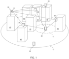
- FIG. 1 is an illustration showing an example of the cellular-method radio communication system using the radio-wave reflecting plate according to the embodiment.
- the radio communication system has a base station 10 installed on a roof of a building 40 such as an architecture, and uses a radio wave with a predetermined frequency band from a transmission antenna 11 of the base station 10 to perform a radio communication with a terminal apparatus (also called "user equipment (UE)" or “mobile station”) 30 located in a cell 12 on the ground or on the sea.
- UE user equipment
- the radio wave in the high frequency band has a short wavelength
- the radio wave is susceptible to blockage by obstacles such as trees and buildings, and there is a concern that a communication cannot be performed.
- the radio wave is easily affected by blockage by the building 40, and a non-line-of sight area out of line-of-sight against the transmission antenna 11 of the base station 10 is generated, so there is a concern that a communication between the base station 10 and the terminal apparatus 30 in the non-line-of-sight area 13 cannot be performed.
- a similar problem may occur not only in the case of communication, but also in the case of radio power supply to the terminal apparatus 30 from a power transmission antenna using radio waves in the high frequency band.
- radio-wave reflecting plates 20 as radio-wave reflecting members are installed on wall surfaces or roofs of the buildings 40. It is noted the radio-wave reflecting member may have a shape other than the plate shape.
- the radio-wave reflecting plate 20 is a reflecting plate in which the reflection direction of radio waves can be controlled, and its installation position is, for example, a place that is line-of-sight against the transmission antenna (transmission point Tx) 11 of the base station 10 and is a position by which one reflection occurs in the path from the transmission antenna (transmission point Tx) 11 to the target reception point Rx in the non-line-of-sight area 13.
- the target reception point Rx may be, for example, a geometric center position of the non-line-of-sight area 13 or a position where the distribution density (predicted density) of the terminal apparatuses 30 in the non-line-of-sight area 13 is high.
- the installation positions of the radio-wave reflecting plates 20 it is necessary to dispose the necessary number of radio-wave reflecting plates 20 in an appropriate place (for example, wall surface of building) so that the radio waves reach the non-line-of-sight area 13 with a predetermined power.
- an appropriate place for example, wall surface of building
- a field survey is conducted to determine the installation positions of the radio-wave reflecting plates, it costs a lot of man-hours and labor costs for the field survey.
- the installation positions of the radio-wave reflecting plates 20 are determined without conducting the expensive field survey.
- FIG. 2 is a functional block diagram showing an example of a main configuration of an information processing apparatus 50 for determining the installation position of the radio-wave reflecting plate 20 according to the embodiment.
- the information processing apparatus 50 may be configured with a single server or plural servers connected to a communication network such as the Internet or a mobile communication network, or may be configured with a cloud system configured with plural computers connected to a communication network.
- the information processing apparatus 50 is configured with, for example, a computer or processor, and can function as the following sections by loading and executing a predetermined program installed in advance or a predetermined program downloaded via a communication network.
- the information processing apparatus 50 is provided with a map-information storage section (map DB) 501, a propagation-path setting section 502, a reception-characteristics estimating section 503 and an installation-position determining section 504.
- the map-information storage section 501 stores map information of the target area including information on the three-dimensional coordinates of obstacles such as the building 40 that obstruct radio the wave propagation in the target area such as the cell 12.
- the propagation-path setting section 502 sets plural radio-wave propagation paths P(1) to P(N) with one reflection between the radio-wave transmission point Tx and the target reception point Rx located in the area out of line-of-sight (non-line-of-sight area) 13 against the transmission antenna 11 of the base station 10 which is the radio-wave transmission point Tx in the target area.
- the reception-characteristics estimating section 503 estimates a reception power as reception characteristics at target reception point Rx for each of the plural radio-wave propagation paths P(1) to P(N).
- the estimated reception characteristics may be a propagation loss from the transmission point Tx of the transmission antenna 11 of the base station 10 to the target reception point Rx.
- the installation-position determining section 504 selects the radio-wave propagation paths P(n) in descending order of the reception power at the target reception point, calculates a total value of the reception powers , and determines the installation positions of the radio-wave reflecting plates 20 as one or more radio-wave reflecting members, based on the results of selecting one or more radio-wave propagation paths by a time when the total value exceeds a predetermined target quality (threshold value).
- the information processing apparatus 50 may be further provided with a communication-traffic estimating section 505 and a reflection-beam determining section 506.
- the communication-traffic estimating section 505 estimates a communication traffic amount due to the terminal apparatus 30 located in the non-line-of-sight area 13, as exemplified below.
- the reflection-beam determining section 506 sets a shape of reflection beam and the number of reflection beams of the radio-wave reflecting plate 20 for which the installation position is determined based on the estimation result of the communication traffic amount, as exemplified below.
- FIG. 3 is a flowchart showing an example of a method for determining the installation positions of the radio-wave reflecting plates 20 according to the embodiment
- FIG. 4 is an illustration showing an example of radio-wave propagation paths P with plural reflections in the method of FIG. 3 .
- the method for determining the installation positions of the radio-wave reflecting plates 20 in FIG. 3 can be implemented, for example, by the information processing apparatus 50 having the configuration in FIG. 2 described above.
- Each of the reflection points 21(1) to 21(4) on radio-wave propagation paths P(1) to P(4) in the figure is a point that is a line-of-sight against the transmission point Tx (antenna 11 of the base station 10) and the target reception point Rx.
- the reflection points 21(1) to 21(4) are set on the wall surfaces of the buildings 40 in the examples of FIG. 3 and FIG. 4 , the reflection points may be set on the roofs of the buildings 40. Furthermore, although the examples in FIG. 3 and FIG. 4 show the case that the number of radio-wave propagation paths P(1) to P(4) with one reflection is four paths, the number of radio-wave propagation paths P may be three paths or less, or may be five paths or more.
- the information processing apparatus 50 sets simulation conditions such as frequency of radio waves, transmission power, position coordinates of the transmission point Tx, the target reception point Rx, and the reflection characteristics parameters of the radio-wave reflecting plate 20, and sets plural radio-wave propagation paths (hereinafter also referred to as "paths") P(1) to P(N) from the transmission point Tx to the target reception point Rx with one of reflection, based on the map information under the simulation conditions (S101).
- N is the set number of the paths.
- the Ray Trace method is a method for estimating the propagation characteristics of radio waves by treating radio waves as straight rays and approximately modeling plural propagation paths that exist between transmission and reception points, as rays composed of direct waves, reflected waves, and diffracted waves of radio waves.
- the information processing apparatus 50 estimates the reception power when the radio wave transmitted from the transmission point Tx is received at the target reception point Rx via each propagation path, and numbers by ranking the paths P(1) to P(N) in descending order of the estimated values of their reception power.
- the paths are referred to as the first path P(1) to the N-th path P(N) in descending order of the estimated values of reception power.
- the information processing apparatus 50 selects paths in descending order of the estimated values of reception power at the target reception point Rx and calculates the total value Pt of reception power, and determines whether or not the total value is greater than a predetermined threshold value (target quality) (S103 to S106). For example, the information processing apparatus 50 first selects the first path P(1) (S103), and calculates the total value Pt of the reception power (S104). When the first path P(1) is selected, the total value Pt of the reception power is equal to the reception power received via the first path P(1).
- a predetermined threshold value target quality
- the information processing apparatus 50 compares the total value Pt with the threshold value (S105), and if the total value Pt is equal to or less than the threshold value (No in S105), additionally selects the next second pass P(2) (S106), calculates the total value of reception power, and compares the total value with the threshold value (S104, S105). These additional selection of paths, calculation of the total value of reception power and comparison of the total value and the threshold value are repeatedly executed until the total value Pt becomes greater than the threshold value.
- the information processing apparatus 50 determines the installation positions and the number of radio-wave reflecting plates 20 corresponding to the paths selected so far (S107). For example, in the example of FIG. 4 , each of the reflection points 21(1) to 21(4) is determined as the installation position of the radio-wave reflecting plate 20, and the number of the radio-wave reflecting plates 20 is determined to be four.
- FIG. 5 is an illustration showing an example of one reflection by the radio-wave reflecting plate 20 installed at the reflection point 21 of the line-of-sight path selected in FIG. 3 and FIG. 4 .
- FIG. 6 is a perspective view showing an example of the configuration of the radio-wave reflecting plate 20 according to the embodiment.
- the radio-wave reflecting plate 20 in FIG. 6 has a configuration in which plural reflecting elements 20a are two-dimensionally disposed in an array.
- Each of the plural reflecting elements 20a has a surface structure called a meta-surface consisting of three layers, for example, a frequency selective plate (FSS: Frequency Selective Surface), a dielectric layer and a bottom plate, in order from the surface.
- FSS Frequency Selective Surface
- ⁇ i, j 2 ⁇ ⁇ pi sin ⁇ out cos ⁇ out ⁇ sin ⁇ in cos ⁇ in + pj sin ⁇ out sin ⁇ out ⁇ sin ⁇ in sin ⁇ in
- ⁇ is wavelength of the radio wave
- each of the ⁇ in and ⁇ out is incidence angle and reflection angle on the y-z plane in the figure
- each of the ⁇ in and ⁇ out is incidence angle and reflection angle on the x-z plane in the figure.
- each of the pi and pj is the pitch of the reflecting elements 20a in the x-direction and y-direction in the figure.
- the shape and reflection angle of the reflection beam of the radio-wave reflecting plate 20 may be determined by, for example, the following method.
- This method is a method of applying a Directionally Constrained Minimization of Power (DCMP) technique and utilizing a method of forming plural beams by controlling the null direction.
- DCMP Directionally Constrained Minimization of Power
- FIG. 7 is a flow chart showing an example of a method for determining the shape and reflection angle of the reflection beam of the radio-wave reflecting plate 20 according to the embodiment.
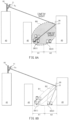
- FIG. 8A is an illustration of searching for the terminal apparatus 30 in the non-line-of-sight area 13 using the broad-shaped reflection beam of the radio-wave reflecting plate 20 according to the embodiment
- FIG. 8B is an illustration showing an example of plural reflection beams formed in the non-line-of-sight area 13 by the radio-wave reflecting plate 20 according to the embodiment.
- the method for determining the shape and reflection angle of the reflection beam of the radio-wave reflecting plate 20 in FIG. 7 , FIG. 8A and FIG. 8B can be implemented, for example, by the communication-traffic estimating section 505 and the reflection-beam determining section 506 of the information processing apparatus 50 having the configuration shown in FIG. 2 described above.
- the information processing apparatus 50 first estimates the traffic amount in the non-line-of-sight area 13 (S201), and then searches for the terminal apparatus 30 (S202). This search can be performed based on the measurement report (MR) reported from the terminal apparatus 30 to the base station 10, for example, in the case of a broad beam having a beam width such that the reflection beam from the radio-wave reflecting plate 20 to the non-line-of-sight area 13 covers the entire non-line-of-sight area 13 (see FIG. 8A ).
- MR measurement report
- the information processing apparatus 50 performs a grouping based on the measurement report from the terminal apparatus 30, and divides the non-line-of-sight area 13 into plural divided areas based on the map information (S203). For example, the non-line-of-sight area 13 is divided into two divided areas A1 and A2 as shown in FIG. 8A .
- the information processing apparatus 50 estimates the reception power of the terminal apparatus 30 in each divided area, and estimates the communication traffic amount in each divided area (S203, S204). For example, the reception power of the first-group terminal apparatuses 30 located in the divided area A1 shown in FIG. 8A is estimated, and the communication traffic amount in the divided area A1 is estimated based on the estimation result of the reception power. Also, the reception power of the second-group terminal apparatuses 30 located in the divided area A2 is estimated, and the communication traffic amount in the divided area A2 is estimated based on the estimation result of the reception power.
- the information processing apparatus 50 determines, for each of the divided areas, a weight of the reflection beam from the radio-wave reflecting plate 20 based on the estimation result of the communication traffic amount (S205). For example, as shown in FIG. 8B , the weight for forming the reflection beam B1 directed from the radio-wave reflecting plate 20 toward the terminal apparatus group in the divided area A1 is determined according to the communication traffic amount in the divided area A1, and the weight for forming the reflection beam B2 directed from the radio-wave reflecting plate 20 toward the terminal apparatus group in the divided area A2 is determined according to the communication traffic amount in the divided area A2.
- the information processing apparatus 50 calculates and determines the shape and the reflection angle of the reflection beam including plural beams directed toward each divided area (S206). For example, as shown in FIG. 8B , by controlling the null direction toward the boundary between the divided areas A1 and A2 based on the weights of the divided areas A1 and A2, the shapes and reflection angles of the reflection beams including the plural beams B1 and B2 respectively directed toward the divided area A1 and A2 are calculated and determined.
- DCMP Directionally Constrained Minimization of Power
- the method for determining the shape and reflection angle of the reflection beam directed from the radio-wave reflecting plate 20 toward the non-line-of-sight area 13 exemplified in FIG. 7 , FIG. 8A and FIG. 8B can also be applied to the radio-wave reflecting plates 20 whose installation positions and number are determined by the method shown in FIG. 9 to FIG. 11B below.
- FIG. 9 is a functional block diagram showing another example of the main configuration of the information processing apparatus 50 that determines the installation position of the radio-wave reflecting plate 20 according to the embodiment.
- the description of the parts common to the above-described information processing apparatus in FIG. 2 is omitted.
- the information processing apparatus 50 is provided with a map-information storage section (map DB) 511, an installation-candidate position searching section 512, an installation-candidate position selecting section 513, and an installation-position determining section 514.
- the map-information storage section 511 stores map information of the target area including information on the three-dimensional coordinates of obstacles such as the buildings 40 that obstruct radio wave propagation in the target area such as the cell 12.
- the installation-candidate position searching section 512 searches for installation candidate positions of plural radio-wave reflecting plates 20 that are line-of sight against the radio-wave transmission point Tx in the target area, based on the map information of the target area.
- the installation-candidate position selecting section 513 selects one or plural installation candidate positions that have a line-of-sight positional relationship between the target reception point Rx located in the non-line-of-sight area 13 against the radio-wave transmission point Tx and the reflection-light candidate point, from among the plural installation candidate positions searched by the installation-candidate position searching section 512.
- the installation-position determining section 514 determines the installation position of the radio-wave reflecting plate 20 based on the selection result of the installation candidate position selected by the installation-candidate position selecting section 513.
- the information processing apparatus 50 may be further provided with a communication-traffic estimating section 516 and a reflection-beam determining section 517.
- the communication-traffic estimating section 516 estimates the communication traffic amount due to the terminal apparatus 30 located in the non-line-of-sight area 13.
- the reflection-beam determining section 517 sets the shape and the number of reflection beams of the radio-wave reflecting plate 20 whose installation position is determined based on the estimation result of the communication traffic amount.
- FIG. 10 is a flow chart showing another example of the method for determining the installation position of the radio-wave reflecting plate 20 according to the embodiment.
- FIG. 11A is an illustration showing an example of search results of the installation candidate positions for the radio-wave reflecting plate 20 in the method of FIG. 10
- FIG. 11B is an illustration showing an example of a narrow selection result of the installation candidate positions of the radio-wave reflecting plate 20 in the method of FIG. 10 .
- the information processing section 50 sets simulation conditions such as frequency of radio waves, transmission power, position coordinates of the transmission point Tx, the target reception point Rx, and reflection characteristics parameters of the radio-wave reflecting plate 20 (S301), and searches for and sets plural installation candidate positions 22 of the radio-wave reflecting plate 20 that are line-of-sight against the transmission point Tx where the transmission antenna 11 of the base station 10 is located, based on the map information under the simulation conditions (S302). For example, as exemplified in FIG. 11A , plural installation candidate positions 22 indicated by white circles in the figure are searched and set on the wall surface of the building 40 that is a line-of-sight against the transmission point Tx.
- the information processing apparatus 50 selects one or plural installation candidate positions 24 that are line-of-sight against the target reception point Rx, from among the plural installation candidate positions 22 that are searched and set as described above (S303). For example, as exemplified in FIG. 11B , plural installation candidate positions 24 indicated by cross-hatched circles and black circles in the figure, which are line-of-sight against the target reception point Rx, are selected among from the plural installation candidate positions 22.
- the plural installation candidate positions 23 indicated by hatched circles in the figure are out of line-of-sight against the target reception point Rx, and are not selected.
- the information processing apparatus 50 narrows down and determines the number and the installation positions of the installation candidate positions 25 of the radio-wave reflecting plate 20 from among the plural installation candidate positions 24 that are selected described above, based on the parameters of the radio-wave reflecting plate 20 (for example, incident angle, reflection angle, half-value width of the reflection beam) (S304).
- the installation candidate position 25 indicated by the black circle in the figure, which is one of the plural installation candidate positions 24, is determined as the installation position of the radio-wave reflecting plate 20, and it is determined that the number of radio-wave reflecting plates 20 is one.
- the radio-wave reflecting plate 20 it is possible to determine the installation position of the radio-wave reflecting plate 20 without conducting an expensive field survey, so that the radio waves with a predetermined power reach the target reception point Rx located in the non-line-of-sight area 13 from the transmission point Tx (for example, transmission antenna 11 of the base station 10) of radio waves with a high frequency band such as quasi-millimeter waves, millimeter waves, and terahertz waves.
- a high frequency band such as quasi-millimeter waves, millimeter waves, and terahertz waves.
- process steps and configuration elements of the information processing apparatus, radio communication system, and mobile communication system described in the present description can be implemented with various means.
- these process steps and configuration elements may be implemented with hardware, firmware, software, or a combination thereof.
- means such as processing units or the like used for establishing the foregoing steps and configuration elements in entities may be implemented in one or more of an application-specific IC (ASIC), a digital signal processor (DSP), a digital signal processing apparatus (DSPD), a programmable logic device (PLD), a field programmable gate array (FPGA), a processor, a controller, a microcontroller, a microprocessor, an electronic device, other electronic unit, computer, or a combination thereof, which are designed so as to perform a function described in the present specification.
- ASIC application-specific IC
- DSP digital signal processor
- DSPD digital signal processing apparatus
- PLD programmable logic device
- FPGA field programmable gate array
- processor a controller, a microcontroller, a microprocessor, an electronic device, other electronic unit, computer, or a combination thereof, which are designed so as to perform a function described in the present specification.
- means such as processing units or the like used for establishing the foregoing configuration elements may be implemented with a program (for example, code such as procedure, function, module, instruction, etc.) for performing a function described in the present specification.
- a program for example, code such as procedure, function, module, instruction, etc.
- any computer/processor readable medium of materializing the code of firmware and/or software may be used for implementation of means such as processing units and so on for establishing the foregoing steps and configuration elements described in the present specification.
- the firmware and/or software code may be stored in a memory and executed by a computer or processor.
- the memory may be implemented within the computer or processor, or outside the processor.
- firmware and/or software code may be stored in, for example, a medium capable being read by a computer or processor, such as a random-access memory (RAM), a read-only memory (ROM), a non-volatility random-access memory (NVRAM), a programmable read-only memory (PROM), an electrically erasable PROM (EEPROM), a FLASH memory, a floppy (registered trademark) disk, a compact disk (CD), a digital versatile disk (DVD), a magnetic or optical data storage unit, or the like.
- RAM random-access memory
- ROM read-only memory
- NVRAM non-volatility random-access memory
- PROM programmable read-only memory
- EEPROM electrically erasable PROM
- FLASH memory a FLASH memory
- floppy (registered trademark) disk a compact disk (CD), a digital versatile disk (DVD)
- CD compact disk
- DVD digital versatile disk
- magnetic or optical data storage unit or the like.
- the medium may be a non-transitory recording medium.
- the code of the program may be executable by being read by a computer, a processor, or another device or an apparatus machine, and the format is not limited to a specific format.
- the code of the program may be any of a source code, an object code, and a binary code, and may be a mixture of two or more of those codes.
Landscapes
- Engineering & Computer Science (AREA)
- Computer Networks & Wireless Communication (AREA)
- Signal Processing (AREA)
- Quality & Reliability (AREA)
- Physics & Mathematics (AREA)
- Electromagnetism (AREA)
- Mobile Radio Communication Systems (AREA)
Abstract
Description
- The present invention relates to an information processing apparatus, method and program for determining an installation position of a radio-wave reflecting member such as a radio-wave reflecting plate which reflects a radio wave in a high frequency band such as a millimeter wave band.
- In recent years, an introduction of a next-generation mobile communication system such as the 5th generation is expected to solve a problem of communication traffic caused by an increase in the number of terminal apparatuses in the mobile communication. In particular, the use of radio waves in high-frequency bands such as quasi-millimeter waves, millimeter waves, and terahertz waves, which are characterized by high speed and large capacity, has been attracting attention. However, since such radio waves in the high-frequency bands have short wavelengths, there are likely to be areas out of line-of-sight (also called "dead area" or "communication impossible area") where a communication is not possible due to a shielding by obstacles such as trees and buildings. Further, in case of using the above-mentioned radio waves in the high frequency bands for a radio power supply, the area out of line-of-sight are likely to occur where the radio power supply is not possible due to the shielding by obstacles such as buildings.
- In order to eliminate the foregoing areas where the communication of high-frequency band and the radio power supply cannot be performed, a use of a radio-wave reflecting plate capable of controlling a reflection direction of radio wave (see, for example, Patent Literature 1) is expected.
- Patent Literature 1:
Japanese Unexamined Patent Publication No. 2010-226695 - In case of installing the radio-wave reflecting plate, the necessary number of radio-wave reflecting plate needs to be disposed in appropriate places (for example, wall surfaces of buildings) so that the radio waves reach an area out of line-of-sight against a transmission point such as a base station that transmits the radio waves with a predetermined power. However, there is a problem that it is necessary to conduct an on-site survey to determine the installation position of the radio-wave reflecting plate in the current situation, and a large amount of man-hours and labor costs are required.
- An information processing apparatus according to a first aspect of the present invention is an information processing apparatus for performing a process of determining an installation position of a radio-wave reflecting member. This information processing apparatus comprises a propagation-path setting section for setting plural radio-wave propagation paths each with one reflection between a radio-wave transmission point in a target area and a target reception point located in an area out of line-of-sight against the radio-wave transmission point, based on map information of the target area, a reception-characteristics estimating section for estimating reception characteristics at the target reception point for each of the plural radio-wave propagation paths, and an installation-position determining section for calculating a total value of the reception characteristics by selecting the radio-wave propagation paths in descending order of reception characteristics at the target reception point, and for determining an installation position of a radio-wave reflecting member based on a selection result of one or more radio-wave propagation paths selected by a time when the total value becomes higher than a predetermined target quality.
- A method according to a first aspect of the present invention is a method for determining an installation position of a radio-wave reflecting member. This method includes setting plural radio-wave propagation paths each with one reflection between a radio-wave transmission point in a target area and a target reception point located in an area out of line-of-sight against the radio-wave transmission point, based on map information of the target area, estimating reception characteristics at the target reception point for each of the plural radio-wave propagation paths, and calculating a total value of the reception characteristics by selecting the radio-wave propagation paths in descending order of reception characteristics at the target reception point, and determining an installation position of a radio-wave reflecting member based on a selection result of one or more radio-wave propagation paths selected by a time when the total value becomes higher than a predetermined target quality.
- A program according to a first aspect of the present invention is a program executed by a computer or processor provided in an apparatus for determining an installation position of a radio-wave reflecting member, which includes a program code for setting plural radio-wave propagation paths each with one reflection between a radio-wave transmission point in a target area and a target reception point located in an area out of line-of-sight against the radio-wave transmission point, based on map information of the target area, a program code for estimating reception characteristics at the target reception point for each of the plural radio-wave propagation paths, and a program code for calculating a total value of the reception characteristics by selecting the radio-wave propagation paths in descending order of reception characteristics at the target reception point, and determining an installation position of a radio-wave reflecting member based on a selection result of one or more radio-wave propagation paths selected by a time when the total value becomes higher than a predetermined target quality.
- In each of the foregoing information processing apparatus, method and program according to the first aspect, the reception characteristics may be a reception power at the target reception point or a propagation loss from the transmission point to the target reception point.
- An information processing apparatus according to a second aspect of the present invention is an information processing apparatus that performs processing for determining an installation position of a radio-wave reflecting member. This information processing apparatus comprises an installation-candidate position searching section for searching for plural installation candidate positions of the radio-wave reflecting member, which are line-of-sight against a radio-wave transmission point in a target area, based on map information of the target area, an installation-candidate position selecting section for selecting one or more installation candidate positions from among the plural installation candidate positions, which have a line-of-sight positional relationship between a target reception point located in an area out of line-of-sight against the radio-wave transmission point and a reflection-light candidate point, and an installation position determining section for determining an installation position of the radio-wave reflecting member based on the selection result of the installation candidate positions.
- A method according to a second aspect of the present invention is a method for determining an installation position of a radio-wave reflecting member. This method includes searching for plural installation candidate positions of the radio-wave reflecting member, which are line-of-sight against a radio-wave transmission point in a target area, based on map information of the target area, selecting one or more installation candidate positions from among the plural installation candidate positions, which have a line-of-sight positional relationship between a target reception point located in an area out of line-of-sight against the radio-wave transmission point and a reflection-light candidate point, and determining an installation position of the radio-wave reflecting member based on the selection result of the installation candidate positions.
- A program according to a second aspect of the present invention is a program executed by a computer or processor provided in an apparatus for determining an installation position of a radio-wave reflecting member. This program includes a program code for searching for plural installation candidate positions of the plural radio-wave reflecting member, which are line-of-sight against a radio-wave transmission point in a target area, based on map information of the target area, a program code for selecting one or more installation candidate positions from among the plural installation candidate positions, the one or more installation candidate positions, which have a line-of-sight positional relationship between a target reception point located in an area out of line-of-sight against the radio-wave transmission point and a reflection-light candidate point, and a program code for determining an installation position of the radio-wave reflecting member based on the selection result of the installation candidate positions.
- In each of the foregoing information processing apparatus, method and program according to the second aspect, the installation-position determining section may narrow down and determine the installation position of the radio-wave reflecting member based on a reflection characteristics parameter of the radio-wave reflecting member, when plural installation candidate positions are selected.
- In each of the foregoing information processing apparatus, method and program according to the first aspect and the second aspect, the shape and the number of reflection beams of the radio-wave reflecting member may be determined based on a communication traffic amount by a terminal apparatus located in the area out of line-of-sigh.
- According to the present invention, it is possible to determine an installation position of a radio-wave reflecting member without conducting an expensive field survey, so that radio waves with a predetermined power reach a target reception point located in an area out of line-of-sight area, from a transmission point of radio wave with a high frequency band.
-
- [
FIG. 1] FIG. 1 is an illustration showing an example of a cellular radio communication system using a radio-wave reflecting plate according to an embodiment. - [
FIG. 2] FIG. 2 is a functional block diagram showing an example of a main configuration of an information processing apparatus for determining an installation position of a radio-wave reflecting plate according to an embodiment. - [
FIG. 3] FIG. 3 is a flow chart showing an example of a method for determining an installation position of a radio-wave reflecting plate according to an embodiment. - [
FIG. 4] FIG. 4 is an illustration showing an example of radio-wave propagation paths with plural reflections in the method ofFIG. 3 . - [
FIG. 5] FIG. 5 is an illustration showing an example of one reflection by a radio-wave reflecting plate. - [
FIG. 6] FIG. 6 is a perspective view showing an example of a configuration of a radio-wave reflecting plate according to an embodiment. - [
FIG. 7] FIG. 7 is a flow chart showing an example of a method for determining a shape and reflection angle of a reflection beam of a radio-wave reflecting plate according to an embodiment. - [
FIG. 8A] FIG. 8A is an illustration of searching for a terminal apparatus in an area out of line-of-sight using a broad-shaped reflection beam of a radio-wave reflecting plate according to an embodiment. - [
FIG. 8B] FIG. 8B is a flowchart showing an example of plural reflection beams formed in an area out of line-of-sight by a radio-wave reflecting plate according to an embodiment. - [
FIG. 9] FIG. 9 is a functional block diagram showing another example of a main configuration of an information processing apparatus for determining an installation position of a radio-wave reflecting plate according to an embodiment. - [
FIG. 10] FIG. 10 is a flow chart showing another example of a method for determining an installation position of a radio-wave reflecting plate according to an embodiment. - [
FIG. 11A] FIG. 11A is an illustration showing an example of a search result of installation candidate positions of radio-wave reflecting plates according to an embodiment. - [
FIG. 11B] FIG. 11B is an illustration showing an example of a narrow-down selection result of installation candidate positions of radio-wave reflecting plates according to an embodiment. - Hereinafter, embodiments of the present invention are described with reference to the drawings.
- An information processing apparatus according to the embodiment described herein can determine an installation position of a radio-wave reflecting plate without conducting an expensive field survey, in a cellular-method radio communication system for improving a communication quality of an area out of line-of-sight, by reflecting radio waves with high frequency band (for example, quasi-millimeter wave, millimeter wave, terahertz wave) transmitted from a transmission antenna by one or more radio-wave reflecting plates and reaching them to an area that is out of line-of-sight (hereinafter referred to as "non-line-of-sight area") against the transmission antenna (radio-wave transmission point) of a base station (for example, eNodeB in the LTE or gNodeB in the next generation such as the 5G) in a target area such as an urban area with many obstacles such as buildings.
-
FIG. 1 is an illustration showing an example of the cellular-method radio communication system using the radio-wave reflecting plate according to the embodiment. InFIG. 1 , the radio communication system has abase station 10 installed on a roof of abuilding 40 such as an architecture, and uses a radio wave with a predetermined frequency band from atransmission antenna 11 of thebase station 10 to perform a radio communication with a terminal apparatus (also called "user equipment (UE)" or "mobile station") 30 located in acell 12 on the ground or on the sea. In this radio communication system, an introduction of a mobile communication system of the next-generation such as the 5th generation is expected to solve a problem of communication traffic caused by an increase in the number ofterminal apparatuses 30. In particular, the use of high frequency band of quasi-millimeter waves (10 GHz to 30 GHz), millimeter waves (30 GHz to 300 GHz), terahertz waves (300 GHz to 3 THz), or the like, which has features such as high speed and large capacity, is attracting attention. - However, since the radio wave in the high frequency band has a short wavelength, the radio wave is susceptible to blockage by obstacles such as trees and buildings, and there is a concern that a communication cannot be performed. Especially in an urban area, there are
many buildings 40 as shown inFIG. 1 , the radio wave is easily affected by blockage by thebuilding 40, and a non-line-of sight area out of line-of-sight against thetransmission antenna 11 of thebase station 10 is generated, so there is a concern that a communication between thebase station 10 and theterminal apparatus 30 in the non-line-of-sight area 13 cannot be performed. A similar problem may occur not only in the case of communication, but also in the case of radio power supply to theterminal apparatus 30 from a power transmission antenna using radio waves in the high frequency band. - In the present embodiment, as shown in
FIG. 1 , in order to improve the communication quality of the high frequency band in the non-line-of-sight area 13, radio-wave reflecting plates 20 as radio-wave reflecting members are installed on wall surfaces or roofs of thebuildings 40. It is noted the radio-wave reflecting member may have a shape other than the plate shape. - The radio-
wave reflecting plate 20 is a reflecting plate in which the reflection direction of radio waves can be controlled, and its installation position is, for example, a place that is line-of-sight against the transmission antenna (transmission point Tx) 11 of thebase station 10 and is a position by which one reflection occurs in the path from the transmission antenna (transmission point Tx) 11 to the target reception point Rx in the non-line-of-sight area 13. - The target reception point Rx may be, for example, a geometric center position of the non-line-of-
sight area 13 or a position where the distribution density (predicted density) of theterminal apparatuses 30 in the non-line-of-sight area 13 is high. - As for the installation positions of the radio-
wave reflecting plates 20, it is necessary to dispose the necessary number of radio-wave reflecting plates 20 in an appropriate place (for example, wall surface of building) so that the radio waves reach the non-line-of-sight area 13 with a predetermined power. However, if a field survey is conducted to determine the installation positions of the radio-wave reflecting plates, it costs a lot of man-hours and labor costs for the field survey. - In the present embodiment, as described hereinafter, the installation positions of the radio-
wave reflecting plates 20 are determined without conducting the expensive field survey. -
FIG. 2 is a functional block diagram showing an example of a main configuration of aninformation processing apparatus 50 for determining the installation position of the radio-wave reflecting plate 20 according to the embodiment. Theinformation processing apparatus 50 may be configured with a single server or plural servers connected to a communication network such as the Internet or a mobile communication network, or may be configured with a cloud system configured with plural computers connected to a communication network. Theinformation processing apparatus 50 is configured with, for example, a computer or processor, and can function as the following sections by loading and executing a predetermined program installed in advance or a predetermined program downloaded via a communication network. - In
FIG. 2 , theinformation processing apparatus 50 is provided with a map-information storage section (map DB) 501, a propagation-path setting section 502, a reception-characteristics estimating section 503 and an installation-position determining section 504. The map-information storage section 501 stores map information of the target area including information on the three-dimensional coordinates of obstacles such as thebuilding 40 that obstruct radio the wave propagation in the target area such as thecell 12. - Based on the map information of the target area, the propagation-
path setting section 502 sets plural radio-wave propagation paths P(1) to P(N) with one reflection between the radio-wave transmission point Tx and the target reception point Rx located in the area out of line-of-sight (non-line-of-sight area) 13 against thetransmission antenna 11 of thebase station 10 which is the radio-wave transmission point Tx in the target area. - The reception-
characteristics estimating section 503 estimates a reception power as reception characteristics at target reception point Rx for each of the plural radio-wave propagation paths P(1) to P(N). The estimated reception characteristics may be a propagation loss from the transmission point Tx of thetransmission antenna 11 of thebase station 10 to the target reception point Rx. - The installation-
position determining section 504 selects the radio-wave propagation paths P(n) in descending order of the reception power at the target reception point, calculates a total value of the reception powers , and determines the installation positions of the radio-wave reflecting plates 20 as one or more radio-wave reflecting members, based on the results of selecting one or more radio-wave propagation paths by a time when the total value exceeds a predetermined target quality (threshold value). - In
FIG. 2 , theinformation processing apparatus 50 may be further provided with a communication-traffic estimating section 505 and a reflection-beam determining section 506. The communication-traffic estimating section 505 estimates a communication traffic amount due to theterminal apparatus 30 located in the non-line-of-sight area 13, as exemplified below. The reflection-beam determining section 506 sets a shape of reflection beam and the number of reflection beams of the radio-wave reflecting plate 20 for which the installation position is determined based on the estimation result of the communication traffic amount, as exemplified below. -
FIG. 3 is a flowchart showing an example of a method for determining the installation positions of the radio-wave reflecting plates 20 according to the embodiment, andFIG. 4 is an illustration showing an example of radio-wave propagation paths P with plural reflections in the method ofFIG. 3 . The method for determining the installation positions of the radio-wave reflecting plates 20 inFIG. 3 can be implemented, for example, by theinformation processing apparatus 50 having the configuration inFIG. 2 described above. Each of the reflection points 21(1) to 21(4) on radio-wave propagation paths P(1) to P(4) in the figure is a point that is a line-of-sight against the transmission point Tx (antenna 11 of the base station 10) and the target reception point Rx. - It is noted that, although the reflection points 21(1) to 21(4) are set on the wall surfaces of the
buildings 40 in the examples ofFIG. 3 andFIG. 4 , the reflection points may be set on the roofs of thebuildings 40. Furthermore, although the examples inFIG. 3 andFIG. 4 show the case that the number of radio-wave propagation paths P(1) to P(4) with one reflection is four paths, the number of radio-wave propagation paths P may be three paths or less, or may be five paths or more. - In
FIG. 3 , theinformation processing apparatus 50 sets simulation conditions such as frequency of radio waves, transmission power, position coordinates of the transmission point Tx, the target reception point Rx, and the reflection characteristics parameters of the radio-wave reflecting plate 20, and sets plural radio-wave propagation paths (hereinafter also referred to as "paths") P(1) to P(N) from the transmission point Tx to the target reception point Rx with one of reflection, based on the map information under the simulation conditions (S101). Herein, N is the set number of the paths. - For path setting, for example, the Ray Trace method based on the geometric optics theory for radio-wave propagation analysis can be used. The Ray Trace method is a method for estimating the propagation characteristics of radio waves by treating radio waves as straight rays and approximately modeling plural propagation paths that exist between transmission and reception points, as rays composed of direct waves, reflected waves, and diffracted waves of radio waves.
- Next, the
information processing apparatus 50 estimates the reception power when the radio wave transmitted from the transmission point Tx is received at the target reception point Rx via each propagation path, and numbers by ranking the paths P(1) to P(N) in descending order of the estimated values of their reception power. Hereinafter, the paths are referred to as the first path P(1) to the N-th path P(N) in descending order of the estimated values of reception power. - Next, the
information processing apparatus 50 selects paths in descending order of the estimated values of reception power at the target reception point Rx and calculates the total value Pt of reception power, and determines whether or not the total value is greater than a predetermined threshold value (target quality) (S103 to S106). For example, theinformation processing apparatus 50 first selects the first path P(1) (S103), and calculates the total value Pt of the reception power (S104). When the first path P(1) is selected, the total value Pt of the reception power is equal to the reception power received via the first path P(1). Next, theinformation processing apparatus 50 compares the total value Pt with the threshold value (S105), and if the total value Pt is equal to or less than the threshold value (No in S105), additionally selects the next second pass P(2) (S106), calculates the total value of reception power, and compares the total value with the threshold value (S104, S105). These additional selection of paths, calculation of the total value of reception power and comparison of the total value and the threshold value are repeatedly executed until the total value Pt becomes greater than the threshold value. - When the total value Pt becomes greater than the threshold value (YES in S105), the
information processing apparatus 50 determines the installation positions and the number of radio-wave reflecting plates 20 corresponding to the paths selected so far (S107). For example, in the example ofFIG. 4 , each of the reflection points 21(1) to 21(4) is determined as the installation position of the radio-wave reflecting plate 20, and the number of the radio-wave reflecting plates 20 is determined to be four. -
FIG. 5 is an illustration showing an example of one reflection by the radio-wave reflecting plate 20 installed at thereflection point 21 of the line-of-sight path selected inFIG. 3 andFIG. 4 . As shown inFIG. 5 , in case that the radio-wave reflecting plate 20 is installed along the wall surface of thebuilding 40, reflection of radio waves is not always regular reflection (incidence angle θin = reflection angle θout). Therefore, in the present embodiment, the radio-wave reflecting plate 20 is used, in which the direction of the reflection beam can be arbitrarily set. -
FIG. 6 is a perspective view showing an example of the configuration of the radio-wave reflecting plate 20 according to the embodiment. The radio-wave reflecting plate 20 inFIG. 6 has a configuration in which plural reflectingelements 20a are two-dimensionally disposed in an array. Each of theplural reflecting elements 20a has a surface structure called a meta-surface consisting of three layers, for example, a frequency selective plate (FSS: Frequency Selective Surface), a dielectric layer and a bottom plate, in order from the surface. Herein, by setting the reflection phase difference δi, j of the reflected wave with respect to the incident wave for theelement 20a of the i-th in x-direction and the j-th in y-direction in the figure based on the following equation (1), a radio wave incident on the radio-wave reflecting plate 20 at an incident angle (θin, ϕin) can be reflected at an arbitrary reflection angle (θout, ϕout).
- In the equation (1), λ is wavelength of the radio wave, each of the θin and θout is incidence angle and reflection angle on the y-z plane in the figure, and each of the ϕin and ϕout is incidence angle and reflection angle on the x-z plane in the figure. In the equation (1), each of the pi and pj is the pitch of the reflecting
elements 20a in the x-direction and y-direction in the figure. - The shape and reflection angle of the reflection beam of the radio-
wave reflecting plate 20 may be determined by, for example, the following method. This method is a method of applying a Directionally Constrained Minimization of Power (DCMP) technique and utilizing a method of forming plural beams by controlling the null direction. -
FIG. 7 is a flow chart showing an example of a method for determining the shape and reflection angle of the reflection beam of the radio-wave reflecting plate 20 according to the embodiment.FIG. 8A is an illustration of searching for theterminal apparatus 30 in the non-line-of-sight area 13 using the broad-shaped reflection beam of the radio-wave reflecting plate 20 according to the embodiment, andFIG. 8B is an illustration showing an example of plural reflection beams formed in the non-line-of-sight area 13 by the radio-wave reflecting plate 20 according to the embodiment. The method for determining the shape and reflection angle of the reflection beam of the radio-wave reflecting plate 20 inFIG. 7 ,FIG. 8A and FIG. 8B can be implemented, for example, by the communication-traffic estimating section 505 and the reflection-beam determining section 506 of theinformation processing apparatus 50 having the configuration shown inFIG. 2 described above. - In
FIG. 7 , theinformation processing apparatus 50 first estimates the traffic amount in the non-line-of-sight area 13 (S201), and then searches for the terminal apparatus 30 (S202). This search can be performed based on the measurement report (MR) reported from theterminal apparatus 30 to thebase station 10, for example, in the case of a broad beam having a beam width such that the reflection beam from the radio-wave reflecting plate 20 to the non-line-of-sight area 13 covers the entire non-line-of-sight area 13 (seeFIG. 8A ). - Next, the
information processing apparatus 50 performs a grouping based on the measurement report from theterminal apparatus 30, and divides the non-line-of-sight area 13 into plural divided areas based on the map information (S203). For example, the non-line-of-sight area 13 is divided into two divided areas A1 and A2 as shown inFIG. 8A . - Next, the
information processing apparatus 50 estimates the reception power of theterminal apparatus 30 in each divided area, and estimates the communication traffic amount in each divided area (S203, S204). For example, the reception power of the first-group terminal apparatuses 30 located in the divided area A1 shown inFIG. 8A is estimated, and the communication traffic amount in the divided area A1 is estimated based on the estimation result of the reception power. Also, the reception power of the second-group terminal apparatuses 30 located in the divided area A2 is estimated, and the communication traffic amount in the divided area A2 is estimated based on the estimation result of the reception power. - Next, the
information processing apparatus 50 determines, for each of the divided areas, a weight of the reflection beam from the radio-wave reflecting plate 20 based on the estimation result of the communication traffic amount (S205). For example, as shown inFIG. 8B , the weight for forming the reflection beam B1 directed from the radio-wave reflecting plate 20 toward the terminal apparatus group in the divided area A1 is determined according to the communication traffic amount in the divided area A1, and the weight for forming the reflection beam B2 directed from the radio-wave reflecting plate 20 toward the terminal apparatus group in the divided area A2 is determined according to the communication traffic amount in the divided area A2. - Next, by controlling the null direction toward the boundary of the divided areas by the method of Directionally Constrained Minimization of Power (DCMP) described above based on the weight of each divided area, the
information processing apparatus 50 calculates and determines the shape and the reflection angle of the reflection beam including plural beams directed toward each divided area (S206). For example, as shown inFIG. 8B , by controlling the null direction toward the boundary between the divided areas A1 and A2 based on the weights of the divided areas A1 and A2, the shapes and reflection angles of the reflection beams including the plural beams B1 and B2 respectively directed toward the divided area A1 and A2 are calculated and determined. - As shown in
FIG. 7 ,FIG. 8A and FIG. 8B , by determining the shape and reflection angle of the reflection beam directed from the radio-wave reflecting plate 20 toward the non-line-of-sight area 13 according to the communication traffic amount distributed in the non-line-of-sight area 13, it is possible to prevent a deterioration of communication quality over the entire non-line-of-sight area 13. - The method for determining the shape and reflection angle of the reflection beam directed from the radio-
wave reflecting plate 20 toward the non-line-of-sight area 13 exemplified inFIG. 7 ,FIG. 8A and FIG. 8B can also be applied to the radio-wave reflecting plates 20 whose installation positions and number are determined by the method shown inFIG. 9 to FIG. 11B below. -
FIG. 9 is a functional block diagram showing another example of the main configuration of theinformation processing apparatus 50 that determines the installation position of the radio-wave reflecting plate 20 according to the embodiment. InFIG. 9 , the description of the parts common to the above-described information processing apparatus inFIG. 2 is omitted. - In
FIG. 9 , theinformation processing apparatus 50 is provided with a map-information storage section (map DB) 511, an installation-candidateposition searching section 512, an installation-candidateposition selecting section 513, and an installation-position determining section 514. The map-information storage section 511 stores map information of the target area including information on the three-dimensional coordinates of obstacles such as thebuildings 40 that obstruct radio wave propagation in the target area such as thecell 12. - The installation-candidate
position searching section 512 searches for installation candidate positions of plural radio-wave reflecting plates 20 that are line-of sight against the radio-wave transmission point Tx in the target area, based on the map information of the target area. - The installation-candidate
position selecting section 513 selects one or plural installation candidate positions that have a line-of-sight positional relationship between the target reception point Rx located in the non-line-of-sight area 13 against the radio-wave transmission point Tx and the reflection-light candidate point, from among the plural installation candidate positions searched by the installation-candidateposition searching section 512. - The installation-
position determining section 514 determines the installation position of the radio-wave reflecting plate 20 based on the selection result of the installation candidate position selected by the installation-candidateposition selecting section 513. - In
FIG. 9 , theinformation processing apparatus 50 may be further provided with a communication-traffic estimating section 516 and a reflection-beam determining section 517. As exemplified inFIG. 7 ,FIG. 8A and FIG. 8B described above, the communication-traffic estimating section 516 estimates the communication traffic amount due to theterminal apparatus 30 located in the non-line-of-sight area 13. As exemplified inFIG. 7 ,FIG. 8A and FIG. 8B described above, the reflection-beam determining section 517 sets the shape and the number of reflection beams of the radio-wave reflecting plate 20 whose installation position is determined based on the estimation result of the communication traffic amount. -
FIG. 10 is a flow chart showing another example of the method for determining the installation position of the radio-wave reflecting plate 20 according to the embodiment.FIG. 11A is an illustration showing an example of search results of the installation candidate positions for the radio-wave reflecting plate 20 in the method ofFIG. 10 , andFIG. 11B is an illustration showing an example of a narrow selection result of the installation candidate positions of the radio-wave reflecting plate 20 in the method ofFIG. 10 . - In
FIG. 10 , theinformation processing section 50 sets simulation conditions such as frequency of radio waves, transmission power, position coordinates of the transmission point Tx, the target reception point Rx, and reflection characteristics parameters of the radio-wave reflecting plate 20 (S301), and searches for and sets plural installation candidate positions 22 of the radio-wave reflecting plate 20 that are line-of-sight against the transmission point Tx where thetransmission antenna 11 of thebase station 10 is located, based on the map information under the simulation conditions (S302). For example, as exemplified inFIG. 11A , plural installation candidate positions 22 indicated by white circles in the figure are searched and set on the wall surface of thebuilding 40 that is a line-of-sight against the transmission point Tx. - Next, the
information processing apparatus 50 selects one or plural installation candidate positions 24 that are line-of-sight against the target reception point Rx, from among the plural installation candidate positions 22 that are searched and set as described above (S303). For example, as exemplified inFIG. 11B , plural installation candidate positions 24 indicated by cross-hatched circles and black circles in the figure, which are line-of-sight against the target reception point Rx, are selected among from the plural installation candidate positions 22. The plural installation candidate positions 23 indicated by hatched circles in the figure are out of line-of-sight against the target reception point Rx, and are not selected. - Next, the
information processing apparatus 50 narrows down and determines the number and the installation positions of the installation candidate positions 25 of the radio-wave reflecting plate 20 from among the plural installation candidate positions 24 that are selected described above, based on the parameters of the radio-wave reflecting plate 20 (for example, incident angle, reflection angle, half-value width of the reflection beam) (S304). For example, as exemplified inFIG. 11B , theinstallation candidate position 25 indicated by the black circle in the figure, which is one of the plural installation candidate positions 24, is determined as the installation position of the radio-wave reflecting plate 20, and it is determined that the number of radio-wave reflecting plates 20 is one. - As described above, in the present embodiment, it is possible to determine the installation position of the radio-
wave reflecting plate 20 without conducting an expensive field survey, so that the radio waves with a predetermined power reach the target reception point Rx located in the non-line-of-sight area 13 from the transmission point Tx (for example,transmission antenna 11 of the base station 10) of radio waves with a high frequency band such as quasi-millimeter waves, millimeter waves, and terahertz waves. - It is noted that, the process steps and configuration elements of the information processing apparatus, radio communication system, and mobile communication system described in the present description can be implemented with various means. For example, these process steps and configuration elements may be implemented with hardware, firmware, software, or a combination thereof.
- With respect to hardware implementation, means such as processing units or the like used for establishing the foregoing steps and configuration elements in entities (for example, various kinds of radio communication apparatuses, Node B, terminal, hard disk drive apparatus, or optical disk drive apparatus) may be implemented in one or more of an application-specific IC (ASIC), a digital signal processor (DSP), a digital signal processing apparatus (DSPD), a programmable logic device (PLD), a field programmable gate array (FPGA), a processor, a controller, a microcontroller, a microprocessor, an electronic device, other electronic unit, computer, or a combination thereof, which are designed so as to perform a function described in the present specification.
- With respect to the firmware and/or software implementation, means such as processing units or the like used for establishing the foregoing configuration elements may be implemented with a program (for example, code such as procedure, function, module, instruction, etc.) for performing a function described in the present specification. In general, any computer/processor readable medium of materializing the code of firmware and/or software may be used for implementation of means such as processing units and so on for establishing the foregoing steps and configuration elements described in the present specification. For example, in a control apparatus, the firmware and/or software code may be stored in a memory and executed by a computer or processor. The memory may be implemented within the computer or processor, or outside the processor. Further, the firmware and/or software code may be stored in, for example, a medium capable being read by a computer or processor, such as a random-access memory (RAM), a read-only memory (ROM), a non-volatility random-access memory (NVRAM), a programmable read-only memory (PROM), an electrically erasable PROM (EEPROM), a FLASH memory, a floppy (registered trademark) disk, a compact disk (CD), a digital versatile disk (DVD), a magnetic or optical data storage unit, or the like. The code may be executed by one or more of computers and processors, and a certain aspect of functionalities described in the present specification may by executed by a computer or processor.
- The medium may be a non-transitory recording medium. Further, the code of the program may be executable by being read by a computer, a processor, or another device or an apparatus machine, and the format is not limited to a specific format. For example, the code of the program may be any of a source code, an object code, and a binary code, and may be a mixture of two or more of those codes.
- The description of embodiments disclosed in the present specification is provided so that the present disclosures can be produced or used by those skilled in the art. Various modifications of the present disclosures are readily apparent to those skilled in the art and general principles defined in the present specification can be applied to other variations without departing from the spirit and scope of the present disclosures. Therefore, the present disclosures should not be limited to examples and designs described in the present specification and should be recognized to be in the broadest scope corresponding to principles and novel features disclosed in the present specification.
-
- 10: base station
- 11: transmission antenna
- 12: cell
- 13: non-line-of-sight area
- 20: radio-wave reflecting plate
- 20a: reflecting element
- 21: reflecting point
- 22 to 24: installation candidate position
- 25: installation position
- 30: terminal apparatus
- 40: building
- 50: information processing apparatus
- 501: map-information storage section
- 502: propagation-path setting section
- 503: reception-characteristics estimating section
- 504: installation-position determining section
- 505: communication-traffic estimating section
- 506: reflection-beam determining section
- 511: map-information storage section
- 512: installation-candidate position searching section
- 513: installation-candidate position selecting section
- 514: installation-position determining section
- 516: communication-traffic estimating section
- 517: reflection-beam determining section
Claims (9)
- An information processing apparatus for performing a process of determining an installation position of a radio-wave reflecting member, comprising:a propagation-path setting section for setting plural radio-wave propagation paths each with one reflection between a radio-wave transmission point in a target area and a target reception point located in an area out of line-of-sight against the radio-wave transmission point, based on map information of the target area;a reception-characteristics estimating section for estimating reception characteristics at the target reception point for each of the plural radio-wave propagation paths; andan installation-position determining section for calculating a total value of the reception characteristics by selecting the radio-wave propagation paths in descending order of reception characteristics at the target reception point, and for determining an installation position of a radio-wave reflecting member based on a selection result of one or more radio-wave propagation paths selected by a time when the total value becomes higher than a predetermined target quality.
- The information processing apparatus according to claim 1,
wherein the reception characteristics are a reception power at the target reception point or a propagation loss from the transmission point to the target reception point. - An information processing apparatus for performing processing to determine an installation position of a radio-wave reflecting member, comprising:an installation-candidate position searching section for searching for plural installation candidate positions of the radio-wave reflecting member, the installation candidate positions being line-of-sight against a radio-wave transmission point in a target area, based on map information of the target area;an installation-candidate position selecting section for selecting one or more installation candidate positions from among the plural installation candidate positions, the one or more installation candidate positions having a line-of-sight positional relationship between a target reception point located in an area out of line-of-sight against the radio-wave transmission point and a reflection-light candidate point; andan installation position determining section for determining an installation position of the radio-wave reflecting member based on the selection result of the installation candidate positions.
- The information processing apparatus according to claim 3,
wherein the installation-position determining section narrows down and determines the installation position of the radio-wave reflecting member based on a reflection characteristics parameter of the radio-wave reflecting member, when plural installation candidate positions are selected. - The information processing apparatus according to any one of claims 1 to 4, comprising a reflection-beam determining section for determining a shape and the number of reflection beams of the radio-wave reflecting member based on a communication traffic amount by a terminal apparatus located in the area out of line-of-sight.
- A method for determining an installation position of a radio-wave reflecting member, comprising:setting plural radio-wave propagation paths each with one reflection between a radio-wave transmission point in a target area and a target reception point located in an area out of line-of-sight against the radio-wave transmission point, based on map information of the target area;estimating reception characteristics at the target reception point for each of the plural radio-wave propagation paths; andcalculating a total value of the reception characteristics by selecting the radio-wave propagation paths in descending order of reception characteristics at the target reception point, and determining an installation position of a radio-wave reflecting member based on a selection result of one or more radio-wave propagation paths selected by a time when the total value becomes higher than a predetermined target quality.
- A method for determining an installation position of a radio-wave reflecting member, comprising:searching for plural installation candidate positions of the radio-wave reflecting member, the installation candidate positions being line-of-sight against a radio-wave transmission point in a target area, based on map information of the target area;selecting one or more installation candidate positions from among the plural installation candidate positions, the one or more installation candidate positions having a line-of-sight positional relationship between a target reception point located in an area out of line-of-sight against the radio-wave transmission point and a reflection-light candidate point; anddetermining an installation position of the radio-wave reflecting member based on the selection result of the installation candidate positions.
- A program executed by a computer or processor provided in an apparatus for determining an installation position of a radio-wave reflecting member, comprising:a program code for setting plural radio-wave propagation paths each with one reflection between a radio-wave transmission point in a target area and a target reception point located in an area out of line-of-sight against the radio-wave transmission point, based on map information of the target area;a program code for estimating reception characteristics at the target reception point for each of the plural radio-wave propagation paths; anda program code for calculating a total value of the reception characteristics by selecting the radio-wave propagation paths in descending order of reception characteristics at the target reception point, and determining an installation position of a radio-wave reflecting member based on a selection result of one or more radio-wave propagation paths selected by a time when the total value becomes higher than a predetermined target quality.
- A program executed by a computer or processor provided in an apparatus for determining an installation position of a radio-wave reflecting member, comprising:a program code for searching for plural installation candidate positions of the radio-wave reflecting member, the installation candidate positions being line-of-sight against a radio-wave transmission point in a target area, based on map information of the target area;a program code for selecting one or more installation candidate positions from among the plural installation candidate positions, the one or more installation candidate positions having a line-of-sight positional relationship between a target reception point located in an area out of line-of-sight against the radio-wave transmission point and a reflection-light candidate point; anda program code for determining an installation position of the radio-wave reflecting member based on the selection result of the installation candidate positions.
Applications Claiming Priority (2)
| Application Number | Priority Date | Filing Date | Title |
|---|---|---|---|
| JP2021089837A JP7221333B2 (en) | 2021-05-28 | 2021-05-28 | Information processing device, method and program for determining installation position of radio wave reflecting member |
| PCT/JP2022/021134 WO2022250021A1 (en) | 2021-05-28 | 2022-05-23 | Information processing device and method for determining installation position for radio wave reflecting member, and program |
Publications (2)
| Publication Number | Publication Date |
|---|---|
| EP4354931A1 true EP4354931A1 (en) | 2024-04-17 |
| EP4354931A4 EP4354931A4 (en) | 2025-02-26 |
Family
ID=84228831
Family Applications (1)
| Application Number | Title | Priority Date | Filing Date |
|---|---|---|---|
| EP22811291.8A Pending EP4354931A4 (en) | 2021-05-28 | 2022-05-23 | Information processing device and method for determining installation position for radio wave reflecting member, and program |
Country Status (4)
| Country | Link |
|---|---|
| US (1) | US20240267139A1 (en) |
| EP (1) | EP4354931A4 (en) |
| JP (2) | JP7221333B2 (en) |
| WO (1) | WO2022250021A1 (en) |
Families Citing this family (4)
| Publication number | Priority date | Publication date | Assignee | Title |
|---|---|---|---|---|
| WO2022269666A1 (en) * | 2021-06-21 | 2022-12-29 | 日本電信電話株式会社 | Control device, control method, and program |
| WO2024150417A1 (en) * | 2023-01-13 | 2024-07-18 | 日本電信電話株式会社 | Station placement determination system, station placement determination device, station placement determination method, and station placement determination program |
| JP7852748B2 (en) * | 2023-01-13 | 2026-04-28 | Ntt株式会社 | Location determination system, location determination device, location determination method, and location determination program |
| JP7852746B2 (en) * | 2023-01-13 | 2026-04-28 | Ntt株式会社 | Location determination system, location determination device, location determination method, and location determination program |
Family Cites Families (6)
| Publication number | Priority date | Publication date | Assignee | Title |
|---|---|---|---|---|
| JP5371633B2 (en) | 2008-09-30 | 2013-12-18 | 株式会社エヌ・ティ・ティ・ドコモ | Reflect array |
| KR102706192B1 (en) * | 2016-10-31 | 2024-09-11 | 에스케이텔레콤 주식회사 | Methods and apparatus for relaying signal and controlling wireless network using flying device |
| KR102661600B1 (en) * | 2016-11-17 | 2024-04-30 | 삼성전자 주식회사 | Method and apparatus for analyzing communication channel planning radio frequency network considering information related real environment |
| WO2019114985A1 (en) * | 2017-12-15 | 2019-06-20 | Telefonaktiebolaget Lm Ericsson (Publ) | Antenna alignment in a non-line of sight condition |
| US11937539B2 (en) * | 2019-08-28 | 2024-03-26 | Samsung Electronics Co., Ltd. | Sensor fusion for localization and path planning |
| EP4305777A1 (en) * | 2021-03-08 | 2024-01-17 | Telefonaktiebolaget LM Ericsson (publ) | Channel information estimation for communication networks with meta-surfaces |
-
2021
- 2021-05-28 JP JP2021089837A patent/JP7221333B2/en active Active
-
2022
- 2022-05-23 US US18/562,881 patent/US20240267139A1/en active Pending
- 2022-05-23 WO PCT/JP2022/021134 patent/WO2022250021A1/en not_active Ceased
- 2022-05-23 EP EP22811291.8A patent/EP4354931A4/en active Pending
- 2022-11-22 JP JP2022186361A patent/JP7432688B2/en active Active
Also Published As
| Publication number | Publication date |
|---|---|
| US20240267139A1 (en) | 2024-08-08 |
| WO2022250021A1 (en) | 2022-12-01 |
| JP2022182330A (en) | 2022-12-08 |
| JP7432688B2 (en) | 2024-02-16 |
| JP2023022146A (en) | 2023-02-14 |
| EP4354931A4 (en) | 2025-02-26 |
| JP7221333B2 (en) | 2023-02-13 |
Similar Documents
| Publication | Publication Date | Title |
|---|---|---|
| US20240267139A1 (en) | Information processing apparatus, method and program for determining installation position of radio-wave reflecting member | |
| EP2659697B1 (en) | Method for the prediction of coverage areas of a cellular network | |
| Lemelson et al. | Error estimation for indoor 802.11 location fingerprinting | |
| KR102073655B1 (en) | Communication method for optimiziing beam width and selecting a target base station, and terminal and base station performing the communication mehtod thereof | |
| Zarifneshat et al. | Learning-based blockage prediction for robust links in dynamic millimeter wave networks | |
| KR102104166B1 (en) | Transmitter for transmiting simultaneous multiple beams to multiple target at near field and far field | |
| US20260067762A1 (en) | Handover performance when serving aerial user equipment over advanced networks | |
| Schott et al. | Measurement validation of ray-tracing propagation modeling for mm-wave networking studies: How detailed is detailed enough? | |
| El Hajj et al. | Enhancement indoor mmWave coverage using passive reflector for NLOS scenario | |
| Hashida et al. | Mathematical modeling and deployment optimization: Intelligent reflecting surface-aided communications under partial blockages | |
| JP2003318811A (en) | Apparatus and method for calculating received electric field strength, program, and recording medium | |
| US12526013B1 (en) | Establishing method and establishing system of reconfigurable intelligent surface radio frequency model, and receiving power distribution constructing method of simulated electromagnetic field with reconfigurable intelligent surface | |
| US20250142358A1 (en) | Fifth generation geofencing for user equipment | |
| Gomez et al. | A comparative study of localization methods in indoor environments | |
| Roldan et al. | Low complexity single-snapshot DoA estimation via Bayesian compressive sensing | |
| Santillán-Haro et al. | Planar lens antenna for high data rate applications | |
| Soosahabi et al. | A novel LOS assessment for 5G/6G radio network planning using LiDAR point cloud | |
| JP7280536B2 (en) | Outlook determination method, visibility determination device, and program | |
| CN116436508B (en) | A method and system for monitoring an aerial platform for a ground terminal of an NGSO constellation system. | |
| US20250343573A1 (en) | Path-loss model for size and placement of engineered metasurfaces | |
| Oliveira et al. | Symbolic regression approach for analytical modeling of ITU-R P. 1546-6 propagation curves: G. Kneitz de Oliveira et al. | |
| RU2850902C1 (en) | Method for determining radio channel characteristics based on model of spatial propagation of electromagnetic waves | |
| Sickel et al. | Making better antenna design choices with antenna magus | |
| Loeser et al. | Towards a Heuristic Path Loss Model for RIS Links | |
| CN116980022A (en) | Joint blocking prediction and multi-UAV deployment integrated approach for millimeter wave communications |
Legal Events
| Date | Code | Title | Description |
|---|---|---|---|
| STAA | Information on the status of an ep patent application or granted ep patent |
Free format text: STATUS: THE INTERNATIONAL PUBLICATION HAS BEEN MADE |
|
| PUAI | Public reference made under article 153(3) epc to a published international application that has entered the european phase |
Free format text: ORIGINAL CODE: 0009012 |
|
| STAA | Information on the status of an ep patent application or granted ep patent |
Free format text: STATUS: REQUEST FOR EXAMINATION WAS MADE |
|
| 17P | Request for examination filed |
Effective date: 20231220 |
|
| AK | Designated contracting states |
Kind code of ref document: A1 Designated state(s): AL AT BE BG CH CY CZ DE DK EE ES FI FR GB GR HR HU IE IS IT LI LT LU LV MC MK MT NL NO PL PT RO RS SE SI SK SM TR |
|
| DAV | Request for validation of the european patent (deleted) | ||
| DAX | Request for extension of the european patent (deleted) | ||
| REG | Reference to a national code |
Ref country code: DE Ref legal event code: R079 Free format text: PREVIOUS MAIN CLASS: H04W0016180000 Ipc: H04W0016260000 |
|
| RIC1 | Information provided on ipc code assigned before grant |
Ipc: H04W 16/28 20090101ALN20240917BHEP Ipc: H04W 16/26 20090101AFI20240917BHEP |
|
| STAA | Information on the status of an ep patent application or granted ep patent |
Free format text: STATUS: EXAMINATION IS IN PROGRESS |
|
| A4 | Supplementary search report drawn up and despatched |
Effective date: 20250128 |
|
| RIC1 | Information provided on ipc code assigned before grant |
Ipc: H04W 16/28 20090101ALN20250122BHEP Ipc: H04W 16/26 20090101AFI20250122BHEP |
|
| 17Q | First examination report despatched |
Effective date: 20250207 |