EP4354845A1 - Photographing apparatus and electronic device - Google Patents
Photographing apparatus and electronic device Download PDFInfo
- Publication number
- EP4354845A1 EP4354845A1 EP22819516.0A EP22819516A EP4354845A1 EP 4354845 A1 EP4354845 A1 EP 4354845A1 EP 22819516 A EP22819516 A EP 22819516A EP 4354845 A1 EP4354845 A1 EP 4354845A1
- Authority
- EP
- European Patent Office
- Prior art keywords
- housing
- protrusion
- lens module
- loading
- drive mechanism
- Prior art date
- Legal status (The legal status is an assumption and is not a legal conclusion. Google has not performed a legal analysis and makes no representation as to the accuracy of the status listed.)
- Pending
Links
Images

Classifications
-
- G—PHYSICS
- G03—PHOTOGRAPHY; CINEMATOGRAPHY; ANALOGOUS TECHNIQUES USING WAVES OTHER THAN OPTICAL WAVES; ELECTROGRAPHY; HOLOGRAPHY
- G03B—APPARATUS OR ARRANGEMENTS FOR TAKING PHOTOGRAPHS OR FOR PROJECTING OR VIEWING THEM; APPARATUS OR ARRANGEMENTS EMPLOYING ANALOGOUS TECHNIQUES USING WAVES OTHER THAN OPTICAL WAVES; ACCESSORIES THEREFOR
- G03B17/00—Details of cameras or camera bodies; Accessories therefor
- G03B17/02—Bodies
- G03B17/04—Bodies collapsible, foldable or extensible, e.g. book type
-
- H—ELECTRICITY
- H04—ELECTRIC COMMUNICATION TECHNIQUE
- H04N—PICTORIAL COMMUNICATION, e.g. TELEVISION
- H04N23/00—Cameras or camera modules comprising electronic image sensors; Control thereof
- H04N23/50—Constructional details
- H04N23/55—Optical parts specially adapted for electronic image sensors; Mounting thereof
-
- G—PHYSICS
- G02—OPTICS
- G02B—OPTICAL ELEMENTS, SYSTEMS OR APPARATUS
- G02B13/00—Optical objectives specially designed for the purposes specified below
- G02B13/001—Miniaturised objectives for electronic devices, e.g. portable telephones, webcams, PDAs, small digital cameras
-
- G—PHYSICS
- G02—OPTICS
- G02B—OPTICAL ELEMENTS, SYSTEMS OR APPARATUS
- G02B7/00—Mountings, adjusting means, or light-tight connections, for optical elements
- G02B7/02—Mountings, adjusting means, or light-tight connections, for optical elements for lenses
- G02B7/022—Mountings, adjusting means, or light-tight connections, for optical elements for lenses lens and mount having complementary engagement means, e.g. screw/thread
-
- G—PHYSICS
- G03—PHOTOGRAPHY; CINEMATOGRAPHY; ANALOGOUS TECHNIQUES USING WAVES OTHER THAN OPTICAL WAVES; ELECTROGRAPHY; HOLOGRAPHY
- G03B—APPARATUS OR ARRANGEMENTS FOR TAKING PHOTOGRAPHS OR FOR PROJECTING OR VIEWING THEM; APPARATUS OR ARRANGEMENTS EMPLOYING ANALOGOUS TECHNIQUES USING WAVES OTHER THAN OPTICAL WAVES; ACCESSORIES THEREFOR
- G03B17/00—Details of cameras or camera bodies; Accessories therefor
- G03B17/02—Bodies
- G03B17/12—Bodies with means for supporting objectives, supplementary lenses, filters, masks, or turrets
-
- G—PHYSICS
- G03—PHOTOGRAPHY; CINEMATOGRAPHY; ANALOGOUS TECHNIQUES USING WAVES OTHER THAN OPTICAL WAVES; ELECTROGRAPHY; HOLOGRAPHY
- G03B—APPARATUS OR ARRANGEMENTS FOR TAKING PHOTOGRAPHS OR FOR PROJECTING OR VIEWING THEM; APPARATUS OR ARRANGEMENTS EMPLOYING ANALOGOUS TECHNIQUES USING WAVES OTHER THAN OPTICAL WAVES; ACCESSORIES THEREFOR
- G03B30/00—Camera modules comprising integrated lens units and imaging units, specially adapted for being embedded in other devices, e.g. mobile phones or vehicles
-
- H—ELECTRICITY
- H04—ELECTRIC COMMUNICATION TECHNIQUE
- H04N—PICTORIAL COMMUNICATION, e.g. TELEVISION
- H04N23/00—Cameras or camera modules comprising electronic image sensors; Control thereof
- H04N23/50—Constructional details
-
- H—ELECTRICITY
- H04—ELECTRIC COMMUNICATION TECHNIQUE
- H04N—PICTORIAL COMMUNICATION, e.g. TELEVISION
- H04N23/00—Cameras or camera modules comprising electronic image sensors; Control thereof
- H04N23/57—Mechanical or electrical details of cameras or camera modules specially adapted for being embedded in other devices
-
- H—ELECTRICITY
- H04—ELECTRIC COMMUNICATION TECHNIQUE
- H04N—PICTORIAL COMMUNICATION, e.g. TELEVISION
- H04N23/00—Cameras or camera modules comprising electronic image sensors; Control thereof
- H04N23/50—Constructional details
- H04N23/51—Housings
-
- H—ELECTRICITY
- H04—ELECTRIC COMMUNICATION TECHNIQUE
- H04N—PICTORIAL COMMUNICATION, e.g. TELEVISION
- H04N23/00—Cameras or camera modules comprising electronic image sensors; Control thereof
- H04N23/50—Constructional details
- H04N23/54—Mounting of pick-up tubes, electronic image sensors, deviation or focusing coils
Definitions
- This application relates to the field of electronic devices, and specifically, to a shooting apparatus and an electronic device.
- the shooting apparatus on smartphones has evolved from the initial fixed-focus single camera to zoom front and rear dual cameras, and then to the current two front-facing cameras and four rear-facing cameras.
- the shooting apparatus has been continuously optimized, to ensure shooting at different focus distances, it is necessary to mount multiple cameras with different focus distances for switching on the shooting apparatus.
- the camera with a long focus distance which is too large, causes the shooting apparatus to occupy more space in the height direction.
- the present invention provides a shooting apparatus and an electronic device, to resolve the problem that the size of the shooting apparatus cannot be further reduced.
- An aspect of this application discloses a shooting apparatus, including a first housing, a second housing, a drive mechanism, and a lens module.
- the first housing is provided with a first accommodating hole
- the second housing is movably disposed in the first accommodating hole
- the drive mechanism is drivingly connected to the second housing.
- the second housing is provided with a second accommodating hole
- the lens module is disposed in the second accommodating hole.
- One of the first housing and the second housing is provided with a first spiral groove and the other of the first housing and the second housing is provided with a first protrusion.
- the first protrusion being guidedly engaged with the first spiral groove, and the first protrusion is slidable in the first spiral groove via the drive mechanism.
- the second housing is capable of performing a spiral lifting motion, at least a portion of the second housing is extendable out of or retractable into the first accommodating hole, and the lens module is movable with the second housing.
- Another aspect of this application discloses an electronic device, including a shooting apparatus.
- the present invention has the following beneficial effects.
- the shooting apparatus is optimized.
- the second housing is movably disposed in the first housing and the lens module is disposed in the second housing.
- the second housing and the first housing are provided with the first protrusion and the first spiral groove that fit each other.
- the drive mechanism drives the second housing to move
- the first protrusion is guidedly engaged with the first spiral groove, allowing the second housing to perform a spiral lifting motion and the lens module to move with the second housing.
- the lens module extends and retracts relative to the first housing, thereby enabling focusing of the shooting apparatus.
- the extending and retracting structure disposed in such a way helps to reduce the volume of the shooting apparatus and further facilitates the miniaturization and lightweight design of electronic devices equipped with the shooting apparatuses.
- this application discloses a shooting apparatus primarily used for electronic devices such as smartphones and computers, so as to achieve zoom shooting of the electronic devices.
- the shooting apparatus may include a first housing 100, a second housing 200, a drive mechanism 300, and a lens module 500.
- the first housing 100 serves as the base housing of the shooting apparatus and is configured to mount other components in the shooting apparatus.
- the first housing 100 is typically fixed to the electronic device.
- the first housing 100 may be provided with a first accommodating hole 140, and the second housing 200 may be movably disposed in the first accommodating hole 140.
- both the first housing 100 and the second housing 200 are in a cylindrical shape, and the second housing 200 is in clearance fit with the first housing 100.
- the lens module 500 is the core component of the shooting apparatus for imaging, such as a regular optical lens, an infrared lens, and a telephoto lens.
- the second housing 200 serves as the mounting base for the lens module 500 to isolate the lens module 500 from the first housing 100.
- the second housing 200 may be provided with a second accommodating hole 240, and the lens module 500 may be disposed in the second accommodating hole 240.
- the second housing 200 serves as the transfer component for drive force to transfer the drive force generated by the drive mechanism 300 to the lens module 500.
- the lens module 500 and the second housing 200 integrally form an extending and retracting structure.
- Such extending and retracting structure is extendable and retractable relative to the first housing 100, such that the lens module 500 extends and retracts relative to the first housing 100, thus implementing the focus shooting of the shooting apparatus.
- the drive mechanism 300 may be drivingly connected to the second housing 200, and one of the first housing 100 and the second housing 200 is provided with a first spiral groove 110 and the other of the first housing 100 and the second housing 200 is provided with a first protrusion 210.
- the first protrusion 210 is guidedly engaged with the first spiral groove 110.
- the first spiral groove 110 is located on an outer periphery of the second housing 200, and the first protrusion 210 is disposed on an inner wall of the first accommodating hole 140.
- the first protrusion 210 is slidable in the first spiral groove 110 via the drive mechanism 300.
- the drive mechanism 300 when the drive mechanism 300 is started, it provides a drive force for the second housing 200 to drive the first protrusion 210 to move.
- the guide fit between the first protrusion 210 and the first spiral groove 110 constrains the movement path of the first protrusion 210, allowing it to slide in the first spiral groove 110.
- the second housing 200 Under this constraint of the first protrusion 210 and the first spiral groove 110, the second housing 200 performs a spiral lifting motion, allowing at least a portion of the second housing 200 to be extendable out of or retractable into the first accommodating hole 140.
- the lens module 500 is movable with the second housing 200, for example, to perform a spiral lifting motion with the second housing 200. This allows the lens module 500 to also extend out of or retract into the first housing 100.
- the shooting apparatus may further include a base plate, where the base plate can seal the second aperture, and a photosensitive chip may be provided on a side of the base plate facing the lens module 500.
- the photosensitive chip can capture image information entering the lens module 500, thereby enabling the shooting of the shooting apparatus.
- the photosensitive chip and the lens module 500 may be sequentially arranged along the optical axis direction of the lens module 500. In this way, when the lens module 500 extends out of or retracts into the first housing 100, the distance between the lens module 500 and the photosensitive chip can be changed, allowing for zoom shooting.
- the extendable and retractable arrangement of the first housing 100, the second housing 200, and the lens module 500 can not only achieve zoom of the lens module 500, but also switch the volume size of the shooting apparatus according to the shooting state, reducing the overall volume of the shooting apparatus. This further contributes to the miniaturization and lightweight design of electronic devices equipped with the shooting apparatus.
- first accommodating hole 140 and the second accommodating hole 240 are coaxially arranged along their axis and are both coaxial with the optical axis of the lens module 500. This ensures that the movement of the lens module 500 does not deviate from the optical axis, and thus guarantees better image quality.
- the lens module 500 can be fixed in the second housing 200 through interference fit or the like, so as to synchronously move with the second housing 200. That is, both the lens module 500 and the second housing 200 extend and retract relative to the first housing 100 in a spiral lifting motion.
- the lens module 500 can be movably disposed in the second accommodating hole 240, such that the first housing 100, the second housing 200, and the lens module 500 are all extendable and retractable, further expanding the zoom range of the shooting apparatus.
- one of the second housing 200 and the lens module 500 is provided with a second spiral groove 220 and the other of the second housing 200 and the lens module 500 is provided with a second protrusion 520.
- the second spiral groove 220 is disposed on an outer periphery of the lens module 500 and the second protrusion 520 is disposed on the wall of the second accommodating hole 240, the second protrusion 520 being guidedly engaged with the second spiral groove 220.
- the second protrusion 520 is slidable in the second spiral groove 220 via the drive mechanism 300.
- the second housing 200 when the drive mechanism 300 is started, the second housing 200 performs a spiral lifting motion relative to the first housing 100.
- the spiral lifting motion of the second housing 200 can be divided into the lifting motion in the optical axis and rotational motion around the optical axis.
- the lens module 500 performs a lifting motion along with the second housing 200 through the guide fit between the second protrusion 520 and the second spiral groove 220.
- the lens module 500 can perform a lifting motion relative to the second housing 200, allowing at least a portion of the lens module 500 to be extendable out of or retractable into the second accommodating hole 240.
- the second housing 200 is extendable and retractable relative to the first housing 100.
- the lens module 500 is also extendable and retractable relative to the second housing 200.
- the first housing 100, the second housing 200, and the lens module 500 are sequentially arranged along the optical axis direction of the lens module 500. This extension and retraction method further expands the zoom range of the shooting apparatus.
- the drive mechanism 300 can be directly connected to the second housing 200.
- the drive mechanism 300 is disposed on the base plate and connected to the second housing 200 through hub-to-shaft connection or the like, so as to make the second housing 200 rotate.
- the shooting apparatus of this application may further include a transmission mechanism 400.
- the drive mechanism 300 can be driven by the transmission mechanism 400 to be connected to the second housing 200.
- the way that the second housing 200 is driven directly by the drive mechanism 300 can make the movement of the second housing 200 more stable.
- the transmission mechanism 400 may include a plurality of engaging teeth 420 and a rack.
- the drive mechanism 300 may be a piston mechanism.
- the rack is connected to the piston mechanism, and the plurality of engaging teeth 420 are arranged around the periphery of the second housing 200, the rack being engaged with the plurality of engaging teeth 420.
- the piston mechanism drives the rack to move, the engagement between the rack and engaging teeth 420 drives the second housing 200 to perform lifting motion.
- the transmission mechanism 400 may be provided with a gear shaft 410 and a plurality of engaging teeth 420.
- the drive mechanism 300 may be a motor.
- the plurality of engaging teeth 420 are arranged around the periphery of the second housing 200.
- the plurality of engaging teeth 420 may be of an open-loop structure or a closed-loop structure to form a teeth ring.
- the plurality of engaging teeth 420 and the second housing 200 may be formed integrally, or may be connected detachably or in another manner in the second housing 200.
- the gear shaft 410 is rotatably connected to the drive mechanism 300.
- the hub-to-shaft connection between the gear shaft 410 and the motor shaft of the drive mechanism 300 is achieved directly via key connection, spline connection, or the like.
- the gear shaft 410 is connected to the motor shaft of the drive mechanism 300 using a coupling, a connection flange, or another structure.
- the gear shaft 410 is engaged with the plurality of engaging teeth 420.
- the drive mechanism 300 drives the gear shaft 410 to rotate and to drive, through engagement, the second housing 200 to perform a spiral lifting motion.
- the tooth width of the gear shaft 410 can be greater than the tooth width of the engaging teeth 420.
- the gear shaft 410 may be a straight-toothed gear shaft to guide the engaging teeth 420, or may be a helical gear shaft to achieve smoother engagement.
- the plurality of engaging teeth 420 may be located on the inner wall of the second accommodating hole 240. In this way, both the drive mechanism 300 and the gear shaft 410 are disposed in the second accommodating hole 240, which can improve the integration of the shooting apparatus.
- the plurality of engaging teeth 420 are disposed on the outer peripheral wall of the second housing 200, and a first mounting component 120 is disposed on the first housing 100.
- the drive mechanism 300 is fixed to the first mounting component 120.
- Such arrangement isolates the lens module 500 from the drive mechanism 300, preventing the drive mechanism 300, the transmission mechanism 400, and the like from bumping against the lens module 500 in the focusing process.
- the first mounting component 120 may be a mounting frame to which the drive mechanism 300 is fixed.
- the first mounting component 120 is arranged as a mounting groove or mounting opening, and the drive mechanism 300 is disposed in the mounting groove or mounting opening. This arrangement of the first mounting component 120 can improve the integration of the shooting apparatus and further reduce the volume of the shooting apparatus.
- the second housing 200 may be provided with an avoidance notch 250.
- the drive mechanism 300 has a first portion located outside the first accommodating hole 140 and a second portion located inside the first accommodating hole 140. The first portion of the drive mechanism 300 is fixed to the first mounting component 120, and the second portion of the drive mechanism 300 is accommodated in the avoidance notch 250, which can further reduce the volume of the shooting apparatus.
- the first protrusion 210 may be provided on the second housing 200, and the first spiral groove 110 may be provided in the first housing 100.
- the second protrusion 520 may be provided on the lens module 500, and the second spiral groove 220 may be provided in the second housing 200.
- the first protrusion 210 may be arranged as a sphere and movably embedded on the second housing 200, while the second protrusion 520 may also be arranged spherical and movably embedded on the lens module 500. This allows for smoother guide fit between the first protrusion 210 and the first spiral groove 110, as well as between the second protrusion 520 and the second spiral groove 220, preventing jamming.
- the first protrusion 210 and the second protrusion 520 may alternatively be designed as a structure such as a slider.
- the first housing 100 may be provided with a first loading or unloading space 130.
- the first loading or unloading space 130 may be a loading or unloading groove formed in the wall of the first accommodating hole 140.
- the loading or unloading groove is specifically a trench structure formed in the inner wall of the first housing 100.
- the trench structure can enhance the overall strength of the first housing 100, making the first housing 100 less susceptible to deformation under stress.
- the first loading or unloading space 130 may be designed as a loading or unloading notch formed in the wall of the first accommodating hole 140.
- the loading or unloading notch is specifically a recess structure formed in the first housing 100 and running along the radial direction of the first housing 100. Such the recess structure facilitates processing and manufacturing, so as to assemble related components.
- the first loading or unloading space 130 has a first opening located at an end face of the first housing 100, the first loading or unloading space 130 communicates with the first spiral groove 110, the first protrusion 210 slidably coordinates with the first loading or unloading space 130, and the first protrusion 210 is slidable into or out of the first loading or unloading space 130 via the first opening, thus implementing the assembling and disassembling of the first housing 100 and the second housing 200.
- the second housing 200 may be provided with a second loading or unloading space 230.
- the second loading or unloading space 230 is a loading or unloading groove or a loading or unloading notch formed in a wall of the second accommodating hole 240, the second loading or unloading space 230 communicates with the second spiral groove 220, the second protrusion 520 slidably coordinates with the second loading or unloading space 230, the second loading or unloading space 230 has a second opening located at an end face of the second housing 200, and the second protrusion 520 is slidable into or out of the second loading or unloading space 230 via the second opening, thus implementing the assembling and disassembling of the second housing 200 and the lens module 500.
- such arrangement improves the convenience of disassembly and assembly between the first housing 100, the second housing 200, and the lens module 500.
- the first protrusion 210 may be provided in plurality and the plurality of first protrusions 210 are uniformly distributed around the periphery of the second housing 200.
- the second protrusion 520 may be also provided in plurality and the plurality of second protrusions 520 are uniformly distributed around the periphery of the lens module 500.
- the first loading or unloading space 130 and the second loading or unloading space 230 each should also be provided in plurality.
- the first loading or unloading spaces 130 are in one-to-one correspondence with the first protrusions 210
- the second protrusions 520 are in one-to-one correspondence with the second loading or unloading spaces 230.
- sealing blocks may be added to seal the first loading or unloading space 130 and the second loading or unloading space 230.
- the first protrusion 210 slides into the first spiral groove 110.
- the sealing block is used to seal the first loading or unloading space 130, so as to prevent the first housing 100 from being separated from the second housing 200.
- the second protrusion 520 slides into the second spiral groove 220.
- a sealing block is used to seal the second loading or unloading space 230 so as to prevent the second housing 200 from being separated from the lens module 500.
- the lens module 500 may include a base 530 and an extending rod 510 that are interconnected.
- the second protrusion 520 is disposed at one end of the extending rod 510 back away from the base 530.
- Such arrangement can enhance the adaptability between the lens module 500 and the second housing 200.
- the extending rod 510 can extend the second protrusion 520 outside the base 530, to ensure the effective fit between the second protrusion 520 and the second spiral groove 220.
- the first spiral groove 110 may include an arc groove segment and a spiral groove segment that communicate with each other.
- the arc groove segment and the spiral groove segment are sequentially arranged in a direction leaving the second aperture.
- Such arrangement allows for sequential extension and retraction of the second housing 200 and the lens module 500.
- the drive mechanism 300 is started.
- the first protrusion 210 enters the arc groove segment and slides in it.
- the second housing 200 can rotate, specifically around the optical axis.
- the lens module 500 performs the lifting motion, thus extending by a first distance relative to the first housing 100.
- the first protrusion 210 enters the spiral groove segment and slides in it.
- the second housing 200 can perform the spiral rising motion, and extends outside the first housing 100.
- the lens module 500 continues to perform the lifting motion.
- the lens module 500 continuously extends by a second distance relative to the first housing 100.
- such arrangement allows the lens module 500 to extend out of the first housing 100 and then the second housing 200 to extend out of the first housing 100.
- This sequential extension method enhances the control over the zoom shooting of the shooting apparatus.
- the lens module 500 only performs the lifting motion and does not rotate along with the spiral rising motion of the second housing 200, and the lens module 500 can be provided with a guide mechanism to constrain the movement of the lens module 500.
- the base 530 of the lens module 500 may include a housing component and a main body portion.
- the main body portion is a portion for imaging by the lens module 500.
- a lens, a motor, and the like are all disposed on the main body portion.
- the housing component covers the main body portion for protection.
- the housing component can include a base housing and a movable housing.
- the movable housing is movably disposed on the base housing and guidedly engaged with the base housing.
- the movable housing can perform a lifting motion along the optical axis relative to the base housing, and the main body portion is disposed in the movable housing.
- the second protrusion 520 is disposed on the movable housing and moves along with it. Such arrangement enables the lens module 500 to have extending and retracting capabilities.
- the second housing 200 transfers the drive force to the lens module 500.
- the guide fit between the second protrusion 520 and the second spiral groove 220 and the mutual constraint between the movable housing and the base housing can drive the movable housing to perform the lifting motion along the optical axis. This prevents the movable housing from rotating during the movement, allowing for better control over focusing and shooting of the lens module 500.
- the base housing can be fixed to a base plate and surround the photosensitive chip, optimizing the structure of the shooting apparatus.
- the electronic device disclosed in the embodiments of this application may be a smartphone, a tablet computer, an e-book reader, a wearable device (for example, a smart watch and smart glasses), and the like.
- a type of the electronic device is not limited specifically in the embodiments of this application.
Landscapes
- Physics & Mathematics (AREA)
- General Physics & Mathematics (AREA)
- Engineering & Computer Science (AREA)
- Multimedia (AREA)
- Signal Processing (AREA)
- Optics & Photonics (AREA)
- Lens Barrels (AREA)
- Studio Devices (AREA)
- Structure And Mechanism Of Cameras (AREA)
Abstract
Description
- The present invention claims priority to
Chinese Patent Application No. 202110655890.X, filed with the China National Intellectual Property Administration on June 11, 2021 - This application relates to the field of electronic devices, and specifically, to a shooting apparatus and an electronic device.
- With the continuous development of terminal technology, people are paying increasing attention to the shooting function of electronic devices. Taking smartphones as an example, the shooting apparatus on smartphones has evolved from the initial fixed-focus single camera to zoom front and rear dual cameras, and then to the current two front-facing cameras and four rear-facing cameras.
- However, as the shooting apparatus has been continuously optimized, to ensure shooting at different focus distances, it is necessary to mount multiple cameras with different focus distances for switching on the shooting apparatus. In this case, the camera with a long focus distance, which is too large, causes the shooting apparatus to occupy more space in the height direction.
- In summary, in the related art, to ensure sufficient focus distance and zoom, the overall size of the shooting apparatuses cannot be further reduced, which in turn restricts the further miniaturization and lightweight development of electronic devices equipped with the shooting apparatuses.
- The present invention provides a shooting apparatus and an electronic device, to resolve the problem that the size of the shooting apparatus cannot be further reduced.
- An aspect of this application discloses a shooting apparatus, including a first housing, a second housing, a drive mechanism, and a lens module. The first housing is provided with a first accommodating hole, the second housing is movably disposed in the first accommodating hole, and the drive mechanism is drivingly connected to the second housing. The second housing is provided with a second accommodating hole, the lens module is disposed in the second accommodating hole. One of the first housing and the second housing is provided with a first spiral groove and the other of the first housing and the second housing is provided with a first protrusion. The first protrusion being guidedly engaged with the first spiral groove, and the first protrusion is slidable in the first spiral groove via the drive mechanism. The second housing is capable of performing a spiral lifting motion, at least a portion of the second housing is extendable out of or retractable into the first accommodating hole, and the lens module is movable with the second housing.
- Another aspect of this application discloses an electronic device, including a shooting apparatus.
- The present invention has the following beneficial effects.
- The shooting apparatus is optimized. Specifically, the second housing is movably disposed in the first housing and the lens module is disposed in the second housing. The second housing and the first housing are provided with the first protrusion and the first spiral groove that fit each other. When the drive mechanism drives the second housing to move, the first protrusion is guidedly engaged with the first spiral groove, allowing the second housing to perform a spiral lifting motion and the lens module to move with the second housing. In this way, the lens module extends and retracts relative to the first housing, thereby enabling focusing of the shooting apparatus. The extending and retracting structure disposed in such a way helps to reduce the volume of the shooting apparatus and further facilitates the miniaturization and lightweight design of electronic devices equipped with the shooting apparatuses.
- The accompanying drawings described herein are intended for further understanding of this application, and constitute a part of this application. Exemplary embodiments of this application and descriptions thereof are intended to interpret this application and do not constitute any improper limitation on this application. In the accompanying drawings:
-
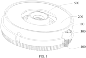
FIG. 1 is an overall structural diagram of a shooting apparatus according to an embodiment of the present invention; -
FIG. 2 is an exploded view ofFIG. 1 according to an embodiment of the present invention; -
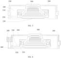
FIG. 3 is a diagram of an internal structure of a shooting apparatus in a first direction according to an embodiment of the present invention; and -
FIG. 4 is a diagram of an internal structure of a shooting apparatus in a second direction according to an embodiment of the present invention. - Reference signs are described as follows:
- 100. first housing,
110. first spiral groove, 120. first mounting component, 130. first loading or unloading space, 140. first accommodating hole, - 200. second housing,
210. first protrusion, 220. second spiral groove, 230. second loading or unloading space, 240. second accommodating hole, 250. avoidance notch, - 300. drive mechanism,
- 400. transmission mechanism,
410. gear shaft, 420. engaging teeth, - 500. lens module,
- 510. extending rod, 520. second protrusion, and 530. base.
- To make the objectives, technical solutions, and advantages of this application clearer, the following clearly and completely describes the technical solutions in the embodiments of this application with reference to the accompanying drawings in the embodiments of this application. Obviously, the described embodiments are merely some but not all of the embodiments of this application. All other embodiments obtained by persons of ordinary skill in the art based on the embodiments of this application without creative efforts shall fall within the protection scope of this application.
- Referring to
FIGs. 1 to 4 , this application discloses a shooting apparatus primarily used for electronic devices such as smartphones and computers, so as to achieve zoom shooting of the electronic devices. The shooting apparatus may include afirst housing 100, asecond housing 200, adrive mechanism 300, and alens module 500. - The
first housing 100 serves as the base housing of the shooting apparatus and is configured to mount other components in the shooting apparatus. Thefirst housing 100 is typically fixed to the electronic device. Specifically, thefirst housing 100 may be provided with a firstaccommodating hole 140, and thesecond housing 200 may be movably disposed in the firstaccommodating hole 140. For example, both thefirst housing 100 and thesecond housing 200 are in a cylindrical shape, and thesecond housing 200 is in clearance fit with thefirst housing 100. - The
lens module 500 is the core component of the shooting apparatus for imaging, such as a regular optical lens, an infrared lens, and a telephoto lens. Thesecond housing 200 serves as the mounting base for thelens module 500 to isolate thelens module 500 from thefirst housing 100. Specifically, thesecond housing 200 may be provided with a secondaccommodating hole 240, and thelens module 500 may be disposed in the secondaccommodating hole 240. - The
second housing 200 serves as the transfer component for drive force to transfer the drive force generated by thedrive mechanism 300 to thelens module 500. In this way, thelens module 500 and thesecond housing 200 integrally form an extending and retracting structure. Such extending and retracting structure is extendable and retractable relative to thefirst housing 100, such that thelens module 500 extends and retracts relative to thefirst housing 100, thus implementing the focus shooting of the shooting apparatus. - Specifically, the
drive mechanism 300 may be drivingly connected to thesecond housing 200, and one of thefirst housing 100 and thesecond housing 200 is provided with afirst spiral groove 110 and the other of thefirst housing 100 and thesecond housing 200 is provided with afirst protrusion 210. Thefirst protrusion 210 is guidedly engaged with thefirst spiral groove 110. For example, thefirst spiral groove 110 is located on an outer periphery of thesecond housing 200, and thefirst protrusion 210 is disposed on an inner wall of the firstaccommodating hole 140. - The
first protrusion 210 is slidable in thefirst spiral groove 110 via thedrive mechanism 300. Specifically, when thedrive mechanism 300 is started, it provides a drive force for thesecond housing 200 to drive thefirst protrusion 210 to move. The guide fit between thefirst protrusion 210 and thefirst spiral groove 110 constrains the movement path of thefirst protrusion 210, allowing it to slide in thefirst spiral groove 110. Under this constraint of thefirst protrusion 210 and thefirst spiral groove 110, thesecond housing 200 performs a spiral lifting motion, allowing at least a portion of thesecond housing 200 to be extendable out of or retractable into the firstaccommodating hole 140. - In this case, the
lens module 500 is movable with thesecond housing 200, for example, to perform a spiral lifting motion with thesecond housing 200. This allows thelens module 500 to also extend out of or retract into thefirst housing 100. - One end of the first
accommodating hole 140 for extension and retraction of thesecond housing 200 is a first aperture, and one end of the firstaccommodating hole 140 back away from the first aperture is a second aperture. The shooting apparatus may further include a base plate, where the base plate can seal the second aperture, and a photosensitive chip may be provided on a side of the base plate facing thelens module 500. The photosensitive chip can capture image information entering thelens module 500, thereby enabling the shooting of the shooting apparatus. The photosensitive chip and thelens module 500 may be sequentially arranged along the optical axis direction of thelens module 500. In this way, when thelens module 500 extends out of or retracts into thefirst housing 100, the distance between thelens module 500 and the photosensitive chip can be changed, allowing for zoom shooting. - In summary, the extendable and retractable arrangement of the
first housing 100, thesecond housing 200, and thelens module 500 can not only achieve zoom of thelens module 500, but also switch the volume size of the shooting apparatus according to the shooting state, reducing the overall volume of the shooting apparatus. This further contributes to the miniaturization and lightweight design of electronic devices equipped with the shooting apparatus. - Furthermore, the first
accommodating hole 140 and the secondaccommodating hole 240 are coaxially arranged along their axis and are both coaxial with the optical axis of thelens module 500. This ensures that the movement of thelens module 500 does not deviate from the optical axis, and thus guarantees better image quality. - In terms of the assembly relationship between the
lens module 500 and thesecond housing 200, thelens module 500 can be fixed in thesecond housing 200 through interference fit or the like, so as to synchronously move with thesecond housing 200. That is, both thelens module 500 and thesecond housing 200 extend and retract relative to thefirst housing 100 in a spiral lifting motion. In this application, thelens module 500 can be movably disposed in the secondaccommodating hole 240, such that thefirst housing 100, thesecond housing 200, and thelens module 500 are all extendable and retractable, further expanding the zoom range of the shooting apparatus. - Specifically, one of the
second housing 200 and thelens module 500 is provided with asecond spiral groove 220 and the other of thesecond housing 200 and thelens module 500 is provided with asecond protrusion 520. For example, thesecond spiral groove 220 is disposed on an outer periphery of thelens module 500 and thesecond protrusion 520 is disposed on the wall of the secondaccommodating hole 240, thesecond protrusion 520 being guidedly engaged with thesecond spiral groove 220. - With this arrangement, the
second protrusion 520 is slidable in thesecond spiral groove 220 via thedrive mechanism 300. The following describes the relevant principle and objective: - As described above, when the
drive mechanism 300 is started, thesecond housing 200 performs a spiral lifting motion relative to thefirst housing 100. For ease of description herein, the spiral lifting motion of thesecond housing 200 can be divided into the lifting motion in the optical axis and rotational motion around the optical axis. - In terms of the lifting motion of the
second housing 200, thelens module 500 performs a lifting motion along with thesecond housing 200 through the guide fit between thesecond protrusion 520 and thesecond spiral groove 220. - In terms of the rotational motion of the
second housing 200, when thesecond housing 200 rotates, thesecond protrusion 520 moves relative to thesecond spiral groove 220. As thesecond housing 200 rotates, the position of thesecond protrusion 520 in thesecond spiral groove 220 is changed. Under the drive of thesecond housing 200, thelens module 500 can perform a lifting motion relative to thesecond housing 200, allowing at least a portion of thelens module 500 to be extendable out of or retractable into the secondaccommodating hole 240. - In summary, under the drive of the
drive mechanism 300, thesecond housing 200 is extendable and retractable relative to thefirst housing 100. In addition, thelens module 500 is also extendable and retractable relative to thesecond housing 200. When both thesecond housing 200 and thelens module 500 are in the extended state, thefirst housing 100, thesecond housing 200, and thelens module 500 are sequentially arranged along the optical axis direction of thelens module 500. This extension and retraction method further expands the zoom range of the shooting apparatus. - Furthermore, in terms of the connection between the
drive mechanism 300 and thesecond housing 200, thedrive mechanism 300 can be directly connected to thesecond housing 200. For example, thedrive mechanism 300 is disposed on the base plate and connected to thesecond housing 200 through hub-to-shaft connection or the like, so as to make thesecond housing 200 rotate. The shooting apparatus of this application may further include atransmission mechanism 400. Thedrive mechanism 300 can be driven by thetransmission mechanism 400 to be connected to thesecond housing 200. The way that thesecond housing 200 is driven directly by thedrive mechanism 300 can make the movement of thesecond housing 200 more stable. - In terms of the specific structure of the
transmission mechanism 400, thetransmission mechanism 400 may include a plurality of engagingteeth 420 and a rack. Thedrive mechanism 300 may be a piston mechanism. The rack is connected to the piston mechanism, and the plurality of engagingteeth 420 are arranged around the periphery of thesecond housing 200, the rack being engaged with the plurality of engagingteeth 420. When the piston mechanism drives the rack to move, the engagement between the rack and engagingteeth 420 drives thesecond housing 200 to perform lifting motion. - In this application, the
transmission mechanism 400 may be provided with agear shaft 410 and a plurality of engagingteeth 420. Thedrive mechanism 300 may be a motor. The plurality of engagingteeth 420 are arranged around the periphery of thesecond housing 200. The plurality of engagingteeth 420 may be of an open-loop structure or a closed-loop structure to form a teeth ring. In addition, the plurality of engagingteeth 420 and thesecond housing 200 may be formed integrally, or may be connected detachably or in another manner in thesecond housing 200. Thegear shaft 410 is rotatably connected to thedrive mechanism 300. For example, the hub-to-shaft connection between thegear shaft 410 and the motor shaft of thedrive mechanism 300 is achieved directly via key connection, spline connection, or the like. Alternatively, thegear shaft 410 is connected to the motor shaft of thedrive mechanism 300 using a coupling, a connection flange, or another structure. Thegear shaft 410 is engaged with the plurality of engagingteeth 420. When rotating, thedrive mechanism 300 drives thegear shaft 410 to rotate and to drive, through engagement, thesecond housing 200 to perform a spiral lifting motion. - It should be noted that, in this arrangement of this application, to ensure that the
gear shaft 410 remains engaged with the plurality of engagingteeth 420 throughout the spiral lifting motion of thesecond housing 200, the tooth width of thegear shaft 410 can be greater than the tooth width of the engagingteeth 420. In terms of the tooth orientation of thegear shaft 410 and the engagingteeth 420, thegear shaft 410 may be a straight-toothed gear shaft to guide the engagingteeth 420, or may be a helical gear shaft to achieve smoother engagement. - More specifically, in terms of the position of the
transmission mechanism 400, the plurality of engagingteeth 420 may be located on the inner wall of the secondaccommodating hole 240. In this way, both thedrive mechanism 300 and thegear shaft 410 are disposed in the secondaccommodating hole 240, which can improve the integration of the shooting apparatus. In this application, the plurality of engagingteeth 420 are disposed on the outer peripheral wall of thesecond housing 200, and afirst mounting component 120 is disposed on thefirst housing 100. Thedrive mechanism 300 is fixed to thefirst mounting component 120. Such arrangement isolates thelens module 500 from thedrive mechanism 300, preventing thedrive mechanism 300, thetransmission mechanism 400, and the like from bumping against thelens module 500 in the focusing process. - In terms of the specific structure of the
first mounting component 120, thefirst mounting component 120 may be a mounting frame to which thedrive mechanism 300 is fixed. In this application, thefirst mounting component 120 is arranged as a mounting groove or mounting opening, and thedrive mechanism 300 is disposed in the mounting groove or mounting opening. This arrangement of thefirst mounting component 120 can improve the integration of the shooting apparatus and further reduce the volume of the shooting apparatus. - Furthermore, the
second housing 200 may be provided with anavoidance notch 250. Thedrive mechanism 300 has a first portion located outside the firstaccommodating hole 140 and a second portion located inside the firstaccommodating hole 140. The first portion of thedrive mechanism 300 is fixed to thefirst mounting component 120, and the second portion of thedrive mechanism 300 is accommodated in theavoidance notch 250, which can further reduce the volume of the shooting apparatus. - More specifically, the
first protrusion 210 may be provided on thesecond housing 200, and thefirst spiral groove 110 may be provided in thefirst housing 100. Thesecond protrusion 520 may be provided on thelens module 500, and thesecond spiral groove 220 may be provided in thesecond housing 200. Thefirst protrusion 210 may be arranged as a sphere and movably embedded on thesecond housing 200, while thesecond protrusion 520 may also be arranged spherical and movably embedded on thelens module 500. This allows for smoother guide fit between thefirst protrusion 210 and thefirst spiral groove 110, as well as between thesecond protrusion 520 and thesecond spiral groove 220, preventing jamming. Certainly, thefirst protrusion 210 and thesecond protrusion 520 may alternatively be designed as a structure such as a slider. - In addition, the
first housing 100 may be provided with a first loading or unloadingspace 130. The first loading or unloadingspace 130 may be a loading or unloading groove formed in the wall of the firstaccommodating hole 140. The loading or unloading groove is specifically a trench structure formed in the inner wall of thefirst housing 100. The trench structure can enhance the overall strength of thefirst housing 100, making thefirst housing 100 less susceptible to deformation under stress. The first loading or unloadingspace 130 may be designed as a loading or unloading notch formed in the wall of the firstaccommodating hole 140. The loading or unloading notch is specifically a recess structure formed in thefirst housing 100 and running along the radial direction of thefirst housing 100. Such the recess structure facilitates processing and manufacturing, so as to assemble related components. - The first loading or unloading
space 130 has a first opening located at an end face of thefirst housing 100, the first loading or unloadingspace 130 communicates with thefirst spiral groove 110, thefirst protrusion 210 slidably coordinates with the first loading or unloadingspace 130, and thefirst protrusion 210 is slidable into or out of the first loading or unloadingspace 130 via the first opening, thus implementing the assembling and disassembling of thefirst housing 100 and thesecond housing 200. - The
second housing 200 may be provided with a second loading or unloadingspace 230. The second loading or unloadingspace 230 is a loading or unloading groove or a loading or unloading notch formed in a wall of the secondaccommodating hole 240, the second loading or unloadingspace 230 communicates with thesecond spiral groove 220, thesecond protrusion 520 slidably coordinates with the second loading or unloadingspace 230, the second loading or unloadingspace 230 has a second opening located at an end face of thesecond housing 200, and thesecond protrusion 520 is slidable into or out of the second loading or unloadingspace 230 via the second opening, thus implementing the assembling and disassembling of thesecond housing 200 and thelens module 500. - In summary, such arrangement improves the convenience of disassembly and assembly between the
first housing 100, thesecond housing 200, and thelens module 500. - It should be noted that to ensure stable movement, the
first protrusion 210 may be provided in plurality and the plurality offirst protrusions 210 are uniformly distributed around the periphery of thesecond housing 200. Similarly, thesecond protrusion 520 may be also provided in plurality and the plurality ofsecond protrusions 520 are uniformly distributed around the periphery of thelens module 500. Certainly, the first loading or unloadingspace 130 and the second loading or unloadingspace 230 each should also be provided in plurality. The first loading or unloadingspaces 130 are in one-to-one correspondence with thefirst protrusions 210, and thesecond protrusions 520 are in one-to-one correspondence with the second loading or unloadingspaces 230. - More specifically, sealing blocks may be added to seal the first loading or unloading
space 130 and the second loading or unloadingspace 230. Specifically, after thefirst housing 100 and thesecond housing 200 are assembled, thefirst protrusion 210 slides into thefirst spiral groove 110. In this case, the sealing block is used to seal the first loading or unloadingspace 130, so as to prevent thefirst housing 100 from being separated from thesecond housing 200. Similarly, after thesecond housing 200 and thelens module 500 are assembled, thesecond protrusion 520 slides into thesecond spiral groove 220. In this case, a sealing block is used to seal the second loading or unloadingspace 230 so as to prevent thesecond housing 200 from being separated from thelens module 500. - Further, the
lens module 500 may include abase 530 and an extendingrod 510 that are interconnected. Thesecond protrusion 520 is disposed at one end of the extendingrod 510 back away from thebase 530. Such arrangement can enhance the adaptability between thelens module 500 and thesecond housing 200. For example, in a case that thebase 530 of thelens module 500 is rectangular and the secondaccommodating hole 240 is circular or there is a large gap between the base 530 of thelens module 500 and the secondaccommodating hole 240, the extendingrod 510 can extend thesecond protrusion 520 outside thebase 530, to ensure the effective fit between thesecond protrusion 520 and thesecond spiral groove 220. - Furthermore, the
first spiral groove 110 may include an arc groove segment and a spiral groove segment that communicate with each other. The arc groove segment and the spiral groove segment are sequentially arranged in a direction leaving the second aperture. Such arrangement allows for sequential extension and retraction of thesecond housing 200 and thelens module 500. Specifically, during zoom shooting, thedrive mechanism 300 is started. In addition, thefirst protrusion 210 enters the arc groove segment and slides in it. In such a case, thesecond housing 200 can rotate, specifically around the optical axis. In addition, through the guide fit between thesecond protrusion 520 and thesecond spiral groove 220, thelens module 500 performs the lifting motion, thus extending by a first distance relative to thefirst housing 100. - As the
drive mechanism 300 continues to operate, thefirst protrusion 210 enters the spiral groove segment and slides in it. In such a case, thesecond housing 200 can perform the spiral rising motion, and extends outside thefirst housing 100. In addition, through the guide fit between thesecond protrusion 520 and thesecond spiral groove 220, thelens module 500 continues to perform the lifting motion. Thus, during the stage where thefirst protrusion 210 slides in the spiral groove segment, thelens module 500 continuously extends by a second distance relative to thefirst housing 100. - In summary, such arrangement allows the
lens module 500 to extend out of thefirst housing 100 and then thesecond housing 200 to extend out of thefirst housing 100. This sequential extension method enhances the control over the zoom shooting of the shooting apparatus. - More specifically, to ensure that when extending and retracting, the
lens module 500 only performs the lifting motion and does not rotate along with the spiral rising motion of thesecond housing 200, and thelens module 500 can be provided with a guide mechanism to constrain the movement of thelens module 500. - Specifically, the
base 530 of thelens module 500 may include a housing component and a main body portion. The main body portion is a portion for imaging by thelens module 500. For example, a lens, a motor, and the like are all disposed on the main body portion. The housing component covers the main body portion for protection. - In terms of the specific structure of the housing component, the housing component can include a base housing and a movable housing. The movable housing is movably disposed on the base housing and guidedly engaged with the base housing. The movable housing can perform a lifting motion along the optical axis relative to the base housing, and the main body portion is disposed in the movable housing. The
second protrusion 520 is disposed on the movable housing and moves along with it. Such arrangement enables thelens module 500 to have extending and retracting capabilities. - In this way, when the
drive mechanism 300 is started, thesecond housing 200 transfers the drive force to thelens module 500. The guide fit between thesecond protrusion 520 and thesecond spiral groove 220 and the mutual constraint between the movable housing and the base housing can drive the movable housing to perform the lifting motion along the optical axis. This prevents the movable housing from rotating during the movement, allowing for better control over focusing and shooting of thelens module 500. - Furthermore, the base housing can be fixed to a base plate and surround the photosensitive chip, optimizing the structure of the shooting apparatus.
- The electronic device disclosed in the embodiments of this application may be a smartphone, a tablet computer, an e-book reader, a wearable device (for example, a smart watch and smart glasses), and the like. A type of the electronic device is not limited specifically in the embodiments of this application.
- The foregoing descriptions are merely embodiments of this application and are not intended to limit this application. For persons skilled in the art, this application may have various changes and variations. Any modification, equivalent replacement, improvement, or the like made without departing from the spirit and principle of this application shall fall within the scope of claims of this application.
Claims (10)
- A shooting apparatus, comprising a first housing (100), a second housing (200), a drive mechanism (300), and a lens module (500), whereinthe first housing (100) is provided with a first accommodating hole (140), the second housing (200) is movably disposed in the first accommodating hole (140), and the drive mechanism (300) is drivingly connected to the second housing (200);the second housing (200) is provided with a second accommodating hole (240), and the lens module (500) is disposed in the second accommodating hole (240);one of the first housing (100) and the second housing (200) is provided with a first spiral groove (110) and an other of the first housing (100) and the second housing (200) is provided with a first protrusion (210), and the first protrusion (210) is guidedly engaged with the first spiral groove (110); andthe first protrusion (210) is slidable in the first spiral groove (110) via the drive mechanism (300), the second housing (200) is capable of performing a spiral lifting motion, at least a portion of the second housing (200) is extendable out of or retractable into the first accommodating hole (140), and the lens module (500) is movable with the second housing (200).
- The shooting apparatus according to claim 1, wherein the lens module (500) is movably disposed in the second accommodating hole (240), one of the second housing (200) and the lens module (500) is provided with a second spiral groove (220) and an other of the second housing (200) and the lens module (500) is provided with a second protrusion (520), and the second protrusion (520) is guidedly engaged with the second spiral groove (220), wherein
the second protrusion (520) is slidable in the second spiral groove (220) via the drive mechanism (300), the lens module (500) is capable of performing a lifting motion, and at least a portion of the lens module (500) is extendable out of or retractable into the second accommodating hole (240). - The shooting apparatus according to claim 1, wherein the shooting apparatus further comprises a transmission mechanism (400), and the drive mechanism (300) is drivingly connected to the second housing (200) via the transmission mechanism (400).
- The shooting apparatus according to claim 3, wherein the transmission mechanism (400) comprises a gear shaft (410) and a plurality of engaging teeth (420), and the drive mechanism (300) is a motor, wherein
the plurality of engaging teeth (420) are arranged around a peripheral portion of the second housing (200), the gear shaft (410) is rotatably connected to the drive mechanism (300), and the gear shaft (410) is engaged with the plurality of engaging teeth (420). - The shooting apparatus according to claim 4, wherein the plurality of engaging teeth (420) are located on a peripheral wall of the second housing (200), a first mounting component (120) is disposed on the first housing (100), and the drive mechanism (300) is fixedly mounted on the first mounting component (120).
- The shooting apparatus according to claim 5, wherein the second housing (200) is provided with an avoidance notch (250), andthe drive mechanism (300) has a first portion located outside the first accommodating hole (140) and a second portion located inside the first accommodating hole (140), whereinthe first portion of the drive mechanism (300) is fixed to the first mounting component (120), and the second portion of the drive mechanism (300) is accommodated in the avoidance notch (250).
- The shooting apparatus according to claim 2, wherein the first protrusion (210) is disposed in the second housing (200), and the first spiral groove (110) is disposed in the first housing (100), wherein
the first housing (100) is provided with a first loading or unloading space (130), the first loading or unloading space (130) has a first opening located at an end face of the first housing (100), the first loading or unloading space (130) communicates with the first spiral groove (110), the first protrusion (210) slidably coordinates with the first loading or unloading space (130), and the first protrusion (210) is slidable into or out of the first loading or unloading space (130) via the first opening. - The shooting apparatus according to claim 2, wherein the second protrusion (520) is disposed in the lens module (500), and the second spiral groove (220) is disposed in the second housing (200), wherein
the second housing (200) is provided with a second loading or unloading space (230), the second loading or unloading space (230) is a loading or unloading groove or a loading or unloading notch formed in a wall of the second accommodating hole (240), the second loading or unloading space (230) communicates with the second spiral groove (220), the second protrusion (520) slidably coordinates with the second loading or unloading space (230), the second loading or unloading space (230) has a second opening located at an end face of the second housing (200), and the second protrusion (520) is slidable into or out of the second loading or unloading space (230) via the second opening. - The shooting apparatus according to claim 8, wherein the lens module (500) comprises a base (530) and an extending rod (510) that are interconnected, and the second protrusion (520) is disposed at one end of the extending rod (510) back away from the base (530).
- An electronic device, comprising the shooting apparatus according to any one of claims 1 to 9.
Applications Claiming Priority (2)
| Application Number | Priority Date | Filing Date | Title |
|---|---|---|---|
| CN202110655890.XA CN113347342B (en) | 2021-06-11 | 2021-06-11 | Imaging device and electronic apparatus |
| PCT/CN2022/097362 WO2022257918A1 (en) | 2021-06-11 | 2022-06-07 | Photographing apparatus and electronic device |
Publications (2)
| Publication Number | Publication Date |
|---|---|
| EP4354845A1 true EP4354845A1 (en) | 2024-04-17 |
| EP4354845A4 EP4354845A4 (en) | 2024-11-20 |
Family
ID=77477088
Family Applications (1)
| Application Number | Title | Priority Date | Filing Date |
|---|---|---|---|
| EP22819516.0A Pending EP4354845A4 (en) | 2021-06-11 | 2022-06-07 | Photographing apparatus and electronic device |
Country Status (4)
| Country | Link |
|---|---|
| US (1) | US12529943B2 (en) |
| EP (1) | EP4354845A4 (en) |
| CN (1) | CN113347342B (en) |
| WO (1) | WO2022257918A1 (en) |
Families Citing this family (4)
| Publication number | Priority date | Publication date | Assignee | Title |
|---|---|---|---|---|
| CN113347342B (en) | 2021-06-11 | 2023-04-18 | 维沃移动通信有限公司 | Imaging device and electronic apparatus |
| CN114500806B (en) * | 2022-01-25 | 2023-07-11 | 深圳市万至达电机制造有限公司 | Miniature zoom lens structure module |
| CN117221696A (en) * | 2022-05-31 | 2023-12-12 | 华为技术有限公司 | Electronic equipment with movable lifting parts |
| CN117425061A (en) * | 2022-07-06 | 2024-01-19 | 华为技术有限公司 | Camera gear and electronic equipment |
Family Cites Families (20)
| Publication number | Priority date | Publication date | Assignee | Title |
|---|---|---|---|---|
| JP4521916B2 (en) * | 2000-02-10 | 2010-08-11 | キヤノン株式会社 | Cam barrel for lens barrel, lens barrel, and camera equipped with the same |
| US20050190283A1 (en) * | 2004-02-24 | 2005-09-01 | Carmel Ish-Shalom | Method and apparatus for macro-focus |
| JP4455350B2 (en) * | 2005-01-18 | 2010-04-21 | キヤノン株式会社 | Imaging device |
| JP5143432B2 (en) * | 2007-01-17 | 2013-02-13 | パナソニック株式会社 | Lens holding structure, lens barrel and camera |
| JP5385029B2 (en) * | 2009-07-06 | 2014-01-08 | パナソニック株式会社 | Cam frame, lens barrel, shake correction device, and image sensor unit |
| CN101951467B (en) * | 2009-07-10 | 2013-08-28 | 鸿富锦精密工业(深圳)有限公司 | Camera module |
| JP5482256B2 (en) * | 2010-02-05 | 2014-05-07 | 株式会社リコー | Lens barrel, imaging device, and portable information terminal device |
| WO2013114898A1 (en) * | 2012-02-02 | 2013-08-08 | パナソニック株式会社 | Lens barrel |
| CN207352245U (en) * | 2017-08-30 | 2018-05-11 | 瑞声科技(新加坡)有限公司 | Camera lens module and electronic equipment |
| CN207867109U (en) * | 2017-09-29 | 2018-09-14 | 东莞市维斗科技股份有限公司 | Automatic focusing focusing lens module |
| KR20190040869A (en) * | 2017-10-11 | 2019-04-19 | 마이크로엑츄에이터(주) | Camera module |
| CN112333351B (en) | 2019-08-05 | 2022-04-05 | 华为技术有限公司 | Camera module and mobile terminal |
| CN213305531U (en) * | 2020-11-25 | 2021-05-28 | 维沃移动通信有限公司 | Electronic equipment |
| CN112532840A (en) * | 2020-11-25 | 2021-03-19 | 维沃移动通信有限公司 | Electronic device |
| CN112526700B (en) * | 2020-12-21 | 2023-05-12 | 维沃移动通信有限公司 | Camera module and electronic equipment |
| CN112637461B (en) * | 2020-12-21 | 2022-08-19 | 维沃移动通信有限公司 | Electronic equipment and camera module |
| CN112672568B (en) * | 2020-12-28 | 2022-07-08 | 维沃移动通信有限公司 | Electronic device |
| KR20250165686A (en) * | 2021-03-11 | 2025-11-26 | 코어포토닉스 리미티드 | Systems for pop-out camera |
| CN113347342B (en) * | 2021-06-11 | 2023-04-18 | 维沃移动通信有限公司 | Imaging device and electronic apparatus |
| KR102776255B1 (en) * | 2022-05-31 | 2025-03-07 | 삼성전기주식회사 | Camera module |
-
2021
- 2021-06-11 CN CN202110655890.XA patent/CN113347342B/en active Active
-
2022
- 2022-06-07 EP EP22819516.0A patent/EP4354845A4/en active Pending
- 2022-06-07 WO PCT/CN2022/097362 patent/WO2022257918A1/en not_active Ceased
-
2023
- 2023-12-08 US US18/533,495 patent/US12529943B2/en active Active
Also Published As
| Publication number | Publication date |
|---|---|
| WO2022257918A1 (en) | 2022-12-15 |
| US20240134251A1 (en) | 2024-04-25 |
| EP4354845A4 (en) | 2024-11-20 |
| US20240231192A9 (en) | 2024-07-11 |
| CN113347342B (en) | 2023-04-18 |
| US12529943B2 (en) | 2026-01-20 |
| CN113347342A (en) | 2021-09-03 |
Similar Documents
| Publication | Publication Date | Title |
|---|---|---|
| US12529943B2 (en) | Photographing apparatus including lens module capable of extending and retracting relative to housing, and electronic device | |
| US7746584B2 (en) | Lens barrel supporting frame, lens retaining structure, lens barrel and camera | |
| CN112637461B (en) | Electronic equipment and camera module | |
| CN112532840A (en) | Electronic device | |
| US8730600B2 (en) | Lens barrel | |
| US7342606B2 (en) | Zoom lens system for camera | |
| JP5838326B2 (en) | Lens barrel and cam mechanism | |
| US20120070138A1 (en) | Lens barrel | |
| CN213305531U (en) | Electronic equipment | |
| EP2101206B1 (en) | Lens barrel | |
| US9348110B2 (en) | Lens barrel and imaging apparatus | |
| WO2022262507A1 (en) | Camera module and electronic device | |
| EP2708928B1 (en) | Lens barrel assembly and photographing apparatus including the same | |
| EP4489382B1 (en) | Electronic device with movable lifting part | |
| CN113534393B (en) | Lens-driven telescopic lens barrel structure, lens-driven device, and camera device | |
| CN115866379B (en) | Camera modules and electronic devices | |
| WO2024046022A1 (en) | Lens assembly, camera and electronic apparatus | |
| CN112702492B (en) | Electronic device | |
| CN103576277B (en) | Lens barrel assembly and the camera including the lens barrel assembly | |
| CN114640735A (en) | Electronic device | |
| EP4407358A1 (en) | Camera module and electronic device | |
| JP4488278B2 (en) | Lens barrel drive mechanism | |
| US20130033761A1 (en) | Lens barrel and imaging device | |
| CN215934935U (en) | Imaging device and mobile terminal | |
| CN120652663A (en) | Optical lens, camera module and electronic equipment |
Legal Events
| Date | Code | Title | Description |
|---|---|---|---|
| STAA | Information on the status of an ep patent application or granted ep patent |
Free format text: STATUS: THE INTERNATIONAL PUBLICATION HAS BEEN MADE |
|
| PUAI | Public reference made under article 153(3) epc to a published international application that has entered the european phase |
Free format text: ORIGINAL CODE: 0009012 |
|
| STAA | Information on the status of an ep patent application or granted ep patent |
Free format text: STATUS: REQUEST FOR EXAMINATION WAS MADE |
|
| 17P | Request for examination filed |
Effective date: 20231214 |
|
| AK | Designated contracting states |
Kind code of ref document: A1 Designated state(s): AL AT BE BG CH CY CZ DE DK EE ES FI FR GB GR HR HU IE IS IT LI LT LU LV MC MK MT NL NO PL PT RO RS SE SI SK SM TR |
|
| DAV | Request for validation of the european patent (deleted) | ||
| DAX | Request for extension of the european patent (deleted) | ||
| REG | Reference to a national code |
Ref country code: DE Ref legal event code: R079 Free format text: PREVIOUS MAIN CLASS: H04N0005225000 Ipc: G02B0007020000 |
|
| A4 | Supplementary search report drawn up and despatched |
Effective date: 20241022 |
|
| RIC1 | Information provided on ipc code assigned before grant |
Ipc: H04N 23/57 20230101ALI20241016BHEP Ipc: G02B 13/00 20060101ALI20241016BHEP Ipc: G02B 7/02 20210101AFI20241016BHEP |