EP4354758A1 - User terminal and method for switching routing in low-earth orbit satellite network - Google Patents
User terminal and method for switching routing in low-earth orbit satellite network Download PDFInfo
- Publication number
- EP4354758A1 EP4354758A1 EP22209049.0A EP22209049A EP4354758A1 EP 4354758 A1 EP4354758 A1 EP 4354758A1 EP 22209049 A EP22209049 A EP 22209049A EP 4354758 A1 EP4354758 A1 EP 4354758A1
- Authority
- EP
- European Patent Office
- Prior art keywords
- user terminal
- satellite
- routing
- information
- leo2
- Prior art date
- Legal status (The legal status is an assumption and is not a legal conclusion. Google has not performed a legal analysis and makes no representation as to the accuracy of the status listed.)
- Pending
Links
- 238000000034 method Methods 0.000 title claims abstract description 20
- 101001089098 Homo sapiens RNA polymerase-associated protein LEO1 Proteins 0.000 claims abstract description 37
- 102100033754 RNA polymerase-associated protein LEO1 Human genes 0.000 claims abstract description 37
- 230000004044 response Effects 0.000 claims description 8
- 230000001960 triggered effect Effects 0.000 claims description 8
- 238000010586 diagram Methods 0.000 description 14
- 230000005540 biological transmission Effects 0.000 description 7
- 238000004891 communication Methods 0.000 description 6
- 230000011664 signaling Effects 0.000 description 6
- 238000006243 chemical reaction Methods 0.000 description 3
- 238000002360 preparation method Methods 0.000 description 3
- 230000003321 amplification Effects 0.000 description 2
- 238000004590 computer program Methods 0.000 description 2
- 238000005516 engineering process Methods 0.000 description 2
- 238000010295 mobile communication Methods 0.000 description 2
- 238000003199 nucleic acid amplification method Methods 0.000 description 2
- 238000001914 filtration Methods 0.000 description 1
- 230000006870 function Effects 0.000 description 1
- 239000013307 optical fiber Substances 0.000 description 1
- 238000000926 separation method Methods 0.000 description 1
- 239000007787 solid Substances 0.000 description 1
Images



Classifications
-
- H—ELECTRICITY
- H04—ELECTRIC COMMUNICATION TECHNIQUE
- H04W—WIRELESS COMMUNICATION NETWORKS
- H04W36/00—Hand-off or reselection arrangements
- H04W36/08—Reselecting an access point
-
- H—ELECTRICITY
- H04—ELECTRIC COMMUNICATION TECHNIQUE
- H04B—TRANSMISSION
- H04B7/00—Radio transmission systems, i.e. using radiation field
- H04B7/14—Relay systems
- H04B7/15—Active relay systems
- H04B7/185—Space-based or airborne stations; Stations for satellite systems
- H04B7/18578—Satellite systems for providing broadband data service to individual earth stations
- H04B7/18584—Arrangements for data networking, i.e. for data packet routing, for congestion control
-
- H—ELECTRICITY
- H04—ELECTRIC COMMUNICATION TECHNIQUE
- H04B—TRANSMISSION
- H04B7/00—Radio transmission systems, i.e. using radiation field
- H04B7/14—Relay systems
- H04B7/15—Active relay systems
- H04B7/185—Space-based or airborne stations; Stations for satellite systems
- H04B7/18521—Systems of inter linked satellites, i.e. inter satellite service
-
- H—ELECTRICITY
- H04—ELECTRIC COMMUNICATION TECHNIQUE
- H04B—TRANSMISSION
- H04B7/00—Radio transmission systems, i.e. using radiation field
- H04B7/14—Relay systems
- H04B7/15—Active relay systems
- H04B7/185—Space-based or airborne stations; Stations for satellite systems
- H04B7/18578—Satellite systems for providing broadband data service to individual earth stations
- H04B7/18597—Arrangements for system physical machines management, i.e. for construction, operations control, administration, maintenance
-
- H—ELECTRICITY
- H04—ELECTRIC COMMUNICATION TECHNIQUE
- H04L—TRANSMISSION OF DIGITAL INFORMATION, e.g. TELEGRAPHIC COMMUNICATION
- H04L45/00—Routing or path finding of packets in data switching networks
- H04L45/02—Topology update or discovery
-
- H—ELECTRICITY
- H04—ELECTRIC COMMUNICATION TECHNIQUE
- H04W—WIRELESS COMMUNICATION NETWORKS
- H04W40/00—Communication routing or communication path finding
- H04W40/02—Communication route or path selection, e.g. power-based or shortest path routing
- H04W40/20—Communication route or path selection, e.g. power-based or shortest path routing based on geographic position or location
-
- H—ELECTRICITY
- H04—ELECTRIC COMMUNICATION TECHNIQUE
- H04B—TRANSMISSION
- H04B7/00—Radio transmission systems, i.e. using radiation field
- H04B7/14—Relay systems
- H04B7/15—Active relay systems
- H04B7/185—Space-based or airborne stations; Stations for satellite systems
- H04B7/18502—Airborne stations
- H04B7/18506—Communications with or from aircraft, i.e. aeronautical mobile service
- H04B7/18508—Communications with or from aircraft, i.e. aeronautical mobile service with satellite system used as relay, i.e. aeronautical mobile satellite service
-
- H—ELECTRICITY
- H04—ELECTRIC COMMUNICATION TECHNIQUE
- H04W—WIRELESS COMMUNICATION NETWORKS
- H04W84/00—Network topologies
- H04W84/02—Hierarchically pre-organised networks, e.g. paging networks, cellular networks, WLAN [Wireless Local Area Network] or WLL [Wireless Local Loop]
- H04W84/04—Large scale networks; Deep hierarchical networks
- H04W84/06—Airborne or Satellite Networks
Definitions
- the invention relates to a communication technology.
- the invention relates to a method for switching routing in a low-earth-orbit satellite network and a user terminal.
- a satellite network architecture includes a data plane, a control plane, and a management plane.
- the data plane includes a low-earth-orbit (LEO) satellite node and a user terminal (UT) accessing the LEO satellite node.
- the control plane includes a geostationary-earth-orbit (GEO) satellite node and is capable of covering the Earth, realizing centralized management and control over the data plane.
- the control plane sends status information of the satellite network to the management plane to obtain structural information of a satellite global network.
- control plane and data plane separation In the next generation mobile communication network, control plane and data plane separation, software-defined network (SDN), and network function virtualization (NFV) have become a paradigm for the communication network architecture and is expected to be transferred to the LEO satellite network in the future.
- SDN software-defined network
- NFV network function virtualization
- a contact time of a LEO satellite with the user terminal is merely a few minutes. Due to such a short contact time, the user terminal may frequently perform handover between several LEO satellites, for a number of times that is more than the number of ground-based mobile networks.
- the control plane or referred to as a network management center, needs to frequently send control signaling to maintain, for example, routing and quality of service parameters, for the data plane of the user terminal.
- delay in communication of the LEO satellite to the control plane is greater than delay in direct connection of a ground base station in the mobile network to a core network through optical fiber.
- the LEO satellite generally needs multiple times of inter-satellite link (ISL) transmission before reaching the control plane.
- ISL inter-satellite link
- the invention provides a method for switching routing in a low-earth-orbit satellite network and a user terminal, in which routing information may be pushed to the satellite by the user terminal and handover may be initiated by the user terminal, to maintain service continuity of the user terminal.
- An embodiment of the invention provides a method for switching routing in a low-earth-orbit satellite network, adapted to a user terminal (UT).
- the method includes the following. Routing information is generated by the user terminal. The routing information is installed into a first routing table of a first satellite. The routing information is installed into a second routing table of a second satellite by the user terminal. The routing information of the first routing table is updated to relay information by the user terminal. The relay information corresponds to the second satellite. Handover from the first satellite to the second satellite is performed by the user terminal.
- An embodiment of the invention provides a user terminal including a transceiver, a storage medium, and a processor coupled to the transceiver and the storage medium.
- the processor is configured to: generate routing information installed into a first routing table of a first satellite; install the routing information into a second routing table of a second satellite; update the routing information of the first routing table to relay information corresponding to the second satellite; and perform handover from the first satellite to the second satellite.
- FIG. 1 is a block diagram of a user terminal according to an embodiment of the invention.
- a user terminal 10 includes a transceiver 110, a storage medium 120, and a processor 130.
- the processor 130 is coupled to the transceiver 110 and the storage medium 120.
- the user terminal 10 may wirelessly communicate with a satellite flying in space.
- the user terminal 10 may be user equipment (UE), for example.
- UE user equipment
- the term "user equipment” of embodiments of the invention may refer to various embodiments, which may include, for example, a mobile station, an advanced mobile station, a server, a client end, a desktop computer, a notebook computer, a network computer, a workstation, a personal digital assistant, a personal computer, a tablet computer, a scanner, a telephone device, a calling device, a camera, a television, a handheld game console, a music device, a wireless sensor, or the like.
- the user terminal 10 may be a stationary computer device operating in a mobile environment such as a bus, a train, an airplane, a ship, an automobile, or the like.
- the user terminal 10 may be a base station in a communication system.
- base station of embodiments of the invention may be, for example, synonymous with a variation or a sub-variation of "gNodeB” (gNB), "eNodeB” (eNB), a node B, an advanced BS (ABS), a transmission reception point (TRP), an unlicensed TRP, a base transceiver system (BTS), an access point, a home BS, a relay station, a scatterer, a repeater, an intermediate node, an intermediary, a satellite-based communication BS, and so on.
- gNodeB gNB
- eNodeB eNodeB
- a node B an advanced BS
- ABS advanced BS
- TRP transmission reception point
- BTS base transceiver system
- access point a home BS
- a relay station a scatterer, a repeater, an intermediate node, an intermediary, a satellite-based communication BS, and so on.
- the transceiver 110 wirelessly transmits downlink signals and receives uplink signals.
- the transceiver 110 may be configured to transmit and receive signals at radio frequencies or at millimeter wave frequencies.
- the transceiver 110 may also perform operations such as low noise amplification, impedance matching, frequency mixing, frequency up-conversion or downconversion, filtering, amplification, and the like.
- the transceiver 110 may include one or more analog-to-digital (A/D) converters and digital-to-analog (D/A) converters that are configured for conversion from an analog signal format to a digital signal format during uplink signal processing, and conversion from a digital signal format to an analog signal format during downlink signal processing.
- the transceiver 110 may further include an antenna array that may include one or more antennas for transmitting and receiving omnidirectional antenna beams or directional antenna beams.
- the storage medium 120 may store a computer program.
- the storage medium 120 is any type of fixed or removable random access memory (RAM), read-only memory (ROM), flash memory, a hard disk drive (HDD), a solid state drive (SSD), or similar elements or a combination thereof.
- RAM random access memory
- ROM read-only memory
- HDD hard disk drive
- SSD solid state drive
- the storage medium 120 is configured to store a plurality of modules, computer programs, or various applications executable by the processor 130.
- the processor 130 is in charge of the whole or part of the operation of the user terminal 10.
- the processor 130 is a central processing unit (CPU), or any other programmable general-purpose or special-purpose micro control unit (MCU), microprocessor, digital signal processor (DSP), programmable controller, application specific integrated circuit (ASIC), graphics processing unit (GPU), image signal processor (ISP), image processing unit (IPU), arithmetic logic unit (ALU), complex programmable logic device (CPLD), field programmable gate array (FPGA), or other similar elements or a combination thereof.
- CPU central processing unit
- MCU microcontrol unit
- DSP digital signal processor
- ASIC application specific integrated circuit
- GPU graphics processing unit
- ISP image signal processor
- IPU image processing unit
- ALU arithmetic logic unit
- CPLD complex programmable logic device
- FPGA field programmable gate array
- FIG. 2 is a flowchart of a method for switching routing in a low-earth-orbit satellite network according to an embodiment of the invention.
- the method shown in FIG. 2 is applicable to the user terminal 10.
- routing information is generated by the user terminal 10.
- the routing information is installed into a first routing table of a first satellite.
- the routing information is installed into a second routing table of a second satellite by the user terminal 10.
- the routing information of the first routing table is updated to relay information by the user terminal 10.
- the relay information corresponds to the second satellite.
- handover from the first satellite to the second satellite is performed by the user terminal 10.
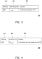
- FIG. 3 is a schematic diagram of routing information according to an embodiment of the invention.
- the data format of routing information 300 may include fields of matching 301, remaining time 302, and operation 303.
- the user terminal 10 may install the routing information 300 into a routing table of a satellite.
- the satellite determines the routing operation of the packet according to the content of the routing information 300.
- the content of the field of matching 301 of the routing information 300 is "UT1", which indicates the routing rule of the packet matching the user terminal "UT1".
- the field of matching 301 may include an identification of the user terminal 10. The identification may be a device identification code of the user terminal 10 or an identification code of the user terminal 10 logging into a satellite network.
- the content of the field of remaining time 302 of the routing information 300 is "t UT 1 ", and this setting value represents a contact time of the user terminal "UT1" with the satellite.
- the contact time t UT 1 as set in the field of remaining time 302 of the routing information 300 is counted down until the contact time t UT 1 is reset to zero.
- the satellite maintains the routing rule of the routing information 300 until the contact time t UT 1 is reset to zero.
- the contact time t UT 1 may be determined according to a flight trajectory model of the satellite and a position of the user terminal "UT1".
- the content of the field of operation 303 of the routing information 300 is "transmission to position of UT1", which indicates that the satellite is to transmit the data of the packet to the position of the user terminal "UT1".
- the position may be a Global Positioning System (GPS) position of the user terminal "UT1".
- GPS Global Positioning System
- the field of operation 303 may also be set to a beam pointing to the GPS position of the user terminal "UT1".
- FIG. 4 is a schematic diagram of relay information according to an embodiment of the invention.
- the data format of relay information 400 may include fields of matching 401, remaining time 402, and operation 403.
- the user terminal 10 may update the routing information 300 stored in the routing table of the satellite to the relay information 400.
- the satellite Upon receipt of a packet, the satellite determines the routing operation of the packet according to the content of the relay information 400.
- the content of the field of matching 401 of the relay information 400 is "UT1", which indicates the routing rule of the packet matching the user terminal "UT1".
- the field of matching 401 may include the identification of the user terminal 10. The identification may be a device identification code of the user terminal 10 or an identification code of the user terminal 10 logging into a satellite network.
- the content of the field of remaining time 402 of the relay information 400 is "T timeout ", and this setting value represents a waiting time of retaining the relay information 400 in the routing table of the satellite during handover performed by the user terminal "UT1" between the satellites.
- the waiting time T timeout as set in the field of remaining time 402 of the relay information 400 is counted down until the waiting time T timeout is reset to zero.
- routing corresponding to the relay information 400 is triggered during the waiting time T timeout , and the waiting time T timeout is re-counted.
- routing corresponding to the relay information 400 is not triggered during the waiting time T timeout , and the relay information 400 is removed from the routing table.
- the content of the field of operation 403 of the relay information 400 is "transmission from inter-satellite link to LEO2", which indicates that the satellite is to transmit the data of the packet from the inter-satellite link to a satellite "LEO2". Accordingly, before handover is completed by the user terminal 10, the data of the packet may be relayed from the current satellite to the next satellite, which prevents the user terminal 10 from losing the packet during handover.
- FIG. 5 is a schematic diagram of a user terminal and a first satellite according to an embodiment of the invention.
- the user terminal UT1 is located on the Earth's surface ES.
- a satellite LEO1 has a signal coverage CV1 on the Earth's surface ES.
- the user terminal UT1 is within the signal coverage CV1 of the satellite LEO1.
- the user terminal UT1 evaluates the contact time t UT 1 of the satellite LEO1 with the next satellite following the satellite LEO1.
- the user terminal UT1 determines the contact time t UT 1 according to a flight trajectory model of the satellite LEO1 and the position of the user terminal UT1.
- the user terminal UT1 determines the next satellite following the satellite LEO1 according to the two-line element (TLE) associated with the satellite LEO1. In an embodiment, the user terminal UT1 generates routing information as in Table 1 below, and installs the routing information into a routing table of the satellite LEO1. Table 1 Matching Remaining time Operation UT1 t UT 1 Transmission to position of UT1
- FIG. 6 is a schematic diagram of a user terminal, a first satellite, and a second satellite during handover preparation according to an embodiment of the invention.
- the user terminal UT1 is located on the Earth's surface ES.
- the satellite LEO1 has the signal coverage CV1 on the Earth's surface ES.
- a satellite LEO2 has a signal coverage CV2 on the Earth's surface ES.
- the user terminal UT1 is within the signal coverage CV1 of the satellite LEO1, and the user terminal UT1 is within the signal coverage CV2 of the satellite LEO2.
- the contact time t UT 1 is reset to zero, the user terminal UT1 prepares for handover to the satellite LEO2.
- the user terminal UT1 determines a new contact time t' UT 1 according to the satellite LEO2. In an embodiment, the user terminal UT1 evaluates the new contact time t' UT 1 of the satellite LEO2 and the next satellite following the satellite LEO2. In an embodiment, the user terminal UT1 determines the new contact time t' UT 1 according to a flight trajectory model of the satellite LEO2 and the position of the user terminal UT1. In an embodiment, the user terminal UT1 determines the next satellite following the satellite LEO2 according to the two-line element (TLE) associated with the satellite LEO2. In an embodiment, the user terminal UT1 updates routing information as in Table 2 below, and installs the updated routing information into a routing table of the satellite LEO2. Table 2 Matching Remaining time Operation UT1 t' UT 1 Transmission to position of UT1
- Table 2 Matching Remaining time Operation UT1 t' UT 1 Transmission to position of UT1
- the packet data of the user terminal UT1 may still be transmitted to the data network through the satellite LEO1. Specifically, before handover from the satellite LEO1 to the satellite LEO2 is completed by the user terminal UT1, some on-the-fly packet data that have been sent by the user terminal UT1 are still transmitted to the satellite LEO1. At this time, it is necessary to modify the routing table of the satellite LEO1 to relay the packet data to the satellite LEO2.
- the user terminal UT1 generates relay information as in Table 3 below, and updates the routing information of the routing table of the satellite LEO1 to the relay information that corresponds to the satellite LEO2. Table 3 Matching Remaining Time Action UT1 T timeout Transmission from inter-satellite link to LEO2
- the waiting time T timeout is re-counted in response to routing corresponding to the relay information being triggered during the waiting time T timeout .
- the relay information is removed from the routing table of the satellite LEO1 in response to routing corresponding to the relay information not being triggered during the waiting time T timeout .
- the user terminal UT1 performs handover from the satellite LEO1 to the satellite LEO2.
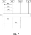
- FIG. 7 is a signaling diagram of a user terminal installing routing information into a second satellite according to an embodiment of the invention.
- the user terminal UT1 receives a message broadcast from the satellite LEO1.
- the user terminal UT1 logs into the satellite LEO1 and receives an ACK packet from the satellite LEO1.
- the user terminal UT1 installs routing information into the routing table of the satellite LEO1. The content of the routing information is as in Table 1 above.
- the user terminal UT1 since the user terminal UT1 has set up the routing through the satellite LEO1, at this time, the user terminal UT1 may access a data network behind a gateway (GW) and connect to the Internet via a default route existing in the satellite LEO1 to the gateway GW.
- GW gateway
- step S705 when the contact time t UT 1 is reset to zero, the user terminal UT1 prepares for handover to the satellite LEO2.
- the user terminal UT1 evaluates the new contact time t' UT 1 of the satellite LEO2 and the next satellite following the satellite LEO2.
- the user terminal UT1 updates the routing information as in Table 2 above, and installs the updated routing information into the routing table of the satellite LEO2.
- step S706 the user terminal UT1 receives an ACK packet from the satellite LEO2.
- FIG. 8 is a signaling diagram for updating routing information of a first satellite to relay information by a user terminal according to an embodiment of the invention.
- the user terminal UT1 updates the routing information of the routing table of the satellite LEO1 to the relay information that corresponds to the satellite LEO2 as in Table 3 above.
- the user terminal UT1 receives an ACK packet from the satellite LEO1.
- the user terminal UT1 performs handover from the satellite LEO1 to the satellite LEO2. Specifically, the user terminal UT1 logs into the satellite LEO2 and receives an ACK packet from the satellite LEO2.
- step S804 since the user terminal UT1 has set up the routing through the satellite LEO2, at this time, the user terminal UT1 may access a data network behind a gateway GW and connect to the Internet via a default route existing in the satellite LEO2 to the gateway GW.
- embodiments of the invention may provide a user terminal-based distributed control plane architecture.
- the user terminal may push the routing information of the user terminal to the satellite currently in service, or to the satellite to which handover is to be performed, and initiate handover by the user terminal when the contact time runs out. Accordingly, in the case of frequent handover by the user terminal between several satellites, the service continuity of the user terminal can be maintained, accordingly improving the user experience.
Landscapes
- Engineering & Computer Science (AREA)
- Computer Networks & Wireless Communication (AREA)
- Signal Processing (AREA)
- Physics & Mathematics (AREA)
- Astronomy & Astrophysics (AREA)
- Aviation & Aerospace Engineering (AREA)
- General Physics & Mathematics (AREA)
- Computing Systems (AREA)
- Mobile Radio Communication Systems (AREA)
- Radio Relay Systems (AREA)
Abstract
A method for switching routing in a low-earth-orbit satellite network, being adapted to a user terminal (UT) (10, UT1), includes the following. Routing information (300) is generated by the UT. The routing information (300) is installed into a first routing table of a first satellite (LEO1). The routing information (300) is installed into a second routing table of a second satellite (LEO2) by the UT. The routing information (300) of the first routing table is updated to relay information (400) by the UT. The relay information (400) corresponds to the second satellite (LEO2). Handover from the first satellite (LEO1) to the second satellite (LEO2) is performed by the UT.
Description
- The invention relates to a communication technology. In particular, the invention relates to a method for switching routing in a low-earth-orbit satellite network and a user terminal.
- With the development of communication technology, a satellite network plays an increasingly important role in the next generation mobile communication network. A satellite network architecture includes a data plane, a control plane, and a management plane. The data plane includes a low-earth-orbit (LEO) satellite node and a user terminal (UT) accessing the LEO satellite node. The control plane includes a geostationary-earth-orbit (GEO) satellite node and is capable of covering the Earth, realizing centralized management and control over the data plane. The control plane sends status information of the satellite network to the management plane to obtain structural information of a satellite global network.
- In the next generation mobile communication network, control plane and data plane separation, software-defined network (SDN), and network function virtualization (NFV) have become a paradigm for the communication network architecture and is expected to be transferred to the LEO satellite network in the future. In an SDN-based multi-layer satellite network architecture, a contact time of a LEO satellite with the user terminal is merely a few minutes. Due to such a short contact time, the user terminal may frequently perform handover between several LEO satellites, for a number of times that is more than the number of ground-based mobile networks. Accordingly, the control plane, or referred to as a network management center, needs to frequently send control signaling to maintain, for example, routing and quality of service parameters, for the data plane of the user terminal.
- Moreover, delay in communication of the LEO satellite to the control plane is greater than delay in direct connection of a ground base station in the mobile network to a core network through optical fiber. In particular, the LEO satellite generally needs multiple times of inter-satellite link (ISL) transmission before reaching the control plane. As a result, the user terminal spend additional time waiting for the exchange of handover control signaling before actually performing handover to the next LEO satellite. Consumption of such additional time seriously affects service continuity of the user terminal and diminish the user experience.
- In view of this, the invention provides a method for switching routing in a low-earth-orbit satellite network and a user terminal, in which routing information may be pushed to the satellite by the user terminal and handover may be initiated by the user terminal, to maintain service continuity of the user terminal.
- An embodiment of the invention provides a method for switching routing in a low-earth-orbit satellite network, adapted to a user terminal (UT). The method includes the following. Routing information is generated by the user terminal. The routing information is installed into a first routing table of a first satellite. The routing information is installed into a second routing table of a second satellite by the user terminal. The routing information of the first routing table is updated to relay information by the user terminal. The relay information corresponds to the second satellite. Handover from the first satellite to the second satellite is performed by the user terminal.
- An embodiment of the invention provides a user terminal including a transceiver, a storage medium, and a processor coupled to the transceiver and the storage medium. The processor is configured to: generate routing information installed into a first routing table of a first satellite; install the routing information into a second routing table of a second satellite; update the routing information of the first routing table to relay information corresponding to the second satellite; and perform handover from the first satellite to the second satellite.
-
-
FIG. 1 is a block diagram of a user terminal according to an embodiment of the invention. -
FIG. 2 is a flowchart of a method for switching routing in a low-earth-orbit satellite network according to an embodiment of the invention. -
FIG. 3 is a schematic diagram of routing information according to an embodiment of the invention. -
FIG. 4 is a schematic diagram of relay information according to an embodiment of the invention. -
FIG. 5 is a schematic diagram of a user terminal and a first satellite according to an embodiment of the invention. -
FIG. 6 is a schematic diagram of a user terminal, a first satellite, and a second satellite during handover preparation according to an embodiment of the invention. -
FIG. 7 is a signaling diagram of a user terminal installing routing information into a second satellite according to an embodiment of the invention. -
FIG. 8 is a signaling diagram for updating routing information of a first satellite to relay information by a user terminal according to an embodiment of the invention. - Some embodiments of the invention accompanied with the drawings will be described in detail below. The same reference numerals in the description below and in the drawings refer to the same or similar elements. These embodiments are only a part of the invention and do not disclose all possible implementations of the invention. More specifically, these embodiments are only examples of the scope of the appended claims of the invention. Wherever possible, elements/members/steps using the same reference numerals in the drawings and embodiments refer to the same or similar parts. Cross-reference may be mutually made to the relevant descriptions of elements/members/steps using the same reference numerals or using the same terms in different embodiments.
-
FIG. 1 is a block diagram of a user terminal according to an embodiment of the invention. Auser terminal 10 includes atransceiver 110, astorage medium 120, and aprocessor 130. Theprocessor 130 is coupled to thetransceiver 110 and thestorage medium 120. Theuser terminal 10 may wirelessly communicate with a satellite flying in space. In an embodiment, theuser terminal 10 may be user equipment (UE), for example. The term "user equipment" of embodiments of the invention may refer to various embodiments, which may include, for example, a mobile station, an advanced mobile station, a server, a client end, a desktop computer, a notebook computer, a network computer, a workstation, a personal digital assistant, a personal computer, a tablet computer, a scanner, a telephone device, a calling device, a camera, a television, a handheld game console, a music device, a wireless sensor, or the like. In some applications, theuser terminal 10 may be a stationary computer device operating in a mobile environment such as a bus, a train, an airplane, a ship, an automobile, or the like. In some embodiments, theuser terminal 10 may be a base station in a communication system. The term "base station" (BS) of embodiments of the invention may be, for example, synonymous with a variation or a sub-variation of "gNodeB" (gNB), "eNodeB" (eNB), a node B, an advanced BS (ABS), a transmission reception point (TRP), an unlicensed TRP, a base transceiver system (BTS), an access point, a home BS, a relay station, a scatterer, a repeater, an intermediate node, an intermediary, a satellite-based communication BS, and so on. - The
transceiver 110 wirelessly transmits downlink signals and receives uplink signals. Thetransceiver 110 may be configured to transmit and receive signals at radio frequencies or at millimeter wave frequencies. Thetransceiver 110 may also perform operations such as low noise amplification, impedance matching, frequency mixing, frequency up-conversion or downconversion, filtering, amplification, and the like. Thetransceiver 110 may include one or more analog-to-digital (A/D) converters and digital-to-analog (D/A) converters that are configured for conversion from an analog signal format to a digital signal format during uplink signal processing, and conversion from a digital signal format to an analog signal format during downlink signal processing. Thetransceiver 110 may further include an antenna array that may include one or more antennas for transmitting and receiving omnidirectional antenna beams or directional antenna beams. - The
storage medium 120 may store a computer program. In an embodiment, thestorage medium 120 is any type of fixed or removable random access memory (RAM), read-only memory (ROM), flash memory, a hard disk drive (HDD), a solid state drive (SSD), or similar elements or a combination thereof. Thestorage medium 120 is configured to store a plurality of modules, computer programs, or various applications executable by theprocessor 130. - The
processor 130 is in charge of the whole or part of the operation of theuser terminal 10. In an embodiment, theprocessor 130 is a central processing unit (CPU), or any other programmable general-purpose or special-purpose micro control unit (MCU), microprocessor, digital signal processor (DSP), programmable controller, application specific integrated circuit (ASIC), graphics processing unit (GPU), image signal processor (ISP), image processing unit (IPU), arithmetic logic unit (ALU), complex programmable logic device (CPLD), field programmable gate array (FPGA), or other similar elements or a combination thereof. -
FIG. 2 is a flowchart of a method for switching routing in a low-earth-orbit satellite network according to an embodiment of the invention. The method shown inFIG. 2 is applicable to theuser terminal 10. In step S201, routing information is generated by theuser terminal 10. The routing information is installed into a first routing table of a first satellite. In step S202, the routing information is installed into a second routing table of a second satellite by theuser terminal 10. In step S203, the routing information of the first routing table is updated to relay information by theuser terminal 10. The relay information corresponds to the second satellite. In step S204, handover from the first satellite to the second satellite is performed by theuser terminal 10. -
FIG. 3 is a schematic diagram of routing information according to an embodiment of the invention. In an embodiment, the data format of routinginformation 300 may include fields of matching 301, remainingtime 302, andoperation 303. Specifically, theuser terminal 10 may install therouting information 300 into a routing table of a satellite. Upon receipt of a packet, the satellite determines the routing operation of the packet according to the content of therouting information 300. - In an embodiment, the content of the field of matching 301 of the
routing information 300 is "UT1", which indicates the routing rule of the packet matching the user terminal "UT1". In an embodiment, the field of matching 301 may include an identification of theuser terminal 10. The identification may be a device identification code of theuser terminal 10 or an identification code of theuser terminal 10 logging into a satellite network. - In an embodiment, the content of the field of remaining
time 302 of therouting information 300 is "t UT1 ", and this setting value represents a contact time of the user terminal "UT1" with the satellite. In the routing table of the satellite, the contact time t UT1 as set in the field of remainingtime 302 of therouting information 300 is counted down until the contact time t UT1 is reset to zero. The satellite maintains the routing rule of therouting information 300 until the contact time t UT1 is reset to zero. In an embodiment, the contact time t UT1 may be determined according to a flight trajectory model of the satellite and a position of the user terminal "UT1". - In an embodiment, the content of the field of
operation 303 of therouting information 300 is "transmission to position of UT1", which indicates that the satellite is to transmit the data of the packet to the position of the user terminal "UT1". In an embodiment, the position may be a Global Positioning System (GPS) position of the user terminal "UT1". In an embodiment, the field ofoperation 303 may also be set to a beam pointing to the GPS position of the user terminal "UT1". -
FIG. 4 is a schematic diagram of relay information according to an embodiment of the invention. In an embodiment, the data format ofrelay information 400 may include fields of matching 401, remainingtime 402, andoperation 403. Specifically, theuser terminal 10 may update therouting information 300 stored in the routing table of the satellite to therelay information 400. Upon receipt of a packet, the satellite determines the routing operation of the packet according to the content of therelay information 400. - In an embodiment, the content of the field of matching 401 of the
relay information 400 is "UT1", which indicates the routing rule of the packet matching the user terminal "UT1". In an embodiment, the field of matching 401 may include the identification of theuser terminal 10. The identification may be a device identification code of theuser terminal 10 or an identification code of theuser terminal 10 logging into a satellite network. - In an embodiment, the content of the field of remaining
time 402 of therelay information 400 is "Ttimeout", and this setting value represents a waiting time of retaining therelay information 400 in the routing table of the satellite during handover performed by the user terminal "UT1" between the satellites. In the routing table of the satellite, the waiting time Ttimeout as set in the field of remainingtime 402 of therelay information 400 is counted down until the waiting time Ttimeout is reset to zero. In an embodiment, routing corresponding to therelay information 400 is triggered during the waiting time Ttimeout, and the waiting time Ttimeout is re-counted. In an embodiment, routing corresponding to therelay information 400 is not triggered during the waiting time Ttimeout, and therelay information 400 is removed from the routing table. - In an embodiment, the content of the field of
operation 403 of therelay information 400 is "transmission from inter-satellite link to LEO2", which indicates that the satellite is to transmit the data of the packet from the inter-satellite link to a satellite "LEO2". Accordingly, before handover is completed by theuser terminal 10, the data of the packet may be relayed from the current satellite to the next satellite, which prevents theuser terminal 10 from losing the packet during handover. -
FIG. 5 is a schematic diagram of a user terminal and a first satellite according to an embodiment of the invention. The user terminal UT1 is located on the Earth's surface ES. A satellite LEO1 has a signal coverage CV1 on the Earth's surface ES. The user terminal UT1 is within the signal coverage CV1 of the satellite LEO1. In an embodiment, after the user terminal UT1 is powered on and detects the satellite LEO1, the user terminal UT1 evaluates the contact time t UT1 of the satellite LEO1 with the next satellite following the satellite LEO1. In an embodiment, the user terminal UT1 determines the contact time t UT1 according to a flight trajectory model of the satellite LEO1 and the position of the user terminal UT1. In an embodiment, the user terminal UT1 determines the next satellite following the satellite LEO1 according to the two-line element (TLE) associated with the satellite LEO1. In an embodiment, the user terminal UT1 generates routing information as in Table 1 below, and installs the routing information into a routing table of the satellite LEO1.Table 1 Matching Remaining time Operation UT1 t UT1 Transmission to position of UT1 -
FIG. 6 is a schematic diagram of a user terminal, a first satellite, and a second satellite during handover preparation according to an embodiment of the invention. The user terminal UT1 is located on the Earth's surface ES. The satellite LEO1 has the signal coverage CV1 on the Earth's surface ES. A satellite LEO2 has a signal coverage CV2 on the Earth's surface ES. The user terminal UT1 is within the signal coverage CV1 of the satellite LEO1, and the user terminal UT1 is within the signal coverage CV2 of the satellite LEO2. In an embodiment, when the contact time t UT1 is reset to zero, the user terminal UT1 prepares for handover to the satellite LEO2. At this time, the user terminal UT1 determines a new contact time t' UT1 according to the satellite LEO2. In an embodiment, the user terminal UT1 evaluates the new contact time t' UT1 of the satellite LEO2 and the next satellite following the satellite LEO2. In an embodiment, the user terminal UT1 determines the new contact time t' UT1 according to a flight trajectory model of the satellite LEO2 and the position of the user terminal UT1. In an embodiment, the user terminal UT1 determines the next satellite following the satellite LEO2 according to the two-line element (TLE) associated with the satellite LEO2. In an embodiment, the user terminal UT1 updates routing information as in Table 2 below, and installs the updated routing information into a routing table of the satellite LEO2.Table 2 Matching Remaining time Operation UT1 t' UT1 Transmission to position of UT1 - It should be noted that during preparation for handover from the satellite LEO1 to the satellite LEO2 by the user terminal UT1, the packet data of the user terminal UT1 may still be transmitted to the data network through the satellite LEO1. Specifically, before handover from the satellite LEO1 to the satellite LEO2 is completed by the user terminal UT1, some on-the-fly packet data that have been sent by the user terminal UT1 are still transmitted to the satellite LEO1. At this time, it is necessary to modify the routing table of the satellite LEO1 to relay the packet data to the satellite LEO2. In an embodiment, the user terminal UT1 generates relay information as in Table 3 below, and updates the routing information of the routing table of the satellite LEO1 to the relay information that corresponds to the satellite LEO2.
Table 3 Matching Remaining Time Action UT1 Ttimeout Transmission from inter-satellite link to LEO2 - In an embodiment, the waiting time Ttimeout is re-counted in response to routing corresponding to the relay information being triggered during the waiting time Ttimeout. In an embodiment, the relay information is removed from the routing table of the satellite LEO1 in response to routing corresponding to the relay information not being triggered during the waiting time Ttimeout .
- In an embodiment, after the routing of the satellite LEO1 and the satellite LEO2 is set up, the user terminal UT1 performs handover from the satellite LEO1 to the satellite LEO2.
-
FIG. 7 is a signaling diagram of a user terminal installing routing information into a second satellite according to an embodiment of the invention. In step S701, the user terminal UT1 receives a message broadcast from the satellite LEO1. In step S702, the user terminal UT1 logs into the satellite LEO1 and receives an ACK packet from the satellite LEO1. In step S703, the user terminal UT1 installs routing information into the routing table of the satellite LEO1. The content of the routing information is as in Table 1 above. In step S704, since the user terminal UT1 has set up the routing through the satellite LEO1, at this time, the user terminal UT1 may access a data network behind a gateway (GW) and connect to the Internet via a default route existing in the satellite LEO1 to the gateway GW. In step S705, when the contact time t UT1 is reset to zero, the user terminal UT1 prepares for handover to the satellite LEO2. The user terminal UT1 evaluates the new contact time t' UT1 of the satellite LEO2 and the next satellite following the satellite LEO2. The user terminal UT1 updates the routing information as in Table 2 above, and installs the updated routing information into the routing table of the satellite LEO2. In step S706, the user terminal UT1 receives an ACK packet from the satellite LEO2. -
FIG. 8 is a signaling diagram for updating routing information of a first satellite to relay information by a user terminal according to an embodiment of the invention. In step S801, the user terminal UT1 updates the routing information of the routing table of the satellite LEO1 to the relay information that corresponds to the satellite LEO2 as in Table 3 above. In step S802, the user terminal UT1 receives an ACK packet from the satellite LEO1. In step S803, the user terminal UT1 performs handover from the satellite LEO1 to the satellite LEO2. Specifically, the user terminal UT1 logs into the satellite LEO2 and receives an ACK packet from the satellite LEO2. In step S804, since the user terminal UT1 has set up the routing through the satellite LEO2, at this time, the user terminal UT1 may access a data network behind a gateway GW and connect to the Internet via a default route existing in the satellite LEO2 to the gateway GW. - In summary of the foregoing, embodiments of the invention may provide a user terminal-based distributed control plane architecture. The user terminal may push the routing information of the user terminal to the satellite currently in service, or to the satellite to which handover is to be performed, and initiate handover by the user terminal when the contact time runs out. Accordingly, in the case of frequent handover by the user terminal between several satellites, the service continuity of the user terminal can be maintained, accordingly improving the user experience.
Claims (20)
- A method for switching routing in a low-earth-orbit satellite network, being adapted to a user terminal (10, UT1), the method comprising:generating, by the user terminal (10, UT1), routing information (300) installed into a first routing table of a first satellite (LEO1);installing, by the user terminal (10, UT1), the routing information (300) into a second routing table of a second satellite (LEO2);updating, by the user terminal (10, UT1), the routing information (300) of the first routing table to relay information (400) corresponding to the second satellite (LEO2); andperforming, by the user terminal (10, UT1), handover from the first satellite (LEO1) to the second satellite (LEO2).
- The method of claim 1, wherein the routing information (300) comprises an identification of the user terminal (10, UT1).
- The method of claim 1 or 2, wherein the routing information (300) comprises a position of the user terminal (10, UT1).
- The method of any one of claims 1 to 3, wherein the routing information (300) comprises a first contact time (tUT1 ).
- The method of claim 4, wherein the first contact time (tUT1 ) is determined according to a flight trajectory model of the first satellite (LEO1) and a position of the user terminal (10, UT1).
- The method of claim 4, further comprising:determining a second contact time (t'UT1 ) in response to the first contact time (tUT1 ) being reset to zero; andupdating the routing information (300) according to the second contact time (t'UT1 ).
- The method of claim 6, wherein the second contact time (t'UT1 ) is determined according to a flight trajectory model of the second satellite (LEO2) and a position of the user terminal (10, UT1).
- The method of any one of claims 1 to 7, wherein the relay information (400) comprises a waiting time (Ttimeout ).
- The method of claim 8, further comprising:
re-counting the waiting time (Ttimeout ) in response to routing corresponding to the relay information (400) being triggered during the waiting time (Ttimeout ). - The method of claim 8, further comprising:
removing the relay information (400) from the first routing table in response to routing corresponding to the relay information (400) not being triggered during the waiting time (Ttimeout ). - A user terminal (10, UT1), comprising:a transceiver (110);a storage medium (120); anda processor (130) coupled to the transceiver (110) and the storage medium (120), the processor (130) being configured to:generate routing information (300) installed into a first routing table of a first satellite (LEO1);install the routing information (300) into a second routing table of a second satellite (LEO2);update the routing information (300) of the first routing table to relay information (400) corresponding to the second satellite (LEO2); andperform handover from the first satellite (LEO1) to the second satellite (LEO2).
- The user terminal (10, UT1) of claim 11, wherein the routing information (300) comprises an identification of the user terminal (10, UT1).
- The user terminal (10, UT1) of claim 11 or 12, wherein the routing information (300) comprises a position of the user terminal (10, UT1).
- The user terminal (10, UT1) of any one of claims 11 to 13, wherein the routing information (300) comprises a first contact time (tUT1 ).
- The user terminal (10, UT1) of claim 14, wherein the first contact time (tUT1 ) is determined according to a flight trajectory model of the first satellite (LEO1) and a position of the user terminal (10, UT1).
- The user terminal (10, UT1) of claim 14, wherein the processor (130) is further configured to:determine a second contact time (t'UT1 ) in response to the first contact time (tUT1 ) being reset to zero; andupdate the routing information (300) according to the second contact time (t'UT1 ).
- The user terminal (10, UT1) of claim 16, wherein the second contact time (t'UT1 ) is determined according to a flight trajectory model of the second satellite (LEO2) and a position of the user terminal (10, UT1).
- The user terminal (10, UT1) of any one of claims 11 to 17, wherein the relay information (400) comprises a waiting time (Ttimeout ).
- The user terminal (10, UT1) of claim 18, wherein the processor (130) is further configured to:
re-count the waiting time (Ttimeout ) in response to routing corresponding to the relay information (400) being triggered during the waiting time (Ttimeout ). - The user terminal (10, UT1) of claim 18, wherein the processor (130) is further configured to:
remove the relay information (400) from the first routing table in response to routing corresponding to the relay information (400) not being triggered during the waiting time (Ttimeout ).
Applications Claiming Priority (1)
| Application Number | Priority Date | Filing Date | Title |
|---|---|---|---|
| TW111139041A TWI849533B (en) | 2022-10-14 | 2022-10-14 | User terminal and method for switching routing in low-earth orbit satellite network |
Publications (1)
| Publication Number | Publication Date |
|---|---|
| EP4354758A1 true EP4354758A1 (en) | 2024-04-17 |
Family
ID=84361588
Family Applications (1)
| Application Number | Title | Priority Date | Filing Date |
|---|---|---|---|
| EP22209049.0A Pending EP4354758A1 (en) | 2022-10-14 | 2022-11-23 | User terminal and method for switching routing in low-earth orbit satellite network |
Country Status (4)
| Country | Link |
|---|---|
| US (1) | US20240129821A1 (en) |
| EP (1) | EP4354758A1 (en) |
| CN (1) | CN117895989A (en) |
| TW (1) | TWI849533B (en) |
Citations (1)
| Publication number | Priority date | Publication date | Assignee | Title |
|---|---|---|---|---|
| US20210306069A1 (en) * | 2018-12-14 | 2021-09-30 | Huawei Technologies Co., Ltd. | Satellite network communication method, related apparatus, and system |
Family Cites Families (6)
| Publication number | Priority date | Publication date | Assignee | Title |
|---|---|---|---|---|
| WO2011085028A2 (en) * | 2010-01-06 | 2011-07-14 | Datasat Technologies Ag | Method and system for providing information access, multimedia content access, and phone connectivity |
| CN106230719B (en) * | 2016-07-29 | 2019-06-11 | 西安交通大学 | A LEO satellite network link switching management method based on link remaining time |
| CN106549703B (en) * | 2016-10-26 | 2019-09-06 | 北京邮电大学 | Method and system for low-orbit satellite communication in space-ground integrated network |
| CN113133062B (en) * | 2019-12-30 | 2022-05-17 | 大唐移动通信设备有限公司 | Inter-satellite switching method and device, terminal and network side equipment |
| CN112054823B (en) * | 2020-09-10 | 2022-04-15 | 重庆邮电大学 | A low-orbit satellite communication switching method |
| CN113258987A (en) * | 2021-05-13 | 2021-08-13 | 重庆邮电大学 | Communication switching method between low-orbit satellite reverse seams |
-
2022
- 2022-10-14 TW TW111139041A patent/TWI849533B/en active
- 2022-11-23 EP EP22209049.0A patent/EP4354758A1/en active Pending
-
2023
- 2023-01-04 CN CN202310009939.3A patent/CN117895989A/en active Pending
- 2023-02-22 US US18/172,314 patent/US20240129821A1/en active Pending
Patent Citations (1)
| Publication number | Priority date | Publication date | Assignee | Title |
|---|---|---|---|---|
| US20210306069A1 (en) * | 2018-12-14 | 2021-09-30 | Huawei Technologies Co., Ltd. | Satellite network communication method, related apparatus, and system |
Also Published As
| Publication number | Publication date |
|---|---|
| TW202416682A (en) | 2024-04-16 |
| CN117895989A (en) | 2024-04-16 |
| US20240129821A1 (en) | 2024-04-18 |
| TWI849533B (en) | 2024-07-21 |
Similar Documents
| Publication | Publication Date | Title |
|---|---|---|
| US11876602B2 (en) | Communication method, apparatus, and system based on satellite network | |
| US10700769B2 (en) | Satellite-based narrow-band communication | |
| CN115462130A (en) | Signaling efficiency improvement in non-terrestrial networks | |
| KR102877084B1 (en) | Method and apparatus for mobility management of a terminal in a satellite communication system | |
| CN113133062A (en) | Inter-satellite switching method and device, terminal and network side equipment | |
| CN106817763A (en) | The register method of hierarchical network, device and system | |
| JP2024530871A (en) | User equipment, user equipment method, network node, and network node method | |
| US20230396330A1 (en) | Beam selection in non-terrestrial networks | |
| CN118646474B (en) | Communication method, communication device, and computer storage medium | |
| JP2025514830A (en) | Method, user equipment and network node | |
| CN115707044B (en) | Non-land network switching method and device, storage medium and electronic equipment | |
| US12395946B2 (en) | Power control for flying base station | |
| WO2026021145A1 (en) | Communication method and apparatus | |
| US20240129821A1 (en) | User terminal and method for switching routing in low-earth orbit satellite network | |
| CN117441389A (en) | Uplink transmission method, device, equipment and storage medium | |
| US20250185100A1 (en) | Transfer of communication device to connected state according to operating plan of base station | |
| US12309693B2 (en) | Control of operating state of terrestrial base station via non-terrestrial base station | |
| US20250150159A1 (en) | Determining communication ratio based on non-terrestrial communication quality information | |
| KR20240142004A (en) | Method and apparatus for signaling load balancing in non-terrestrial network | |
| CN113777632A (en) | A precise single point positioning method and system based on satellite channel transmission | |
| WO2025160808A1 (en) | Support for store and forward mode in ntn | |
| US20250261001A1 (en) | Setting relay radio wave in control of relay station by network | |
| US20240357453A1 (en) | Communication control for intermediate station | |
| CN116170865B (en) | Tracking area updating method, device, equipment and storage medium | |
| US20260143395A1 (en) | Method for cell handover and communication device |
Legal Events
| Date | Code | Title | Description |
|---|---|---|---|
| PUAI | Public reference made under article 153(3) epc to a published international application that has entered the european phase |
Free format text: ORIGINAL CODE: 0009012 |
|
| STAA | Information on the status of an ep patent application or granted ep patent |
Free format text: STATUS: REQUEST FOR EXAMINATION WAS MADE |
|
| 17P | Request for examination filed |
Effective date: 20240117 |
|
| AK | Designated contracting states |
Kind code of ref document: A1 Designated state(s): AL AT BE BG CH CY CZ DE DK EE ES FI FR GB GR HR HU IE IS IT LI LT LU LV MC ME MK MT NL NO PL PT RO RS SE SI SK SM TR |