EP4354708A1 - Motor rotor - Google Patents
Motor rotor Download PDFInfo
- Publication number
- EP4354708A1 EP4354708A1 EP22819885.9A EP22819885A EP4354708A1 EP 4354708 A1 EP4354708 A1 EP 4354708A1 EP 22819885 A EP22819885 A EP 22819885A EP 4354708 A1 EP4354708 A1 EP 4354708A1
- Authority
- EP
- European Patent Office
- Prior art keywords
- permanent magnet
- rotor
- mounting groove
- rotor yoke
- inclined surfaces
- Prior art date
- Legal status (The legal status is an assumption and is not a legal conclusion. Google has not performed a legal analysis and makes no representation as to the accuracy of the status listed.)
- Withdrawn
Links
Images


Classifications
-
- H—ELECTRICITY
- H02—GENERATION; CONVERSION OR DISTRIBUTION OF ELECTRIC POWER
- H02K—DYNAMO-ELECTRIC MACHINES
- H02K1/00—Details of the magnetic circuit
- H02K1/06—Details of the magnetic circuit characterised by the shape, form or construction
- H02K1/22—Rotating parts of the magnetic circuit
- H02K1/27—Rotor cores with permanent magnets
- H02K1/2706—Inner rotors
- H02K1/272—Inner rotors the magnetisation axis of the magnets being perpendicular to the rotor axis
- H02K1/274—Inner rotors the magnetisation axis of the magnets being perpendicular to the rotor axis the rotor consisting of two or more circumferentially positioned magnets
- H02K1/2753—Inner rotors the magnetisation axis of the magnets being perpendicular to the rotor axis the rotor consisting of two or more circumferentially positioned magnets the rotor consisting of magnets or groups of magnets arranged with alternating polarity
- H02K1/278—Surface mounted magnets; Inset magnets
-
- H—ELECTRICITY
- H02—GENERATION; CONVERSION OR DISTRIBUTION OF ELECTRIC POWER
- H02K—DYNAMO-ELECTRIC MACHINES
- H02K2201/00—Specific aspects not provided for in the other groups of this subclass relating to the magnetic circuits
- H02K2201/06—Magnetic cores, or permanent magnets characterised by their skew
Definitions
- the present invention relates to a motor rotor which includes a rotor yoke and a permanent magnet bonded to an outer peripheral surface of the rotor yoke.
- Patent Literature 1 listed below discloses a conventionally known example of a motor rotor including a rotor yoke and a permanent magnet bonded to an outer peripheral surface of the rotor yoke.
- This rotor is manufactured by forming a plating layer of a material such as copper or nickel on the entire surface of the permanent magnet, placing the permanent magnet with the plating layer thereon in contact with the outer peripheral surface of the rotor yoke, and then radiating a laser beam toward the contact contour of the permanent magnet. That is to say, the plating layer formed on the surface of the permanent magnet is melted by the laser beam radiated toward the linear contact contour of the permanent magnet, so that the melted metal (copper or nickel) acts as a brazing material to bond (braze) the permanent magnet to the outer peripheral surface of the rotor yoke.
- a plating layer of a material such as copper or nickel
- the brazing of the permanent magnet to the outer peripheral surface of the rotor yoke enables the permanent magnet to be firmly joined to the rotor yoke; therefore, the rotor is improved in the joining strength and durability, including the thermal shock resistance, at high temperature and high speed rotation.
- Patent Literature 1 International Publication No. WO 2004/068673
- the present invention has been achieved in view of the above-described circumstances and an object of the invention is to provide a motor rotor which is improved such that a permanent magnet is less likely than that in the conventional rotor to come off from a rotor yoke even when a strong centrifugal force acts thereon.
- the present invention provides a motor rotor including:
- the two inner walls of the mounting groove and the two sides of the permanent magnet opposed to the two inner walls are bonded by brazing, that is to say, bonded by a brazing material embedded between the two inner walls of the mounting groove and the two sides of the permanent magnet.
- the bonding surface where the rotor yoke and the permanent magnet are bonded to each other is increased as compared with the above-described conventional rotor in which the rotor yoke and the permanent magnet are bonded together by brazing the linear contact contour of the permanent magnet contacting with the rotor yoke, so that the bonding strength between the rotor yoke and the permanent magnet is increased. Consequently, as compared with the conventional rotor, the rotor according to the first aspect effectively prevents the permanent magnet from coming off from the rotor yoke, even when a strong centrifugal force generated by high-speed rotation of the rotor acts on the permanent magnet.
- At least the two sides of the permanent magnet opposed to the two inner walls of the mounting groove are formed as inclined surfaces tapering from the bonded side toward a side opposite to the bonded side of the permanent magnet.
- the brazing material embedded between the two inner walls of the mounting groove and the two sides of the permanent magnet through the brazing uses not only its bonding force but also a mechanical acting force produced by engagement with the permanent magnet to restrain the permanent magnet from coming off outward from the rotor yoke due to a centrifugal force.
- the rotor according to this second aspect more effectively prevents coming-off of the permanent magnet from the rotor yoke than the conventional rotor.
- At least the two inner walls of the mounting groove opposed to the two sides of the permanent magnet are formed as inclined surfaces tapering toward an open side of the mounting groove.
- the brazing material embedded between the two inner walls of the mounting groove and the two sides of the permanent magnet through the brazing uses not only its bonding force but also a mechanical acting force produced by engagement with the permanent magnet to restrain the permanent magnet from coming off outward from the rotor yoke due to a centrifugal force.
- the rotor according to this third aspect also more effectively prevents coming-off of the permanent magnet from the rotor yoke than the conventional rotor.
- a bottom surface of the bonded side of the permanent magnet may be bonded with an adhesive to a bottom surface of the mounting groove.
- the bonding surface where the rotor yoke and the permanent magnet are bonded to each other is increased as compared with that in the above-described conventional rotor, so that the bonding strength between the rotor yoke and the permanent magnet is increased. Consequently, as compared with the conventional rotor, the rotor according to the present invention effectively prevents the permanent magnet from coming off from the rotor yoke, even when a strong centrifugal force generated by high-speed rotation of the rotor acts on the permanent magnet.
- the rotor 1 is constituted by a tubular rotor yoke 2 and permanent magnets 10.
- the rotor yoke 2 has an outer peripheral surface of a polygonal shape (in particular, an octagonal shape) and has an inner peripheral surface of a cylindrical shape.
- the permanent magnets 10 are bonded to surfaces (mounting surfaces) 2a of the outer periphery of the rotor yoke 2.
- the shape of the rotor yoke 2 is not limited to an octagonal shape.
- the rotor yoke 2 may have a polygonal shape corresponding to the number of permanent magnets 10 to be provided thereon or may have an outer peripheral surface of a cylindrical shape that is similar to the inner peripheral surface.
- the rotor yoke 2 has a mounting groove 3 as well as a bonding groove 5 for an adhesive 6 in each mounting surface 2a thereof.
- the mounting groove 3a is formed substantially along an axis 2b of the rotor yoke 2 and opened to two end surfaces 2c and 2d of the rotor yoke 2.
- the bonding groove 5 is formed along the mounting groove 3 in a bottom surface 3c of the mounting groove 3 and opened to the two end surfaces 2c and 2d of the rotor yoke 2.
- Two inner walls 3a and 3b of the mounting groove 3 are formed as inclined surfaces tapering toward the open side opposite to the bottom surface 3c of the mounting groove 3.
- Two inner walls 5a and 5b of the bonding groove 5 are formed as surfaces vertical to a bottom surface 5c of the bonding groove 5.
- Each permanent magnet 10 is composed of a prismatic body having a trapezoidal cross section and the longest side (base) thereof is inserted in the mounting groove 3. That is to say, two sides 11 and 12 of the permanent magnet 10 opposed to the two inner walls 3a and 3b of the mounting groove 3 are formed as inclined surfaces tapering from the base side toward the opposite side of the permanent magnet 10, and the base side of the permanent magnet 10 is inserted in the mounting groove 3. In one mounting groove 3, a plurality of (in this example, seven) permanent magnets 10 are inserted and mounted continuously with no gaps as shown in FIG. 4 .
- a clearance enough for brazing is formed between each inner wall 3a, 3b of the mounting groove 3 and each side 11, 12 of the permanent magnet 10 opposed thereto.
- the width of the opening of the mounting groove 3 is smaller than the width of the base (bottom surface) of the permanent magnet 10, so that engagement between the mounting groove 3 and the permanent magnet 10 inserted in the mounting groove 3 prevents the permanent magnet 10 from slipping out radially through the opening of the mounting groove 3.
- a bottom surface 13 of the permanent magnet 10 is bonded to the rotor yoke 2 by the adhesive 6 that is applied in the bonding groove 5. Further, each inner wall 3a, 3b of the mounting groove 3 and each side 11, 12 of the permanent magnet 10 opposed thereto are bonded therebetween by brazing (by a brazing material 4).
- the brazing may use, for example, a known laser brazing method.
- the brazing material may be, for example, a brazing wire (copper/silicon 3% alloy).
- the adhesive 6 may be, for example, a epoxy resin adhesive or a silicone adhesive.
- the mounting groove 3 and the bonding groove 5 are formed slightly obliquely with respect to the axis of the rotor yoke 2 and the permanent magnets 10 are also arranged slightly obliquely. This configuration prevents pulsation of the rotor 1 as assembled in a motor.
- the two inner walls 3a, 3b of the mounting groove 3 and the two sides 11, 12 of the permanent magnet 10 opposed to the two inner walls 3a, 3b are bonded by brazing, that is to say, bonded by the brazing material embedded between the two inner walls 3a, 3b of the mounting groove 3 and the two sides 11, 12 of the permanent magnet 10.
- the bonding surface where the rotor yoke 2 and the permanent magnet 10 are bonded to each other is increased as compared with that in the above-described conventional rotor, so that the bonding strength between the rotor yoke 2 and the permanent magnet 10 is increased. Consequently, as compared with the conventional rotor, the rotor 1 effectively prevents the permanent magnet 10 from coming off from the rotor yoke 2, even when a strong centrifugal force generated by high-speed rotation of the rotor 1 acts on the permanent magnet 10.
- the two inner walls 3a, 3b of the mounting groove 3 are formed as inclined surfaces tapering toward the open side opposite to the bottom surface 3c of the mounting groove 3 and the two sides 11, 12 of the permanent magnet 10 opposed to the two inner walls 3a, 3b of the mounting groove 3 are also formed as inclined surfaces tapering from the base side toward the opposite side of the permanent magnet 10.
- the brazing material 4 embedded between the two inner walls 3a, 3b of the mounting groove 3 and the two sides 11, 12 of the permanent magnet 10 through the brazing to uses not only its bonding force but also a mechanical acting force produced by the engagement between the mounting groove 3 of the rotor yoke 2 and the permanent magnet 10 to restrain the permanent magnet 10 from coming off outward from the rotor yoke 2 due to a centrifugal force.
- the rotor 1 according to this embodiment more effectively prevents coming-off of the permanent magnet 10 from the rotor yoke 2 than the conventional rotor.
- the width of the opening of the mounting groove 3 is smaller than the width of the base (bottom surface) of the permanent magnet 10. Therefore, the permanent magnet 10 inserted in the mounting groove 3 is, by virtue of the engagement therebetween, structurally unable to slip out radially through the opening of the mounting groove 3.
- the rotor 1 according to this embodiment reliably prevents the permanent magnet 10 from coming off from the rotor yoke 2, even when a strong centrifugal force generated by high-speed rotation of the rotor 1 acts on the permanent magnet 10.
- the bottom surface 13 of the permanent magnet 10 is bonded to the rotor yoke 2 by the adhesive 6 applied in the bonding groove 5. Therefore, the permanent magnet 10 is bonded to the rotor yoke 2 not only by the bonding action of the brazing material 4 but also by the adhesive 6. Thus, the permanent magnet 10 is more firmly bonded to the rotor yoke 2 by the combined bonding action of the brazing material 4 and adhesive 6.
- the rotor 21 according to this embodiment has a rotor yoke 22 having a mounting groove 23 that differs in cross-sectional shape from that of the rotor yoke 2 of the rotor 1 according to the first embodiment.
- the other structures of the rotor 21 are identical to those of the rotor 1.
- the mounting groove 23 has a shape in which two inner walls 23a and 23b are formed as inclined surfaces (lower inclined surfaces 23a 1 and 23b 1 ) tapering from a bottom surface 23c toward the opposite open side of the mounting groove 23 and then formed as inclined surfaces (upper inclined surfaces 23a 2 and 23b 2 ) widening toward the open side of the mounting groove 23.
- the permanent magnet 10 is inserted between the lower inclined surfaces 23a 1 and 23b 1 of the mounting groove 23, and each side 11, 12 of the permanent magnet 10 and each upper inclined surface 23a 2 , 23b 2 of the mounting groove 23 are brazed therebetween by a brazing material 24.
- the permanent magnet 10 can be slid along the mounting groove 23; however, no unnecessary gaps are formed between the lower inclined surfaces 23a 1 , 23b 1 of the mounting groove 23 and the two sides 11, 12 of the permanent magnet 10.
- the reference numeral 22a denotes a mounting surface on an outer peripheral surface of the rotor yoke 22.
- the bonding force of the brazing material 24 embedded between the upper inclined surfaces 23a 2 , 23b 2 of the mounting groove 23 and the two sides 11, 12 of the permanent magnet 10 prevents the permanent magnet 10 from coming off outward from the rotor yoke 21 and also prevents the permanent magnet 10 from moving along the mounting groove 23. Further, the engagement between the lower inclined surfaces 23a 1 , 23b 1 of the mounting groove 23 and the two sides 11, 12 of the permanent magnet 10 structurally prevents the permanent magnet 10 from coming off from the rotor yoke 2. Thus, the rotor 21 according to this embodiment reliably prevents the permanent magnet 10 from coming off from the rotor yoke 22.
- the rotor 31 according to this embodiment has a rotor yoke 32 having a mounting groove 33 that differs in cross-sectional shape from that of the rotor yoke 2 of the rotor 1 according to the first embodiment.
- the other structures of the rotor 31 are identical to those of the rotor 1.
- two inner walls 33a and 33b of the rotor yoke 32 in this embodiment are formed as surfaces vertical to a bottom surface 33c of the rotor yoke 32 similarly to those of the bonding groove 5.
- Each side 11, 12 of the permanent magnet 10 and each inner wall 33a, 33b of the mounting groove 33 are brazed therebetween by a brazing material 34.
- the reference numeral 32a denotes a mounting surface on an outer peripheral surface of the rotor yoke 32.
- the bonding surface where the rotor yoke 32 and the permanent magnet 10 are bonded to each other is increased as compared with the above-described conventional rotor, so that the bonding strength between the rotor yoke 32 and the permanent magnet 10 is increased. Consequently, as compared with the conventional rotor, the rotor 31 effectively prevents the permanent magnet 10 from coming off from the rotor yoke 32, even when a strong centrifugal force generated by high-speed rotation of the rotor 31 acts on the permanent magnet 10.
- the two sides 11, 12 of the permanent magnet 10 opposed to the two inner walls 33a, 33b of the mounting groove 33 are formed as inclined surfaces tapering from the base side toward the opposite side of the permanent magnet 10. Therefore, the brazing material 34 embedded between the two inner walls 33a, 33b of the mounting groove 33 and the two sides 11, 12 of the permanent magnet 10 through the brazing uses not only its bonding force but also a mechanical acting force produced by the engagement between the mounting groove 33 of the rotor yoke 32 and the permanent magnet 10 to restrain the permanent magnet 10 from coming off outward from the rotor yoke 32.
- the rotor 31 according to this embodiment more effectively prevents coming-off of the permanent magnet 10 from the rotor yoke 32 than the conventional rotor.
- the rotor 41 according to this embodiment has a permanent magnet 45 that differs in cross-sectional shape from the permanent magnet 10 of the rotor 1 according to the first embodiment.
- the other structures of the rotor 41 are identical to those of the rotor 1.
- the permanent magnet 45 in this embodiment has a top having a convex curved surface.
- the permanent magnet 45 having this shape provides a high magnetic flux density.
- the reference numerals 46 and 47 respectively denote two sides of the permanent magnet 45 and the reference numeral 49 denotes a bottom surface of the permanent magnet 45.
- the rotor 51 according to this embodiment has a permanent magnet 55 that differs in cross-sectional shape from the permanent magnet 10 of the rotor 31 according to the third embodiment.
- the other structures of the rotor 51 are identical to those of the rotor 1.
- the permanent magnet 55 in this embodiment has a rectangular cross section.
- Each side 56, 57 of the permanent magnet 55 and each inner wall 33a, 33b of the mounting groove 33 are brazed therebetween by the brazing material 34.
- the reference numeral 58 denotes a bottom surface of the permanent magnet 55.
- the bonding surface where the rotor yoke 32 and the permanent magnet 55 are bonded to each other is increased as compared with the above-described conventional rotor, so that the bonding strength between the rotor yoke 32 and the permanent magnet 55 is increased. Consequently, as compared with the conventional rotor, the rotor 51 effectively prevents the permanent magnet 55 from coming off from the rotor yoke 2, even when a strong centrifugal force generated by high-speed rotation of the rotor 51 acts on the permanent magnet 55.
- the width of the opening of the mounting groove 3 is set to be smaller than the width of the base (bottom surface) of the permanent magnet 10, 45.
- the present invention is not limited thereto. Where the bonding strength between the rotor yoke 2 and the permanent magnet 10, 45 is sufficiently high, the width of the opening of the mounting groove 3 may be set to be larger than the width of the base (bottom surface) of the permanent magnet 10, 45.
- the number of permanent magnets 10, 45, 55 is not limited to seven and may be less than or more than seven.
- the mounting groove 33 may be replaced by the mounting groove 3 in the first and fourth embodiments.
Landscapes
- Engineering & Computer Science (AREA)
- Power Engineering (AREA)
- Permanent Field Magnets Of Synchronous Machinery (AREA)
Abstract
Description
- 0001 The present invention relates to a motor rotor which includes a rotor yoke and a permanent magnet bonded to an outer peripheral surface of the rotor yoke.
- 0002 International Publication No.
WO 2004/068673 (Patent Literature 1 listed below) discloses a conventionally known example of a motor rotor including a rotor yoke and a permanent magnet bonded to an outer peripheral surface of the rotor yoke. - 0003 This rotor is manufactured by forming a plating layer of a material such as copper or nickel on the entire surface of the permanent magnet, placing the permanent magnet with the plating layer thereon in contact with the outer peripheral surface of the rotor yoke, and then radiating a laser beam toward the contact contour of the permanent magnet. That is to say, the plating layer formed on the surface of the permanent magnet is melted by the laser beam radiated toward the linear contact contour of the permanent magnet, so that the melted metal (copper or nickel) acts as a brazing material to bond (braze) the permanent magnet to the outer peripheral surface of the rotor yoke.
- 0004 According to the disclosure, the brazing of the permanent magnet to the outer peripheral surface of the rotor yoke enables the permanent magnet to be firmly joined to the rotor yoke; therefore, the rotor is improved in the joining strength and durability, including the thermal shock resistance, at high temperature and high speed rotation.
- 0005 Patent Literature 1: International Publication No.
WO 2004/068673 - 0006 In recent years, the rotational speeds of motors used in various fields have become higher and higher in response to the desire for higher speed and higher efficiency; therefore, motors capable of high speed rotation have been constantly developed. Accordingly, in order to withstand a strong centrifugal force generated by high-speed rotation, the motor rotors have been required to have a further increased bonding strength between the rotor yoke and the permanent magnet and to be structurally engineered to prevent the permanent magnet from coming off from the rotor yoke.
- 0007 The present invention has been achieved in view of the above-described circumstances and an object of the invention is to provide a motor rotor which is improved such that a permanent magnet is less likely than that in the conventional rotor to come off from a rotor yoke even when a strong centrifugal force acts thereon. Solution to Problem
- 0008 To solve the above-described problem, the present invention provides a motor rotor including:
- a rotor yoke; and
- a permanent magnet bonded to an outer peripheral surface of the rotor yoke, wherein:
- the rotor yoke has in the outer peripheral surface thereof a mounting groove formed to correspond to the permanent magnet, and
- with a bonded side of the permanent magnet inserted in the mounting groove, two inner walls of the mounting groove and two sides of the permanent magnet opposed to the two inner walls are bonded by brazing.
- 0009 In the motor rotor according to this aspect (first aspect), with the bonded side of the permanent magnet inserted in the mounting groove formed on the rotor yoke, the two inner walls of the mounting groove and the two sides of the permanent magnet opposed to the two inner walls are bonded by brazing, that is to say, bonded by a brazing material embedded between the two inner walls of the mounting groove and the two sides of the permanent magnet.
- 0010 Thus, in the rotor according to the first aspect, the bonding surface where the rotor yoke and the permanent magnet are bonded to each other is increased as compared with the above-described conventional rotor in which the rotor yoke and the permanent magnet are bonded together by brazing the linear contact contour of the permanent magnet contacting with the rotor yoke, so that the bonding strength between the rotor yoke and the permanent magnet is increased. Consequently, as compared with the conventional rotor, the rotor according to the first aspect effectively prevents the permanent magnet from coming off from the rotor yoke, even when a strong centrifugal force generated by high-speed rotation of the rotor acts on the permanent magnet.
- 0011 In the first aspect, it is preferred that at least the two sides of the permanent magnet opposed to the two inner walls of the mounting groove are formed as inclined surfaces tapering from the bonded side toward a side opposite to the bonded side of the permanent magnet.
- 0012 In the rotor according to this aspect (second aspect), at least the two sides of the permanent magnet opposed to the two inner walls of the mounting groove are formed as inclined surfaces tapering from the bonded side toward the opposite side of the permanent magnet. Therefore, the brazing material embedded between the two inner walls of the mounting groove and the two sides of the permanent magnet through the brazing uses not only its bonding force but also a mechanical acting force produced by engagement with the permanent magnet to restrain the permanent magnet from coming off outward from the rotor yoke due to a centrifugal force.
- 0013 Thus, the rotor according to this second aspect more effectively prevents coming-off of the permanent magnet from the rotor yoke than the conventional rotor.
- 0014 In the first and second aspects, it is preferred that at least the two inner walls of the mounting groove opposed to the two sides of the permanent magnet are formed as inclined surfaces tapering toward an open side of the mounting groove.
- 0015 In the rotor according to this aspect (third aspect), at least the two inner walls of the mounting groove formed on the rotor yoke opposed to the two sides of the permanent magnet are formed as inclined surfaces tapering toward the open side of the mounting groove. Therefore, similarly to that in the second aspect, the brazing material embedded between the two inner walls of the mounting groove and the two sides of the permanent magnet through the brazing uses not only its bonding force but also a mechanical acting force produced by engagement with the permanent magnet to restrain the permanent magnet from coming off outward from the rotor yoke due to a centrifugal force.
- 0016 Thus, the rotor according to this third aspect also more effectively prevents coming-off of the permanent magnet from the rotor yoke than the conventional rotor.
- 0017 In the rotors according to the first to third aspects, a bottom surface of the bonded side of the permanent magnet may be bonded with an adhesive to a bottom surface of the mounting groove. The rotor according to this aspect much more effectively prevents the permanent magnet from coming off from the rotor yoke. Advantageous Effects of Invention
- 0018 In the rotor according to the present invention, the bonding surface where the rotor yoke and the permanent magnet are bonded to each other is increased as compared with that in the above-described conventional rotor, so that the bonding strength between the rotor yoke and the permanent magnet is increased. Consequently, as compared with the conventional rotor, the rotor according to the present invention effectively prevents the permanent magnet from coming off from the rotor yoke, even when a strong centrifugal force generated by high-speed rotation of the rotor acts on the permanent magnet.
- 0019
-
FIG. 1 is a side view illustrating a rotor according to a first embodiment of the present invention; -
FIG. 2 is a front view as viewed in the direction of arrow A inFIG. 1 ; -
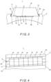
FIG. 3 is an illustrative diagram showing an enlarged view of one of permanent magnet units inFIG. 1 ; -
FIG. 4 is an illustrative diagram showing a preferable permanent magnet arrangement in the rotor according to the first embodiment; -
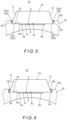
FIG. 5 is an illustrative diagram showing an enlarged view of a permanent magnet unit in a rotor according to a second embodiment; -
FIG. 6 is an illustrative diagram showing an enlarged view of a permanent magnet unit in a rotor according to a third embodiment; -
FIG. 7 is an illustrative diagram showing an enlarged view of a permanent magnet unit in a rotor according to a fourth embodiment; and -
FIG. 8 is an illustrative diagram showing an enlarged view of a permanent magnet unit in a rotor according to a fifth embodiment. - 0020 Hereinafter, specific embodiments of the present invention will be described with reference to the drawings.
- 0021
- First, a motor rotor according to a first embodiment of the present invention is described on the basis of
FIGS. 1 to 4 . As illustrated in these figures, therotor 1 according to this embodiment is constituted by atubular rotor yoke 2 andpermanent magnets 10. Therotor yoke 2 has an outer peripheral surface of a polygonal shape (in particular, an octagonal shape) and has an inner peripheral surface of a cylindrical shape. Thepermanent magnets 10 are bonded to surfaces (mounting surfaces) 2a of the outer periphery of therotor yoke 2. Note that the shape of therotor yoke 2 is not limited to an octagonal shape. Therotor yoke 2 may have a polygonal shape corresponding to the number ofpermanent magnets 10 to be provided thereon or may have an outer peripheral surface of a cylindrical shape that is similar to the inner peripheral surface. - 0022 The
rotor yoke 2 has amounting groove 3 as well as abonding groove 5 for an adhesive 6 in eachmounting surface 2a thereof. The mounting groove 3a is formed substantially along anaxis 2b of therotor yoke 2 and opened to twoend surfaces rotor yoke 2. Thebonding groove 5 is formed along themounting groove 3 in abottom surface 3c of themounting groove 3 and opened to the twoend surfaces rotor yoke 2. - 0023 Two
inner walls 3a and 3b of themounting groove 3 are formed as inclined surfaces tapering toward the open side opposite to thebottom surface 3c of themounting groove 3. Twoinner walls bonding groove 5 are formed as surfaces vertical to abottom surface 5c of thebonding groove 5. - 0024 Each
permanent magnet 10 is composed of a prismatic body having a trapezoidal cross section and the longest side (base) thereof is inserted in themounting groove 3. That is to say, twosides permanent magnet 10 opposed to the twoinner walls 3a and 3b of themounting groove 3 are formed as inclined surfaces tapering from the base side toward the opposite side of thepermanent magnet 10, and the base side of thepermanent magnet 10 is inserted in themounting groove 3. In onemounting groove 3, a plurality of (in this example, seven)permanent magnets 10 are inserted and mounted continuously with no gaps as shown inFIG. 4 . - 0025 A clearance enough for brazing is formed between each
inner wall 3a, 3b of the mountinggroove 3 and eachside permanent magnet 10 opposed thereto. However, the width of the opening of the mountinggroove 3 is smaller than the width of the base (bottom surface) of thepermanent magnet 10, so that engagement between the mountinggroove 3 and thepermanent magnet 10 inserted in the mountinggroove 3 prevents thepermanent magnet 10 from slipping out radially through the opening of the mountinggroove 3. - 0026 In the
rotor 1 according to this embodiment, abottom surface 13 of thepermanent magnet 10 is bonded to therotor yoke 2 by the adhesive 6 that is applied in thebonding groove 5. Further, eachinner wall 3a, 3b of the mountinggroove 3 and eachside permanent magnet 10 opposed thereto are bonded therebetween by brazing (by a brazing material 4). - 0027 The brazing may use, for example, a known laser brazing method. The brazing material may be, for example, a brazing wire (copper/
silicon 3% alloy). The adhesive 6 may be, for example, a epoxy resin adhesive or a silicone adhesive. - 0028 Note that it is preferred that, as shown in
FIG. 4 , the mountinggroove 3 and thebonding groove 5 are formed slightly obliquely with respect to the axis of therotor yoke 2 and thepermanent magnets 10 are also arranged slightly obliquely. This configuration prevents pulsation of therotor 1 as assembled in a motor. - 0029 In the
rotor 1 according to this embodiment having the above-described configuration, with the bonded side of thepermanent magnet 10 inserted in the mountinggroove 3 formed on therotor yoke 2, the twoinner walls 3a, 3b of the mountinggroove 3 and the twosides permanent magnet 10 opposed to the twoinner walls 3a, 3b are bonded by brazing, that is to say, bonded by the brazing material embedded between the twoinner walls 3a, 3b of the mountinggroove 3 and the twosides permanent magnet 10. Thus, the bonding surface where therotor yoke 2 and thepermanent magnet 10 are bonded to each other is increased as compared with that in the above-described conventional rotor, so that the bonding strength between therotor yoke 2 and thepermanent magnet 10 is increased. Consequently, as compared with the conventional rotor, therotor 1 effectively prevents thepermanent magnet 10 from coming off from therotor yoke 2, even when a strong centrifugal force generated by high-speed rotation of therotor 1 acts on thepermanent magnet 10. - 0030 Further, in the
rotor 1 according to this embodiment, the twoinner walls 3a, 3b of the mountinggroove 3 are formed as inclined surfaces tapering toward the open side opposite to thebottom surface 3c of the mountinggroove 3 and the twosides permanent magnet 10 opposed to the twoinner walls 3a, 3b of the mountinggroove 3 are also formed as inclined surfaces tapering from the base side toward the opposite side of thepermanent magnet 10. Therefore, thebrazing material 4 embedded between the twoinner walls 3a, 3b of the mountinggroove 3 and the twosides permanent magnet 10 through the brazing to uses not only its bonding force but also a mechanical acting force produced by the engagement between the mountinggroove 3 of therotor yoke 2 and thepermanent magnet 10 to restrain thepermanent magnet 10 from coming off outward from therotor yoke 2 due to a centrifugal force. Thus, therotor 1 according to this embodiment more effectively prevents coming-off of thepermanent magnet 10 from therotor yoke 2 than the conventional rotor. - 0031 Further, in the
rotor 1 according to this embodiment, the width of the opening of the mountinggroove 3 is smaller than the width of the base (bottom surface) of thepermanent magnet 10. Therefore, thepermanent magnet 10 inserted in the mountinggroove 3 is, by virtue of the engagement therebetween, structurally unable to slip out radially through the opening of the mountinggroove 3. Thus, therotor 1 according to this embodiment reliably prevents thepermanent magnet 10 from coming off from therotor yoke 2, even when a strong centrifugal force generated by high-speed rotation of therotor 1 acts on thepermanent magnet 10. - 0032 Furthermore, in the
rotor 1 according to this embodiment, thebottom surface 13 of thepermanent magnet 10 is bonded to therotor yoke 2 by the adhesive 6 applied in thebonding groove 5. Therefore, thepermanent magnet 10 is bonded to therotor yoke 2 not only by the bonding action of thebrazing material 4 but also by the adhesive 6. Thus, thepermanent magnet 10 is more firmly bonded to therotor yoke 2 by the combined bonding action of thebrazing material 4 andadhesive 6. - 0033
- Next, a
motor rotor 21 according to a second embodiment of the present invention is described on the basis ofFIG. 5 . Therotor 21 according to this embodiment has arotor yoke 22 having a mountinggroove 23 that differs in cross-sectional shape from that of therotor yoke 2 of therotor 1 according to the first embodiment. The other structures of therotor 21 are identical to those of therotor 1. - 0034 As illustrated in
FIG. 5 , the mountinggroove 23 has a shape in which twoinner walls inclined surfaces bottom surface 23c toward the opposite open side of the mountinggroove 23 and then formed as inclined surfaces (upperinclined surfaces groove 23. Thepermanent magnet 10 is inserted between the lowerinclined surfaces groove 23, and eachside permanent magnet 10 and each upperinclined surface groove 23 are brazed therebetween by abrazing material 24. - 0035 Note that the
permanent magnet 10 can be slid along the mountinggroove 23; however, no unnecessary gaps are formed between the lowerinclined surfaces groove 23 and the twosides permanent magnet 10. InFIG. 5 , thereference numeral 22a denotes a mounting surface on an outer peripheral surface of therotor yoke 22. - 0036 In the
rotor 21 having this configuration, the bonding force of thebrazing material 24 embedded between the upperinclined surfaces groove 23 and the twosides permanent magnet 10 prevents thepermanent magnet 10 from coming off outward from therotor yoke 21 and also prevents thepermanent magnet 10 from moving along the mountinggroove 23. Further, the engagement between the lowerinclined surfaces groove 23 and the twosides permanent magnet 10 structurally prevents thepermanent magnet 10 from coming off from therotor yoke 2. Thus, therotor 21 according to this embodiment reliably prevents thepermanent magnet 10 from coming off from therotor yoke 22. - 0037
- Next, a
motor rotor 31 according to a third embodiment of the present invention is described on the basis ofFIG. 6 . Therotor 31 according to this embodiment has arotor yoke 32 having a mountinggroove 33 that differs in cross-sectional shape from that of therotor yoke 2 of therotor 1 according to the first embodiment. The other structures of therotor 31 are identical to those of therotor 1. - 0038 As illustrated in
FIG. 6 , twoinner walls rotor yoke 32 in this embodiment are formed as surfaces vertical to abottom surface 33c of therotor yoke 32 similarly to those of thebonding groove 5. Eachside permanent magnet 10 and eachinner wall groove 33 are brazed therebetween by abrazing material 34. InFIG. 6 , thereference numeral 32a denotes a mounting surface on an outer peripheral surface of therotor yoke 32. - 0039 In the
rotor 31 having this configuration, the bonding surface where therotor yoke 32 and thepermanent magnet 10 are bonded to each other is increased as compared with the above-described conventional rotor, so that the bonding strength between therotor yoke 32 and thepermanent magnet 10 is increased. Consequently, as compared with the conventional rotor, therotor 31 effectively prevents thepermanent magnet 10 from coming off from therotor yoke 32, even when a strong centrifugal force generated by high-speed rotation of therotor 31 acts on thepermanent magnet 10. - 0040 Further, also in the
rotor 31 according to this embodiment, the twosides permanent magnet 10 opposed to the twoinner walls groove 33 are formed as inclined surfaces tapering from the base side toward the opposite side of thepermanent magnet 10. Therefore, thebrazing material 34 embedded between the twoinner walls groove 33 and the twosides permanent magnet 10 through the brazing uses not only its bonding force but also a mechanical acting force produced by the engagement between the mountinggroove 33 of therotor yoke 32 and thepermanent magnet 10 to restrain thepermanent magnet 10 from coming off outward from therotor yoke 32. Thus, therotor 31 according to this embodiment more effectively prevents coming-off of thepermanent magnet 10 from therotor yoke 32 than the conventional rotor. - 0041
- Next, a
motor rotor 41 according to a fourth embodiment of the present invention is described on the basis ofFIG. 7 . Therotor 41 according to this embodiment has apermanent magnet 45 that differs in cross-sectional shape from thepermanent magnet 10 of therotor 1 according to the first embodiment. The other structures of therotor 41 are identical to those of therotor 1. Specifically, as illustrated inFIG. 7 , thepermanent magnet 45 in this embodiment has a top having a convex curved surface. Thepermanent magnet 45 having this shape provides a high magnetic flux density. InFIG. 7 , thereference numerals permanent magnet 45 and thereference numeral 49 denotes a bottom surface of thepermanent magnet 45. - 0042
- Next, a
motor rotor 51 according to a fifth embodiment of the present invention is described on the basis ofFIG. 8 . Therotor 51 according to this embodiment has apermanent magnet 55 that differs in cross-sectional shape from thepermanent magnet 10 of therotor 31 according to the third embodiment. The other structures of therotor 51 are identical to those of therotor 1. Specifically, as illustrated inFIG. 8 , thepermanent magnet 55 in this embodiment has a rectangular cross section. Eachside permanent magnet 55 and eachinner wall groove 33 are brazed therebetween by thebrazing material 34. InFIG. 8 , thereference numeral 58 denotes a bottom surface of thepermanent magnet 55. - 0043 Also in the
rotor 51 having this configuration, the bonding surface where therotor yoke 32 and thepermanent magnet 55 are bonded to each other is increased as compared with the above-described conventional rotor, so that the bonding strength between therotor yoke 32 and thepermanent magnet 55 is increased. Consequently, as compared with the conventional rotor, therotor 51 effectively prevents thepermanent magnet 55 from coming off from therotor yoke 2, even when a strong centrifugal force generated by high-speed rotation of therotor 51 acts on thepermanent magnet 55. - 0044 Above have been described specific embodiments of the present invention. However, it should be noted that the present invention is not limited to the above-described embodiments and can be implemented in other manners.
- 0045 For example, in the first and fourth embodiments, the width of the opening of the mounting
groove 3 is set to be smaller than the width of the base (bottom surface) of thepermanent magnet rotor yoke 2 and thepermanent magnet groove 3 may be set to be larger than the width of the base (bottom surface) of thepermanent magnet - 0046 Further, in the first to fifth embodiments, seven
permanent magnets permanent magnets - 0047 Further, in the fifth embodiment, the mounting
groove 33 may be replaced by the mountinggroove 3 in the first and fourth embodiments. - 0048 As already mentioned above, the foregoing description of the embodiments is not limitative but illustrative in all aspects. One skilled in the art would be able to make variations and modifications as appropriate. The scope of the invention is not defined by the above-described embodiments, but is defined by the appended claims. Further, the scope of the invention encompasses all modifications made from the embodiments within a scope equivalent to the scope of the claims.
- 0049
- 1
- Rotor
- 2
- Rotor yoke
- 2a
- Mounting surface
- 2b
- Axis
- 2c, 2d
- End surface
- 3
- Mounting groove
- 3a, 3b
- Inner wall
- 4
- Brazing material
- 5
- Bonding groove
- 5a, 5b
- Inner wall
- 5c
- Bottom surface
- 6
- Adhesive
- 10
- Permanent magnet
- 11, 12
- Side
- 13
- Bottom surface
Claims (2)
- A motor rotor comprising:a rotor yoke; anda permanent magnet bonded to an outer peripheral surface of the rotor yoke, characterized in that:the rotor yoke has in the outer peripheral surface thereof a mounting groove formed to correspond to the permanent magnet and having the permanent magnet inserted therein;two sides of the permanent magnet opposed to two inner walls of the mounting groove are formed as inclined surfaces tapering from a bottom surface side toward an opposite side of the permanent magnet;the two inner walls of the mounting groove opposed to the two sides of the permanent magnet are formed as tapered inclined surfaces tapering from a bottom surface toward an open side of the mounting groove and widened inclined surfaces widening continuously from the tapered inclined surfaces to an opening of the mounting groove; andthe widened inclined surfaces of the mounting groove and the two sides of the permanent magnet opposed to the widened inclined surfaces are bonded by brazing with the inclined surfaces of the permanent magnet inserted between the tapered inclined surfaces of the mounting groove.
- The motor rotor according to claim 1, characterized in that a bottom surface of the permanent magnet is bonded with an adhesive to the bottom surface of the mounting groove.
Applications Claiming Priority (2)
| Application Number | Priority Date | Filing Date | Title |
|---|---|---|---|
| JP2021096269A JP7022860B1 (en) | 2021-06-09 | 2021-06-09 | Rotor for motor |
| PCT/JP2022/013474 WO2022259695A1 (en) | 2021-06-09 | 2022-03-23 | Motor rotor |
Publications (2)
| Publication Number | Publication Date |
|---|---|
| EP4354708A1 true EP4354708A1 (en) | 2024-04-17 |
| EP4354708A4 EP4354708A4 (en) | 2025-04-23 |
Family
ID=81073875
Family Applications (1)
| Application Number | Title | Priority Date | Filing Date |
|---|---|---|---|
| EP22819885.9A Withdrawn EP4354708A4 (en) | 2021-06-09 | 2022-03-23 | MOTOR ROTOR |
Country Status (5)
| Country | Link |
|---|---|
| US (1) | US20240283311A1 (en) |
| EP (1) | EP4354708A4 (en) |
| JP (1) | JP7022860B1 (en) |
| CN (1) | CN117501592A (en) |
| WO (1) | WO2022259695A1 (en) |
Families Citing this family (1)
| Publication number | Priority date | Publication date | Assignee | Title |
|---|---|---|---|---|
| DE102023128587A1 (en) * | 2023-10-18 | 2025-04-24 | Rolls-Royce Deutschland Ltd & Co Kg | Assembly for a machine |
Family Cites Families (7)
| Publication number | Priority date | Publication date | Assignee | Title |
|---|---|---|---|---|
| JPS5734178U (en) * | 1980-07-31 | 1982-02-23 | ||
| JPH05161287A (en) * | 1991-11-29 | 1993-06-25 | Fanuc Ltd | Rotor of synchronous apparatus |
| JPH07312837A (en) * | 1994-03-25 | 1995-11-28 | Meidensha Corp | Rotor for permanent magnet motor |
| JP3599132B2 (en) * | 1995-07-14 | 2004-12-08 | 本田技研工業株式会社 | Method of manufacturing rotor for rotating machine and permanent magnet fixing device for manufacturing rotor of rotating machine |
| JP2005318765A (en) | 2004-04-30 | 2005-11-10 | Mitsui High Tec Inc | Rotor core and rotor |
| US9057271B2 (en) * | 2011-11-04 | 2015-06-16 | Siemens Energy, Inc. | Splice insert repair for superalloy turbine blades |
| DE102013220562B4 (en) | 2013-10-11 | 2024-12-19 | Robert Bosch Gmbh | Assembly for an electrical machine, method for producing an assembly and electrical machine with an assembly |
-
2021
- 2021-06-09 JP JP2021096269A patent/JP7022860B1/en not_active Expired - Fee Related
-
2022
- 2022-03-23 CN CN202280040527.XA patent/CN117501592A/en active Pending
- 2022-03-23 WO PCT/JP2022/013474 patent/WO2022259695A1/en not_active Ceased
- 2022-03-23 US US18/568,175 patent/US20240283311A1/en active Pending
- 2022-03-23 EP EP22819885.9A patent/EP4354708A4/en not_active Withdrawn
Also Published As
| Publication number | Publication date |
|---|---|
| WO2022259695A1 (en) | 2022-12-15 |
| JP7022860B1 (en) | 2022-02-18 |
| US20240283311A1 (en) | 2024-08-22 |
| CN117501592A (en) | 2024-02-02 |
| JP2022188331A (en) | 2022-12-21 |
| EP4354708A4 (en) | 2025-04-23 |
Similar Documents
| Publication | Publication Date | Title |
|---|---|---|
| US6548932B1 (en) | Nonmagnetic magnet retention channel arrangement for high speed rotors | |
| US4302693A (en) | Wedge shaped permanent magnet rotor assembly with magnet cushions | |
| US11936240B2 (en) | Stator for an axial flux machine | |
| CN1933297B (en) | Electric rotating machine | |
| US6492754B1 (en) | Magnet retention channel arrangement for high speed operation | |
| CN104106199B (en) | rotating electrical machine | |
| RU2610300C2 (en) | Rotor of electric motor with permanent magnets | |
| JP6836842B2 (en) | Rotor and motor including it | |
| JP4735980B2 (en) | AC generator for vehicle and method for manufacturing the same | |
| CN105122596A (en) | Individual-segment rotor having individual segments retained by flexural supports | |
| US20240283311A1 (en) | Motor rotor | |
| US20130033137A1 (en) | Spindle motor | |
| CN101128969B (en) | Magnetic body, rotor, and motor | |
| US20120043842A1 (en) | Hydrodynamic bearing assembly and motor including the same | |
| CN212486216U (en) | Stator and motor having the same | |
| CN104981967B (en) | Rotating electric machine including integrated permanent magnets | |
| JP2002502213A (en) | Rotor for electronic commutation motor and improved method for mass production thereof | |
| CN106575893A (en) | Permanent magnet embedded electric motor and compressor | |
| JP2013126311A (en) | Rotary electric machine | |
| JP5360224B2 (en) | Method for manufacturing electric motor rotor | |
| US9281721B2 (en) | Permanent-magnet electric motor comprising a segmented stator | |
| CN106063085B (en) | Rotor | |
| CN100428608C (en) | flat motor | |
| KR102170645B1 (en) | Rotor of motor and motor including the same | |
| WO2017203877A1 (en) | Rotating electric machine |
Legal Events
| Date | Code | Title | Description |
|---|---|---|---|
| STAA | Information on the status of an ep patent application or granted ep patent |
Free format text: STATUS: THE INTERNATIONAL PUBLICATION HAS BEEN MADE |
|
| PUAI | Public reference made under article 153(3) epc to a published international application that has entered the european phase |
Free format text: ORIGINAL CODE: 0009012 |
|
| STAA | Information on the status of an ep patent application or granted ep patent |
Free format text: STATUS: REQUEST FOR EXAMINATION WAS MADE |
|
| 17P | Request for examination filed |
Effective date: 20231219 |
|
| AK | Designated contracting states |
Kind code of ref document: A1 Designated state(s): AL AT BE BG CH CY CZ DE DK EE ES FI FR GB GR HR HU IE IS IT LI LT LU LV MC MK MT NL NO PL PT RO RS SE SI SK SM TR |
|
| DAV | Request for validation of the european patent (deleted) | ||
| DAX | Request for extension of the european patent (deleted) | ||
| A4 | Supplementary search report drawn up and despatched |
Effective date: 20250320 |
|
| RIC1 | Information provided on ipc code assigned before grant |
Ipc: H02K 1/278 20220101AFI20250314BHEP |
|
| STAA | Information on the status of an ep patent application or granted ep patent |
Free format text: STATUS: THE APPLICATION IS DEEMED TO BE WITHDRAWN |
|
| 18D | Application deemed to be withdrawn |
Effective date: 20251001 |