EP4354637A1 - Battery cell, battery, and electric device - Google Patents
Battery cell, battery, and electric device Download PDFInfo
- Publication number
- EP4354637A1 EP4354637A1 EP21960937.7A EP21960937A EP4354637A1 EP 4354637 A1 EP4354637 A1 EP 4354637A1 EP 21960937 A EP21960937 A EP 21960937A EP 4354637 A1 EP4354637 A1 EP 4354637A1
- Authority
- EP
- European Patent Office
- Prior art keywords
- electrode plate
- weld
- winding
- battery cell
- current collection
- Prior art date
- Legal status (The legal status is an assumption and is not a legal conclusion. Google has not performed a legal analysis and makes no representation as to the accuracy of the status listed.)
- Pending
Links
- 238000004804 winding Methods 0.000 claims abstract description 240
- 238000009826 distribution Methods 0.000 abstract description 21
- 238000005476 soldering Methods 0.000 abstract 11
- 238000003466 welding Methods 0.000 description 41
- 238000010586 diagram Methods 0.000 description 28
- 239000000243 solution Substances 0.000 description 20
- 230000004308 accommodation Effects 0.000 description 8
- 239000007773 negative electrode material Substances 0.000 description 8
- 239000007774 positive electrode material Substances 0.000 description 8
- 238000012360 testing method Methods 0.000 description 7
- 239000011149 active material Substances 0.000 description 4
- 238000005516 engineering process Methods 0.000 description 4
- VNWKTOKETHGBQD-UHFFFAOYSA-N methane Chemical compound C VNWKTOKETHGBQD-UHFFFAOYSA-N 0.000 description 4
- 230000000712 assembly Effects 0.000 description 3
- 238000000429 assembly Methods 0.000 description 3
- 230000010349 pulsation Effects 0.000 description 3
- 238000007789 sealing Methods 0.000 description 3
- RYGMFSIKBFXOCR-UHFFFAOYSA-N Copper Chemical compound [Cu] RYGMFSIKBFXOCR-UHFFFAOYSA-N 0.000 description 2
- 206010016322 Feeling abnormal Diseases 0.000 description 2
- XEEYBQQBJWHFJM-UHFFFAOYSA-N Iron Chemical compound [Fe] XEEYBQQBJWHFJM-UHFFFAOYSA-N 0.000 description 2
- 229910052782 aluminium Inorganic materials 0.000 description 2
- XAGFODPZIPBFFR-UHFFFAOYSA-N aluminium Chemical compound [Al] XAGFODPZIPBFFR-UHFFFAOYSA-N 0.000 description 2
- 229910052802 copper Inorganic materials 0.000 description 2
- 239000010949 copper Substances 0.000 description 2
- 239000008151 electrolyte solution Substances 0.000 description 2
- 238000012986 modification Methods 0.000 description 2
- 230000004048 modification Effects 0.000 description 2
- 239000003345 natural gas Substances 0.000 description 2
- 229910000838 Al alloy Inorganic materials 0.000 description 1
- OKTJSMMVPCPJKN-UHFFFAOYSA-N Carbon Chemical compound [C] OKTJSMMVPCPJKN-UHFFFAOYSA-N 0.000 description 1
- WHXSMMKQMYFTQS-UHFFFAOYSA-N Lithium Chemical compound [Li] WHXSMMKQMYFTQS-UHFFFAOYSA-N 0.000 description 1
- HBBGRARXTFLTSG-UHFFFAOYSA-N Lithium ion Chemical compound [Li+] HBBGRARXTFLTSG-UHFFFAOYSA-N 0.000 description 1
- 229910052799 carbon Inorganic materials 0.000 description 1
- 238000005520 cutting process Methods 0.000 description 1
- 238000011161 development Methods 0.000 description 1
- 239000003792 electrolyte Substances 0.000 description 1
- 238000004146 energy storage Methods 0.000 description 1
- ZZUFCTLCJUWOSV-UHFFFAOYSA-N furosemide Chemical compound C1=C(Cl)C(S(=O)(=O)N)=CC(C(O)=O)=C1NCC1=CC=CO1 ZZUFCTLCJUWOSV-UHFFFAOYSA-N 0.000 description 1
- 229910052742 iron Inorganic materials 0.000 description 1
- 229910052744 lithium Inorganic materials 0.000 description 1
- 229910000625 lithium cobalt oxide Inorganic materials 0.000 description 1
- 229910001416 lithium ion Inorganic materials 0.000 description 1
- GELKBWJHTRAYNV-UHFFFAOYSA-K lithium iron phosphate Chemical compound [Li+].[Fe+2].[O-]P([O-])([O-])=O GELKBWJHTRAYNV-UHFFFAOYSA-K 0.000 description 1
- 229910002102 lithium manganese oxide Inorganic materials 0.000 description 1
- BFZPBUKRYWOWDV-UHFFFAOYSA-N lithium;oxido(oxo)cobalt Chemical compound [Li+].[O-][Co]=O BFZPBUKRYWOWDV-UHFFFAOYSA-N 0.000 description 1
- VLXXBCXTUVRROQ-UHFFFAOYSA-N lithium;oxido-oxo-(oxomanganiooxy)manganese Chemical compound [Li+].[O-][Mn](=O)O[Mn]=O VLXXBCXTUVRROQ-UHFFFAOYSA-N 0.000 description 1
- 239000000463 material Substances 0.000 description 1
- 229910052751 metal Inorganic materials 0.000 description 1
- 239000002184 metal Substances 0.000 description 1
- 238000000034 method Methods 0.000 description 1
- 239000003921 oil Substances 0.000 description 1
- 230000010287 polarization Effects 0.000 description 1
- 238000011160 research Methods 0.000 description 1
- 239000000565 sealant Substances 0.000 description 1
- 229910052710 silicon Inorganic materials 0.000 description 1
- 239000010703 silicon Substances 0.000 description 1
- 239000010935 stainless steel Substances 0.000 description 1
- 229910001256 stainless steel alloy Inorganic materials 0.000 description 1
- 238000012795 verification Methods 0.000 description 1
Images




Classifications
-
- H—ELECTRICITY
- H01—ELECTRIC ELEMENTS
- H01M—PROCESSES OR MEANS, e.g. BATTERIES, FOR THE DIRECT CONVERSION OF CHEMICAL ENERGY INTO ELECTRICAL ENERGY
- H01M50/00—Constructional details or processes of manufacture of the non-active parts of electrochemical cells other than fuel cells, e.g. hybrid cells
- H01M50/50—Current conducting connections for cells or batteries
- H01M50/531—Electrode connections inside a battery casing
- H01M50/536—Electrode connections inside a battery casing characterised by the method of fixing the leads to the electrodes, e.g. by welding
-
- H—ELECTRICITY
- H01—ELECTRIC ELEMENTS
- H01M—PROCESSES OR MEANS, e.g. BATTERIES, FOR THE DIRECT CONVERSION OF CHEMICAL ENERGY INTO ELECTRICAL ENERGY
- H01M50/00—Constructional details or processes of manufacture of the non-active parts of electrochemical cells other than fuel cells, e.g. hybrid cells
- H01M50/50—Current conducting connections for cells or batteries
- H01M50/531—Electrode connections inside a battery casing
-
- H—ELECTRICITY
- H01—ELECTRIC ELEMENTS
- H01M—PROCESSES OR MEANS, e.g. BATTERIES, FOR THE DIRECT CONVERSION OF CHEMICAL ENERGY INTO ELECTRICAL ENERGY
- H01M10/00—Secondary cells; Manufacture thereof
- H01M10/04—Construction or manufacture in general
-
- H—ELECTRICITY
- H01—ELECTRIC ELEMENTS
- H01M—PROCESSES OR MEANS, e.g. BATTERIES, FOR THE DIRECT CONVERSION OF CHEMICAL ENERGY INTO ELECTRICAL ENERGY
- H01M10/00—Secondary cells; Manufacture thereof
- H01M10/04—Construction or manufacture in general
- H01M10/0431—Cells with wound or folded electrodes
-
- H—ELECTRICITY
- H01—ELECTRIC ELEMENTS
- H01M—PROCESSES OR MEANS, e.g. BATTERIES, FOR THE DIRECT CONVERSION OF CHEMICAL ENERGY INTO ELECTRICAL ENERGY
- H01M10/00—Secondary cells; Manufacture thereof
- H01M10/05—Accumulators with non-aqueous electrolyte
- H01M10/058—Construction or manufacture
- H01M10/0587—Construction or manufacture of accumulators having only wound construction elements, i.e. wound positive electrodes, wound negative electrodes and wound separators
-
- H—ELECTRICITY
- H01—ELECTRIC ELEMENTS
- H01M—PROCESSES OR MEANS, e.g. BATTERIES, FOR THE DIRECT CONVERSION OF CHEMICAL ENERGY INTO ELECTRICAL ENERGY
- H01M50/00—Constructional details or processes of manufacture of the non-active parts of electrochemical cells other than fuel cells, e.g. hybrid cells
- H01M50/10—Primary casings; Jackets or wrappings
- H01M50/102—Primary casings; Jackets or wrappings characterised by their shape or physical structure
- H01M50/107—Primary casings; Jackets or wrappings characterised by their shape or physical structure having curved cross-section, e.g. round or elliptic
-
- H—ELECTRICITY
- H01—ELECTRIC ELEMENTS
- H01M—PROCESSES OR MEANS, e.g. BATTERIES, FOR THE DIRECT CONVERSION OF CHEMICAL ENERGY INTO ELECTRICAL ENERGY
- H01M50/00—Constructional details or processes of manufacture of the non-active parts of electrochemical cells other than fuel cells, e.g. hybrid cells
- H01M50/10—Primary casings; Jackets or wrappings
- H01M50/147—Lids or covers
- H01M50/148—Lids or covers characterised by their shape
- H01M50/152—Lids or covers characterised by their shape for cells having curved cross-section, e.g. round or elliptic
-
- H—ELECTRICITY
- H01—ELECTRIC ELEMENTS
- H01M—PROCESSES OR MEANS, e.g. BATTERIES, FOR THE DIRECT CONVERSION OF CHEMICAL ENERGY INTO ELECTRICAL ENERGY
- H01M50/00—Constructional details or processes of manufacture of the non-active parts of electrochemical cells other than fuel cells, e.g. hybrid cells
- H01M50/50—Current conducting connections for cells or batteries
- H01M50/531—Electrode connections inside a battery casing
- H01M50/538—Connection of several leads or tabs of wound or folded electrode stacks
-
- H—ELECTRICITY
- H01—ELECTRIC ELEMENTS
- H01M—PROCESSES OR MEANS, e.g. BATTERIES, FOR THE DIRECT CONVERSION OF CHEMICAL ENERGY INTO ELECTRICAL ENERGY
- H01M50/00—Constructional details or processes of manufacture of the non-active parts of electrochemical cells other than fuel cells, e.g. hybrid cells
- H01M50/50—Current conducting connections for cells or batteries
- H01M50/543—Terminals
- H01M50/547—Terminals characterised by the disposition of the terminals on the cells
- H01M50/548—Terminals characterised by the disposition of the terminals on the cells on opposite sides of the cell
-
- Y—GENERAL TAGGING OF NEW TECHNOLOGICAL DEVELOPMENTS; GENERAL TAGGING OF CROSS-SECTIONAL TECHNOLOGIES SPANNING OVER SEVERAL SECTIONS OF THE IPC; TECHNICAL SUBJECTS COVERED BY FORMER USPC CROSS-REFERENCE ART COLLECTIONS [XRACs] AND DIGESTS
- Y02—TECHNOLOGIES OR APPLICATIONS FOR MITIGATION OR ADAPTATION AGAINST CLIMATE CHANGE
- Y02E—REDUCTION OF GREENHOUSE GAS [GHG] EMISSIONS, RELATED TO ENERGY GENERATION, TRANSMISSION OR DISTRIBUTION
- Y02E60/00—Enabling technologies; Technologies with a potential or indirect contribution to GHG emissions mitigation
- Y02E60/10—Energy storage using batteries
-
- Y—GENERAL TAGGING OF NEW TECHNOLOGICAL DEVELOPMENTS; GENERAL TAGGING OF CROSS-SECTIONAL TECHNOLOGIES SPANNING OVER SEVERAL SECTIONS OF THE IPC; TECHNICAL SUBJECTS COVERED BY FORMER USPC CROSS-REFERENCE ART COLLECTIONS [XRACs] AND DIGESTS
- Y02—TECHNOLOGIES OR APPLICATIONS FOR MITIGATION OR ADAPTATION AGAINST CLIMATE CHANGE
- Y02P—CLIMATE CHANGE MITIGATION TECHNOLOGIES IN THE PRODUCTION OR PROCESSING OF GOODS
- Y02P70/00—Climate change mitigation technologies in the production process for final industrial or consumer products
- Y02P70/50—Manufacturing or production processes characterised by the final manufactured product
Definitions
- This application relates to the technical field of batteries, and in particular, to a battery cell, a battery, and an electrical device.
- Batteries are widely used in electronic devices such as a mobile phone, a notebook computer, an electric power cart, an electric vehicle, an electric airplane, an electric ship, an electric toy car, an electric toy ship, an electric toy airplane, and an electric tool.
- Some embodiments of this application provide a battery cell, a battery, and an electrical device to enhance power performance of the battery.
- an embodiment of this application provides a battery cell, including an electrode assembly.
- the electrode assembly includes a first electrode plate.
- a plurality of weld portions are disposed on one side of the first electrode plate along a width direction, and the plurality of weld portions are spaced apart along a length direction of the first electrode plate.
- the electrode assembly has a jelly-roll structure.
- the first electrode plate includes a winding start end and a winding termination end. A weld portion closest to the winding start end among the plurality of weld portions is a first weld portion. A weld portion closest to the winding termination end among the plurality of weld portions is a second weld portion.
- the first electrode plate includes a body section. The body section is from an edge of the first weld portion to an edge of the second weld portion, the edge of the first weld portion being close to the winding start end, and the edge of the second weld portion being close to the winding termination end.
- the body section is equally divided into a plurality of subsections, each subsection being L in length. A total length of the weld portions of each subsection is not less than 5% ⁇ L, where 200 mm ⁇ L ⁇ 1200 mm.
- the current collection component is welded to the electrode assembly by continuous linear laser welding or pulsation welding, leaving weld marks to be X-shaped, ring-shaped, or the like.
- weld marks As can be seen from an unwound electrode plate, along a length direction of the electrode plate, the weld portions in some sections are relatively dense, the weld portions in other sections are relatively sparse, and the distribution of the weld portions on the electrode plate is nonuniform.
- an effective welding length of the electrode plate that is, a total length of the weld portions of the section) is not enough to match the length of the electrode plate.
- the flow capacity of electrical current between the electrode plate and the current collection component is low, and the internal resistance of the battery cell is high, thereby impairing the power performance of the battery cell.
- a plurality of spaced-out weld portions are formed in the length direction of the first electrode plate.
- the body portion defined by the first weld portion and the second weld portion on the first electrode plate is divided into a plurality of subsections of equal length along the length direction of the first electrode plate, the first weld portion being close to the winding start end, and the second weld portion being close to the winding termination end.
- a total length of the weld portions of each subsection is not less than 5% of the length of the subsection. In this way, the distribution of the weld portions formed by the welding between the first electrode plate and the current collection component is more reasonable, thereby reducing the internal resistance of the battery cell, satisfying the practical flow capacity requirement, and in turn, improving the power performance of the battery cell.
- the length of the subsection ranges from 200 mm to 1200 mm, thereby making the winding length of the first electrode plate meet practical product requirements and achieving a relatively high energy density of the battery cell.
- an absolute value of a difference of the total length of the weld portions between any two subsections is less than or equal to 10 mm.
- the total length of the weld portions is identical between any two subsections.
- an absolute value of a difference of a number of the weld portions between any two subsections is less than or equal to 10.
- the number of the weld portions is identical between any two subsections.
- the first electrode plate further includes a winding start section contiguous to the body section.
- the winding start section is from the winding start end to the edge of the first weld portion, the edge being close to the winding start end.
- the winding start section is from the winding start end to the edge of the first weld portion, the edge being close to the winding start end.
- the winding start end and the edge of the first weld portion define the winding start section, the edge of the first weld portion being close to the winding start end.
- No weld portion is formed on the winding start section, so that there is no welding relationship between the winding start section and the current collection component, thereby facilitating the welding between the current collection component and the electrode terminal to output electrical energy of the battery cell.
- the winding start section is A in length, satisfying A ⁇ L.
- the distance between the winding start end and the first weld portion is less than a length of a characteristic section.
- the length of the winding start section without a weld portion is less than the length of a subsection with a weld portion, thereby preventing the section without a weld portion on the first electrode plate from being excessively long, and ensuring stable output of electrical energy of the battery cell.
- the first electrode plate further includes a winding termination section contiguous to the body section.
- the winding termination section is from the winding termination end to the edge of the second weld portion, the edge being close to the winding termination end.
- the winding termination section is from the winding termination end to the edge of the second weld portion, the edge being close to the winding termination end.
- the winding termination end and the edge of the second weld portion define the winding termination section, the edge of the second weld portion being close to the winding termination end.
- No weld portion is formed on the winding termination section.
- the winding termination section is B in length, satisfying B ⁇ L.
- the length of the winding termination section is less than the length of the subsection.
- the length of the winding start section without a weld portion is less than the length of a subsection with a weld portion, thereby preventing the section without a weld portion on the first electrode plate from being excessively long, and ensuring stable output of electrical energy of the battery cell.
- a number of the weld portions of a circle close to a winding center of the electrode assembly is less than a number of the weld portions of a circle away from the winding center.
- the length of the circle close to the winding center is less than the length of the circle away from the winding center.
- the number of weld portions formed on the circle close to the winding center of the jelly-roll type electrode assembly is smaller than the number of weld portions formed on the circle away from the winding center.
- the battery cell further includes a housing, an end cap assembly, and a current collection component.
- the housing is configured to accommodate the electrode assembly.
- the housing includes an opening.
- the end cap assembly includes an end cap and electrode terminals.
- the end cap is configured to cover the opening.
- Each electrode terminal is mounted on the end cap.
- the current collection component is located between the end cap and the electrode assembly, and configured to connect a tab portion of the electrode assembly to the electrode terminal.
- the tab portion is formed by winding an uncoated portion of the first electrode plate. At least a part of the current collection component is welded to the tab portion to form the plurality of weld portions.
- At least a part of the current collection component is welded to the tab portion to form a plurality of weld portions.
- the body portion defined by the first weld portion and the second weld portion on the first electrode plate is divided into a plurality of subsections of equal length along the length direction of the first electrode plate, the first weld portion being close to the winding start end, and the second weld portion being close to the winding termination end.
- a total length of the weld portions of each subsection is not less than 5% of the length of the subsection. In this way, the distribution of the weld portions formed by the welding between the first electrode plate and the current collection component is more reasonable, thereby reducing the internal resistance of the battery cell, satisfying the practical flow capacity requirement, and in turn, improving the power performance of the battery cell.
- the first electrode plate further includes a winding start section from the winding start end to the edge of the first weld portion, the edge being close to the winding start end.
- the uncoated region of the body section is wound to form a first part
- the uncoated region of the winding start section is wound to form a second part
- the second part is located inside the first part along a radial direction.
- the current collection component includes a first current collection portion and a second current collection portion arranged continuously along the radial direction.
- the first current collection portion is arranged opposite to the first part along the width direction of the first electrode plate and is welded to the first part to form the plurality of weld portions.
- the second current collection portion is arranged opposite to the second part along the width direction of the first electrode plate and is welded to the electrode terminal.
- the uncoated region of the body section is wound to form the first part welded to the first current collection portion of the current collection component, thereby implementing electrical connection between the electrode assembly and the current collection component.
- the winding start section is from the winding start end to the edge of the first weld portion, the edge being close to the winding start end.
- the winding start end and the edge of the first weld portion define the winding start section, the edge of the first weld portion being close to the winding start end.
- No weld portion is formed on the winding start section, so that there is no welding relationship between the second part and the current collection component, the second part being formed by winding the uncoated region of the winding start section.
- No weld marks are formed on the second current collection portion opposite to the second part, thereby making it convenient to weld the current collection component to the electrode terminal through the second current collection portion to output electrical energy of the battery cell.
- the first electrode plate further includes a winding termination section from the winding termination end to the edge of the second weld portion, the edge being close to the winding termination end.
- the uncoated region of the body section is wound to form a first part
- the uncoated region of the winding termination section is wound to form a third part
- the third part is located outside the first part along a radial direction.
- the current collection component includes a first current collection portion and a third current collection portion arranged continuously along the radial direction.
- the first current collection portion is arranged opposite to the first part along the width direction of the first electrode plate and is welded to the first part to form the plurality of weld portions.
- the third current collection portion is arranged opposite to the third part along the width direction of the first electrode plate and is welded to the electrode terminal.
- the uncoated region of the body section is wound to form the first part welded to the first current collection portion of the current collection component, thereby implementing electrical connection between the electrode assembly and the current collection component.
- the winding termination section is from the winding termination end to the edge of the second weld portion, the edge being close to the winding termination end.
- the winding termination end and the edge of the second weld portion define the winding termination section, the edge of the second weld portion being close to the winding termination end.
- No weld portion is formed on the winding termination section, so that there is no welding relationship between the third part and the current collection component, the third part being formed by winding the uncoated region of the winding termination section. Therefore, no weld marks are formed on the third current collection portion opposite to the third part, thereby making it convenient to weld the current collection component to the electrode terminal through the third current collection portion to output electrical energy of the battery cell.
- an embodiment of this application provides a battery, including the battery according to any embodiment according to the first aspect.
- a battery containing the battery cell disclosed in an embodiment in the first aspect of this application is provided.
- the body portion defined by the first weld portion and the second weld portion on the first electrode plate of the battery cell is divided into a plurality of subsections of equal length, the first weld portion being close to the winding start end, and the second weld portion being close to the winding termination end.
- a total length of the weld portions of each subsection is not less than 5% of the length of the subsection. In this way, the distribution of the weld portions formed by the welding between the first electrode plate and the current collection component is more reasonable, thereby reducing the internal resistance of the battery cell, satisfying the practical flow capacity requirement, and in turn, improving the power performance of the battery.
- an embodiment of this application provides an electrical device, including the battery according to any embodiment in the second aspect of this application.
- the electrical device employs the battery provided by an embodiment in the second aspect of this application.
- the body portion defined by the first weld portion and the second weld portion on the first electrode plate of the battery cell is divided into a plurality of subsections of equal length, the first weld portion being close to the winding start end, and the second weld portion being close to the winding termination end.
- a total length of the weld portions of each subsection is not less than 5% of the length of the subsection. In this way, the distribution of the weld portions formed by the welding between the first electrode plate and the current collection component is more reasonable, thereby reducing the internal resistance of the battery, satisfying the practical flow capacity requirement, and in turn, improving the power performance of the battery.
- an indicated direction or positional relationship is a direction or positional relationship based on illustration in the drawings, or a direction or positional relationship by which a product in use according to this application is usually placed, or a direction or positional relationship commonly understood by a person skilled in the art, and is merely intended for ease or brevity of describing this application, but does not indicate or imply that the indicated apparatus or component is necessarily located in the specified direction or constructed or operated in the specified direction. Therefore, the indicated direction or positional relationship is never to be understood as a limitation on this application.
- the terms “first”, “second”, and “third” are merely intended for distinct description, but not intended to indicate or imply order of precedence.
- Power batteries are not only used in energy storage power systems such as hydro, thermal, wind, and solar power stations, but also widely used in electric means of transport such as electric bicycles, electric motorcycles, and electric vehicles, and used in many other fields such as military equipment and aerospace.
- the market demand for power batteries keeps soaring with the increase of the application fields of the power batteries.
- a battery cell includes a housing, an end cap assembly, and an electrode assembly.
- the end cap assembly fits and covers the housing to provide a hermetically sealed space for the electrode assembly and an electrolytic solution. Electrical energy of the electrode assembly may be output out of the housing through electrode terminals on the end cap assembly.
- the electrode assembly is welded to the current collection component through a tab.
- An electrode terminal is electrically connected to the current collection component to output electrical energy of the battery.
- the electrode assembly includes an electrode plate.
- the electrode plate includes a coated region coated with an active material layer and an uncoated region not coated with the active material layer. The uncoated region of the electrode plate is wound to form a tab portion.
- the current collection component is welded to the tab portion to form a plurality of weld portions.
- the tab For a jelly-roll all-tab electrode assembly, the tab needs to be flattened before being welded to the current collection component.
- the current collection component is welded to the electrode assembly by continuous linear laser welding or pulsation welding, leaving weld marks to be X-shaped, ring-shaped, or the like.
- weld portions in some sections are relatively dense, the weld portions in other sections are relatively sparse, and the distribution of the weld portions on the electrode plate is nonuniform.
- an effective welding length of the electrode plate (that is, a total length of the weld portions of the section) is not enough to match the length of the electrode plate. Consequently, the flow capacity of electrical current between the electrode plate and the current collection component is low, and the internal resistance of the battery cell is high, thereby impairing the power performance of the battery cell.
- a battery cell after in-depth research.
- a body portion defined by a first weld portion and a second weld portion on a first electrode plate is divided into a plurality of subsections of equal length, the first weld portion being close to a winding start end, and the second weld portion being close to the winding termination end.
- a total length of the weld portions of each subsection is not less than 5% of the length of the subsection.
- the electrical device may be a vehicle, a mobile phone, a portable device, a notebook computer, a ship, a spacecraft, an electric toy, a power tool, or the like.
- the vehicle may be an oil-fueled vehicle, a natural gas vehicle, or a new energy vehicle.
- the new energy vehicle may be a battery electric vehicle, a hybrid electric vehicle, a range-extended electric vehicle, or the like.
- the spacecraft includes an airplane, a rocket, a space shuttle, a spaceship, and the like.
- the electric toy includes a fixed or mobile electric toy, such as a game console, an electric car toy, an electric ship toy, an electric airplane toy, and the like.
- the power tool includes an electrical metal cutting tool, an electrical grinding tool, an electrical assembling tool, and a power tool for use in railways.
- Examples of the power tool are an electrical drill, an electrical grinder, an electrical wrench, an electrical screwdriver, an electrical hammer, an electrical impact drill, a concrete vibrator, an electrical planer, and the like.
- the electrical device is not particularly limited in this embodiment of this application.
- a vehicle is used as an example of the electrical device.
- FIG. 1 is a schematic structural diagram of a vehicle 1000 according to some embodiments of this application.
- a battery 100 is disposed inside the vehicle 1000.
- the battery 100 may be disposed at the bottom, front, or rear of the vehicle 1000.
- the battery 100 may be configured to supply power to the vehicle 1000.
- the battery 100 may serve as an operating power supply of the vehicle 1000.
- the vehicle 1000 may further include a controller 200 and a motor 300.
- the controller 200 is configured to control the battery 100 to supply power to the motor 300, for example, to meet electrical energy requirements in starting, navigating, or running the vehicle 1000.
- the battery 100 serves not only as an operating power supply of the vehicle 1000, but may also serve as a drive power supply of the vehicle 1000 to provide driving power for the vehicle 1000 in place of or partly in place of oil or natural gas.
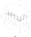
- FIG. 2 is a schematic structural diagram of a battery 100 according to some embodiments of this application.
- the battery 100 includes a box 10 and a battery cell 20.
- the battery cell 20 is accommodated in the box 10.
- the box 10 is configured to provide an accommodation space 11 for the battery cell 20.
- the box 10 may include a first part 12 and a second part 13.
- the first part 12 and the second part 13 fit and cover each other to define the accommodation space 11 configured to accommodate the battery cell 20.
- a junction between the first part 12 and the second part 13 may be sealed by a sealing element (not shown in the drawing).
- the sealing element may be a sealing ring, a sealant, or the like.
- the first part 12 and the second part 13 may be in various shapes, such as a cuboid or cylinder.
- the first part 12 is a hollow structure opened up at one end, in which an accommodation portion configured to accommodate the battery cell 20 is formed.
- the second part 13 may also be a hollow structure opened up at one side, in which an accommodation portion configured to accommodate the battery cell 20 is formed.
- the open-up side of the second part 13 fits and covers the open-up side of the first part 12 to form a box 10 that includes a hermetically sealed space.
- the first part 12 is a hollow structure opened up at one end, in which an accommodation portion configured to accommodate the battery cell 20 is formed
- the second part 13 is a plate-shaped structure.
- the second part 13 fits and covers the open-up side of the first part 12 to form the box 10 that includes a hermetically sealed space.
- the plurality of battery cells 20 may be connected in series, parallel, or series-and-parallel pattern.
- the series-and-parallel pattern means a combination of series connection and parallel connection of the plurality of battery cells 20.
- the plurality of battery cells 20 may be directly connected in series, parallel, or series-and-parallel pattern, and then the whole of the plurality of battery cells 20 may be accommodated in the box 10.
- the plurality of battery cells 20 may be connected in series, parallel, or series-and-parallel pattern to form a battery module first.
- the battery cell 20 may be in the shape of a cylinder, flat body, cuboid, or the like.
- FIG. 2 exemplarily shows a battery cell 20 in a cylindrical shape.
- the battery 100 may further include a busbar component (not shown in the drawing).
- the plurality of battery cells 20 may be electrically connected by the busbar component, so as to implement series, parallel, or series-and-parallel connection between the plurality of battery cells 20.
- FIG. 3 is an exploded view of a battery cell 20 according to some embodiments of this application.
- the battery cell 20 may include a housing 21, an electrode assembly 22, and an end cap assembly 23.
- the housing 21 includes an opening 211.
- the electrode assembly 22 is accommodated in the housing 21.
- the end cap assembly 23 is configured to cover and seal the opening 211.
- the housing 21 may be in various shapes such as a cylinder or cuboid.
- the shape of the housing 21 may be determined depending on the specific shape of the electrode assembly 22. For example, if the electrode assembly 22 is a cylindrical structure, the housing 21 may be a cylindrical structure. If the electrode assembly 22 is a cuboidal structure, the housing 21 may be a cuboidal structure.
- FIG. 3 exemplarily shows a housing 21 and an electrode assembly 22 in a cylindrical shape.
- the housing 21 may be made of a variety of materials such as copper, iron, aluminum, stainless steel, or aluminum alloy, without being particularly limited herein.
- the electrode assembly 22 may include a positive electrode plate (not shown in the drawing), a negative electrode plate (not shown in the drawing), and a separator (not shown in the drawing).
- the positive electrode plate includes a positive current collector and a positive active material layer. A surface of the positive current collector is coated with the positive active material layer. Of the positive current collector, a part uncoated with the positive active material layer protrudes from a part coated with the positive active material layer. The part, uncoated with the positive active material layer, of the positive current collector, serves as a positive tab.
- the positive current collector may be made of aluminum, and a positive active material may be lithium cobalt oxide, lithium iron phosphate, ternary lithium, lithium manganese oxide, or the like.
- the negative electrode plate includes a negative current collector and a negative active material layer. A surface of the negative current collector is coated with the negative active material layer.
- the negative current collector a part uncoated with the negative active material layer protrudes from a part coated with the negative active material layer, and the part uncoated with the negative active material layer serves as a negative tab.
- the negative current collector may be made of copper, and a negative active material may be carbon, silicon, or the like.
- the electrode assembly 22 may be a jelly-roll structure formed by winding the positive electrode plate, the separator, and the negative electrode plate.
- the electrode assembly 22 further includes a positive tab (not shown in the drawing) and a negative tab (not shown in the drawing).
- the part, uncoated with a positive active material layer, of the positive current collector in the positive electrode plate may serve as the positive tab.
- the part, uncoated with a negative active material layer, of the negative current collector in the negative electrode plate may serve as the negative tab.
- the end cap assembly 23 is configured to cover and seal the opening 211 of the housing 21 to form a hermetically sealed accommodation cavity (not shown in the drawing).
- the accommodation cavity is configured to accommodate the electrode assembly 22.
- the accommodation cavity is further configured to accommodate an electrolyte such as an electrolytic solution.
- the end cap assembly 23 is a component configured to output electrical energy of the electrode assembly 22.
- Electrode terminals 232 in the end cap assembly 23 are configured to be electrically connected to the electrode assembly 22. To be specific, the electrode terminals 232 are electrically connected to tabs of the electrode assembly 22.
- the number of openings 211 of the housing 21 may be one or two. If the number of openings 211 of the housing 21 is one, the number of end cap assemblies 23 may also be one, and two electrode terminals 232 may be disposed in the end cap assembly 23. The two electrode terminals 232 are configured to be electrically connected to the positive tab and the negative tab of the electrode assembly 22 respectively. The two electrode terminals 232 in the end cap assembly 23 are a positive electrode terminal 232 and a negative electrode terminal 232 respectively. As shown in FIG. 3 , if there are two openings 211 of the housing 21, for example, if the two openings 211 are disposed on two opposite sides of the housing 21 respectively, the number of end cap assemblies 23 may be two.
- the two end cap assemblies 23 fit and cover the two openings 211 of the housing 21 respectively.
- the electrode terminal 232 in one end cap assembly 23 may be a positive electrode terminal and configured to be electrically connected to the positive tab of the electrode assembly 22.
- the electrode terminal 232 in the other end cap assembly 23 may be a negative electrode terminal and configured to be electrically connected to the negative electrode plate of the electrode assembly 22.
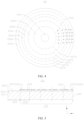
- FIG. 4 is a schematic structural diagram of an electrode assembly 22 according to some embodiments of this application;
- FIG. 5 is a schematic diagram of an unwound first electrode plate 221 according to some embodiments of this application;
- FIG. 6 is a schematic diagram of dimensions of an unwound first electrode plate according to some embodiments of this application.
- the battery cell 20 includes the electrode assembly 22.
- the electrode assembly 22 includes a first electrode plate 221.
- a plurality of weld portions 222 are disposed on one side of the first electrode plate in a width direction X, and the plurality of weld portions 222 are spaced apart along a length direction Y of the first electrode plate.
- the electrode assembly 22 has a j elly-roll structure.
- the first electrode plate 221 includes a winding start end 223 and a winding termination end 224.
- a weld portion closest to the winding start end 223 among the plurality of weld portions 222 is a first weld portion 222a.
- a weld portion closest to the winding termination end 224 among the plurality of weld portions 222 is a second weld portion 222b.
- the first electrode plate 221 includes a body section 225.
- the body section 225 is from an edge of the first weld portion 222a to an edge of the second weld portion 222b, the edge of the first weld portion being close to the winding start end 223, and the edge of the second weld portion being close to the winding termination end 224.
- the body section 225 is equally divided into a plurality of subsections 2251, each subsection being L in length.
- a total length of the weld portions 222 of each subsection 2251 is not less than 5% ⁇ L, where 200 mm ⁇ L ⁇ 1200 mm.
- the first electrode plate 221 includes a coated region 2211 coated with an active material layer and an uncoated region 2212 not coated with the active material layer.
- the first electrode plate 221 may be a positive electrode plate or a negative electrode plate.
- the electrode assembly 22 further includes a second electrode plate. If the first electrode plate 221 is a positive electrode plate, the coated region 2211 is coated with a positive active material, and the second electrode plate is a negative electrode plate. If the first electrode plate 221 is a negative electrode plate, the coated region 2211 is coated with a negative active material, and the second electrode plate is a positive electrode plate.
- the tab of the electrode assembly 22 is an all-tab of a jelly-roll type electrode assembly, the tab of the first electrode plate 221 and the tab of the second electrode plate are located at two axial ends of the electrode assembly 22 respectively.
- the winding start end 223 means a start point of winding the first electrode plate 221 in a case of winding the first electrode plate 221 to form the electrode assembly 22. After completion of the winding, the winding start end 223 is located at the innermost side of the electrode assembly 22 relative to other positions of the first electrode plate 221.
- the winding termination end 224 means a termination point of winding the first electrode plate 221 in a case of winding the first electrode plate 221 to form the electrode assembly 22. After completion of the winding, the winding termination end 224 is located at the outermost side of the electrode assembly 22 relative to other positions of the first electrode plate 221.
- the length of a weld portion 222 means a distance between an edge of the weld portion 222 close to the winding start end 223 and an edge close to the winding termination end 224, that is, the dimension of the weld portion 222 in the length direction Y of the first electrode plate.
- the total length of the weld portions 222 of the subsection 2251 means a sum of the lengths of all the weld portions 222 of the subsection 2251.
- Each subsection 2251 may include one or more weld portions 222.
- the plurality of weld portions 222 may be evenly spaced apart or unevenly spaced apart.
- the length of the body section 225 needs to be not less than the sum of the lengths of the two subsections 2251. That is, the body section 225 is equally divided into at least two subsections 2251.
- the flattened tab of the first electrode plate 221 of the electrode assembly 22 is divided along the radial direction into a plurality of regions around a winding center of the electrode assembly 22.
- Each region includes at least one circle of the first electrode plate 221.
- Each region may include one or more subsections 2251.
- Each subsection 2251 may be wound for at least one circle.
- the tab portion of the first electrode plate 221 is divided into six concentrically arranged regions.
- the six regions are defined as a first region 226a, a second region 226b, a third region 226c, a fourth region 226d, a fifth region 226e, and a sixth region 226f respectively from inside out.
- the six regions are delineated by a first circle 227a, a second circle 227b, a third circle 227c, a fourth circle 227d, and a fifth circle 227e shown by dashed lines, respectively.
- Each region includes a subsection 2251.
- the term "from inside out” in this application is termed relative to the winding center of the electrode assembly 22. Of two regions, one close to the winding center is located inside the one away from the winding center.
- a discharge internal resistance of the battery discharged within 0.1 second is used as an ohmic resistance.
- the value of the ohmic resistance affects the charge-and-discharge internal resistance and the charge-and-discharge flow capacity of the battery cell 20.
- SOC State of charge
- the SOC value 0 means a fully discharged state of the battery.
- the SOC value 1 means a fully charged state of the battery.
- the ohmic internal resistance and full-battery internal resistance of the battery cell 20 are tested by using a SOC value 0.5 as an example. To obtain the full-battery internal resistance of the battery cell 20, a direct-current internal resistance (DCIR) test is carried out.
- DCIR direct-current internal resistance
- the full-battery internal resistance of the battery cell 20 includes two parts: ohmic internal resistance and polarization internal resistance.
- the direct-current internal resistance (DCIR) test is a process of measuring the internal resistance by taking both parts into account.
- the DCIR is also known as a dynamic internal resistance.
- both the ohmic internal resistance and full-battery internal resistance of the battery cell 20 decrease gradually with the increase of the ratio of the total length of weld portions 222 of the subsection 2251 to the length of the subsection 2251.
- the ratio of the total length of weld portions 222 of the subsection 2251 to the length of the subsection 2251 is greater than or equal to 5%, both the ohmic internal resistance and full-battery internal resistance of the battery cell 20 tend to be stable.
- the total length of weld portions 222 of the subsection 2251 in this application is not less than 5% of the length of the subsection 2251, so that the battery cell 20 possesses a relatively low charge-and-discharge internal resistance and a relatively high charge-and-discharge flow capacity.
- the current collection component 24 (shown in FIG. 3 ) is welded to the electrode assembly 22 by continuous linear laser welding or pulsation welding, leaving weld marks to be X-shaped, ring-shaped, or the like.
- weld marks As can be seen from an unwound electrode plate, along a length direction of the electrode plate, the weld portions in some sections are relatively dense, the weld portions in other sections are relatively sparse, and the distribution of the weld portions on the electrode plate is nonuniform.
- an effective welding length of the electrode plate that is, a total length of the weld portions of the section) is not enough to match the length of the electrode plate.
- the body portion defined by the first weld portion 222a and the second weld portion 222b on the first electrode plate 221 is divided into a plurality of subsections 2251 of equal length along the length direction Y of the first electrode plate, the first weld portion being close to the winding start end 223, and the second weld portion being close to the winding termination end 224.
- a total length of the weld portions 222 of each subsection 2251 is not less than 5% of the length of the subsection 2251. In this way, the distribution of the weld portions 222 formed by the welding between the first electrode plate 221 and the current collection component 24 is more reasonable, thereby reducing the internal resistance of the battery cell 20, satisfying the practical flow capacity requirement, and in turn, improving the power performance of the battery cell 20.
- the length of each subsection 2251 ranges from 200 mm to 1200 mm, thereby making the winding length of the first electrode plate 221 meet practical product requirements and achieving a relatively high energy density of the battery cell 20.
- an absolute value of a difference of the total length of the weld portions 222 between any two subsections 2251 is less than or equal to 10 mm.
- the lengths of the weld portions 222 in one of any two subsections 2251 are defined as L 1 , ..., L n , respectively; and the lengths of the weld portions 222 in the other of any two subsections 2251 are defined as H 1 , ..., H m , where n and m are both natural numbers greater than or equal to 1, satisfying: -10 mm ⁇ (L 1 +...+ L n ) - (Hi +...+ H m ) ⁇ 10 mm.
- the absolute value of the difference of the total length of the weld portions 222 between any two subsections 2251 is minimized, thereby making the distribution of the weld portions 222 more reasonable, reducing the internal resistance of the battery cell 20, making the flow capacity difference relatively small between different subsections 2251, meeting the practical flow capacity requirement, and in turn, improving the power performance of the battery cell 20.
- Controlling the absolute value of the difference of the total length of the weld portions 222 between any two subsections 2251 to be less than or equal to 10 mm is equivalent to controlling a discrepancy of the welding width between different subsections 2251 to be less than or equal to 10 mm. Allowing the discrepancy of the total welding length between the subsections 2251 can reduce welding difficulty.
- the total length of the weld portions 222 is identical between any two subsections 2251.
- That the total length of the weld portions 222 is identical between any two subsections 2251 means that the difference of the total length of the weld portions 222 between any two subsections 2251 is zero.
- an absolute value of a difference of the number of the weld portions 222 between any two subsections 2251 is less than or equal to 10.
- the absolute value of the difference of the number of the weld portions 222 between any two subsections 2251 is minimized, thereby reducing the internal resistance of the battery cell 20, making the flow capacity difference relatively small between different subsections 2251, meeting the practical flow capacity requirement, and in turn, improving the power performance of the battery cell 20.
- Controlling the absolute value of the difference of the number of the weld portions 222 between any two subsections 2251 to be less than or equal to 10 is equivalent to allowing a discrepancy of the number of the weld portions 222 between different subsections 2251. Allowing the discrepancy of the total welding length between the subsections 2251 can reduce welding difficulty.
- the number of the weld portions 222 is identical between any two subsections 2251.
- the second region 226b, the third region 226c, the fourth region 226d, the fifth region 226e, and the sixth region 226f each include a subsection 2251.
- the number of weld portions 222 is identical between the second region 226b, the third region 226c, the fourth region 226d, the fifth region 226e, and the sixth region 226f.
- the difference of the total length of the weld portions 222 between different subsections 2251 is minimized, thereby making the distribution of the weld portions 222 more reasonable, reducing the internal resistance of the battery cell 20, making the flow capacity identical between different subsections 2251, meeting the practical flow capacity requirement, and in turn, improving the power performance of the battery cell 20.
- the first electrode plate 221 further includes a winding start section 228 contiguous to the body section 225.
- the winding start section 228 is from the winding start end 223 to the edge of the first weld portion 222a, the edge being close to the winding start end 223.
- the body section 225 is contiguous to the winding start section 228 means that the winding start section 228 is directly connected to the body section 225.
- the circle formed by winding the winding start section 228 is located inside the circle formed by winding the body section 225.
- the winding start section 228 is located in the first region 226a, and includes no weld portion 222.
- the first electrode plate 221 may include only the winding start section 228 and the body section 225. In some other embodiments, the first electrode plate 221 may include only the body section 225.
- the winding start section 228 is from the winding start end 223 to the edge of the first weld portion 222a, the edge being close to the winding start end 223.
- the winding start end 223 and the edge of the first weld portion 222a define the winding start section 228, the edge of the first weld portion being close to the winding start end 223.
- the winding start end 223 goes beyond the first weld portion 222a.
- No weld portion 222 is formed on the winding start section 228, so that there is no welding relationship between the winding start section 228 and the current collection component 24 (shown in FIG. 3 ), and a part of the current collection component 24 (shown in FIG. 3 ) corresponding to the tab of the winding start section 228 is not welded, and may be configured to be welded to the electrode terminal 232, so as to output electrical energy of the battery cell 20.
- the length of the winding start section 228 may vary between different battery cells 20.
- the winding start section 228 is A in length, and satisfies A ⁇ L.
- the length of the winding start section 228 means, when the first electrode plate 221 is in an unwound state, a distance between the winding start end 223 and the edge of the first weld portion 222a, the edge being close to the winding start end 223.
- the distance between the winding start end 223 and the first weld portion 222a is less than a length of a subsection.
- the length of the winding start section 228 without a weld portion 222 is less than the length of a subsection 2251 with a weld portion 222, thereby preventing the section without a weld portion 222 on the first electrode plate 221 from being excessively long, and ensuring stable output of electrical energy of the battery cell 20.
- FIG. 7 is a schematic structural diagram of an electrode assembly 22 according to some other embodiments of this application;
- FIG. 8 is a schematic diagram of an unwound first electrode plate 221 according to some other embodiments of this application;
- FIG. 9 is a schematic diagram of dimensions of an unwound first electrode plate 221 according to some other embodiments of this application.
- the first electrode plate 221 further includes a winding termination section 229 contiguous to the body section 225.
- the winding termination section 229 is from the winding termination end 224 to the edge of the second weld portion 222b, the edge being close to the winding termination end 224.
- the body section 225 is contiguous to the winding termination section 229 means that the winding termination section 229 is directly connected to the body section 225.
- the circle formed by winding the winding termination section 229 is located outside the circle formed by winding the body section 225.
- the winding termination section 229 is located in the sixth region 226f, and includes no weld portion 222.
- the first electrode plate 221 may include only the winding termination section 229 and the body section 225. In some other embodiments, as shown in FIG. 10 and FIG. 11 , the first electrode plate 221 may include a winding start section 228, a body section 225, and a winding termination section 229 connected in sequence.
- the winding termination section 229 is from the winding termination end 224 to the edge of the second weld portion 222b, the edge being close to the winding termination end 224.
- the winding termination end 224 and the edge of the second weld portion 222b define the winding termination section 229, the edge of the second weld portion being close to the winding termination end 224.
- the winding termination end 224 goes beyond the second weld portion 222b.
- No weld portion 222 is formed on the winding termination section 229, so that there is no welding relationship between the winding termination section 229 and the current collection component 24 (shown in FIG. 3 ), and a part of the current collection component 24 (shown in FIG. 3 ) corresponding to the tab portion of the winding termination section 229 is not welded, and may be configured to be welded to the electrode terminal 232, so as to output electrical energy of the battery cell 20.
- the length of the winding termination section 229 may vary between different battery cells 20.
- the length of the winding termination section 229 needs to make the electrode assembly 22 meet the practical requirements.
- the winding termination section 229 is B in length, and satisfies B ⁇ L.
- the length of the winding termination section 229 means a distance between the winding termination end 224 and the edge of the second weld portion 222b, the edge being close to the winding termination end 224.
- the length of the winding termination section 229 is less than the length of the subsection 2251.
- the length of the winding start section 228 without a weld portion 222 is less than the length of a subsection 2251 with a weld portion 222, thereby preventing the section without a weld portion 222 on the first electrode plate 221 from being excessively long, and ensuring stable output of electrical energy of the battery cell 20.
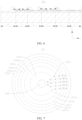
- FIG. 12 is a schematic diagram of an electrode assembly 22 according to still other embodiments of this application; and FIG. 13 is a schematic structural diagram of an electrode assembly 22 according to yet other embodiments of this application.
- the number of the weld portions 222 of a circle close to a winding center of the electrode assembly 22 is less than the number of the weld portions 222 of a circle away from the winding center.
- the "two adjacent circles of the first electrode plate 221" may be any two adjacent circles among all circles of the first electrode plate 221, or may be two adjacent circles among just a part of circles of the first electrode plate 221.
- each region includes one circle of the first electrode plate 221.
- each circle of the first electrode plate 221 includes two weld portions 222; in the second region 226b, each circle of the first electrode plate 221 includes four weld portions 222; in the third region 226c, each circle of the first electrode plate 221 includes six weld portions 222; in the fourth region 226d, each circle of the first electrode plate 221 includes six weld portions 222; and, in the fifth region 226e, each circle of the first electrode plate 221 includes six weld portions 222.
- the weld portions 222 are radially distributed.
- each region includes one circle of the first electrode plate 221.
- some circles of the first electrode plate 221 each include four weld portions 222
- some circles of the first electrode plate 221 each include five weld portions 222
- other circles of the first electrode plate 221 each include six weld portions 222.
- each circle of the first electrode plate 221 includes six weld portions 222.
- each circle of the first electrode plate 221 includes six weld portions 222.
- each circle of the first electrode plate 221 includes six weld portions 222.
- each circle of the first electrode plate 221 includes six weld portions 222.
- some circles of the first electrode plate 221 each include six weld portions 222, and other circles of the first electrode plate 221 each include five weld portions 222.
- Some weld portions 222 are radially distributed, and some weld portions 222 are connected to form an arc segment around the winding center of the electrode assembly 22.
- the arc segment is located in the sixth region 226f.
- the arc segment connects two adjacent radial lines among a plurality of radial lines, each radial line being formed of the weld portions 222.
- the number of the weld portions 222 may be identical between any two adjacent circles of the first electrode plate 221.
- the length of the circle close to the winding center is less than the length of the circle away from the winding center.
- the number of weld portions 222 formed on the circle close to the winding center of the jelly-roll type electrode assembly 22 is smaller than the number of weld portions 222 formed on the circle away from the winding center.
- each circle of the first electrode plate 221 and the corresponding number of the weld portions 222 on each circle of the first electrode plate 221 match the total length of the weld portions 222, thereby making the distribution of the weld portions 222 more reasonable, reducing the internal resistance of the battery cell 20, meeting the practical flow capacity requirement, and in turn, improving the power performance of the battery cell 20.
- the battery cell 20 further includes a housing 21, an end cap assembly 23, and a current collection component 24.
- the housing 21 is configured to accommodate the electrode assembly 22.
- the housing 21 includes an opening 211.
- the end cap assembly 23 includes an end cap 231 and electrode terminals 232.
- the end cap 231 is configured to cover the opening 211.
- Each electrode terminal 232 is mounted on the end cap 231.
- the current collection component 24 is located between the end cap 231 and the electrode assembly 22, and configured to connect a tab portion of the electrode assembly 22 to the electrode terminal 232.
- the tab portion is formed by winding an uncoated portion of the first electrode plate 221. At least a part of the current collection component 24 is welded to the tab portion to form the plurality of weld portions 222.
- At least a part of the current collection component 24 is welded to the tab portion to form the plurality of weld portions 222.
- the body portion defined by the first weld portion 222a and the second weld portion 222b on the first electrode plate 221 is divided into a plurality of subsections 2251 of equal length along the length direction Y of the first electrode plate, the first weld portion being close to the winding start end 223, and the second weld portion being close to the winding termination end 224.
- a total length of the weld portions 222 of each subsection 2251 is not less than 5% of the length of the subsection 2251.
- the distribution of the weld portions 222 formed by the welding between the first electrode plate 221 and the current collection component 24 is more reasonable, thereby reducing the internal resistance of the battery cell 20, satisfying the practical flow capacity requirement, and in turn, improving the power performance of the battery cell 20.
- FIG. 14 is a schematic diagram of a welded current collection component 24 according to some embodiments of this application.
- the first electrode plate 221 further includes a winding start section 228 from the winding start end 223 to the edge of the first weld portion 222a, the edge being close to the winding start end 223.
- the uncoated region of the body section 225 is wound to form a first part 12 (not shown in the drawing), the uncoated region of the winding start section 228 is wound to form a second part 13 (not shown in the drawing), and the second part 13 is located inside the first part 12 along a radial direction.
- the current collection component 24 includes a first current collection portion 241 and a second current collection portion 242 arranged continuously along the radial direction.
- the first current collection portion 241 is arranged opposite to the first part 12 along the width direction X of the first electrode plate and is welded to the first part 12 to form the plurality of weld portions 222.
- the second current collection portion 242 is arranged opposite to the second part 13 along the width direction X of the first electrode plate and is welded to the electrode terminal 232.
- the width direction X of the first electrode plate is consistent with a winding axis direction of the electrode assembly 22.
- the uncoated region of the first electrode plate 221 is configured to form a tab of the first electrode plate 221. Therefore, both the first part 12 and the second part 13 are the tab of the first electrode plate 221. That the second part 13 is located inside the first part 12 along the radial direction may be: one portion of the second part 13 is located inside the first part 12, and the other portion of the second part 13 and a portion of the first part 12 are located on the same circumference; or, all of the second part 13 is located inside the first part 12, and the first part 12 is disposed peripherally around the second part 13.
- That the first current collection portion 241 is disposed opposite to the first part 12 along the width direction X of the first electrode plate means that, along the width direction X of the first electrode plate, a projection of the first part 12 on the current collection component 24 at least partly overlaps the first current collection portion 241. Welding to each other is performed at the overlap part to form a plurality of weld portions 222, thereby implementing electrical connection between the electrode assembly 22 and the current collection component 24.
- the second current collection portion 242 and the second current collection portion 242 are arranged continuously along the radial direction.
- the winding start section 228 is from the winding start end 223 to the edge of the first weld portion 222a, the edge being close to the winding start end 223.
- the winding start end 223 and the edge of the first weld portion 222a define the winding start section 228, the edge of the first weld portion being close to the winding start end 223.
- No weld portion 222 is formed on the winding start section 228, so that there is no welding relationship between the second part 13 and the current collection component 24, the second part being formed by winding the uncoated region of the winding start section 228.
- No weld marks are formed on the second current collection portion 242 opposite to the second part 13, thereby making it convenient to weld the current collection component 24 to the electrode terminal 232 through the second current collection portion 242 to output electrical energy of the battery cell 20.
- FIG. 15 is a schematic diagram of a welded current collection component 24 according to some other embodiments of this application.
- the first electrode plate 221 further includes a winding termination section 229 from the winding termination end 224 to the edge of the second weld portion 222b, the edge being close to the winding termination section 229.
- the uncoated region of the body section 225 is wound to form a first part 12
- the uncoated region of the winding termination section 229 is wound to form a third part (not shown in the drawing), and the third part is located outside the first part 12 along the radial direction.
- the current collection component 24 includes a first current collection portion 241 and a third current collection portion 243 arranged continuously along the radial direction.
- the first current collection portion 241 is arranged opposite to the first part 12 along the width direction X of the first electrode plate and is welded to the first part 12 to form the plurality of weld portions 222.
- the third current collection portion 243 is arranged opposite to the third part along the width direction X of the first electrode plate and is welded to the electrode terminal 232.
- the uncoated region of the first electrode plate 221 is configured to form a tab of the first electrode plate 221. Therefore, both the first part 12 and the third part are the tab of the first electrode plate 221. That the third part is located outside the first part 12 along the radial direction may be: one portion of the third part is located outside the first part 12, and the other portion of the third part and a portion of the first part 12 are located on the same circumference; or, all of the third part is located inside the first part 12, and the third part is disposed peripherally around the first part 12.
- FIG. 16 is a schematic diagram of a welded current collection component 24 according to still other embodiments of this application.
- the current collection component 24 may include a second current collection portion 242, a first current collection portion 241, and a third current collection portion 243 arranged from inside out along the radial direction.
- the first current collection portion 241 is welded to the first part 12.
- the second current collection portion 242 is arranged opposite to the second part 13 along the width direction X of the first electrode plate.
- the third current collection portion is arranged opposite to the third part along the width direction X of the first electrode plate.
- the second current collection portion 242 and the third current collection portion 243 are welded to the electrode terminal 232 to output electrical energy of the battery cell 20.
- the electrode assembly 22 is electrically connected to the current collection component 24.
- the third current collection portion 243 and the first current collection portion 241 are arranged continuously along the radial direction.
- the winding termination section 229 is from the winding termination end 224 to the edge of the second weld portion 222b, the edge being close to the winding termination end 224.
- the winding termination end 224 and the edge of the second weld portion 222b define the winding termination section 229, the edge of the second weld portion being close to the winding termination end 224.
- No weld portion 222 is formed on the winding termination section 229, so that there is no welding relationship between the third part and the current collection component 24, the third part being formed by winding the uncoated region of the winding termination section 229.
- No weld marks are formed on the third current collection portion 243 opposite to the third part, thereby making it convenient to weld the current collection component 24 to the electrode terminal 232 through the third current collection portion 243 to output electrical energy of the battery cell 20.
- An embodiment of this application provides a cylindrical battery, including a cylindrical housing 21, a cylindrical electrode assembly 22, a current collection component 24, and an end cap assembly 23.
- the electrode assembly 22 is accommodated in the housing.
- An end cap 231 of the end cap assembly 23 covers and seals an opening 211 of the housing 21.
- the electrode assembly 22 includes a first electrode plate 221.
- the first electrode plate 221 includes a winding start end 223 and a winding termination end 224.
- a weld portion closest to the winding start end 223 among a plurality of weld portions 222 is a first weld portion 222a.
- a weld portion closest to the winding termination end 224 among the plurality of weld portions 222 is a second weld portion 222b.
- the first electrode plate 221 includes a body section 225.
- the body section is from an edge of the first weld portion 222a to an edge of the second weld portion 222b, the edge of the first weld portion being close to the winding start end 223, and the edge of the second weld portion being close to the winding termination end 224.
- the body section 225 is equally divided into a plurality of subsections 2251, each subsection being L in length.
- a total length of the weld portions 222 of each subsection 2251 is not less than 5% ⁇ L, where 200 mm ⁇ L ⁇ 1200 mm.
- An absolute value of a difference of the total length of the weld portions 222 between any two subsections 2251 is less than or equal to 10 mm.
- the first electrode plate 221 further includes a winding start section 228 contiguous to the body section 225, and includes a winding termination section 229.
- the winding start section 228 is from the winding start end 223 to the edge of the first weld portion 222a, the edge being close to the winding start end 223.
- the winding termination section 229 is from the winding termination end 224 to the edge of the second weld portion 222b, the edge being close to the winding termination end 224.
- the winding start section 228 is A in length
- the winding termination section 229 is B in length, satisfying A ⁇ L, and B ⁇ L.
- the current collection component 24 includes a second current collection portion 242, a first current collection portion 241, and a third current collection portion 243 arranged continuously from inside out along a radial direction.
- An uncoated region of the body section 225 is wound to form a first part 12.
- An uncoated region of the winding start section 228 is wound to form a second part 13.
- An uncoated region of the winding termination section 229 is wound to form a third part.
- the first current collection portion 241 is arranged opposite to the first part 12 and is welded to the first part 12 to form a plurality of weld portions 222
- the second current collection portion 242 is arranged opposite to the second part 13 and is welded to an electrode terminal 232
- the third current collection portion 243 is arranged opposite to the third part and is welded to the electrode terminal 232, so as to output electrical energy of the cylindrical battery.
- An embodiment of this application further provides a battery 100, including the battery cell 20 according to any embodiment described above.
- An embodiment of this application further provides an electrical device, including the battery 100 according to the above embodiment.
Landscapes
- Chemical & Material Sciences (AREA)
- Chemical Kinetics & Catalysis (AREA)
- Electrochemistry (AREA)
- General Chemical & Material Sciences (AREA)
- Engineering & Computer Science (AREA)
- Manufacturing & Machinery (AREA)
- Secondary Cells (AREA)
- Connection Of Batteries Or Terminals (AREA)
Abstract
Description
- This application relates to the technical field of batteries, and in particular, to a battery cell, a battery, and an electrical device.
- Batteries are widely used in electronic devices such as a mobile phone, a notebook computer, an electric power cart, an electric vehicle, an electric airplane, an electric ship, an electric toy car, an electric toy ship, an electric toy airplane, and an electric tool.
- In the development of battery technology, power performance of a battery is also important in addition to safety performance of the battery. Due to a high internal resistance of existing batteries, the power performance of the batteries is relatively low. Therefore, how to enhance the power performance of the battery has become an urgent problem to be solved in the technical field of batteries.
- Some embodiments of this application provide a battery cell, a battery, and an electrical device to enhance power performance of the battery.
- According to a first aspect, an embodiment of this application provides a battery cell, including an electrode assembly. The electrode assembly includes a first electrode plate. A plurality of weld portions are disposed on one side of the first electrode plate along a width direction, and the plurality of weld portions are spaced apart along a length direction of the first electrode plate.
- The electrode assembly has a jelly-roll structure. The first electrode plate includes a winding start end and a winding termination end. A weld portion closest to the winding start end among the plurality of weld portions is a first weld portion. A weld portion closest to the winding termination end among the plurality of weld portions is a second weld portion. The first electrode plate includes a body section. The body section is from an edge of the first weld portion to an edge of the second weld portion, the edge of the first weld portion being close to the winding start end, and the edge of the second weld portion being close to the winding termination end. The body section is equally divided into a plurality of subsections, each subsection being L in length. A total length of the weld portions of each subsection is not less than 5%×L, where 200 mm ≤ L ≤ 1200 mm.
- In existing technologies, the current collection component is welded to the electrode assembly by continuous linear laser welding or pulsation welding, leaving weld marks to be X-shaped, ring-shaped, or the like. As can be seen from an unwound electrode plate, along a length direction of the electrode plate, the weld portions in some sections are relatively dense, the weld portions in other sections are relatively sparse, and the distribution of the weld portions on the electrode plate is nonuniform. For a section with sparse weld portions, an effective welding length of the electrode plate (that is, a total length of the weld portions of the section) is not enough to match the length of the electrode plate. Consequently, the flow capacity of electrical current between the electrode plate and the current collection component is low, and the internal resistance of the battery cell is high, thereby impairing the power performance of the battery cell. By contrast, in the above technical solution, after the current collection component is welded to one side of the first electrode plate along the width direction, a plurality of spaced-out weld portions are formed in the length direction of the first electrode plate. The body portion defined by the first weld portion and the second weld portion on the first electrode plate is divided into a plurality of subsections of equal length along the length direction of the first electrode plate, the first weld portion being close to the winding start end, and the second weld portion being close to the winding termination end. A total length of the weld portions of each subsection is not less than 5% of the length of the subsection. In this way, the distribution of the weld portions formed by the welding between the first electrode plate and the current collection component is more reasonable, thereby reducing the internal resistance of the battery cell, satisfying the practical flow capacity requirement, and in turn, improving the power performance of the battery cell. The length of the subsection ranges from 200 mm to 1200 mm, thereby making the winding length of the first electrode plate meet practical product requirements and achieving a relatively high energy density of the battery cell.
- In some embodiments in the first aspect of this application, an absolute value of a difference of the total length of the weld portions between any two subsections is less than or equal to 10 mm.
- In the above technical solution, by controlling the absolute value of the difference of the total length of the weld portions between any two subsections to be less than or equal to 10 mm, the difference of the total length of the weld portions between different subsections is minimized, thereby making the distribution of the weld portions more reasonable, reducing the internal resistance of the battery cell, making the flow capacity difference relatively small between different subsections, meeting the practical flow capacity requirement, and in turn, improving the power performance of the battery cell. Controlling the absolute value of the difference of the total length of the weld portions between any two subsections to be less than or equal to 10 mm is equivalent to controlling a discrepancy of the welding width between different subsections to be less than or equal to 10 mm. Allowing the discrepancy of the total welding length between the subsections can reduce welding difficulty.
- In some embodiments in the first aspect of this application, the total length of the weld portions is identical between any two subsections.
- In the above technical solution, when the total length of the weld portions is identical between any two subsections, there is no difference of the total length of the weld portions between different subsections, thereby making the distribution of the weld portions more reasonable, minimizing the internal resistance of the battery cell, making the flow capacity identical between different subsections, meeting the practical flow capacity requirement, and in turn, improving the power performance of the battery cell.
- In some embodiments in the first aspect of this application, an absolute value of a difference of a number of the weld portions between any two subsections is less than or equal to 10.
- In the above technical solution, by controlling the absolute value of the difference of the number of the weld portions between any two subsections to be less than or equal to 10, the difference of the total length of the weld portions between different subsections is minimized, thereby making the distribution of the weld portions more reasonable, reducing the internal resistance of the battery cell, making the flow capacity difference relatively small between different subsections, meeting the practical flow capacity requirement, and in turn, improving the power performance of the battery cell. Controlling the absolute value of the difference of the number of the weld portions between any two subsections to be less than or equal to 10 is equivalent to allowing a discrepancy of the number of the weld portions between different subsections. Allowing the discrepancy of the total welding length between the subsections can reduce welding difficulty.
- In some embodiments in the first aspect of this application, the number of the weld portions is identical between any two subsections.
- In the above technical solution, when the number of the weld portions is identical between any two subsections, the difference of the total length of the weld portions between different subsections is minimized, thereby making the distribution of the weld portions more reasonable, reducing the internal resistance of the battery cell, making the flow capacity identical between different subsections, meeting the practical flow capacity requirement, and in turn, improving the power performance of the battery cell.
- In some embodiments in the first aspect of this application, the first electrode plate further includes a winding start section contiguous to the body section. The winding start section is from the winding start end to the edge of the first weld portion, the edge being close to the winding start end.
- In the above technical solution, the winding start section is from the winding start end to the edge of the first weld portion, the edge being close to the winding start end. To be specific, the winding start end and the edge of the first weld portion define the winding start section, the edge of the first weld portion being close to the winding start end. No weld portion is formed on the winding start section, so that there is no welding relationship between the winding start section and the current collection component, thereby facilitating the welding between the current collection component and the electrode terminal to output electrical energy of the battery cell.
- In some embodiments in the first aspect of this application, the winding start section is A in length, satisfying A ≤ L.
- In the above technical solution, along the length direction of the first electrode plate, the distance between the winding start end and the first weld portion is less than a length of a characteristic section. To be specific, the length of the winding start section without a weld portion is less than the length of a subsection with a weld portion, thereby preventing the section without a weld portion on the first electrode plate from being excessively long, and ensuring stable output of electrical energy of the battery cell.
- In some embodiments in the first aspect of this application, the first electrode plate further includes a winding termination section contiguous to the body section. The winding termination section is from the winding termination end to the edge of the second weld portion, the edge being close to the winding termination end.
- In the above technical solution, the winding termination section is from the winding termination end to the edge of the second weld portion, the edge being close to the winding termination end. To be specific, the winding termination end and the edge of the second weld portion define the winding termination section, the edge of the second weld portion being close to the winding termination end. No weld portion is formed on the winding termination section. There is no welding relationship between the winding termination section and the corresponding current collection component, thereby facilitating the welding between the current collection component and the electrode terminal to output electrical energy of the battery cell.
- In some embodiments in the first aspect of this application, the winding termination section is B in length, satisfying B ≤ L.
- In the above technical solution, along the length direction of the first electrode plate, the length of the winding termination section is less than the length of the subsection. To be specific, the length of the winding start section without a weld portion is less than the length of a subsection with a weld portion, thereby preventing the section without a weld portion on the first electrode plate from being excessively long, and ensuring stable output of electrical energy of the battery cell.
- In some embodiments in the first aspect of this application, among two adjacent circles of the first electrode plate, a number of the weld portions of a circle close to a winding center of the electrode assembly is less than a number of the weld portions of a circle away from the winding center.
- In the above technical solution, for a jelly-roll type electrode assembly, among two adjacent circles of the first electrode plate, the length of the circle close to the winding center is less than the length of the circle away from the winding center. During welding, the number of weld portions formed on the circle close to the winding center of the jelly-roll type electrode assembly is smaller than the number of weld portions formed on the circle away from the winding center. In this way, the length of each circle of the first electrode plate and the corresponding number of the weld portions on each circle of the first electrode plate match the total length of the weld portions, thereby making the distribution of the weld portions more reasonable, reducing the internal resistance of the battery cell, meeting the practical flow capacity requirement, and in turn, improving the power performance of the battery cell.
- In some embodiments in the first aspect of this application, the battery cell further includes a housing, an end cap assembly, and a current collection component. The housing is configured to accommodate the electrode assembly. The housing includes an opening. The end cap assembly includes an end cap and electrode terminals. The end cap is configured to cover the opening. Each electrode terminal is mounted on the end cap. The current collection component is located between the end cap and the electrode assembly, and configured to connect a tab portion of the electrode assembly to the electrode terminal. The tab portion is formed by winding an uncoated portion of the first electrode plate. At least a part of the current collection component is welded to the tab portion to form the plurality of weld portions.
- In the above technical solution, at least a part of the current collection component is welded to the tab portion to form a plurality of weld portions. The body portion defined by the first weld portion and the second weld portion on the first electrode plate is divided into a plurality of subsections of equal length along the length direction of the first electrode plate, the first weld portion being close to the winding start end, and the second weld portion being close to the winding termination end. A total length of the weld portions of each subsection is not less than 5% of the length of the subsection. In this way, the distribution of the weld portions formed by the welding between the first electrode plate and the current collection component is more reasonable, thereby reducing the internal resistance of the battery cell, satisfying the practical flow capacity requirement, and in turn, improving the power performance of the battery cell.
- In some embodiments in the first aspect of this application, the first electrode plate further includes a winding start section from the winding start end to the edge of the first weld portion, the edge being close to the winding start end. The uncoated region of the body section is wound to form a first part, the uncoated region of the winding start section is wound to form a second part, and the second part is located inside the first part along a radial direction. The current collection component includes a first current collection portion and a second current collection portion arranged continuously along the radial direction. The first current collection portion is arranged opposite to the first part along the width direction of the first electrode plate and is welded to the first part to form the plurality of weld portions. The second current collection portion is arranged opposite to the second part along the width direction of the first electrode plate and is welded to the electrode terminal.
- In the above technical solution, the uncoated region of the body section is wound to form the first part welded to the first current collection portion of the current collection component, thereby implementing electrical connection between the electrode assembly and the current collection component. The winding start section is from the winding start end to the edge of the first weld portion, the edge being close to the winding start end. To be specific, the winding start end and the edge of the first weld portion define the winding start section, the edge of the first weld portion being close to the winding start end. No weld portion is formed on the winding start section, so that there is no welding relationship between the second part and the current collection component, the second part being formed by winding the uncoated region of the winding start section. No weld marks are formed on the second current collection portion opposite to the second part, thereby making it convenient to weld the current collection component to the electrode terminal through the second current collection portion to output electrical energy of the battery cell.
- In some embodiments in the first aspect of this application, the first electrode plate further includes a winding termination section from the winding termination end to the edge of the second weld portion, the edge being close to the winding termination end. The uncoated region of the body section is wound to form a first part, the uncoated region of the winding termination section is wound to form a third part, and the third part is located outside the first part along a radial direction. The current collection component includes a first current collection portion and a third current collection portion arranged continuously along the radial direction. The first current collection portion is arranged opposite to the first part along the width direction of the first electrode plate and is welded to the first part to form the plurality of weld portions. The third current collection portion is arranged opposite to the third part along the width direction of the first electrode plate and is welded to the electrode terminal.
- In the above technical solution, the uncoated region of the body section is wound to form the first part welded to the first current collection portion of the current collection component, thereby implementing electrical connection between the electrode assembly and the current collection component. The winding termination section is from the winding termination end to the edge of the second weld portion, the edge being close to the winding termination end. To be specific, the winding termination end and the edge of the second weld portion define the winding termination section, the edge of the second weld portion being close to the winding termination end. No weld portion is formed on the winding termination section, so that there is no welding relationship between the third part and the current collection component, the third part being formed by winding the uncoated region of the winding termination section. Therefore, no weld marks are formed on the third current collection portion opposite to the third part, thereby making it convenient to weld the current collection component to the electrode terminal through the third current collection portion to output electrical energy of the battery cell.
- According to a second aspect, an embodiment of this application provides a battery, including the battery according to any embodiment according to the first aspect.
- In the above technical solution, a battery containing the battery cell disclosed in an embodiment in the first aspect of this application is provided. The body portion defined by the first weld portion and the second weld portion on the first electrode plate of the battery cell is divided into a plurality of subsections of equal length, the first weld portion being close to the winding start end, and the second weld portion being close to the winding termination end. A total length of the weld portions of each subsection is not less than 5% of the length of the subsection. In this way, the distribution of the weld portions formed by the welding between the first electrode plate and the current collection component is more reasonable, thereby reducing the internal resistance of the battery cell, satisfying the practical flow capacity requirement, and in turn, improving the power performance of the battery.
- According to a third aspect, an embodiment of this application provides an electrical device, including the battery according to any embodiment in the second aspect of this application.
- In the above technical solution, the electrical device employs the battery provided by an embodiment in the second aspect of this application. The body portion defined by the first weld portion and the second weld portion on the first electrode plate of the battery cell is divided into a plurality of subsections of equal length, the first weld portion being close to the winding start end, and the second weld portion being close to the winding termination end. A total length of the weld portions of each subsection is not less than 5% of the length of the subsection. In this way, the distribution of the weld portions formed by the welding between the first electrode plate and the current collection component is more reasonable, thereby reducing the internal resistance of the battery, satisfying the practical flow capacity requirement, and in turn, improving the power performance of the battery.
- To describe technical solutions in embodiments of this application more clearly, the following outlines the drawings to be used in the embodiments. It will be understood that the following drawings show merely some embodiments of this application, and therefore, are not intended to limit the scope. A person of ordinary skill in the art may derive other related drawings from the drawings without making any creative efforts.
-
FIG. 1 is a schematic structural diagram of a vehicle according to some embodiments of this application; -
FIG. 2 is a schematic structural diagram of a battery according to some embodiments of this application; -
FIG. 3 is an exploded view of a battery cell according to some embodiments of this application; -
FIG. 4 is a schematic structural diagram of an electrode assembly according to some embodiments of this application; -
FIG. 5 is a schematic diagram of an unwound first electrode plate according to some embodiments of this application; -
FIG. 6 is a schematic diagram of dimensions of an unwound first electrode plate according to some embodiments of this application; -
FIG. 7 is a schematic structural diagram of an electrode assembly according to some other embodiments of this application; -
FIG. 8 is a schematic diagram of an unwound first electrode plate according to some other embodiments of this application; -
FIG. 9 is a schematic diagram of dimensions of an unwound first electrode plate according to some other embodiments of this application; -
FIG. 10 is a schematic diagram of an unwound first electrode plate according to still other embodiments of this application; -
FIG. 11 is a schematic diagram of dimensions of an unwound first electrode plate according to still other embodiments of this application; -
FIG. 12 is a schematic diagram of an electrode assembly according to still other embodiments of this application; -
FIG. 13 is a schematic structural diagram of an electrode assembly according to yet other embodiments of this application; -
FIG. 14 is a schematic diagram of a welded current collection component according to some embodiments of this application; -
FIG. 15 is a schematic diagram of a welded current collection component according to some other embodiments of this application; and -
FIG. 16 is a schematic diagram of a welded current collection component according to still other embodiments of this application. - List of reference numerals: 1000-vehicle; 100-battery; 10-box; 11-accommodation space; 12-first part; 13-second part; 20-battery cell; 21-housing; 211-opening; 22-electrode assembly; 221-first electrode plate; 2211-coated region; 2212-uncoated region; 222-weld portion; 222a-first weld portion; 222b-second weld portion; 223-winding start end; 224-winding termination end; 225-body section; 2251-subsection; 226-winding center hole; 226a-first region; 226b-second region; 226c-third region; 226d-fourth region; 226e-fifth region; 226f-sixth region; 227a-first circle; 227b-second circle; 227c-third circle; 227d-fourth circle; 227e-fifth circle; 228-winding start section; 229-winding termination section; 23-end cap assembly; 231-end cap; 232-electrode terminal; 24-current collection component; 241-first current collection portion; 242-second current collection portion; 243-third current collection portion; 200-controller; 300-motor; X-width direction of first electrode plate; Y-length direction of first electrode plate.
- To make the objectives, technical solutions, and advantages of the embodiments of this application clearer, the following gives a clear and complete description of the technical solutions in the embodiments of this application with reference to the drawings in the embodiments of this application. It will be apparent that the described embodiments are merely a part of but not all of the embodiments of this application. The components described and illustrated in the drawings according to the embodiments of this application generally may be arranged and designed in a variety of different configurations.
- Therefore, the following detailed description of the embodiments of this application provided with reference to the drawings is not intended to limit the scope of this application as claimed, but merely represents selected embodiments of this application. All other embodiments derived by a person of ordinary skill in the art based on the embodiments of this application without making any creative efforts still fall within the protection scope of this application.
- It is hereby noted that, to the extent that no conflict occurs, the embodiments of this application and the features in the embodiments may be combined with each other.
- It is hereby noted that similar reference numerals and letters indicate similar items in the following drawings. Therefore, once an item is defined in one drawing, the item does not need to be further defined or construed in subsequent drawings.
- In the description of the embodiments of this application, it is hereby noted that an indicated direction or positional relationship is a direction or positional relationship based on illustration in the drawings, or a direction or positional relationship by which a product in use according to this application is usually placed, or a direction or positional relationship commonly understood by a person skilled in the art, and is merely intended for ease or brevity of describing this application, but does not indicate or imply that the indicated apparatus or component is necessarily located in the specified direction or constructed or operated in the specified direction. Therefore, the indicated direction or positional relationship is never to be understood as a limitation on this application. In addition, the terms "first", "second", and "third" are merely intended for distinct description, but not intended to indicate or imply order of precedence.
- Currently, as can be seen from the market trend, the application of power batteries is increasingly extensive. Power batteries are not only used in energy storage power systems such as hydro, thermal, wind, and solar power stations, but also widely used in electric means of transport such as electric bicycles, electric motorcycles, and electric vehicles, and used in many other fields such as military equipment and aerospace. The market demand for power batteries keeps soaring with the increase of the application fields of the power batteries.
- The inventor hereof is aware that a battery cell includes a housing, an end cap assembly, and an electrode assembly. The end cap assembly fits and covers the housing to provide a hermetically sealed space for the electrode assembly and an electrolytic solution. Electrical energy of the electrode assembly may be output out of the housing through electrode terminals on the end cap assembly. The electrode assembly is welded to the current collection component through a tab. An electrode terminal is electrically connected to the current collection component to output electrical energy of the battery. The electrode assembly includes an electrode plate. The electrode plate includes a coated region coated with an active material layer and an uncoated region not coated with the active material layer. The uncoated region of the electrode plate is wound to form a tab portion. The current collection component is welded to the tab portion to form a plurality of weld portions.
- For a jelly-roll all-tab electrode assembly, the tab needs to be flattened before being welded to the current collection component. In existing technologies, the current collection component is welded to the electrode assembly by continuous linear laser welding or pulsation welding, leaving weld marks to be X-shaped, ring-shaped, or the like. As can be seen from an unwound electrode plate, along a length direction of the electrode plate, the weld portions in some sections are relatively dense, the weld portions in other sections are relatively sparse, and the distribution of the weld portions on the electrode plate is nonuniform. For a section with sparse weld portions, an effective welding length of the electrode plate (that is, a total length of the weld portions of the section) is not enough to match the length of the electrode plate. Consequently, the flow capacity of electrical current between the electrode plate and the current collection component is low, and the internal resistance of the battery cell is high, thereby impairing the power performance of the battery cell.
- In view of the above situation, in order to solve the problem that unreasonable distribution of weld positions between the electrode plate and the current collection component leads to a high internal resistance and a low flow capacity of the battery cell, the inventor has designed a battery cell after in-depth research. In the battery cell, a body portion defined by a first weld portion and a second weld portion on a first electrode plate is divided into a plurality of subsections of equal length, the first weld portion being close to a winding start end, and the second weld portion being close to the winding termination end. A total length of the weld portions of each subsection is not less than 5% of the length of the subsection. In this way, the distribution of the weld portions formed by the welding between the first electrode plate and the current collection component is more reasonable, thereby reducing the internal resistance of the battery cell, satisfying the practical flow capacity requirement, and in turn, improving the power performance of the battery cell.
- The technical solutions described in this embodiment of this application are applicable to a battery and an electrical device that uses the battery.
- The electrical device may be a vehicle, a mobile phone, a portable device, a notebook computer, a ship, a spacecraft, an electric toy, a power tool, or the like. The vehicle may be an oil-fueled vehicle, a natural gas vehicle, or a new energy vehicle. The new energy vehicle may be a battery electric vehicle, a hybrid electric vehicle, a range-extended electric vehicle, or the like. The spacecraft includes an airplane, a rocket, a space shuttle, a spaceship, and the like. The electric toy includes a fixed or mobile electric toy, such as a game console, an electric car toy, an electric ship toy, an electric airplane toy, and the like. The power tool includes an electrical metal cutting tool, an electrical grinding tool, an electrical assembling tool, and a power tool for use in railways. Examples of the power tool are an electrical drill, an electrical grinder, an electrical wrench, an electrical screwdriver, an electrical hammer, an electrical impact drill, a concrete vibrator, an electrical planer, and the like. The electrical device is not particularly limited in this embodiment of this application.
- For ease of description in the following embodiments, a vehicle is used as an example of the electrical device.
- Referring to
FIG. 1, FIG. 1 is a schematic structural diagram of avehicle 1000 according to some embodiments of this application. Abattery 100 is disposed inside thevehicle 1000. Thebattery 100 may be disposed at the bottom, front, or rear of thevehicle 1000. Thebattery 100 may be configured to supply power to thevehicle 1000. For example, thebattery 100 may serve as an operating power supply of thevehicle 1000. - The
vehicle 1000 may further include acontroller 200 and amotor 300. Thecontroller 200 is configured to control thebattery 100 to supply power to themotor 300, for example, to meet electrical energy requirements in starting, navigating, or running thevehicle 1000. - In some embodiments of this application, the
battery 100 serves not only as an operating power supply of thevehicle 1000, but may also serve as a drive power supply of thevehicle 1000 to provide driving power for thevehicle 1000 in place of or partly in place of oil or natural gas. - Referring to
FIG. 2, FIG. 2 is a schematic structural diagram of abattery 100 according to some embodiments of this application. Thebattery 100 includes a box 10 and abattery cell 20. Thebattery cell 20 is accommodated in the box 10. - The box 10 is configured to provide an
accommodation space 11 for thebattery cell 20. In some embodiments, the box 10 may include a first part 12 and a second part 13. The first part 12 and the second part 13 fit and cover each other to define theaccommodation space 11 configured to accommodate thebattery cell 20. Definitely, a junction between the first part 12 and the second part 13 may be sealed by a sealing element (not shown in the drawing). The sealing element may be a sealing ring, a sealant, or the like. - The first part 12 and the second part 13 may be in various shapes, such as a cuboid or cylinder. The first part 12 is a hollow structure opened up at one end, in which an accommodation portion configured to accommodate the
battery cell 20 is formed. The second part 13 may also be a hollow structure opened up at one side, in which an accommodation portion configured to accommodate thebattery cell 20 is formed. The open-up side of the second part 13 fits and covers the open-up side of the first part 12 to form a box 10 that includes a hermetically sealed space. Alternatively, the first part 12 is a hollow structure opened up at one end, in which an accommodation portion configured to accommodate thebattery cell 20 is formed, and the second part 13 is a plate-shaped structure. The second part 13 fits and covers the open-up side of the first part 12 to form the box 10 that includes a hermetically sealed space. - There may be one or
more battery cells 20 in thebattery 100. If there are a plurality ofbattery cells 20, the plurality ofbattery cells 20 may be connected in series, parallel, or series-and-parallel pattern. The series-and-parallel pattern means a combination of series connection and parallel connection of the plurality ofbattery cells 20. The plurality ofbattery cells 20 may be directly connected in series, parallel, or series-and-parallel pattern, and then the whole of the plurality ofbattery cells 20 may be accommodated in the box 10. Alternatively, the plurality ofbattery cells 20 may be connected in series, parallel, or series-and-parallel pattern to form a battery module first. A plurality of battery modules are then connected in series, parallel, or series-and-parallel pattern to form a whole for being accommodated in the box 10. Thebattery cell 20 may be in the shape of a cylinder, flat body, cuboid, or the like.FIG. 2 exemplarily shows abattery cell 20 in a cylindrical shape. - In some embodiments, the
battery 100 may further include a busbar component (not shown in the drawing). The plurality ofbattery cells 20 may be electrically connected by the busbar component, so as to implement series, parallel, or series-and-parallel connection between the plurality ofbattery cells 20. - Referring to
FIG. 3, FIG. 3 is an exploded view of abattery cell 20 according to some embodiments of this application. Thebattery cell 20 may include ahousing 21, anelectrode assembly 22, and anend cap assembly 23. Thehousing 21 includes anopening 211. Theelectrode assembly 22 is accommodated in thehousing 21. Theend cap assembly 23 is configured to cover and seal theopening 211. - The
housing 21 may be in various shapes such as a cylinder or cuboid. The shape of thehousing 21 may be determined depending on the specific shape of theelectrode assembly 22. For example, if theelectrode assembly 22 is a cylindrical structure, thehousing 21 may be a cylindrical structure. If theelectrode assembly 22 is a cuboidal structure, thehousing 21 may be a cuboidal structure.FIG. 3 exemplarily shows ahousing 21 and anelectrode assembly 22 in a cylindrical shape. - The
housing 21 may be made of a variety of materials such as copper, iron, aluminum, stainless steel, or aluminum alloy, without being particularly limited herein. - The
electrode assembly 22 may include a positive electrode plate (not shown in the drawing), a negative electrode plate (not shown in the drawing), and a separator (not shown in the drawing). - The positive electrode plate includes a positive current collector and a positive active material layer. A surface of the positive current collector is coated with the positive active material layer. Of the positive current collector, a part uncoated with the positive active material layer protrudes from a part coated with the positive active material layer. The part, uncoated with the positive active material layer, of the positive current collector, serves as a positive tab. Using a lithium-ion battery as an example, the positive current collector may be made of aluminum, and a positive active material may be lithium cobalt oxide, lithium iron phosphate, ternary lithium, lithium manganese oxide, or the like. The negative electrode plate includes a negative current collector and a negative active material layer. A surface of the negative current collector is coated with the negative active material layer. Of the negative current collector, a part uncoated with the negative active material layer protrudes from a part coated with the negative active material layer, and the part uncoated with the negative active material layer serves as a negative tab. The negative current collector may be made of copper, and a negative active material may be carbon, silicon, or the like.
- The
electrode assembly 22 may be a jelly-roll structure formed by winding the positive electrode plate, the separator, and the negative electrode plate. Theelectrode assembly 22 further includes a positive tab (not shown in the drawing) and a negative tab (not shown in the drawing). The part, uncoated with a positive active material layer, of the positive current collector in the positive electrode plate may serve as the positive tab. The part, uncoated with a negative active material layer, of the negative current collector in the negative electrode plate may serve as the negative tab. - The
end cap assembly 23 is configured to cover and seal theopening 211 of thehousing 21 to form a hermetically sealed accommodation cavity (not shown in the drawing). The accommodation cavity is configured to accommodate theelectrode assembly 22. The accommodation cavity is further configured to accommodate an electrolyte such as an electrolytic solution. Theend cap assembly 23 is a component configured to output electrical energy of theelectrode assembly 22.Electrode terminals 232 in theend cap assembly 23 are configured to be electrically connected to theelectrode assembly 22. To be specific, theelectrode terminals 232 are electrically connected to tabs of theelectrode assembly 22. - It is hereby noted that the number of
openings 211 of thehousing 21 may be one or two. If the number ofopenings 211 of thehousing 21 is one, the number ofend cap assemblies 23 may also be one, and twoelectrode terminals 232 may be disposed in theend cap assembly 23. The twoelectrode terminals 232 are configured to be electrically connected to the positive tab and the negative tab of theelectrode assembly 22 respectively. The twoelectrode terminals 232 in theend cap assembly 23 are apositive electrode terminal 232 and anegative electrode terminal 232 respectively. As shown inFIG. 3 , if there are twoopenings 211 of thehousing 21, for example, if the twoopenings 211 are disposed on two opposite sides of thehousing 21 respectively, the number ofend cap assemblies 23 may be two. The twoend cap assemblies 23 fit and cover the twoopenings 211 of thehousing 21 respectively. In this case, theelectrode terminal 232 in oneend cap assembly 23 may be a positive electrode terminal and configured to be electrically connected to the positive tab of theelectrode assembly 22. Theelectrode terminal 232 in the otherend cap assembly 23 may be a negative electrode terminal and configured to be electrically connected to the negative electrode plate of theelectrode assembly 22. - Referring to
FIG. 4, FIG. 5 , andFIG. 6 ,FIG. 4 is a schematic structural diagram of anelectrode assembly 22 according to some embodiments of this application;FIG. 5 is a schematic diagram of an unwoundfirst electrode plate 221 according to some embodiments of this application; andFIG. 6 is a schematic diagram of dimensions of an unwound first electrode plate according to some embodiments of this application. Thebattery cell 20 includes theelectrode assembly 22. Theelectrode assembly 22 includes afirst electrode plate 221. A plurality ofweld portions 222 are disposed on one side of the first electrode plate in a width direction X, and the plurality ofweld portions 222 are spaced apart along a length direction Y of the first electrode plate. Theelectrode assembly 22 has a j elly-roll structure. Thefirst electrode plate 221 includes a windingstart end 223 and a windingtermination end 224. A weld portion closest to the windingstart end 223 among the plurality ofweld portions 222 is afirst weld portion 222a. A weld portion closest to the windingtermination end 224 among the plurality ofweld portions 222 is asecond weld portion 222b. Thefirst electrode plate 221 includes abody section 225. Thebody section 225 is from an edge of thefirst weld portion 222a to an edge of thesecond weld portion 222b, the edge of the first weld portion being close to the windingstart end 223, and the edge of the second weld portion being close to the windingtermination end 224. Thebody section 225 is equally divided into a plurality ofsubsections 2251, each subsection being L in length. A total length of theweld portions 222 of eachsubsection 2251 is not less than 5%×L, where 200 mm ≤ L ≤ 1200 mm. - Along the width direction X of the first electrode plate, the
first electrode plate 221 includes acoated region 2211 coated with an active material layer and anuncoated region 2212 not coated with the active material layer. Thefirst electrode plate 221 may be a positive electrode plate or a negative electrode plate. Theelectrode assembly 22 further includes a second electrode plate. If thefirst electrode plate 221 is a positive electrode plate, thecoated region 2211 is coated with a positive active material, and the second electrode plate is a negative electrode plate. If thefirst electrode plate 221 is a negative electrode plate, thecoated region 2211 is coated with a negative active material, and the second electrode plate is a positive electrode plate. In an embodiment in which the tab of theelectrode assembly 22 is an all-tab of a jelly-roll type electrode assembly, the tab of thefirst electrode plate 221 and the tab of the second electrode plate are located at two axial ends of theelectrode assembly 22 respectively. - The winding start end 223 means a start point of winding the
first electrode plate 221 in a case of winding thefirst electrode plate 221 to form theelectrode assembly 22. After completion of the winding, the windingstart end 223 is located at the innermost side of theelectrode assembly 22 relative to other positions of thefirst electrode plate 221. - The winding
termination end 224 means a termination point of winding thefirst electrode plate 221 in a case of winding thefirst electrode plate 221 to form theelectrode assembly 22. After completion of the winding, the windingtermination end 224 is located at the outermost side of theelectrode assembly 22 relative to other positions of thefirst electrode plate 221. - When the
first electrode plate 221 is in an unwound state, the length of aweld portion 222 means a distance between an edge of theweld portion 222 close to the windingstart end 223 and an edge close to the windingtermination end 224, that is, the dimension of theweld portion 222 in the length direction Y of the first electrode plate. The total length of theweld portions 222 of thesubsection 2251 means a sum of the lengths of all theweld portions 222 of thesubsection 2251. - Each
subsection 2251 may include one ormore weld portions 222. In an embodiment in which eachsubsection 2251 includes a plurality ofweld portions 222, the plurality ofweld portions 222 may be evenly spaced apart or unevenly spaced apart. - The length of the
body section 225 needs to be not less than the sum of the lengths of the twosubsections 2251. That is, thebody section 225 is equally divided into at least twosubsections 2251. - In practical welding, the flattened tab of the
first electrode plate 221 of theelectrode assembly 22 is divided along the radial direction into a plurality of regions around a winding center of theelectrode assembly 22. Each region includes at least one circle of thefirst electrode plate 221. Each region may include one or more subsections 2251. Eachsubsection 2251 may be wound for at least one circle. - Exemplarily, as shown in
FIG. 4 , around the windingcenter hole 226 of theelectrode assembly 22, the tab portion of thefirst electrode plate 221 is divided into six concentrically arranged regions. The six regions are defined as afirst region 226a, asecond region 226b, athird region 226c, afourth region 226d, afifth region 226e, and asixth region 226f respectively from inside out. InFIG. 4 , the six regions are delineated by afirst circle 227a, asecond circle 227b, athird circle 227c, afourth circle 227d, and afifth circle 227e shown by dashed lines, respectively. Each region includes asubsection 2251. - The term "from inside out" in this application is termed relative to the winding center of the
electrode assembly 22. Of two regions, one close to the winding center is located inside the one away from the winding center. - In the verification of a battery cell, a discharge internal resistance of the battery discharged within 0.1 second is used as an ohmic resistance. The value of the ohmic resistance affects the charge-and-discharge internal resistance and the charge-and-discharge flow capacity of the
battery cell 20. To determine how a ratio of the total length of theweld portions 222 of thesubsection 2251 to the length of thesubsection 2251 affects the charge-and-discharge internal resistance and charge-and-discharge flow capacity of thebattery cell 20, the following test is performed: - Test conditions: The length of the subsection is 800 mm. The ambient temperature of the test is 25 °C. State of charge (SOC) means a ratio of the remaining capacity of a battery cycled for a period of time or left unused for a long time to a fully charged capacity of the battery, usually expressed as a percentage. The value range of the SOC is 0 to 1. The SOC value 0 means a fully discharged state of the battery. The SOC value 1 means a fully charged state of the battery. In this application, the ohmic internal resistance and full-battery internal resistance of the
battery cell 20 are tested by using a SOC value 0.5 as an example. To obtain the full-battery internal resistance of thebattery cell 20, a direct-current internal resistance (DCIR) test is carried out. The full-battery internal resistance of thebattery cell 20 includes two parts: ohmic internal resistance and polarization internal resistance. The direct-current internal resistance (DCIR) test is a process of measuring the internal resistance by taking both parts into account. The DCIR is also known as a dynamic internal resistance.Table 1 Test results of ohmic internal resistance and full-battery internal resistance corresponding to different ratios of total length of weld portions to length of subsection DCIR measured at 25 °C and 0.5 SOC Type and serial number of specimen Total length of weld portions = 10% × L (mm) Total length of weld portions = 5.8% × L (mm) Total length of weld portions = 5% × L (mm) Total length of weld portions = 4.5% × L (mm) Total length of weld portions = 3% × L (mm) Specimen i Specimen ii Specimen iii Specimen iv Specimen v Specimen vi Specimen vii Specimen viii Specimen ix Specimen x Ohmic internal resistance 0.79 0.78 0.78 0.79 0.79 0.78 0.83 0.84 0.88 0.87 Full-battery internal resistance 1.12 1.11 1.11 1.11 1.11 1.11 1.11 1.12 1.21 1.20 - As can be seen from the above test results, when the ratio of the total length of
weld portions 222 of thesubsection 2251 to the length of thesubsection 2251 is 3% to 5%, both the ohmic internal resistance and full-battery internal resistance of thebattery cell 20 decrease gradually with the increase of the ratio of the total length ofweld portions 222 of thesubsection 2251 to the length of thesubsection 2251. When the ratio of the total length ofweld portions 222 of thesubsection 2251 to the length of thesubsection 2251 is greater than or equal to 5%, both the ohmic internal resistance and full-battery internal resistance of thebattery cell 20 tend to be stable. Therefore, the total length ofweld portions 222 of thesubsection 2251 in this application is not less than 5% of the length of thesubsection 2251, so that thebattery cell 20 possesses a relatively low charge-and-discharge internal resistance and a relatively high charge-and-discharge flow capacity. - In existing technologies, the current collection component 24 (shown in
FIG. 3 ) is welded to theelectrode assembly 22 by continuous linear laser welding or pulsation welding, leaving weld marks to be X-shaped, ring-shaped, or the like. As can be seen from an unwound electrode plate, along a length direction of the electrode plate, the weld portions in some sections are relatively dense, the weld portions in other sections are relatively sparse, and the distribution of the weld portions on the electrode plate is nonuniform. For a section with sparse weld portions, an effective welding length of the electrode plate (that is, a total length of the weld portions of the section) is not enough to match the length of the electrode plate. Consequently, the flow capacity of electrical current between the electrode plate and thecurrent collection component 24 is low, and the internal resistance of the battery cell is high, thereby impairing the power performance of thebattery cell 20. By contrast, in the above technical solution, after thecurrent collection component 24 is welded to one side of the first electrode plate along the width direction X, a plurality of spaced-outweld portions 222 are formed in the length direction Y of the first electrode plate. The body portion defined by thefirst weld portion 222a and thesecond weld portion 222b on thefirst electrode plate 221 is divided into a plurality ofsubsections 2251 of equal length along the length direction Y of the first electrode plate, the first weld portion being close to the windingstart end 223, and the second weld portion being close to the windingtermination end 224. A total length of theweld portions 222 of eachsubsection 2251 is not less than 5% of the length of thesubsection 2251. In this way, the distribution of theweld portions 222 formed by the welding between thefirst electrode plate 221 and thecurrent collection component 24 is more reasonable, thereby reducing the internal resistance of thebattery cell 20, satisfying the practical flow capacity requirement, and in turn, improving the power performance of thebattery cell 20. The length of eachsubsection 2251 ranges from 200 mm to 1200 mm, thereby making the winding length of thefirst electrode plate 221 meet practical product requirements and achieving a relatively high energy density of thebattery cell 20. - Referring to
FIG. 5 andFIG. 6 , in some embodiments, an absolute value of a difference of the total length of theweld portions 222 between any twosubsections 2251 is less than or equal to 10 mm. - In
FIG. 5 andFIG. 6 , the lengths of theweld portions 222 in one of any twosubsections 2251 are defined as L1, ..., Ln, respectively; and the lengths of theweld portions 222 in the other of any twosubsections 2251 are defined as H1, ..., Hm, where n and m are both natural numbers greater than or equal to 1, satisfying: -10 mm ≤ (L1 +...+ Ln) - (Hi +...+ Hm) ≤ 10 mm. - By controlling the absolute value of the difference of the total length of the
weld portions 222 between any twosubsections 2251 to be less than or equal to 10 mm, the difference of the total length of theweld portions 222 betweendifferent subsections 2251 is minimized, thereby making the distribution of theweld portions 222 more reasonable, reducing the internal resistance of thebattery cell 20, making the flow capacity difference relatively small betweendifferent subsections 2251, meeting the practical flow capacity requirement, and in turn, improving the power performance of thebattery cell 20. Controlling the absolute value of the difference of the total length of theweld portions 222 between any twosubsections 2251 to be less than or equal to 10 mm is equivalent to controlling a discrepancy of the welding width betweendifferent subsections 2251 to be less than or equal to 10 mm. Allowing the discrepancy of the total welding length between thesubsections 2251 can reduce welding difficulty. - In some embodiments, the total length of the
weld portions 222 is identical between any twosubsections 2251. - That the total length of the
weld portions 222 is identical between any twosubsections 2251 means that the difference of the total length of theweld portions 222 between any twosubsections 2251 is zero. - When the total length of the
weld portions 222 is identical between any twosubsections 2251, there is no difference of the total length of theweld portions 222 betweendifferent subsections 2251, thereby making the distribution of theweld portions 222 more reasonable, minimizing the internal resistance of thebattery cell 20, making the flow capacity identical betweendifferent subsections 2251, meeting the practical flow capacity requirement, and in turn, improving the power performance of thebattery cell 20. - In some embodiments, an absolute value of a difference of the number of the
weld portions 222 between any twosubsections 2251 is less than or equal to 10. - In
FIG. 5, -10 ≤ n - m ≤ 10. That is, the absolute value of the difference of the number of theweld portions 222 between any twosubsections 2251 is less than 10. - By controlling the absolute value of the difference of the number of the
weld portions 222 between any twosubsections 2251 to be less than or equal to 10 mm, the difference of the number of the weld portions betweendifferent subsections 2251 is minimized, thereby reducing the internal resistance of thebattery cell 20, making the flow capacity difference relatively small betweendifferent subsections 2251, meeting the practical flow capacity requirement, and in turn, improving the power performance of thebattery cell 20. Controlling the absolute value of the difference of the number of theweld portions 222 between any twosubsections 2251 to be less than or equal to 10 is equivalent to allowing a discrepancy of the number of theweld portions 222 betweendifferent subsections 2251. Allowing the discrepancy of the total welding length between thesubsections 2251 can reduce welding difficulty. - In some embodiments, the number of the
weld portions 222 is identical between any twosubsections 2251. - That the number of the
weld portions 222 is identical between any twosubsections 2251 means that the difference of the number of theweld portions 222 between any twosubsections 2251 is zero, that is, n - m = 0, as shown inFIG. 6 . As shown inFIG. 4 , thesecond region 226b, thethird region 226c, thefourth region 226d, thefifth region 226e, and thesixth region 226f each include asubsection 2251. The number ofweld portions 222 is identical between thesecond region 226b, thethird region 226c, thefourth region 226d, thefifth region 226e, and thesixth region 226f. - When the number of the
weld portions 222 is identical between any twosubsections 2251, the difference of the total length of theweld portions 222 betweendifferent subsections 2251 is minimized, thereby making the distribution of theweld portions 222 more reasonable, reducing the internal resistance of thebattery cell 20, making the flow capacity identical betweendifferent subsections 2251, meeting the practical flow capacity requirement, and in turn, improving the power performance of thebattery cell 20. - Still referring to
FIG. 4, FIG. 5 , andFIG. 6 , in some embodiments, thefirst electrode plate 221 further includes a windingstart section 228 contiguous to thebody section 225. The windingstart section 228 is from the windingstart end 223 to the edge of thefirst weld portion 222a, the edge being close to the windingstart end 223. - That the
body section 225 is contiguous to the windingstart section 228 means that the windingstart section 228 is directly connected to thebody section 225. After completion of the winding, the circle formed by winding the windingstart section 228 is located inside the circle formed by winding thebody section 225. As shown inFIG. 4, FIG. 5 , andFIG. 6 , the windingstart section 228 is located in thefirst region 226a, and includes noweld portion 222. - In some embodiments, the
first electrode plate 221 may include only the windingstart section 228 and thebody section 225. In some other embodiments, thefirst electrode plate 221 may include only thebody section 225. - The winding
start section 228 is from the windingstart end 223 to the edge of thefirst weld portion 222a, the edge being close to the windingstart end 223. To be specific, the windingstart end 223 and the edge of thefirst weld portion 222a define the windingstart section 228, the edge of the first weld portion being close to the windingstart end 223. In other words, the windingstart end 223 goes beyond thefirst weld portion 222a. Noweld portion 222 is formed on the windingstart section 228, so that there is no welding relationship between the windingstart section 228 and the current collection component 24 (shown inFIG. 3 ), and a part of the current collection component 24 (shown inFIG. 3 ) corresponding to the tab of the windingstart section 228 is not welded, and may be configured to be welded to theelectrode terminal 232, so as to output electrical energy of thebattery cell 20. - The length of the winding
start section 228 may vary betweendifferent battery cells 20. In some embodiments, the windingstart section 228 is A in length, and satisfies A ≤ L. - The length of the winding
start section 228 means, when thefirst electrode plate 221 is in an unwound state, a distance between the windingstart end 223 and the edge of thefirst weld portion 222a, the edge being close to the windingstart end 223. - Along the length direction Y of the first electrode plate, the distance between the winding
start end 223 and thefirst weld portion 222a is less than a length of a subsection. To be specific, the length of the windingstart section 228 without aweld portion 222 is less than the length of asubsection 2251 with aweld portion 222, thereby preventing the section without aweld portion 222 on thefirst electrode plate 221 from being excessively long, and ensuring stable output of electrical energy of thebattery cell 20. - Referring to
FIG. 7 ,FIG. 8, and FIG. 9 ,FIG. 7 is a schematic structural diagram of anelectrode assembly 22 according to some other embodiments of this application;FIG. 8 is a schematic diagram of an unwoundfirst electrode plate 221 according to some other embodiments of this application; andFIG. 9 is a schematic diagram of dimensions of an unwoundfirst electrode plate 221 according to some other embodiments of this application. In some embodiments, thefirst electrode plate 221 further includes a windingtermination section 229 contiguous to thebody section 225. The windingtermination section 229 is from the windingtermination end 224 to the edge of thesecond weld portion 222b, the edge being close to the windingtermination end 224. - That the
body section 225 is contiguous to the windingtermination section 229 means that the windingtermination section 229 is directly connected to thebody section 225. After completion of the winding, the circle formed by winding the windingtermination section 229 is located outside the circle formed by winding thebody section 225. As shown inFIG. 6 and FIG. 7 , the windingtermination section 229 is located in thesixth region 226f, and includes noweld portion 222. - In some embodiments, the
first electrode plate 221 may include only the windingtermination section 229 and thebody section 225. In some other embodiments, as shown inFIG. 10 andFIG. 11 , thefirst electrode plate 221 may include a windingstart section 228, abody section 225, and a windingtermination section 229 connected in sequence. - The winding
termination section 229 is from the windingtermination end 224 to the edge of thesecond weld portion 222b, the edge being close to the windingtermination end 224. To be specific, the windingtermination end 224 and the edge of thesecond weld portion 222b define the windingtermination section 229, the edge of the second weld portion being close to the windingtermination end 224. In other words, the windingtermination end 224 goes beyond thesecond weld portion 222b. Noweld portion 222 is formed on the windingtermination section 229, so that there is no welding relationship between the windingtermination section 229 and the current collection component 24 (shown inFIG. 3 ), and a part of the current collection component 24 (shown inFIG. 3 ) corresponding to the tab portion of the windingtermination section 229 is not welded, and may be configured to be welded to theelectrode terminal 232, so as to output electrical energy of thebattery cell 20. - The length of the winding
termination section 229 may vary betweendifferent battery cells 20. The length of the windingtermination section 229 needs to make theelectrode assembly 22 meet the practical requirements. In some embodiments, the windingtermination section 229 is B in length, and satisfies B ≤ L. - When the
first electrode plate 221 is in an unwound state, the length of the windingtermination section 229 means a distance between the windingtermination end 224 and the edge of thesecond weld portion 222b, the edge being close to the windingtermination end 224. - Along the length direction Y of the first electrode plate, the length of the winding
termination section 229 is less than the length of thesubsection 2251. To be specific, the length of the windingstart section 228 without aweld portion 222 is less than the length of asubsection 2251 with aweld portion 222, thereby preventing the section without aweld portion 222 on thefirst electrode plate 221 from being excessively long, and ensuring stable output of electrical energy of thebattery cell 20. - Referring to
FIG. 12 andFIG. 13 ,FIG. 12 is a schematic diagram of anelectrode assembly 22 according to still other embodiments of this application; andFIG. 13 is a schematic structural diagram of anelectrode assembly 22 according to yet other embodiments of this application. In some embodiments, among two adjacent circles of thefirst electrode plate 221, the number of theweld portions 222 of a circle close to a winding center of theelectrode assembly 22 is less than the number of theweld portions 222 of a circle away from the winding center. - The "two adjacent circles of the
first electrode plate 221" may be any two adjacent circles among all circles of thefirst electrode plate 221, or may be two adjacent circles among just a part of circles of thefirst electrode plate 221. - As an example, as shown in
FIG. 12 , each region includes one circle of thefirst electrode plate 221. In thefirst region 226a, each circle of thefirst electrode plate 221 includes twoweld portions 222; in thesecond region 226b, each circle of thefirst electrode plate 221 includes fourweld portions 222; in thethird region 226c, each circle of thefirst electrode plate 221 includes sixweld portions 222; in thefourth region 226d, each circle of thefirst electrode plate 221 includes sixweld portions 222; and, in thefifth region 226e, each circle of thefirst electrode plate 221 includes sixweld portions 222. Theweld portions 222 are radially distributed. - As shown in
FIG. 13 , each region includes one circle of thefirst electrode plate 221. In thesecond region 226b, some circles of thefirst electrode plate 221 each include fourweld portions 222, some circles of thefirst electrode plate 221 each include fiveweld portions 222, and other circles of thefirst electrode plate 221 each include sixweld portions 222. In thethird region 226c, each circle of thefirst electrode plate 221 includes sixweld portions 222. In thefourth region 226d, each circle of thefirst electrode plate 221 includes sixweld portions 222. In thefifth region 226e, each circle of thefirst electrode plate 221 includes sixweld portions 222. In thesixth region 226f, some circles of thefirst electrode plate 221 each include sixweld portions 222, and other circles of thefirst electrode plate 221 each include fiveweld portions 222. Someweld portions 222 are radially distributed, and someweld portions 222 are connected to form an arc segment around the winding center of theelectrode assembly 22. The arc segment is located in thesixth region 226f. The arc segment connects two adjacent radial lines among a plurality of radial lines, each radial line being formed of theweld portions 222. - In other embodiments, the number of the
weld portions 222 may be identical between any two adjacent circles of thefirst electrode plate 221. - For a jelly-roll
type electrode assembly 22, among two adjacent circles of thefirst electrode plate 221, the length of the circle close to the winding center is less than the length of the circle away from the winding center. During welding, the number ofweld portions 222 formed on the circle close to the winding center of the jelly-rolltype electrode assembly 22 is smaller than the number ofweld portions 222 formed on the circle away from the winding center. In this way, the length of each circle of thefirst electrode plate 221 and the corresponding number of theweld portions 222 on each circle of thefirst electrode plate 221 match the total length of theweld portions 222, thereby making the distribution of theweld portions 222 more reasonable, reducing the internal resistance of thebattery cell 20, meeting the practical flow capacity requirement, and in turn, improving the power performance of thebattery cell 20. - Referring to
FIG. 3 ,FIG. 4 ,FIG. 5 , andFIG. 6 , in some embodiments, thebattery cell 20 further includes ahousing 21, anend cap assembly 23, and acurrent collection component 24. Thehousing 21 is configured to accommodate theelectrode assembly 22. Thehousing 21 includes anopening 211. Theend cap assembly 23 includes anend cap 231 andelectrode terminals 232. Theend cap 231 is configured to cover theopening 211. Eachelectrode terminal 232 is mounted on theend cap 231. Thecurrent collection component 24 is located between theend cap 231 and theelectrode assembly 22, and configured to connect a tab portion of theelectrode assembly 22 to theelectrode terminal 232. The tab portion is formed by winding an uncoated portion of thefirst electrode plate 221. At least a part of thecurrent collection component 24 is welded to the tab portion to form the plurality ofweld portions 222. - At least a part of the
current collection component 24 is welded to the tab portion to form the plurality ofweld portions 222. The body portion defined by thefirst weld portion 222a and thesecond weld portion 222b on thefirst electrode plate 221 is divided into a plurality ofsubsections 2251 of equal length along the length direction Y of the first electrode plate, the first weld portion being close to the windingstart end 223, and the second weld portion being close to the windingtermination end 224. A total length of theweld portions 222 of eachsubsection 2251 is not less than 5% of the length of thesubsection 2251. In this way, the distribution of theweld portions 222 formed by the welding between thefirst electrode plate 221 and thecurrent collection component 24 is more reasonable, thereby reducing the internal resistance of thebattery cell 20, satisfying the practical flow capacity requirement, and in turn, improving the power performance of thebattery cell 20. - Referring to
FIG. 14, FIG. 14 is a schematic diagram of a weldedcurrent collection component 24 according to some embodiments of this application. In some embodiments, thefirst electrode plate 221 further includes a windingstart section 228 from the windingstart end 223 to the edge of thefirst weld portion 222a, the edge being close to the windingstart end 223. The uncoated region of thebody section 225 is wound to form a first part 12 (not shown in the drawing), the uncoated region of the windingstart section 228 is wound to form a second part 13 (not shown in the drawing), and the second part 13 is located inside the first part 12 along a radial direction. Thecurrent collection component 24 includes a firstcurrent collection portion 241 and a secondcurrent collection portion 242 arranged continuously along the radial direction. The firstcurrent collection portion 241 is arranged opposite to the first part 12 along the width direction X of the first electrode plate and is welded to the first part 12 to form the plurality ofweld portions 222. The secondcurrent collection portion 242 is arranged opposite to the second part 13 along the width direction X of the first electrode plate and is welded to theelectrode terminal 232. - When the
first electrode plate 221 is in the wound state, the width direction X of the first electrode plate is consistent with a winding axis direction of theelectrode assembly 22. The uncoated region of thefirst electrode plate 221 is configured to form a tab of thefirst electrode plate 221. Therefore, both the first part 12 and the second part 13 are the tab of thefirst electrode plate 221. That the second part 13 is located inside the first part 12 along the radial direction may be: one portion of the second part 13 is located inside the first part 12, and the other portion of the second part 13 and a portion of the first part 12 are located on the same circumference; or, all of the second part 13 is located inside the first part 12, and the first part 12 is disposed peripherally around the second part 13. - That the first
current collection portion 241 is disposed opposite to the first part 12 along the width direction X of the first electrode plate means that, along the width direction X of the first electrode plate, a projection of the first part 12 on thecurrent collection component 24 at least partly overlaps the firstcurrent collection portion 241. Welding to each other is performed at the overlap part to form a plurality ofweld portions 222, thereby implementing electrical connection between theelectrode assembly 22 and thecurrent collection component 24. The secondcurrent collection portion 242 and the secondcurrent collection portion 242 are arranged continuously along the radial direction. The windingstart section 228 is from the windingstart end 223 to the edge of thefirst weld portion 222a, the edge being close to the windingstart end 223. To be specific, the windingstart end 223 and the edge of thefirst weld portion 222a define the windingstart section 228, the edge of the first weld portion being close to the windingstart end 223. Noweld portion 222 is formed on the windingstart section 228, so that there is no welding relationship between the second part 13 and thecurrent collection component 24, the second part being formed by winding the uncoated region of the windingstart section 228. No weld marks are formed on the secondcurrent collection portion 242 opposite to the second part 13, thereby making it convenient to weld thecurrent collection component 24 to theelectrode terminal 232 through the secondcurrent collection portion 242 to output electrical energy of thebattery cell 20. - Referring to
FIG. 15, FIG. 15 is a schematic diagram of a weldedcurrent collection component 24 according to some other embodiments of this application. In some embodiments, thefirst electrode plate 221 further includes a windingtermination section 229 from the windingtermination end 224 to the edge of thesecond weld portion 222b, the edge being close to the windingtermination section 229. The uncoated region of thebody section 225 is wound to form a first part 12, the uncoated region of the windingtermination section 229 is wound to form a third part (not shown in the drawing), and the third part is located outside the first part 12 along the radial direction. Thecurrent collection component 24 includes a firstcurrent collection portion 241 and a thirdcurrent collection portion 243 arranged continuously along the radial direction. The firstcurrent collection portion 241 is arranged opposite to the first part 12 along the width direction X of the first electrode plate and is welded to the first part 12 to form the plurality ofweld portions 222. The thirdcurrent collection portion 243 is arranged opposite to the third part along the width direction X of the first electrode plate and is welded to theelectrode terminal 232. - The uncoated region of the
first electrode plate 221 is configured to form a tab of thefirst electrode plate 221. Therefore, both the first part 12 and the third part are the tab of thefirst electrode plate 221. That the third part is located outside the first part 12 along the radial direction may be: one portion of the third part is located outside the first part 12, and the other portion of the third part and a portion of the first part 12 are located on the same circumference; or, all of the third part is located inside the first part 12, and the third part is disposed peripherally around the first part 12. - Referring to
FIG. 16, FIG. 16 is a schematic diagram of a weldedcurrent collection component 24 according to still other embodiments of this application. In an embodiment in which thefirst electrode plate 221 includes a windingstart section 228, abody section 225, and a windingtermination section 229, thecurrent collection component 24 may include a secondcurrent collection portion 242, a firstcurrent collection portion 241, and a thirdcurrent collection portion 243 arranged from inside out along the radial direction. The firstcurrent collection portion 241 is welded to the first part 12. The secondcurrent collection portion 242 is arranged opposite to the second part 13 along the width direction X of the first electrode plate. The third current collection portion is arranged opposite to the third part along the width direction X of the first electrode plate. The secondcurrent collection portion 242 and the thirdcurrent collection portion 243 are welded to theelectrode terminal 232 to output electrical energy of thebattery cell 20. - By welding the first
current collection portion 241 to the first part 12, theelectrode assembly 22 is electrically connected to thecurrent collection component 24. The thirdcurrent collection portion 243 and the firstcurrent collection portion 241 are arranged continuously along the radial direction. The windingtermination section 229 is from the windingtermination end 224 to the edge of thesecond weld portion 222b, the edge being close to the windingtermination end 224. To be specific, the windingtermination end 224 and the edge of thesecond weld portion 222b define the windingtermination section 229, the edge of the second weld portion being close to the windingtermination end 224. Noweld portion 222 is formed on the windingtermination section 229, so that there is no welding relationship between the third part and thecurrent collection component 24, the third part being formed by winding the uncoated region of the windingtermination section 229. No weld marks are formed on the thirdcurrent collection portion 243 opposite to the third part, thereby making it convenient to weld thecurrent collection component 24 to theelectrode terminal 232 through the thirdcurrent collection portion 243 to output electrical energy of thebattery cell 20. - An embodiment of this application provides a cylindrical battery, including a
cylindrical housing 21, acylindrical electrode assembly 22, acurrent collection component 24, and anend cap assembly 23. Theelectrode assembly 22 is accommodated in the housing. Anend cap 231 of theend cap assembly 23 covers and seals anopening 211 of thehousing 21. Theelectrode assembly 22 includes afirst electrode plate 221. Thefirst electrode plate 221 includes a windingstart end 223 and a windingtermination end 224. A weld portion closest to the windingstart end 223 among a plurality ofweld portions 222 is afirst weld portion 222a. A weld portion closest to the windingtermination end 224 among the plurality ofweld portions 222 is asecond weld portion 222b. Thefirst electrode plate 221 includes abody section 225. The body section is from an edge of thefirst weld portion 222a to an edge of thesecond weld portion 222b, the edge of the first weld portion being close to the windingstart end 223, and the edge of the second weld portion being close to the windingtermination end 224. Thebody section 225 is equally divided into a plurality ofsubsections 2251, each subsection being L in length. A total length of theweld portions 222 of eachsubsection 2251 is not less than 5%×L, where 200 mm ≤ L ≤ 1200 mm. An absolute value of a difference of the total length of theweld portions 222 between any twosubsections 2251 is less than or equal to 10 mm. An absolute value of a difference of the number of theweld portions 222 between any twosubsections 2251 is less than or equal to 10. Thefirst electrode plate 221 further includes a windingstart section 228 contiguous to thebody section 225, and includes a windingtermination section 229. The windingstart section 228 is from the windingstart end 223 to the edge of thefirst weld portion 222a, the edge being close to the windingstart end 223. The windingtermination section 229 is from the windingtermination end 224 to the edge of thesecond weld portion 222b, the edge being close to the windingtermination end 224. The windingstart section 228 is A in length, and the windingtermination section 229 is B in length, satisfying A ≤ L, and B ≤ L. Thecurrent collection component 24 includes a secondcurrent collection portion 242, a firstcurrent collection portion 241, and a thirdcurrent collection portion 243 arranged continuously from inside out along a radial direction. An uncoated region of thebody section 225 is wound to form a first part 12. An uncoated region of the windingstart section 228 is wound to form a second part 13. An uncoated region of the windingtermination section 229 is wound to form a third part. Along a width direction X of the first electrode plate, the firstcurrent collection portion 241 is arranged opposite to the first part 12 and is welded to the first part 12 to form a plurality ofweld portions 222, the secondcurrent collection portion 242 is arranged opposite to the second part 13 and is welded to anelectrode terminal 232, and the thirdcurrent collection portion 243 is arranged opposite to the third part and is welded to theelectrode terminal 232, so as to output electrical energy of the cylindrical battery. - An embodiment of this application further provides a
battery 100, including thebattery cell 20 according to any embodiment described above. - An embodiment of this application further provides an electrical device, including the
battery 100 according to the above embodiment. - What is described above is merely exemplary embodiments of this application, but is not intended to limit this application. To a person skilled in the art, various modifications and variations may be made to this application. Any modifications, equivalent replacements, improvements, and the like made without departing from the spirit and principles of this application still fall within the protection scope of this application.
Claims (15)
- A battery cell, comprising:an electrode assembly, comprising a first electrode plate, wherein a plurality of weld portions are disposed on one side of the first electrode plate along a width direction, and the plurality of weld portions are spaced apart along a length direction of the first electrode plate; andthe electrode assembly has a jelly-roll structure, and the first electrode plate comprises a winding start end and a winding termination end; a weld portion closest to the winding start end among the plurality of weld portions is a first weld portion, and a weld portion closest to the winding termination end among the plurality of weld portions is a second weld portion; the first electrode plate comprises a body section; the body section is from an edge of the first weld portion to an edge of the second weld portion, the edge of the first weld portion being close to the winding start end, and the edge of the second weld portion being close to the winding termination end; the body section is equally divided into a plurality of subsections, each subsection being L in length; and a total length of the weld portions of each subsection is not less than 5%×L, wherein 200 mm ≤ L ≤ 1200 mm.
- The battery cell according to claim 1, wherein an absolute value of a difference of the total length of the weld portions between any two subsections is less than or equal to 10 mm.
- The battery cell according to claim 1 or 2, wherein the total length of the weld portions is identical between any two subsections.
- The battery cell according to any one of claims 1 to 3, wherein an absolute value of a difference of a number of the weld portions between any two subsections is less than or equal to 10.
- The battery cell according to any one of claims 1 to 4, wherein a number of the weld portions is identical between any two subsections.
- The battery cell according to any one of claims 1 to 5, wherein the first electrode plate further comprises a winding start section contiguous to the body section, and the winding start section is from the winding start end to the edge of the first weld portion, the edge being close to the winding start end.
- The battery cell according to claim 6, wherein the winding start section is A in length, satisfying A ≤ L.
- The battery cell according to any one of claims 1 to 7, wherein the first electrode plate further comprises a winding termination section contiguous to the body section, and the winding termination section is from the winding termination end to the edge of the second weld portion, the edge being close to the winding termination end.
- The battery cell according to claim 8, wherein the winding termination section is B in length, satisfying B ≤ L.
- The battery cell according to any one of claims 1 to 9, wherein, among two adjacent circles of the first electrode plate, a number of the weld portions of a circle close to a winding center of the electrode assembly is less than a number of the weld portions of a circle away from the winding center.
- The battery cell according to any one of claims 1 to 10, wherein the battery cell further comprises:a housing, configured to accommodate the electrode assembly, wherein the housing comprises an opening;an end cap assembly, comprising an end cap and electrode terminals, wherein the end cap is configured to cover the opening, and each electrode terminal is mounted on the end cap; anda current collection component, located between the end cap and the electrode assembly, and configured to connect a tab portion of the electrode assembly to the electrode terminal, the tab portion is formed by winding an uncoated portion of the first electrode plate, and at least a part of the current collection component is welded to the tab portion to form the plurality of weld portions.
- The battery cell according to claim 11, wherein the first electrode plate further comprises a winding start section from the winding start end to the edge of the first weld portion, the edge being close to the winding start end; and the uncoated region of the body section is wound to form a first part, the uncoated region of the winding start section is wound to form a second part, and the second part is located inside the first part along a radial direction; and
the current collection component comprises a first current collection portion and a second current collection portion arranged continuously along the radial direction, the first current collection portion is arranged opposite to the first part along the width direction of the first electrode plate and is welded to the first part to form the plurality of weld portions, and the second current collection portion is arranged opposite to the second part along the width direction of the first electrode plate and is welded to the electrode terminal. - The battery cell according to claim 11 or 12, wherein the first electrode plate further comprises a winding termination section from the winding termination end to the edge of the second weld portion, the edge being close to the winding termination end; and the uncoated region of the body section is wound to form a first part, the uncoated region of the winding termination section is wound to form a third part, and the third part is located outside the first part along a radial direction; and
the current collection component comprises a first current collection portion and a third current collection portion arranged continuously along the radial direction, the first current collection portion is arranged opposite to the first part along the width direction of the first electrode plate and is welded to the first part to form the plurality of weld portions, and the third current collection portion is arranged opposite to the third part along the width direction of the first electrode plate and is welded to the electrode terminal. - A battery, comprising the battery cell according to any one of claims 1 to 13.
- An electrical device, comprising the battery according to claim 14.
Applications Claiming Priority (1)
| Application Number | Priority Date | Filing Date | Title |
|---|---|---|---|
| PCT/CN2021/125105 WO2023065184A1 (en) | 2021-10-20 | 2021-10-20 | Battery cell, battery, and electric device |
Publications (2)
| Publication Number | Publication Date |
|---|---|
| EP4354637A1 true EP4354637A1 (en) | 2024-04-17 |
| EP4354637A4 EP4354637A4 (en) | 2025-04-30 |
Family
ID=86057776
Family Applications (1)
| Application Number | Title | Priority Date | Filing Date |
|---|---|---|---|
| EP21960937.7A Pending EP4354637A4 (en) | 2021-10-20 | 2021-10-20 | BATTERY CELL, BATTERY AND ELECTRICAL DEVICE |
Country Status (5)
| Country | Link |
|---|---|
| US (1) | US20240120624A1 (en) |
| EP (1) | EP4354637A4 (en) |
| JP (1) | JP7746534B2 (en) |
| CN (1) | CN116830378B (en) |
| WO (1) | WO2023065184A1 (en) |
Families Citing this family (3)
| Publication number | Priority date | Publication date | Assignee | Title |
|---|---|---|---|---|
| US20250132469A1 (en) | 2023-10-19 | 2025-04-24 | GM Global Technology Operations LLC | Battery cell |
| WO2025255934A1 (en) * | 2024-06-13 | 2025-12-18 | 惠州亿纬动力电池有限公司 | Battery cell welding structure, welding method, and battery |
| CN222940146U (en) * | 2024-07-17 | 2025-06-03 | 株式会社Aesc日本 | Batteries and Electronics |
Family Cites Families (19)
| Publication number | Priority date | Publication date | Assignee | Title |
|---|---|---|---|---|
| JPH0992335A (en) * | 1995-09-27 | 1997-04-04 | Sony Corp | Cylindrical secondary battery |
| JPH11135100A (en) * | 1997-08-29 | 1999-05-21 | Denso Corp | Wound electrode battery and manufacturing method thereof |
| JPH11312509A (en) * | 1998-04-28 | 1999-11-09 | Toyota Central Res & Dev Lab Inc | Electrode-wound battery |
| JP3473397B2 (en) * | 1998-04-28 | 2003-12-02 | 新神戸電機株式会社 | Manufacturing method of battery electrode |
| JP2002270241A (en) | 2001-03-13 | 2002-09-20 | Osaka Gas Co Ltd | Non-aqueous secondary battery |
| CN2786795Y (en) * | 2005-03-30 | 2006-06-07 | 武汉华枫传感器件公司 | Involution-type lithium ion battery's pole piece |
| JP2008293681A (en) * | 2007-05-22 | 2008-12-04 | Hitachi Vehicle Energy Ltd | Lithium-ion secondary battery |
| JP5137530B2 (en) * | 2007-11-05 | 2013-02-06 | パナソニック株式会社 | Secondary battery and manufacturing method thereof |
| CN201430189Y (en) * | 2009-05-31 | 2010-03-24 | 比亚迪股份有限公司 | A lithium ion battery |
| JP2011238375A (en) | 2010-05-06 | 2011-11-24 | Hitachi Vehicle Energy Ltd | Secondary battery and method for manufacturing the same |
| EP2728647B1 (en) | 2011-06-28 | 2018-10-10 | Nippon Chemi-Con Corporation | Battery and method for manufacturing the same |
| KR20150030537A (en) * | 2013-09-12 | 2015-03-20 | 디지야 에너지 세이빙 테크놀로지 인코포레이티드 | Single winding core having plural tabs, lithium cell with the single winding core and successive winding method for the single winding core |
| JP6582489B2 (en) | 2015-03-30 | 2019-10-02 | 三洋電機株式会社 | Square secondary battery and battery pack using the same |
| KR102466850B1 (en) * | 2018-10-05 | 2022-11-14 | 주식회사 엘지에너지솔루션 | Rechargeable battery |
| EP3878029A1 (en) | 2018-11-05 | 2021-09-15 | Tesla, Inc. | A cell with a tabless electrode |
| CN113875059B (en) * | 2020-03-31 | 2023-06-06 | 宁德新能源科技有限公司 | Battery cell structure and battery |
| CN212648428U (en) * | 2020-05-22 | 2021-03-02 | 惠州锂威新能源科技有限公司 | Tab for multi-tab battery cell, pole piece for multi-tab battery cell and multi-tab battery cell |
| CN113300028A (en) * | 2021-06-25 | 2021-08-24 | 张红喜 | Battery monomer, manufacturing method thereof, battery pack, storage battery and equipment |
| CN216120650U (en) * | 2021-10-20 | 2022-03-22 | 宁德时代新能源科技股份有限公司 | Battery cells, batteries and electrical equipment |
-
2021
- 2021-10-20 JP JP2024505486A patent/JP7746534B2/en active Active
- 2021-10-20 WO PCT/CN2021/125105 patent/WO2023065184A1/en not_active Ceased
- 2021-10-20 CN CN202180092104.8A patent/CN116830378B/en active Active
- 2021-10-20 EP EP21960937.7A patent/EP4354637A4/en active Pending
-
2023
- 2023-12-04 US US18/528,326 patent/US20240120624A1/en active Pending
Also Published As
| Publication number | Publication date |
|---|---|
| JP7746534B2 (en) | 2025-09-30 |
| JP2024528111A (en) | 2024-07-26 |
| KR20240018655A (en) | 2024-02-13 |
| WO2023065184A1 (en) | 2023-04-27 |
| CN116830378A (en) | 2023-09-29 |
| EP4354637A4 (en) | 2025-04-30 |
| CN116830378B (en) | 2025-07-25 |
| US20240120624A1 (en) | 2024-04-11 |
Similar Documents
| Publication | Publication Date | Title |
|---|---|---|
| US20240234989A1 (en) | Battery cell, battery cell manufacturing method and equipment, battery, and electrical device | |
| US20240120624A1 (en) | Battery cell, battery, and electrical device | |
| US20240154218A1 (en) | Battery cell, battery, and electrical apparatus | |
| US11710872B2 (en) | Battery cell, battery, power consumption device and manufacturing device and method for battery cell | |
| US12412933B2 (en) | Electrode assembly, battery cell, battery, manufacturing method and device for electrode assembly | |
| US20230216077A1 (en) | Spirally wound electrode assembly, battery cell, battery and electric apparatus | |
| CN216120650U (en) | Battery cells, batteries and electrical equipment | |
| US12266806B2 (en) | Battery cell, battery, electrical device, and manufacturing method and device for battery cell | |
| KR102890100B1 (en) | Batteries, devices, methods and facilities for manufacturing batteries | |
| EP4102591B1 (en) | Electrode assembly and manufacturing method and manufacturing system therefor, battery cell, and battery | |
| US20240283059A1 (en) | Battery cell, method and system for manufacturing battery cell, battery, and electrical device | |
| US12199315B2 (en) | Battery cell, battery, power consumption device and battery cell manufaturing method and device | |
| CN214411277U (en) | Cylindrical battery monomer, battery and power consumption device | |
| US20230291040A1 (en) | Battery cell, battery, electric apparatus, method and apparatus of manufacturing battery cell | |
| US20230148174A1 (en) | Battery, electrical device, and method and device for manufacturing battery | |
| US20240047836A1 (en) | Battery cell, battery, electrical device, and device and method for manufacturing battery cell | |
| US12469936B2 (en) | Battery cell, battery, and electric apparatus with tab including two different connecting portions | |
| US20220246973A1 (en) | Electrode assembly, battery cell, battery, and manufacturing device and method for electrode assembly | |
| US20240088447A1 (en) | Electrode assembly, battery cell, battery and electrical device | |
| US20240332541A1 (en) | Electrode plate, electrode assembly, battery cell, battery, and electric device | |
| KR102961296B1 (en) | Battery cells, batteries, and electric devices | |
| US20260031496A1 (en) | Connecting member, battery cell, battery, and electric apparatus | |
| US20260088406A1 (en) | Secondary battery, battery pack and electronic device | |
| EP4685983A1 (en) | Secondary battery and method for manufacturing the same | |
| US20230030940A1 (en) | Battery Cell, Battery, Electrical Device, and Manufacturing Method and Device for Battery Cell |
Legal Events
| Date | Code | Title | Description |
|---|---|---|---|
| STAA | Information on the status of an ep patent application or granted ep patent |
Free format text: STATUS: THE INTERNATIONAL PUBLICATION HAS BEEN MADE |
|
| PUAI | Public reference made under article 153(3) epc to a published international application that has entered the european phase |
Free format text: ORIGINAL CODE: 0009012 |
|
| STAA | Information on the status of an ep patent application or granted ep patent |
Free format text: STATUS: REQUEST FOR EXAMINATION WAS MADE |
|
| 17P | Request for examination filed |
Effective date: 20240111 |
|
| AK | Designated contracting states |
Kind code of ref document: A1 Designated state(s): AL AT BE BG CH CY CZ DE DK EE ES FI FR GB GR HR HU IE IS IT LI LT LU LV MC MK MT NL NO PL PT RO RS SE SI SK SM TR |
|
| RAP1 | Party data changed (applicant data changed or rights of an application transferred) |
Owner name: CONTEMPORARY AMPEREX TECHNOLOGY(HONG KONG) LIMITED |
|
| DAV | Request for validation of the european patent (deleted) | ||
| DAX | Request for extension of the european patent (deleted) | ||
| A4 | Supplementary search report drawn up and despatched |
Effective date: 20250328 |
|
| RIC1 | Information provided on ipc code assigned before grant |
Ipc: H01M 50/548 20210101ALI20250324BHEP Ipc: H01M 50/538 20210101ALI20250324BHEP Ipc: H01M 50/152 20210101ALI20250324BHEP Ipc: H01M 50/107 20210101ALI20250324BHEP Ipc: H01M 10/0587 20100101ALI20250324BHEP Ipc: H01M 10/04 20060101ALI20250324BHEP Ipc: H01M 50/536 20210101ALI20250324BHEP Ipc: H01M 50/531 20210101AFI20250324BHEP |