EP4354634A1 - Busbar assembly, battery and power consuming device - Google Patents
Busbar assembly, battery and power consuming device Download PDFInfo
- Publication number
- EP4354634A1 EP4354634A1 EP22900402.3A EP22900402A EP4354634A1 EP 4354634 A1 EP4354634 A1 EP 4354634A1 EP 22900402 A EP22900402 A EP 22900402A EP 4354634 A1 EP4354634 A1 EP 4354634A1
- Authority
- EP
- European Patent Office
- Prior art keywords
- busbar
- battery cell
- assembly
- bracket
- notches
- Prior art date
- Legal status (The legal status is an assumption and is not a legal conclusion. Google has not performed a legal analysis and makes no representation as to the accuracy of the status listed.)
- Pending
Links
- 239000012943 hotmelt Substances 0.000 claims description 28
- 230000000712 assembly Effects 0.000 claims description 13
- 238000000429 assembly Methods 0.000 claims description 13
- 238000003780 insertion Methods 0.000 claims description 10
- 230000037431 insertion Effects 0.000 claims description 10
- 238000002844 melting Methods 0.000 claims description 10
- 230000000903 blocking effect Effects 0.000 claims description 9
- 238000000034 method Methods 0.000 description 22
- 230000008569 process Effects 0.000 description 21
- 238000010586 diagram Methods 0.000 description 12
- 238000003466 welding Methods 0.000 description 9
- 239000000243 solution Substances 0.000 description 5
- 238000012800 visualization Methods 0.000 description 5
- 235000001674 Agaricus brunnescens Nutrition 0.000 description 2
- 239000011149 active material Substances 0.000 description 2
- 230000009286 beneficial effect Effects 0.000 description 2
- 238000012986 modification Methods 0.000 description 2
- 230000004048 modification Effects 0.000 description 2
- JLVVSXFLKOJNIY-UHFFFAOYSA-N Magnesium ion Chemical compound [Mg+2] JLVVSXFLKOJNIY-UHFFFAOYSA-N 0.000 description 1
- FKNQFGJONOIPTF-UHFFFAOYSA-N Sodium cation Chemical compound [Na+] FKNQFGJONOIPTF-UHFFFAOYSA-N 0.000 description 1
- JDZCKJOXGCMJGS-UHFFFAOYSA-N [Li].[S] Chemical compound [Li].[S] JDZCKJOXGCMJGS-UHFFFAOYSA-N 0.000 description 1
- 230000015572 biosynthetic process Effects 0.000 description 1
- 238000006243 chemical reaction Methods 0.000 description 1
- 238000004891 communication Methods 0.000 description 1
- 238000011161 development Methods 0.000 description 1
- 238000007599 discharging Methods 0.000 description 1
- 238000009826 distribution Methods 0.000 description 1
- 230000000694 effects Effects 0.000 description 1
- 239000008151 electrolyte solution Substances 0.000 description 1
- 239000011810 insulating material Substances 0.000 description 1
- 230000003993 interaction Effects 0.000 description 1
- 229910001425 magnesium ion Inorganic materials 0.000 description 1
- 238000004519 manufacturing process Methods 0.000 description 1
- 239000007773 negative electrode material Substances 0.000 description 1
- 239000007774 positive electrode material Substances 0.000 description 1
- 238000003825 pressing Methods 0.000 description 1
- 238000010992 reflux Methods 0.000 description 1
- 229910001415 sodium ion Inorganic materials 0.000 description 1
- 239000000126 substance Substances 0.000 description 1
- 238000006467 substitution reaction Methods 0.000 description 1
- 238000004804 winding Methods 0.000 description 1
Images





Classifications
-
- H—ELECTRICITY
- H01—ELECTRIC ELEMENTS
- H01M—PROCESSES OR MEANS, e.g. BATTERIES, FOR THE DIRECT CONVERSION OF CHEMICAL ENERGY INTO ELECTRICAL ENERGY
- H01M50/00—Constructional details or processes of manufacture of the non-active parts of electrochemical cells other than fuel cells, e.g. hybrid cells
- H01M50/20—Mountings; Secondary casings or frames; Racks, modules or packs; Suspension devices; Shock absorbers; Transport or carrying devices; Holders
- H01M50/204—Racks, modules or packs for multiple batteries or multiple cells
-
- H—ELECTRICITY
- H01—ELECTRIC ELEMENTS
- H01M—PROCESSES OR MEANS, e.g. BATTERIES, FOR THE DIRECT CONVERSION OF CHEMICAL ENERGY INTO ELECTRICAL ENERGY
- H01M50/00—Constructional details or processes of manufacture of the non-active parts of electrochemical cells other than fuel cells, e.g. hybrid cells
- H01M50/50—Current conducting connections for cells or batteries
- H01M50/502—Interconnectors for connecting terminals of adjacent batteries; Interconnectors for connecting cells outside a battery casing
- H01M50/503—Interconnectors for connecting terminals of adjacent batteries; Interconnectors for connecting cells outside a battery casing characterised by the shape of the interconnectors
-
- H—ELECTRICITY
- H01—ELECTRIC ELEMENTS
- H01M—PROCESSES OR MEANS, e.g. BATTERIES, FOR THE DIRECT CONVERSION OF CHEMICAL ENERGY INTO ELECTRICAL ENERGY
- H01M50/00—Constructional details or processes of manufacture of the non-active parts of electrochemical cells other than fuel cells, e.g. hybrid cells
- H01M50/20—Mountings; Secondary casings or frames; Racks, modules or packs; Suspension devices; Shock absorbers; Transport or carrying devices; Holders
- H01M50/204—Racks, modules or packs for multiple batteries or multiple cells
- H01M50/207—Racks, modules or packs for multiple batteries or multiple cells characterised by their shape
- H01M50/211—Racks, modules or packs for multiple batteries or multiple cells characterised by their shape adapted for pouch cells
-
- H—ELECTRICITY
- H01—ELECTRIC ELEMENTS
- H01M—PROCESSES OR MEANS, e.g. BATTERIES, FOR THE DIRECT CONVERSION OF CHEMICAL ENERGY INTO ELECTRICAL ENERGY
- H01M50/00—Constructional details or processes of manufacture of the non-active parts of electrochemical cells other than fuel cells, e.g. hybrid cells
- H01M50/50—Current conducting connections for cells or batteries
-
- H—ELECTRICITY
- H01—ELECTRIC ELEMENTS
- H01M—PROCESSES OR MEANS, e.g. BATTERIES, FOR THE DIRECT CONVERSION OF CHEMICAL ENERGY INTO ELECTRICAL ENERGY
- H01M50/00—Constructional details or processes of manufacture of the non-active parts of electrochemical cells other than fuel cells, e.g. hybrid cells
- H01M50/50—Current conducting connections for cells or batteries
- H01M50/502—Interconnectors for connecting terminals of adjacent batteries; Interconnectors for connecting cells outside a battery casing
- H01M50/505—Interconnectors for connecting terminals of adjacent batteries; Interconnectors for connecting cells outside a battery casing comprising a single busbar
-
- H—ELECTRICITY
- H01—ELECTRIC ELEMENTS
- H01M—PROCESSES OR MEANS, e.g. BATTERIES, FOR THE DIRECT CONVERSION OF CHEMICAL ENERGY INTO ELECTRICAL ENERGY
- H01M50/00—Constructional details or processes of manufacture of the non-active parts of electrochemical cells other than fuel cells, e.g. hybrid cells
- H01M50/50—Current conducting connections for cells or batteries
- H01M50/502—Interconnectors for connecting terminals of adjacent batteries; Interconnectors for connecting cells outside a battery casing
- H01M50/507—Interconnectors for connecting terminals of adjacent batteries; Interconnectors for connecting cells outside a battery casing comprising an arrangement of two or more busbars within a container structure, e.g. busbar modules
-
- H—ELECTRICITY
- H01—ELECTRIC ELEMENTS
- H01M—PROCESSES OR MEANS, e.g. BATTERIES, FOR THE DIRECT CONVERSION OF CHEMICAL ENERGY INTO ELECTRICAL ENERGY
- H01M50/00—Constructional details or processes of manufacture of the non-active parts of electrochemical cells other than fuel cells, e.g. hybrid cells
- H01M50/50—Current conducting connections for cells or batteries
- H01M50/502—Interconnectors for connecting terminals of adjacent batteries; Interconnectors for connecting cells outside a battery casing
- H01M50/514—Methods for interconnecting adjacent batteries or cells
- H01M50/516—Methods for interconnecting adjacent batteries or cells by welding, soldering or brazing
-
- H—ELECTRICITY
- H01—ELECTRIC ELEMENTS
- H01M—PROCESSES OR MEANS, e.g. BATTERIES, FOR THE DIRECT CONVERSION OF CHEMICAL ENERGY INTO ELECTRICAL ENERGY
- H01M50/00—Constructional details or processes of manufacture of the non-active parts of electrochemical cells other than fuel cells, e.g. hybrid cells
- H01M50/50—Current conducting connections for cells or batteries
- H01M50/502—Interconnectors for connecting terminals of adjacent batteries; Interconnectors for connecting cells outside a battery casing
- H01M50/521—Interconnectors for connecting terminals of adjacent batteries; Interconnectors for connecting cells outside a battery casing characterised by the material
- H01M50/522—Inorganic material
-
- H—ELECTRICITY
- H01—ELECTRIC ELEMENTS
- H01M—PROCESSES OR MEANS, e.g. BATTERIES, FOR THE DIRECT CONVERSION OF CHEMICAL ENERGY INTO ELECTRICAL ENERGY
- H01M50/00—Constructional details or processes of manufacture of the non-active parts of electrochemical cells other than fuel cells, e.g. hybrid cells
- H01M50/50—Current conducting connections for cells or batteries
- H01M50/531—Electrode connections inside a battery casing
-
- H—ELECTRICITY
- H02—GENERATION; CONVERSION OR DISTRIBUTION OF ELECTRIC POWER
- H02G—INSTALLATION OF ELECTRIC CABLES OR LINES, OR OF COMBINED OPTICAL AND ELECTRIC CABLES OR LINES
- H02G5/00—Installations of bus-bars
- H02G5/02—Open installations
-
- Y—GENERAL TAGGING OF NEW TECHNOLOGICAL DEVELOPMENTS; GENERAL TAGGING OF CROSS-SECTIONAL TECHNOLOGIES SPANNING OVER SEVERAL SECTIONS OF THE IPC; TECHNICAL SUBJECTS COVERED BY FORMER USPC CROSS-REFERENCE ART COLLECTIONS [XRACs] AND DIGESTS
- Y02—TECHNOLOGIES OR APPLICATIONS FOR MITIGATION OR ADAPTATION AGAINST CLIMATE CHANGE
- Y02E—REDUCTION OF GREENHOUSE GAS [GHG] EMISSIONS, RELATED TO ENERGY GENERATION, TRANSMISSION OR DISTRIBUTION
- Y02E60/00—Enabling technologies; Technologies with a potential or indirect contribution to GHG emissions mitigation
- Y02E60/10—Energy storage using batteries
Definitions
- the present application relates to the technical field of battery production, and in particular, to a busbar assembly, a battery, and an electrical apparatus.
- the busbar assembly functions to connect a plurality of battery cell units together in the battery, and compared to the cable connection form, the busbar in the busbar assembly has a larger contact area, and the connection of the plurality of battery cell units through the busbar can reduce the temperature rise of the battery.
- the present busbar assembly when assembled with the battery cell assembly, is more difficult to assemble because the line of sight is obstructed at the tabs of the plurality of battery cell units, and the assembler is unable to confirm that the tab of each battery cell unit can accurately pass through the busbar assembly.
- One of the objectives of embodiments of the present application is to provide a busbar assembly, a battery, and an electrical apparatus, including, but not limited to, solving a problem of difficulty in assembling the busbar assembly with the battery cell.
- a busbar assembly comprising a busbar bracket and a busbar, wherein the busbar bracket is provided with a plurality of abutting portions and a plurality of first notches alternately distributed along a preset direction, each of the first notches being used for insertion of a tab of a battery cell assembly; and the busbar is connected to at least part of the abutting portions and used for electrical connection with tabs inserted into the first notches.
- the busbar assembly provided in an implementation of the present application can function to guide the tabs of the battery cell assembly during assembly of the battery cell assembly so that the tab of each battery cell unit in the battery cell assembly can be smoothly inserted into the first notches and be electrically connected with the busbar connected to the abutting portion.
- the assembler can clearly observe the matching situation of the tabs of the battery cell assembly with the first notches, as well as the degree of deviation between the two, thereby enabling a higher degree of visualization of the assembly process of the busbar assembly with the battery cell assembly, which is conducive to the real-time adjustments made by the assembler and reduces the difficulty in the assembly process.
- the busbar comprises a plurality of busbar bodies spaced apart from each other, every two adjacent ones of the busbar bodies being spaced apart from each other by one of the abutting portions, and each of the busbar bodies being used for electrically connecting tabs inserted into the first notches adjacent thereto.
- Embodiments of the present application by a plurality of busbar bodies spaced apart from each other, can implement series connection between a plurality of battery cell units.
- one of the busbar bodies located outermost in the preset direction is provided with a wiring portion extending from the busbar body in a direction away from the others of the busbar bodies, and the busbar bracket is provided with a positioning slot for snapping to the wiring portion.
- Embodiments of the present application by the provision of the wiring portion, can provide a basis for electrical connection with the outside.
- the wiring portion is provided with a through hole.
- Embodiments of the present application by the provision of the through hole, can position the external electrical connecting component.
- each of the busbar bodies are further provided with a snap-fit portion, the snap-fit portion of each of the busbar bodies being bent and extended towards the preset direction from the busbar body, and being provided with a positioning notch, and the busbar bracket is provided with a clamping block for insertion into the positioning notch.
- Embodiments of the present application by the provision of the snap-fit portion on the busbar body and the clamping block on the busbar bracket, can snap the snap-fit portion of the busbar body into the clamping block on the busbar bracket, so as to implement the snap-fit between the two.
- the busbar bracket is provided with a plurality of hot-melt posts corresponding one-to-one with the plurality of busbar bodies, each of the busbar bodies being provided with a groove surrounding a corresponding one of the hot-melt posts, and each of the hot-melt posts fixing and connecting a corresponding one of the busbar bodies to the busbar bracket through hot-melting.
- Embodiments of the present application by hot-melting of the hot-melt post, can implement the fixing connection between the busbar body and the busbar bracket.
- the busbar bracket is provided with a plurality of hot-melt posts corresponding one-to-one with the plurality of busbar bodies, each of the busbar bodies being provided with a via hole surrounding a corresponding one of the hot-melt posts, and each of the hot-melt posts fixing and connecting a corresponding one of the busbar bodies to the busbar bracket through hot-melting.
- embodiments of the present application can implement the fixing connection between the busbar body and the busbar bracket.
- the busbar bracket is further provided with a plurality of blocking plates distributed along the preset direction, each of the blocking plates being located between the snap-fit portions of two adjacent ones of the busbar bodies.
- Embodiments of the present application by the provision of the blocking plate, can function to insulate and block two adjacent busbar bodies.
- the busbar bracket is further provided with a plurality of guide portions and a plurality of second notches alternately distributed along the preset direction, the plurality of second notches and the plurality of first notches being located at two opposite sides of the busbar bracket, and the plurality of guide portions protruding towards a side far from the busbar.
- Embodiments of the present application by the provision of the second notches, can function to guide the insertion of the support posts on the support tool when the busbar assembly is mounted to the support tool.
- the busbar bracket is provided with a positioning hole on a side close to the plurality of second notches.
- Embodiments of the present application by the provision of the positioning hole, can function to guide the mounting of the busbar bracket to the support tool.
- a battery comprising: a battery cell assembly; and busbar assemblies described above, two busbar assemblies being provided oppositely on two sides of the battery cell assembly, wherein tabs on one side of the battery cell assembly are inserted into the first notches on the busbar bracket of one of the busbar assemblies and are electrically connected to the busbar of that busbar assembly, and tabs on the other side of the battery cell assembly are inserted into the first notches on the busbar bracket of the other one of the busbar assemblies and are electrically connected to the busbar of that busbar assembly.
- the battery cell assembly comprises a plurality of battery cell units arranged, two adjacent ones of the battery cell units being provided inversely so that a positive tab of one of the battery cell units is located on the same side of the battery cell assembly as a negative tab of the other one of the battery cell units, whereby the plurality of battery cell units of the battery cell assembly are connected in series.
- embodiments of the present application enable the two adjacent battery cell units to be connected in series when the tabs of the battery cell units are electrically connected to the busbar, so as to connect all the battery cell units in series all the way down.
- the battery cell assembly comprises a plurality of battery cell units arranged, the plurality of battery cell units of the battery cell assembly being connected in series or in parallel.
- an electrical apparatus comprising a battery described above.
- the electrical apparatus is one of a mobile phone, a tablet, a laptop, an electric toy, an electric tool, a battery vehicle, an electric car, a ship or a spacecraft.
- the busbar assembly, the battery and the electrical apparatus provided in implementations of the present application have the following beneficial effects: with the plurality of first notches provided on the busbar bracket, they can function to guide the tabs of the battery cell assembly during assembly with the battery cell assembly, so that the tab of each battery cell unit in the battery cell assembly can be smoothly inserted into the first notches and be electrically connected with the busbar connected to the abutting portion; therefore, during the process of inserting the tabs of the battery cell assembly into the first notches, the assembler can clearly observe the matching situation of the tabs of the battery cell assembly with the first notches, as well as the degree of deviation between the two, thereby enabling a higher degree of visualization of the assembly process of the busbar assembly with the battery cell assembly, which is conducive to the real-time adjustments made by the assembler and reduces the difficulty in the assembly process.
- a component When a component is described to be “fixed to”, “mounted on” or “ provided on” another component, it may be directly on the another component or indirectly on that another component.
- a component When a component is described to be “connected” to another component, it may be directly or indirectly connected to that another component, either fixedly connected, detachably connected or integrated as a whole; either mechanically connected or electrically connected; either directly connected or indirectly connected through an intermediate medium; either in an internal communication between the two elements or in a mutual interaction relationship between the two elements.
- first and second are used only for descriptive purposes and are not to be understood as indicating or implying relative importance or implicitly specifying the number of technical features.
- the meaning of "a plurality of is two or more, unless otherwise explicitly and specifically defined.
- a plurality of groups means two or more groups (including two groups)
- a plurality of plates means two or more plates (including two plates).
- a plurality of battery cell units 21 are usually connected in series or in parallel to form a battery cell assembly 20, wherein the battery cell unit 21 is the smallest energy unit constituting the battery, which is used for realizing the conversion of the chemical energy and the electrical energy.
- the battery cell unit 21 is formed primarily by the winding or laminated placement of a positive electrode plate and a negative electrode plate, and is usually provided with a separator between the positive electrode plate and the negative electrode plate.
- the portions of the positive electrode plate and the negative electrode plate having an active material form a main body part of the battery cell unit 21, and the portions of the positive electrode plate and the negative electrode plate not having an active material each form a tab 210.
- the positive electrode active material and the negative electrode active material react with the electrolyte solution, and the tabs 210 provide the connection basis for the formation of the current loop.
- a plurality of battery cell units 21 are stacked together in the same direction, with end plates 22 added on both sides, and are bound by a strap 23, and in order to ensure that the battery cell units 21 will not be easily damaged by pressing of the end plates 22, a layer of cushioning pad can be added to the side of the end plate 22 that is affixed to the battery cell units 21.
- the busbar assembly is used to realize electrical connection between the plurality of battery cell units 21 in the battery cell assembly 20, and the busbar assembly comprises a busbar used for the electrical connection function, and a busbar bracket used to support and fix the busbar, wherein the busbar bracket is made of an insulating material, and by means of the busbar, the tabs 210 of the plurality of battery cell units 21 can be connected together, and the connection form can be a series connection or a parallel connection.
- busbar assemblies are typically designed to be in the form of via holes and the battery cell assembly 20 is assembled directly facing the busbar assembly, making it necessary for the tab 210 of each battery cell unit 21 to pass through the via holes during the assembly process and then be welded to the busbar.
- the line of sight will be blocked by the assembly components and thus he or she will not be able to confirm that the tab 210 of each battery cell unit 21 can accurately pass through the via hole, and in particular when the number of the battery cell units 21 is large, the difficulty of the assembly will be substantially increased.
- the busbar assembly can be designed in the form of a guide notch, which means that a plurality of notches are opened on the busbar bracket, where each of the notches can ensure the smooth insertion of a tab 210 of the battery cell assembly 20.
- the battery cell assembly 20 is no longer assembled directly facing the busbar assembly and the assembler only needs to insert the tab 210 of each battery cell unit 21 in the battery cell assembly 20 into the notch of the busbar bracket, and then carry out welding between the tab 210 and the busbar assembly to complete the assembly between the busbar assembly and the battery cell assembly 20. Since the tab 210 of each battery cell unit 21 in the battery cell assembly 20 and the busbar assembly are staggered from each other during the assembly process, the assembler can always observe the process of gradually inserting the tab 210 of each battery cell unit 21 into the notch on the busbar bracket, and can directly perform deviation adjustment, so the degree of visualization during the assembly process is higher, thereby reducing the difficulty of assembly.
- the busbar assembly provided in embodiments of the present application can, but is not limited to, be used in lithium-sulfur batteries, sodium-ion batteries, or magnesium-ion batteries.
- the busbar assembly 10 comprises a busbar bracket 11 and a busbar 12, wherein the busbar bracket 11 is provided with a plurality of abutting portions 111 and a plurality of first notches 112 alternately distributed along a preset direction (the direction indicated by arrow X in Fig. 3 ), each of the first notches 112 being used for insertion of a tab 210 of a battery cell assembly 20; and the busbar 12 is connected to at least part of the abutting portions 111 and used for electrical connection with tabs 210 inserted in the first notches 112.
- the busbar bracket 11 is a component for supporting and fixing the busbar 12, and the busbar 12 is a component for electrical connection with the tabs 210 of the battery cell assembly 20.
- the busbar bracket 11 being provided with a plurality of abutting portions 111 and a plurality of first notches 112 alternately distributed along a preset direction means that the plurality of first notches 112 provided on the busbar bracket 11 are distributed along the same direction, two adjacent first notches 112 have a spacing therebetween, and adjacent to each of the first notches 112 is one abutting portion 111, wherein the first notches 112 are guide notches for insertion of tabs 210 of the battery cell assembly 20.
- the busbar bracket 11 With the plurality of first notches 112 provided on the busbar bracket 11, it is possible to function to guide the tabs 210 of the battery cell assembly 20 during assembly with the battery cell assembly 20, so that the tab 210 of each battery cell unit 21 in the battery cell assembly 20 can be smoothly inserted into the first notches 112 and be electrically connected with the busbar 12 connected to the abutting portion 111; therefore, during the process of inserting the tabs 210 of the battery cell assembly 20 into the first notches 112, the assembler can clearly observe the matching situation of the tabs 210 of the battery cell assembly 20 with the first notches 112, as well as the degree of deviation between the two, thereby enabling a higher degree of visualization of the assembly process of the busbar assembly 10 with the battery cell assembly 20, which is conducive to the real-time adjustments made by the assembler and reduces the difficulty in the assembly process.
- the busbar 12 may be used in an occasion of connecting a plurality of battery cell units 21 in the battery cell assembly 20 in series, or in an occasion of connecting a plurality of battery cell units 21 in the battery cell assembly 20 in parallel.
- the specific form of the busbar assembly 10 is illustrated below with an example in which the busbar 12 is used in an occasion of connecting a plurality of battery cell units 21 in the battery cell assembly 20 in series.
- the busbar 12 comprises a plurality of busbar bodies 120 spaced apart from each other (as shown in Figs. 4 and 5 ), every two adjacent ones of the busbar bodies 120 being spaced apart from each other by one of the abutting portions 111, and each of the busbar bodies 120 being used for electrically connecting tabs 210 inserted into the first notches 112 adjacent thereto.
- the busbar bodies 120 refer to single entities that form the busbar 12, and the plurality of busbar bodies 120 being spaced apart from each other means that the plurality of busbar bodies 120 are in a mutually insulating condition and are not electrically connected together with each other.
- each busbar body 120 By spacing the plurality of busbar bodies 120 apart from each other, it is possible to enable each busbar body 120 to electrically connect the positive tab of one battery cell unit 21 among two adjacent battery cell units 21 with the negative tab of the other battery cell unit 21 while ensuring that the plurality of battery cell units 21 in the battery cell assembly 20 are connected in series all the way down, thereby realizing the series connection of the plurality of battery cell units 21 in the battery cell assembly 20.
- the tabs 210 of the plurality of battery cell units 21 are provided in the form of one positive and one negative, which means that two adjacent battery cell units 21 are inversely provided so that the positive tab 210 of one of the battery cell units 21 is located on the same side of the battery cell assembly 20 as the negative tab 210 of the other battery cell unit 21.
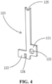
- one of the busbar bodies 120 located outermost in the preset direction is provided with a wiring portion 121 (i.e., the busbar body shown in Fig. 4 ), the wiring portion 121 extending from this busbar body 120 in a direction away from the others of the busbar bodies 120, and the busbar bracket 11 is provided with a positioning slot 113 for snapping to the wiring portion 121.
- the wiring portion 121 refers to a portion provided on the busbar body 120 that is used for electrical connection with the outside, and since the busbar body 120 herein is used in an occasion of connecting the plurality of battery cell units 21 in the battery cell assembly 20 in series, the wiring portion 121 is provided on one of the busbar bodies 120 located outermost in the preset direction, and the positioning slot 113 refers to a groove structure provided on the busbar bracket 11 for snapping to the wiring portion 121.
- connection basis and sufficient connection space can be provided for electrical connection of the battery cell assembly 20 to the outside.
- the wiring portion 121 is provided with a through hole 122.
- the through hole 122 refers to a via hole provided on the wiring portion 121, and by providing the through hole 122 on the wiring portion 121, the positioning of the external connecting component can be facilitated.
- each of the busbar bodies 120 is further provided with a snap-fit portion 123, the snap-fit portion 123 of each of the busbar bodies 120 being bent and extended towards the preset direction (the direction indicated by the arrow X in Fig. 3 ) from the busbar body 120, and the snap-fit portion 123 of each of the busbar bodies 120 being provided with a positioning notch 124, and the busbar bracket 11 is provided with a clamping block 114 for insertion into the positioning notch 124.
- the snap-fit portion 123 refers to a portion of the busbar body 120 that is snap-fit to the busbar bracket 11, and the positioning notch 124 refers to a notch structure provided on the busbar body 120.
- each busbar body 120 and the busbar bracket 11 can be realized, which is conducive to the positioning of the busbar body 120 on the busbar bracket 11.
- the clamping block 114 on the busbar bracket 11 is inserted into the positioning notch 124 on the busbar body 120, so that the busbar body 120 is snap onto the busbar bracket 11.
- the busbar bracket 11 is provided with a plurality of hot-melt posts 115 corresponding one-to-one with the plurality of busbar bodies 120, each of the busbar bodies 120 being provided with a groove 125 surrounding a corresponding one of the hot-melt posts 115, and each of the hot-melt posts 115 fixing and connecting a corresponding one of the busbar bodies 120 to the busbar bracket 11 through hot-melting.
- the hot-melt post 115 is a post provided on the busbar bracket 11, which can be hot-melted into a mushroom shape to function to fix the busbar body 120 provided surrounding the hot-melt post 115.
- the head of the hot-melt post 115 is formed in the shape of a mushroom, so that the busbar body 120 provided surrounding the hot-melt post 115 can be prevented from being detached from the busbar bracket 11, and together with the clamping block 114, it functions to fix and connect the busbar body 120 to the busbar bracket 11.
- the clamping block 114 can prevent the busbar body 120 from detaching from the lower part of the drawing surface of Fig. 3
- the hot-melt post 115 can prevent the busbar body 120 from detaching from the upper part of the drawing surface of Fig. 3
- both of them can prevent the reflux body 120 from detaching from the left and right directions of the drawing surface of Fig. 3 , and thus function to fix the busbar body 120 securely to the busbar bracket 11.
- the busbar body 120 When connecting the busbar body 120 to the busbar bracket 11, the busbar body 120 is affixed to the busbar bracket 11 along a direction directly facing the busbar bracket 11, so that the clamping block 114 on the busbar bracket 11 is inserted into the positioning notch 124 on the busbar body 120 and the groove 125 on the busbar body 120 is made to surround the hot-melt post 115 on the busbar bracket 11, and then the hot-melt post 115 is hot-melted to fix the busbar body 120 to the busbar bracket 11.
- the busbar bracket 11 is further provided with a plurality of blocking plates 116 distributed along the preset direction, each of the blocking plates 116 being located between the snap-fit portions 123 of two adjacent ones of the busbar bodies 120.
- the blocking plate 116 can function to insulate and block two adjacent busbar bodies 120 to ensure that the two adjacent busbar bodies 120 are in an insulated state.
- the busbar assembly 10 may be mounted to the support tool 30 first, and then the battery cell assembly 20 may be lowered until the tabs 210 of the battery cell assembly 20 are inserted into the first notches 112 on the busbar bracket 11.
- the busbar bracket 11 is further provided with a plurality of guide portions 117 and a plurality of second notches 118 alternately distributed along the preset direction, the plurality of second notches 118 and the plurality of first notches 112 being located at two opposite sides of the busbar bracket 11, and the plurality of guide portions 117 protruding towards a side far from the busbar 12.
- the busbar bracket 11 being further provided with a plurality of guide portions 117 and a plurality of second notches 118 alternately distributed along the preset direction means that the plurality of second notches 118 provided on the busbar bracket 11 are distributed along the same direction, two adjacent second notches 118 have a spacing therebetween, and adjacent to each of the second notches 118 is one guide portion 117, wherein the second notches 118 are notches for providing guiding for the busbar assembly 10 when it is mounted to the support tool, and the plurality of second notches 118 are distributed in the same direction as the distribution direction of the plurality of first notches 112, also in the direction shown by arrow X in Fig. 3 .
- the plurality of second notches 118 and the plurality of first notches 112 being located at two opposite sides of the busbar bracket 11 means that the second notches 118 are opened in a direction opposite to the opening direction of the first notches 112. As shown in Fig. 3 , the first notches 112 are opened from the top to the bottom of the busbar bracket 11 in Fig. 3 , whereas the second notches 118 are opened from the bottom to the top of the busbar bracket 11 in Fig. 3 .
- the second notches 118 and the guide portions 117 provided on the busbar 12, as shown in Figs. 7 and 8 , can function to guide the mounting of the busbar assembly 10 to the support tool 10, thereby facilitating the easy mounting of the busbar assembly 10 to the support tool 30, so that support posts 31 on the support tool 30 can be inserted along the second notches 118.
- the support posts 31 provided on the support tool 30 can withstand the pressure from the welding tip of the welding gun during the process of welding the tabs 210 of the battery cell assembly 20.
- the support tool 30 is a rectangular flat plate, and the support tool 30 is provided with recessed regions on two opposite sides to position busbar brackets 11 to be mounted, and at the same time, the recessed region of the support tool 30 is provided with a row of support posts 31, wherein the support post 31 may be inserted along the second notch 118 between two adjacent guide portions 117 when the busbar bracket 11 is mounted to the support tool 30 until the support post 31 abuts against the abutting portion 111 of the busbar bracket 11, then the assembly of the battery cell assembly 20 and the busbar assembly 10 is carried out and, after welding of the tabs 210 is completed, the battery cell assembly 20 and the busbar assembly 10 that have been assembled are removed from the support tool 30.
- Fig. 9 illustrates a structure in which the tabs 210 of the battery cell assembly 20 are gradually lowered and inserted into the busbar bracket 11
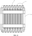
- Figs. 10 and 11 illustrate a front-view structure and a top-view structure, respectively, after completion of welding of the tabs 210 of the battery cell assembly 20 to the busbar body 120
- Fig. 10 and 11 illustrate a front-view structure and a top-view structure, respectively, after completion of welding of the tabs 210 of the battery cell assembly 20 to the busbar body 120
- the 12 illustrates the space (the region shown in rectangular box C) that exists between the busbar bracket 11 and the battery cell unit 21, wherein the space is the space occupied by the support post 31 on the support tool 30 when the battery cell assembly 20 with the busbar assembly 10 assembled is removed from the support tool 30, so as to withstand the pressure from the welding tip of the welding gun by the support post 31 during the process of welding of the tabs 210 of the battery cell assembly 20 to the busbar body 120.
- the busbar bracket 11 is provided with a positioning hole 119 (shown in Fig. 2 ) on a side close to the plurality of second notches 118.
- the positioning hole 119 is used to mate with the positioning post 32 on the support tool 30 to function to position the busbar bracket 11 when the busbar assembly 10 is mounted to the support tool 30.
- the busbar assembly 10 comprises a busbar bracket 11 and a busbar 12, wherein the busbar bracket 11 is provided with a plurality of abutting portions 111 and a plurality of first notches 112 alternately distributed along a preset direction, each of the first notches 112 being used for insertion of a tab 210 of the battery cell assembly 20; the busbar bracket 11 is further provided with a plurality of guide portions 117 and a plurality of second notches 118 alternately distributed along the preset direction, the plurality of second notches 118 and the plurality of first notches 112 being located at two opposite sides of the busbar bracket 11, and the plurality of guide portions 117 protruding towards a side far from the busbar 12; and the busbar 12 comprises a plurality of busbar bodies 120 spaced apart from each other, wherein each busbar body 120 is connected to one of the abutting portions 111, every two of the busbar bodies 120 are spaced apart from each other by one of the abutting
- Embodiments of the present application further provide a battery, comprising: a battery cell assembly 20; and busbar assemblies 10 described in the above embodiments, two busbar assemblies 10 being provided oppositely on two sides of the battery cell assembly 20, wherein tabs 210 on one side of the battery cell assembly 20 are inserted into the first notches 112 on the busbar bracket 11 of one of the busbar assemblies 10 and are electrically connected to the busbar 12 of that busbar assembly 10, and tabs 210 on the other side of the battery cell assembly 20 are inserted into the first notches 112 on the busbar bracket 11 of the other one of the busbar assemblies 10 and are electrically connected to the busbar 12 of that busbar assembly 10.
- the assembler can clearly observe the matching situation of the tabs 210 of the battery cell assembly 20 with the first notches 112, as well as the degree of deviation between the two, thereby enabling a higher degree of visualization of the assembly process of the busbar assembly 10 with the battery cell assembly 20, which is conducive to the real-time adjustments made by the assembler and reduces the difficulty in the assembly process.
- Embodiments of the present application further provide an electrical apparatus, the electrical apparatus using the battery in the above embodiments as the power source.
- the electrical apparatus provided in embodiments of the present application may be, but is not limited to, a mobile phone, a tablet, a laptop, an electric toy, an electric tool, a battery vehicle, an electric vehicle, a ship, a spacecraft, and so on.
- the electric toy may include a stationary or mobile electric toy, for example, a game console, an electric car toy, an electric ship toy, and an electric aircraft toy, and the like
- the spacecraft may include an aircraft, a rocket, a space shuttle and a spaceship, and the like.
Landscapes
- Chemical & Material Sciences (AREA)
- Chemical Kinetics & Catalysis (AREA)
- Electrochemistry (AREA)
- General Chemical & Material Sciences (AREA)
- Inorganic Chemistry (AREA)
- Battery Mounting, Suspending (AREA)
- Connection Of Batteries Or Terminals (AREA)
Abstract
Description
- The present application claims priority to
Chinese patent application No. 202123006685.5, filed with the China National Intellectual Property Administration on December 1, 2021 - The present application relates to the technical field of battery production, and in particular, to a busbar assembly, a battery, and an electrical apparatus.
- The busbar assembly, as an important component in the battery, functions to connect a plurality of battery cell units together in the battery, and compared to the cable connection form, the busbar in the busbar assembly has a larger contact area, and the connection of the plurality of battery cell units through the busbar can reduce the temperature rise of the battery.
- However, the present busbar assembly, when assembled with the battery cell assembly, is more difficult to assemble because the line of sight is obstructed at the tabs of the plurality of battery cell units, and the assembler is unable to confirm that the tab of each battery cell unit can accurately pass through the busbar assembly.
- One of the objectives of embodiments of the present application is to provide a busbar assembly, a battery, and an electrical apparatus, including, but not limited to, solving a problem of difficulty in assembling the busbar assembly with the battery cell.
- The technical solution that embodiments of the present application adopts is as follows:
In a first aspect, a busbar assembly is provided, comprising a busbar bracket and a busbar, wherein the busbar bracket is provided with a plurality of abutting portions and a plurality of first notches alternately distributed along a preset direction, each of the first notches being used for insertion of a tab of a battery cell assembly; and the busbar is connected to at least part of the abutting portions and used for electrical connection with tabs inserted into the first notches. - By the plurality of first notches provided on the busbar bracket, the busbar assembly provided in an implementation of the present application can function to guide the tabs of the battery cell assembly during assembly of the battery cell assembly so that the tab of each battery cell unit in the battery cell assembly can be smoothly inserted into the first notches and be electrically connected with the busbar connected to the abutting portion. Therefore, during the process of inserting the tabs of the battery cell assembly into the first notches, the assembler can clearly observe the matching situation of the tabs of the battery cell assembly with the first notches, as well as the degree of deviation between the two, thereby enabling a higher degree of visualization of the assembly process of the busbar assembly with the battery cell assembly, which is conducive to the real-time adjustments made by the assembler and reduces the difficulty in the assembly process.
- In an embodiment, the busbar comprises a plurality of busbar bodies spaced apart from each other, every two adjacent ones of the busbar bodies being spaced apart from each other by one of the abutting portions, and each of the busbar bodies being used for electrically connecting tabs inserted into the first notches adjacent thereto.
- Embodiments of the present application, by a plurality of busbar bodies spaced apart from each other, can implement series connection between a plurality of battery cell units.
- In an embodiment, one of the busbar bodies located outermost in the preset direction is provided with a wiring portion extending from the busbar body in a direction away from the others of the busbar bodies, and the busbar bracket is provided with a positioning slot for snapping to the wiring portion.
- Embodiments of the present application, by the provision of the wiring portion, can provide a basis for electrical connection with the outside.
- In an embodiment, the wiring portion is provided with a through hole.
- Embodiments of the present application, by the provision of the through hole, can position the external electrical connecting component.
- In an embodiment, each of the busbar bodies are further provided with a snap-fit portion, the snap-fit portion of each of the busbar bodies being bent and extended towards the preset direction from the busbar body, and being provided with a positioning notch, and the busbar bracket is provided with a clamping block for insertion into the positioning notch.
- Embodiments of the present application, by the provision of the snap-fit portion on the busbar body and the clamping block on the busbar bracket, can snap the snap-fit portion of the busbar body into the clamping block on the busbar bracket, so as to implement the snap-fit between the two.
- In an embodiment, the busbar bracket is provided with a plurality of hot-melt posts corresponding one-to-one with the plurality of busbar bodies, each of the busbar bodies being provided with a groove surrounding a corresponding one of the hot-melt posts, and each of the hot-melt posts fixing and connecting a corresponding one of the busbar bodies to the busbar bracket through hot-melting.
- Embodiments of the present application, by hot-melting of the hot-melt post, can implement the fixing connection between the busbar body and the busbar bracket.
- In an embodiment, the busbar bracket is provided with a plurality of hot-melt posts corresponding one-to-one with the plurality of busbar bodies, each of the busbar bodies being provided with a via hole surrounding a corresponding one of the hot-melt posts, and each of the hot-melt posts fixing and connecting a corresponding one of the busbar bodies to the busbar bracket through hot-melting.
- By hot-melting of the hot-melt post, embodiments of the present application can implement the fixing connection between the busbar body and the busbar bracket.
- In an embodiment, the busbar bracket is further provided with a plurality of blocking plates distributed along the preset direction, each of the blocking plates being located between the snap-fit portions of two adjacent ones of the busbar bodies.
- Embodiments of the present application, by the provision of the blocking plate, can function to insulate and block two adjacent busbar bodies.
- In an embodiment, the busbar bracket is further provided with a plurality of guide portions and a plurality of second notches alternately distributed along the preset direction, the plurality of second notches and the plurality of first notches being located at two opposite sides of the busbar bracket, and the plurality of guide portions protruding towards a side far from the busbar.
- Embodiments of the present application, by the provision of the second notches, can function to guide the insertion of the support posts on the support tool when the busbar assembly is mounted to the support tool.
- In an embodiment, the busbar bracket is provided with a positioning hole on a side close to the plurality of second notches.
- Embodiments of the present application, by the provision of the positioning hole, can function to guide the mounting of the busbar bracket to the support tool.
- In a second aspect, a battery is provided, comprising: a battery cell assembly; and busbar assemblies described above, two busbar assemblies being provided oppositely on two sides of the battery cell assembly, wherein tabs on one side of the battery cell assembly are inserted into the first notches on the busbar bracket of one of the busbar assemblies and are electrically connected to the busbar of that busbar assembly, and tabs on the other side of the battery cell assembly are inserted into the first notches on the busbar bracket of the other one of the busbar assemblies and are electrically connected to the busbar of that busbar assembly.
- In an embodiment, the battery cell assembly comprises a plurality of battery cell units arranged, two adjacent ones of the battery cell units being provided inversely so that a positive tab of one of the battery cell units is located on the same side of the battery cell assembly as a negative tab of the other one of the battery cell units, whereby the plurality of battery cell units of the battery cell assembly are connected in series.
- By the inverse provision of two adjacent battery cell units, embodiments of the present application enable the two adjacent battery cell units to be connected in series when the tabs of the battery cell units are electrically connected to the busbar, so as to connect all the battery cell units in series all the way down.
- In an embodiment, the battery cell assembly comprises a plurality of battery cell units arranged, the plurality of battery cell units of the battery cell assembly being connected in series or in parallel.
- In a third aspect, an electrical apparatus is provided, comprising a battery described above.
- In an embodiment, the electrical apparatus is one of a mobile phone, a tablet, a laptop, an electric toy, an electric tool, a battery vehicle, an electric car, a ship or a spacecraft.
- The busbar assembly, the battery and the electrical apparatus provided in implementations of the present application have the following beneficial effects: with the plurality of first notches provided on the busbar bracket, they can function to guide the tabs of the battery cell assembly during assembly with the battery cell assembly, so that the tab of each battery cell unit in the battery cell assembly can be smoothly inserted into the first notches and be electrically connected with the busbar connected to the abutting portion; therefore, during the process of inserting the tabs of the battery cell assembly into the first notches, the assembler can clearly observe the matching situation of the tabs of the battery cell assembly with the first notches, as well as the degree of deviation between the two, thereby enabling a higher degree of visualization of the assembly process of the busbar assembly with the battery cell assembly, which is conducive to the real-time adjustments made by the assembler and reduces the difficulty in the assembly process.
- In order to more clearly illustrate the technical solutions in embodiments of the present application, the accompanying drawings that need to be used in the description of the embodiments or exemplary techniques will be briefly introduced below, and it will be apparent that the accompanying drawings in the following description are only some of the embodiments of the present application, and that other accompanying drawings can be obtained based on these drawings for a person of ordinary skill in the art, without any creative labor.
-
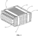
Fig. 1 is a three-dimensional structural schematic diagram of a battery cell assembly according to embodiments of the present application; -
Fig. 2 is a three-dimensional structural schematic diagram of a busbar assembly according to embodiments of the present application; -
Fig. 3 is a front-view structural schematic diagram of a busbar bracket according to embodiments of the present application; -
Fig. 4 is a three-dimensional structural schematic diagram of a busbar body when it is provided with a wiring portion according to embodiments of the present application; -
Fig. 5 is a three-dimensional structural schematic diagram of a busbar body when it is not provided with a wiring portion according to embodiments of the present application; -
Fig. 6 is an exploded structural schematic diagram of a battery cell assembly when it is assembled with a busbar assembly according to embodiments of the present application; -
Fig. 7 is an exploded structural schematic diagram of a busbar assembly when it is mounted to a support tool according to embodiments of the present application; -
Fig. 8 is an enlarged structural schematic diagram of part A inFig. 7 ; -
Fig. 9 is a structural schematic diagram of the battery cell assembly and the busbar assembly when they are in an assembly process according to embodiments of the present application; -
Fig. 10 is a front-view structural schematic diagram of the battery cell assembly and the busbar assembly after completion of assembly according to embodiments of the present application; -
Fig. 11 is a top-view structural schematic diagram of the battery cell assembly and the busbar assembly after completion of assembly according to embodiments of the present application; andFig. 12 is an enlarged structural schematic diagram of part B inFig. 11 . -
- 10, busbar assembly; 11, busbar bracket; 111, abutting portion; 112, first notch; 113, positioning slot; 114, clamping block; 115, hot-melt post; 116, blocking plate; 117, guide portion; 118, second notch; 119, positioning hole; 12, busbar; 120, busbar body; 121, wiring portion; 122, through hole; 123, snap-fit portion; 124, positioning notch; 125, groove;
- 20, battery cell assembly; 21, battery cell unit; 210, tab; 22, end plate; 23, strap;
- 30, support tool; 31, support post; 32, positioning post.
- In order to make the objectives, technical solutions and advantages of the present application clearer and more understandable, the present application is described in further detail hereinafter in conjunction with the accompanying drawings and embodiments. It should be understood that the specific embodiments described herein are only for explaining the present invention and are not intended to limit the present application. Unless otherwise defined, all technical and scientific terms used herein have the same meaning as commonly understood by those skilled in the art belonging to the technical field of the present application; the terms used herein are intended only for the purpose of describing specific embodiments and are not intended to limit the present application. Reference herein to "an embodiment" means that a particular feature, structure, or characteristic described in connection with the embodiment can be included in at least one embodiment of the present application. The appearance of this phrase in various places in the specification does not necessarily refer to the same embodiment, nor is it a separate or alternative embodiment that is mutually exclusive with other embodiments. It is explicitly and implicitly understood by those skilled in the art that the embodiments described herein may be combined with other embodiments. It is to be noted that the terms "comprise/include" and "have" and any variations thereof in the specification and the claims of the present application and in the description of drawings above are intended to cover non-exclusive inclusion.
- The term "and/or" is only an association relationship for describing associated objects, which indicates that there may be three relationships, for example A and/or B may represent three situations: A exists alone, both A and B exist, and B exists alone. In addition, the character "/" herein generally means that the associated objects before and after it are in an "or" relationship.
- When a component is described to be "fixed to", "mounted on" or " provided on" another component, it may be directly on the another component or indirectly on that another component. When a component is described to be "connected" to another component, it may be directly or indirectly connected to that another component, either fixedly connected, detachably connected or integrated as a whole; either mechanically connected or electrically connected; either directly connected or indirectly connected through an intermediate medium; either in an internal communication between the two elements or in a mutual interaction relationship between the two elements.
- The orientation or position relationship indicated by the terms "center", "longitudinal", "transverse", "length", "width", "thickness", "upper", "lower", "front", "back", "left", "right", "vertical", "horizontal", "top", "bottom", "inner", "outer", "clockwise", "counterclockwise", "axial", "radial", "circumferential", etc., are based on the orientation or position relationship shown in the drawings and are intended to facilitate the description only, rather than indicating or implying that the apparatus or element referred to must have a particular orientation or be constructed and operated in a particular orientation, and therefore are not to be interpreted as limitations on the present application. For those of ordinary skill in the art, the specific meanings of the above terms can be understood according to specific situations.
- Terms "first" and "second" are used only for descriptive purposes and are not to be understood as indicating or implying relative importance or implicitly specifying the number of technical features. The meaning of "a plurality of is two or more, unless otherwise explicitly and specifically defined. Similarly, "a plurality of groups" means two or more groups (including two groups), and "a plurality of plates" means two or more plates (including two plates).
- In order to illustrate the technical solutions provided in the present application, a detailed description is given below in conjunction with specific accompanying drawings and embodiments of the present application.
- With the rapid development of new energy sources, batteries are more and more widely used. In order to ensure that the battery has sufficient energy density in the application, as shown in
Fig. 1 , a plurality ofbattery cell units 21 are usually connected in series or in parallel to form abattery cell assembly 20, wherein thebattery cell unit 21 is the smallest energy unit constituting the battery, which is used for realizing the conversion of the chemical energy and the electrical energy. Thebattery cell unit 21 is formed primarily by the winding or laminated placement of a positive electrode plate and a negative electrode plate, and is usually provided with a separator between the positive electrode plate and the negative electrode plate. The portions of the positive electrode plate and the negative electrode plate having an active material form a main body part of thebattery cell unit 21, and the portions of the positive electrode plate and the negative electrode plate not having an active material each form atab 210. During the charging and discharging process of the battery, the positive electrode active material and the negative electrode active material react with the electrolyte solution, and thetabs 210 provide the connection basis for the formation of the current loop. A plurality ofbattery cell units 21 are stacked together in the same direction, withend plates 22 added on both sides, and are bound by astrap 23, and in order to ensure that thebattery cell units 21 will not be easily damaged by pressing of theend plates 22, a layer of cushioning pad can be added to the side of theend plate 22 that is affixed to thebattery cell units 21. - The busbar assembly is used to realize electrical connection between the plurality of
battery cell units 21 in thebattery cell assembly 20, and the busbar assembly comprises a busbar used for the electrical connection function, and a busbar bracket used to support and fix the busbar, wherein the busbar bracket is made of an insulating material, and by means of the busbar, thetabs 210 of the plurality ofbattery cell units 21 can be connected together, and the connection form can be a series connection or a parallel connection. - However, the applicant notes that current busbar assemblies are typically designed to be in the form of via holes and the
battery cell assembly 20 is assembled directly facing the busbar assembly, making it necessary for thetab 210 of eachbattery cell unit 21 to pass through the via holes during the assembly process and then be welded to the busbar. During the actual assembly process by the assembler, as thebattery cell assembly 20 is kept directly facing the busbar assembly, the line of sight will be blocked by the assembly components and thus he or she will not be able to confirm that thetab 210 of eachbattery cell unit 21 can accurately pass through the via hole, and in particular when the number of thebattery cell units 21 is large, the difficulty of the assembly will be substantially increased. - In order to reduce the difficulty in assembling the busbar assembly with the
battery cell assembly 20, the applicant has found that the busbar assembly can be designed in the form of a guide notch, which means that a plurality of notches are opened on the busbar bracket, where each of the notches can ensure the smooth insertion of atab 210 of thebattery cell assembly 20. - After adopting such a busbar assembly, the
battery cell assembly 20 is no longer assembled directly facing the busbar assembly and the assembler only needs to insert thetab 210 of eachbattery cell unit 21 in thebattery cell assembly 20 into the notch of the busbar bracket, and then carry out welding between thetab 210 and the busbar assembly to complete the assembly between the busbar assembly and thebattery cell assembly 20. Since thetab 210 of eachbattery cell unit 21 in thebattery cell assembly 20 and the busbar assembly are staggered from each other during the assembly process, the assembler can always observe the process of gradually inserting thetab 210 of eachbattery cell unit 21 into the notch on the busbar bracket, and can directly perform deviation adjustment, so the degree of visualization during the assembly process is higher, thereby reducing the difficulty of assembly. - The busbar assembly provided in embodiments of the present application can, but is not limited to, be used in lithium-sulfur batteries, sodium-ion batteries, or magnesium-ion batteries.
- As shown in
Figs. 2 and3 , thebusbar assembly 10 provided in embodiments of the present application comprises abusbar bracket 11 and abusbar 12, wherein thebusbar bracket 11 is provided with a plurality of abuttingportions 111 and a plurality offirst notches 112 alternately distributed along a preset direction (the direction indicated by arrow X inFig. 3 ), each of thefirst notches 112 being used for insertion of atab 210 of abattery cell assembly 20; and thebusbar 12 is connected to at least part of the abuttingportions 111 and used for electrical connection withtabs 210 inserted in thefirst notches 112. - The
busbar bracket 11 is a component for supporting and fixing thebusbar 12, and thebusbar 12 is a component for electrical connection with thetabs 210 of thebattery cell assembly 20. Thebusbar bracket 11 being provided with a plurality of abuttingportions 111 and a plurality offirst notches 112 alternately distributed along a preset direction means that the plurality offirst notches 112 provided on thebusbar bracket 11 are distributed along the same direction, two adjacentfirst notches 112 have a spacing therebetween, and adjacent to each of thefirst notches 112 is one abuttingportion 111, wherein thefirst notches 112 are guide notches for insertion oftabs 210 of thebattery cell assembly 20. - With the plurality of
first notches 112 provided on thebusbar bracket 11, it is possible to function to guide thetabs 210 of thebattery cell assembly 20 during assembly with thebattery cell assembly 20, so that thetab 210 of eachbattery cell unit 21 in thebattery cell assembly 20 can be smoothly inserted into thefirst notches 112 and be electrically connected with thebusbar 12 connected to the abuttingportion 111; therefore, during the process of inserting thetabs 210 of thebattery cell assembly 20 into thefirst notches 112, the assembler can clearly observe the matching situation of thetabs 210 of thebattery cell assembly 20 with thefirst notches 112, as well as the degree of deviation between the two, thereby enabling a higher degree of visualization of the assembly process of thebusbar assembly 10 with thebattery cell assembly 20, which is conducive to the real-time adjustments made by the assembler and reduces the difficulty in the assembly process. - Here, the
busbar 12 may be used in an occasion of connecting a plurality ofbattery cell units 21 in thebattery cell assembly 20 in series, or in an occasion of connecting a plurality ofbattery cell units 21 in thebattery cell assembly 20 in parallel. The specific form of thebusbar assembly 10 is illustrated below with an example in which thebusbar 12 is used in an occasion of connecting a plurality ofbattery cell units 21 in thebattery cell assembly 20 in series. - In some embodiments of the present application, optionally, the
busbar 12 comprises a plurality ofbusbar bodies 120 spaced apart from each other (as shown inFigs. 4 and5 ), every two adjacent ones of thebusbar bodies 120 being spaced apart from each other by one of the abuttingportions 111, and each of thebusbar bodies 120 being used for electrically connectingtabs 210 inserted into thefirst notches 112 adjacent thereto. - The
busbar bodies 120 refer to single entities that form thebusbar 12, and the plurality ofbusbar bodies 120 being spaced apart from each other means that the plurality ofbusbar bodies 120 are in a mutually insulating condition and are not electrically connected together with each other. - By spacing the plurality of
busbar bodies 120 apart from each other, it is possible to enable eachbusbar body 120 to electrically connect the positive tab of onebattery cell unit 21 among two adjacentbattery cell units 21 with the negative tab of the otherbattery cell unit 21 while ensuring that the plurality ofbattery cell units 21 in thebattery cell assembly 20 are connected in series all the way down, thereby realizing the series connection of the plurality ofbattery cell units 21 in thebattery cell assembly 20. - Here, in the
battery cell assembly 20, thetabs 210 of the plurality ofbattery cell units 21 are provided in the form of one positive and one negative, which means that two adjacentbattery cell units 21 are inversely provided so that thepositive tab 210 of one of thebattery cell units 21 is located on the same side of thebattery cell assembly 20 as thenegative tab 210 of the otherbattery cell unit 21. - In some embodiments of the present application, optionally, one of the
busbar bodies 120 located outermost in the preset direction is provided with a wiring portion 121 (i.e., the busbar body shown inFig. 4 ), thewiring portion 121 extending from thisbusbar body 120 in a direction away from the others of thebusbar bodies 120, and thebusbar bracket 11 is provided with apositioning slot 113 for snapping to thewiring portion 121. - The
wiring portion 121 refers to a portion provided on thebusbar body 120 that is used for electrical connection with the outside, and since thebusbar body 120 herein is used in an occasion of connecting the plurality ofbattery cell units 21 in thebattery cell assembly 20 in series, thewiring portion 121 is provided on one of thebusbar bodies 120 located outermost in the preset direction, and thepositioning slot 113 refers to a groove structure provided on thebusbar bracket 11 for snapping to thewiring portion 121. - By providing the
wiring portion 121 on one of thebusbar bodies 120 located outermost in the preset direction, a connection basis and sufficient connection space can be provided for electrical connection of thebattery cell assembly 20 to the outside. - In some embodiments of the present application, optionally, the
wiring portion 121 is provided with a throughhole 122. - The through
hole 122 refers to a via hole provided on thewiring portion 121, and by providing the throughhole 122 on thewiring portion 121, the positioning of the external connecting component can be facilitated. - In some embodiments of the present application, optionally, each of the
busbar bodies 120 is further provided with a snap-fit portion 123, the snap-fit portion 123 of each of thebusbar bodies 120 being bent and extended towards the preset direction (the direction indicated by the arrow X inFig. 3 ) from thebusbar body 120, and the snap-fit portion 123 of each of thebusbar bodies 120 being provided with apositioning notch 124, and thebusbar bracket 11 is provided with aclamping block 114 for insertion into thepositioning notch 124. - The snap-
fit portion 123 refers to a portion of thebusbar body 120 that is snap-fit to thebusbar bracket 11, and thepositioning notch 124 refers to a notch structure provided on thebusbar body 120. - By the provision of the snap-
fit portion 123, snap-fit between eachbusbar body 120 and thebusbar bracket 11 can be realized, which is conducive to the positioning of thebusbar body 120 on thebusbar bracket 11. During the snap-fit between thebusbar body 120 and thebusbar bracket 11, theclamping block 114 on thebusbar bracket 11 is inserted into thepositioning notch 124 on thebusbar body 120, so that thebusbar body 120 is snap onto thebusbar bracket 11. - In some embodiments of the present application, optionally, the
busbar bracket 11 is provided with a plurality of hot-melt posts 115 corresponding one-to-one with the plurality ofbusbar bodies 120, each of thebusbar bodies 120 being provided with agroove 125 surrounding a corresponding one of the hot-melt posts 115, and each of the hot-melt posts 115 fixing and connecting a corresponding one of thebusbar bodies 120 to thebusbar bracket 11 through hot-melting. - The hot-
melt post 115 is a post provided on thebusbar bracket 11, which can be hot-melted into a mushroom shape to function to fix thebusbar body 120 provided surrounding the hot-melt post 115. - By hot-melting the hot-
melt post 115, the head of the hot-melt post 115 is formed in the shape of a mushroom, so that thebusbar body 120 provided surrounding the hot-melt post 115 can be prevented from being detached from thebusbar bracket 11, and together with theclamping block 114, it functions to fix and connect thebusbar body 120 to thebusbar bracket 11. - Among them, the
clamping block 114 can prevent thebusbar body 120 from detaching from the lower part of the drawing surface ofFig. 3 , and the hot-melt post 115 can prevent thebusbar body 120 from detaching from the upper part of the drawing surface ofFig. 3 , and at the same time, both of them can prevent thereflux body 120 from detaching from the left and right directions of the drawing surface ofFig. 3 , and thus function to fix thebusbar body 120 securely to thebusbar bracket 11. - Here, it is also possible to provide a via hole structure surrounding the hot-
melt post 115 on thebusbar body 120, and similarly, to fix and connect thebusbar body 120 to thebusbar bracket 11 after hot-melting the hot-melt post 115. - When connecting the
busbar body 120 to thebusbar bracket 11, thebusbar body 120 is affixed to thebusbar bracket 11 along a direction directly facing thebusbar bracket 11, so that theclamping block 114 on thebusbar bracket 11 is inserted into thepositioning notch 124 on thebusbar body 120 and thegroove 125 on thebusbar body 120 is made to surround the hot-melt post 115 on thebusbar bracket 11, and then the hot-melt post 115 is hot-melted to fix thebusbar body 120 to thebusbar bracket 11. - In some embodiments of the present application, optionally, the
busbar bracket 11 is further provided with a plurality of blockingplates 116 distributed along the preset direction, each of the blockingplates 116 being located between the snap-fit portions 123 of two adjacent ones of thebusbar bodies 120. - The blocking
plate 116 can function to insulate and block twoadjacent busbar bodies 120 to ensure that the twoadjacent busbar bodies 120 are in an insulated state. - During assembly of the
battery cell assembly 20 with thebusbar assembly 10, as shown inFig. 6 , thebusbar assembly 10 may be mounted to thesupport tool 30 first, and then thebattery cell assembly 20 may be lowered until thetabs 210 of thebattery cell assembly 20 are inserted into thefirst notches 112 on thebusbar bracket 11. - To facilitate mounting of the
busbar assembly 10 to thesupport tool 30, in some embodiments of the present application, optionally, thebusbar bracket 11 is further provided with a plurality ofguide portions 117 and a plurality ofsecond notches 118 alternately distributed along the preset direction, the plurality ofsecond notches 118 and the plurality offirst notches 112 being located at two opposite sides of thebusbar bracket 11, and the plurality ofguide portions 117 protruding towards a side far from thebusbar 12. - The
busbar bracket 11 being further provided with a plurality ofguide portions 117 and a plurality ofsecond notches 118 alternately distributed along the preset direction means that the plurality ofsecond notches 118 provided on thebusbar bracket 11 are distributed along the same direction, two adjacentsecond notches 118 have a spacing therebetween, and adjacent to each of thesecond notches 118 is oneguide portion 117, wherein thesecond notches 118 are notches for providing guiding for thebusbar assembly 10 when it is mounted to the support tool, and the plurality ofsecond notches 118 are distributed in the same direction as the distribution direction of the plurality offirst notches 112, also in the direction shown by arrow X inFig. 3 . - The plurality of
second notches 118 and the plurality offirst notches 112 being located at two opposite sides of thebusbar bracket 11 means that thesecond notches 118 are opened in a direction opposite to the opening direction of thefirst notches 112. As shown inFig. 3 , thefirst notches 112 are opened from the top to the bottom of thebusbar bracket 11 inFig. 3 , whereas thesecond notches 118 are opened from the bottom to the top of thebusbar bracket 11 inFig. 3 . - The
second notches 118 and theguide portions 117 provided on thebusbar 12, as shown inFigs. 7 and8 , can function to guide the mounting of thebusbar assembly 10 to thesupport tool 10, thereby facilitating the easy mounting of thebusbar assembly 10 to thesupport tool 30, so that support posts 31 on thesupport tool 30 can be inserted along thesecond notches 118. - In addition, the support posts 31 provided on the
support tool 30 can withstand the pressure from the welding tip of the welding gun during the process of welding thetabs 210 of thebattery cell assembly 20. - As shown in
Fig. 7 , thesupport tool 30 is a rectangular flat plate, and thesupport tool 30 is provided with recessed regions on two opposite sides to positionbusbar brackets 11 to be mounted, and at the same time, the recessed region of thesupport tool 30 is provided with a row of support posts 31, wherein thesupport post 31 may be inserted along thesecond notch 118 between twoadjacent guide portions 117 when thebusbar bracket 11 is mounted to thesupport tool 30 until thesupport post 31 abuts against the abuttingportion 111 of thebusbar bracket 11, then the assembly of thebattery cell assembly 20 and thebusbar assembly 10 is carried out and, after welding of thetabs 210 is completed, thebattery cell assembly 20 and thebusbar assembly 10 that have been assembled are removed from thesupport tool 30. -
Fig. 9 illustrates a structure in which thetabs 210 of thebattery cell assembly 20 are gradually lowered and inserted into thebusbar bracket 11,Figs. 10 and11 illustrate a front-view structure and a top-view structure, respectively, after completion of welding of thetabs 210 of thebattery cell assembly 20 to thebusbar body 120, andFig. 12 illustrates the space (the region shown in rectangular box C) that exists between thebusbar bracket 11 and thebattery cell unit 21, wherein the space is the space occupied by thesupport post 31 on thesupport tool 30 when thebattery cell assembly 20 with thebusbar assembly 10 assembled is removed from thesupport tool 30, so as to withstand the pressure from the welding tip of the welding gun by thesupport post 31 during the process of welding of thetabs 210 of thebattery cell assembly 20 to thebusbar body 120. - In some embodiments of the present application, optionally, the
busbar bracket 11 is provided with a positioning hole 119 (shown inFig. 2 ) on a side close to the plurality ofsecond notches 118. - The
positioning hole 119 is used to mate with thepositioning post 32 on thesupport tool 30 to function to position thebusbar bracket 11 when thebusbar assembly 10 is mounted to thesupport tool 30. - In some embodiments of the present application, the
busbar assembly 10 comprises abusbar bracket 11 and abusbar 12, wherein thebusbar bracket 11 is provided with a plurality of abuttingportions 111 and a plurality offirst notches 112 alternately distributed along a preset direction, each of thefirst notches 112 being used for insertion of atab 210 of thebattery cell assembly 20; thebusbar bracket 11 is further provided with a plurality ofguide portions 117 and a plurality ofsecond notches 118 alternately distributed along the preset direction, the plurality ofsecond notches 118 and the plurality offirst notches 112 being located at two opposite sides of thebusbar bracket 11, and the plurality ofguide portions 117 protruding towards a side far from thebusbar 12; and thebusbar 12 comprises a plurality ofbusbar bodies 120 spaced apart from each other, wherein eachbusbar body 120 is connected to one of the abuttingportions 111, every two of thebusbar bodies 120 are spaced apart from each other by one of the abuttingportions 111, one of thebusbar bodies 120 located outermost in the preset direction is provided with awiring portion 121, and eachbusbar body 120 is fixed with thebusbar bracket 11 through hot-melting. - Embodiments of the present application further provide a battery, comprising: a
battery cell assembly 20; andbusbar assemblies 10 described in the above embodiments, twobusbar assemblies 10 being provided oppositely on two sides of thebattery cell assembly 20, whereintabs 210 on one side of thebattery cell assembly 20 are inserted into thefirst notches 112 on thebusbar bracket 11 of one of thebusbar assemblies 10 and are electrically connected to thebusbar 12 of thatbusbar assembly 10, andtabs 210 on the other side of thebattery cell assembly 20 are inserted into thefirst notches 112 on thebusbar bracket 11 of the other one of thebusbar assemblies 10 and are electrically connected to thebusbar 12 of thatbusbar assembly 10. - During the process of inserting the
tabs 210 of thebattery cell assembly 20 into thefirst notches 112, the assembler can clearly observe the matching situation of thetabs 210 of thebattery cell assembly 20 with thefirst notches 112, as well as the degree of deviation between the two, thereby enabling a higher degree of visualization of the assembly process of thebusbar assembly 10 with thebattery cell assembly 20, which is conducive to the real-time adjustments made by the assembler and reduces the difficulty in the assembly process. - Embodiments of the present application further provide an electrical apparatus, the electrical apparatus using the battery in the above embodiments as the power source. The electrical apparatus provided in embodiments of the present application may be, but is not limited to, a mobile phone, a tablet, a laptop, an electric toy, an electric tool, a battery vehicle, an electric vehicle, a ship, a spacecraft, and so on. Among them, the electric toy may include a stationary or mobile electric toy, for example, a game console, an electric car toy, an electric ship toy, and an electric aircraft toy, and the like, and the spacecraft may include an aircraft, a rocket, a space shuttle and a spaceship, and the like.
- The above are only optional embodiments of the present application and are not intended to limit the present application. For those skilled in the art, the present application may be subject to various modifications and changes. Any modifications, equivalent substitutions, improvements, etc., made within the spirit and principles of the present application shall be included within the scope of the claims of the present application.
Claims (15)
- A busbar assembly, comprising:a busbar bracket provided with a plurality of abutting portions and a plurality of first notches alternately distributed along a preset direction, each of the first notches being used for insertion of a tab of a battery cell assembly; anda busbar connected to at least part of the abutting portions and used for electrical connection with tabs inserted into the first notches.
- The busbar assembly according to claim 1, wherein:
the busbar comprises a plurality of busbar bodies spaced apart from each other, every two adjacent ones of the busbar bodies being spaced apart from each other by one of the abutting portions, and each of the busbar bodies being used for electrically connecting tabs inserted into the first notches adjacent thereto. - The busbar assembly according to claim 2, wherein:
one of the busbar bodies located outermost in the preset direction is provided with a wiring portion extending from the busbar body in a direction away from the others of the busbar bodies, and the busbar bracket is provided with a positioning slot for snapping to the wiring portion. - The busbar assembly according to claim 3, wherein:
the wiring portion is provided with a through hole. - The busbar assembly according to any one of claims 2 to 4, wherein:
each of the busbar bodies is further provided with a snap-fit portion, the snap-fit portion of each of the busbar bodies being bent and extended towards the preset direction from the busbar body, and being provided with a positioning notch, and the busbar bracket is provided with a clamping block for insertion into the positioning notch. - The busbar assembly according to claim 5, wherein:
the busbar bracket is further provided with a plurality of blocking plates distributed along the preset direction, each of the blocking plates being located between the snap-fit portions of two adjacent ones of the busbar bodies. - The busbar assembly according to any one of claims 2 to 6, wherein:
the busbar bracket is provided with a plurality of hot-melt posts corresponding one-to-one with the plurality of busbar bodies, each of the busbar bodies being provided with a groove surrounding a corresponding one of the hot-melt posts, and each of the hot-melt posts fixing and connecting a corresponding one of the busbar bodies to the busbar bracket through hot-melting. - The busbar assembly according to any one of claims 2 to 6, wherein:
the busbar bracket is provided with a plurality of hot-melt posts corresponding one-to-one with the plurality of busbar bodies, each of the busbar bodies being provided with a via hole surrounding a corresponding one of the hot-melt posts, and each of the hot-melt posts fixing and connecting a corresponding one of the busbar bodies to the busbar bracket through hot-melting. - The busbar assembly according to any one of claims 1 to 8, wherein:
the busbar bracket is further provided with a plurality of guide portions and a plurality of second notches alternately distributed along the preset direction, the plurality of second notches and the plurality of first notches being located at two opposite sides of the busbar bracket, and the plurality of guide portions protruding towards a side far from the busbar. - The busbar assembly according to claim 9, wherein:
the busbar bracket is provided with a positioning hole on a side close to the plurality of second notches. - A battery, comprising:a battery cell assembly; andbusbar assemblies according to any one of claims 1 to 10, two busbar assemblies being provided oppositely on two sides of the battery cell assembly, wherein tabs on one side of the battery cell assembly are inserted into the first notches on the busbar bracket of one of the busbar assemblies and are electrically connected to the busbar of that busbar assembly, and tabs on the other side of the battery cell assembly are inserted into the first notches on the busbar bracket of the other one of the busbar assemblies and are electrically connected to the busbar of that busbar assembly.
- The battery according to claim 11, wherein the battery cell assembly comprises a plurality of battery cell units arranged, two adjacent ones of the battery cell units being provided inversely so that a positive tab of one of the battery cell units is located on the same side of the battery cell assembly as a negative tab of the other one of the battery cell units, whereby the plurality of battery cell units of the battery cell assembly are connected in series.
- The battery according to claim 11, wherein the battery cell assembly comprises a plurality of battery cell units arranged, the plurality of battery cell units of the battery cell assembly being connected in series or in parallel.
- An electrical apparatus, comprising:
a battery according to any one of claims 11 to 13. - The electrical apparatus according to claim 14, wherein the electrical apparatus is one of a mobile phone, a tablet, a laptop, an electric toy, an electric tool, a battery vehicle, an electric car, a ship or a spacecraft.
Applications Claiming Priority (2)
| Application Number | Priority Date | Filing Date | Title |
|---|---|---|---|
| CN202123006685.5U CN216413212U (en) | 2021-12-01 | 2021-12-01 | Busbar assembly, battery and power consumption device |
| PCT/CN2022/134529 WO2023098598A1 (en) | 2021-12-01 | 2022-11-26 | Busbar assembly, battery and power consuming device |
Publications (2)
| Publication Number | Publication Date |
|---|---|
| EP4354634A1 true EP4354634A1 (en) | 2024-04-17 |
| EP4354634A4 EP4354634A4 (en) | 2025-04-30 |
Family
ID=81304288
Family Applications (1)
| Application Number | Title | Priority Date | Filing Date |
|---|---|---|---|
| EP22900402.3A Pending EP4354634A4 (en) | 2021-12-01 | 2022-11-26 | BUSBAR ARRANGEMENT, BATTERY AND POWER CONSUMPTION DEVICE |
Country Status (4)
| Country | Link |
|---|---|
| US (1) | US20240313362A1 (en) |
| EP (1) | EP4354634A4 (en) |
| CN (1) | CN216413212U (en) |
| WO (1) | WO2023098598A1 (en) |
Families Citing this family (4)
| Publication number | Priority date | Publication date | Assignee | Title |
|---|---|---|---|---|
| CN216413212U (en) * | 2021-12-01 | 2022-04-29 | 宁德时代新能源科技股份有限公司 | Busbar assembly, battery and power consumption device |
| CN114914636A (en) | 2022-05-17 | 2022-08-16 | 中创新航科技股份有限公司 | Battery pack |
| CN114843711B (en) * | 2022-05-23 | 2025-11-07 | 中创新航科技集团股份有限公司 | Busbar assembly and battery pack |
| CN120749361B (en) * | 2025-08-15 | 2025-12-26 | 吉利汽车研究院(宁波)有限公司 | A battery module, a solid-state battery pack and a vehicle |
Family Cites Families (9)
| Publication number | Priority date | Publication date | Assignee | Title |
|---|---|---|---|---|
| KR102018719B1 (en) * | 2016-02-12 | 2019-09-04 | 주식회사 엘지화학 | Busbar for cooling battery cell and battery module using thereof |
| KR102259416B1 (en) * | 2017-12-14 | 2021-06-01 | 주식회사 엘지에너지솔루션 | Battery Module Having Bus bar Assembly |
| KR102317639B1 (en) * | 2018-12-07 | 2021-10-25 | 주식회사 엘지에너지솔루션 | Battery module including insert injection molded busbar |
| CN210325960U (en) * | 2019-07-05 | 2020-04-14 | 恒大新能源科技集团有限公司 | Module utmost point ear supporting structure, battery module and vehicle |
| US11302996B2 (en) * | 2019-08-19 | 2022-04-12 | GM Global Technology Operations LLC | Battery modules with integrated interconnect board assemblies having cell tab comb features |
| CN210006810U (en) * | 2019-08-20 | 2020-01-31 | 宁德时代新能源科技股份有限公司 | battery module |
| CN210897376U (en) * | 2019-09-29 | 2020-06-30 | 东莞新能源科技有限公司 | an energy storage module |
| CN214898762U (en) * | 2020-12-28 | 2021-11-26 | 恒大新能源技术(深圳)有限公司 | Busbar connection structure and battery module |
| CN216413212U (en) * | 2021-12-01 | 2022-04-29 | 宁德时代新能源科技股份有限公司 | Busbar assembly, battery and power consumption device |
-
2021
- 2021-12-01 CN CN202123006685.5U patent/CN216413212U/en active Active
-
2022
- 2022-11-26 EP EP22900402.3A patent/EP4354634A4/en active Pending
- 2022-11-26 WO PCT/CN2022/134529 patent/WO2023098598A1/en not_active Ceased
-
2024
- 2024-05-27 US US18/674,924 patent/US20240313362A1/en active Pending
Also Published As
| Publication number | Publication date |
|---|---|
| US20240313362A1 (en) | 2024-09-19 |
| EP4354634A4 (en) | 2025-04-30 |
| WO2023098598A1 (en) | 2023-06-08 |
| CN216413212U (en) | 2022-04-29 |
Similar Documents
| Publication | Publication Date | Title |
|---|---|---|
| EP4354634A1 (en) | Busbar assembly, battery and power consuming device | |
| KR102754816B1 (en) | Battery pack and vehicle comprising the battery pack | |
| EP2843725B1 (en) | Battery Pack | |
| US9331324B2 (en) | Connector assembly and battery pack having the same | |
| EP2378590B1 (en) | Secondary battery | |
| EP3694015A1 (en) | Battery module having structure facilitating series-parallel connections and battery pack comprising same | |
| EP2450990B1 (en) | Battery module having battery cell holder | |
| US20230121494A1 (en) | Electrode assembly for battery and battery | |
| EP3667764B1 (en) | Battery module | |
| CN111554840B (en) | Battery module and method for manufacturing same | |
| US10236485B2 (en) | Battery module | |
| JP6305732B2 (en) | battery pack | |
| US20150311568A1 (en) | Battery pack | |
| JP2019160736A (en) | Connection module, and power storage module | |
| JP2010092598A (en) | Battery pack | |
| CN220272683U (en) | Connection piece and battery | |
| KR20230157167A (en) | Fastening apparatus of pouch-type battery cell and battery module using the same | |
| CN216597865U (en) | Battery module, battery pack and vehicle | |
| US20250226541A1 (en) | Battery cell assembly and electric device | |
| US20260106332A1 (en) | Busbar assembly | |
| KR101936414B1 (en) | Battery cell having a structure for simultaneous storage and battery pack using the battery cell | |
| CN223771281U (en) | Adapter modules, battery packs, battery bags, and electrical devices | |
| EP4525190A1 (en) | Battery acquisition and connection assembly, battery module, and battery pack | |
| KR102656950B1 (en) | Battery moule and battery pack including the same | |
| EP4492556A1 (en) | Battery pack |
Legal Events
| Date | Code | Title | Description |
|---|---|---|---|
| STAA | Information on the status of an ep patent application or granted ep patent |
Free format text: STATUS: THE INTERNATIONAL PUBLICATION HAS BEEN MADE |
|
| PUAI | Public reference made under article 153(3) epc to a published international application that has entered the european phase |
Free format text: ORIGINAL CODE: 0009012 |
|
| STAA | Information on the status of an ep patent application or granted ep patent |
Free format text: STATUS: REQUEST FOR EXAMINATION WAS MADE |
|
| 17P | Request for examination filed |
Effective date: 20240111 |
|
| AK | Designated contracting states |
Kind code of ref document: A1 Designated state(s): AL AT BE BG CH CY CZ DE DK EE ES FI FR GB GR HR HU IE IS IT LI LT LU LV MC ME MK MT NL NO PL PT RO RS SE SI SK SM TR |
|
| RAP1 | Party data changed (applicant data changed or rights of an application transferred) |
Owner name: CONTEMPORARY AMPEREX TECHNOLOGY(HONG KONG) LIMITED |
|
| REG | Reference to a national code |
Ref country code: DE Ref legal event code: R079 Free format text: PREVIOUS MAIN CLASS: H01M0050507000 Ipc: H01M0050204000 |
|
| RIC1 | Information provided on ipc code assigned before grant |
Ipc: H01M 50/531 20210101ALI20241206BHEP Ipc: H01M 50/522 20210101ALI20241206BHEP Ipc: H01M 50/516 20210101ALI20241206BHEP Ipc: H01M 50/507 20210101ALI20241206BHEP Ipc: H01M 50/505 20210101ALI20241206BHEP Ipc: H01M 50/503 20210101ALI20241206BHEP Ipc: H01M 50/50 20210101ALI20241206BHEP Ipc: H01M 50/204 20210101AFI20241206BHEP |
|
| DAV | Request for validation of the european patent (deleted) | ||
| DAX | Request for extension of the european patent (deleted) | ||
| A4 | Supplementary search report drawn up and despatched |
Effective date: 20250401 |
|
| RIC1 | Information provided on ipc code assigned before grant |
Ipc: H01M 50/531 20210101ALI20250326BHEP Ipc: H01M 50/522 20210101ALI20250326BHEP Ipc: H01M 50/516 20210101ALI20250326BHEP Ipc: H01M 50/507 20210101ALI20250326BHEP Ipc: H01M 50/505 20210101ALI20250326BHEP Ipc: H01M 50/503 20210101ALI20250326BHEP Ipc: H01M 50/50 20210101ALI20250326BHEP Ipc: H01M 50/204 20210101AFI20250326BHEP |