EP4354621A1 - Battery end plate assembly, battery, and electric device - Google Patents
Battery end plate assembly, battery, and electric device Download PDFInfo
- Publication number
- EP4354621A1 EP4354621A1 EP22897502.5A EP22897502A EP4354621A1 EP 4354621 A1 EP4354621 A1 EP 4354621A1 EP 22897502 A EP22897502 A EP 22897502A EP 4354621 A1 EP4354621 A1 EP 4354621A1
- Authority
- EP
- European Patent Office
- Prior art keywords
- end plate
- side plate
- battery
- connecting groove
- plate
- Prior art date
- Legal status (The legal status is an assumption and is not a legal conclusion. Google has not performed a legal analysis and makes no representation as to the accuracy of the status listed.)
- Pending
Links
- 238000003466 welding Methods 0.000 claims description 31
- 238000003756 stirring Methods 0.000 claims description 23
- 239000000463 material Substances 0.000 claims description 17
- 239000003351 stiffener Substances 0.000 claims description 9
- 238000009434 installation Methods 0.000 abstract description 14
- 230000003993 interaction Effects 0.000 abstract description 7
- 230000000694 effects Effects 0.000 abstract description 5
- 238000000034 method Methods 0.000 description 6
- 230000008569 process Effects 0.000 description 6
- 238000010586 diagram Methods 0.000 description 5
- 238000011161 development Methods 0.000 description 4
- 229910052751 metal Inorganic materials 0.000 description 4
- 239000002184 metal Substances 0.000 description 4
- VNWKTOKETHGBQD-UHFFFAOYSA-N methane Chemical compound C VNWKTOKETHGBQD-UHFFFAOYSA-N 0.000 description 4
- 238000004519 manufacturing process Methods 0.000 description 3
- 238000004134 energy conservation Methods 0.000 description 2
- 238000005516 engineering process Methods 0.000 description 2
- 239000002803 fossil fuel Substances 0.000 description 2
- 238000012986 modification Methods 0.000 description 2
- 230000004048 modification Effects 0.000 description 2
- 239000003345 natural gas Substances 0.000 description 2
- 238000011160 research Methods 0.000 description 2
- 229910000838 Al alloy Inorganic materials 0.000 description 1
- JLVVSXFLKOJNIY-UHFFFAOYSA-N Magnesium ion Chemical compound [Mg+2] JLVVSXFLKOJNIY-UHFFFAOYSA-N 0.000 description 1
- FKNQFGJONOIPTF-UHFFFAOYSA-N Sodium cation Chemical compound [Na+] FKNQFGJONOIPTF-UHFFFAOYSA-N 0.000 description 1
- JDZCKJOXGCMJGS-UHFFFAOYSA-N [Li].[S] Chemical compound [Li].[S] JDZCKJOXGCMJGS-UHFFFAOYSA-N 0.000 description 1
- 230000003247 decreasing effect Effects 0.000 description 1
- 230000007547 defect Effects 0.000 description 1
- 238000004146 energy storage Methods 0.000 description 1
- 230000007613 environmental effect Effects 0.000 description 1
- 238000001125 extrusion Methods 0.000 description 1
- 229910001425 magnesium ion Inorganic materials 0.000 description 1
- 239000007769 metal material Substances 0.000 description 1
- 238000012545 processing Methods 0.000 description 1
- 230000009467 reduction Effects 0.000 description 1
- 238000005096 rolling process Methods 0.000 description 1
- 229910001415 sodium ion Inorganic materials 0.000 description 1
Images


Classifications
-
- H—ELECTRICITY
- H01—ELECTRIC ELEMENTS
- H01M—PROCESSES OR MEANS, e.g. BATTERIES, FOR THE DIRECT CONVERSION OF CHEMICAL ENERGY INTO ELECTRICAL ENERGY
- H01M50/00—Constructional details or processes of manufacture of the non-active parts of electrochemical cells other than fuel cells, e.g. hybrid cells
- H01M50/20—Mountings; Secondary casings or frames; Racks, modules or packs; Suspension devices; Shock absorbers; Transport or carrying devices; Holders
- H01M50/262—Mountings; Secondary casings or frames; Racks, modules or packs; Suspension devices; Shock absorbers; Transport or carrying devices; Holders with fastening means, e.g. locks
- H01M50/264—Mountings; Secondary casings or frames; Racks, modules or packs; Suspension devices; Shock absorbers; Transport or carrying devices; Holders with fastening means, e.g. locks for cells or batteries, e.g. straps, tie rods or peripheral frames
-
- H—ELECTRICITY
- H01—ELECTRIC ELEMENTS
- H01M—PROCESSES OR MEANS, e.g. BATTERIES, FOR THE DIRECT CONVERSION OF CHEMICAL ENERGY INTO ELECTRICAL ENERGY
- H01M50/00—Constructional details or processes of manufacture of the non-active parts of electrochemical cells other than fuel cells, e.g. hybrid cells
- H01M50/20—Mountings; Secondary casings or frames; Racks, modules or packs; Suspension devices; Shock absorbers; Transport or carrying devices; Holders
- H01M50/249—Mountings; Secondary casings or frames; Racks, modules or packs; Suspension devices; Shock absorbers; Transport or carrying devices; Holders specially adapted for aircraft or vehicles, e.g. cars or trains
-
- H—ELECTRICITY
- H01—ELECTRIC ELEMENTS
- H01M—PROCESSES OR MEANS, e.g. BATTERIES, FOR THE DIRECT CONVERSION OF CHEMICAL ENERGY INTO ELECTRICAL ENERGY
- H01M50/00—Constructional details or processes of manufacture of the non-active parts of electrochemical cells other than fuel cells, e.g. hybrid cells
- H01M50/20—Mountings; Secondary casings or frames; Racks, modules or packs; Suspension devices; Shock absorbers; Transport or carrying devices; Holders
- H01M50/258—Modular batteries; Casings provided with means for assembling
-
- H—ELECTRICITY
- H01—ELECTRIC ELEMENTS
- H01M—PROCESSES OR MEANS, e.g. BATTERIES, FOR THE DIRECT CONVERSION OF CHEMICAL ENERGY INTO ELECTRICAL ENERGY
- H01M50/00—Constructional details or processes of manufacture of the non-active parts of electrochemical cells other than fuel cells, e.g. hybrid cells
- H01M50/20—Mountings; Secondary casings or frames; Racks, modules or packs; Suspension devices; Shock absorbers; Transport or carrying devices; Holders
- H01M50/289—Mountings; Secondary casings or frames; Racks, modules or packs; Suspension devices; Shock absorbers; Transport or carrying devices; Holders characterised by spacing elements or positioning means within frames, racks or packs
-
- H—ELECTRICITY
- H01—ELECTRIC ELEMENTS
- H01M—PROCESSES OR MEANS, e.g. BATTERIES, FOR THE DIRECT CONVERSION OF CHEMICAL ENERGY INTO ELECTRICAL ENERGY
- H01M50/00—Constructional details or processes of manufacture of the non-active parts of electrochemical cells other than fuel cells, e.g. hybrid cells
- H01M50/20—Mountings; Secondary casings or frames; Racks, modules or packs; Suspension devices; Shock absorbers; Transport or carrying devices; Holders
- H01M50/289—Mountings; Secondary casings or frames; Racks, modules or packs; Suspension devices; Shock absorbers; Transport or carrying devices; Holders characterised by spacing elements or positioning means within frames, racks or packs
- H01M50/291—Mountings; Secondary casings or frames; Racks, modules or packs; Suspension devices; Shock absorbers; Transport or carrying devices; Holders characterised by spacing elements or positioning means within frames, racks or packs characterised by their shape
-
- H—ELECTRICITY
- H01—ELECTRIC ELEMENTS
- H01M—PROCESSES OR MEANS, e.g. BATTERIES, FOR THE DIRECT CONVERSION OF CHEMICAL ENERGY INTO ELECTRICAL ENERGY
- H01M2220/00—Batteries for particular applications
- H01M2220/20—Batteries in motive systems, e.g. vehicle, ship, plane
-
- Y—GENERAL TAGGING OF NEW TECHNOLOGICAL DEVELOPMENTS; GENERAL TAGGING OF CROSS-SECTIONAL TECHNOLOGIES SPANNING OVER SEVERAL SECTIONS OF THE IPC; TECHNICAL SUBJECTS COVERED BY FORMER USPC CROSS-REFERENCE ART COLLECTIONS [XRACs] AND DIGESTS
- Y02—TECHNOLOGIES OR APPLICATIONS FOR MITIGATION OR ADAPTATION AGAINST CLIMATE CHANGE
- Y02E—REDUCTION OF GREENHOUSE GAS [GHG] EMISSIONS, RELATED TO ENERGY GENERATION, TRANSMISSION OR DISTRIBUTION
- Y02E60/00—Enabling technologies; Technologies with a potential or indirect contribution to GHG emissions mitigation
- Y02E60/10—Energy storage using batteries
Definitions
- This application relates to the field of battery technologies, and in particular, to a battery end plate assembly, a battery, and an electric apparatus.
- a traction battery includes a battery end plate assembly for fastening a battery cell.
- a battery end plate assembly typically consists of an end plate and a side plate, where the side plate is a thin plate. Thus, it is inconvenient to install the side plate when connecting the end plate with the side plate.
- this application provides a rolling apparatus and a processing device, so as to solve the problem of installation inconvenience of a side plate of a battery end plate assembly in some cases.
- this application provides a battery end plate assembly including an end plate and a side plate.
- the end plate is provided with a connecting groove on a side for connecting the side plate.
- An end of the side plate is embedded in the connecting groove and abuts against a side wall of the connecting groove.
- the end plate is provided with the connecting groove, the end of the side plate is embedded in the connecting groove, and the side plate is made to abut against the side wall of the connecting groove. Due to the side plate being embedded in and abutting against the connecting groove, an interaction force is present between the connecting groove and the side plate. That means the connecting groove can provide a certain clamping and fixing effect for the side plate to assist a positioning fixture in positioning the side plate, thereby facilitating installation of the side plate and preventing the side plate from tilt during installation.
- depth of the connecting groove is equal to thickness of the side plate.
- the depth of the connection groove is set to be equal to the thickness of the side plate, so that after the side plate is connected to the end plate, the side plate does not exceed the end plate and is at a same horizontal plane as a side, of the end plate, connecting the side plate. This facilitates subsequent automatic fixation of the battery end plate assembly with the connection completed, thereby facilitating production in subsequent processes.
- the end plate and the side plate are connected through friction stir welding.
- the end plate and the side plate being connected through friction stir welding can not only guarantee strength of the connection between the end plate and the side plate, but also eliminate the need to implement the connection with the help of other fixing components and to consume materials such as welding rods. No weld seam protruding from the side of the end plate is generated, so that subsequent automatic assembly is not affected.
- a weld seam generated by welding is arranged along a boundary line on which the end plate and the side plate abut against each other.
- the weld seam is arranged along the boundary line on which the end plate and the side plate abut against each other, so that the end plate and the side plate are stirred and extruded together by a stirring head and a shaft shoulder, making a material of an end plate part mixed into a side plate part to compensate for a thickness loss of the side plate caused by the side plate being stirred and extruded by the stirring head and the shaft shoulder, thereby increasing effective thickness of the weld seam.
- both start and end points of the weld seam generated by welding are located on the end plate.
- Both the start and end points of the weld seam are arranged on the end plate, so that a position with low connection strength at the weld seam is on a side of the end plate with higher strength, preventing the position with low connection strength at the weld seam from being on the side plate or at the joint between the side plate and the end plate, and thus allowing for higher strength of the weld seam at the joint between the side plate and the end plate.
- the end plate and the side plate are made of homogeneous materials.
- the end plate and the side plate being made of homogeneous materials allows for consistent metal fluidity, in plasticization status, of the end plate and the side plate during a friction stir welding process, and thus achieving more thorough mixing.
- the end plate is provided with a recess on a side away from the side plate.
- the side of the end plate being provided with the recess can reduce weight of the end plate, thus allowing for lighter battery end plate assembly and battery.
- the recess is provided with a plurality of stiffeners arranged in a crisscross pattern.
- the recess being provided with stiffeners can guarantee strength of the end plate as much as possible while reducing the weight of the end plate.
- this application further provides a battery including any battery end plate assembly described above.
- this application further provides an electric apparatus including the foregoing battery, the battery being configured to supply electrical energy.
- This application relates to a battery end plate assembly, a battery, and an electric apparatus.
- the end plate is provided with a connecting groove, an end of a side plate is embedded in the connecting groove, and the side plate is made to abut against a side wall of the connecting groove, so that the connecting groove can provide a certain clamping and fixing effect for the side plate to assist a positioning fixture to locate the side plate, thereby facilitating installation of the side plate and preventing the side plate from tilt during installation.
- Depth of the connection groove is set to be equal to thickness of the side plate, so that after the side plate is connected to the end plate, the side plate does not exceed the end plate and is at a same horizontal plane as a side, of the end plate, connecting the side plate, facilitating production in subsequent processes.
- a weld seam generated by friction stir welding is arranged along a boundary line on which the end plate and the side plate abut against each other, so that a material of an end plate part may be mixed into a side plate part, increasing effective thickness of the weld seam.
- Both start and end points of the weld seam are arranged on the end plate, so that strength of the weld seam at the joint between the side plate and the end plate is higher.
- the term "and/or" is only an associative relationship for describing associated objects, indicating that three relationships may be present.
- a and/or B may indicate the following three cases: presence of only A, presence of both A and B, and presence of only B.
- the character "/" in this specification generally indicates an "or" relationship between contextually associated objects.
- a plurality of means more than two (inclusive).
- a plurality of groups means more than two (inclusive) groups
- a plurality of pieces means more than two (inclusive) pieces.
- the terms “mount”, “connect”, “join”, and “fasten” should be understood in their general senses. For example, they may refer to a fixed connection, a detachable connection, or an integral connection, may refer to a mechanical connection or electrical connection, and may refer to a direct connection, an indirect connection via an intermediate medium, or an interaction between two elements. Persons of ordinary skill in the art can understand specific meanings of these terms in this application as appropriate to specific situations.
- a first feature being “on” or “under” a second feature may mean that the first and second features are in direct contact, or the first and second features are in indirect contact through an intermediary.
- the first feature is “above”, “over”, or “on” the second feature may mean that the first feature is directly above or obliquely above the second feature or simply mean that the first feature has a higher level than the second feature.
- That the first feature is "below”, “beneath”, and “under” the second feature may mean that the first feature is directly below or obliquely below the second feature or simply mean that the first feature has a lower level than the second feature.
- Traction batteries have been not only used in energy storage power supply systems such as hydroelectric power plants, thermal power plants, wind power plants, and solar power plants, but also widely used in many other fields including electric transportation tools such as electric bicycles, electric motorcycles, and electric vehicles, military equipment, and aerospace. With the continuous expansion of application fields of traction batteries, market demands for traction batteries are also increasing.
- a battery end plate assembly included in a traction battery suffers from installation inconvenience due to a relatively thin side plate. Specifically, during connection between an end plate and a side plate, the two need to be clamped and fixed separately before they are connected. During fixing of the side plate, because the side plate is relatively thin, it is inconvenient to fix the side plate in a thickness direction of the side plate, and the side plate may bend or even break when subjected to an excessive force in length and width directions.
- a side of the end plate can be provided with a connecting groove for placing the side plate. Before the end plate and the side plate are connected, the side plate is embedded in the connecting groove and is positionally fixed by side walls of the groove, facilitating easy installation of the side plate.
- an end plate is provided with a connecting groove, an end of a side plate is embedded in the connecting groove, and the side plate is made to abut against a side wall of the connecting groove. Due to the side plate being embedded in and abutting against the connecting groove, an interaction force is present between the connecting groove and the side plate. That means the connecting groove can provide a certain clamping and fixing effect for the side plate to facilitate installation of the side plate.
- An embodiment of this application provides an electric apparatus that uses a battery as a power source.
- the electric apparatus may be but is not limited to a mobile phone, a tablet computer, a notebook computer, an electric toy, an electric tool, an electric bicycle, an electric vehicle, a ship, or a spacecraft.
- the electric toy may be a fixed or mobile electric toy, for example, a game console, an electric toy car, an electric toy ship, and an electric toy airplane.
- the spacecraft may include an airplane, a rocket, a space shuttle, a spaceship, and the like.
- the electric apparatus of an embodiment of this application being a vehicle 1000 is used as an example for description of the following embodiments.
- FIG. 1 is a schematic structural diagram of a vehicle 1000 according to some embodiments of this application.
- the vehicle 1000 may be a fossil fuel vehicle, a natural-gas vehicle, or a new energy vehicle, where the new energy vehicle may be a battery electric vehicle, a hybrid electric vehicle, a range-extended vehicle, or the like.
- the vehicle 1000 is provided with a battery 100 inside, where the battery 100 may be disposed at the bottom, front, or rear of the vehicle 1000.
- the battery 100 may be configured to supply power to the vehicle 1000.
- the battery 100 may be used as an operational power source for the vehicle 1000.
- the vehicle 1000 may further include a controller 200 and a motor 300, where the controller 200 is configured to control the battery 100 to supply power to the motor 300, for example, to satisfy power needs of start, navigation, and driving of the vehicle 1000.
- the battery 100 can be used as not only the operational power source for the vehicle 1000 but also a driving power source for the vehicle 1000, replacing or partially replacing fossil fuel or natural gas to provide driving traction for the vehicle 1000.
- FIG. 2 is an exploded view of a battery 100 according to some embodiments of this application.
- the battery 100 includes a box 10, a battery cell 20, and a battery end plate assembly 30 (not shown in FIG. 2 ).
- the battery cell 20 is accommodated in the box 10, and the battery end plate assembly 30 is configured to fasten the battery cell 20.
- the box 10 is configured to provide an accommodating space for the battery cell 20.
- the box 10 may be a variety of structures.
- the box 10 may include a first part 11 and a second part 12. The first part 11 and the second part 12 fit together so that the first part 11 and the second part 12 jointly define a space for accommodating the battery cell 20.
- the second part 12 may be a hollow structure with an opening at one side
- the first part 11 may be a plate-shaped structure
- the first part 11 covers the opening side of the second part 12 for the first part 11 and the second part 12 to jointly define an accommodating space.
- the first part 11 and the second part 12 may both be hollow structures with an opening at one side, and the opening side of the first part 11 is engaged with the opening side of the second part 12.
- the box 10 formed by the first part 11 and the second part 12 may have a variety of shapes, for example, cylinder or cuboid.
- a plurality of battery cells 20 may be provided, and the plurality of battery cells 20 may be connected in series, parallel, or series-parallel, where being connected in series-parallel means a combination of series and parallel connections of the plurality of battery cells 20.
- the plurality of battery cells 20 may be directly connected in series, parallel, or series-parallel, and then an entirety of the plurality of battery cells 20 is accommodated in the box 10; or certainly, the battery 100 may be formed by a plurality of battery cells 20 connected in series, parallel, or series-parallel first to form a battery module and then a plurality of battery modules being connected in series, parallel, or series-parallel to form an entirety which is accommodated in the box 10.
- the battery 100 may further include other structures.
- the battery 100 may further include a busbar configured to implement electrical connection between the plurality of battery cells 20.
- Each battery cell 20 may be a secondary battery or a primary battery, and may be a lithium-sulfur battery, a sodium-ion battery, or a magnesium-ion battery, without being limited thereto.
- the battery cell 20 may be cylindrical, flat, cuboid, or of other shapes.
- FIGs. 3 and 4 show a battery end plate assembly 30 according to an embodiment of this application.
- the battery end plate assembly 30 includes an end plate 31 and a side plate 32.
- the end plate 31 is provided with a connecting groove 311 on a side for connecting the side plate 32, and an end of the side plate 32 is embedded in the connecting groove 311 and abuts against a side wall of the connecting groove 311.
- An end of the side plate 32 abutting against a side wall of the connecting groove 311 means that the side plate 32 is not only in contact with the connecting groove 311, but an interaction force is also present between the side plate 32 and the connecting groove 311.
- the connecting groove 311 accommodates an end of the side plate 32, and a side wall of the connecting groove 311 abuts against the side plate 32. In this way, an interaction force is generated, and a position of the side plate 32 can be limited.
- a connection angle of the end plate 31 and the side plate 32 needs to be considered.
- the end plate 31 and the side plate 32 are connected in a thickness direction of the side plate 32, and size of the connecting groove 311 fits width of the side plate 32, so that the connecting groove 311 can accommodate an end of the side plate 32 in a length direction of the side plate 32.
- the side plate 32 and the end plate 31 are connected in a mutually perpendicular manner.
- the connecting groove 311 is a rectangular groove as shown in FIG. 4 .
- the side on which the side plate 32 and the connecting groove 311 abut against each other may be an inclined surface.
- the side wall of the connecting groove 311 may be set as an inclined surface adapted to the side of the side plate 32.
- the end plate 31 is provided with the connecting groove 311, the end of the side plate 32 is embedded in the connecting groove 311, and the side plate 32 is made to abut against the side wall of the connecting groove 311. Due to the side plate 32 being embedded in and abutting against the connecting groove 311, an interaction force is present between the connecting groove 311 and the side plate 32. That means the connecting groove 311 can provide a certain clamping and fixing effect for the side plate 32 to assist a positioning fixture in positioning the side plate 32, thereby facilitating installation of the side plate 32 and preventing the side plate 32 from tilt during installation.
- depth of the connecting groove 311 is equal to thickness of the side plate 32.
- the depth and the thickness being equal does not mean that the depth and the thickness are limited to be completely the same. There may be a given range of error between the depth and the thickness, and the depth of the connecting groove 311 and the thickness of the side plate 32 are equal within such allowable range of error.
- connection groove 311 is set to be equal to the thickness of the side plate 32, so that after the side plate 32 is connected to the end plate 31, the side plate 32 does not exceed the end plate 31 and is at a same horizontal plane as a side, of the end plate 31, connecting the side plate 32. This facilitates subsequent automatic fixation of the battery end plate assembly 30 with the connection completed, thereby facilitating production in subsequent processes.
- the end plate 31 and the side plate 32 are connected through friction stir welding.
- Friction stir welding indicates that a material being welded is partially melted under heat generated by friction between a welding tool rotating at a high speed and a workpiece. With the welding tool moves forward along the welding interface, a plasticized material flows from the front of the welding tool to the rear under a frictional force generated by rotation of the welding tool. A dense solid-state weld seam 33 is formed under extrusion by the welding tool.
- the end plate 31 and the side plate 32 may be connected in a pattern of thread and so on.
- the end plate 31 and the side plate 32 being connected through friction stir welding can not only guarantee strength of the connection between the end plate 31 and the side plate 32, but also eliminate the need to implement the connection with the help of other fixing components and to consume materials such as welding rods. No weld seam 33 protruding from any side of the end plate 31 is generated, so that subsequent automatic assembly is not affected.
- the weld seam 33 generated by welding is arranged along a boundary line on which the end plate 31 and the side plate 32 abut against each other.
- a stirring head and a shaft shoulder rotate at high speeds, generating heat to plasticize metal at a contact area and to extrude the end plate 31 and the side plate 32, thereby forming the dense weld seam 33.
- the boundary line on which the end plate 31 and the side plate 32 abut against each other indicates the boundary line where surfaces, come into contact and abut against each other, of the end plate 31 and the side plate 32 connect.
- the end plate 31 and the side plate 32 can be plasticized together.
- friction stir welding is performed directly on the side plate 32.
- thickness at the weld seam 33 of the side plate 32 is reduced after the side plate 32 is stirred and extruded by the stirring head and the shaft shoulder, leading to decreased strength.
- the weld seam 33 is arranged along the boundary line on which the end plate 31 and the side plate 32 abut against each other, so that the end plate 31 and the side plate 32 can be stirred and extruded together by the stirring head and the shaft shoulder, making a material of an end plate 31 part be mixed into a side plate 32 part to compensate for a thickness loss of the side plate 32 caused by the side plate being stirred and extruded by the stirring head and the shaft shoulder, thereby increasing effective thickness of the weld seam 33.
- both start and end points of the weld seam 33 generated by welding are located on the end plate 31.
- the start point of the weld seam 33 is where welding starts.
- the end point of the weld seam 33 that is, an end position of the weld seam 33, is where welding ends.
- defects are generated at the start and end positions of the weld seam 33.
- the stirring head is removed from the end plate 31 and the side plate 32, so flowing materials in the end plate 31 and the side plate 32 may not completely fill an original position of the stirring head, resulting in a keyhole.
- the end plate 31 and the side plate 32 are connected in the thickness direction of the side plate 32, the end plate 31 is thicker and stronger than the side plate 32 in the connection direction.
- Both the start and end points of the weld seam 33 are arranged on the end plate 31, so that a position with low connection strength at the weld seam 33 is on a side of the end plate 31 with higher strength, preventing the position with low connection strength at the weld seam 33 from being on the side plate 32 or at the joint between the side plate 32 and the end plate 31, thus allowing for higher strength of the weld seam 33 at the joint between the side plate 32 and the end plate 31.
- the end plate 31 and the side plate 32 are made of homogeneous materials.
- end plate 31 and the side plate 32 are made of a same material, typically a metal material.
- an end plate 31 and a side plate 32 are both aluminum alloy metal.
- the end plate 31 and the side plate 32 being arranged as made of homogeneous materials allows for consistent metal fluidity, in plasticization status, of the end plate 31 and the side plate 32 during a friction stir welding process, and thus achieving more thorough mixing.
- the end plate 31 is provided with a recess 312 on a side away from the side plate 32.
- the side of the end plate 31 away from the side plate 32 indicates a side, of the end plate 31, that is not in contact with the side plate 32, and may be an upper surface, lower surface, or side as shown in FIG. 4 .
- the recess 312 is provided on a side of the end plate 31.
- the recess 312 is recessed on the end plate 31, and one or more recesses 312 may be provided.
- the recess(es) 312 may be arranged on one side of the end plate 31 or on multiple sides of the end plate 31. In these embodiments, the recess(es) 312 are arranged on one side of an end plate 31.
- the side of the end plate 31 being provided with the recess 312 can reduce weight of the end plate 31, thus allowing for lighter battery end plate assembly 30 and battery.
- the recess 312 is provided with a plurality of stiffeners 313 arranged in a crisscross pattern.
- a plurality of stiffeners 313 are provided, and the plurality of stiffeners 313 are arranged inside the recess 312 in a crisscross pattern. In this way, the end plate 31 can be supported in both length and width directions, guaranteeing overall strength of the end plate 31.
- Height of the stiffener 313 may be set as the same as depth of the recess 312, so that the end plate 31 can be supported in the thickness direction as well, thereby guaranteeing strength of the end plate 31.
- the recess 312 being provided with stiffeners 313 can guarantee strength of the end plate 31 as much as possible while reducing the weight of the end plate 31.
- This application further provides a battery 100 including any battery end plate assembly 30 described above.
- This application further provides an electric apparatus including the foregoing battery 100, the battery 100 being configured to supply electrical energy.
- this application provides a battery end plate assembly 30 that includes an end plate 31 and a side plate 32 welded through friction stir welding and made of homogeneous materials.
- the end plate 31 is provided with a connecting groove 311 of which depth is consistent with thickness of the side plate 32.
- the side plate 32 is embedded in the connecting groove 311.
- a weld seam 33 of the end plate 31 and the side plate 32 is arranged along a boundary line on which the end plate 31 and the side plate 32 abut against each other, and both start and end points of the weld seam 33 are located on the end plate 31.
- the arrangements in the foregoing embodiments facilitate easier fixing and limiting of the side plate 32 during a connection process of the end plate 31 and the side plate 32, preventing the side plate 32 from tilt during installation and ensuring higher strength of connection between the end plate 31 and the side plate 32.
- the battery 100 includes the battery end plate assembly 30 in the foregoing embodiments, the battery end plate assembly 30 being configured to fasten a battery cell 20.
- this application provides an electric apparatus, which may specifically be a vehicle 1000, including the battery 100 in the foregoing embodiments, the battery 100 being configured to supply electrical energy.
Landscapes
- Chemical & Material Sciences (AREA)
- Chemical Kinetics & Catalysis (AREA)
- Electrochemistry (AREA)
- General Chemical & Material Sciences (AREA)
- Engineering & Computer Science (AREA)
- Aviation & Aerospace Engineering (AREA)
- Battery Mounting, Suspending (AREA)
Abstract
Description
- This application refers to
Chinese Patent Application No. 202122885566.5, filed on November 23, 2021 - This application relates to the field of battery technologies, and in particular, to a battery end plate assembly, a battery, and an electric apparatus.
- Energy conservation and emission reduction are crucial to the sustainable development of the automobile industry. Electric vehicles, with their advantages in energy conservation and environmental protection, have become an important part of the sustainable development of the automobile industry. For electric vehicles, battery technology is an important factor in connection with their development.
- A traction battery includes a battery end plate assembly for fastening a battery cell. A battery end plate assembly typically consists of an end plate and a side plate, where the side plate is a thin plate. Thus, it is inconvenient to install the side plate when connecting the end plate with the side plate.
- In view of the preceding problem, this application provides a rolling apparatus and a processing device, so as to solve the problem of installation inconvenience of a side plate of a battery end plate assembly in some cases.
- According to a first aspect, this application provides a battery end plate assembly including an end plate and a side plate. The end plate is provided with a connecting groove on a side for connecting the side plate. An end of the side plate is embedded in the connecting groove and abuts against a side wall of the connecting groove.
- In such battery end plate assembly, the end plate is provided with the connecting groove, the end of the side plate is embedded in the connecting groove, and the side plate is made to abut against the side wall of the connecting groove. Due to the side plate being embedded in and abutting against the connecting groove, an interaction force is present between the connecting groove and the side plate. That means the connecting groove can provide a certain clamping and fixing effect for the side plate to assist a positioning fixture in positioning the side plate, thereby facilitating installation of the side plate and preventing the side plate from tilt during installation.
- In a possible embodiment, depth of the connecting groove is equal to thickness of the side plate.
- The depth of the connection groove is set to be equal to the thickness of the side plate, so that after the side plate is connected to the end plate, the side plate does not exceed the end plate and is at a same horizontal plane as a side, of the end plate, connecting the side plate. This facilitates subsequent automatic fixation of the battery end plate assembly with the connection completed, thereby facilitating production in subsequent processes.
- In a possible embodiment, the end plate and the side plate are connected through friction stir welding.
- The end plate and the side plate being connected through friction stir welding can not only guarantee strength of the connection between the end plate and the side plate, but also eliminate the need to implement the connection with the help of other fixing components and to consume materials such as welding rods. No weld seam protruding from the side of the end plate is generated, so that subsequent automatic assembly is not affected.
- In a possible embodiment, a weld seam generated by welding is arranged along a boundary line on which the end plate and the side plate abut against each other.
- The weld seam is arranged along the boundary line on which the end plate and the side plate abut against each other, so that the end plate and the side plate are stirred and extruded together by a stirring head and a shaft shoulder, making a material of an end plate part mixed into a side plate part to compensate for a thickness loss of the side plate caused by the side plate being stirred and extruded by the stirring head and the shaft shoulder, thereby increasing effective thickness of the weld seam.
- In a possible embodiment, both start and end points of the weld seam generated by welding are located on the end plate.
- Both the start and end points of the weld seam are arranged on the end plate, so that a position with low connection strength at the weld seam is on a side of the end plate with higher strength, preventing the position with low connection strength at the weld seam from being on the side plate or at the joint between the side plate and the end plate, and thus allowing for higher strength of the weld seam at the joint between the side plate and the end plate.
- In a possible embodiment, the end plate and the side plate are made of homogeneous materials.
- The end plate and the side plate being made of homogeneous materials allows for consistent metal fluidity, in plasticization status, of the end plate and the side plate during a friction stir welding process, and thus achieving more thorough mixing.
- In a possible embodiment, the end plate is provided with a recess on a side away from the side plate.
- The side of the end plate being provided with the recess can reduce weight of the end plate, thus allowing for lighter battery end plate assembly and battery.
- In a possible embodiment, the recess is provided with a plurality of stiffeners arranged in a crisscross pattern.
- The recess being provided with stiffeners can guarantee strength of the end plate as much as possible while reducing the weight of the end plate.
- According to a second aspect, this application further provides a battery including any battery end plate assembly described above.
- According to a third aspect, this application further provides an electric apparatus including the foregoing battery, the battery being configured to supply electrical energy.
- This application relates to a battery end plate assembly, a battery, and an electric apparatus. The end plate is provided with a connecting groove, an end of a side plate is embedded in the connecting groove, and the side plate is made to abut against a side wall of the connecting groove, so that the connecting groove can provide a certain clamping and fixing effect for the side plate to assist a positioning fixture to locate the side plate, thereby facilitating installation of the side plate and preventing the side plate from tilt during installation. Depth of the connection groove is set to be equal to thickness of the side plate, so that after the side plate is connected to the end plate, the side plate does not exceed the end plate and is at a same horizontal plane as a side, of the end plate, connecting the side plate, facilitating production in subsequent processes. A weld seam generated by friction stir welding is arranged along a boundary line on which the end plate and the side plate abut against each other, so that a material of an end plate part may be mixed into a side plate part, increasing effective thickness of the weld seam. Both start and end points of the weld seam are arranged on the end plate, so that strength of the weld seam at the joint between the side plate and the end plate is higher.
- The foregoing description is merely an overview of the technical solution of this application. For a better understanding of the technical means in this application such that they can be implemented according to the content of the specification, and to make the above and other objectives, features and advantages of this application more obvious and easier to understand, the following describes specific embodiments of this application.
- To describe the technical solutions of embodiments of this application more clearly, the following briefly describes the accompanying drawings required for describing the embodiments of this application. Apparently, the accompanying drawings described below show merely some embodiments of this application, and persons of ordinary skill in the art may still derive other drawings from the accompanying drawings without creative efforts. In the accompanying drawings:
-
FIG. 1 is a schematic structural diagram of a vehicle according to an embodiment of this application; -
FIG. 2 is a schematic structural exploded view of a battery according to an embodiment of this application; -
FIG. 3 is a schematic structural diagram of a battery end plate assembly according to an embodiment of this application; -
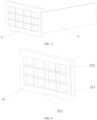
FIG. 4 is a schematic structural diagram of the end plate inFIG. 3 ; -
FIG. 5 is a top cross-sectional view ofFIG. 3 ; and -
FIG. 6 is a schematic structural diagram of the battery end plate assembly inFIG. 3 with connection completed. - Reference signs are as follows:
- 1000. vehicle;
- 100. battery; 200. controller; 300. motor;
- 10. box; 11. first part; 12. second part;
- 20. battery cell;
- 30. battery end plate assembly; 31. end plate; 311. connecting groove; 312. recess; 313. stiffener; 32. side plate; and 33. weld seam.
- The following describes in detail the embodiments of technical solutions of this application with reference to the accompanying drawings. The following embodiments are merely intended for a clearer description of the technical solutions of this application and therefore are used as just examples which do not constitute any limitations on the protection scope of this application.
- Unless otherwise defined, all technical and scientific terms used herein shall have the same meanings as commonly understood by those skilled in the art to which this application relates. The terms used herein are intended to merely describe the specific embodiments rather than to limit this application. The terms "include", "comprise", and "have" and any other variations thereof in the specification, claims and brief description of drawings of this application are intended to cover non-exclusive inclusions.
- In the description of the embodiments of this application, the terms "first", "second", and the like are merely intended to distinguish between different objects, and shall not be understood as any indication or implication of relative importance or any implicit indication of the number, sequence, or primary-secondary relationship of the technical features indicated. In the description of the embodiments of this application, "a plurality of" means at least two unless otherwise specifically stated.
- In this specification, reference to "embodiment" means that specific features, structures or characteristics described with reference to the embodiment may be incorporated in at least one embodiment of this application. The word "embodiment" appearing in various places in the specification does not necessarily refer to the same embodiment or an independent or alternative embodiment that is exclusive of other embodiments. It is explicitly or implicitly understood by persons skilled in the art that the embodiments described herein may be combined with other embodiments.
- In the description of the embodiments of this application, the term "and/or" is only an associative relationship for describing associated objects, indicating that three relationships may be present. For example, A and/or B may indicate the following three cases: presence of only A, presence of both A and B, and presence of only B. In addition, the character "/" in this specification generally indicates an "or" relationship between contextually associated objects.
- In the description of the embodiments of this application, the term "a plurality of" means more than two (inclusive). Similarly, "a plurality of groups" means more than two (inclusive) groups, and "a plurality of pieces" means more than two (inclusive) pieces.
- In the description of the embodiments of this application, the orientations or positional relationships indicated by the technical terms "center", "longitudinal", "transverse", "length", "width", "thickness", "upper", "lower", "front", "rear", "left", "right", "vertical", "horizontal", "top", "bottom", "inside", "outside", "clockwise", "counterclockwise", "axial", " radial", "circumferential", and the like are based on the orientations or positional relationships as shown in the accompanying drawings. These terms are merely for ease and brevity of description of the embodiments of this application rather than indicating or implying that the means or components mentioned must have specific orientations or must be constructed or manipulated according to specific orientations, and therefore shall not be construed as any limitations on embodiments of this application.
- In the description of the embodiments of this application, unless otherwise specified and defined explicitly, the terms "mount", "connect", "join", and "fasten" should be understood in their general senses. For example, they may refer to a fixed connection, a detachable connection, or an integral connection, may refer to a mechanical connection or electrical connection, and may refer to a direct connection, an indirect connection via an intermediate medium, or an interaction between two elements. Persons of ordinary skill in the art can understand specific meanings of these terms in this application as appropriate to specific situations.
- In the description of the embodiments of the present application, unless otherwise clearly specified and defined, a first feature being "on" or "under" a second feature may mean that the first and second features are in direct contact, or the first and second features are in indirect contact through an intermediary. Moreover, that the first feature is "above", "over", or "on" the second feature may mean that the first feature is directly above or obliquely above the second feature or simply mean that the first feature has a higher level than the second feature. That the first feature is "below", "beneath", and "under" the second feature may mean that the first feature is directly below or obliquely below the second feature or simply mean that the first feature has a lower level than the second feature.
- Currently, from the perspective of market development, application of traction batteries is being more extensive. Traction batteries have been not only used in energy storage power supply systems such as hydroelectric power plants, thermal power plants, wind power plants, and solar power plants, but also widely used in many other fields including electric transportation tools such as electric bicycles, electric motorcycles, and electric vehicles, military equipment, and aerospace. With the continuous expansion of application fields of traction batteries, market demands for traction batteries are also increasing.
- The inventors have noticed that a battery end plate assembly included in a traction battery suffers from installation inconvenience due to a relatively thin side plate. Specifically, during connection between an end plate and a side plate, the two need to be clamped and fixed separately before they are connected. During fixing of the side plate, because the side plate is relatively thin, it is inconvenient to fix the side plate in a thickness direction of the side plate, and the side plate may bend or even break when subjected to an excessive force in length and width directions.
- To alleviate the problem of inconvenient installation of the side plate of the battery end plate assembly, the applicant has found through research that a side of the end plate can be provided with a connecting groove for placing the side plate. Before the end plate and the side plate are connected, the side plate is embedded in the connecting groove and is positionally fixed by side walls of the groove, facilitating easy installation of the side plate.
- Based on the above considerations, the inventors, after in-depth research, have designed a battery end plate assembly. In such battery end plate assembly, an end plate is provided with a connecting groove, an end of a side plate is embedded in the connecting groove, and the side plate is made to abut against a side wall of the connecting groove. Due to the side plate being embedded in and abutting against the connecting groove, an interaction force is present between the connecting groove and the side plate. That means the connecting groove can provide a certain clamping and fixing effect for the side plate to facilitate installation of the side plate.
- An embodiment of this application provides an electric apparatus that uses a battery as a power source. The electric apparatus may be but is not limited to a mobile phone, a tablet computer, a notebook computer, an electric toy, an electric tool, an electric bicycle, an electric vehicle, a ship, or a spacecraft. The electric toy may be a fixed or mobile electric toy, for example, a game console, an electric toy car, an electric toy ship, and an electric toy airplane. The spacecraft may include an airplane, a rocket, a space shuttle, a spaceship, and the like.
- For ease of description, the electric apparatus of an embodiment of this application being a
vehicle 1000 is used as an example for description of the following embodiments. - Referring to
FIG. 1, FIG. 1 is a schematic structural diagram of avehicle 1000 according to some embodiments of this application. Thevehicle 1000 may be a fossil fuel vehicle, a natural-gas vehicle, or a new energy vehicle, where the new energy vehicle may be a battery electric vehicle, a hybrid electric vehicle, a range-extended vehicle, or the like. Thevehicle 1000 is provided with abattery 100 inside, where thebattery 100 may be disposed at the bottom, front, or rear of thevehicle 1000. Thebattery 100 may be configured to supply power to thevehicle 1000. For example, thebattery 100 may be used as an operational power source for thevehicle 1000. Thevehicle 1000 may further include acontroller 200 and amotor 300, where thecontroller 200 is configured to control thebattery 100 to supply power to themotor 300, for example, to satisfy power needs of start, navigation, and driving of thevehicle 1000. - In some embodiments of this application, the
battery 100 can be used as not only the operational power source for thevehicle 1000 but also a driving power source for thevehicle 1000, replacing or partially replacing fossil fuel or natural gas to provide driving traction for thevehicle 1000. - Referring to
FIG. 2, FIG. 2 is an exploded view of abattery 100 according to some embodiments of this application. Thebattery 100 includes abox 10, abattery cell 20, and a battery end plate assembly 30 (not shown inFIG. 2 ). Thebattery cell 20 is accommodated in thebox 10, and the batteryend plate assembly 30 is configured to fasten thebattery cell 20. Thebox 10 is configured to provide an accommodating space for thebattery cell 20. Thebox 10 may be a variety of structures. In some embodiments, thebox 10 may include afirst part 11 and asecond part 12. Thefirst part 11 and thesecond part 12 fit together so that thefirst part 11 and thesecond part 12 jointly define a space for accommodating thebattery cell 20. Thesecond part 12 may be a hollow structure with an opening at one side, thefirst part 11 may be a plate-shaped structure, and thefirst part 11 covers the opening side of thesecond part 12 for thefirst part 11 and thesecond part 12 to jointly define an accommodating space. Alternatively, thefirst part 11 and thesecond part 12 may both be hollow structures with an opening at one side, and the opening side of thefirst part 11 is engaged with the opening side of thesecond part 12. Certainly, thebox 10 formed by thefirst part 11 and thesecond part 12 may have a variety of shapes, for example, cylinder or cuboid. - In the
battery 100, a plurality ofbattery cells 20 may be provided, and the plurality ofbattery cells 20 may be connected in series, parallel, or series-parallel, where being connected in series-parallel means a combination of series and parallel connections of the plurality ofbattery cells 20. The plurality ofbattery cells 20 may be directly connected in series, parallel, or series-parallel, and then an entirety of the plurality ofbattery cells 20 is accommodated in thebox 10; or certainly, thebattery 100 may be formed by a plurality ofbattery cells 20 connected in series, parallel, or series-parallel first to form a battery module and then a plurality of battery modules being connected in series, parallel, or series-parallel to form an entirety which is accommodated in thebox 10. Thebattery 100 may further include other structures. For example, thebattery 100 may further include a busbar configured to implement electrical connection between the plurality ofbattery cells 20. - Each
battery cell 20 may be a secondary battery or a primary battery, and may be a lithium-sulfur battery, a sodium-ion battery, or a magnesium-ion battery, without being limited thereto. Thebattery cell 20 may be cylindrical, flat, cuboid, or of other shapes. -
FIGs. 3 and 4 show a batteryend plate assembly 30 according to an embodiment of this application. The batteryend plate assembly 30 includes anend plate 31 and aside plate 32. Theend plate 31 is provided with a connectinggroove 311 on a side for connecting theside plate 32, and an end of theside plate 32 is embedded in the connectinggroove 311 and abuts against a side wall of the connectinggroove 311. - An end of the
side plate 32 abutting against a side wall of the connectinggroove 311 means that theside plate 32 is not only in contact with the connectinggroove 311, but an interaction force is also present between theside plate 32 and the connectinggroove 311. - The connecting
groove 311 accommodates an end of theside plate 32, and a side wall of the connectinggroove 311 abuts against theside plate 32. In this way, an interaction force is generated, and a position of theside plate 32 can be limited. - During arrangement of the connecting
groove 311, a connection angle of theend plate 31 and theside plate 32 needs to be considered. For example, in this embodiment, as shown inFIG. 3 , theend plate 31 and theside plate 32 are connected in a thickness direction of theside plate 32, and size of the connectinggroove 311 fits width of theside plate 32, so that the connectinggroove 311 can accommodate an end of theside plate 32 in a length direction of theside plate 32. Moreover, as shown inFIG. 3 , theside plate 32 and theend plate 31 are connected in a mutually perpendicular manner. In this case, the connectinggroove 311 is a rectangular groove as shown inFIG. 4 . In some other possible arrangements, the side on which theside plate 32 and the connectinggroove 311 abut against each other may be an inclined surface. In this case, the side wall of the connectinggroove 311 may be set as an inclined surface adapted to the side of theside plate 32. - In such battery
end plate assembly 30, theend plate 31 is provided with the connectinggroove 311, the end of theside plate 32 is embedded in the connectinggroove 311, and theside plate 32 is made to abut against the side wall of the connectinggroove 311. Due to theside plate 32 being embedded in and abutting against the connectinggroove 311, an interaction force is present between the connectinggroove 311 and theside plate 32. That means the connectinggroove 311 can provide a certain clamping and fixing effect for theside plate 32 to assist a positioning fixture in positioning theside plate 32, thereby facilitating installation of theside plate 32 and preventing theside plate 32 from tilt during installation. - Referring to
FIG. 5 , according to some embodiments of this application, depth of the connectinggroove 311 is equal to thickness of theside plate 32. - It can be understood that the depth and the thickness being equal does not mean that the depth and the thickness are limited to be completely the same. There may be a given range of error between the depth and the thickness, and the depth of the connecting
groove 311 and the thickness of theside plate 32 are equal within such allowable range of error. - The depth of the
connection groove 311 is set to be equal to the thickness of theside plate 32, so that after theside plate 32 is connected to theend plate 31, theside plate 32 does not exceed theend plate 31 and is at a same horizontal plane as a side, of theend plate 31, connecting theside plate 32. This facilitates subsequent automatic fixation of the batteryend plate assembly 30 with the connection completed, thereby facilitating production in subsequent processes. - According to some embodiments of this application, the
end plate 31 and theside plate 32 are connected through friction stir welding. - Friction stir welding (Friction Stir Welding, FSW) indicates that a material being welded is partially melted under heat generated by friction between a welding tool rotating at a high speed and a workpiece. With the welding tool moves forward along the welding interface, a plasticized material flows from the front of the welding tool to the rear under a frictional force generated by rotation of the welding tool. A dense solid-
state weld seam 33 is formed under extrusion by the welding tool. - In some other embodiments, the
end plate 31 and theside plate 32 may be connected in a pattern of thread and so on. - The
end plate 31 and theside plate 32 being connected through friction stir welding can not only guarantee strength of the connection between theend plate 31 and theside plate 32, but also eliminate the need to implement the connection with the help of other fixing components and to consume materials such as welding rods. Noweld seam 33 protruding from any side of theend plate 31 is generated, so that subsequent automatic assembly is not affected. - Referring to
FIG. 6 , according to some embodiments of this application, theweld seam 33 generated by welding is arranged along a boundary line on which theend plate 31 and theside plate 32 abut against each other. - During welding of the
end plate 31 and theside plate 32 through friction stir welding, a stirring head and a shaft shoulder rotate at high speeds, generating heat to plasticize metal at a contact area and to extrude theend plate 31 and theside plate 32, thereby forming thedense weld seam 33. - The boundary line on which the
end plate 31 and theside plate 32 abut against each other indicates the boundary line where surfaces, come into contact and abut against each other, of theend plate 31 and theside plate 32 connect. With theweld seam 33 arranged along the boundary line on which theend plate 31 and theside plate 32 abut against each other, theend plate 31 and theside plate 32 can be plasticized together. - In some cases, friction stir welding is performed directly on the
side plate 32. In some cases, due to the relativelythin side plate 32, thickness at theweld seam 33 of theside plate 32 is reduced after theside plate 32 is stirred and extruded by the stirring head and the shaft shoulder, leading to decreased strength. In these embodiments, theweld seam 33 is arranged along the boundary line on which theend plate 31 and theside plate 32 abut against each other, so that theend plate 31 and theside plate 32 can be stirred and extruded together by the stirring head and the shaft shoulder, making a material of anend plate 31 part be mixed into aside plate 32 part to compensate for a thickness loss of theside plate 32 caused by the side plate being stirred and extruded by the stirring head and the shaft shoulder, thereby increasing effective thickness of theweld seam 33. - Referring to
FIG. 6 , according to some embodiments of this application, both start and end points of theweld seam 33 generated by welding are located on theend plate 31. - The start point of the
weld seam 33, that is, a start position of theweld seam 33, is where welding starts. The end point of theweld seam 33, that is, an end position of theweld seam 33, is where welding ends. During welding of theend plate 31 and theside plate 32 through friction stir welding, defects are generated at the start and end positions of theweld seam 33. In detail, at the start position of theweld seam 33 where the stirring head and the shaft shoulder start rotating, rotation speeds and heat generated are relatively low, resulting in poor fluidity of materials of theend plate 31 and theside plate 32, thereby leading to insufficient connection strength. At the end position of theweld seam 33, the stirring head is removed from theend plate 31 and theside plate 32, so flowing materials in theend plate 31 and theside plate 32 may not completely fill an original position of the stirring head, resulting in a keyhole. - Because the
end plate 31 and theside plate 32 are connected in the thickness direction of theside plate 32, theend plate 31 is thicker and stronger than theside plate 32 in the connection direction. Both the start and end points of theweld seam 33 are arranged on theend plate 31, so that a position with low connection strength at theweld seam 33 is on a side of theend plate 31 with higher strength, preventing the position with low connection strength at theweld seam 33 from being on theside plate 32 or at the joint between theside plate 32 and theend plate 31, thus allowing for higher strength of theweld seam 33 at the joint between theside plate 32 and theend plate 31. - According to some embodiments of this application, the
end plate 31 and theside plate 32 are made of homogeneous materials. - Being made of homogeneous materials means that the
end plate 31 and theside plate 32 are made of a same material, typically a metal material. In these embodiments, anend plate 31 and aside plate 32 are both aluminum alloy metal. - The
end plate 31 and theside plate 32 being arranged as made of homogeneous materials allows for consistent metal fluidity, in plasticization status, of theend plate 31 and theside plate 32 during a friction stir welding process, and thus achieving more thorough mixing. - Referring to
FIGs. 4 and5 , according to some embodiments of this application, theend plate 31 is provided with arecess 312 on a side away from theside plate 32. - The side of the
end plate 31 away from theside plate 32 indicates a side, of theend plate 31, that is not in contact with theside plate 32, and may be an upper surface, lower surface, or side as shown inFIG. 4 . In these embodiments, therecess 312 is provided on a side of theend plate 31. - The
recess 312 is recessed on theend plate 31, and one ormore recesses 312 may be provided. The recess(es) 312 may be arranged on one side of theend plate 31 or on multiple sides of theend plate 31. In these embodiments, the recess(es) 312 are arranged on one side of anend plate 31. - The side of the
end plate 31 being provided with therecess 312 can reduce weight of theend plate 31, thus allowing for lighter batteryend plate assembly 30 and battery. - Referring to
FIGs. 4 and5 , according to some embodiments of this application, therecess 312 is provided with a plurality ofstiffeners 313 arranged in a crisscross pattern. - A plurality of
stiffeners 313 are provided, and the plurality ofstiffeners 313 are arranged inside therecess 312 in a crisscross pattern. In this way, theend plate 31 can be supported in both length and width directions, guaranteeing overall strength of theend plate 31. Height of thestiffener 313 may be set as the same as depth of therecess 312, so that theend plate 31 can be supported in the thickness direction as well, thereby guaranteeing strength of theend plate 31. - The
recess 312 being provided withstiffeners 313 can guarantee strength of theend plate 31 as much as possible while reducing the weight of theend plate 31. - This application further provides a
battery 100 including any batteryend plate assembly 30 described above. - This application further provides an electric apparatus including the foregoing
battery 100, thebattery 100 being configured to supply electrical energy. - According to some embodiments of this application, referring to
FIGs. 3 to 6 , this application provides a batteryend plate assembly 30 that includes anend plate 31 and aside plate 32 welded through friction stir welding and made of homogeneous materials. Theend plate 31 is provided with a connectinggroove 311 of which depth is consistent with thickness of theside plate 32. When theend plate 31 and theside plate 32 are connected, theside plate 32 is embedded in the connectinggroove 311. Moreover, aweld seam 33 of theend plate 31 and theside plate 32 is arranged along a boundary line on which theend plate 31 and theside plate 32 abut against each other, and both start and end points of theweld seam 33 are located on theend plate 31. The arrangements in the foregoing embodiments facilitate easier fixing and limiting of theside plate 32 during a connection process of theend plate 31 and theside plate 32, preventing theside plate 32 from tilt during installation and ensuring higher strength of connection between theend plate 31 and theside plate 32. - According to some embodiments of this application, referring to
FIG. 2 , this application provides a battery. Thebattery 100 includes the batteryend plate assembly 30 in the foregoing embodiments, the batteryend plate assembly 30 being configured to fasten abattery cell 20. - According to some embodiments of this application, referring to
FIG. 1 , this application provides an electric apparatus, which may specifically be avehicle 1000, including thebattery 100 in the foregoing embodiments, thebattery 100 being configured to supply electrical energy. - In conclusion, it should be noted that the foregoing embodiments are for description of the technical solutions of this application only rather than for limiting this application. Although this application has been described in detail with reference to the foregoing embodiments, persons of ordinary skill in the art should appreciate that they can still make modifications to the technical solutions described in the embodiments or make equivalent replacements to some or all technical features thereof without departing from the scope of the technical solutions of the embodiments of this application. All such modifications and equivalent replacements shall fall within the scope of claims and specification of this application. In particular, as long as there is no structural conflict, the various technical features mentioned in the embodiments can be combined in any manner. This application is not limited to the specific embodiments disclosed in this specification but includes all technical solutions falling within the scope of the claims.
Claims (10)
- A battery end plate assembly comprising an end plate (31) and a side plate (32), wherein the end plate (31) is provided with a connecting groove (311) on a side for connecting the side plate (32), and an end of the side plate (32) is embedded in the connecting groove (311) and abuts against a side wall of the connecting groove (311).
- The battery end plate assembly according to claim 1, wherein depth of the connecting groove (311) is equal to thickness of the side plate (32).
- The battery end plate assembly according to claim 1 or 2, wherein the end plate (31) and the side plate (32) are connected through friction stir welding.
- The battery end plate assembly according to any one of claims 1 to 3, wherein a weld seam (33) generated by welding is arranged along a boundary line on which the end plate (31) and the side plate (32) abut against each other.
- The battery end plate assembly according to any one of claims 1 to 4, wherein both start and end points of the weld seam (33) generated by welding are located on the end plate (31).
- The battery end plate assembly according to any one of claims 1 to 5, wherein the end plate (31) and the side plate (32) are made of homogeneous materials.
- The battery end plate assembly according to any one of claims 1 to 6, wherein the end plate (31) is provided with a recess (312) on a side away from the side plate (32).
- The battery end plate assembly according to claim 7, wherein the recess (312) is provided with a plurality of stiffeners (313) arranged in a crisscross pattern.
- A battery comprising the battery end plate assembly (30) according to any one of claims 1 to 8.
- An electric apparatus, wherein the electric apparatus comprises the battery (100) according to claim 9, the battery (100) being configured to supply electrical energy.
Applications Claiming Priority (2)
| Application Number | Priority Date | Filing Date | Title |
|---|---|---|---|
| CN202122885566.5U CN216354611U (en) | 2021-11-23 | 2021-11-23 | Battery end plate assembly, battery and power utilization device |
| PCT/CN2022/127172 WO2023093419A1 (en) | 2021-11-23 | 2022-10-25 | Battery end plate assembly, battery, and electric device |
Publications (2)
| Publication Number | Publication Date |
|---|---|
| EP4354621A1 true EP4354621A1 (en) | 2024-04-17 |
| EP4354621A4 EP4354621A4 (en) | 2025-02-26 |
Family
ID=81152481
Family Applications (1)
| Application Number | Title | Priority Date | Filing Date |
|---|---|---|---|
| EP22897502.5A Pending EP4354621A4 (en) | 2021-11-23 | 2022-10-25 | BATTERY END PLATE ASSEMBLY, BATTERY AND ELECTRICAL DEVICE |
Country Status (4)
| Country | Link |
|---|---|
| US (1) | US20240162553A1 (en) |
| EP (1) | EP4354621A4 (en) |
| CN (1) | CN216354611U (en) |
| WO (1) | WO2023093419A1 (en) |
Families Citing this family (1)
| Publication number | Priority date | Publication date | Assignee | Title |
|---|---|---|---|---|
| CN216354611U (en) * | 2021-11-23 | 2022-04-19 | 宁德时代新能源科技股份有限公司 | Battery end plate assembly, battery and power utilization device |
Family Cites Families (11)
| Publication number | Priority date | Publication date | Assignee | Title |
|---|---|---|---|---|
| WO2017052296A1 (en) * | 2015-09-24 | 2017-03-30 | 주식회사 엘지화학 | Battery module |
| CN207719286U (en) * | 2017-12-28 | 2018-08-10 | 宁德时代新能源科技股份有限公司 | Battery modules |
| CN109994666B (en) * | 2017-12-29 | 2020-11-06 | 宁德时代新能源科技股份有限公司 | Composite end plate and battery module |
| KR102353921B1 (en) * | 2018-01-12 | 2022-01-20 | 주식회사 엘지에너지솔루션 | Battery module, battery pack and vehicle comprising the same |
| CN110323376B (en) * | 2018-03-30 | 2020-09-01 | 宁德时代新能源科技股份有限公司 | End plate for battery module and battery module |
| KR102726475B1 (en) * | 2019-03-19 | 2024-11-04 | 주식회사 엘지에너지솔루션 | A battery module having an insulating pad having an extended length, a battery pack and a vehicle comprising the same |
| CN209766482U (en) * | 2019-06-28 | 2019-12-10 | 蜂巢能源科技有限公司 | battery pack components |
| CN210403845U (en) * | 2019-09-19 | 2020-04-24 | 宁德时代新能源科技股份有限公司 | Battery modules, battery packs and vehicles |
| CN212991194U (en) * | 2020-07-28 | 2021-04-16 | 中航锂电(洛阳)有限公司 | Battery box and battery package |
| CN212907944U (en) * | 2020-08-20 | 2021-04-06 | 华霆(合肥)动力技术有限公司 | Battery frame and battery module |
| CN216354611U (en) * | 2021-11-23 | 2022-04-19 | 宁德时代新能源科技股份有限公司 | Battery end plate assembly, battery and power utilization device |
-
2021
- 2021-11-23 CN CN202122885566.5U patent/CN216354611U/en active Active
-
2022
- 2022-10-25 EP EP22897502.5A patent/EP4354621A4/en active Pending
- 2022-10-25 WO PCT/CN2022/127172 patent/WO2023093419A1/en not_active Ceased
-
2024
- 2024-01-25 US US18/422,921 patent/US20240162553A1/en active Pending
Also Published As
| Publication number | Publication date |
|---|---|
| US20240162553A1 (en) | 2024-05-16 |
| EP4354621A4 (en) | 2025-02-26 |
| CN216354611U (en) | 2022-04-19 |
| WO2023093419A1 (en) | 2023-06-01 |
Similar Documents
| Publication | Publication Date | Title |
|---|---|---|
| US20250055069A1 (en) | Thermal management component, battery, and electric apparatus | |
| EP4418427A1 (en) | Battery box body, battery and electrical device | |
| EP4386939A1 (en) | Box body, battery, electric device, and device for preparing battery | |
| US20240162553A1 (en) | Battery end plate assembly, battery, and electric apparatus | |
| EP4383426A1 (en) | Battery pack and electric device | |
| US20240047836A1 (en) | Battery cell, battery, electrical device, and device and method for manufacturing battery cell | |
| CN221849124U (en) | Positioning device and welding equipment | |
| US20240243406A1 (en) | Battery and electrical apparatus | |
| US20240380039A1 (en) | Battery top cover, top cover assembly, battery cell, battery, and power consuming device | |
| EP4730548A1 (en) | Electrode assembly, manufacturing method therefor, battery cell, battery and electrical device | |
| US20240313309A1 (en) | Battery top cover assembly, battery cell, battery, and electric apparatus | |
| US20240243337A1 (en) | Electrode assembly, winding method and device, battery cell, battery, and electric apparatus | |
| US20250260112A1 (en) | Plate assembly, box body, battery, and electric apparatus | |
| EP4468455A1 (en) | Heat dissipation mechanism, battery module and electric device | |
| US20250253498A1 (en) | Battery cell, battery, and electric apparatus | |
| JP2024541004A (en) | Circuit board sampling structure, battery module, battery pack and power consumption device | |
| US20250210779A1 (en) | Box, box assembly, battery, and electric device | |
| US20250096348A1 (en) | Heating apparatus, battery, and electric apparatus | |
| CN221057567U (en) | Battery and lower box thereof, electric equipment and welding tool | |
| EP4456308A1 (en) | Connecting component, battery cell, battery and electric device | |
| US12555862B2 (en) | Installation device, battery, electric device, manufacturing method and manufacturing equipment for battery | |
| EP4276989A1 (en) | Battery and electrical device | |
| WO2023093342A1 (en) | Battery cell and battery | |
| CN220710460U (en) | Cooling assembly, battery and electricity utilization device | |
| CN222126847U (en) | Battery device and electric equipment |
Legal Events
| Date | Code | Title | Description |
|---|---|---|---|
| STAA | Information on the status of an ep patent application or granted ep patent |
Free format text: STATUS: THE INTERNATIONAL PUBLICATION HAS BEEN MADE |
|
| PUAI | Public reference made under article 153(3) epc to a published international application that has entered the european phase |
Free format text: ORIGINAL CODE: 0009012 |
|
| STAA | Information on the status of an ep patent application or granted ep patent |
Free format text: STATUS: REQUEST FOR EXAMINATION WAS MADE |
|
| 17P | Request for examination filed |
Effective date: 20240112 |
|
| AK | Designated contracting states |
Kind code of ref document: A1 Designated state(s): AL AT BE BG CH CY CZ DE DK EE ES FI FR GB GR HR HU IE IS IT LI LT LU LV MC ME MK MT NL NO PL PT RO RS SE SI SK SM TR |
|
| RAP1 | Party data changed (applicant data changed or rights of an application transferred) |
Owner name: CONTEMPORARY AMPEREX TECHNOLOGY(HONG KONG) LIMITED |
|
| A4 | Supplementary search report drawn up and despatched |
Effective date: 20250128 |
|
| DAV | Request for validation of the european patent (deleted) | ||
| DAX | Request for extension of the european patent (deleted) | ||
| RIC1 | Information provided on ipc code assigned before grant |
Ipc: H01M 50/289 20210101AFI20250123BHEP |