EP4354620A2 - Battery pack, vehicle including battery pack, and method for controlling battery pack - Google Patents
Battery pack, vehicle including battery pack, and method for controlling battery pack Download PDFInfo
- Publication number
- EP4354620A2 EP4354620A2 EP24160488.3A EP24160488A EP4354620A2 EP 4354620 A2 EP4354620 A2 EP 4354620A2 EP 24160488 A EP24160488 A EP 24160488A EP 4354620 A2 EP4354620 A2 EP 4354620A2
- Authority
- EP
- European Patent Office
- Prior art keywords
- unit
- battery
- vehicle
- battery pack
- control unit
- Prior art date
- Legal status (The legal status is an assumption and is not a legal conclusion. Google has not performed a legal analysis and makes no representation as to the accuracy of the status listed.)
- Granted
Links
Images



Classifications
-
- B—PERFORMING OPERATIONS; TRANSPORTING
- B60—VEHICLES IN GENERAL
- B60L—PROPULSION OF ELECTRICALLY-PROPELLED VEHICLES; SUPPLYING ELECTRIC POWER FOR AUXILIARY EQUIPMENT OF ELECTRICALLY-PROPELLED VEHICLES; ELECTRODYNAMIC BRAKE SYSTEMS FOR VEHICLES IN GENERAL; MAGNETIC SUSPENSION OR LEVITATION FOR VEHICLES; MONITORING OPERATING VARIABLES OF ELECTRICALLY-PROPELLED VEHICLES; ELECTRIC SAFETY DEVICES FOR ELECTRICALLY-PROPELLED VEHICLES
- B60L58/00—Methods or circuit arrangements for monitoring or controlling batteries or fuel cells, specially adapted for electric vehicles
- B60L58/10—Methods or circuit arrangements for monitoring or controlling batteries or fuel cells, specially adapted for electric vehicles for monitoring or controlling batteries
- B60L58/18—Methods or circuit arrangements for monitoring or controlling batteries or fuel cells, specially adapted for electric vehicles for monitoring or controlling batteries of two or more battery modules
-
- B—PERFORMING OPERATIONS; TRANSPORTING
- B60—VEHICLES IN GENERAL
- B60L—PROPULSION OF ELECTRICALLY-PROPELLED VEHICLES; SUPPLYING ELECTRIC POWER FOR AUXILIARY EQUIPMENT OF ELECTRICALLY-PROPELLED VEHICLES; ELECTRODYNAMIC BRAKE SYSTEMS FOR VEHICLES IN GENERAL; MAGNETIC SUSPENSION OR LEVITATION FOR VEHICLES; MONITORING OPERATING VARIABLES OF ELECTRICALLY-PROPELLED VEHICLES; ELECTRIC SAFETY DEVICES FOR ELECTRICALLY-PROPELLED VEHICLES
- B60L3/00—Electric devices on electrically-propelled vehicles for safety purposes; Monitoring operating variables, e.g. speed, deceleration or energy consumption
- B60L3/0023—Detecting, eliminating, remedying or compensating for drive train abnormalities, e.g. failures within the drive train
- B60L3/0046—Detecting, eliminating, remedying or compensating for drive train abnormalities, e.g. failures within the drive train relating to electric energy storage systems, e.g. batteries or capacitors
-
- B—PERFORMING OPERATIONS; TRANSPORTING
- B60—VEHICLES IN GENERAL
- B60L—PROPULSION OF ELECTRICALLY-PROPELLED VEHICLES; SUPPLYING ELECTRIC POWER FOR AUXILIARY EQUIPMENT OF ELECTRICALLY-PROPELLED VEHICLES; ELECTRODYNAMIC BRAKE SYSTEMS FOR VEHICLES IN GENERAL; MAGNETIC SUSPENSION OR LEVITATION FOR VEHICLES; MONITORING OPERATING VARIABLES OF ELECTRICALLY-PROPELLED VEHICLES; ELECTRIC SAFETY DEVICES FOR ELECTRICALLY-PROPELLED VEHICLES
- B60L15/00—Methods, circuits, or devices for controlling the traction-motor speed of electrically-propelled vehicles
- B60L15/20—Methods, circuits, or devices for controlling the traction-motor speed of electrically-propelled vehicles for control of the vehicle or its driving motor to achieve a desired performance, e.g. speed, torque, programmed variation of speed
-
- B—PERFORMING OPERATIONS; TRANSPORTING
- B60—VEHICLES IN GENERAL
- B60L—PROPULSION OF ELECTRICALLY-PROPELLED VEHICLES; SUPPLYING ELECTRIC POWER FOR AUXILIARY EQUIPMENT OF ELECTRICALLY-PROPELLED VEHICLES; ELECTRODYNAMIC BRAKE SYSTEMS FOR VEHICLES IN GENERAL; MAGNETIC SUSPENSION OR LEVITATION FOR VEHICLES; MONITORING OPERATING VARIABLES OF ELECTRICALLY-PROPELLED VEHICLES; ELECTRIC SAFETY DEVICES FOR ELECTRICALLY-PROPELLED VEHICLES
- B60L3/00—Electric devices on electrically-propelled vehicles for safety purposes; Monitoring operating variables, e.g. speed, deceleration or energy consumption
- B60L3/0023—Detecting, eliminating, remedying or compensating for drive train abnormalities, e.g. failures within the drive train
- B60L3/0038—Detecting, eliminating, remedying or compensating for drive train abnormalities, e.g. failures within the drive train relating to sensors
-
- B—PERFORMING OPERATIONS; TRANSPORTING
- B60—VEHICLES IN GENERAL
- B60L—PROPULSION OF ELECTRICALLY-PROPELLED VEHICLES; SUPPLYING ELECTRIC POWER FOR AUXILIARY EQUIPMENT OF ELECTRICALLY-PROPELLED VEHICLES; ELECTRODYNAMIC BRAKE SYSTEMS FOR VEHICLES IN GENERAL; MAGNETIC SUSPENSION OR LEVITATION FOR VEHICLES; MONITORING OPERATING VARIABLES OF ELECTRICALLY-PROPELLED VEHICLES; ELECTRIC SAFETY DEVICES FOR ELECTRICALLY-PROPELLED VEHICLES
- B60L3/00—Electric devices on electrically-propelled vehicles for safety purposes; Monitoring operating variables, e.g. speed, deceleration or energy consumption
- B60L3/0092—Electric devices on electrically-propelled vehicles for safety purposes; Monitoring operating variables, e.g. speed, deceleration or energy consumption with use of redundant elements for safety purposes
-
- B—PERFORMING OPERATIONS; TRANSPORTING
- B60—VEHICLES IN GENERAL
- B60L—PROPULSION OF ELECTRICALLY-PROPELLED VEHICLES; SUPPLYING ELECTRIC POWER FOR AUXILIARY EQUIPMENT OF ELECTRICALLY-PROPELLED VEHICLES; ELECTRODYNAMIC BRAKE SYSTEMS FOR VEHICLES IN GENERAL; MAGNETIC SUSPENSION OR LEVITATION FOR VEHICLES; MONITORING OPERATING VARIABLES OF ELECTRICALLY-PROPELLED VEHICLES; ELECTRIC SAFETY DEVICES FOR ELECTRICALLY-PROPELLED VEHICLES
- B60L3/00—Electric devices on electrically-propelled vehicles for safety purposes; Monitoring operating variables, e.g. speed, deceleration or energy consumption
- B60L3/04—Cutting off the power supply under fault conditions
-
- B—PERFORMING OPERATIONS; TRANSPORTING
- B60—VEHICLES IN GENERAL
- B60L—PROPULSION OF ELECTRICALLY-PROPELLED VEHICLES; SUPPLYING ELECTRIC POWER FOR AUXILIARY EQUIPMENT OF ELECTRICALLY-PROPELLED VEHICLES; ELECTRODYNAMIC BRAKE SYSTEMS FOR VEHICLES IN GENERAL; MAGNETIC SUSPENSION OR LEVITATION FOR VEHICLES; MONITORING OPERATING VARIABLES OF ELECTRICALLY-PROPELLED VEHICLES; ELECTRIC SAFETY DEVICES FOR ELECTRICALLY-PROPELLED VEHICLES
- B60L50/00—Electric propulsion with power supplied within the vehicle
- B60L50/50—Electric propulsion with power supplied within the vehicle using propulsion power supplied by batteries or fuel cells
- B60L50/60—Electric propulsion with power supplied within the vehicle using propulsion power supplied by batteries or fuel cells using power supplied by batteries
- B60L50/64—Constructional details of batteries specially adapted for electric vehicles
-
- B—PERFORMING OPERATIONS; TRANSPORTING
- B60—VEHICLES IN GENERAL
- B60L—PROPULSION OF ELECTRICALLY-PROPELLED VEHICLES; SUPPLYING ELECTRIC POWER FOR AUXILIARY EQUIPMENT OF ELECTRICALLY-PROPELLED VEHICLES; ELECTRODYNAMIC BRAKE SYSTEMS FOR VEHICLES IN GENERAL; MAGNETIC SUSPENSION OR LEVITATION FOR VEHICLES; MONITORING OPERATING VARIABLES OF ELECTRICALLY-PROPELLED VEHICLES; ELECTRIC SAFETY DEVICES FOR ELECTRICALLY-PROPELLED VEHICLES
- B60L58/00—Methods or circuit arrangements for monitoring or controlling batteries or fuel cells, specially adapted for electric vehicles
- B60L58/10—Methods or circuit arrangements for monitoring or controlling batteries or fuel cells, specially adapted for electric vehicles for monitoring or controlling batteries
- B60L58/24—Methods or circuit arrangements for monitoring or controlling batteries or fuel cells, specially adapted for electric vehicles for monitoring or controlling batteries for controlling the temperature of batteries
-
- B—PERFORMING OPERATIONS; TRANSPORTING
- B60—VEHICLES IN GENERAL
- B60L—PROPULSION OF ELECTRICALLY-PROPELLED VEHICLES; SUPPLYING ELECTRIC POWER FOR AUXILIARY EQUIPMENT OF ELECTRICALLY-PROPELLED VEHICLES; ELECTRODYNAMIC BRAKE SYSTEMS FOR VEHICLES IN GENERAL; MAGNETIC SUSPENSION OR LEVITATION FOR VEHICLES; MONITORING OPERATING VARIABLES OF ELECTRICALLY-PROPELLED VEHICLES; ELECTRIC SAFETY DEVICES FOR ELECTRICALLY-PROPELLED VEHICLES
- B60L58/00—Methods or circuit arrangements for monitoring or controlling batteries or fuel cells, specially adapted for electric vehicles
- B60L58/10—Methods or circuit arrangements for monitoring or controlling batteries or fuel cells, specially adapted for electric vehicles for monitoring or controlling batteries
- B60L58/24—Methods or circuit arrangements for monitoring or controlling batteries or fuel cells, specially adapted for electric vehicles for monitoring or controlling batteries for controlling the temperature of batteries
- B60L58/25—Methods or circuit arrangements for monitoring or controlling batteries or fuel cells, specially adapted for electric vehicles for monitoring or controlling batteries for controlling the temperature of batteries by controlling the electric load
-
- H—ELECTRICITY
- H01—ELECTRIC ELEMENTS
- H01M—PROCESSES OR MEANS, e.g. BATTERIES, FOR THE DIRECT CONVERSION OF CHEMICAL ENERGY INTO ELECTRICAL ENERGY
- H01M10/00—Secondary cells; Manufacture thereof
- H01M10/42—Methods or arrangements for servicing or maintenance of secondary cells or secondary half-cells
- H01M10/425—Structural combination with electronic components, e.g. electronic circuits integrated to the outside of the casing
-
- H—ELECTRICITY
- H01—ELECTRIC ELEMENTS
- H01M—PROCESSES OR MEANS, e.g. BATTERIES, FOR THE DIRECT CONVERSION OF CHEMICAL ENERGY INTO ELECTRICAL ENERGY
- H01M10/00—Secondary cells; Manufacture thereof
- H01M10/42—Methods or arrangements for servicing or maintenance of secondary cells or secondary half-cells
- H01M10/48—Accumulators combined with arrangements for measuring, testing or indicating the condition of cells, e.g. the level or density of the electrolyte
- H01M10/486—Accumulators combined with arrangements for measuring, testing or indicating the condition of cells, e.g. the level or density of the electrolyte for measuring temperature
-
- H—ELECTRICITY
- H01—ELECTRIC ELEMENTS
- H01M—PROCESSES OR MEANS, e.g. BATTERIES, FOR THE DIRECT CONVERSION OF CHEMICAL ENERGY INTO ELECTRICAL ENERGY
- H01M10/00—Secondary cells; Manufacture thereof
- H01M10/42—Methods or arrangements for servicing or maintenance of secondary cells or secondary half-cells
- H01M10/48—Accumulators combined with arrangements for measuring, testing or indicating the condition of cells, e.g. the level or density of the electrolyte
- H01M10/488—Cells or batteries combined with indicating means for external visualization of the condition, e.g. by change of colour or of light density
-
- H—ELECTRICITY
- H01—ELECTRIC ELEMENTS
- H01M—PROCESSES OR MEANS, e.g. BATTERIES, FOR THE DIRECT CONVERSION OF CHEMICAL ENERGY INTO ELECTRICAL ENERGY
- H01M50/00—Constructional details or processes of manufacture of the non-active parts of electrochemical cells other than fuel cells, e.g. hybrid cells
- H01M50/20—Mountings; Secondary casings or frames; Racks, modules or packs; Suspension devices; Shock absorbers; Transport or carrying devices; Holders
- H01M50/249—Mountings; Secondary casings or frames; Racks, modules or packs; Suspension devices; Shock absorbers; Transport or carrying devices; Holders specially adapted for aircraft or vehicles, e.g. cars or trains
-
- H—ELECTRICITY
- H01—ELECTRIC ELEMENTS
- H01M—PROCESSES OR MEANS, e.g. BATTERIES, FOR THE DIRECT CONVERSION OF CHEMICAL ENERGY INTO ELECTRICAL ENERGY
- H01M50/00—Constructional details or processes of manufacture of the non-active parts of electrochemical cells other than fuel cells, e.g. hybrid cells
- H01M50/50—Current conducting connections for cells or batteries
- H01M50/572—Means for preventing undesired use or discharge
- H01M50/574—Devices or arrangements for the interruption of current
- H01M50/581—Devices or arrangements for the interruption of current in response to temperature
-
- B—PERFORMING OPERATIONS; TRANSPORTING
- B60—VEHICLES IN GENERAL
- B60L—PROPULSION OF ELECTRICALLY-PROPELLED VEHICLES; SUPPLYING ELECTRIC POWER FOR AUXILIARY EQUIPMENT OF ELECTRICALLY-PROPELLED VEHICLES; ELECTRODYNAMIC BRAKE SYSTEMS FOR VEHICLES IN GENERAL; MAGNETIC SUSPENSION OR LEVITATION FOR VEHICLES; MONITORING OPERATING VARIABLES OF ELECTRICALLY-PROPELLED VEHICLES; ELECTRIC SAFETY DEVICES FOR ELECTRICALLY-PROPELLED VEHICLES
- B60L2240/00—Control parameters of input or output; Target parameters
- B60L2240/40—Drive Train control parameters
- B60L2240/42—Drive Train control parameters related to electric machines
-
- B—PERFORMING OPERATIONS; TRANSPORTING
- B60—VEHICLES IN GENERAL
- B60L—PROPULSION OF ELECTRICALLY-PROPELLED VEHICLES; SUPPLYING ELECTRIC POWER FOR AUXILIARY EQUIPMENT OF ELECTRICALLY-PROPELLED VEHICLES; ELECTRODYNAMIC BRAKE SYSTEMS FOR VEHICLES IN GENERAL; MAGNETIC SUSPENSION OR LEVITATION FOR VEHICLES; MONITORING OPERATING VARIABLES OF ELECTRICALLY-PROPELLED VEHICLES; ELECTRIC SAFETY DEVICES FOR ELECTRICALLY-PROPELLED VEHICLES
- B60L2240/00—Control parameters of input or output; Target parameters
- B60L2240/40—Drive Train control parameters
- B60L2240/54—Drive Train control parameters related to batteries
- B60L2240/545—Temperature
-
- B—PERFORMING OPERATIONS; TRANSPORTING
- B60—VEHICLES IN GENERAL
- B60L—PROPULSION OF ELECTRICALLY-PROPELLED VEHICLES; SUPPLYING ELECTRIC POWER FOR AUXILIARY EQUIPMENT OF ELECTRICALLY-PROPELLED VEHICLES; ELECTRODYNAMIC BRAKE SYSTEMS FOR VEHICLES IN GENERAL; MAGNETIC SUSPENSION OR LEVITATION FOR VEHICLES; MONITORING OPERATING VARIABLES OF ELECTRICALLY-PROPELLED VEHICLES; ELECTRIC SAFETY DEVICES FOR ELECTRICALLY-PROPELLED VEHICLES
- B60L2250/00—Driver interactions
- B60L2250/10—Driver interactions by alarm
-
- B—PERFORMING OPERATIONS; TRANSPORTING
- B60—VEHICLES IN GENERAL
- B60L—PROPULSION OF ELECTRICALLY-PROPELLED VEHICLES; SUPPLYING ELECTRIC POWER FOR AUXILIARY EQUIPMENT OF ELECTRICALLY-PROPELLED VEHICLES; ELECTRODYNAMIC BRAKE SYSTEMS FOR VEHICLES IN GENERAL; MAGNETIC SUSPENSION OR LEVITATION FOR VEHICLES; MONITORING OPERATING VARIABLES OF ELECTRICALLY-PROPELLED VEHICLES; ELECTRIC SAFETY DEVICES FOR ELECTRICALLY-PROPELLED VEHICLES
- B60L2260/00—Operating Modes
- B60L2260/20—Drive modes; Transition between modes
- B60L2260/22—Standstill, e.g. zero speed
-
- B—PERFORMING OPERATIONS; TRANSPORTING
- B60—VEHICLES IN GENERAL
- B60L—PROPULSION OF ELECTRICALLY-PROPELLED VEHICLES; SUPPLYING ELECTRIC POWER FOR AUXILIARY EQUIPMENT OF ELECTRICALLY-PROPELLED VEHICLES; ELECTRODYNAMIC BRAKE SYSTEMS FOR VEHICLES IN GENERAL; MAGNETIC SUSPENSION OR LEVITATION FOR VEHICLES; MONITORING OPERATING VARIABLES OF ELECTRICALLY-PROPELLED VEHICLES; ELECTRIC SAFETY DEVICES FOR ELECTRICALLY-PROPELLED VEHICLES
- B60L2260/00—Operating Modes
- B60L2260/20—Drive modes; Transition between modes
- B60L2260/24—Coasting mode
-
- B—PERFORMING OPERATIONS; TRANSPORTING
- B60—VEHICLES IN GENERAL
- B60L—PROPULSION OF ELECTRICALLY-PROPELLED VEHICLES; SUPPLYING ELECTRIC POWER FOR AUXILIARY EQUIPMENT OF ELECTRICALLY-PROPELLED VEHICLES; ELECTRODYNAMIC BRAKE SYSTEMS FOR VEHICLES IN GENERAL; MAGNETIC SUSPENSION OR LEVITATION FOR VEHICLES; MONITORING OPERATING VARIABLES OF ELECTRICALLY-PROPELLED VEHICLES; ELECTRIC SAFETY DEVICES FOR ELECTRICALLY-PROPELLED VEHICLES
- B60L2260/00—Operating Modes
- B60L2260/20—Drive modes; Transition between modes
- B60L2260/26—Transition between different drive modes
-
- B—PERFORMING OPERATIONS; TRANSPORTING
- B60—VEHICLES IN GENERAL
- B60Y—INDEXING SCHEME RELATING TO ASPECTS CROSS-CUTTING VEHICLE TECHNOLOGY
- B60Y2200/00—Type of vehicle
- B60Y2200/90—Vehicles comprising electric prime movers
- B60Y2200/91—Electric vehicles
-
- B—PERFORMING OPERATIONS; TRANSPORTING
- B60—VEHICLES IN GENERAL
- B60Y—INDEXING SCHEME RELATING TO ASPECTS CROSS-CUTTING VEHICLE TECHNOLOGY
- B60Y2200/00—Type of vehicle
- B60Y2200/90—Vehicles comprising electric prime movers
- B60Y2200/92—Hybrid vehicles
-
- H—ELECTRICITY
- H01—ELECTRIC ELEMENTS
- H01M—PROCESSES OR MEANS, e.g. BATTERIES, FOR THE DIRECT CONVERSION OF CHEMICAL ENERGY INTO ELECTRICAL ENERGY
- H01M10/00—Secondary cells; Manufacture thereof
- H01M10/42—Methods or arrangements for servicing or maintenance of secondary cells or secondary half-cells
- H01M10/425—Structural combination with electronic components, e.g. electronic circuits integrated to the outside of the casing
- H01M2010/4271—Battery management systems including electronic circuits, e.g. control of current or voltage to keep battery in healthy state, cell balancing
-
- H—ELECTRICITY
- H01—ELECTRIC ELEMENTS
- H01M—PROCESSES OR MEANS, e.g. BATTERIES, FOR THE DIRECT CONVERSION OF CHEMICAL ENERGY INTO ELECTRICAL ENERGY
- H01M10/00—Secondary cells; Manufacture thereof
- H01M10/42—Methods or arrangements for servicing or maintenance of secondary cells or secondary half-cells
- H01M10/425—Structural combination with electronic components, e.g. electronic circuits integrated to the outside of the casing
- H01M2010/4278—Systems for data transfer from batteries, e.g. transfer of battery parameters to a controller, data transferred between battery controller and main controller
-
- H—ELECTRICITY
- H01—ELECTRIC ELEMENTS
- H01M—PROCESSES OR MEANS, e.g. BATTERIES, FOR THE DIRECT CONVERSION OF CHEMICAL ENERGY INTO ELECTRICAL ENERGY
- H01M2220/00—Batteries for particular applications
- H01M2220/20—Batteries in motive systems, e.g. vehicle, ship, plane
-
- Y—GENERAL TAGGING OF NEW TECHNOLOGICAL DEVELOPMENTS; GENERAL TAGGING OF CROSS-SECTIONAL TECHNOLOGIES SPANNING OVER SEVERAL SECTIONS OF THE IPC; TECHNICAL SUBJECTS COVERED BY FORMER USPC CROSS-REFERENCE ART COLLECTIONS [XRACs] AND DIGESTS
- Y02—TECHNOLOGIES OR APPLICATIONS FOR MITIGATION OR ADAPTATION AGAINST CLIMATE CHANGE
- Y02T—CLIMATE CHANGE MITIGATION TECHNOLOGIES RELATED TO TRANSPORTATION
- Y02T10/00—Road transport of goods or passengers
- Y02T10/60—Other road transportation technologies with climate change mitigation effect
- Y02T10/70—Energy storage systems for electromobility, e.g. batteries
-
- Y—GENERAL TAGGING OF NEW TECHNOLOGICAL DEVELOPMENTS; GENERAL TAGGING OF CROSS-SECTIONAL TECHNOLOGIES SPANNING OVER SEVERAL SECTIONS OF THE IPC; TECHNICAL SUBJECTS COVERED BY FORMER USPC CROSS-REFERENCE ART COLLECTIONS [XRACs] AND DIGESTS
- Y02—TECHNOLOGIES OR APPLICATIONS FOR MITIGATION OR ADAPTATION AGAINST CLIMATE CHANGE
- Y02T—CLIMATE CHANGE MITIGATION TECHNOLOGIES RELATED TO TRANSPORTATION
- Y02T10/00—Road transport of goods or passengers
- Y02T10/60—Other road transportation technologies with climate change mitigation effect
- Y02T10/72—Electric energy management in electromobility
Definitions
- the present disclosure relates to a battery pack, a vehicle including the battery pack, and a control method of the battery pack.
- Secondary batteries which are highly applicable to various products and exhibit superior electrical properties such as high energy density, etc. are commonly used not only in portable devices but also in electric vehicles (EVs) or hybrid electric vehicles (HEVs) driven by electrical power sources.
- EVs electric vehicles
- HEVs hybrid electric vehicles
- the secondary battery is drawing attention as a new energy source for enhancing energy efficiency and environment friendliness in that the use of fossil fuels can be reduced greatly and no byproduct is generated during energy consumption.
- Secondary batteries widely used at present include lithium ion batteries, lithium polymer batteries, nickel cadmium batteries, nickel hydrogen batteries, nickel zinc batteries and the like.
- An operating voltage of the unit secondary battery cell namely a unit battery cell, is about 2.5V to 4.5V. Therefore, if a higher output voltage is required, a plurality of battery cells may be connected in series to configure a battery pack. In addition, depending on the charge/discharge capacity required for the battery pack, a plurality of battery cells may be connected in parallel to configure a battery pack. Thus, the number of battery cells included in the battery pack may be variously set according to the required output voltage or the demanded charge/discharge capacity.
- the conventional battery pack includes battery modules, each having a plurality of battery cells.
- battery modules each having a plurality of battery cells.
- thermal runaway may propagate to neighboring battery modules, which may lead to explosion or the like of the battery pack and thus cause a great danger to the user.
- the present disclosure is directed to providing a battery pack, which may improve the safety by preventing thermal runaway, a vehicle including the battery pack, and a control method of the battery pack.
- a battery pack provided to a vehicle, comprising: at least one battery module having at least one battery cell; a relay unit configured to connect the at least one battery module to a motor unit of the vehicle; and a control unit connected to the relay unit and the motor unit to control the relay unit and the motor unit, wherein when a temperature of the at least one battery cell of the at least one battery module rises over a predetermined temperature, the control unit operates the relay unit so that the motor unit idles.
- control unit may close a switch of the relay unit.
- control unit may shift a gear of the vehicle to a neutral mode.
- the battery pack may further comprise a warning unit configured to transmit predetermined danger information to a driver of the vehicle.
- control unit may control the warning unit to send a danger signal to the driver of the vehicle.
- the control unit may shift a gear of the vehicle to a neutral mode together with operating the warning unit so that the motor unit idles.
- control unit may shift a gear of the vehicle to a neutral mode so that the motor unit idles.
- the battery pack may further comprise at least one external resistor unit configured to connect the relay unit and the motor unit.
- the present disclosure provides a control method of a battery pack provided to a vehicle, comprising: shifting a gear of the vehicle to a neutral mode, when a temperature of at least one battery cell of at least one battery module rises over a predetermined temperature; operating a relay unit connected to the at least one battery module over the predetermined temperature; and allowing a motor unit of the vehicle connected to the relay unit to idle according to an operation of the relay unit.
- the present disclosure provides a vehicle comprising: at least one battery pack according to the above embodiments.
- a battery pack which may improve the safety by preventing thermal runaway, a vehicle including the battery pack, and a control method of the battery pack.
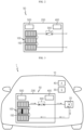
- FIG. 1 is a diagram for illustrating a vehicle according to an embodiment of the present disclosure
- FIG. 2 is a diagram for illustrating a battery pack of the vehicle of FIG. 1 .
- a vehicle 1 may be an electric vehicle or a hybrid electric vehicle, which includes a secondary battery as an energy source.
- the vehicle 1 will be described as an electric vehicle.
- the vehicle 1 may include a body 10, a motor unit 20, a gear 30, an alarm unit 40 and a battery pack 50.
- the body 10 forms an appearance of the vehicle 1 and has a driving space and a riding space for a user such as a driver, and various components of the vehicle 1 may be accommodated in or mounted to the body 10.
- the motor unit 20 is for operating the vehicle 1 and the like, and may be provided to the body 10.
- the motor unit 20 may be connected to a gear 30 and a battery pack 50, explained later, and may be provided as an electric motor.
- the gear 30 is connected to the motor unit 20 and may be shifted according to manipulation of the user such as a driver.
- the gear 30 may be shifted to a running mode, a neutral mode, a reverse mode or a parking mode according to the user manipulation while the vehicle is running or stopped.
- the alarm unit 40 is connected to warning unit 400 of the battery pack 50, explained later, and may be provided at a position that may be recognized by the user such as a driver when a danger situation occurs at the body 10.
- the alarm unit 40 may be provided in the form of a display unit that provides visual information to the user to inform occurrence of the danger situation, a sound unit that provides auditory information to the user, or an audiovisual unit that provides both visual information and auditory information.
- the alarm unit 40 may be provided in other forms as well, without being limited to the above, as long as the user may be informed of the occurrence of the danger situation.
- the battery pack 50 may be provided to the body 10 as an energy source of the vehicle 1.
- the battery pack 50 may provide energy for operating the motor unit 20.
- the battery pack 50 may include a battery module 100, a pack case 200, a relay unit 300, a warning unit 400, and a control unit 500.
- At least one battery module 100 or a plurality of battery modules 100 may be provided.
- a plurality of battery modules 100 are provided.
- the plurality of battery modules 100 are electrically connected to each other and may be provided inside the pack case 200, explained later.
- Each of the plurality of battery module 100 may include a battery cell 150.
- the battery cell 150 is a secondary battery, and may be provided as a pouch-type secondary battery, a rectangular secondary battery, or a cylindrical secondary battery. Hereinafter, in this embodiment, the battery cell 150 will be described as a pouch-type secondary battery.
- At least one battery cell 150 or a plurality of battery cells 150 may be provided.
- a plurality of battery cells 150 are provided and stacked on each other so as to be electrically connected to each other.
- the pack case 200 is mounted to the body 10, and may accommodate the plurality of battery modules 100, the relay unit 300, the warning unit 400 and the control unit 500, explained later.
- the relay unit 300 is provided to the pack case 200, and may be electrically connected to the control unit 500, explained later.
- the relay unit 300 may connect the at least one battery module 100, or the plurality of battery modules 100 in this embodiment, to the motor unit 20 of the vehicle 1.
- the warning unit 400 is for transmitting predetermined danger information to the user such as a driver of the vehicle 1, and is provided to the pack case 200.
- the warning unit 400 may be electrically connected to the control unit 500, explained later.
- the warning unit 400 may be connected to the alarm unit 40 of the vehicle 1, and when a danger situation occurs, the warning unit 400 may provide the danger information or the like to the alarm unit 40 to guide the operation of the alarm unit 40.
- the control unit 500 is provided to the pack case 200, and may be electrically connected to the motor unit 20, the gear 30 and the alarm unit 40 of the vehicle 1 to control operations of the motor unit 20, the gear 30 and the alarm unit 40.
- the control unit 500 may be electrically connected to the battery module 100, the relay unit 300 and the warning unit 400 to control operations of the battery module 100, the relay unit 300 and the warning unit 400.
- control unit 500 According to this embodiment, the detailed control operation of the control unit 500 according to this embodiment will be described in more detail.
- control unit 500 may operate the relay unit 300 so that the motor unit 20 idles.
- control unit 500 may close a switch of the relay unit 300 so that the motor unit 20 idles.
- control unit 500 may shift the gear 30 of the vehicle 1 to the neutral mode.
- control unit 500 may control the warning unit 400 to send a danger signal to the driver of the vehicle 1.
- control unit 500 may control the warning unit 400 to transmit the danger information of the warning unit 400 to the alarm unit 40 of the vehicle 1, and control the alarm unit 40 to send the danger signal to the driver.
- the alarm unit 40 may transmit the danger signal to the driver by emitting a light through a display or generating a horn through a speaker.
- control unit 500 may shift the gear 30 of the vehicle 1 to the neutral mode so that the motor unit 20 idles.
- control unit 500 may shift the gear 30 of the vehicle 1 to the neutral mode so that the motor unit 20 idles.
- FIG. 3 is a diagram for illustrating an operation of the battery pack of FIG. 2 when an abnormal situation occurs.
- an abnormal situation may occur at the battery cell 155 of the battery module 100.
- the temperature may rise according to overheating or overcurrent.
- the battery cell 155 may be exploded or ignited, which may lead to a thermal runaway to the battery cells of the surrounding battery modules 100, resulting in an explosion of the entire battery pack or the like. In this case, a great danger may be caused the user such as a driver and an occupant of the vehicle 1.
- control unit 500 may control the battery pack 50 or allow the motor unit 20 to idle in order to prevent the occurrence of thermal runaway.
- the control unit 500 may control the motor unit 20 to idle so that the energy level of the battery cells 155 of the battery module 100 is lowered to prevent thermal runaway.
- SOC state of charge
- the specific SOC or below may be approximately 30 percent or below.
- control unit 500 may firstly control the warning unit 400 to notify this information to the user such as a driver of the vehicle 1 such that the user may recognize this danger situation through the alarm unit 40 of the vehicle 1.
- control unit 500 may shift the state of the gear 30 of the vehicle 1 to a neutral mode. If the alarm is generated through the warning unit 400 and the gear 30 is completely shifted to the neutral mode, the control unit 500 may close the switch of the relay unit 300 to operate the relay unit 300 so that the motor unit 20 idles.
- the energy of the battery module 100 may be converted into kinetic energy through idling of the motor unit 20 and be quickly released.
- the idling of the motor unit 20 may be continued until the SOC is lowered to a predetermined SOC or below.
- the battery pack 50 may effectively prevent thermal runaway of the battery cell 155 through idling of the motor unit 20 of the vehicle 1 under the control of the control unit 500, thereby significantly reducing the risk of explosion or chain ignition of the battery module 100.
- the battery pack 50 may effectively prevent a large accident of such as explosion of the battery pack 50, even the vehicle 1, when an abnormal situation occurs at the specific battery cell 155.
- FIG. 4 is a flowchart for illustrating a control method when an abnormal situation occurs at the battery pack of FIG. 2 , while the vehicle of FIG. 1 is stopped.
- the control unit of the battery pack may determine whether a temperature of the battery cell of at least one battery module among the battery modules is higher than a preset temperature (S10).
- control unit may operate the warning unit (S 12) so that the user such as a driver recognizes the danger situation through the alarm unit.
- the control unit may determine whether the gear of the vehicle is in a neutral state (S14), and if the gear is not in the neutral state, the control unit may shift the gear to the neutral mode (S15).
- control unit may operate the relay unit by closing the switch of the relay unit (S16). Then, the control unit may convert the energy of the battery module into kinetic energy through idling of the motor unit and release the energy (S18), in order to lower the SOC of the entire battery module so that thermal runaway does not occur at the battery cell or the battery module.
- FIG. 5 is a flowchart for illustrating a control method when an abnormal situation occurs at the battery pack of FIG. 2 , while the vehicle of FIG. 1 is running.
- the control unit of the battery pack may determine whether a temperature of the battery cell of at least one of the battery modules is higher than a preset temperature (S20).
- control unit may operate the warning unit (S22) so that the user such as a driver recognizes the danger situation through the alarm unit.
- the control unit may determine whether the vehicle is stopped (S23). If the vehicle is in a stopped state, the control unit may determine whether the gear of the vehicle is in a neutral state (S24), and if the gear is not in the neutral state, the control unit may shift the gear to the neutral mode (S25). Meanwhile, if the vehicle is not in a stopped state but in a running state according to the determination (S23) of whether the vehicle is stopped, the control unit may shift the gear to the neutral mode.
- control unit may operate the relay unit by closing the switch of the relay unit (S26). Then, the control unit may convert the energy of the battery module into kinetic energy through idling of the motor unit and release the energy (S28), in order to lower the SOC of the entire battery module so that thermal runaway does not occur at the battery cell or the battery module.
- FIG. 6 is a diagram for illustrating a battery pack according to another embodiment of the vehicle of FIG. 1
- FIG. 7 is a diagram for illustrating an operation of the battery pack of FIG. 6 when an abnormal situation occurs.
- a battery pack 55 of the vehicle 1 is similar to the battery pack 50 of the former embodiment, components substantially identical or similar to the former embodiment will not be described in detail, and hereinafter, features different from the former embodiment will be described in detail.
- the battery pack 55 may include a battery module 100, a pack case 200, a relay unit 300, a warning unit 400, a control unit 500, and an external resistor unit 600.
- the battery module 100, the pack case 200, the relay unit 300, the warning unit 400 and the control unit 500 are substantially identical or similar to the former embodiment and thus will not be described in detail.
- the external resistor unit 600 is provided inside the pack case 200 or outside the pack case 200, and may connect the relay unit 300 to the motor unit 20 of the vehicle 1.
- the external resistor unit 600 may discharge the energy of the battery module 100 as thermal energy. That is, in this embodiment, when the temperature of a specific battery cell 155 of at least one of the battery modules 100 rises over a predetermined temperature due to overheating or the like, the energy of the battery module 100 may also be discharged through the external resistor unit 600 along with the energy release due to idling of the motor unit 20.
- the battery pack 55 may more effectively prevent the occurrence of a danger situation such as thermal runaway.
- the battery packs 50, 55 having an improved safety by preventing thermal runaway, the vehicle 1 including the battery pack 50, 55, and the control method of the battery pack 50, 55.
Landscapes
- Engineering & Computer Science (AREA)
- Power Engineering (AREA)
- Transportation (AREA)
- Mechanical Engineering (AREA)
- Life Sciences & Earth Sciences (AREA)
- Sustainable Development (AREA)
- Sustainable Energy (AREA)
- Chemical & Material Sciences (AREA)
- Chemical Kinetics & Catalysis (AREA)
- Electrochemistry (AREA)
- General Chemical & Material Sciences (AREA)
- Manufacturing & Machinery (AREA)
- Aviation & Aerospace Engineering (AREA)
- Microelectronics & Electronic Packaging (AREA)
- Electric Propulsion And Braking For Vehicles (AREA)
- Secondary Cells (AREA)
- Charge And Discharge Circuits For Batteries Or The Like (AREA)
- Protection Of Static Devices (AREA)
- Battery Mounting, Suspending (AREA)
Abstract
Description
- The present application claims priority to
Korean Patent Application No. 10-2019-0145242 filed on November 13, 2019 - The present disclosure relates to a battery pack, a vehicle including the battery pack, and a control method of the battery pack.
- Secondary batteries which are highly applicable to various products and exhibit superior electrical properties such as high energy density, etc. are commonly used not only in portable devices but also in electric vehicles (EVs) or hybrid electric vehicles (HEVs) driven by electrical power sources. The secondary battery is drawing attention as a new energy source for enhancing energy efficiency and environment friendliness in that the use of fossil fuels can be reduced greatly and no byproduct is generated during energy consumption.
- Secondary batteries widely used at present include lithium ion batteries, lithium polymer batteries, nickel cadmium batteries, nickel hydrogen batteries, nickel zinc batteries and the like. An operating voltage of the unit secondary battery cell, namely a unit battery cell, is about 2.5V to 4.5V. Therefore, if a higher output voltage is required, a plurality of battery cells may be connected in series to configure a battery pack. In addition, depending on the charge/discharge capacity required for the battery pack, a plurality of battery cells may be connected in parallel to configure a battery pack. Thus, the number of battery cells included in the battery pack may be variously set according to the required output voltage or the demanded charge/discharge capacity.
- Meanwhile, when a plurality of battery cells are connected in series or in parallel to configure a battery pack, it is common to configure a battery module composed of at least one battery cell first, and then configure a battery pack by using at least one battery module and adding other components.
- The conventional battery pack includes battery modules, each having a plurality of battery cells. Here, when an abnormal situation occurs due to expansion of a battery cell in any one battery module in an overheating situation over a predetermined temperature, if the abnormal situation is not quickly solved, thermal runaway may propagate to neighboring battery modules, which may lead to explosion or the like of the battery pack and thus cause a great danger to the user.
- Therefore, when an abnormal situation occurs at a specific battery cell of the battery module in an overheating situation over a predetermined temperature, it is necessary to promptly solve the abnormal situation. In particular, it is necessary to secure safety by preventing propagation of the thermal runaway before the thermal runaway leads to neighboring the surrounding battery modules to cause explosion or fire of the battery pack.
- The present disclosure is directed to providing a battery pack, which may improve the safety by preventing thermal runaway, a vehicle including the battery pack, and a control method of the battery pack.
- In one aspect of the present disclosure, there is provided a battery pack provided to a vehicle, comprising: at least one battery module having at least one battery cell; a relay unit configured to connect the at least one battery module to a motor unit of the vehicle; and a control unit connected to the relay unit and the motor unit to control the relay unit and the motor unit, wherein when a temperature of the at least one battery cell of the at least one battery module rises over a predetermined temperature, the control unit operates the relay unit so that the motor unit idles.
- When the temperature of the at least one battery cell of the at least one battery module rises over the predetermined temperature, the control unit may close a switch of the relay unit.
- When the temperature of the at least one battery cell of the at least one battery module rises over the predetermined temperature, the control unit may shift a gear of the vehicle to a neutral mode.
- The battery pack may further comprise a warning unit configured to transmit predetermined danger information to a driver of the vehicle.
- When the temperature of the at least one battery cell of the at least one battery module rises over the predetermined temperature, the control unit may control the warning unit to send a danger signal to the driver of the vehicle.
- The control unit may shift a gear of the vehicle to a neutral mode together with operating the warning unit so that the motor unit idles.
- After a preset predetermined time passes from the operation of the warning unit, the control unit may shift a gear of the vehicle to a neutral mode so that the motor unit idles.
- The battery pack may further comprise at least one external resistor unit configured to connect the relay unit and the motor unit.
- In addition, the present disclosure provides a control method of a battery pack provided to a vehicle, comprising: shifting a gear of the vehicle to a neutral mode, when a temperature of at least one battery cell of at least one battery module rises over a predetermined temperature; operating a relay unit connected to the at least one battery module over the predetermined temperature; and allowing a motor unit of the vehicle connected to the relay unit to idle according to an operation of the relay unit.
- Moreover, the present disclosure provides a vehicle comprising: at least one battery pack according to the above embodiments.
- According to various embodiments as above, it is possible to provide a battery pack, which may improve the safety by preventing thermal runaway, a vehicle including the battery pack, and a control method of the battery pack.
- The accompanying drawings illustrate a preferred embodiment of the present disclosure and together with the foregoing disclosure, serve to provide further understanding of the technical features of the present disclosure, and thus, the present disclosure is not construed as being limited to the drawing.
-
FIG. 1 is a diagram for illustrating a vehicle according to an embodiment of the present disclosure. -
FIG. 2 is a diagram for illustrating a battery pack of the vehicle ofFIG. 1 . -
FIG. 3 is a diagram for illustrating an operation of the battery pack ofFIG. 2 when an abnormal situation occurs. -
FIG. 4 is a flowchart for illustrating a control method when an abnormal situation occurs at the battery pack ofFIG. 2 , while the vehicle ofFIG. 1 is stopped. -
FIG. 5 is a flowchart for illustrating a control method when an abnormal situation occurs at the battery pack ofFIG. 2 , while the vehicle ofFIG. 1 is running. -
FIG. 6 is a diagram for illustrating a battery pack according to another embodiment of the vehicle ofFIG. 1 . -
FIG. 7 is a diagram for illustrating an operation of the battery pack ofFIG. 6 when an abnormal situation occurs. - The present disclosure will become more apparent by describing in detail the embodiments of the present disclosure with reference to the accompanying drawings. It should be understood that the embodiments disclosed herein are illustrative only for better understanding of the present disclosure, and that the present disclosure may be modified in various ways. In addition, for ease understanding of the present disclosure, the accompanying drawings are not drawn to real scale, but the dimensions of some components may be exaggerated.
-
FIG. 1 is a diagram for illustrating a vehicle according to an embodiment of the present disclosure, andFIG. 2 is a diagram for illustrating a battery pack of the vehicle ofFIG. 1 . - Referring to
FIGS. 1 and2 , a vehicle 1 may be an electric vehicle or a hybrid electric vehicle, which includes a secondary battery as an energy source. Hereinafter, in this embodiment, the vehicle 1 will be described as an electric vehicle. - The vehicle 1 may include a
body 10, amotor unit 20, agear 30, analarm unit 40 and abattery pack 50. - The
body 10 forms an appearance of the vehicle 1 and has a driving space and a riding space for a user such as a driver, and various components of the vehicle 1 may be accommodated in or mounted to thebody 10. - The
motor unit 20 is for operating the vehicle 1 and the like, and may be provided to thebody 10. Themotor unit 20 may be connected to agear 30 and abattery pack 50, explained later, and may be provided as an electric motor. - The
gear 30 is connected to themotor unit 20 and may be shifted according to manipulation of the user such as a driver. For example, thegear 30 may be shifted to a running mode, a neutral mode, a reverse mode or a parking mode according to the user manipulation while the vehicle is running or stopped. - The
alarm unit 40 is connected towarning unit 400 of thebattery pack 50, explained later, and may be provided at a position that may be recognized by the user such as a driver when a danger situation occurs at thebody 10. - The
alarm unit 40 may be provided in the form of a display unit that provides visual information to the user to inform occurrence of the danger situation, a sound unit that provides auditory information to the user, or an audiovisual unit that provides both visual information and auditory information. Thealarm unit 40 may be provided in other forms as well, without being limited to the above, as long as the user may be informed of the occurrence of the danger situation. - The
battery pack 50 may be provided to thebody 10 as an energy source of the vehicle 1. Thebattery pack 50 may provide energy for operating themotor unit 20. - The
battery pack 50 may include abattery module 100, apack case 200, arelay unit 300, awarning unit 400, and acontrol unit 500. - At least one
battery module 100 or a plurality ofbattery modules 100 may be provided. Hereinafter, in this embodiment, it will be described that a plurality ofbattery modules 100 are provided. The plurality ofbattery modules 100 are electrically connected to each other and may be provided inside thepack case 200, explained later. - Each of the plurality of
battery module 100 may include abattery cell 150. - The
battery cell 150 is a secondary battery, and may be provided as a pouch-type secondary battery, a rectangular secondary battery, or a cylindrical secondary battery. Hereinafter, in this embodiment, thebattery cell 150 will be described as a pouch-type secondary battery. - At least one
battery cell 150 or a plurality ofbattery cells 150 may be provided. Hereinafter, in this embodiment, it will be described that a plurality ofbattery cells 150 are provided and stacked on each other so as to be electrically connected to each other. - The
pack case 200 is mounted to thebody 10, and may accommodate the plurality ofbattery modules 100, therelay unit 300, thewarning unit 400 and thecontrol unit 500, explained later. - The
relay unit 300 is provided to thepack case 200, and may be electrically connected to thecontrol unit 500, explained later. Therelay unit 300 may connect the at least onebattery module 100, or the plurality ofbattery modules 100 in this embodiment, to themotor unit 20 of the vehicle 1. - The
warning unit 400 is for transmitting predetermined danger information to the user such as a driver of the vehicle 1, and is provided to thepack case 200. Thewarning unit 400 may be electrically connected to thecontrol unit 500, explained later. - The
warning unit 400 may be connected to thealarm unit 40 of the vehicle 1, and when a danger situation occurs, thewarning unit 400 may provide the danger information or the like to thealarm unit 40 to guide the operation of thealarm unit 40. - The
control unit 500 is provided to thepack case 200, and may be electrically connected to themotor unit 20, thegear 30 and thealarm unit 40 of the vehicle 1 to control operations of themotor unit 20, thegear 30 and thealarm unit 40. - The
control unit 500 may be electrically connected to thebattery module 100, therelay unit 300 and thewarning unit 400 to control operations of thebattery module 100, therelay unit 300 and thewarning unit 400. - Hereinafter, the detailed control operation of the
control unit 500 according to this embodiment will be described in more detail. - If a temperature of the at least one
battery cell 150 of the at least onebattery module 100 rises over a predetermined temperature, thecontrol unit 500 may operate therelay unit 300 so that themotor unit 20 idles. - Specifically, if the temperature of the at least one
battery cell 150 of the at least onebattery module 100 rises over the predetermined temperature, thecontrol unit 500 may close a switch of therelay unit 300 so that themotor unit 20 idles. - If the temperature of the at least one
battery cell 150 of the at least onebattery module 100 rises over the predetermined temperature, thecontrol unit 500 may shift thegear 30 of the vehicle 1 to the neutral mode. - If the temperature of the at least one
battery cell 150 of the at least onebattery module 100 rises over the predetermined temperature, thecontrol unit 500 may control thewarning unit 400 to send a danger signal to the driver of the vehicle 1. - Specifically, the
control unit 500 may control thewarning unit 400 to transmit the danger information of thewarning unit 400 to thealarm unit 40 of the vehicle 1, and control thealarm unit 40 to send the danger signal to the driver. Here, thealarm unit 40 may transmit the danger signal to the driver by emitting a light through a display or generating a horn through a speaker. - Together with operating the
warning unit 400, thecontrol unit 500 may shift thegear 30 of the vehicle 1 to the neutral mode so that themotor unit 20 idles. In addition, after a preset predetermined time passes from the operation of thewarning unit 400, thecontrol unit 500 may shift thegear 30 of the vehicle 1 to the neutral mode so that themotor unit 20 idles. - Hereinafter, the detailed operation of the
battery pack 50 according to this embodiment when an abnormal situation occurs will be described in more detail. -
FIG. 3 is a diagram for illustrating an operation of the battery pack ofFIG. 2 when an abnormal situation occurs. - Referring to
FIG. 3 , in thebattery pack 50 of the vehicle 1, an abnormal situation may occur at thebattery cell 155 of thebattery module 100. Specifically, in thebattery cell 155 of at least one of thebattery modules 100, the temperature may rise according to overheating or overcurrent. - If the temperature of the
battery cell 155 keeps rising over a predetermined temperature, thebattery cell 155 may be exploded or ignited, which may lead to a thermal runaway to the battery cells of the surroundingbattery modules 100, resulting in an explosion of the entire battery pack or the like. In this case, a great danger may be caused the user such as a driver and an occupant of the vehicle 1. - In the
battery pack 50 of this embodiment, in order to prevent this problem, when the temperature of the at least onebattery cell 155 rises over the predetermined temperature, thecontrol unit 500 may control thebattery pack 50 or allow themotor unit 20 to idle in order to prevent the occurrence of thermal runaway. - Specifically, in the
battery pack 50 according to this embodiment, when the temperature of the at least onebattery cell 155 rises over the predetermined temperature, thecontrol unit 500 may control themotor unit 20 to idle so that the energy level of thebattery cells 155 of thebattery module 100 is lowered to prevent thermal runaway. In the case of a state of charge (SOC) of thebattery module 100 is at a specific SOC or below, thermal runaway does not occur, and even though thermal runaway occurs, only a small amount of heat is released. In this embodiment, the specific SOC or below may be approximately 30 percent or below. - Hereinafter, a mechanism for preventing thermal runaway according to this embodiment will be described in more detail.
- If the temperature of the at least one
battery cell 155 of thebattery module 100 rises above the preset predetermined temperature, thecontrol unit 500 may firstly control thewarning unit 400 to notify this information to the user such as a driver of the vehicle 1 such that the user may recognize this danger situation through thealarm unit 40 of the vehicle 1. - After that, the
control unit 500 may shift the state of thegear 30 of the vehicle 1 to a neutral mode. If the alarm is generated through thewarning unit 400 and thegear 30 is completely shifted to the neutral mode, thecontrol unit 500 may close the switch of therelay unit 300 to operate therelay unit 300 so that themotor unit 20 idles. - Accordingly, the energy of the
battery module 100 may be converted into kinetic energy through idling of themotor unit 20 and be quickly released. Here, the idling of themotor unit 20 may be continued until the SOC is lowered to a predetermined SOC or below. - When an abnormal situation occurs due to overheating of a
specific battery cell 155, thebattery pack 50 according to this embodiment may effectively prevent thermal runaway of thebattery cell 155 through idling of themotor unit 20 of the vehicle 1 under the control of thecontrol unit 500, thereby significantly reducing the risk of explosion or chain ignition of thebattery module 100. - Therefore, the
battery pack 50 according to this embodiment may effectively prevent a large accident of such as explosion of thebattery pack 50, even the vehicle 1, when an abnormal situation occurs at thespecific battery cell 155. -
FIG. 4 is a flowchart for illustrating a control method when an abnormal situation occurs at the battery pack ofFIG. 2 , while the vehicle ofFIG. 1 is stopped. - Referring to
FIG. 4 , when the vehicle is stopped, the control unit of the battery pack may determine whether a temperature of the battery cell of at least one battery module among the battery modules is higher than a preset temperature (S10). - If the temperature of the at least one battery cell is higher than the preset temperature, the control unit may operate the warning unit (S 12) so that the user such as a driver recognizes the danger situation through the alarm unit.
- The control unit may determine whether the gear of the vehicle is in a neutral state (S14), and if the gear is not in the neutral state, the control unit may shift the gear to the neutral mode (S15).
- After that, the control unit may operate the relay unit by closing the switch of the relay unit (S16). Then, the control unit may convert the energy of the battery module into kinetic energy through idling of the motor unit and release the energy (S18), in order to lower the SOC of the entire battery module so that thermal runaway does not occur at the battery cell or the battery module.
-
FIG. 5 is a flowchart for illustrating a control method when an abnormal situation occurs at the battery pack ofFIG. 2 , while the vehicle ofFIG. 1 is running. - Referring to
FIG. 5 , when the vehicle is running, the control unit of the battery pack may determine whether a temperature of the battery cell of at least one of the battery modules is higher than a preset temperature (S20). - If the temperature of the at least one battery cell is higher than the preset temperature, the control unit may operate the warning unit (S22) so that the user such as a driver recognizes the danger situation through the alarm unit.
- The control unit may determine whether the vehicle is stopped (S23). If the vehicle is in a stopped state, the control unit may determine whether the gear of the vehicle is in a neutral state (S24), and if the gear is not in the neutral state, the control unit may shift the gear to the neutral mode (S25). Meanwhile, if the vehicle is not in a stopped state but in a running state according to the determination (S23) of whether the vehicle is stopped, the control unit may shift the gear to the neutral mode.
- After that, the control unit may operate the relay unit by closing the switch of the relay unit (S26). Then, the control unit may convert the energy of the battery module into kinetic energy through idling of the motor unit and release the energy (S28), in order to lower the SOC of the entire battery module so that thermal runaway does not occur at the battery cell or the battery module.
-
FIG. 6 is a diagram for illustrating a battery pack according to another embodiment of the vehicle ofFIG. 1 , andFIG. 7 is a diagram for illustrating an operation of the battery pack ofFIG. 6 when an abnormal situation occurs. - Since a
battery pack 55 of the vehicle 1 according to this embodiment is similar to thebattery pack 50 of the former embodiment, components substantially identical or similar to the former embodiment will not be described in detail, and hereinafter, features different from the former embodiment will be described in detail. - Referring to
FIGS. 6 and7 , thebattery pack 55 may include abattery module 100, apack case 200, arelay unit 300, awarning unit 400, acontrol unit 500, and anexternal resistor unit 600. - The
battery module 100, thepack case 200, therelay unit 300, thewarning unit 400 and thecontrol unit 500 are substantially identical or similar to the former embodiment and thus will not be described in detail. - The
external resistor unit 600 is provided inside thepack case 200 or outside thepack case 200, and may connect therelay unit 300 to themotor unit 20 of the vehicle 1. - If the
relay unit 300 is closed, theexternal resistor unit 600 may discharge the energy of thebattery module 100 as thermal energy. That is, in this embodiment, when the temperature of aspecific battery cell 155 of at least one of thebattery modules 100 rises over a predetermined temperature due to overheating or the like, the energy of thebattery module 100 may also be discharged through theexternal resistor unit 600 along with the energy release due to idling of themotor unit 20. - Therefore, when an abnormal situation occurs at a
specific battery cell 155 of thebattery module 100 due to abnormal overheating or the like, thebattery pack 55 according to this embodiment may more effectively prevent the occurrence of a danger situation such as thermal runaway. - According to various embodiments as described above, it is possible to provide the battery packs 50, 55 having an improved safety by preventing thermal runaway, the vehicle 1 including the
battery pack battery pack - While the embodiments of the present disclosure have been shown and described, it should be understood that the present disclosure is not limited to the specific embodiments described.
-
- 1: vehicle
- 10: body
- 20: motor unit
- 30: gear
- 40: alarm unit
- 50, 55: battery pack
- 100: battery module
- 150, 155: battery cell
- 200: pack case
- 300: relay unit
- 400: warning unit
- 500: control unit
- 600: external resistor unit
Claims (10)
- A battery pack (50) provided in a vehicle (1), comprising:at least one battery module (100) having at least one battery cell (150);a relay unit (300) configured to connect the at least one battery module (100) to a motor unit (20) of the vehicle (1); anda control unit (500) connected to the relay unit (300) and the motor unit (20) to control the relay unit (300) and the motor unit (20),wherein when a temperature of the at least one battery cell of the at least one battery module rises over a predetermined temperature, the control unit (500) operates the relay unit (300), so that the motor unit (20) idles.
- The battery pack (50) according to claim 1,
wherein when the temperature of the at least one battery cell (150) of the at least one battery module (100) rises over the predetermined temperature, the control unit (500) closes a switch of the relay unit (300). - The battery pack (50) according to claim 2,
wherein when the temperature of the at least one battery cell (150) of the at least one battery module (100) rises over the predetermined temperature, the control unit (500) shifts a gear of the vehicle to a neutral mode. - The battery pack (50) according to claim 2, further comprising:a warning unit (400) configured to transmit predetermined danger information to a driver of the vehicle (1).
- The battery pack (50) according to claim 3,
wherein when the temperature of the at least one battery cell of the at least one battery module rises over the predetermined temperature, the control unit (500) controls the warning unit (400) to send a danger signal to the driver of the vehicle (1). - The battery pack (50) according to claim 5,
wherein the control unit (300) shifts a gear (30) of the vehicle (1) to a neutral mode together with operating the warning unit (400) so that the motor unit (20) idles. - The battery pack (50) according to claim 5,
wherein after a preset predetermined time passes from the operation of the warning unit, the control unit (500) shifts a gear (30) of the vehicle (1) to a neutral mode so that the motor unit (20) idles. - The battery pack (50) according to claim 1, further comprising:
at least one external resistor unit (600) configured to connect the relay unit (300) and the motor unit (20). - A control method of a battery pack (50) provided to a vehicle, comprising:shifting (S15) a gear (30) of the vehicle (1) to a neutral mode, when a temperature of at least one battery cell (150) of at least one battery module (100) rises over a predetermined temperature;operating (S16) a relay unit (300) connected to the at least one battery module (100) over the predetermined temperature; andallowing (S18) a motor unit (20) of the vehicle connected to the relay unit (300) to idle according to an operation of the relay unit (300).
- A vehicle (1), comprising at least one battery pack (50) according to claim 1.
Applications Claiming Priority (3)
| Application Number | Priority Date | Filing Date | Title |
|---|---|---|---|
| KR1020190145242A KR102902469B1 (en) | 2019-11-13 | 2019-11-13 | Battery pack, vehicle comprising the battery pack and control method of the battery pack |
| PCT/KR2020/014112 WO2021096079A1 (en) | 2019-11-13 | 2020-10-15 | Battery pack, vehicle including battery pack, and method for controlling battery pack |
| EP20886347.2A EP3954574B1 (en) | 2019-11-13 | 2020-10-15 | Battery pack, vehicle including battery pack, and method for controlling battery pack |
Related Parent Applications (2)
| Application Number | Title | Priority Date | Filing Date |
|---|---|---|---|
| EP20886347.2A Division EP3954574B1 (en) | 2019-11-13 | 2020-10-15 | Battery pack, vehicle including battery pack, and method for controlling battery pack |
| EP20886347.2A Division-Into EP3954574B1 (en) | 2019-11-13 | 2020-10-15 | Battery pack, vehicle including battery pack, and method for controlling battery pack |
Publications (3)
| Publication Number | Publication Date |
|---|---|
| EP4354620A2 true EP4354620A2 (en) | 2024-04-17 |
| EP4354620A3 EP4354620A3 (en) | 2024-07-10 |
| EP4354620B1 EP4354620B1 (en) | 2025-05-07 |
Family
ID=75913033
Family Applications (2)
| Application Number | Title | Priority Date | Filing Date |
|---|---|---|---|
| EP20886347.2A Active EP3954574B1 (en) | 2019-11-13 | 2020-10-15 | Battery pack, vehicle including battery pack, and method for controlling battery pack |
| EP24160488.3A Active EP4354620B1 (en) | 2019-11-13 | 2020-10-15 | Battery pack, vehicle including battery pack, and method for controlling battery pack |
Family Applications Before (1)
| Application Number | Title | Priority Date | Filing Date |
|---|---|---|---|
| EP20886347.2A Active EP3954574B1 (en) | 2019-11-13 | 2020-10-15 | Battery pack, vehicle including battery pack, and method for controlling battery pack |
Country Status (9)
| Country | Link |
|---|---|
| US (1) | US12194864B2 (en) |
| EP (2) | EP3954574B1 (en) |
| JP (1) | JP7278388B2 (en) |
| KR (1) | KR102902469B1 (en) |
| CN (2) | CN112874383B (en) |
| ES (2) | ES3031969T3 (en) |
| HU (2) | HUE066637T2 (en) |
| PL (2) | PL4354620T3 (en) |
| WO (1) | WO2021096079A1 (en) |
Families Citing this family (1)
| Publication number | Priority date | Publication date | Assignee | Title |
|---|---|---|---|---|
| KR102902469B1 (en) | 2019-11-13 | 2025-12-18 | 주식회사 엘지에너지솔루션 | Battery pack, vehicle comprising the battery pack and control method of the battery pack |
Family Cites Families (24)
| Publication number | Priority date | Publication date | Assignee | Title |
|---|---|---|---|---|
| KR0130485Y1 (en) | 1993-11-16 | 1999-10-01 | 전성원 | Battery Stabilizer for Vehicles |
| JPH10271603A (en) | 1997-03-28 | 1998-10-09 | Mitsubishi Motors Corp | Electric car |
| JP3406542B2 (en) | 1999-09-28 | 2003-05-12 | ダイハツ工業株式会社 | Travel control device for hybrid vehicle and control method therefor |
| JP5019870B2 (en) | 2006-12-27 | 2012-09-05 | ボッシュ株式会社 | Control method of hybrid vehicle |
| JP5517398B2 (en) | 2007-03-15 | 2014-06-11 | 三菱重工業株式会社 | Power storage system |
| KR101068583B1 (en) | 2009-01-09 | 2011-09-30 | 부산대학교 산학협력단 | Safety system and control method of hybrid vehicle |
| KR101086974B1 (en) | 2009-03-03 | 2011-11-29 | 주식회사 엘지화학 | Apparatus and method for controlling relay in electric drive vehicle |
| JP2011062058A (en) | 2009-09-14 | 2011-03-24 | Yukinobu Mori | Electric vehicle system |
| JP2011182526A (en) * | 2010-02-26 | 2011-09-15 | Sanyo Electric Co Ltd | Charge and discharge control system for battery and electric vehicle mounting the same, and charge and discharge control method for battery |
| JP2011190690A (en) | 2010-03-11 | 2011-09-29 | Hitachi Vehicle Energy Ltd | Battery control device and on-vehicle power source device |
| KR20120114608A (en) | 2011-04-07 | 2012-10-17 | (주)브이이엔에스 | Electric vehicle control method |
| KR20140042597A (en) * | 2012-09-28 | 2014-04-07 | 엘에스산전 주식회사 | Apparatus and method for discharging voltage of vehicle |
| WO2014068919A1 (en) * | 2012-10-29 | 2014-05-08 | 三洋電機株式会社 | Power supply device for vehicle performing regenerative braking |
| JP2015042094A (en) * | 2013-08-23 | 2015-03-02 | 日立オートモティブシステムズ株式会社 | Fuel cell vehicle controller |
| US10158102B2 (en) | 2013-08-30 | 2018-12-18 | Gogoro Inc. | Portable electrical energy storage device with thermal runaway mitigation |
| DE102015002080A1 (en) | 2015-02-18 | 2016-08-18 | Audi Ag | Battery cell for a battery of a motor vehicle, battery and motor vehicle |
| TWI613854B (en) | 2015-02-27 | 2018-02-01 | 睿能創意公司 | Portable electrical energy storage device with in-situ formable fluid channels |
| US9825345B2 (en) | 2015-02-27 | 2017-11-21 | Gogoro Inc. | Portable electrical energy storage device with in-situ formable fluid channels |
| JP6292154B2 (en) * | 2015-03-19 | 2018-03-14 | トヨタ自動車株式会社 | Power system |
| KR20160122351A (en) * | 2015-04-13 | 2016-10-24 | 엘에스산전 주식회사 | Force discharging device of inverter for electric vehicle |
| DE102016224002A1 (en) | 2016-12-02 | 2018-06-07 | Audi Ag | Discharging from a battery module having at least two battery cells of a battery having at least two battery modules |
| JP6708148B2 (en) * | 2017-03-07 | 2020-06-10 | 株式会社オートネットワーク技術研究所 | Automotive battery protection circuit |
| CN108515846B (en) * | 2018-04-08 | 2023-09-29 | 深圳市海德森科技股份有限公司 | Electric vehicle battery management system and electric vehicle battery management method |
| KR102902469B1 (en) | 2019-11-13 | 2025-12-18 | 주식회사 엘지에너지솔루션 | Battery pack, vehicle comprising the battery pack and control method of the battery pack |
-
2019
- 2019-11-13 KR KR1020190145242A patent/KR102902469B1/en active Active
-
2020
- 2020-10-15 PL PL24160488.3T patent/PL4354620T3/en unknown
- 2020-10-15 WO PCT/KR2020/014112 patent/WO2021096079A1/en not_active Ceased
- 2020-10-15 EP EP20886347.2A patent/EP3954574B1/en active Active
- 2020-10-15 JP JP2021539515A patent/JP7278388B2/en active Active
- 2020-10-15 US US17/425,818 patent/US12194864B2/en active Active
- 2020-10-15 HU HUE20886347A patent/HUE066637T2/en unknown
- 2020-10-15 HU HUE24160488A patent/HUE071897T2/en unknown
- 2020-10-15 ES ES24160488T patent/ES3031969T3/en active Active
- 2020-10-15 PL PL20886347.2T patent/PL3954574T3/en unknown
- 2020-10-15 EP EP24160488.3A patent/EP4354620B1/en active Active
- 2020-10-15 ES ES20886347T patent/ES2985192T3/en active Active
- 2020-10-30 CN CN202011191615.9A patent/CN112874383B/en active Active
- 2020-10-30 CN CN202022461853.9U patent/CN213734668U/en active Active
Also Published As
| Publication number | Publication date |
|---|---|
| US12194864B2 (en) | 2025-01-14 |
| PL3954574T3 (en) | 2024-07-22 |
| EP3954574A1 (en) | 2022-02-16 |
| WO2021096079A1 (en) | 2021-05-20 |
| HUE066637T2 (en) | 2024-08-28 |
| PL4354620T3 (en) | 2025-08-18 |
| EP4354620A3 (en) | 2024-07-10 |
| EP4354620B1 (en) | 2025-05-07 |
| CN112874383B (en) | 2025-09-12 |
| US20220161659A1 (en) | 2022-05-26 |
| ES3031969T3 (en) | 2025-07-14 |
| EP3954574A4 (en) | 2022-07-27 |
| JP7278388B2 (en) | 2023-05-19 |
| JP2022516650A (en) | 2022-03-01 |
| ES2985192T3 (en) | 2024-11-04 |
| KR102902469B1 (en) | 2025-12-18 |
| HUE071897T2 (en) | 2025-09-28 |
| EP3954574B1 (en) | 2024-04-17 |
| KR20210058144A (en) | 2021-05-24 |
| CN112874383A (en) | 2021-06-01 |
| CN213734668U (en) | 2021-07-20 |
Similar Documents
| Publication | Publication Date | Title |
|---|---|---|
| EP3588731B1 (en) | Battery management apparatus, and battery pack and automobile including same | |
| JP5804540B2 (en) | Battery pack with improved safety | |
| US11046206B2 (en) | Battery module with short-circuit unit, and battery pack and vehicle including the same | |
| JP2017004968A (en) | Battery pack with improved safety | |
| KR101327123B1 (en) | Lithium ion battery with tap holder | |
| JP7034405B2 (en) | Battery module, battery pack including it and automobile | |
| JP7027638B2 (en) | Battery module, battery pack including it and automobile | |
| KR102792385B1 (en) | Battery pack and vehicle comprising the battery pack | |
| KR20090131573A (en) | Power cut-off device when overcharging battery | |
| KR20230120673A (en) | Circuit control method, battery and its controller and management system, electrical device | |
| US11881597B2 (en) | Battery module with improved safety, battery pack comprising battery module, and vehicle comprising battery pack | |
| EP3985783A1 (en) | Battery module, battery rack comprising such battery module, and power storage device | |
| EP3954574B1 (en) | Battery pack, vehicle including battery pack, and method for controlling battery pack | |
| CN109155389B (en) | battery unit | |
| JP7405980B2 (en) | Battery packs and power storage devices | |
| KR20220056028A (en) | Energy drain system of battery pack and vehicle comprising the same | |
| US20220093976A1 (en) | Apparatus for resisting flame of battery of electric vehicle |
Legal Events
| Date | Code | Title | Description |
|---|---|---|---|
| PUAI | Public reference made under article 153(3) epc to a published international application that has entered the european phase |
Free format text: ORIGINAL CODE: 0009012 |
|
| STAA | Information on the status of an ep patent application or granted ep patent |
Free format text: STATUS: REQUEST FOR EXAMINATION WAS MADE |
|
| 17P | Request for examination filed |
Effective date: 20240229 |
|
| AC | Divisional application: reference to earlier application |
Ref document number: 3954574 Country of ref document: EP Kind code of ref document: P |
|
| AK | Designated contracting states |
Kind code of ref document: A2 Designated state(s): AL AT BE BG CH CY CZ DE DK EE ES FI FR GB GR HR HU IE IS IT LI LT LU LV MC MK MT NL NO PL PT RO RS SE SI SK SM TR |
|
| REG | Reference to a national code |
Ref country code: DE Ref legal event code: R079 Free format text: PREVIOUS MAIN CLASS: H01M0050249000 Ipc: B60L0058180000 Ref country code: DE Ref legal event code: R079 Ref document number: 602020051143 Country of ref document: DE Free format text: PREVIOUS MAIN CLASS: H01M0050249000 Ipc: B60L0058180000 |
|
| PUAL | Search report despatched |
Free format text: ORIGINAL CODE: 0009013 |
|
| AK | Designated contracting states |
Kind code of ref document: A3 Designated state(s): AL AT BE BG CH CY CZ DE DK EE ES FI FR GB GR HR HU IE IS IT LI LT LU LV MC MK MT NL NO PL PT RO RS SE SI SK SM TR |
|
| RIC1 | Information provided on ipc code assigned before grant |
Ipc: H01M 50/249 20210101ALI20240531BHEP Ipc: B60L 58/24 20190101ALI20240531BHEP Ipc: B60L 50/64 20190101ALI20240531BHEP Ipc: H01M 50/581 20210101ALI20240531BHEP Ipc: H01M 50/20 20210101ALI20240531BHEP Ipc: H01M 10/637 20140101ALI20240531BHEP Ipc: H01M 10/48 20060101ALI20240531BHEP Ipc: H01M 10/625 20140101ALI20240531BHEP Ipc: H01M 10/42 20060101ALI20240531BHEP Ipc: B60L 58/25 20190101ALI20240531BHEP Ipc: B60L 3/04 20060101ALI20240531BHEP Ipc: B60L 3/00 20190101ALI20240531BHEP Ipc: B60L 15/20 20060101ALI20240531BHEP Ipc: B60L 58/18 20190101AFI20240531BHEP |
|
| GRAP | Despatch of communication of intention to grant a patent |
Free format text: ORIGINAL CODE: EPIDOSNIGR1 |
|
| STAA | Information on the status of an ep patent application or granted ep patent |
Free format text: STATUS: GRANT OF PATENT IS INTENDED |
|
| INTG | Intention to grant announced |
Effective date: 20250219 |
|
| GRAS | Grant fee paid |
Free format text: ORIGINAL CODE: EPIDOSNIGR3 |
|
| GRAA | (expected) grant |
Free format text: ORIGINAL CODE: 0009210 |
|
| STAA | Information on the status of an ep patent application or granted ep patent |
Free format text: STATUS: THE PATENT HAS BEEN GRANTED |
|
| P01 | Opt-out of the competence of the unified patent court (upc) registered |
Free format text: CASE NUMBER: APP_14003/2025 Effective date: 20250321 |
|
| AC | Divisional application: reference to earlier application |
Ref document number: 3954574 Country of ref document: EP Kind code of ref document: P |
|
| AK | Designated contracting states |
Kind code of ref document: B1 Designated state(s): AL AT BE BG CH CY CZ DE DK EE ES FI FR GB GR HR HU IE IS IT LI LT LU LV MC MK MT NL NO PL PT RO RS SE SI SK SM TR |
|
| REG | Reference to a national code |
Ref country code: GB Ref legal event code: FG4D |
|
| REG | Reference to a national code |
Ref country code: CH Ref legal event code: EP |
|
| REG | Reference to a national code |
Ref country code: DE Ref legal event code: R096 Ref document number: 602020051143 Country of ref document: DE |
|
| REG | Reference to a national code |
Ref country code: IE Ref legal event code: FG4D |
|
| REG | Reference to a national code |
Ref country code: ES Ref legal event code: FG2A Ref document number: 3031969 Country of ref document: ES Kind code of ref document: T3 Effective date: 20250714 |
|
| REG | Reference to a national code |
Ref country code: SE Ref legal event code: TRGR |
|
| REG | Reference to a national code |
Ref country code: NL Ref legal event code: FP |
|
| REG | Reference to a national code |
Ref country code: HU Ref legal event code: AG4A Ref document number: E071897 Country of ref document: HU |
|
| PG25 | Lapsed in a contracting state [announced via postgrant information from national office to epo] |
Ref country code: PT Free format text: LAPSE BECAUSE OF FAILURE TO SUBMIT A TRANSLATION OF THE DESCRIPTION OR TO PAY THE FEE WITHIN THE PRESCRIBED TIME-LIMIT Effective date: 20250908 Ref country code: FI Free format text: LAPSE BECAUSE OF FAILURE TO SUBMIT A TRANSLATION OF THE DESCRIPTION OR TO PAY THE FEE WITHIN THE PRESCRIBED TIME-LIMIT Effective date: 20250507 |
|
| REG | Reference to a national code |
Ref country code: LT Ref legal event code: MG9D |
|
| PG25 | Lapsed in a contracting state [announced via postgrant information from national office to epo] |
Ref country code: NO Free format text: LAPSE BECAUSE OF FAILURE TO SUBMIT A TRANSLATION OF THE DESCRIPTION OR TO PAY THE FEE WITHIN THE PRESCRIBED TIME-LIMIT Effective date: 20250807 Ref country code: GR Free format text: LAPSE BECAUSE OF FAILURE TO SUBMIT A TRANSLATION OF THE DESCRIPTION OR TO PAY THE FEE WITHIN THE PRESCRIBED TIME-LIMIT Effective date: 20250808 |
|
| PGFP | Annual fee paid to national office [announced via postgrant information from national office to epo] |
Ref country code: IT Payment date: 20250924 Year of fee payment: 6 Ref country code: TR Payment date: 20250924 Year of fee payment: 6 Ref country code: NL Payment date: 20250922 Year of fee payment: 6 |
|
| REG | Reference to a national code |
Ref country code: AT Ref legal event code: MK05 Ref document number: 1792126 Country of ref document: AT Kind code of ref document: T Effective date: 20250507 |
|
| PG25 | Lapsed in a contracting state [announced via postgrant information from national office to epo] |
Ref country code: BG Free format text: LAPSE BECAUSE OF FAILURE TO SUBMIT A TRANSLATION OF THE DESCRIPTION OR TO PAY THE FEE WITHIN THE PRESCRIBED TIME-LIMIT Effective date: 20250507 |
|
| PGFP | Annual fee paid to national office [announced via postgrant information from national office to epo] |
Ref country code: BE Payment date: 20250922 Year of fee payment: 6 Ref country code: GB Payment date: 20250922 Year of fee payment: 6 |
|
| PG25 | Lapsed in a contracting state [announced via postgrant information from national office to epo] |
Ref country code: HR Free format text: LAPSE BECAUSE OF FAILURE TO SUBMIT A TRANSLATION OF THE DESCRIPTION OR TO PAY THE FEE WITHIN THE PRESCRIBED TIME-LIMIT Effective date: 20250507 |
|
| PG25 | Lapsed in a contracting state [announced via postgrant information from national office to epo] |
Ref country code: AT Free format text: LAPSE BECAUSE OF FAILURE TO SUBMIT A TRANSLATION OF THE DESCRIPTION OR TO PAY THE FEE WITHIN THE PRESCRIBED TIME-LIMIT Effective date: 20250507 |
|
| PGFP | Annual fee paid to national office [announced via postgrant information from national office to epo] |
Ref country code: FR Payment date: 20250925 Year of fee payment: 6 |
|
| PGFP | Annual fee paid to national office [announced via postgrant information from national office to epo] |
Ref country code: SE Payment date: 20250923 Year of fee payment: 6 |
|
| PG25 | Lapsed in a contracting state [announced via postgrant information from national office to epo] |
Ref country code: RS Free format text: LAPSE BECAUSE OF FAILURE TO SUBMIT A TRANSLATION OF THE DESCRIPTION OR TO PAY THE FEE WITHIN THE PRESCRIBED TIME-LIMIT Effective date: 20250807 |
|
| PG25 | Lapsed in a contracting state [announced via postgrant information from national office to epo] |
Ref country code: IS Free format text: LAPSE BECAUSE OF FAILURE TO SUBMIT A TRANSLATION OF THE DESCRIPTION OR TO PAY THE FEE WITHIN THE PRESCRIBED TIME-LIMIT Effective date: 20250907 |
|
| PG25 | Lapsed in a contracting state [announced via postgrant information from national office to epo] |
Ref country code: LV Free format text: LAPSE BECAUSE OF FAILURE TO SUBMIT A TRANSLATION OF THE DESCRIPTION OR TO PAY THE FEE WITHIN THE PRESCRIBED TIME-LIMIT Effective date: 20250507 |
|
| PGFP | Annual fee paid to national office [announced via postgrant information from national office to epo] |
Ref country code: HU Payment date: 20251029 Year of fee payment: 6 |
|
| PGFP | Annual fee paid to national office [announced via postgrant information from national office to epo] |
Ref country code: DE Payment date: 20250922 Year of fee payment: 6 |
|
| PG25 | Lapsed in a contracting state [announced via postgrant information from national office to epo] |
Ref country code: DK Free format text: LAPSE BECAUSE OF FAILURE TO SUBMIT A TRANSLATION OF THE DESCRIPTION OR TO PAY THE FEE WITHIN THE PRESCRIBED TIME-LIMIT Effective date: 20250507 Ref country code: SM Free format text: LAPSE BECAUSE OF FAILURE TO SUBMIT A TRANSLATION OF THE DESCRIPTION OR TO PAY THE FEE WITHIN THE PRESCRIBED TIME-LIMIT Effective date: 20250507 |
|
| PG25 | Lapsed in a contracting state [announced via postgrant information from national office to epo] |
Ref country code: CZ Free format text: LAPSE BECAUSE OF FAILURE TO SUBMIT A TRANSLATION OF THE DESCRIPTION OR TO PAY THE FEE WITHIN THE PRESCRIBED TIME-LIMIT Effective date: 20250507 |
|
| PGFP | Annual fee paid to national office [announced via postgrant information from national office to epo] |
Ref country code: PL Payment date: 20250925 Year of fee payment: 6 |
|
| PG25 | Lapsed in a contracting state [announced via postgrant information from national office to epo] |
Ref country code: EE Free format text: LAPSE BECAUSE OF FAILURE TO SUBMIT A TRANSLATION OF THE DESCRIPTION OR TO PAY THE FEE WITHIN THE PRESCRIBED TIME-LIMIT Effective date: 20250507 |
|
| PG25 | Lapsed in a contracting state [announced via postgrant information from national office to epo] |
Ref country code: SK Free format text: LAPSE BECAUSE OF FAILURE TO SUBMIT A TRANSLATION OF THE DESCRIPTION OR TO PAY THE FEE WITHIN THE PRESCRIBED TIME-LIMIT Effective date: 20250507 |
|
| PGFP | Annual fee paid to national office [announced via postgrant information from national office to epo] |
Ref country code: ES Payment date: 20251117 Year of fee payment: 6 |
|
| REG | Reference to a national code |
Ref country code: DE Ref legal event code: R097 Ref document number: 602020051143 Country of ref document: DE |
|
| PG25 | Lapsed in a contracting state [announced via postgrant information from national office to epo] |
Ref country code: RO Free format text: LAPSE BECAUSE OF FAILURE TO SUBMIT A TRANSLATION OF THE DESCRIPTION OR TO PAY THE FEE WITHIN THE PRESCRIBED TIME-LIMIT Effective date: 20250507 |
|
| PLBE | No opposition filed within time limit |
Free format text: ORIGINAL CODE: 0009261 |
|
| STAA | Information on the status of an ep patent application or granted ep patent |
Free format text: STATUS: NO OPPOSITION FILED WITHIN TIME LIMIT |
|
| REG | Reference to a national code |
Ref country code: CH Ref legal event code: L10 Free format text: ST27 STATUS EVENT CODE: U-0-0-L10-L00 (AS PROVIDED BY THE NATIONAL OFFICE) Effective date: 20260318 |
|
| 26N | No opposition filed |
Effective date: 20260210 |