EP4354612A1 - Battery module end plate, battery module, and preparation method for battery module end plate - Google Patents
Battery module end plate, battery module, and preparation method for battery module end plate Download PDFInfo
- Publication number
- EP4354612A1 EP4354612A1 EP22882797.8A EP22882797A EP4354612A1 EP 4354612 A1 EP4354612 A1 EP 4354612A1 EP 22882797 A EP22882797 A EP 22882797A EP 4354612 A1 EP4354612 A1 EP 4354612A1
- Authority
- EP
- European Patent Office
- Prior art keywords
- battery module
- plate body
- end plate
- module end
- plate
- Prior art date
- Legal status (The legal status is an assumption and is not a legal conclusion. Google has not performed a legal analysis and makes no representation as to the accuracy of the status listed.)
- Pending
Links
- 238000002360 preparation method Methods 0.000 title claims abstract description 28
- 238000001816 cooling Methods 0.000 claims abstract description 10
- 238000002844 melting Methods 0.000 claims abstract description 3
- 230000008018 melting Effects 0.000 claims abstract description 3
- 238000000465 moulding Methods 0.000 claims description 33
- 229910052751 metal Inorganic materials 0.000 claims description 27
- 239000002184 metal Substances 0.000 claims description 27
- 239000012768 molten material Substances 0.000 claims description 24
- 238000004512 die casting Methods 0.000 claims description 3
- 238000002347 injection Methods 0.000 claims description 3
- 239000007924 injection Substances 0.000 claims description 3
- 238000001746 injection moulding Methods 0.000 claims description 3
- 239000000155 melt Substances 0.000 abstract 4
- 230000004308 accommodation Effects 0.000 description 13
- 208000016261 weight loss Diseases 0.000 description 12
- 239000013585 weight reducing agent Substances 0.000 description 10
- 229910052782 aluminium Inorganic materials 0.000 description 8
- XAGFODPZIPBFFR-UHFFFAOYSA-N aluminium Chemical compound [Al] XAGFODPZIPBFFR-UHFFFAOYSA-N 0.000 description 8
- 238000000034 method Methods 0.000 description 8
- 230000008569 process Effects 0.000 description 7
- 239000000306 component Substances 0.000 description 6
- 229910000831 Steel Inorganic materials 0.000 description 5
- 239000010959 steel Substances 0.000 description 5
- 230000009286 beneficial effect Effects 0.000 description 2
- 239000008358 core component Substances 0.000 description 2
- 239000012535 impurity Substances 0.000 description 2
- 238000004519 manufacturing process Methods 0.000 description 2
- 238000004140 cleaning Methods 0.000 description 1
- 238000004891 communication Methods 0.000 description 1
- 230000008094 contradictory effect Effects 0.000 description 1
- 238000005516 engineering process Methods 0.000 description 1
- 230000014509 gene expression Effects 0.000 description 1
- 230000003993 interaction Effects 0.000 description 1
- 239000000843 powder Substances 0.000 description 1
- 239000000243 solution Substances 0.000 description 1
- 238000003466 welding Methods 0.000 description 1
Images


Classifications
-
- B—PERFORMING OPERATIONS; TRANSPORTING
- B22—CASTING; POWDER METALLURGY
- B22D—CASTING OF METALS; CASTING OF OTHER SUBSTANCES BY THE SAME PROCESSES OR DEVICES
- B22D19/00—Casting in, on, or around objects which form part of the product
-
- H—ELECTRICITY
- H01—ELECTRIC ELEMENTS
- H01M—PROCESSES OR MEANS, e.g. BATTERIES, FOR THE DIRECT CONVERSION OF CHEMICAL ENERGY INTO ELECTRICAL ENERGY
- H01M50/00—Constructional details or processes of manufacture of the non-active parts of electrochemical cells other than fuel cells, e.g. hybrid cells
- H01M50/20—Mountings; Secondary casings or frames; Racks, modules or packs; Suspension devices; Shock absorbers; Transport or carrying devices; Holders
- H01M50/271—Lids or covers for the racks or secondary casings
- H01M50/273—Lids or covers for the racks or secondary casings characterised by the material
- H01M50/28—Composite material consisting of a mixture of organic and inorganic materials
-
- B—PERFORMING OPERATIONS; TRANSPORTING
- B29—WORKING OF PLASTICS; WORKING OF SUBSTANCES IN A PLASTIC STATE IN GENERAL
- B29C—SHAPING OR JOINING OF PLASTICS; SHAPING OF MATERIAL IN A PLASTIC STATE, NOT OTHERWISE PROVIDED FOR; AFTER-TREATMENT OF THE SHAPED PRODUCTS, e.g. REPAIRING
- B29C45/00—Injection moulding, i.e. forcing the required volume of moulding material through a nozzle into a closed mould; Apparatus therefor
- B29C45/14—Injection moulding, i.e. forcing the required volume of moulding material through a nozzle into a closed mould; Apparatus therefor incorporating preformed parts or layers, e.g. injection moulding around inserts or for coating articles
- B29C45/1418—Injection moulding, i.e. forcing the required volume of moulding material through a nozzle into a closed mould; Apparatus therefor incorporating preformed parts or layers, e.g. injection moulding around inserts or for coating articles the inserts being deformed or preformed, e.g. by the injection pressure
-
- H—ELECTRICITY
- H01—ELECTRIC ELEMENTS
- H01M—PROCESSES OR MEANS, e.g. BATTERIES, FOR THE DIRECT CONVERSION OF CHEMICAL ENERGY INTO ELECTRICAL ENERGY
- H01M50/00—Constructional details or processes of manufacture of the non-active parts of electrochemical cells other than fuel cells, e.g. hybrid cells
- H01M50/20—Mountings; Secondary casings or frames; Racks, modules or packs; Suspension devices; Shock absorbers; Transport or carrying devices; Holders
- H01M50/218—Mountings; Secondary casings or frames; Racks, modules or packs; Suspension devices; Shock absorbers; Transport or carrying devices; Holders characterised by the material
- H01M50/22—Mountings; Secondary casings or frames; Racks, modules or packs; Suspension devices; Shock absorbers; Transport or carrying devices; Holders characterised by the material of the casings or racks
- H01M50/227—Organic material
-
- H—ELECTRICITY
- H01—ELECTRIC ELEMENTS
- H01M—PROCESSES OR MEANS, e.g. BATTERIES, FOR THE DIRECT CONVERSION OF CHEMICAL ENERGY INTO ELECTRICAL ENERGY
- H01M50/00—Constructional details or processes of manufacture of the non-active parts of electrochemical cells other than fuel cells, e.g. hybrid cells
- H01M50/20—Mountings; Secondary casings or frames; Racks, modules or packs; Suspension devices; Shock absorbers; Transport or carrying devices; Holders
- H01M50/233—Mountings; Secondary casings or frames; Racks, modules or packs; Suspension devices; Shock absorbers; Transport or carrying devices; Holders characterised by physical properties of casings or racks, e.g. dimensions
- H01M50/242—Mountings; Secondary casings or frames; Racks, modules or packs; Suspension devices; Shock absorbers; Transport or carrying devices; Holders characterised by physical properties of casings or racks, e.g. dimensions adapted for protecting batteries against vibrations, collision impact or swelling
-
- B—PERFORMING OPERATIONS; TRANSPORTING
- B29—WORKING OF PLASTICS; WORKING OF SUBSTANCES IN A PLASTIC STATE IN GENERAL
- B29C—SHAPING OR JOINING OF PLASTICS; SHAPING OF MATERIAL IN A PLASTIC STATE, NOT OTHERWISE PROVIDED FOR; AFTER-TREATMENT OF THE SHAPED PRODUCTS, e.g. REPAIRING
- B29C45/00—Injection moulding, i.e. forcing the required volume of moulding material through a nozzle into a closed mould; Apparatus therefor
- B29C45/14—Injection moulding, i.e. forcing the required volume of moulding material through a nozzle into a closed mould; Apparatus therefor incorporating preformed parts or layers, e.g. injection moulding around inserts or for coating articles
- B29C45/1418—Injection moulding, i.e. forcing the required volume of moulding material through a nozzle into a closed mould; Apparatus therefor incorporating preformed parts or layers, e.g. injection moulding around inserts or for coating articles the inserts being deformed or preformed, e.g. by the injection pressure
- B29C2045/14237—Injection moulding, i.e. forcing the required volume of moulding material through a nozzle into a closed mould; Apparatus therefor incorporating preformed parts or layers, e.g. injection moulding around inserts or for coating articles the inserts being deformed or preformed, e.g. by the injection pressure the inserts being deformed or preformed outside the mould or mould cavity
- B29C2045/14245—Injection moulding, i.e. forcing the required volume of moulding material through a nozzle into a closed mould; Apparatus therefor incorporating preformed parts or layers, e.g. injection moulding around inserts or for coating articles the inserts being deformed or preformed, e.g. by the injection pressure the inserts being deformed or preformed outside the mould or mould cavity using deforming or preforming means outside the mould cavity
-
- B—PERFORMING OPERATIONS; TRANSPORTING
- B29—WORKING OF PLASTICS; WORKING OF SUBSTANCES IN A PLASTIC STATE IN GENERAL
- B29L—INDEXING SCHEME ASSOCIATED WITH SUBCLASS B29C, RELATING TO PARTICULAR ARTICLES
- B29L2031/00—Other particular articles
- B29L2031/34—Electrical apparatus, e.g. sparking plugs or parts thereof
- B29L2031/3468—Batteries, accumulators or fuel cells
-
- H—ELECTRICITY
- H01—ELECTRIC ELEMENTS
- H01M—PROCESSES OR MEANS, e.g. BATTERIES, FOR THE DIRECT CONVERSION OF CHEMICAL ENERGY INTO ELECTRICAL ENERGY
- H01M2220/00—Batteries for particular applications
- H01M2220/20—Batteries in motive systems, e.g. vehicle, ship, plane
-
- Y—GENERAL TAGGING OF NEW TECHNOLOGICAL DEVELOPMENTS; GENERAL TAGGING OF CROSS-SECTIONAL TECHNOLOGIES SPANNING OVER SEVERAL SECTIONS OF THE IPC; TECHNICAL SUBJECTS COVERED BY FORMER USPC CROSS-REFERENCE ART COLLECTIONS [XRACs] AND DIGESTS
- Y02—TECHNOLOGIES OR APPLICATIONS FOR MITIGATION OR ADAPTATION AGAINST CLIMATE CHANGE
- Y02E—REDUCTION OF GREENHOUSE GAS [GHG] EMISSIONS, RELATED TO ENERGY GENERATION, TRANSMISSION OR DISTRIBUTION
- Y02E60/00—Enabling technologies; Technologies with a potential or indirect contribution to GHG emissions mitigation
- Y02E60/10—Energy storage using batteries
Definitions
- the present disclosure relates to the field of battery technologies, and more particularly, to a battery module end plate, a battery module, and a preparation method for the battery module end plate.
- a new energy vehicle generally employs a battery pack as an energy component, and a battery module is a core component of the battery pack.
- the battery module typically consists of a base plate, a top cover, two side plates, two end plates, and a plurality of battery cells. The base plate, the top cover, the two side plates, and the two end plates are assembled to combine the plurality of battery cells together.
- the present disclosure provides a battery module end plate, a battery module, and a preparation method for the battery module end plate.
- the preparation method for the battery module end plate includes: providing a first blank and stamping the first blank to obtain a first plate body; providing a molding die and placing the first plate body into the molding die; providing a second blank and melting the second blank to obtain a molten material; and injecting the molten material into the molding die to allow the molten material to be wrapped around the first plate body, and obtaining the battery module end plate through cooling.
- the battery module end plate includes the first plate body and a second plate body. The second plate body is formed by cooling the molten material and is wrapped around the first plate body. In the battery module end plate obtained by the above preparation method, the second plate body is wrapped around the first plate body, enabling the first plate body and the second plate body to be formed integrally.
- an overall structural stability of the battery module end plate can be effectively ensured, which is conducive to improving an overall anti-deformation ability of the battery module end plate and to reducing a deformation amount of the battery module end plate under a high expansion force. Therefore, it is possible to ensure the overall structural stability of the battery module, which in turn effectively ensures that the battery module can be used normally.
- the first blank is made of metal; and/or the second blank is made of metal or plastic.
- the battery module end plate is molded through die-casting molding after the molten material is injected into the molding die.
- the battery module end plate is molded through injection molding after the molten material is injected into the molding die.
- each of two ends of the first plate body has a connection surface.
- the connection surface is exposed from the second plate body. Since the first plate body is embedded in the second plate body and the first plate body is made of metal, stiffness of the connection surfaces can be effectively ensured. Therefore, the connection surfaces of the first plate body are welded to the side plates, which effectively ensures stability of a connection between the end plate and the side plate of the battery module.
- the first plate body further has a locking surface exposed from the second plate body. Since the first plate body is embedded in the second plate body and the first plate body is metal, stiffness of the locking surface can be effectively ensured.
- the first plate body has at least one opening.
- the at least one opening is filled with a part of the molten material during an injection of the molten material into the molding die.
- the second plate body is partially located in the at least one opening, which can effectively increase a bonding force between the first plate body and the second plate body.
- the at least one opening includes a plurality of openings.
- the plurality of openings includes some transverse elongated holes, some longitudinal elongated holes, and some circular holes.
- a battery module end plate is prepared by the preparation method as described above.
- a battery module includes the battery module end plate as described above.
- first plate body 10 first body portion 11; connection surface 110; locking surface 111; avoidance hole 112; first profiled portion 12; first fixing portion 13; opening 14; second plate body 20; second body portion 21; first accommodation space 210; second profiled portion 22; second accommodation space 220; second fixing portion 23; third accommodation space 230; locking hole 231; weight reduction hole 24; battery module end plate 100.
- orientation or the position indicated by terms such as “center”, “longitudinal,” “lateral,” “length,” “width,” “thickness,” “over,” “below,” “front,” “rear,” “left,” “right,” “vertical,” “horizontal,” “top,” “bottom,” “inner,” “outer,” “clockwise,” “anticlockwise,” “axial,” “radial,” and “circumferential” should be construed to refer to the orientation and the position as shown in the drawings, and is only for the convenience of describing the embodiments of the present disclosure and simplifying the description, rather than indicating or implying that the pointed device or element must have a specific orientation, or be constructed and operated in a specific orientation, and therefore cannot be understood as a limitation of the present disclosure.
- first and second are only used for descriptive purposes, and cannot be understood as indicating or implying relative importance or implicitly indicating the number of indicated technical features. Therefore, the features associated with “first” and “second” may explicitly or implicitly include at least one of the features. In the description of the embodiments of the present disclosure, “plurality” means at least two, unless otherwise specifically defined.
- the first feature "on” or “under” the second feature may mean that the first feature is in direct contact with the second feature, or the first and second features are in indirect contact through an intermediate.
- the first feature "above” the second feature may mean that the first feature is directly above or obliquely above the second feature, or simply mean that the level of the first feature is higher than that of the second feature.
- the first feature "below” the second feature may mean that the first feature is directly below or obliquely below the second feature, or simply mean that the level of the first feature is smaller than that of the second feature.
- a new energy vehicle generally employs a battery pack as an energy component, and a battery module is a core component of the battery pack.
- the battery module typically consists of a base plate, a top cover, two side plates, two end plates, and a plurality of battery cells. The base plate, the top cover, the two side plates, and the two end plates are assembled to combine the plurality of battery cells together.
- the end plate in the battery module is generally formed by assembling a plurality of metal plates.
- a single metal plate is stamped first, and then the plurality of metal plates are fixed together through welding. This would result in a large overall dimensional error and poor structural stability and anti-deformation capability of the end plate. As a result, the end plate cannot resist an expansion force with a high cycle number.
- a connection stability between the plate bodies is effectively strengthened by integrally molding the plate bodies of the end plate through molding die. In this way, the anti-deformation capability can be improved. Meanwhile, accuracy of an overall dimension of the end plate can be ensured.
- FIG. 1 is a flowchart of a preparation method for a battery module end plate according to an embodiment of the present disclosure. Referring to FIG. 1 , the preparation method includes operations at blocks S10 to S40.
- a first blank is provided and stamped to obtain a first plate body 10.
- a stamping machine is used to stamp the first blank into the first plate body 10 of a predetermined shape.
- the first blank is made of metal such as aluminum or steel.
- a molding die is provided, and the first plate body 10 is placed into the molding die.
- the molding die has a mold cavity for molding the battery module end plate 100, and the first plate body 10 is placed at a predetermined position in the mold cavity of the molding die.
- a second blank is provided and melted to obtain a molten material.
- the second blank may be made of metal or plastic, and the metal may be aluminum.
- FIG. 2 is a schematic structural view of a battery module end plate according to an embodiment of the present disclosure.
- FIG. 3 is an exploded view of the battery module end plate shown in FIG. 2 .
- the battery module end plate 100 includes the first plate body 10 and a second plate body 20. The second plate body 20 is formed by cooling the molten material and is wrapped around the first plate body 10.
- the battery module end plate 100 is molded through die-casting molding after the molten material is injected into the molding die.
- the battery module end plate 100 is molded through injection molding after the molten material is injected into the molding die.
- the second plate body 20 is wrapped around the first plate body 10.
- the first plate body 10 and the second plate body 20 are formed integrally. Therefore, an overall structural stability of the battery module end plate can be effectively ensured, which is conducive to improving an overall anti-deformation ability of the battery module end plate and to reducing a deformation amount of the battery module end plate under a high expansion force. Therefore, it is possible to ensure the overall structural stability of the battery module, which in turn effectively ensures that the battery module can be used normally.
- the first plate body 10 is first stamped and molded, and then the first plate body 10 is placed into the molding die.
- the melted second blank is injected into the molding die and the battery module end plate 100 is obtained through cooling. Therefore, the process is simple, the production efficiency is high, and the cost is low. Moreover, the battery module end plate 100 is molded through the molding die, which can effectively ensure the accuracy of the battery module end plate 100 and provide high consistency for the battery module end plate 100.
- each of two ends of the first plate body 10 has a connection surface 110, and the connection surface 110 is an end face of the first plate body 10.
- the connection surface110 is a smooth surface.
- the connection surfaces 110 are exposed from the second plate body 20.
- the connection surfaces 110 can be welded to the side plate when the battery module end plate 100 is assembled with the side plate. Since the first plate body 10 is embedded in the second plate body 20 and the first plate body 10 is metal, the stiffness of the connection surface 110 can be effectively ensured. In this way, as the connection surfaces 110 of the first plate body 10 are welded to the side plate, the connection stability between the battery module end plate 100 and the side plate can be effectively ensured, which in turn ensures the overall stiffness of the battery module.
- the first plate body 10 further has a locking surface 111, and the locking surface 111 is adjacent to the connection surface 110.
- the locking surface 111 is exposed from the second plate body 20, and is configured to be connected to an external component. Since the first plate body10 is embedded in the second plate body 20 and the first plate body 10 is made of metal, stiffness of the locking surface 111 can be effectively ensured.
- the first plate body 10 includes a first body portion 11, two first profiled portions 12, and two first fixing portions 13.
- the first body portion 11 is in a flat plate shape, and each of the two first profiled portions 12 is of an L shape.
- the two first profiled portions 12 are respectively arranged at two ends of the first body portion 11, and the two first fixing portions 13 are respectively arranged at ends of the two first profiled portions 12 away from the first body portion 11.
- Each of the first fixing portion 13 is a hollow.
- a side of each of the first fixing portions 13 facing away from the respective first profiled portion 12 is the connection surface 110, and each of a top surface and a bottom surface of the first fixing portion 13 is the locking surface 111.
- the first plate body 10 has at least one opening 14.
- the at least one opening 14 is filled with a part of the molten material during an injection of the molten material into the molding die. That is, the second plate body 20 is partially located in the at least one opening 14.
- the at least one opening 14 is formed on the first plate body 10, the second plate body 20 is allowed to be partially located in the at least one opening 14, thereby effectively increasing the bonding force between the first plate body 10 and the second plate body 20, which in turn ensures anti-deformation strength of the battery module end plate 100 in a cycle process of high expansion force.
- the at least one opening 14 includes a plurality of openings 14.
- the plurality of openings 14 includes some transverse elongated holes, some longitudinal elongated holes, and some circular holes. By providing the plurality of openings 14 of different shapes, it is beneficial to further increase the bonding force between the first plate body 10 and the second plate body 20.
- the plurality of openings 14 at the first body portion 11 is longitudinal elongated holes, and are arranged at intervals in parallel in a transverse direction of the first plate body 10.
- the plurality of openings 14 at the second profiled portions 22 is transversely elongated holes, and are arranged at parallel intervals in a longitudinal direction of the first plate body 10.
- Some of the plurality of openings 14 at the first fixing portion 13 are transverse elongated holes, and some of the plurality of openings 14 at the first fixing portions 13 are circular holes.
- the second plate body 20 has at least one weight reduction hole 24.
- the at least one weight reduction hole 24 is an elongated hole extending in a longitudinal direction of the second plate body 20.
- the at least one weight reduction hole 24 includes a plurality of weight reductions 24 arranged at intervals in parallel in a transverse direction of the plurality of weight reduction holes 24.
- the second body plate 20 includes a second body portion 21, two second profiled portions 22, and two second fixing portions 23.
- the second body portion 21 has a first accommodation space 210 for accommodating the first body portion 11.
- the weight reduction 24 is formed at the second body portion 21.
- the two second profiled portions 22 are respectively arranged at two ends of the second body portion 21, and each of the two second profiled portions 22 internally has a second accommodation space 220 for accommodating the first profiled portion 12. It can be understood that the two first profiled portions 12 are respectively accommodated in the respective second accommodation spaces 220 of the two second profiled portions 22.
- the two second fixing portions 23 are respectively arranged at ends of the two second profiled portions 22 away from the second body portion 21.
- Each of the second fixing portions 23 internally has a third accommodation space 230 for accommodating the first fixing portion 13.
- the two first fixing portions 13 are respectively accommodated in the respective third accommodation spaces 230 of the two first fixing portions 13. Further, the connection surfaces 110 and the locking surfaces 111 are exposed from the second fixing portions 23. Furthermore, a locking hole 231 is formed at each of the two second fixing portions 23. The locking hole 231 penetrates a top and a bottom of the second fixing portion 23. The locking surface 111 has an avoidance hole112 corresponding to the locking hole 231.
- the preparation method further includes operations at blocks S50 to S100.
- the battery module end plate 100 is rinsed. After removing the battery module end plate 100 from the mold cavity of the molding die, impurities may generally adhere to a surface of the battery module end plate 100. Therefore, the impurities on the surface of the battery module end plate 100 can be removed by rinsing.
- the battery module end plate 100 is polished.
- both the first plate body 10 and the second plate body 20 are made of metal
- a surface of the second plate body 20 and a part of the first plate body 10 exposed from the second plate body 20 are polished.
- the first plate body 10 is made of metal and the second plate body 20 is made of plastic, only the part of the first plate body 10 exposed from the second plate body 20 is polished.
- the battery module end plate 100 is deburred.
- CNC process is performed on the battery module end plate 100.
- the battery module end plate 100 may be micro-machined through the CNC process.
- slotted holes are machined at the battery module end plate 100.
- the battery module is cleaned. After the CNC process, there are some debris on the battery module end plate 100, and the debris on the battery module end plate 100 can be removed by cleaning the battery module end plate 100.
- the battery module is powder sprayed.
- the present disclosure further provides a battery module end plate 100 prepared by the preparation method as described above.
- the battery module end plate 100 includes a first plate body 10 and a second plate body 20 wrapped around the first plate body 10.
- the first blank is made of metal such as aluminum or steel, etc.
- the second blank may be made of metal or plastic, and the metal may be aluminum. It should be noted that when the first blank is made of steel, the second blank is made of aluminum. When the first blank is made of steel, the second blank is made of aluminum.
- each of two ends of the first plate body 10 has a connection surface 110, and the connection surface 110 is an end face of the first plate body 10.
- the connection surface110 is a smooth surface.
- the connection surfaces 110 are exposed from the second plate body 20. Therefore, the connection surfaces 110 can be welded to the side plate when the battery module end plate 100 is assembled with the side plate. Since the first plate body 10 is embedded in the second plate body 20 and the first plate body 10 is metal, the stiffness of the connection surface 110 can be effectively ensured. In this way, as the connection surfaces 110 of the first plate body 10 are welded to the side plate, the connection stability between the battery module end plate 100 and the side plate can be effectively ensured, which in turn ensures the overall stiffness of the battery module.
- the first plate body10 further has a locking surface 111, and the locking surface 111 is adjacent to the connection surface 110.
- the locking surface 111 is exposed from the second plate body 20, and is configured to be connected to an external component. Since the first plate body10 is embedded in the second plate body 20 and the first plate body 10 is made of metal, stiffness of the locking surface 111 can be effectively ensured.
- the first plate body 10 includes a first body portion 11, two first profiled portions 12, and two first fixing portions13.
- the first body portion 11 is in a flat plate shape, and each of the two first profiled portions 12 is in an L shape.
- the two first profiled portions 12 are respectively arranged at two ends of the first body portion 11, and the two first fixing portions 13 are respectively arranged at ends of the two first profiled portions 12 away from the first body portion 11.
- Each of the first fixing portions 13 is a hollow.
- a side of each of the first fixing portions 13 facing away from the first profiled portion 12 is the connection surface 110, and each of a top surface and a bottom surface of the first fixing portion 13 are the locking surface 111.
- the first plate body 10 has at least one opening 14.
- the second plate body 20 is partially located in the at least one opening 14.
- the second plate body 20 is allowed to be partially located in the at least one opening 14, thereby effectively increasing the bonding force between the first plate body 10 and the second plate body 20, which in turn ensures anti-deformation strength of the battery module end plate 100 in a cycle process of high expansion force.
- the at least one opening 14 includes a plurality of openings 14.
- the plurality of openings 14 includes some transverse elongated holes, some longitudinal elongated holes, and some circular holes.
- the plurality of openings 14 at the first body portion 11 are longitudinal elongated holes, and are arranged at parallel intervals in a lateral direction of the first plate body 10.
- the plurality of openings 14 at the second profiled portions 22 is transversely elongated holes, and is arranged at intervals in parallel in a longitudinal direction of the first plate body 10.
- Some of the plurality of openings 14 at the first fixing portions 13 is transverse elongated holes, and some of the plurality of openings 14 at the first fixing portions 13 are circular holes.
- the second plate body 20 has at least one weight reduction hole 24.
- the at least one weight reduction hole 24 is an elongated hole extending in the longitudinal direction of the second plate body 20.
- the at least one weight reduction hole 24 includes a plurality of weight reductions 24 arranged at intervals in parallel in a transverse direction of the plurality of weight reduction holes 24.
- the second body plate 20 includes a second body portion 21, two second profiled portions 22, and two second fixing portions 23.
- the second body portion 21 has a first accommodation space 210 for accommodating the first body portion 11.
- the two second profiled portions 22 are respectively arranged at two ends of the second body portion 21, and each of the two second profiled portions 22 internally has a second accommodation space 220 for accommodating the first profiled portion 12. It can be understood that the two first profiled portions 12 are respectively accommodated in the respective second accommodation spaces 220 of the two second profiled portions 22.
- the two second fixing portions 23 are respectively arranged at ends of the two second profiled portions 22 away from the second body portion 21.
- Each of the second fixing portion 23 internally has a third accommodation space 230 for accommodating the first fixing portion 13.
- the two first fixing portions 13 are respectively accommodated in the third accommodation spaces 230 of the two first fixing portions 13. Further, the connection surfaces 110 and the locking surfaces 111 are exposed from the second fixing portions 23. Further, a locking hole 231 is formed at each of the second fixing portions 23. The locking hole 231 penetrates a top and a bottom of the second fixing portion 23. The locking surface 111 has an avoidance hole112 corresponding to the locking hole 231.
- the second plate body 20 is wrapped around the first plate body 10.
- the first plate body 10 and the second plate body 20 are formed integrally. Therefore, an overall structural stability of the battery module end plate can be effectively ensured, which is conducive to improving an overall anti-deformation capability of the battery module end plate and to reducing a deformation degree of the battery module end plate under a high expansion force. Therefore, it is possible to ensure the overall structural stability of the battery module, which in turn effectively ensures that the battery module can be used normally.
- the first plate body 10 is first stamped and molded, and then the first plate body 10 is placed into the molding die.
- the process is simple, the production efficiency is high, and the cost is low.
- the battery module end plate 100 is molded through the molding die, and thus has good consistency, which can effectively ensure the accuracy of the battery module end plate 100. Therefore, it is possible to effectively ensure the dimension accuracy of the connection surfaces 110 and the locking surfaces 111 of the battery module end plate 100.
- a battery module is further provided.
- the battery module includes the battery module end plate100 as described above.
- two battery module end plates 100 are provided.
- the battery module further includes a bottom plate, a cover, two side plates, and a plurality of battery cells.
- the plurality of battery cells is sequentially connected in series to form a battery pack.
- the bottom plate is located at a bottom of the battery pack, and the cover is located at a top of the battery pack.
- the two side plates are located at two sides of the battery pack, respectively.
- the two battery module end plates 100 are located at two ends of the battery pack.
- the connection surface 110 of the battery module end plate 100 is welded to an end surface of the side plate.
Landscapes
- Chemical & Material Sciences (AREA)
- Engineering & Computer Science (AREA)
- Chemical Kinetics & Catalysis (AREA)
- Electrochemistry (AREA)
- General Chemical & Material Sciences (AREA)
- Mechanical Engineering (AREA)
- Manufacturing & Machinery (AREA)
- Composite Materials (AREA)
- Inorganic Chemistry (AREA)
- Materials Engineering (AREA)
- Battery Mounting, Suspending (AREA)
Abstract
Description
- This application claims a priority to
Chinese Patent Application No. 202111209371.7, titled "BATTERY MODULE END PLATE, BATTERY MODULE, AND PAEPARATION METHOD FOR BATTERY MODULE END PLATE," and filed with China National Intellectual Property Administration on October 18, 2021 - The present disclosure relates to the field of battery technologies, and more particularly, to a battery module end plate, a battery module, and a preparation method for the battery module end plate.
- A new energy vehicle generally employs a battery pack as an energy component, and a battery module is a core component of the battery pack. The battery module typically consists of a base plate, a top cover, two side plates, two end plates, and a plurality of battery cells. The base plate, the top cover, the two side plates, and the two end plates are assembled to combine the plurality of battery cells together.
- Traditional end plates have weak deformation resistance. During the use of the battery module, the battery cells are heated and exert expansion forces on the end plates, which easily leads to deformation of the end plates and deteriorates an overall structural stability of the battery module, thereby influencing a normal use of the battery module.
- In view of the above problems, the present disclosure provides a battery module end plate, a battery module, and a preparation method for the battery module end plate.
- The preparation method for the battery module end plate includes: providing a first blank and stamping the first blank to obtain a first plate body; providing a molding die and placing the first plate body into the molding die; providing a second blank and melting the second blank to obtain a molten material; and injecting the molten material into the molding die to allow the molten material to be wrapped around the first plate body, and obtaining the battery module end plate through cooling. The battery module end plate includes the first plate body and a second plate body. The second plate body is formed by cooling the molten material and is wrapped around the first plate body. In the battery module end plate obtained by the above preparation method, the second plate body is wrapped around the first plate body, enabling the first plate body and the second plate body to be formed integrally. Therefore, an overall structural stability of the battery module end plate can be effectively ensured, which is conducive to improving an overall anti-deformation ability of the battery module end plate and to reducing a deformation amount of the battery module end plate under a high expansion force. Therefore, it is possible to ensure the overall structural stability of the battery module, which in turn effectively ensures that the battery module can be used normally.
- In one embodiment, the first blank is made of metal; and/or the second blank is made of metal or plastic.
- In one embodiment, when both the first blank and the second blank are made of metal, the battery module end plate is molded through die-casting molding after the molten material is injected into the molding die.
- In one embodiment, when the first blank is made of metal and the second blank is made of plastic, the battery module end plate is molded through injection molding after the molten material is injected into the molding die.
- In one embodiment, each of two ends of the first plate body has a connection surface. The connection surface is exposed from the second plate body. Since the first plate body is embedded in the second plate body and the first plate body is made of metal, stiffness of the connection surfaces can be effectively ensured. Therefore, the connection surfaces of the first plate body are welded to the side plates, which effectively ensures stability of a connection between the end plate and the side plate of the battery module.
- In one embodiment, the first plate body further has a locking surface exposed from the second plate body. Since the first plate body is embedded in the second plate body and the first plate body is metal, stiffness of the locking surface can be effectively ensured.
- In one embodiment, the first plate body has at least one opening. The at least one opening is filled with a part of the molten material during an injection of the molten material into the molding die. By forming the at least one opening at the first plate body, the second plate body is partially located in the at least one opening, which can effectively increase a bonding force between the first plate body and the second plate body.
- In one embodiment, the at least one opening includes a plurality of openings. The plurality of openings includes some transverse elongated holes, some longitudinal elongated holes, and some circular holes. By forming the plurality of openings of different shapes, the bonding force between the first plate body and the second plate body can be further increased.
- A battery module end plate is prepared by the preparation method as described above.
- A battery module includes the battery module end plate as described above.
- In order to clearly explain technical solutions in the embodiments of the present disclosure or in the related art, drawings used in the description of the embodiments or the related art are briefly described below. Obviously, the drawings as described below are merely some embodiments of the present disclosure. Based on these drawings, other drawings can be obtained by those skilled in the art without creative effort.
-
FIG. 1 is a flowchart of a preparation method for a battery module end plate according to an embodiment of the present disclosure. -
FIG. 2 is a schematic structural view of a battery module end plate according to an embodiment of the present disclosure. -
FIG. 3 is an exploded view of the battery module end plate shown inFIG. 2 . -
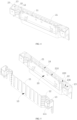
FIG. 4 is a sectional view of the battery module end plate shown inFIG. 2 . -
FIG. 5 is an exploded view of the battery module end plate shown inFIG. 4 . - Reference numerals in the drawings have following meanings:
first plate body 10;first body portion 11;connection surface 110;locking surface 111;avoidance hole 112; first profiledportion 12;first fixing portion 13; opening 14;second plate body 20;second body portion 21;first accommodation space 210; second profiledportion 22;second accommodation space 220;second fixing portion 23;third accommodation space 230;locking hole 231;weight reduction hole 24; batterymodule end plate 100. - In order to facilitate understanding of the present disclosure and to make the above-mentioned objects, features, and advantages of the present disclosure more obvious and comprehensive, a detailed description of specific embodiments of the present disclosure will be given below in conjunction with the accompanying drawings. In the following description, many specific details are provided to facilitate full understanding of the present disclosure. Preferred embodiments of the present disclosure are illustrated by the accompanying drawings. However, the present disclosure can be implemented in many different forms and is not limited to the embodiments described herein. On the contrary, these embodiments are provided to facilitate thorough and comprehensive understanding of the content of the present disclosure. The present disclosure can be implemented in many other ways than those described herein, and similar improvements can be made by those skilled in the art without contradicting the intent of the present disclosure. Therefore, the present disclosure is not limited by specific embodiments disclosed below.
- In the description of the embodiments of the present disclosure, it should be understood that the orientation or the position indicated by terms such as "center", "longitudinal," "lateral," "length," "width," "thickness," "over," "below," "front," "rear," "left," "right," "vertical," "horizontal," "top," "bottom," "inner," "outer," "clockwise," "anticlockwise," "axial," "radial," and "circumferential" should be construed to refer to the orientation and the position as shown in the drawings, and is only for the convenience of describing the embodiments of the present disclosure and simplifying the description, rather than indicating or implying that the pointed device or element must have a specific orientation, or be constructed and operated in a specific orientation, and therefore cannot be understood as a limitation of the present disclosure.
- In addition, terms such as "first" and "second" are only used for descriptive purposes, and cannot be understood as indicating or implying relative importance or implicitly indicating the number of indicated technical features. Therefore, the features associated with "first" and "second" may explicitly or implicitly include at least one of the features. In the description of the embodiments of the present disclosure, "plurality" means at least two, unless otherwise specifically defined.
- In the description of the embodiments of the present disclosure, unless otherwise clearly specified and limited, terms such as "install," "connect," "connect to," "fix" and the like should be understood in a broad sense. For example, it may be a fixed connection or a detachable connection or connection as one piece; mechanical connection or electrical connection; direct connection or indirect connection through an intermediate; internal communication of two components or the interaction relationship between two components. For those of ordinary skill in the art, the specific meaning of the above-mentioned terms in the embodiments of the present disclosure can be understood according to specific circumstances.
- In the description of the embodiments of the present disclosure, unless otherwise expressly specified and defined, the first feature "on" or "under" the second feature may mean that the first feature is in direct contact with the second feature, or the first and second features are in indirect contact through an intermediate. Moreover, the first feature "above" the second feature may mean that the first feature is directly above or obliquely above the second feature, or simply mean that the level of the first feature is higher than that of the second feature. The first feature "below" the second feature may mean that the first feature is directly below or obliquely below the second feature, or simply mean that the level of the first feature is smaller than that of the second feature.
- It should be noted that when an element is "fixed to" or "disposed on" another element, it may be directly on the other element or there may be a centered element. When an element is said to be "attached" to another element, it may be directly attached to the other element or there may be both centered elements. As used herein, the terms "vertical", "horizontal," "top," "bottom," "left," "right," and similar expressions are used herein for illustrative purposes only and are not intended to be the only means of implementation.
- A new energy vehicle generally employs a battery pack as an energy component, and a battery module is a core component of the battery pack. The battery module typically consists of a base plate, a top cover, two side plates, two end plates, and a plurality of battery cells. The base plate, the top cover, the two side plates, and the two end plates are assembled to combine the plurality of battery cells together.
- It has been found that the end plate in the battery module is generally formed by assembling a plurality of metal plates. In an example, a single metal plate is stamped first, and then the plurality of metal plates are fixed together through welding. This would result in a large overall dimensional error and poor structural stability and anti-deformation capability of the end plate. As a result, the end plate cannot resist an expansion force with a high cycle number.
- In order to improve the anti-deformation capability of the end plate in the battery module, a connection stability between the plate bodies is effectively strengthened by integrally molding the plate bodies of the end plate through molding die. In this way, the anti-deformation capability can be improved. Meanwhile, accuracy of an overall dimension of the end plate can be ensured.
-
FIG. 1 is a flowchart of a preparation method for a battery module end plate according to an embodiment of the present disclosure. Referring toFIG. 1 , the preparation method includes operations at blocks S10 to S40. - At
block S 10, a first blank is provided and stamped to obtain afirst plate body 10. - In an exemplary embodiment of the present disclosure, a stamping machine is used to stamp the first blank into the
first plate body 10 of a predetermined shape. The first blank is made of metal such as aluminum or steel. - At block S20, a molding die is provided, and the
first plate body 10 is placed into the molding die. - In an exemplary embodiment of the present disclosure, the molding die has a mold cavity for molding the battery
module end plate 100, and thefirst plate body 10 is placed at a predetermined position in the mold cavity of the molding die. - At block S30, a second blank is provided and melted to obtain a molten material.
- In an exemplary embodiment of the present disclosure, the second blank may be made of metal or plastic, and the metal may be aluminum.
- At block S40, the molten material is injected into the molding die to allow the molten material to be wrapped around the
first plate body 10, and the batterymodule end plate 100 is obtained through cooling.FIG. 2 is a schematic structural view of a battery module end plate according to an embodiment of the present disclosure.FIG. 3 is an exploded view of the battery module end plate shown inFIG. 2 . Referring toFIG. 2 andFIG. 3 , the batterymodule end plate 100 includes thefirst plate body 10 and asecond plate body 20. Thesecond plate body 20 is formed by cooling the molten material and is wrapped around thefirst plate body 10. - In an exemplary embodiment of the present disclosure, when both the first blank and the second blank are made of metal, for example, the first blank is made of aluminum and the second blank is made of steel, the battery
module end plate 100 is molded through die-casting molding after the molten material is injected into the molding die. When the first blank is made of metal such as aluminum, and the second blank is made of plastic, the batterymodule end plate 100 is molded through injection molding after the molten material is injected into the molding die. - In the battery
module end plate 100 prepared by the preparation method for the battery module end plate as described above, thesecond plate body 20 is wrapped around thefirst plate body 10. As a result, thefirst plate body 10 and thesecond plate body 20 are formed integrally. Therefore, an overall structural stability of the battery module end plate can be effectively ensured, which is conducive to improving an overall anti-deformation ability of the battery module end plate and to reducing a deformation amount of the battery module end plate under a high expansion force. Therefore, it is possible to ensure the overall structural stability of the battery module, which in turn effectively ensures that the battery module can be used normally. In addition, in the preparation method, thefirst plate body 10 is first stamped and molded, and then thefirst plate body 10 is placed into the molding die. Then, the melted second blank is injected into the molding die and the batterymodule end plate 100 is obtained through cooling. Therefore, the process is simple, the production efficiency is high, and the cost is low. Moreover, the batterymodule end plate 100 is molded through the molding die, which can effectively ensure the accuracy of the batterymodule end plate 100 and provide high consistency for the batterymodule end plate 100. - Referring to
FIG. 2 , in some embodiments, each of two ends of thefirst plate body 10 has aconnection surface 110, and theconnection surface 110 is an end face of thefirst plate body 10. The connection surface110 is a smooth surface. The connection surfaces 110 are exposed from thesecond plate body 20. In this way, the connection surfaces 110 can be welded to the side plate when the batterymodule end plate 100 is assembled with the side plate. Since thefirst plate body 10 is embedded in thesecond plate body 20 and thefirst plate body 10 is metal, the stiffness of theconnection surface 110 can be effectively ensured. In this way, as the connection surfaces 110 of thefirst plate body 10 are welded to the side plate, the connection stability between the batterymodule end plate 100 and the side plate can be effectively ensured, which in turn ensures the overall stiffness of the battery module. - In some embodiments, the
first plate body 10 further has a lockingsurface 111, and the lockingsurface 111 is adjacent to theconnection surface 110. The lockingsurface 111 is exposed from thesecond plate body 20, and is configured to be connected to an external component. Since the first plate body10 is embedded in thesecond plate body 20 and thefirst plate body 10 is made of metal, stiffness of the lockingsurface 111 can be effectively ensured. - Referring from
FIG. 2 to FIG. 5 , in an exemplary embodiment, thefirst plate body 10 includes afirst body portion 11, two first profiledportions 12, and twofirst fixing portions 13. Thefirst body portion 11 is in a flat plate shape, and each of the two first profiledportions 12 is of an L shape. The two first profiledportions 12 are respectively arranged at two ends of thefirst body portion 11, and the twofirst fixing portions 13 are respectively arranged at ends of the two first profiledportions 12 away from thefirst body portion 11. Each of the first fixingportion 13 is a hollow. A side of each of thefirst fixing portions 13 facing away from the respective first profiledportion 12 is theconnection surface 110, and each of a top surface and a bottom surface of the first fixingportion 13 is the lockingsurface 111. - In some embodiments, the
first plate body 10 has at least oneopening 14. The at least oneopening 14 is filled with a part of the molten material during an injection of the molten material into the molding die. That is, thesecond plate body 20 is partially located in the at least oneopening 14. By forming the at least oneopening 14 on thefirst plate body 10, thesecond plate body 20 is allowed to be partially located in the at least oneopening 14, thereby effectively increasing the bonding force between thefirst plate body 10 and thesecond plate body 20, which in turn ensures anti-deformation strength of the batterymodule end plate 100 in a cycle process of high expansion force. Further, the at least oneopening 14 includes a plurality ofopenings 14. The plurality ofopenings 14 includes some transverse elongated holes, some longitudinal elongated holes, and some circular holes. By providing the plurality ofopenings 14 of different shapes, it is beneficial to further increase the bonding force between thefirst plate body 10 and thesecond plate body 20. In an example, the plurality ofopenings 14 at thefirst body portion 11 is longitudinal elongated holes, and are arranged at intervals in parallel in a transverse direction of thefirst plate body 10. The plurality ofopenings 14 at the second profiledportions 22 is transversely elongated holes, and are arranged at parallel intervals in a longitudinal direction of thefirst plate body 10. Some of the plurality ofopenings 14 at the first fixingportion 13 are transverse elongated holes, and some of the plurality ofopenings 14 at thefirst fixing portions 13 are circular holes. - Referring to
FIG. 3 andFIG. 4 , thesecond plate body 20 has at least oneweight reduction hole 24. The at least oneweight reduction hole 24 is an elongated hole extending in a longitudinal direction of thesecond plate body 20. The at least oneweight reduction hole 24 includes a plurality ofweight reductions 24 arranged at intervals in parallel in a transverse direction of the plurality of weight reduction holes 24. - The
second body plate 20 includes asecond body portion 21, two second profiledportions 22, and twosecond fixing portions 23. Thesecond body portion 21 has afirst accommodation space 210 for accommodating thefirst body portion 11. Theweight reduction 24 is formed at thesecond body portion 21. The two second profiledportions 22 are respectively arranged at two ends of thesecond body portion 21, and each of the two second profiledportions 22 internally has asecond accommodation space 220 for accommodating the first profiledportion 12. It can be understood that the two first profiledportions 12 are respectively accommodated in the respectivesecond accommodation spaces 220 of the two second profiledportions 22. The twosecond fixing portions 23 are respectively arranged at ends of the two second profiledportions 22 away from thesecond body portion 21. Each of thesecond fixing portions 23 internally has athird accommodation space 230 for accommodating the first fixingportion 13. It can be understood that the twofirst fixing portions 13 are respectively accommodated in the respectivethird accommodation spaces 230 of the twofirst fixing portions 13. Further, the connection surfaces 110 and the locking surfaces 111 are exposed from thesecond fixing portions 23. Furthermore, alocking hole 231 is formed at each of the twosecond fixing portions 23. Thelocking hole 231 penetrates a top and a bottom of the second fixingportion 23. The lockingsurface 111 has an avoidance hole112 corresponding to thelocking hole 231. - In some embodiments, after the operation at block S40, the preparation method further includes operations at blocks S50 to S100.
- At block S50, the battery
module end plate 100 is rinsed. After removing the batterymodule end plate 100 from the mold cavity of the molding die, impurities may generally adhere to a surface of the batterymodule end plate 100. Therefore, the impurities on the surface of the batterymodule end plate 100 can be removed by rinsing. - At block S60, the battery
module end plate 100 is polished. In an example, when both thefirst plate body 10 and thesecond plate body 20 are made of metal, a surface of thesecond plate body 20 and a part of thefirst plate body 10 exposed from thesecond plate body 20 are polished. When thefirst plate body 10 is made of metal and thesecond plate body 20 is made of plastic, only the part of thefirst plate body 10 exposed from thesecond plate body 20 is polished. - At block S70, the battery
module end plate 100 is deburred. - At block S80, CNC process is performed on the battery
module end plate 100. In an example, the batterymodule end plate 100 may be micro-machined through the CNC process. For example, slotted holes are machined at the batterymodule end plate 100. - At block S90, the battery module is cleaned. After the CNC process, there are some debris on the battery
module end plate 100, and the debris on the batterymodule end plate 100 can be removed by cleaning the batterymodule end plate 100. - At block S100, the battery module is powder sprayed.
- The present disclosure further provides a battery
module end plate 100 prepared by the preparation method as described above. In an exemplary embodiment, the batterymodule end plate 100 includes afirst plate body 10 and asecond plate body 20 wrapped around thefirst plate body 10. As shown inFIG. 4 , the first blank is made of metal such as aluminum or steel, etc. The second blank may be made of metal or plastic, and the metal may be aluminum. It should be noted that when the first blank is made of steel, the second blank is made of aluminum. When the first blank is made of steel, the second blank is made of aluminum. - Referring to
FIG. 2 , in some embodiments, each of two ends of thefirst plate body 10 has aconnection surface 110, and theconnection surface 110 is an end face of thefirst plate body 10. The connection surface110 is a smooth surface. The connection surfaces 110 are exposed from thesecond plate body 20. Therefore, the connection surfaces 110 can be welded to the side plate when the batterymodule end plate 100 is assembled with the side plate. Since thefirst plate body 10 is embedded in thesecond plate body 20 and thefirst plate body 10 is metal, the stiffness of theconnection surface 110 can be effectively ensured. In this way, as the connection surfaces 110 of thefirst plate body 10 are welded to the side plate, the connection stability between the batterymodule end plate 100 and the side plate can be effectively ensured, which in turn ensures the overall stiffness of the battery module. - In some embodiments, the first plate body10 further has a locking
surface 111, and the lockingsurface 111 is adjacent to theconnection surface 110. The lockingsurface 111 is exposed from thesecond plate body 20, and is configured to be connected to an external component. Since the first plate body10 is embedded in thesecond plate body 20 and thefirst plate body 10 is made of metal, stiffness of the lockingsurface 111 can be effectively ensured. - Referring from
FIG. 2 to FIG. 5 , in an exemplary embodiment, thefirst plate body 10 includes afirst body portion 11, two first profiledportions 12, and two first fixing portions13. Thefirst body portion 11 is in a flat plate shape, and each of the two first profiledportions 12 is in an L shape. The two first profiledportions 12 are respectively arranged at two ends of thefirst body portion 11, and the twofirst fixing portions 13 are respectively arranged at ends of the two first profiledportions 12 away from thefirst body portion 11. Each of thefirst fixing portions 13 is a hollow. A side of each of thefirst fixing portions 13 facing away from the first profiledportion 12 is theconnection surface 110, and each of a top surface and a bottom surface of the first fixingportion 13 are the lockingsurface 111. - In some embodiments, the
first plate body 10 has at least oneopening 14. Thesecond plate body 20 is partially located in the at least oneopening 14. By forming the at least oneopening 14 at thefirst plate body 10, thesecond plate body 20 is allowed to be partially located in the at least oneopening 14, thereby effectively increasing the bonding force between thefirst plate body 10 and thesecond plate body 20, which in turn ensures anti-deformation strength of the batterymodule end plate 100 in a cycle process of high expansion force. Further, the at least oneopening 14 includes a plurality ofopenings 14. The plurality ofopenings 14 includes some transverse elongated holes, some longitudinal elongated holes, and some circular holes. By providing the plurality ofopenings 14 with different shapes, it is beneficial to further increase the bonding force between thefirst plate body 10 and thesecond plate body 20. In an example, the plurality ofopenings 14 at thefirst body portion 11 are longitudinal elongated holes, and are arranged at parallel intervals in a lateral direction of thefirst plate body 10. The plurality ofopenings 14 at the second profiledportions 22 is transversely elongated holes, and is arranged at intervals in parallel in a longitudinal direction of thefirst plate body 10. Some of the plurality ofopenings 14 at thefirst fixing portions 13 is transverse elongated holes, and some of the plurality ofopenings 14 at thefirst fixing portions 13 are circular holes. - Referring to
FIG. 3 andFIG. 4 , thesecond plate body 20 has at least oneweight reduction hole 24. The at least oneweight reduction hole 24 is an elongated hole extending in the longitudinal direction of thesecond plate body 20. The at least oneweight reduction hole 24 includes a plurality ofweight reductions 24 arranged at intervals in parallel in a transverse direction of the plurality of weight reduction holes 24. - The
second body plate 20 includes asecond body portion 21, two second profiledportions 22, and twosecond fixing portions 23. Thesecond body portion 21 has afirst accommodation space 210 for accommodating thefirst body portion 11. The two second profiledportions 22 are respectively arranged at two ends of thesecond body portion 21, and each of the two second profiledportions 22 internally has asecond accommodation space 220 for accommodating the first profiledportion 12. It can be understood that the two first profiledportions 12 are respectively accommodated in the respectivesecond accommodation spaces 220 of the two second profiledportions 22. The twosecond fixing portions 23 are respectively arranged at ends of the two second profiledportions 22 away from thesecond body portion 21. Each of the second fixingportion 23 internally has athird accommodation space 230 for accommodating the first fixingportion 13. It can be understood that the twofirst fixing portions 13 are respectively accommodated in thethird accommodation spaces 230 of the twofirst fixing portions 13. Further, the connection surfaces 110 and the locking surfaces 111 are exposed from thesecond fixing portions 23. Further, alocking hole 231 is formed at each of thesecond fixing portions 23. Thelocking hole 231 penetrates a top and a bottom of the second fixingportion 23. The lockingsurface 111 has an avoidance hole112 corresponding to thelocking hole 231. - In the battery
module end plate 100 prepared by the preparation method according to the above embodiments of the present disclosure, thesecond plate body 20 is wrapped around thefirst plate body 10. As a result, thefirst plate body 10 and thesecond plate body 20 are formed integrally. Therefore, an overall structural stability of the battery module end plate can be effectively ensured, which is conducive to improving an overall anti-deformation capability of the battery module end plate and to reducing a deformation degree of the battery module end plate under a high expansion force. Therefore, it is possible to ensure the overall structural stability of the battery module, which in turn effectively ensures that the battery module can be used normally. In addition, in the preparation method, thefirst plate body 10 is first stamped and molded, and then thefirst plate body 10 is placed into the molding die. Then, the melted second blank is injected into the molding die and the batterymodule end plate 100 is obtained through cooling. Therefore, the process is simple, the production efficiency is high, and the cost is low. Moreover, the batterymodule end plate 100 is molded through the molding die, and thus has good consistency, which can effectively ensure the accuracy of the batterymodule end plate 100. Therefore, it is possible to effectively ensure the dimension accuracy of the connection surfaces 110 and the locking surfaces 111 of the batterymodule end plate 100. - According to embodiments of the present disclosure, a battery module is further provided. The battery module includes the battery module end plate100 as described above. In an exemplary embodiment, two battery
module end plates 100 are provided. The battery module further includes a bottom plate, a cover, two side plates, and a plurality of battery cells. The plurality of battery cells is sequentially connected in series to form a battery pack. The bottom plate is located at a bottom of the battery pack, and the cover is located at a top of the battery pack. The two side plates are located at two sides of the battery pack, respectively. The two batterymodule end plates 100 are located at two ends of the battery pack. Theconnection surface 110 of the batterymodule end plate 100 is welded to an end surface of the side plate. - In order to make the description simple, all possible combinations of the technical features in the foregoing embodiments are not described. However, as long as there is no conflict between the technical features in the embodiments, any combination of technical features in the above-described embodiments may be adopted, which should be considered to be fallen within the scope of the present disclosure.
- The above embodiments illustrate merely some implementations of the present disclosure, which are described in detail but are not construed to limit the scope of the present disclosure. It should be noted for those of ordinary skill in the art that various changes and improvements may be made without departing from the principle of the present disclosure, which are all fallen within the scope of the present disclosure. Therefore, the scope of the present disclosure shall be defined by the appended claims.
Claims (10)
- A preparation method for a battery module end plate (100), characterized in that:the preparation method comprises:providing a first blank and stamping the first blank to obtain a first plate body (10);providing a molding die and placing the first plate body (10) into the molding die;providing a second blank and melting the second blank to obtain a molten material; andinjecting the molten material into the molding die to allow the molten material to be wrapped around the first plate body (10), and obtaining the battery module end plate (100) through cooling, wherein:
the battery module end plate (100) comprises the first plate body (10) and a second plate body (20), the second plate body (20) being formed by cooling the molten material and wrapped around the first plate body (10). - The preparation method for a battery module end plate (100) according to claim 1, wherein:the first blank is made of metal; and/orthe second blank is made of metal or plastic.
- The preparation method for a battery module end plate (100) according to claim 2, wherein when both the first blank and the second blank are made of metal, the battery module end plate (100) is molded through die-casting molding after the molten material is injected into the molding die.
- The preparation method for a battery module end plate (100) according to claim 2 or 3, wherein when the first blank is made of metal and the second blank is made of plastic, the battery module end plate (100) is molded through injection molding after the molten material is injected into the molding die.
- The preparation method for a battery module end plate (100) according to any one of claims 2 to 4, wherein each of two ends of the first plate body (10) has a connection surface (110) exposed from the second plate body (20).
- The preparation method for a battery module end plate (100) according to any one of claims 2 to 5, wherein the first plate body (10) further has a locking surface (111) exposed from the second plate body (20).
- The preparation method for a battery module end plate (100) according to any one of claims 1 to 6, wherein the first plate body (10) has at least one opening (14), the at least one opening (14) being filled with a part of the molten material during an injection of the molten material into the molding die.
- The preparation method for a battery module end plate (100) according to claim 7, wherein the at least one opening (14) comprises a plurality of openings (14), including some transverse elongated holes, some longitudinal elongated holes, and some circular holes.
- A battery module end plate (100), being prepared by the preparation method according to any one of claims 1 to 8.
- A battery module, comprising the battery module end plate (100) according to claim 9.
Applications Claiming Priority (2)
| Application Number | Priority Date | Filing Date | Title |
|---|---|---|---|
| CN202111209371.7A CN115832554B (en) | 2021-10-18 | 2021-10-18 | Battery module end plate, battery module, and method for preparing battery module end plate |
| PCT/CN2022/125642 WO2023066191A1 (en) | 2021-10-18 | 2022-10-17 | Battery module end plate, battery module, and preparation method for battery module end plate |
Publications (2)
| Publication Number | Publication Date |
|---|---|
| EP4354612A1 true EP4354612A1 (en) | 2024-04-17 |
| EP4354612A4 EP4354612A4 (en) | 2025-03-19 |
Family
ID=85515413
Family Applications (1)
| Application Number | Title | Priority Date | Filing Date |
|---|---|---|---|
| EP22882797.8A Pending EP4354612A4 (en) | 2021-10-18 | 2022-10-17 | Battery module end plate, battery module, and preparation method for battery module end plate |
Country Status (4)
| Country | Link |
|---|---|
| US (1) | US20240213612A1 (en) |
| EP (1) | EP4354612A4 (en) |
| CN (1) | CN115832554B (en) |
| WO (1) | WO2023066191A1 (en) |
Family Cites Families (13)
| Publication number | Priority date | Publication date | Assignee | Title |
|---|---|---|---|---|
| TW201108909A (en) * | 2009-08-21 | 2011-03-01 | Fih Hong Kong Ltd | Housing of portable electric device and method for making same |
| CN204271149U (en) * | 2014-10-10 | 2015-04-15 | 宁德时代新能源科技有限公司 | A kind of end plate of composite construction and comprise the battery modules of this end plate |
| CN106827374A (en) * | 2016-10-31 | 2017-06-13 | 东莞劲胜精密组件股份有限公司 | A kind of casting integrated its shaping process of metal insert |
| CN206250253U (en) * | 2016-12-27 | 2017-06-13 | 宁德时代新能源科技股份有限公司 | Battery modules end plate and battery modules |
| CN207441797U (en) * | 2017-10-26 | 2018-06-01 | 宁德时代新能源科技股份有限公司 | A kind of battery modules end plate and battery modules |
| CN109994696B (en) * | 2017-12-29 | 2020-12-08 | 宁德时代新能源科技股份有限公司 | Composite end plate and battery module |
| CN109994666B (en) * | 2017-12-29 | 2020-11-06 | 宁德时代新能源科技股份有限公司 | Composite end plate and battery module |
| CN208923254U (en) * | 2018-12-14 | 2019-05-31 | 蜂巢能源科技有限公司 | End plate, battery pack and the automobile of battery modules |
| CN110238517B (en) * | 2019-05-24 | 2022-04-01 | 宁波旭升汽车技术股份有限公司 | Laser welding process for aluminum alloy die-casting insert |
| CN211629155U (en) * | 2019-12-27 | 2020-10-02 | 芜湖天量电池系统有限公司 | A composite module end plate |
| CN212874637U (en) * | 2020-06-05 | 2021-04-02 | 欣旺达电动汽车电池有限公司 | End plate and battery module |
| CN213278221U (en) * | 2020-09-01 | 2021-05-25 | 东莞汇洋动力科技有限公司 | Battery module end plate, battery module and battery pack |
| CN112496306A (en) * | 2020-11-30 | 2021-03-16 | 富钛金属科技(昆山)有限公司 | Preparation method of battery end plate with insert |
-
2021
- 2021-10-18 CN CN202111209371.7A patent/CN115832554B/en active Active
-
2022
- 2022-10-17 WO PCT/CN2022/125642 patent/WO2023066191A1/en not_active Ceased
- 2022-10-17 EP EP22882797.8A patent/EP4354612A4/en active Pending
-
2024
- 2024-03-11 US US18/600,783 patent/US20240213612A1/en active Pending
Also Published As
| Publication number | Publication date |
|---|---|
| CN115832554B (en) | 2024-10-18 |
| CN115832554A (en) | 2023-03-21 |
| WO2023066191A1 (en) | 2023-04-27 |
| EP4354612A4 (en) | 2025-03-19 |
| US20240213612A1 (en) | 2024-06-27 |
Similar Documents
| Publication | Publication Date | Title |
|---|---|---|
| JP7576653B2 (en) | Method for integrally pressing top cover plate and method for manufacturing top cover structure | |
| JP5755101B2 (en) | Battery holding structure | |
| EP2429019B1 (en) | Lead-acid battery and method for manufacturing current collector for lead-acid battery | |
| JPH10172536A (en) | Corrosion-resistant battery terminals with short fixing parts without alignment streaks | |
| EP4354612A1 (en) | Battery module end plate, battery module, and preparation method for battery module end plate | |
| CN221961100U (en) | Battery cell and battery pack | |
| EP4258428A1 (en) | Battery casing and lithium battery | |
| US8734969B2 (en) | Dummy cell for battery pack and molding apparatus for manufacturing battery pack | |
| CN213163027U (en) | Ceramic composite prefabricated body structure | |
| CN212707710U (en) | Steering gear hollow rack internal expanding extrusion forming processing device | |
| CN222491970U (en) | Forging structure of partition piece | |
| CN116709692A (en) | Middle frame, middle frame manufacturing method and electronic equipment | |
| CN213437119U (en) | A versatile casting and welding mold for battery busbars | |
| CN210848267U (en) | High-precision die-casting die for aluminum alloy shell | |
| CN222792364U (en) | Jig integrating ferrite structure and deburring | |
| CN223436543U (en) | Shelf assemblies and restraint trays | |
| CN218906166U (en) | High-precision automobile handle die | |
| CN223198016U (en) | Spring seat blank, sand mould and casting mould | |
| CN221247427U (en) | Preformed soldering lug for preventing lack of soldering | |
| CN216230304U (en) | Automobile thin-wall fender rear cover die | |
| JP7770430B2 (en) | Lower plastic, battery, battery module and power consumption device | |
| CN215392337U (en) | A bolster core with a new structure that is easy to feed and clean up the riser | |
| CN223167592U (en) | Battery module end plate assembly, battery module and battery pack | |
| CN222980688U (en) | Battery pack and vehicle | |
| EP4604284A1 (en) | Method of manufacturing electricity storage device case component, electricity storage device case component, and electricity storage device |
Legal Events
| Date | Code | Title | Description |
|---|---|---|---|
| STAA | Information on the status of an ep patent application or granted ep patent |
Free format text: STATUS: THE INTERNATIONAL PUBLICATION HAS BEEN MADE |
|
| PUAI | Public reference made under article 153(3) epc to a published international application that has entered the european phase |
Free format text: ORIGINAL CODE: 0009012 |
|
| STAA | Information on the status of an ep patent application or granted ep patent |
Free format text: STATUS: REQUEST FOR EXAMINATION WAS MADE |
|
| 17P | Request for examination filed |
Effective date: 20240111 |
|
| AK | Designated contracting states |
Kind code of ref document: A1 Designated state(s): AL AT BE BG CH CY CZ DE DK EE ES FI FR GB GR HR HU IE IS IT LI LT LU LV MC ME MK MT NL NO PL PT RO RS SE SI SK SM TR |
|
| RAP1 | Party data changed (applicant data changed or rights of an application transferred) |
Owner name: CONTEMPORARY AMPEREX TECHNOLOGY(HONG KONG) LIMITED |
|
| DAV | Request for validation of the european patent (deleted) | ||
| DAX | Request for extension of the european patent (deleted) | ||
| A4 | Supplementary search report drawn up and despatched |
Effective date: 20250219 |
|
| RIC1 | Information provided on ipc code assigned before grant |
Ipc: H01M 50/242 20210101ALI20250213BHEP Ipc: H01M 50/227 20210101ALI20250213BHEP Ipc: B29C 45/14 20060101ALI20250213BHEP Ipc: B22D 19/00 20060101ALI20250213BHEP Ipc: H01M 50/204 20210101AFI20250213BHEP |