EP4354593A1 - Battery for an electrical or hybrid vehicle, comprising loop or oscillating heat pipes, or heat pipes - Google Patents
Battery for an electrical or hybrid vehicle, comprising loop or oscillating heat pipes, or heat pipes Download PDFInfo
- Publication number
- EP4354593A1 EP4354593A1 EP22306539.2A EP22306539A EP4354593A1 EP 4354593 A1 EP4354593 A1 EP 4354593A1 EP 22306539 A EP22306539 A EP 22306539A EP 4354593 A1 EP4354593 A1 EP 4354593A1
- Authority
- EP
- European Patent Office
- Prior art keywords
- plate
- battery
- heat
- cooling system
- stack
- Prior art date
- Legal status (The legal status is an assumption and is not a legal conclusion. Google has not performed a legal analysis and makes no representation as to the accuracy of the status listed.)
- Pending
Links
Images


Classifications
-
- H—ELECTRICITY
- H01—ELECTRIC ELEMENTS
- H01M—PROCESSES OR MEANS, e.g. BATTERIES, FOR THE DIRECT CONVERSION OF CHEMICAL ENERGY INTO ELECTRICAL ENERGY
- H01M10/00—Secondary cells; Manufacture thereof
- H01M10/60—Heating or cooling; Temperature control
- H01M10/61—Types of temperature control
- H01M10/613—Cooling or keeping cold
-
- F—MECHANICAL ENGINEERING; LIGHTING; HEATING; WEAPONS; BLASTING
- F28—HEAT EXCHANGE IN GENERAL
- F28D—HEAT-EXCHANGE APPARATUS, NOT PROVIDED FOR IN ANOTHER SUBCLASS, IN WHICH THE HEAT-EXCHANGE MEDIA DO NOT COME INTO DIRECT CONTACT
- F28D15/00—Heat-exchange apparatus with the intermediate heat-transfer medium in closed tubes passing into or through the conduit walls ; Heat-exchange apparatus employing intermediate heat-transfer medium or bodies
- F28D15/02—Heat-exchange apparatus with the intermediate heat-transfer medium in closed tubes passing into or through the conduit walls ; Heat-exchange apparatus employing intermediate heat-transfer medium or bodies in which the medium condenses and evaporates, e.g. heat pipes
- F28D15/0266—Heat-exchange apparatus with the intermediate heat-transfer medium in closed tubes passing into or through the conduit walls ; Heat-exchange apparatus employing intermediate heat-transfer medium or bodies in which the medium condenses and evaporates, e.g. heat pipes with separate evaporating and condensing chambers connected by at least one conduit; Loop-type heat pipes; with multiple or common evaporating or condensing chambers
-
- H—ELECTRICITY
- H01—ELECTRIC ELEMENTS
- H01M—PROCESSES OR MEANS, e.g. BATTERIES, FOR THE DIRECT CONVERSION OF CHEMICAL ENERGY INTO ELECTRICAL ENERGY
- H01M10/00—Secondary cells; Manufacture thereof
- H01M10/60—Heating or cooling; Temperature control
- H01M10/61—Types of temperature control
- H01M10/617—Types of temperature control for achieving uniformity or desired distribution of temperature
-
- H—ELECTRICITY
- H01—ELECTRIC ELEMENTS
- H01M—PROCESSES OR MEANS, e.g. BATTERIES, FOR THE DIRECT CONVERSION OF CHEMICAL ENERGY INTO ELECTRICAL ENERGY
- H01M10/00—Secondary cells; Manufacture thereof
- H01M10/60—Heating or cooling; Temperature control
- H01M10/62—Heating or cooling; Temperature control specially adapted for specific applications
- H01M10/625—Vehicles
-
- H—ELECTRICITY
- H01—ELECTRIC ELEMENTS
- H01M—PROCESSES OR MEANS, e.g. BATTERIES, FOR THE DIRECT CONVERSION OF CHEMICAL ENERGY INTO ELECTRICAL ENERGY
- H01M10/00—Secondary cells; Manufacture thereof
- H01M10/60—Heating or cooling; Temperature control
- H01M10/64—Heating or cooling; Temperature control characterised by the shape of the cells
- H01M10/647—Prismatic or flat cells, e.g. pouch cells
-
- H—ELECTRICITY
- H01—ELECTRIC ELEMENTS
- H01M—PROCESSES OR MEANS, e.g. BATTERIES, FOR THE DIRECT CONVERSION OF CHEMICAL ENERGY INTO ELECTRICAL ENERGY
- H01M10/00—Secondary cells; Manufacture thereof
- H01M10/60—Heating or cooling; Temperature control
- H01M10/65—Means for temperature control structurally associated with the cells
- H01M10/655—Solid structures for heat exchange or heat conduction
- H01M10/6552—Closed pipes transferring heat by thermal conductivity or phase transition, e.g. heat pipes
-
- H—ELECTRICITY
- H01—ELECTRIC ELEMENTS
- H01M—PROCESSES OR MEANS, e.g. BATTERIES, FOR THE DIRECT CONVERSION OF CHEMICAL ENERGY INTO ELECTRICAL ENERGY
- H01M10/00—Secondary cells; Manufacture thereof
- H01M10/60—Heating or cooling; Temperature control
- H01M10/65—Means for temperature control structurally associated with the cells
- H01M10/655—Solid structures for heat exchange or heat conduction
- H01M10/6554—Rods or plates
-
- H—ELECTRICITY
- H01—ELECTRIC ELEMENTS
- H01M—PROCESSES OR MEANS, e.g. BATTERIES, FOR THE DIRECT CONVERSION OF CHEMICAL ENERGY INTO ELECTRICAL ENERGY
- H01M10/00—Secondary cells; Manufacture thereof
- H01M10/60—Heating or cooling; Temperature control
- H01M10/65—Means for temperature control structurally associated with the cells
- H01M10/655—Solid structures for heat exchange or heat conduction
- H01M10/6556—Solid parts with flow channel passages or pipes for heat exchange
- H01M10/6557—Solid parts with flow channel passages or pipes for heat exchange arranged between the cells
-
- H—ELECTRICITY
- H01—ELECTRIC ELEMENTS
- H01M—PROCESSES OR MEANS, e.g. BATTERIES, FOR THE DIRECT CONVERSION OF CHEMICAL ENERGY INTO ELECTRICAL ENERGY
- H01M10/00—Secondary cells; Manufacture thereof
- H01M10/60—Heating or cooling; Temperature control
- H01M10/65—Means for temperature control structurally associated with the cells
- H01M10/656—Means for temperature control structurally associated with the cells characterised by the type of heat-exchange fluid
- H01M10/6561—Gases
- H01M10/6562—Gases with free flow by convection only
-
- H—ELECTRICITY
- H01—ELECTRIC ELEMENTS
- H01M—PROCESSES OR MEANS, e.g. BATTERIES, FOR THE DIRECT CONVERSION OF CHEMICAL ENERGY INTO ELECTRICAL ENERGY
- H01M10/00—Secondary cells; Manufacture thereof
- H01M10/60—Heating or cooling; Temperature control
- H01M10/65—Means for temperature control structurally associated with the cells
- H01M10/656—Means for temperature control structurally associated with the cells characterised by the type of heat-exchange fluid
- H01M10/6567—Liquids
- H01M10/6568—Liquids characterised by flow circuits, e.g. loops, located externally to the cells or cell casings
-
- H—ELECTRICITY
- H01—ELECTRIC ELEMENTS
- H01M—PROCESSES OR MEANS, e.g. BATTERIES, FOR THE DIRECT CONVERSION OF CHEMICAL ENERGY INTO ELECTRICAL ENERGY
- H01M10/00—Secondary cells; Manufacture thereof
- H01M10/60—Heating or cooling; Temperature control
- H01M10/65—Means for temperature control structurally associated with the cells
- H01M10/656—Means for temperature control structurally associated with the cells characterised by the type of heat-exchange fluid
- H01M10/6569—Fluids undergoing a liquid-gas phase change or transition, e.g. evaporation or condensation
-
- H—ELECTRICITY
- H01—ELECTRIC ELEMENTS
- H01M—PROCESSES OR MEANS, e.g. BATTERIES, FOR THE DIRECT CONVERSION OF CHEMICAL ENERGY INTO ELECTRICAL ENERGY
- H01M50/00—Constructional details or processes of manufacture of the non-active parts of electrochemical cells other than fuel cells, e.g. hybrid cells
- H01M50/10—Primary casings; Jackets or wrappings
- H01M50/102—Primary casings; Jackets or wrappings characterised by their shape or physical structure
- H01M50/103—Primary casings; Jackets or wrappings characterised by their shape or physical structure prismatic or rectangular
-
- H—ELECTRICITY
- H01—ELECTRIC ELEMENTS
- H01M—PROCESSES OR MEANS, e.g. BATTERIES, FOR THE DIRECT CONVERSION OF CHEMICAL ENERGY INTO ELECTRICAL ENERGY
- H01M50/00—Constructional details or processes of manufacture of the non-active parts of electrochemical cells other than fuel cells, e.g. hybrid cells
- H01M50/20—Mountings; Secondary casings or frames; Racks, modules or packs; Suspension devices; Shock absorbers; Transport or carrying devices; Holders
- H01M50/204—Racks, modules or packs for multiple batteries or multiple cells
- H01M50/207—Racks, modules or packs for multiple batteries or multiple cells characterised by their shape
- H01M50/209—Racks, modules or packs for multiple batteries or multiple cells characterised by their shape adapted for prismatic or rectangular cells
-
- H—ELECTRICITY
- H01—ELECTRIC ELEMENTS
- H01M—PROCESSES OR MEANS, e.g. BATTERIES, FOR THE DIRECT CONVERSION OF CHEMICAL ENERGY INTO ELECTRICAL ENERGY
- H01M10/00—Secondary cells; Manufacture thereof
- H01M10/05—Accumulators with non-aqueous electrolyte
- H01M10/052—Li-accumulators
-
- Y—GENERAL TAGGING OF NEW TECHNOLOGICAL DEVELOPMENTS; GENERAL TAGGING OF CROSS-SECTIONAL TECHNOLOGIES SPANNING OVER SEVERAL SECTIONS OF THE IPC; TECHNICAL SUBJECTS COVERED BY FORMER USPC CROSS-REFERENCE ART COLLECTIONS [XRACs] AND DIGESTS
- Y02—TECHNOLOGIES OR APPLICATIONS FOR MITIGATION OR ADAPTATION AGAINST CLIMATE CHANGE
- Y02E—REDUCTION OF GREENHOUSE GAS [GHG] EMISSIONS, RELATED TO ENERGY GENERATION, TRANSMISSION OR DISTRIBUTION
- Y02E60/00—Enabling technologies; Technologies with a potential or indirect contribution to GHG emissions mitigation
- Y02E60/10—Energy storage using batteries
Definitions
- the present invention deals with a battery for an electrical or hybrid vehicle, the battery having internal cooling means.
- battery means a plurality of electrochemical cells electrically connected to each other.
- the plurality of electrochemical cells is arranged in the form of one or more module(s), each module comprising several electrochemical cells electrically connected to each other and mechanically assembled to each other by a system of assembly, such as assembly plates.
- An electrochemical cell comprises, in particular, a plurality of positive electrodes intertwined with negative electrodes and separators, known as a "stack". The positive electrodes are connected to each other and to a positive terminal of the cell, and the negative electrodes are connected to each other and to a negative terminal of the cell.
- the battery When the battery operates, in particular during charging, it may produce excessive heat which has to be evacuated in order to avoid damaging the battery elements or risking a thermal runaway of the battery.
- An aim of the invention is to solve or improve the above issues, in particular to avoid hot spots or strong temperature gradients in the battery cells, while keeping the battery compact (with a high energy density) and at an interesting cost.
- the invention proposes a battery for an electrical or hybrid vehicle, the battery comprising:
- the battery comprises one or several of the following features, taken in isolation or any technically feasible combination:
- the invention also deals with a process for cooling a battery comprising:
- the battery 10 is for example intended for an electrical or hybrid vehicle (not shown).
- the battery 10 is partially represented. For example, a general casing, potential crossbeams or other assembly elements, and electrical contacts, which may be present in the battery 10, are not shown.
- the battery 10 comprises a cooling plate 12 extending along a first direction X and a second direction Y perpendicular to the first direction X, and at least a set of electrochemical cells 14A, 14B, 14C extending successively along the second direction Y.
- the first direction X and the second direction Y are for example horizontal.
- the first direction X is for example the longitudinal (driving) direction of the vehicle.
- a third direction Z is also defined as perpendicular to the first direction X and to the second direction Y.
- the third direction Z is for example approximately vertical when the vehicle moves horizontally.
- the battery 10 also comprises an active cooling system 16 adapted for extracting heat from the cooling plate 12.
- the cooling system 16 includes an energy consuming device (not shown), for example a pump, to displace a refrigerant fluid (not shown) of the cooling system.
- an energy consuming device for example a pump
- the refrigerant fluid is adapted for circulating in the cooling plate 12.
- the battery 10 does not include an active cooling system to cool the cooling plate 12, but instead a passive one (not shown), such as cooling fins.
- the battery 10 also comprises two end plates 18, 20.
- the cooling plate 12 is for example located at the bottom of the battery 10.
- the cooling plate 12 may be part of a general casing (not shown) of the battery, or may be separate from a general casing.
- the cooling plate 12 is in thermal contact, preferably in physical plane contact, with each of the electrochemical cells 14A, 14B, 14C and adapted for receiving heat from the electrochemical cells.
- the electrochemical cells 14A, 14B, 14C of the set are structurally analogous to each other, so only the electrochemical cell 14B will be described hereafter.
- the electrochemical cell 14B includes at least a stack 22 of electrochemical elements, an electrolyte 23, and a casing 24 surrounding the stack 22 and the electrolyte 23 and comprising a first part 26 and a second part 28 opposite each other in the second direction Y ( Figures 1 to 3 ), and a third part 30 and a fourth part 32 opposite each other in the third direction Z.
- the electrochemical cell 14B comprises a first plate 34 advantageously formed by the first part 26, and a second plate 36 advantageously formed by the third part 30, the first plate and the second plate being in thermal contact with the stack 22 and the electrolyte 23 and adapted for receiving heat from the stack 22 or the electrolyte 23.
- the electrochemical cell 14B advantageously comprises at least a phase change material 38 within the first plate 34 and the second plate 36.
- the electrochemical cell 14B comprises a first passive cooling system 40 comprising at least a loop heat pipe 42 having an evaporator 44 located in the first plate 34 and a condenser 46 located in the second plate 36.
- the phase change material 38 fills the remaining space in the first plate 34 and the second plate 36 (around the first passive cooling system 40).
- the first part 26 and the second part 28 are for example parallel to each other, and the third part 30 and the fourth part 32 are for example parallel to each other.
- the casing 24 for example has a parallelepiped shape.
- the first plate 34 and the second plate 36 are adapted for receiving heat from the stack 22 and the electrolyte 23, the cooling plate 12 being in thermal contact with the second plate 36 and adapted for receiving heat from the second plate.
- the first plate 34 and the second plate 36 are for example rectangular, and advantageously perpendicular to each other.
- the first plate 34 of one of said electrochemical two cells is in thermal contact, and preferably in plane contact, with the second part 28 of the casing of the other one of said two electrochemical cells.
- the electrochemical cells 14A, 14B, 14C are in thermal contact two by two. This allows the first plate 34 of the electrochemical cells 14B, 14C absorbing heat from the casing 24 of the neighboring electrochemical cells 14A, 14B respectively.
- the first plate 34 and the second plate 36 comprise an internal wall 48 and an external wall 50 with respect to the stack 22 and the electrolyte 23, the internal wall and the external wall defining, between themselves, an inner volume 52 extending in the first plate 34 and in the second plate 36.
- first plate 34 and the second plate 36 considered as a whole, comprise another wall 54 extending along a path 56 of a fluid 58 of the loop heat pipe 42.
- the first plate 34 has a thickness E1 along the second direction Y
- the second part 28 has a thickness E2 along the second direction Y, the thickness E1 being larger than the thickness E2.
- the second plate 36 has a thickness E3 along the third direction Z
- the fourth part 32 has a thickness E4 along the third direction Z, the thickness E3 being larger than the thickness E4 of the fourth part.
- the thicknesses E1 and E3 are for example comprised between 4mm and 8mm.
- the thicknesses E2 and E4 are for example comprised between 0.2mmmm and 3mm.
- the thicknesses E2 and E4 are for example about 0.6mm.
- the first plate 34 and the second plate 36 are not formed by the first part 26 and the third part 30 of the casing 24.
- the first plate 34 and the second plate 36 may be distinct the casing 24, and both in plane contact with the first part 26 and the third part 30 respectively.
- the first plate 34 and the second plate 36 altogether for example have an L-shape in view along the first direction X, and are advantageously integral with each other. In this case, the first plate 34 and the second plate 36 are in indirect thermal contact with the stack 22 and the electrolyte 23 via the casing 24.
- the other wall 54 for example has a U-shaped cross-section perpendicularly to the path 56, and is fixed to the internal wall 48, or as a variant (not shown) to the external wall 50, so as to form a duct 60 for the fluid 58.
- the phase change material 38 advantageously extends in the inner volume 52 in the first plate 34 and in the second plate 36.
- the phase change material 38 has a melting temperature comprised between 10°C and 120°C, preferably between 10°C and 40°C.
- the phase change material 38 comprises n-octadecane, n-nonadecane, or n-eicosane.
- the first passive cooling system 40 comprises at least a heat pipe or an oscillating heat pipe instead of, or in addition to, the loop heat pipe 42.
- the first passive cooling system 40 may comprise several loop heat pipes and/or several oscillating heat pipes and/or several heat pipes.
- Loop heat pipes, oscillating heat pipes and heat pipes are known in themselves and will not be described in detail. They include a phase change fluid circulating between an evaporator region, where the fluid receives heat, and a condenser region, where the fluid releases heat. Loop heat pipes, oscillating heat pipes and heat pipes are passive heat transporting systems, since the fluid circulation is obtained only via temperature differences and sometimes capillarity. In an oscillating heat pipe, the fluid comprises slugs of liquid and vapor in a continuous loop. Loop heat pipes and oscillating heat pipes may include fins in their evaporator and condenser regions.
- the evaporator 44 is adapted for absorbing heat from the first plate 34
- the condenser 46 is adapted for releasing heat to the second plate 36.
- the evaporator 44 extends in a portion 62 of the first plate 34, said portion being closer to the fourth part 32 than to the third part 30 along the third direction Z.
- the first passive cooling system 40 comprises the duct 60 and the fluid 58.
- the fluid 58 is adapted for circulating in the duct 60 from the evaporator 44 to the condenser 46, and from the condenser to the evaporator.
- the duct 60 for example comprises, in the evaporator 44 and the condenser 46, successive sections 64 from a fluid circulation point of view, and U-shaped sections 66 in view along the second direction Y.
- the successive sections 64 for example extend along the first direction X and are connected to each other by the U-shaped sections 66.
- the operation of the battery 10 stems from its structure and will be briefly described in order to illustrate a process according to the invention.
- phase change material 38 advantageously present in the inner volume 52 in the first plate 34 and the second plate 36 makes sure that temperature does not go too high in each electrochemical cell, by absorbing some of the heat due to a phase change.
- the presence of the first passive cooling system 40 ensures that the PCM does not change its phase quickly by carrying out that excessive heat towards the cooling plate 12.
- Heat is also absorbed by the evaporator 44 from the first plate 34. Heat is released by the condenser 44 to the second plate 36, and heat is received by the cooling plate 12 from the second plate 36.
- Heat is then evacuated from the cooling plate 12 for example by the cooling system 16.
- the phase change material 38 advantageously acts as a passive cooling system in order to prevent the temperature from raising when heat is released in the electrochemical cells 14A, 14B, 14C.
- the first passive cooling system 40 thanks to the loop heat pipe 42, the oscillating heat pipe or the heat pipe, is able to convey heat from the first plate 34 to the second plate 36, the heat being then absorbed by the cooling plate 12.
- the phase change material 38 and the first passive cooling system 40 manage to keep the temperature more homogenous than in prior art batteries, in particular in the top part of the electrochemical cells 14A, 14B, 14C.
- the homogenous temperature distribution helps reducing degradation in the battery 10, for example by reducing lithium plating. It increases the life of the battery 10.
- phase change material 38 and the first passive cooling system 40 being both passive, are unlikely to fail.
- first plate 34 and the second plate 36 are formed by the casing 24 is particularly interesting in terms of compactness.
- the first plate 34 of one electrochemical cell can absorb heat from the second part 28 of the casing 24 of a neighboring electrochemical cell.
- the first passive cooling system 40 is able to extract excess heat where it more likely to appear, i.e. away from the cooling plate 12.
- the casing 24 surrounding the stack 22 and the electrolyte 23 comprises a first part 68 and a second part 70 that are opposite each other in the first direction X, and not in the second direction Y.
- the electrochemical cell 14B includes a first plate 72 either formed by the first part 68 or in plane contact with the first part, the first plate 72 being in thermal contact with the stack 22 and adapted for receiving heat from the stack.
- the electrochemical cell 14B comprises a first passive cooling system 74 comprising at least a heat pipe 76, the first passive cooling system comprising an evaporator 78 located in the first plate 72 and adapted for absorbing heat from the first plate, and a condenser 80 located in the second plate 36 and adapted for releasing heat to the second plate.
- the electrochemical cell 14B further includes a third plate 82 either formed by the second part 70 or in plane contact with the second part, the third plate being in thermal contact with the stack 22 and the electrolyte 23 adapted for receiving heat from the stack and the electrolyte.
- the electrochemical cell 14B further comprises a second passive cooling system 84 comprising at least a heat pipe 86, the second passive cooling system comprising an evaporator 88 located in the third plate 82 and adapted for absorbing heat from the third plate, and a condenser 90 located in the second plate 36 and adapted for releasing heat to the second plate.
- a second passive cooling system 84 comprising at least a heat pipe 86, the second passive cooling system comprising an evaporator 88 located in the third plate 82 and adapted for absorbing heat from the third plate, and a condenser 90 located in the second plate 36 and adapted for releasing heat to the second plate.
- the electrochemical cell 14B may comprise a phase change material (not represented) in the first plate 72 and/or in the third plate 82.
- first passive cooling system 74 and the second passive cooling system 84 are structurally analogous to each other. Only the first passive cooling system 74 will be described.
- Heat pipes are known in themselves and will not be described in detail. They include a phase change fluid circulating between an evaporator region, where the fluid receives heat, and a condenser region, where the fluid releases heat.
- the fluid circulation is obtained only via temperature differences and sometimes capillarity.
- the heat pipe 76 of the first passive cooling system 74 comprises a duct 92 and a fluid 94 adapted for circulating in the duct.
- the duct 92 has a section 96 in the condenser 80, said section extending in the first direction X, and a U-shaped section 98 in view along the first direction X.
- the U-shaped section 98 is located the evaporator 78, the "U" of the U-shaped section having a base 100 pointing away from the third part 30 in the third direction Z.
- the evaporator 78 extends in a portion 102 of the first plate 72, said portion being closer to the fourth part 32 than to the third part along the third direction Z.
- the first passive cooling system 74 operates in the same manner as the first passive cooling system 40 shown in figure 3 , by receiving heat from the first plate 72 and releasing heat to the second plate 36.
Landscapes
- Engineering & Computer Science (AREA)
- Chemical & Material Sciences (AREA)
- Chemical Kinetics & Catalysis (AREA)
- Electrochemistry (AREA)
- General Chemical & Material Sciences (AREA)
- Manufacturing & Machinery (AREA)
- Life Sciences & Earth Sciences (AREA)
- Sustainable Development (AREA)
- Physics & Mathematics (AREA)
- Thermal Sciences (AREA)
- Mechanical Engineering (AREA)
- General Engineering & Computer Science (AREA)
- Secondary Cells (AREA)
Abstract
Description
- The present invention deals with a battery for an electrical or hybrid vehicle, the battery having internal cooling means.
- It also deals with a process for cooling such a battery.
- The term "battery" means a plurality of electrochemical cells electrically connected to each other. According to a particular example of battery, the plurality of electrochemical cells is arranged in the form of one or more module(s), each module comprising several electrochemical cells electrically connected to each other and mechanically assembled to each other by a system of assembly, such as assembly plates. An electrochemical cell comprises, in particular, a plurality of positive electrodes intertwined with negative electrodes and separators, known as a "stack". The positive electrodes are connected to each other and to a positive terminal of the cell, and the negative electrodes are connected to each other and to a negative terminal of the cell.
- When the battery operates, in particular during charging, it may produce excessive heat which has to be evacuated in order to avoid damaging the battery elements or risking a thermal runaway of the battery.
- Generally, large cooling plates are installed at the bottom of the modules in most of automotive applications. Heat is removed from the bottom of the battery, whereas its top side remains dependent on the bottom cooling plate. This creates a huge temperature gradient, with a risk of hot spots in some of the electrochemical cells.
- While there are also some cases where cooling plates are installed in between the battery cells, these cases need extra fluid circulation and pump power to circulate the liquid in order to remove the heat. However, these solutions are either expensive or unable to provide a temperature distribution in battery cells that is homogenous enough, in particular when the battery undergoes a fast charge.
- An aim of the invention is to solve or improve the above issues, in particular to avoid hot spots or strong temperature gradients in the battery cells, while keeping the battery compact (with a high energy density) and at an interesting cost.
- To this end, the invention proposes a battery for an electrical or hybrid vehicle, the battery comprising:
- a cooling plate extending along a first direction and a second direction perpendicular to the first direction, and
- at least a set of electrochemical cells extending successively along the second direction,
- at least a stack of electrochemical elements and an electrolyte,
- a casing surrounding the stack and the electrolyte, and comprising a first part and a second part opposite each other in one of the second direction and the first direction, and a third part and a fourth part opposite each other in a third direction perpendicular to the first direction and to the second direction,
- a first plate either formed by the first part, or in plane contact with the first part, the first plate being in thermal contact with the stack and the electrolyte and adapted for receiving heat from the stack and the electrolyte,
- a second plate either formed by the third part, or in plane contact with the third part, the second plate being in thermal contact with the stack and the electrolyte and adapted for receiving heat from the stack and the electrolyte, the cooling plate being in thermal contact with the second plate and adapted for receiving heat from the second plate, and
- a first passive cooling system comprising at least a loop heat pipe, an oscillating heat pipe, or a heat pipe, the first passive cooling system comprising an evaporator located in the first plate and adapted for absorbing heat from the first plate, and a condenser located in the second plate and adapted for releasing heat to the second plate.
- In other embodiments, the battery comprises one or several of the following features, taken in isolation or any technically feasible combination:
- the battery further comprises an active cooling system adapted for extracting heat from the cooling plate;
- the first plate and the second plate are both distinct from the casing, and altogether have an L-shape in view along the other of the second direction and the first direction;
- each of the electrochemical cells further includes at least a phase change material within the first plate and the second plate, the phase change material has a melting temperature comprised between 10°C and 120°C;
- the first plate and the second plate, considered as a whole, comprise an internal wall and an external wall with respect to the stack and the electrolyte, the internal wall and the external wall defining, between themselves, an inner volume extending in the first plate and in the second plate, the phase change material extending in the inner volume in the first plate and in the second plate;
- the first plate and the second plate, considered as a whole, comprise another wall extending along a path of a fluid of the loop heat pipe, the oscillating heat pipe or the heat pipe, the other wall having a U-shaped cross-section perpendicularly to the path, and being fixed to the internal wall or the external wall so as to form a duct for the fluid;
- the first passive cooling system comprises a duct and a fluid adapted for circulating in the duct from the evaporator to the condenser, and from the condenser to the evaporator, the duct comprising, in the evaporator and the condenser, successive sections from a fluid circulation point of view, and U-shaped sections in view along said one of the second direction and the first direction, the successive sections extending along said other one of the second direction and the first direction and being connected to each other by the U-shaped sections;
- the evaporator extends in a portion of the first plate, said portion being closer to the fourth part than to the third part along the third direction;
- the first plate has a thickness along said one of the second direction and the first direction, and the second part has a thickness along said one of the second direction and the first direction, the thickness of the first plate being larger than the thickness of the second part; and the second plate has a thickness along the third direction, and the fourth part has a thickness along the third direction, the thickness of the second plate being larger than the thickness of the fourth part;
- the first part and the second part are opposite each other in the second direction; and for any two successive electrochemical cells of the electrochemical cells of said set, the first plate of one of said two successive electrochemical cells is in thermal contact with the second part of the casing of the other one of said two successive electrochemical cells;
- the first part and the second part are opposite each other in the first direction, the first passive cooling system comprising a heat pipe;
- each of the electrochemical cells further comprises: a third plate either formed by the second part or in plane contact with the second part, the third plate being in thermal contact with the stack and the electrolyte, and adapted for receiving heat from the stack or the electrolyte; and a second passive cooling system comprising a heat pipe, the second passive cooling system comprising an evaporator located in the third plate and adapted for absorbing heat from the third plate, and a condenser located in the second plate and adapted for releasing heat to the second plate;
- the heat pipe of the first passive cooling system comprises a duct and a fluid adapted for circulating in the duct, the duct having a section in the condenser of the first passive cooling system, said section extending in the first direction, and a U-shaped section in view along the first direction, the U-shaped section being located in the evaporator of the first passive cooling system, the "U" of the U-shaped section having a base pointing away from the third part in the third direction; and
- the evaporator of the first passive cooling system extends in a portion of the first plate, said portion being closer to the fourth part than to the third part along the third direction.
- The invention also deals with a process for cooling a battery comprising:
- providing a battery as described above,
- a step of receiving heat by the first plate and the second plate from the stack and the electrolyte,
- a step of absorbing heat by the evaporator of the first passive cooling system from the first plate,
- a step of releasing heat by the condenser of the first passive cooling system to the second plate, and
- a step of receiving heat by the cooling plate from the second plate.
- The invention and its advantages will be better understood upon reading the following description, given solely by way of example and with reference to the appended drawings, in which:
-
Figure 1 is a schematic, partial, perspective view of a battery according to the invention, the battery being cut along a plane, -
Figure 2 is a detail view of the battery shown inFigure 1 , centered on a duct of the first passive cooling system in the cut, -
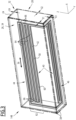
Figure 3 is a schematic, perspective view of the casing of an electrochemical cell of the battery shown inFigures 1 and2 , the casing being made transparent in order to show the first passive cooling system entirely, and -
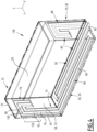
Figure 4 is a schematic, perspective view of the casing of an electrochemical cell of a battery according to a variant of the battery shown inFigures 1 to 3 , the casing being made transparent in order to show the first and a second passive cooling systems. - With reference to
Figures 1 to 3 , abattery 10 according to the invention will be described. - The
battery 10 is for example intended for an electrical or hybrid vehicle (not shown). - The
battery 10 is partially represented. For example, a general casing, potential crossbeams or other assembly elements, and electrical contacts, which may be present in thebattery 10, are not shown. - As shown in
Figure 1 , thebattery 10 comprises acooling plate 12 extending along a first direction X and a second direction Y perpendicular to the first direction X, and at least a set ofelectrochemical cells - The first direction X and the second direction Y are for example horizontal. The first direction X is for example the longitudinal (driving) direction of the vehicle.
- A third direction Z is also defined as perpendicular to the first direction X and to the second direction Y. The third direction Z is for example approximately vertical when the vehicle moves horizontally.
- In a preferred embodiment, the
battery 10 also comprises anactive cooling system 16 adapted for extracting heat from thecooling plate 12. - By "active" it is meant that the
cooling system 16 includes an energy consuming device (not shown), for example a pump, to displace a refrigerant fluid (not shown) of the cooling system. - The refrigerant fluid is adapted for circulating in the
cooling plate 12. - As a less preferred variant, the
battery 10 does not include an active cooling system to cool thecooling plate 12, but instead a passive one (not shown), such as cooling fins. - In the example, the
battery 10 also comprises twoend plates - The
cooling plate 12 is for example located at the bottom of thebattery 10. Thecooling plate 12 may be part of a general casing (not shown) of the battery, or may be separate from a general casing. - The
cooling plate 12 is in thermal contact, preferably in physical plane contact, with each of theelectrochemical cells - Advantageously, the
electrochemical cells electrochemical cell 14B will be described hereafter. - The
electrochemical cell 14B includes at least astack 22 of electrochemical elements, anelectrolyte 23, and acasing 24 surrounding thestack 22 and theelectrolyte 23 and comprising afirst part 26 and asecond part 28 opposite each other in the second direction Y (Figures 1 to 3 ), and athird part 30 and afourth part 32 opposite each other in the third direction Z. Theelectrochemical cell 14B comprises afirst plate 34 advantageously formed by thefirst part 26, and asecond plate 36 advantageously formed by thethird part 30, the first plate and the second plate being in thermal contact with thestack 22 and theelectrolyte 23 and adapted for receiving heat from thestack 22 or theelectrolyte 23. - The
electrochemical cell 14B advantageously comprises at least aphase change material 38 within thefirst plate 34 and thesecond plate 36. - The
electrochemical cell 14B comprises a firstpassive cooling system 40 comprising at least aloop heat pipe 42 having an evaporator 44 located in thefirst plate 34 and acondenser 46 located in thesecond plate 36. For example, thephase change material 38 fills the remaining space in thefirst plate 34 and the second plate 36 (around the first passive cooling system 40). - In the
casing 24, thefirst part 26 and thesecond part 28 are for example parallel to each other, and thethird part 30 and thefourth part 32 are for example parallel to each other. Thecasing 24 for example has a parallelepiped shape. - The
first plate 34 and thesecond plate 36 are adapted for receiving heat from thestack 22 and theelectrolyte 23, the coolingplate 12 being in thermal contact with thesecond plate 36 and adapted for receiving heat from the second plate. - The
first plate 34 and thesecond plate 36 are for example rectangular, and advantageously perpendicular to each other. - Advantageously, for any two successive
electrochemical cells 14A/14B or 14B/14C of the set, thefirst plate 34 of one of said electrochemical two cells is in thermal contact, and preferably in plane contact, with thesecond part 28 of the casing of the other one of said two electrochemical cells. In other words, theelectrochemical cells first plate 34 of theelectrochemical cells casing 24 of the neighboringelectrochemical cells - In a particular embodiment, the
first plate 34 and thesecond plate 36, considered as a whole, comprise aninternal wall 48 and anexternal wall 50 with respect to thestack 22 and theelectrolyte 23, the internal wall and the external wall defining, between themselves, aninner volume 52 extending in thefirst plate 34 and in thesecond plate 36. - For example, the
first plate 34 and thesecond plate 36, considered as a whole, comprise anotherwall 54 extending along apath 56 of afluid 58 of theloop heat pipe 42. - For example, the
first plate 34 has a thickness E1 along the second direction Y, and thesecond part 28 has a thickness E2 along the second direction Y, the thickness E1 being larger than the thickness E2. For example, thesecond plate 36 has a thickness E3 along the third direction Z, and thefourth part 32 has a thickness E4 along the third direction Z, the thickness E3 being larger than the thickness E4 of the fourth part. - The thicknesses E1 and E3 are for example comprised between 4mm and 8mm.
- The thicknesses E2 and E4 are for example comprised between 0.2mmmm and 3mm. The thicknesses E2 and E4 are for example about 0.6mm.
- As a less preferred variant (not shown), the
first plate 34 and thesecond plate 36 are not formed by thefirst part 26 and thethird part 30 of thecasing 24. Thefirst plate 34 and thesecond plate 36 may be distinct thecasing 24, and both in plane contact with thefirst part 26 and thethird part 30 respectively. Thefirst plate 34 and thesecond plate 36 altogether for example have an L-shape in view along the first direction X, and are advantageously integral with each other. In this case, thefirst plate 34 and thesecond plate 36 are in indirect thermal contact with thestack 22 and theelectrolyte 23 via thecasing 24. - The
other wall 54 for example has a U-shaped cross-section perpendicularly to thepath 56, and is fixed to theinternal wall 48, or as a variant (not shown) to theexternal wall 50, so as to form aduct 60 for the fluid 58. - The
phase change material 38 advantageously extends in theinner volume 52 in thefirst plate 34 and in thesecond plate 36. - The
phase change material 38 has a melting temperature comprised between 10°C and 120°C, preferably between 10°C and 40°C. - For example, the
phase change material 38 comprises n-octadecane, n-nonadecane, or n-eicosane. - As a variant (not shown), the first
passive cooling system 40 comprises at least a heat pipe or an oscillating heat pipe instead of, or in addition to, theloop heat pipe 42. - In other variants (not shown), the first
passive cooling system 40 may comprise several loop heat pipes and/or several oscillating heat pipes and/or several heat pipes. - Loop heat pipes, oscillating heat pipes and heat pipes are known in themselves and will not be described in detail. They include a phase change fluid circulating between an evaporator region, where the fluid receives heat, and a condenser region, where the fluid releases heat. Loop heat pipes, oscillating heat pipes and heat pipes are passive heat transporting systems, since the fluid circulation is obtained only via temperature differences and sometimes capillarity. In an oscillating heat pipe, the fluid comprises slugs of liquid and vapor in a continuous loop. Loop heat pipes and oscillating heat pipes may include fins in their evaporator and condenser regions.
- In this case, the
evaporator 44 is adapted for absorbing heat from thefirst plate 34, and thecondenser 46 is adapted for releasing heat to thesecond plate 36. - Advantageously, the
evaporator 44 extends in aportion 62 of thefirst plate 34, said portion being closer to thefourth part 32 than to thethird part 30 along the third direction Z. - In the example, the first
passive cooling system 40 comprises theduct 60 and the fluid 58. - The fluid 58 is adapted for circulating in the
duct 60 from theevaporator 44 to thecondenser 46, and from the condenser to the evaporator. - The
duct 60 for example comprises, in theevaporator 44 and thecondenser 46,successive sections 64 from a fluid circulation point of view, andU-shaped sections 66 in view along the second direction Y. - The
successive sections 64 for example extend along the first direction X and are connected to each other by theU-shaped sections 66. - The operation of the
battery 10 stems from its structure and will be briefly described in order to illustrate a process according to the invention. - During charging and discharging, heat is produced in the
electrochemical cells - In each of the
electrochemical cells first plate 34 and by the second plate 36 (whether the plates are formed by thecasing 24 or are separate elements in thermal contact with the casing). Thephase change material 38 advantageously present in theinner volume 52 in thefirst plate 34 and thesecond plate 36 makes sure that temperature does not go too high in each electrochemical cell, by absorbing some of the heat due to a phase change. The presence of the firstpassive cooling system 40 ensures that the PCM does not change its phase quickly by carrying out that excessive heat towards the coolingplate 12. - Heat is also absorbed by the evaporator 44 from the
first plate 34. Heat is released by thecondenser 44 to thesecond plate 36, and heat is received by the coolingplate 12 from thesecond plate 36. - Heat is then evacuated from the cooling
plate 12 for example by thecooling system 16. - Thanks to the above features, the risk of hot spots or too strong gradients appearing in the
battery 10 is reduced and the battery is very compact. - The
phase change material 38 advantageously acts as a passive cooling system in order to prevent the temperature from raising when heat is released in theelectrochemical cells passive cooling system 40, thanks to theloop heat pipe 42, the oscillating heat pipe or the heat pipe, is able to convey heat from thefirst plate 34 to thesecond plate 36, the heat being then absorbed by the coolingplate 12. Thephase change material 38 and the firstpassive cooling system 40 manage to keep the temperature more homogenous than in prior art batteries, in particular in the top part of theelectrochemical cells - The homogenous temperature distribution helps reducing degradation in the
battery 10, for example by reducing lithium plating. It increases the life of thebattery 10. - The
phase change material 38 and the firstpassive cooling system 40, being both passive, are unlikely to fail. - The embodiment in which the
first plate 34 and thesecond plate 36 are formed by thecasing 24 is particularly interesting in terms of compactness. - Thanks to the optional feature of having the
electrochemical cells first plate 34 of one electrochemical cell can absorb heat from thesecond part 28 of thecasing 24 of a neighboring electrochemical cell. - Thanks to the optional feature of having the evaporator 44 in the
portion 62 of thefirst plate 34, closer to thefourth part 32 than to thethird part 30 along the third direction Z, the firstpassive cooling system 40 is able to extract excess heat where it more likely to appear, i.e. away from the coolingplate 12. - With reference to
Figure 4 , a variant of thebattery 10 will now be described. That variant is analogous to the battery represented inFigure 1 to 3 . Similar elements will not be described again. Only the differences will be described hereafter. - In that variant, the
casing 24 surrounding thestack 22 and theelectrolyte 23 comprises a first part 68 and a second part 70 that are opposite each other in the first direction X, and not in the second direction Y. - In the variant, the
electrochemical cell 14B includes a first plate 72 either formed by the first part 68 or in plane contact with the first part, the first plate 72 being in thermal contact with thestack 22 and adapted for receiving heat from the stack. Theelectrochemical cell 14B comprises a firstpassive cooling system 74 comprising at least aheat pipe 76, the first passive cooling system comprising anevaporator 78 located in the first plate 72 and adapted for absorbing heat from the first plate, and acondenser 80 located in thesecond plate 36 and adapted for releasing heat to the second plate. - Advantageously, the
electrochemical cell 14B further includes a third plate 82 either formed by the second part 70 or in plane contact with the second part, the third plate being in thermal contact with thestack 22 and theelectrolyte 23 adapted for receiving heat from the stack and the electrolyte. - The
electrochemical cell 14B further comprises a secondpassive cooling system 84 comprising at least aheat pipe 86, the second passive cooling system comprising anevaporator 88 located in the third plate 82 and adapted for absorbing heat from the third plate, and acondenser 90 located in thesecond plate 36 and adapted for releasing heat to the second plate. - The
electrochemical cell 14B may comprise a phase change material (not represented) in the first plate 72 and/or in the third plate 82. - Advantageously, the first
passive cooling system 74 and the secondpassive cooling system 84 are structurally analogous to each other. Only the firstpassive cooling system 74 will be described. - Heat pipes are known in themselves and will not be described in detail. They include a phase change fluid circulating between an evaporator region, where the fluid receives heat, and a condenser region, where the fluid releases heat. The fluid circulation is obtained only via temperature differences and sometimes capillarity.
- The
heat pipe 76 of the firstpassive cooling system 74 comprises aduct 92 and a fluid 94 adapted for circulating in the duct. - The
duct 92 has asection 96 in thecondenser 80, said section extending in the first direction X, and aU-shaped section 98 in view along the first direction X. - The
U-shaped section 98 is located the evaporator 78, the "U" of the U-shaped section having a base 100 pointing away from thethird part 30 in the third direction Z. - Advantageously, the
evaporator 78 extends in aportion 102 of the first plate 72, said portion being closer to thefourth part 32 than to the third part along the third direction Z. - The first
passive cooling system 74 operates in the same manner as the firstpassive cooling system 40 shown infigure 3 , by receiving heat from the first plate 72 and releasing heat to thesecond plate 36.
Claims (15)
- A battery (10) for an electrical or hybrid vehicle, the battery (10) comprising:- a cooling plate (12) extending along a first direction (X) and a second direction (Y) perpendicular to the first direction (X), and- at least a set of electrochemical cells (14A, 14B, 14C) extending successively along the second direction (Y),each of the electrochemical cells (14A, 14B, 14C) including:- at least a stack (22) of electrochemical elements and an electrolyte (23),- a casing (24) surrounding the stack (22) and the electrolyte (23), and comprising a first part (26; 68) and a second part (28; 70) opposite each other in one of the second direction (Y) and the first direction (X), and a third part (30) and a fourth part (32) opposite each other in a third direction (Z) perpendicular to the first direction (X) and to the second direction (Y),- a first plate (34; 72) either formed by the first part (26; 68), or in plane contact with the first part (26; 68), the first plate (34; 72) being in thermal contact with the stack (22) and the electrolyte (23) and adapted for receiving heat from the stack (22) and the electrolyte (23),- a second plate (36) either formed by the third part (30), or in plane contact with the third part (30), the second plate (36) being in thermal contact with the stack (22) and the electrolyte (23) and adapted for receiving heat from the stack (22) and the electrolyte (23), the cooling plate (12) being in thermal contact with the second plate (36) and adapted for receiving heat from the second plate (36), and- a first passive cooling system (40; 74) comprising at least a loop heat pipe (42), an oscillating heat pipe, or a heat pipe, the first passive cooling system (40; 74) comprising an evaporator (44; 78) located in the first plate (34, 72) and adapted for absorbing heat from the first plate (34, 72), and a condenser (46; 80) located in the second plate (36) and adapted for releasing heat to the second plate (36).
- The battery (10) according to claim 1, further comprising an active cooling system (16) adapted for extracting heat from the cooling plate (12).
- The battery (10) according to claim 1 or 2, wherein the first plate (34; 72) and the second plate (36) are both distinct from the casing (24), and altogether have an L-shape in view along the other of the second direction (Y) and the first direction (X).
- The battery (10) according to any one of claims 1 to 3, wherein each of the electrochemical cells (14A, 14B, 14C) further includes at least a phase change material (38) within the first plate (34; 72) and the second plate (36), wherein the phase change material (38) has a melting temperature comprised between 10°C and 120°C.
- The battery (10) according to claim 4, wherein the first plate (34; 72) and the second plate (36), considered as a whole, comprise an internal wall (48) and an external wall (50) with respect to the stack (22) and the electrolyte (23), the internal wall (48) and the external wall (50) defining, between themselves, an inner volume (52) extending in the first plate (34; 72) and in the second plate (36), the phase change material (38) extending in the inner volume (52) in the first plate (34; 72) and in the second plate (36).
- The battery (10) according to claim 5, wherein the first plate (34; 72) and the second plate (36), considered as a whole, comprise another wall (54) extending along a path (56) of a fluid (58) of the loop heat pipe (42), the oscillating heat pipe or the heat pipe, the other wall (54) having a U-shaped cross-section perpendicularly to the path (56), and being fixed to the internal wall (48) or the external wall (50) so as to form a duct (60) for the fluid (58).
- The battery (10) according to any one of claim 1 to 6, wherein the first passive cooling system (40; 74) comprises a duct (60) and a fluid (58) adapted for circulating in the duct (60) from the evaporator (44; 78) to the condenser (46; 80), and from the condenser (46; 80) to the evaporator (44; 78), the duct (60) comprising, in the evaporator (44; 78) and the condenser (46; 80), successive sections (64) from a fluid (58) circulation point of view, and U-shaped sections (66) in view along said one of the second direction (Y) and the first direction (X), the successive sections (64) extending along said other one of the second direction (Y) and the first direction (X) and being connected to each other by the U-shaped sections (66).
- The battery (10) according to any one of claim 1 to 7, wherein the evaporator (44; 78) extends in a portion (62) of the first plate (34; 72), said portion (62) being closer to the fourth part (32) than to the third part (30) along the third direction (Z).
- The battery (10) according to any one of claim 1 to 8, wherein:- the first plate (34) has a thickness (E1) along said one of the second direction (Y) and the first direction (X), and the second part (28) has a thickness (E2) along said one of the second direction (Y) and the first direction (X), the thickness (E1) of the first plate (34) being larger than the thickness (E2) of the second part (28), and- the second plate (36) has a thickness (E3) along the third direction (Z), and the fourth part (32) has a thickness (E4) along the third direction (Z), the thickness (E3) of the second plate (36) being larger than the thickness (E4) of the fourth part (32).
- The battery (10) according to any one of claims 1 to 9, wherein:- the first part (26) and the second part (28) are opposite each other in the second direction (Y), and- for any two successive electrochemical cells of the electrochemical cells (14A, 14B, 14C) of said set, the first plate (34) of one of said two successive electrochemical cells is in thermal contact with the second part (28) of the casing (24) of the other one of said two successive electrochemical cells.
- The battery (10) according to any one of claim 1 to 9, wherein the first part (68) and the second part (70) are opposite each other in the first direction (X), the first passive cooling system (74) comprising a heat pipe (76).
- The battery (10) according to claim 11, wherein each of the electrochemical cells (14A, 14B, 14C) further comprises:- a third plate (82) either formed by the second part (70) or in plane contact with the second part (70), the third plate (82) being in thermal contact with the stack (22) and the electrolyte (23), and adapted for receiving heat from the stack (22) or the electrolyte (23), and- a second passive cooling system (84) comprising a heat pipe (86), the second passive cooling system (84) comprising an evaporator (88) located in the third plate (82) and adapted for absorbing heat from the third plate (82), and a condenser (90) located in the second plate (36) and adapted for releasing heat to the second plate (36).
- The battery (10) according to claim 11 or 12, wherein the heat pipe (76) of the first passive cooling system (74) comprises a duct (92) and a fluid (94) adapted for circulating in the duct (92), the duct (92) having a section (96) in the condenser (80) of the first passive cooling system (74), said section (96) extending in the first direction (X), and a U-shaped section (98) in view along the first direction (X), the U-shaped section (98) being located in the evaporator (78) of the first passive cooling system (74), the "U" of the U-shaped section (98) having a base (100) pointing away from the third part (30) in the third direction (Z).
- The battery (10) according to any one of claim 11 to 13, wherein the evaporator (78) of the first passive cooling system (74) extends in a portion (102) of the first plate (72), said portion (102) being closer to the fourth part (32) than to the third part (30) along the third direction (Z).
- A process for cooling a battery (10), comprising:- providing a battery (10) according to any one of claims 1 to 14,- a step of receiving heat by the first plate (34; 72) and the second plate (36) from the stack (22) and the electrolyte (23),- a step of absorbing heat by the evaporator (44; 78) of the first passive cooling system (40; 74) from the first plate (34; 72),- a step of releasing heat by the condenser (46; 80) of the first passive cooling system (40; 74) to the second plate (36), and- a step of receiving heat by the cooling plate (12) from the second plate (36).
Priority Applications (1)
| Application Number | Priority Date | Filing Date | Title |
|---|---|---|---|
| EP22306539.2A EP4354593A1 (en) | 2022-10-12 | 2022-10-12 | Battery for an electrical or hybrid vehicle, comprising loop or oscillating heat pipes, or heat pipes |
Applications Claiming Priority (1)
| Application Number | Priority Date | Filing Date | Title |
|---|---|---|---|
| EP22306539.2A EP4354593A1 (en) | 2022-10-12 | 2022-10-12 | Battery for an electrical or hybrid vehicle, comprising loop or oscillating heat pipes, or heat pipes |
Publications (1)
| Publication Number | Publication Date |
|---|---|
| EP4354593A1 true EP4354593A1 (en) | 2024-04-17 |
Family
ID=83903375
Family Applications (1)
| Application Number | Title | Priority Date | Filing Date |
|---|---|---|---|
| EP22306539.2A Pending EP4354593A1 (en) | 2022-10-12 | 2022-10-12 | Battery for an electrical or hybrid vehicle, comprising loop or oscillating heat pipes, or heat pipes |
Country Status (1)
| Country | Link |
|---|---|
| EP (1) | EP4354593A1 (en) |
Citations (4)
| Publication number | Priority date | Publication date | Assignee | Title |
|---|---|---|---|---|
| FR3015780A3 (en) * | 2013-12-23 | 2015-06-26 | Renault Sa | SYSTEM FOR HOLDING A BATTERY TEMPERATURE. |
| CN106972219A (en) * | 2017-03-22 | 2017-07-21 | 江苏中关村科技产业园节能环保研究有限公司 | A kind of plate-type battery coldplate of application hot pipe technique |
| CN112952237A (en) * | 2021-02-07 | 2021-06-11 | 暨南大学 | Battery heat management device, battery module and battery heat management method |
| CN113675499A (en) * | 2021-07-31 | 2021-11-19 | 华南理工大学 | Vehicle battery fast charging thermal management system and temperature control method based on L-shaped pulsating heat pipe |
-
2022
- 2022-10-12 EP EP22306539.2A patent/EP4354593A1/en active Pending
Patent Citations (4)
| Publication number | Priority date | Publication date | Assignee | Title |
|---|---|---|---|---|
| FR3015780A3 (en) * | 2013-12-23 | 2015-06-26 | Renault Sa | SYSTEM FOR HOLDING A BATTERY TEMPERATURE. |
| CN106972219A (en) * | 2017-03-22 | 2017-07-21 | 江苏中关村科技产业园节能环保研究有限公司 | A kind of plate-type battery coldplate of application hot pipe technique |
| CN112952237A (en) * | 2021-02-07 | 2021-06-11 | 暨南大学 | Battery heat management device, battery module and battery heat management method |
| CN113675499A (en) * | 2021-07-31 | 2021-11-19 | 华南理工大学 | Vehicle battery fast charging thermal management system and temperature control method based on L-shaped pulsating heat pipe |
Non-Patent Citations (1)
| Title |
|---|
| PATEL JAY R ET AL: "Recent developments in the passive and hybrid thermal management techniques of lithium-ion batteries", JOURNAL OF POWER SOURCES, ELSEVIER, AMSTERDAM, NL, vol. 480, 3 September 2020 (2020-09-03), XP086351036, ISSN: 0378-7753, [retrieved on 20200903], DOI: 10.1016/J.JPOWSOUR.2020.228820 * |
Similar Documents
| Publication | Publication Date | Title |
|---|---|---|
| US10784015B2 (en) | Bus bar with novel structure | |
| US9023503B2 (en) | Battery module with cooling structure of high efficiency | |
| CN105452025B (en) | Temperature controller for battery | |
| US9865904B2 (en) | Battery cell of improved cooling efficiency | |
| US9452686B2 (en) | Cooling member of novel structure and battery module employed with the same | |
| US10283822B2 (en) | Battery module assembly | |
| US20190148681A1 (en) | Battery module having heat pipe and battery pack including the same | |
| US10804578B2 (en) | Battery module, battery pack and vehicle having same | |
| KR102210218B1 (en) | Battery system, base plate for a battery system and electric vehicle | |
| US20210151821A1 (en) | Battery Module | |
| US20130149576A1 (en) | Battery module with compact structure and excellent heat radiation characteristics and middle or large-sized battery pack employed with the same | |
| US20150064535A1 (en) | Battery module having indirect air-cooling structure | |
| US10957955B2 (en) | Battery module and battery pack including the same | |
| EP4428990A1 (en) | Battery module and battery pack comprising same | |
| KR102683482B1 (en) | Battery Pack | |
| EP4354593A1 (en) | Battery for an electrical or hybrid vehicle, comprising loop or oscillating heat pipes, or heat pipes | |
| CN219759856U (en) | Battery case and lithium battery module | |
| JP7749431B2 (en) | Battery System | |
| KR102941955B1 (en) | Battery module cooling apparatus | |
| US20250125447A1 (en) | Heat pipe and battery pack including the same | |
| KR102832587B1 (en) | Long-Term Large Capacity Battery Capacitor Module by Contact Cooling Method | |
| KR102926718B1 (en) | Coolable battery module | |
| CN121548893A (en) | Systems for cooling objects | |
| EP4459745A1 (en) | Battery module and battery pack including the same | |
| EP4471941B1 (en) | Double-sided cooling-type battery module and heat sink included therein |
Legal Events
| Date | Code | Title | Description |
|---|---|---|---|
| PUAI | Public reference made under article 153(3) epc to a published international application that has entered the european phase |
Free format text: ORIGINAL CODE: 0009012 |
|
| STAA | Information on the status of an ep patent application or granted ep patent |
Free format text: STATUS: THE APPLICATION HAS BEEN PUBLISHED |
|
| AK | Designated contracting states |
Kind code of ref document: A1 Designated state(s): AL AT BE BG CH CY CZ DE DK EE ES FI FR GB GR HR HU IE IS IT LI LT LU LV MC ME MK MT NL NO PL PT RO RS SE SI SK SM TR |
|
| P01 | Opt-out of the competence of the unified patent court (upc) registered |
Effective date: 20240420 |
|
| STAA | Information on the status of an ep patent application or granted ep patent |
Free format text: STATUS: REQUEST FOR EXAMINATION WAS MADE |
|
| 17P | Request for examination filed |
Effective date: 20240930 |
|
| RBV | Designated contracting states (corrected) |
Designated state(s): AL AT BE BG CH CY CZ DE DK EE ES FI FR GB GR HR HU IE IS IT LI LT LU LV MC ME MK MT NL NO PL PT RO RS SE SI SK SM TR |
|
| RAP3 | Party data changed (applicant data changed or rights of an application transferred) |
Owner name: AUTOMOTIVE CELLS COMPANY SE |
|
| RAP3 | Party data changed (applicant data changed or rights of an application transferred) |
Owner name: AUTOMOTIVE CELLS COMPANY SE |