EP4354543A1 - Electrochemical device and electronic device - Google Patents
Electrochemical device and electronic device Download PDFInfo
- Publication number
- EP4354543A1 EP4354543A1 EP23202923.1A EP23202923A EP4354543A1 EP 4354543 A1 EP4354543 A1 EP 4354543A1 EP 23202923 A EP23202923 A EP 23202923A EP 4354543 A1 EP4354543 A1 EP 4354543A1
- Authority
- EP
- European Patent Office
- Prior art keywords
- additive
- electrochemical device
- electrolytic solution
- active material
- substituted
- Prior art date
- Legal status (The legal status is an assumption and is not a legal conclusion. Google has not performed a legal analysis and makes no representation as to the accuracy of the status listed.)
- Pending
Links
- 239000000654 additive Substances 0.000 claims abstract description 139
- 230000000996 additive effect Effects 0.000 claims abstract description 138
- OAICVXFJPJFONN-UHFFFAOYSA-N Phosphorus Chemical compound [P] OAICVXFJPJFONN-UHFFFAOYSA-N 0.000 claims abstract description 59
- 229910052698 phosphorus Inorganic materials 0.000 claims abstract description 59
- 239000011574 phosphorus Substances 0.000 claims abstract description 59
- 239000008151 electrolyte solution Substances 0.000 claims abstract description 58
- 239000007774 positive electrode material Substances 0.000 claims abstract description 45
- SBLRHMKNNHXPHG-UHFFFAOYSA-N 4-fluoro-1,3-dioxolan-2-one Chemical compound FC1COC(=O)O1 SBLRHMKNNHXPHG-UHFFFAOYSA-N 0.000 claims abstract description 30
- VAYTZRYEBVHVLE-UHFFFAOYSA-N 1,3-dioxol-2-one Chemical compound O=C1OC=CO1 VAYTZRYEBVHVLE-UHFFFAOYSA-N 0.000 claims abstract description 12
- 229910052782 aluminium Inorganic materials 0.000 claims abstract description 9
- 150000001875 compounds Chemical class 0.000 claims description 33
- OKTJSMMVPCPJKN-UHFFFAOYSA-N Carbon Chemical compound [C] OKTJSMMVPCPJKN-UHFFFAOYSA-N 0.000 claims description 23
- 239000007773 negative electrode material Substances 0.000 claims description 22
- BTGRAWJCKBQKAO-UHFFFAOYSA-N adiponitrile Chemical compound N#CCCCCC#N BTGRAWJCKBQKAO-UHFFFAOYSA-N 0.000 claims description 18
- 229910002804 graphite Inorganic materials 0.000 claims description 13
- 239000010439 graphite Substances 0.000 claims description 13
- IAHFWCOBPZCAEA-UHFFFAOYSA-N succinonitrile Chemical compound N#CCCC#N IAHFWCOBPZCAEA-UHFFFAOYSA-N 0.000 claims description 13
- 239000002210 silicon-based material Substances 0.000 claims description 11
- BTNXBLUGMAMSSH-UHFFFAOYSA-N octanedinitrile Chemical compound N#CCCCCCCC#N BTNXBLUGMAMSSH-UHFFFAOYSA-N 0.000 claims description 9
- 229920005554 polynitrile Polymers 0.000 claims description 9
- 125000000882 C2-C6 alkenyl group Chemical group 0.000 claims description 8
- LLEVMYXEJUDBTA-UHFFFAOYSA-N heptanedinitrile Chemical compound N#CCCCCCC#N LLEVMYXEJUDBTA-UHFFFAOYSA-N 0.000 claims description 8
- 125000004051 hexyl group Chemical group [H]C([H])([H])C([H])([H])C([H])([H])C([H])([H])C([H])([H])C([H])([H])* 0.000 claims description 8
- 125000003545 alkoxy group Chemical group 0.000 claims description 7
- LNLFLMCWDHZINJ-UHFFFAOYSA-N hexane-1,3,6-tricarbonitrile Chemical compound N#CCCCC(C#N)CCC#N LNLFLMCWDHZINJ-UHFFFAOYSA-N 0.000 claims description 7
- ALGVJKNIAOBBBJ-UHFFFAOYSA-N 3-[2,3-bis(2-cyanoethoxy)propoxy]propanenitrile Chemical compound N#CCCOCC(OCCC#N)COCCC#N ALGVJKNIAOBBBJ-UHFFFAOYSA-N 0.000 claims description 6
- XUIMIQQOPSSXEZ-UHFFFAOYSA-N Silicon Chemical group [Si] XUIMIQQOPSSXEZ-UHFFFAOYSA-N 0.000 claims description 6
- 125000000304 alkynyl group Chemical group 0.000 claims description 6
- 229910021383 artificial graphite Inorganic materials 0.000 claims description 6
- 125000004093 cyano group Chemical group *C#N 0.000 claims description 6
- 229910052736 halogen Inorganic materials 0.000 claims description 6
- 239000002153 silicon-carbon composite material Substances 0.000 claims description 6
- 239000003575 carbonaceous material Substances 0.000 claims description 5
- 150000002367 halogens Chemical class 0.000 claims description 5
- SXLDJBWDCDALLM-UHFFFAOYSA-N hexane-1,2,6-tricarbonitrile Chemical compound N#CCCCCC(C#N)CC#N SXLDJBWDCDALLM-UHFFFAOYSA-N 0.000 claims description 5
- MNAMONWYCZEPTE-UHFFFAOYSA-N propane-1,2,3-tricarbonitrile Chemical compound N#CCC(C#N)CC#N MNAMONWYCZEPTE-UHFFFAOYSA-N 0.000 claims description 5
- ZTOMUSMDRMJOTH-UHFFFAOYSA-N glutaronitrile Chemical compound N#CCCCC#N ZTOMUSMDRMJOTH-UHFFFAOYSA-N 0.000 claims description 4
- RXIMZKYZCDNHPG-UHFFFAOYSA-N pentane-1,3,5-tricarbonitrile Chemical compound N#CCCC(C#N)CCC#N RXIMZKYZCDNHPG-UHFFFAOYSA-N 0.000 claims description 4
- 125000001424 substituent group Chemical group 0.000 claims description 4
- ZVQXQPNJHRNGID-UHFFFAOYSA-N tetramethylsuccinonitrile Chemical compound N#CC(C)(C)C(C)(C)C#N ZVQXQPNJHRNGID-UHFFFAOYSA-N 0.000 claims description 4
- VTHRQKSLPFJQHN-UHFFFAOYSA-N 3-[2-(2-cyanoethoxy)ethoxy]propanenitrile Chemical compound N#CCCOCCOCCC#N VTHRQKSLPFJQHN-UHFFFAOYSA-N 0.000 claims description 3
- OBNDGIHQAIXEAO-UHFFFAOYSA-N [O].[Si] Chemical compound [O].[Si] OBNDGIHQAIXEAO-UHFFFAOYSA-N 0.000 claims description 3
- 125000003172 aldehyde group Chemical group 0.000 claims description 3
- 239000002131 composite material Substances 0.000 claims description 3
- 229910021382 natural graphite Inorganic materials 0.000 claims description 3
- 229910052710 silicon Inorganic materials 0.000 claims description 3
- 239000010703 silicon Substances 0.000 claims description 3
- 125000000542 sulfonic acid group Chemical group 0.000 claims description 3
- PYMZYVXDCJXPAM-UHFFFAOYSA-N ethane-1,2-diol;propanenitrile Chemical compound CCC#N.CCC#N.OCCO PYMZYVXDCJXPAM-UHFFFAOYSA-N 0.000 claims 1
- 125000005843 halogen group Chemical group 0.000 claims 1
- 230000035939 shock Effects 0.000 abstract description 33
- 230000016507 interphase Effects 0.000 description 33
- 230000000052 comparative effect Effects 0.000 description 27
- HBBGRARXTFLTSG-UHFFFAOYSA-N Lithium ion Chemical compound [Li+] HBBGRARXTFLTSG-UHFFFAOYSA-N 0.000 description 21
- 229910001416 lithium ion Inorganic materials 0.000 description 21
- 238000012360 testing method Methods 0.000 description 14
- -1 carbonate compound Chemical class 0.000 description 11
- OPFJDXRVMFKJJO-ZHHKINOHSA-N N-{[3-(2-benzamido-4-methyl-1,3-thiazol-5-yl)-pyrazol-5-yl]carbonyl}-G-dR-G-dD-dD-dD-NH2 Chemical compound S1C(C=2NN=C(C=2)C(=O)NCC(=O)N[C@H](CCCN=C(N)N)C(=O)NCC(=O)N[C@H](CC(O)=O)C(=O)N[C@H](CC(O)=O)C(=O)N[C@H](CC(O)=O)C(N)=O)=C(C)N=C1NC(=O)C1=CC=CC=C1 OPFJDXRVMFKJJO-ZHHKINOHSA-N 0.000 description 9
- 239000011230 binding agent Substances 0.000 description 9
- 229940126086 compound 21 Drugs 0.000 description 9
- 239000006258 conductive agent Substances 0.000 description 7
- 229910003002 lithium salt Inorganic materials 0.000 description 7
- 159000000002 lithium salts Chemical class 0.000 description 7
- 239000000126 substance Substances 0.000 description 7
- 230000002378 acidificating effect Effects 0.000 description 6
- 229910052799 carbon Inorganic materials 0.000 description 6
- 238000000354 decomposition reaction Methods 0.000 description 6
- 239000011888 foil Substances 0.000 description 6
- 239000002002 slurry Substances 0.000 description 6
- UNILWMWFPHPYOR-KXEYIPSPSA-M 1-[6-[2-[3-[3-[3-[2-[2-[3-[[2-[2-[[(2r)-1-[[2-[[(2r)-1-[3-[2-[2-[3-[[2-(2-amino-2-oxoethoxy)acetyl]amino]propoxy]ethoxy]ethoxy]propylamino]-3-hydroxy-1-oxopropan-2-yl]amino]-2-oxoethyl]amino]-3-[(2r)-2,3-di(hexadecanoyloxy)propyl]sulfanyl-1-oxopropan-2-yl Chemical compound O=C1C(SCCC(=O)NCCCOCCOCCOCCCNC(=O)COCC(=O)N[C@@H](CSC[C@@H](COC(=O)CCCCCCCCCCCCCCC)OC(=O)CCCCCCCCCCCCCCC)C(=O)NCC(=O)N[C@H](CO)C(=O)NCCCOCCOCCOCCCNC(=O)COCC(N)=O)CC(=O)N1CCNC(=O)CCCCCN\1C2=CC=C(S([O-])(=O)=O)C=C2CC/1=C/C=C/C=C/C1=[N+](CC)C2=CC=C(S([O-])(=O)=O)C=C2C1 UNILWMWFPHPYOR-KXEYIPSPSA-M 0.000 description 5
- XAGFODPZIPBFFR-UHFFFAOYSA-N aluminium Chemical compound [Al] XAGFODPZIPBFFR-UHFFFAOYSA-N 0.000 description 5
- 229920002125 Sokalan® Polymers 0.000 description 4
- 239000000203 mixture Substances 0.000 description 4
- 239000004584 polyacrylic acid Substances 0.000 description 4
- 238000007086 side reaction Methods 0.000 description 4
- SZUVGFMDDVSKSI-WIFOCOSTSA-N (1s,2s,3s,5r)-1-(carboxymethyl)-3,5-bis[(4-phenoxyphenyl)methyl-propylcarbamoyl]cyclopentane-1,2-dicarboxylic acid Chemical compound O=C([C@@H]1[C@@H]([C@](CC(O)=O)([C@H](C(=O)N(CCC)CC=2C=CC(OC=3C=CC=CC=3)=CC=2)C1)C(O)=O)C(O)=O)N(CCC)CC(C=C1)=CC=C1OC1=CC=CC=C1 SZUVGFMDDVSKSI-WIFOCOSTSA-N 0.000 description 3
- QFLWZFQWSBQYPS-AWRAUJHKSA-N (3S)-3-[[(2S)-2-[[(2S)-2-[5-[(3aS,6aR)-2-oxo-1,3,3a,4,6,6a-hexahydrothieno[3,4-d]imidazol-4-yl]pentanoylamino]-3-methylbutanoyl]amino]-3-(4-hydroxyphenyl)propanoyl]amino]-4-[1-bis(4-chlorophenoxy)phosphorylbutylamino]-4-oxobutanoic acid Chemical compound CCCC(NC(=O)[C@H](CC(O)=O)NC(=O)[C@H](Cc1ccc(O)cc1)NC(=O)[C@@H](NC(=O)CCCCC1SC[C@@H]2NC(=O)N[C@H]12)C(C)C)P(=O)(Oc1ccc(Cl)cc1)Oc1ccc(Cl)cc1 QFLWZFQWSBQYPS-AWRAUJHKSA-N 0.000 description 3
- RYGMFSIKBFXOCR-UHFFFAOYSA-N Copper Chemical compound [Cu] RYGMFSIKBFXOCR-UHFFFAOYSA-N 0.000 description 3
- OIFBSDVPJOWBCH-UHFFFAOYSA-N Diethyl carbonate Chemical compound CCOC(=O)OCC OIFBSDVPJOWBCH-UHFFFAOYSA-N 0.000 description 3
- KMTRUDSVKNLOMY-UHFFFAOYSA-N Ethylene carbonate Chemical compound O=C1OCCO1 KMTRUDSVKNLOMY-UHFFFAOYSA-N 0.000 description 3
- 239000004743 Polypropylene Substances 0.000 description 3
- 239000001768 carboxy methyl cellulose Substances 0.000 description 3
- 229940126543 compound 14 Drugs 0.000 description 3
- 239000011889 copper foil Substances 0.000 description 3
- 239000003792 electrolyte Substances 0.000 description 3
- 238000001465 metallisation Methods 0.000 description 3
- 238000000034 method Methods 0.000 description 3
- 229920001155 polypropylene Polymers 0.000 description 3
- 229920002981 polyvinylidene fluoride Polymers 0.000 description 3
- 229920003048 styrene butadiene rubber Polymers 0.000 description 3
- AOSZTAHDEDLTLQ-AZKQZHLXSA-N (1S,2S,4R,8S,9S,11S,12R,13S,19S)-6-[(3-chlorophenyl)methyl]-12,19-difluoro-11-hydroxy-8-(2-hydroxyacetyl)-9,13-dimethyl-6-azapentacyclo[10.8.0.02,9.04,8.013,18]icosa-14,17-dien-16-one Chemical compound C([C@@H]1C[C@H]2[C@H]3[C@]([C@]4(C=CC(=O)C=C4[C@@H](F)C3)C)(F)[C@@H](O)C[C@@]2([C@@]1(C1)C(=O)CO)C)N1CC1=CC=CC(Cl)=C1 AOSZTAHDEDLTLQ-AZKQZHLXSA-N 0.000 description 2
- ZZXUZKXVROWEIF-UHFFFAOYSA-N 1,2-butylene carbonate Chemical compound CCC1COC(=O)O1 ZZXUZKXVROWEIF-UHFFFAOYSA-N 0.000 description 2
- BJWMSGRKJIOCNR-UHFFFAOYSA-N 4-ethenyl-1,3-dioxolan-2-one Chemical compound C=CC1COC(=O)O1 BJWMSGRKJIOCNR-UHFFFAOYSA-N 0.000 description 2
- 229920000049 Carbon (fiber) Polymers 0.000 description 2
- 229920002134 Carboxymethyl cellulose Polymers 0.000 description 2
- 229940126657 Compound 17 Drugs 0.000 description 2
- 229910001290 LiPF6 Inorganic materials 0.000 description 2
- SECXISVLQFMRJM-UHFFFAOYSA-N N-Methylpyrrolidone Chemical compound CN1CCCC1=O SECXISVLQFMRJM-UHFFFAOYSA-N 0.000 description 2
- 239000004698 Polyethylene Substances 0.000 description 2
- DPXJVFZANSGRMM-UHFFFAOYSA-N acetic acid;2,3,4,5,6-pentahydroxyhexanal;sodium Chemical compound [Na].CC(O)=O.OCC(O)C(O)C(O)C(O)C=O DPXJVFZANSGRMM-UHFFFAOYSA-N 0.000 description 2
- 239000006230 acetylene black Substances 0.000 description 2
- 239000004917 carbon fiber Substances 0.000 description 2
- 229910021393 carbon nanotube Inorganic materials 0.000 description 2
- 239000002041 carbon nanotube Substances 0.000 description 2
- 238000005056 compaction Methods 0.000 description 2
- 229940126214 compound 3 Drugs 0.000 description 2
- 230000007797 corrosion Effects 0.000 description 2
- 238000005260 corrosion Methods 0.000 description 2
- 238000005520 cutting process Methods 0.000 description 2
- VUPKGFBOKBGHFZ-UHFFFAOYSA-N dipropyl carbonate Chemical compound CCCOC(=O)OCCC VUPKGFBOKBGHFZ-UHFFFAOYSA-N 0.000 description 2
- 229910021389 graphene Inorganic materials 0.000 description 2
- 150000002484 inorganic compounds Chemical class 0.000 description 2
- 229910010272 inorganic material Inorganic materials 0.000 description 2
- 239000003273 ketjen black Substances 0.000 description 2
- 238000006138 lithiation reaction Methods 0.000 description 2
- 229910000625 lithium cobalt oxide Inorganic materials 0.000 description 2
- QSZMZKBZAYQGRS-UHFFFAOYSA-N lithium;bis(trifluoromethylsulfonyl)azanide Chemical compound [Li+].FC(F)(F)S(=O)(=O)[N-]S(=O)(=O)C(F)(F)F QSZMZKBZAYQGRS-UHFFFAOYSA-N 0.000 description 2
- BFZPBUKRYWOWDV-UHFFFAOYSA-N lithium;oxido(oxo)cobalt Chemical compound [Li+].[O-][Co]=O BFZPBUKRYWOWDV-UHFFFAOYSA-N 0.000 description 2
- 229910021645 metal ion Inorganic materials 0.000 description 2
- VNWKTOKETHGBQD-UHFFFAOYSA-N methane Chemical compound C VNWKTOKETHGBQD-UHFFFAOYSA-N 0.000 description 2
- KKQAVHGECIBFRQ-UHFFFAOYSA-N methyl propyl carbonate Chemical compound CCCOC(=O)OC KKQAVHGECIBFRQ-UHFFFAOYSA-N 0.000 description 2
- 229920000058 polyacrylate Polymers 0.000 description 2
- 229920000573 polyethylene Polymers 0.000 description 2
- 229920000036 polyvinylpyrrolidone Polymers 0.000 description 2
- 239000001267 polyvinylpyrrolidone Substances 0.000 description 2
- 235000013855 polyvinylpyrrolidone Nutrition 0.000 description 2
- RUOJZAUFBMNUDX-UHFFFAOYSA-N propylene carbonate Chemical compound CC1COC(=O)O1 RUOJZAUFBMNUDX-UHFFFAOYSA-N 0.000 description 2
- 235000019812 sodium carboxymethyl cellulose Nutrition 0.000 description 2
- 229920001027 sodium carboxymethylcellulose Polymers 0.000 description 2
- 159000000000 sodium salts Chemical class 0.000 description 2
- 239000007784 solid electrolyte Substances 0.000 description 2
- 239000002904 solvent Substances 0.000 description 2
- 238000003756 stirring Methods 0.000 description 2
- 230000002195 synergetic effect Effects 0.000 description 2
- WWTBZEKOSBFBEM-SPWPXUSOSA-N (2s)-2-[[2-benzyl-3-[hydroxy-[(1r)-2-phenyl-1-(phenylmethoxycarbonylamino)ethyl]phosphoryl]propanoyl]amino]-3-(1h-indol-3-yl)propanoic acid Chemical compound N([C@@H](CC=1C2=CC=CC=C2NC=1)C(=O)O)C(=O)C(CP(O)(=O)[C@H](CC=1C=CC=CC=1)NC(=O)OCC=1C=CC=CC=1)CC1=CC=CC=C1 WWTBZEKOSBFBEM-SPWPXUSOSA-N 0.000 description 1
- IWZSHWBGHQBIML-ZGGLMWTQSA-N (3S,8S,10R,13S,14S,17S)-17-isoquinolin-7-yl-N,N,10,13-tetramethyl-2,3,4,7,8,9,11,12,14,15,16,17-dodecahydro-1H-cyclopenta[a]phenanthren-3-amine Chemical compound CN(C)[C@H]1CC[C@]2(C)C3CC[C@@]4(C)[C@@H](CC[C@@H]4c4ccc5ccncc5c4)[C@@H]3CC=C2C1 IWZSHWBGHQBIML-ZGGLMWTQSA-N 0.000 description 1
- ONBQEOIKXPHGMB-VBSBHUPXSA-N 1-[2-[(2s,3r,4s,5r)-3,4-dihydroxy-5-(hydroxymethyl)oxolan-2-yl]oxy-4,6-dihydroxyphenyl]-3-(4-hydroxyphenyl)propan-1-one Chemical compound O[C@@H]1[C@H](O)[C@@H](CO)O[C@H]1OC1=CC(O)=CC(O)=C1C(=O)CCC1=CC=C(O)C=C1 ONBQEOIKXPHGMB-VBSBHUPXSA-N 0.000 description 1
- VUZHZBFVQSUQDP-UHFFFAOYSA-N 4,4,5,5-tetrafluoro-1,3-dioxolan-2-one Chemical compound FC1(F)OC(=O)OC1(F)F VUZHZBFVQSUQDP-UHFFFAOYSA-N 0.000 description 1
- CRJXZTRTJWAKMU-UHFFFAOYSA-N 4,4,5-trifluoro-1,3-dioxolan-2-one Chemical compound FC1OC(=O)OC1(F)F CRJXZTRTJWAKMU-UHFFFAOYSA-N 0.000 description 1
- ZTTYKFSKZIRTDP-UHFFFAOYSA-N 4,4-difluoro-1,3-dioxolan-2-one Chemical compound FC1(F)COC(=O)O1 ZTTYKFSKZIRTDP-UHFFFAOYSA-N 0.000 description 1
- DSMUTQTWFHVVGQ-UHFFFAOYSA-N 4,5-difluoro-1,3-dioxolan-2-one Chemical compound FC1OC(=O)OC1F DSMUTQTWFHVVGQ-UHFFFAOYSA-N 0.000 description 1
- 229910000838 Al alloy Inorganic materials 0.000 description 1
- IYTXQFMZEDAPHE-UHFFFAOYSA-N C(O)(O)=O.FC(=CF)C Chemical compound C(O)(O)=O.FC(=CF)C IYTXQFMZEDAPHE-UHFFFAOYSA-N 0.000 description 1
- 239000006245 Carbon black Super-P Substances 0.000 description 1
- 229910015044 LiB Inorganic materials 0.000 description 1
- 229910013375 LiC Inorganic materials 0.000 description 1
- 229910000552 LiCF3SO3 Inorganic materials 0.000 description 1
- 229910032387 LiCoO2 Inorganic materials 0.000 description 1
- 229910013406 LiN(SO2CF3)2 Inorganic materials 0.000 description 1
- 229910012265 LiPO2F2 Inorganic materials 0.000 description 1
- 229910000572 Lithium Nickel Cobalt Manganese Oxide (NCM) Inorganic materials 0.000 description 1
- PXHVJJICTQNCMI-UHFFFAOYSA-N Nickel Chemical compound [Ni] PXHVJJICTQNCMI-UHFFFAOYSA-N 0.000 description 1
- 239000002033 PVDF binder Substances 0.000 description 1
- 239000004952 Polyamide Substances 0.000 description 1
- 239000004962 Polyamide-imide Substances 0.000 description 1
- 239000004642 Polyimide Substances 0.000 description 1
- 229910000676 Si alloy Inorganic materials 0.000 description 1
- LNUFLCYMSVYYNW-ZPJMAFJPSA-N [(2r,3r,4s,5r,6r)-2-[(2r,3r,4s,5r,6r)-6-[(2r,3r,4s,5r,6r)-6-[(2r,3r,4s,5r,6r)-6-[[(3s,5s,8r,9s,10s,13r,14s,17r)-10,13-dimethyl-17-[(2r)-6-methylheptan-2-yl]-2,3,4,5,6,7,8,9,11,12,14,15,16,17-tetradecahydro-1h-cyclopenta[a]phenanthren-3-yl]oxy]-4,5-disulfo Chemical compound O([C@@H]1[C@@H](COS(O)(=O)=O)O[C@@H]([C@@H]([C@H]1OS(O)(=O)=O)OS(O)(=O)=O)O[C@@H]1[C@@H](COS(O)(=O)=O)O[C@@H]([C@@H]([C@H]1OS(O)(=O)=O)OS(O)(=O)=O)O[C@@H]1[C@@H](COS(O)(=O)=O)O[C@H]([C@@H]([C@H]1OS(O)(=O)=O)OS(O)(=O)=O)O[C@@H]1C[C@@H]2CC[C@H]3[C@@H]4CC[C@@H]([C@]4(CC[C@@H]3[C@@]2(C)CC1)C)[C@H](C)CCCC(C)C)[C@H]1O[C@H](COS(O)(=O)=O)[C@@H](OS(O)(=O)=O)[C@H](OS(O)(=O)=O)[C@H]1OS(O)(=O)=O LNUFLCYMSVYYNW-ZPJMAFJPSA-N 0.000 description 1
- HMDDXIMCDZRSNE-UHFFFAOYSA-N [C].[Si] Chemical compound [C].[Si] HMDDXIMCDZRSNE-UHFFFAOYSA-N 0.000 description 1
- FBDMTTNVIIVBKI-UHFFFAOYSA-N [O-2].[Mn+2].[Co+2].[Ni+2].[Li+] Chemical compound [O-2].[Mn+2].[Co+2].[Ni+2].[Li+] FBDMTTNVIIVBKI-UHFFFAOYSA-N 0.000 description 1
- 239000011149 active material Substances 0.000 description 1
- NDPGDHBNXZOBJS-UHFFFAOYSA-N aluminum lithium cobalt(2+) nickel(2+) oxygen(2-) Chemical compound [Li+].[O--].[O--].[O--].[O--].[Al+3].[Co++].[Ni++] NDPGDHBNXZOBJS-UHFFFAOYSA-N 0.000 description 1
- 230000009286 beneficial effect Effects 0.000 description 1
- 230000015572 biosynthetic process Effects 0.000 description 1
- 239000003990 capacitor Substances 0.000 description 1
- 239000011203 carbon fibre reinforced carbon Substances 0.000 description 1
- LUNGBIXLCFCTBN-UHFFFAOYSA-N carbonic acid;1,1,2-trifluoroprop-1-ene Chemical compound OC(O)=O.CC(F)=C(F)F LUNGBIXLCFCTBN-UHFFFAOYSA-N 0.000 description 1
- LEGITHRSIRNTQV-UHFFFAOYSA-N carbonic acid;3,3,3-trifluoroprop-1-ene Chemical compound OC(O)=O.FC(F)(F)C=C LEGITHRSIRNTQV-UHFFFAOYSA-N 0.000 description 1
- 235000010948 carboxy methyl cellulose Nutrition 0.000 description 1
- 239000008112 carboxymethyl-cellulose Substances 0.000 description 1
- 229940125773 compound 10 Drugs 0.000 description 1
- 229940126142 compound 16 Drugs 0.000 description 1
- 229940125810 compound 20 Drugs 0.000 description 1
- 229940126208 compound 22 Drugs 0.000 description 1
- 230000006866 deterioration Effects 0.000 description 1
- IEJIGPNLZYLLBP-UHFFFAOYSA-N dimethyl carbonate Chemical compound COC(=O)OC IEJIGPNLZYLLBP-UHFFFAOYSA-N 0.000 description 1
- 238000007599 discharging Methods 0.000 description 1
- 230000000694 effects Effects 0.000 description 1
- 230000002708 enhancing effect Effects 0.000 description 1
- 239000003822 epoxy resin Substances 0.000 description 1
- 150000002148 esters Chemical class 0.000 description 1
- BVWQQMASDVGFGI-UHFFFAOYSA-N ethene propyl hydrogen carbonate Chemical compound C(CC)OC(O)=O.C=C BVWQQMASDVGFGI-UHFFFAOYSA-N 0.000 description 1
- RTZKZFJDLAIYFH-UHFFFAOYSA-N ether Substances CCOCC RTZKZFJDLAIYFH-UHFFFAOYSA-N 0.000 description 1
- JBTWLSYIZRCDFO-UHFFFAOYSA-N ethyl methyl carbonate Chemical compound CCOC(=O)OC JBTWLSYIZRCDFO-UHFFFAOYSA-N 0.000 description 1
- 238000004880 explosion Methods 0.000 description 1
- JAXFJECJQZDFJS-XHEPKHHKSA-N gtpl8555 Chemical compound OC(=O)C[C@H](N)C(=O)N[C@@H](CCC(O)=O)C(=O)N[C@@H](C(C)C)C(=O)N[C@@H](C(C)C)C(=O)N1CCC[C@@H]1C(=O)N[C@H](B1O[C@@]2(C)[C@H]3C[C@H](C3(C)C)C[C@H]2O1)CCC1=CC=C(F)C=C1 JAXFJECJQZDFJS-XHEPKHHKSA-N 0.000 description 1
- 239000004615 ingredient Substances 0.000 description 1
- 238000005342 ion exchange Methods 0.000 description 1
- ZLVXBBHTMQJRSX-VMGNSXQWSA-N jdtic Chemical compound C1([C@]2(C)CCN(C[C@@H]2C)C[C@H](C(C)C)NC(=O)[C@@H]2NCC3=CC(O)=CC=C3C2)=CC=CC(O)=C1 ZLVXBBHTMQJRSX-VMGNSXQWSA-N 0.000 description 1
- 239000004973 liquid crystal related substance Substances 0.000 description 1
- 229910003473 lithium bis(trifluoromethanesulfonyl)imide Inorganic materials 0.000 description 1
- 229910001540 lithium hexafluoroarsenate(V) Inorganic materials 0.000 description 1
- GELKBWJHTRAYNV-UHFFFAOYSA-K lithium iron phosphate Chemical compound [Li+].[Fe+2].[O-]P([O-])([O-])=O GELKBWJHTRAYNV-UHFFFAOYSA-K 0.000 description 1
- 229910002102 lithium manganese oxide Inorganic materials 0.000 description 1
- FRMOHNDAXZZWQI-UHFFFAOYSA-N lithium manganese(2+) nickel(2+) oxygen(2-) Chemical compound [O-2].[Mn+2].[Ni+2].[Li+] FRMOHNDAXZZWQI-UHFFFAOYSA-N 0.000 description 1
- MHCFAGZWMAWTNR-UHFFFAOYSA-M lithium perchlorate Chemical compound [Li+].[O-]Cl(=O)(=O)=O MHCFAGZWMAWTNR-UHFFFAOYSA-M 0.000 description 1
- 229910001486 lithium perchlorate Inorganic materials 0.000 description 1
- 229910001496 lithium tetrafluoroborate Inorganic materials 0.000 description 1
- DVATZODUVBMYHN-UHFFFAOYSA-K lithium;iron(2+);manganese(2+);phosphate Chemical compound [Li+].[Mn+2].[Fe+2].[O-]P([O-])([O-])=O DVATZODUVBMYHN-UHFFFAOYSA-K 0.000 description 1
- VLXXBCXTUVRROQ-UHFFFAOYSA-N lithium;oxido-oxo-(oxomanganiooxy)manganese Chemical compound [Li+].[O-][Mn](=O)O[Mn]=O VLXXBCXTUVRROQ-UHFFFAOYSA-N 0.000 description 1
- 238000004519 manufacturing process Methods 0.000 description 1
- 239000000463 material Substances 0.000 description 1
- CXHHBNMLPJOKQD-UHFFFAOYSA-M methyl carbonate Chemical compound COC([O-])=O CXHHBNMLPJOKQD-UHFFFAOYSA-M 0.000 description 1
- 238000012986 modification Methods 0.000 description 1
- 230000004048 modification Effects 0.000 description 1
- 239000002070 nanowire Substances 0.000 description 1
- 239000011356 non-aqueous organic solvent Substances 0.000 description 1
- 238000005457 optimization Methods 0.000 description 1
- 239000003960 organic solvent Substances 0.000 description 1
- 238000004806 packaging method and process Methods 0.000 description 1
- 239000002985 plastic film Substances 0.000 description 1
- 229920006255 plastic film Polymers 0.000 description 1
- 229920003229 poly(methyl methacrylate) Polymers 0.000 description 1
- 229920005569 poly(vinylidene fluoride-co-hexafluoropropylene) Polymers 0.000 description 1
- 229920002239 polyacrylonitrile Polymers 0.000 description 1
- 229920002647 polyamide Polymers 0.000 description 1
- 229920002312 polyamide-imide Polymers 0.000 description 1
- 229920000767 polyaniline Polymers 0.000 description 1
- 229920000647 polyepoxide Polymers 0.000 description 1
- 239000004645 polyester resin Substances 0.000 description 1
- 229920001225 polyester resin Polymers 0.000 description 1
- 229920002098 polyfluorene Polymers 0.000 description 1
- 229920001721 polyimide Polymers 0.000 description 1
- 239000004926 polymethyl methacrylate Substances 0.000 description 1
- 229920001296 polysiloxane Polymers 0.000 description 1
- 229920001343 polytetrafluoroethylene Polymers 0.000 description 1
- 239000004810 polytetrafluoroethylene Substances 0.000 description 1
- 229920005749 polyurethane resin Polymers 0.000 description 1
- 239000011118 polyvinyl acetate Substances 0.000 description 1
- 229920002689 polyvinyl acetate Polymers 0.000 description 1
- 229920001289 polyvinyl ether Polymers 0.000 description 1
- 238000007493 shaping process Methods 0.000 description 1
- 239000002409 silicon-based active material Substances 0.000 description 1
- 239000000243 solution Substances 0.000 description 1
- 238000003860 storage Methods 0.000 description 1
- 238000006467 substitution reaction Methods 0.000 description 1
- AKEJUJNQAAGONA-UHFFFAOYSA-N sulfur trioxide Inorganic materials O=S(=O)=O AKEJUJNQAAGONA-UHFFFAOYSA-N 0.000 description 1
- 238000009461 vacuum packaging Methods 0.000 description 1
- 239000002699 waste material Substances 0.000 description 1
- XLYOFNOQVPJJNP-UHFFFAOYSA-N water Substances O XLYOFNOQVPJJNP-UHFFFAOYSA-N 0.000 description 1
Classifications
-
- H—ELECTRICITY
- H01—ELECTRIC ELEMENTS
- H01M—PROCESSES OR MEANS, e.g. BATTERIES, FOR THE DIRECT CONVERSION OF CHEMICAL ENERGY INTO ELECTRICAL ENERGY
- H01M10/00—Secondary cells; Manufacture thereof
- H01M10/05—Accumulators with non-aqueous electrolyte
- H01M10/056—Accumulators with non-aqueous electrolyte characterised by the materials used as electrolytes, e.g. mixed inorganic/organic electrolytes
- H01M10/0564—Accumulators with non-aqueous electrolyte characterised by the materials used as electrolytes, e.g. mixed inorganic/organic electrolytes the electrolyte being constituted of organic materials only
- H01M10/0566—Liquid materials
- H01M10/0567—Liquid materials characterised by the additives
-
- H—ELECTRICITY
- H01—ELECTRIC ELEMENTS
- H01M—PROCESSES OR MEANS, e.g. BATTERIES, FOR THE DIRECT CONVERSION OF CHEMICAL ENERGY INTO ELECTRICAL ENERGY
- H01M10/00—Secondary cells; Manufacture thereof
- H01M10/05—Accumulators with non-aqueous electrolyte
- H01M10/052—Li-accumulators
- H01M10/0525—Rocking-chair batteries, i.e. batteries with lithium insertion or intercalation in both electrodes; Lithium-ion batteries
-
- H—ELECTRICITY
- H01—ELECTRIC ELEMENTS
- H01M—PROCESSES OR MEANS, e.g. BATTERIES, FOR THE DIRECT CONVERSION OF CHEMICAL ENERGY INTO ELECTRICAL ENERGY
- H01M10/00—Secondary cells; Manufacture thereof
- H01M10/42—Methods or arrangements for servicing or maintenance of secondary cells or secondary half-cells
- H01M10/4235—Safety or regulating additives or arrangements in electrodes, separators or electrolyte
-
- H—ELECTRICITY
- H01—ELECTRIC ELEMENTS
- H01M—PROCESSES OR MEANS, e.g. BATTERIES, FOR THE DIRECT CONVERSION OF CHEMICAL ENERGY INTO ELECTRICAL ENERGY
- H01M4/00—Electrodes
- H01M4/02—Electrodes composed of, or comprising, active material
- H01M4/13—Electrodes for accumulators with non-aqueous electrolyte, e.g. for lithium-accumulators; Processes of manufacture thereof
- H01M4/134—Electrodes based on metals, Si or alloys
-
- H—ELECTRICITY
- H01—ELECTRIC ELEMENTS
- H01M—PROCESSES OR MEANS, e.g. BATTERIES, FOR THE DIRECT CONVERSION OF CHEMICAL ENERGY INTO ELECTRICAL ENERGY
- H01M4/00—Electrodes
- H01M4/02—Electrodes composed of, or comprising, active material
- H01M4/36—Selection of substances as active materials, active masses, active liquids
- H01M4/362—Composites
- H01M4/364—Composites as mixtures
-
- H—ELECTRICITY
- H01—ELECTRIC ELEMENTS
- H01M—PROCESSES OR MEANS, e.g. BATTERIES, FOR THE DIRECT CONVERSION OF CHEMICAL ENERGY INTO ELECTRICAL ENERGY
- H01M4/00—Electrodes
- H01M4/02—Electrodes composed of, or comprising, active material
- H01M4/36—Selection of substances as active materials, active masses, active liquids
- H01M4/362—Composites
- H01M4/366—Composites as layered products
-
- H—ELECTRICITY
- H01—ELECTRIC ELEMENTS
- H01M—PROCESSES OR MEANS, e.g. BATTERIES, FOR THE DIRECT CONVERSION OF CHEMICAL ENERGY INTO ELECTRICAL ENERGY
- H01M4/00—Electrodes
- H01M4/02—Electrodes composed of, or comprising, active material
- H01M4/36—Selection of substances as active materials, active masses, active liquids
- H01M4/38—Selection of substances as active materials, active masses, active liquids of elements or alloys
- H01M4/386—Silicon or alloys based on silicon
-
- H—ELECTRICITY
- H01—ELECTRIC ELEMENTS
- H01M—PROCESSES OR MEANS, e.g. BATTERIES, FOR THE DIRECT CONVERSION OF CHEMICAL ENERGY INTO ELECTRICAL ENERGY
- H01M4/00—Electrodes
- H01M4/02—Electrodes composed of, or comprising, active material
- H01M4/36—Selection of substances as active materials, active masses, active liquids
- H01M4/48—Selection of substances as active materials, active masses, active liquids of inorganic oxides or hydroxides
- H01M4/483—Selection of substances as active materials, active masses, active liquids of inorganic oxides or hydroxides for non-aqueous cells
-
- H—ELECTRICITY
- H01—ELECTRIC ELEMENTS
- H01M—PROCESSES OR MEANS, e.g. BATTERIES, FOR THE DIRECT CONVERSION OF CHEMICAL ENERGY INTO ELECTRICAL ENERGY
- H01M4/00—Electrodes
- H01M4/02—Electrodes composed of, or comprising, active material
- H01M4/36—Selection of substances as active materials, active masses, active liquids
- H01M4/48—Selection of substances as active materials, active masses, active liquids of inorganic oxides or hydroxides
- H01M4/52—Selection of substances as active materials, active masses, active liquids of inorganic oxides or hydroxides of nickel, cobalt or iron
- H01M4/525—Selection of substances as active materials, active masses, active liquids of inorganic oxides or hydroxides of nickel, cobalt or iron of mixed oxides or hydroxides containing iron, cobalt or nickel for inserting or intercalating light metals, e.g. LiNiO2, LiCoO2 or LiCoOxFy
-
- H—ELECTRICITY
- H01—ELECTRIC ELEMENTS
- H01M—PROCESSES OR MEANS, e.g. BATTERIES, FOR THE DIRECT CONVERSION OF CHEMICAL ENERGY INTO ELECTRICAL ENERGY
- H01M4/00—Electrodes
- H01M4/02—Electrodes composed of, or comprising, active material
- H01M4/36—Selection of substances as active materials, active masses, active liquids
- H01M4/58—Selection of substances as active materials, active masses, active liquids of inorganic compounds other than oxides or hydroxides, e.g. sulfides, selenides, tellurides, halogenides or LiCoFy; of polyanionic structures, e.g. phosphates, silicates or borates
- H01M4/583—Carbonaceous material, e.g. graphite-intercalation compounds or CFx
-
- H—ELECTRICITY
- H01—ELECTRIC ELEMENTS
- H01M—PROCESSES OR MEANS, e.g. BATTERIES, FOR THE DIRECT CONVERSION OF CHEMICAL ENERGY INTO ELECTRICAL ENERGY
- H01M4/00—Electrodes
- H01M4/02—Electrodes composed of, or comprising, active material
- H01M4/36—Selection of substances as active materials, active masses, active liquids
- H01M4/58—Selection of substances as active materials, active masses, active liquids of inorganic compounds other than oxides or hydroxides, e.g. sulfides, selenides, tellurides, halogenides or LiCoFy; of polyanionic structures, e.g. phosphates, silicates or borates
- H01M4/583—Carbonaceous material, e.g. graphite-intercalation compounds or CFx
- H01M4/587—Carbonaceous material, e.g. graphite-intercalation compounds or CFx for inserting or intercalating light metals
-
- H—ELECTRICITY
- H01—ELECTRIC ELEMENTS
- H01M—PROCESSES OR MEANS, e.g. BATTERIES, FOR THE DIRECT CONVERSION OF CHEMICAL ENERGY INTO ELECTRICAL ENERGY
- H01M4/00—Electrodes
- H01M4/02—Electrodes composed of, or comprising, active material
- H01M2004/026—Electrodes composed of, or comprising, active material characterised by the polarity
- H01M2004/027—Negative electrodes
-
- H—ELECTRICITY
- H01—ELECTRIC ELEMENTS
- H01M—PROCESSES OR MEANS, e.g. BATTERIES, FOR THE DIRECT CONVERSION OF CHEMICAL ENERGY INTO ELECTRICAL ENERGY
- H01M4/00—Electrodes
- H01M4/02—Electrodes composed of, or comprising, active material
- H01M2004/026—Electrodes composed of, or comprising, active material characterised by the polarity
- H01M2004/028—Positive electrodes
-
- H—ELECTRICITY
- H01—ELECTRIC ELEMENTS
- H01M—PROCESSES OR MEANS, e.g. BATTERIES, FOR THE DIRECT CONVERSION OF CHEMICAL ENERGY INTO ELECTRICAL ENERGY
- H01M2300/00—Electrolytes
- H01M2300/0017—Non-aqueous electrolytes
- H01M2300/0025—Organic electrolyte
-
- Y—GENERAL TAGGING OF NEW TECHNOLOGICAL DEVELOPMENTS; GENERAL TAGGING OF CROSS-SECTIONAL TECHNOLOGIES SPANNING OVER SEVERAL SECTIONS OF THE IPC; TECHNICAL SUBJECTS COVERED BY FORMER USPC CROSS-REFERENCE ART COLLECTIONS [XRACs] AND DIGESTS
- Y02—TECHNOLOGIES OR APPLICATIONS FOR MITIGATION OR ADAPTATION AGAINST CLIMATE CHANGE
- Y02E—REDUCTION OF GREENHOUSE GAS [GHG] EMISSIONS, RELATED TO ENERGY GENERATION, TRANSMISSION OR DISTRIBUTION
- Y02E60/00—Enabling technologies; Technologies with a potential or indirect contribution to GHG emissions mitigation
- Y02E60/10—Energy storage using batteries
Definitions
- This application relates to the electrochemical field, and in particular, to an electrochemical device and an electronic device.
- This application provides an electrochemical device and an electronic device to solve the problem that the electrochemical device is not stable to thermal shocks.
- this application provides an electrochemical device.
- the electrochemical device includes a positive electrode plate and an electrolytic solution.
- the electrolytic solution includes a phosphorus additive represented by Formula I:
- R 1 to R 3 each are one independently selected from halogen, a cyano group, a sulfonic acid group, an aldehyde group, a silicon group, a substituted C 1 to C 6 alkoxy, an unsubstituted C 1 to C 6 alkoxy, a substituted C 1 to C 6 alkyl, an unsubstituted C 1 to C 6 alkyl, a substituted C 2 to C 6 alkenyl, an unsubstituted C 2 to C 6 alkenyl, a substituted C 2 to C 6 alkynyl, an unsubstituted C 2 to C 6 alkynyl, a substituted C 6 to C 12 aryl, or an unsubstituted C 6 to C 12 aryl, where when substituted, a substituent is halogen.
- a mass percent of the phosphorus additive represented by Formula I in the electrolytic solution is A%.
- the phosphorus additive represented by Formula I includes at least one of the following compounds:
- the mass percent A% of the phosphorus additive in the electrolytic solution satisfies the following condition: 0.05 ⁇ A ⁇ 10.
- the electrolytic solution further includes a second additive.
- the second additive includes at least one of polynitrile compounds. A number of cyano groups in the polynitrile compounds is 2 to 4.
- the polynitrile compounds include at least one of a dinitrile or a trinitrile.
- the dinitrile includes at least one of succinonitrile, glutaronitrile, adiponitrile, pimelonitrile, suberonitrile, 1,5-dicyanopentane, 1,6-dicyanohexane, tetramethylsuccinonitrile, or ethylene glycol bis(propionitrile) ether.
- the trinitrile includes at least one of 1,3,5-pentanetricarbonitrile, 1,2,3-propanetricarbonitrile, 1,3,6-hexanetricarbonitrile, 1,2,6-hexanetricarbonitrile, or 1,2,3-tris(2-cyanoethoxy)propane.
- a mass percent of the second additive in the electrolytic solution is C%, and C satisfies the following condition: 0.5 ⁇ C ⁇ 10.
- a mass percent of the first additive in the electrolytic solution is B%, and A, B, and C satisfy the following condition: A + C ⁇ 5B.
- the electrochemical device further includes a negative electrode plate.
- the negative electrode plate includes a negative active material.
- the negative active material includes a silicon material and a carbon material on a surface of the silicon material.
- this application provides an electronic device, including the electrochemical device.
- the phosphorus additive represented by Formula I is added in the electrolytic solution, and the phosphorus additive can participate in forming a thermally stable inorganic CEI film at a cathode electrode interphase to inhibit decomposition of the electrolytic solution in a high-temperature environment. Together with the first additive added in the electrolytic solution, the phosphorus additive can simultaneously inhibit the disruption caused by the metal deposition at an anode electrode interphase to the SEI film at the negative electrode.
- the positive active material with the M element can improve lattice stability of the positive active material and inhibit corrosion of the positive electrode material caused by acidic substances generated after decomposition of the phosphorus additive.
- the phosphorus additive represented by Formula I, the first additive, and the M element coordinate synergistically to improve the thermal stability of the electrochemical device under a high temperature.
- the phosphorus additive represented by Formula I is prone to decompose to generate acidic substances under high-temperature conditions, and is corrosive to the positive active material to some extent. Therefore, by controlling the phosphorus additive represented by Formula I and the M element to satisfy the condition of 0.0001 ⁇ X/A ⁇ 40, this application can exert the synergistic effect between the phosphorus additive represented by Formula I and the M element, and enhance the performance of resistance to thermal shock significantly.
- the electrolytic solution prepared herein further includes a second additive.
- the second additive can be adsorbed onto the cathode electrode interphase to effectively protect the positive active material and reduce side reactions at the cathode electrode interphase.
- both the phosphorus additive and the second additive deteriorate the anode electrode interphase to varying degrees.
- the first additive can effectively forms a solid-electrolyte interphase film (that is, SEI film) on the surface of the negative electrode.
- the temperature in the thermal shock test is usually higher than 100 °C.
- Such a high temperature greatly reduces stability of a cathode electrode interphase, and makes an electrolytic solution decompose massively at a positive electrode plate.
- a positive active material layer of the positive electrode plate may collapse drastically, and a large amount of metal ions are deposited at a negative electrode plate to cause failure of an anode electrode interphase. Consequently, the electrolytic solution reacts violently at the anode electrode interphase simultaneously.
- the heat accumulated continuously at the cathode and anode electrode interphases causes a battery to burn or explode.
- An embodiment of this application provides an electrochemical device. From the positive active material of the positive electrode plate comprising a specific element, the stability of the positive active material is enhanced.
- a phosphorus additive is added into the electrolytic solution to protect the positive electrode plate
- an ester additive (a first additive to be mentioned later) is added into the electrolytic solution to protect the negative electrode plate, thereby enhancing the thermal stability of the cathode and anode electrode interphases.
- the performance of the electrochemical device in resisting thermal shocks is enhanced from three dimensions: the material of the positive electrode plate, the cathode electrode interphase, and the anode electrode interphase.
- the electrochemical device includes a positive electrode plate, a negative electrode plate, and an electrolytic solution.
- the positive electrode plate includes a positive current collector and a positive active material layer disposed on a surface of the positive current collector.
- the negative electrode plate includes a negative current collector and a negative active material layer disposed on a surface of the negative current collector.
- the electrolytic solution is in contact with a positive active material layer and a negative active material layer separately, and performs ion exchange to enable charging and discharging of the electrochemical device.
- the electrolytic solution includes a phosphorus additive represented by Formula I:
- R 1 , R 2 , and R 3 each are one independently selected from halogen, a cyano group, a sulfonic acid group, an aldehyde group, a silicon group, a substituted C 1 to C 6 alkoxy, an unsubstituted C 1 to C 6 alkoxy, a substituted C 1 to C 6 alkyl, an unsubstituted C 1 to C 6 alkyl, a substituted C 2 to C 6 alkenyl, an unsubstituted C 2 to C 6 alkenyl, a substituted C 2 to C 6 alkynyl, an unsubstituted C 2 to C 6 alkynyl, a substituted C 6 to C 12 aryl, or an unsubstituted C 6 to C 12 aryl, where when substituted, a substituent is halogen.
- a mass percent of the phosphorus additive represented by Formula I in the electrolytic solution is A%.
- the electrolytic solution further includes a first additive.
- the first additive includes at least one of fluoroethylene carbonate (FEC) or vinylene carbonate (VC).
- the positive active material layer includes a positive active material.
- the positive active material includes an M element.
- the M element includes at least one of Al, Mg, Ti, or B; a mass percent of the M element in the positive active material is X%; and A and X satisfy the following condition: 0.0001 ⁇ X/A ⁇ 40.
- the stability of the electrochemical device in resisting thermal shocks is reduced, being hardly able to meet the requirement on the thermal shock stability.
- the phosphorus additive represented by Formula I is added in the electrolytic solution to form a thermally stable inorganic cathode electrolyte interphase (CEI) film at a cathode electrode interphase to inhibit decomposition of the electrolytic solution in a high-temperature environment.
- CEI cathode electrolyte interphase
- the phosphorus additive can simultaneously inhibit the disruption caused by the metal deposition at an anode electrode interphase to the solid-electrolyte interphase (SEI) film.
- SEI solid-electrolyte interphase
- the positive active material with the M element can improve lattice stability of the positive active material and inhibit corrosion of the positive electrode material caused by acidic substances generated after decomposition of the phosphorus additive.
- the phosphorus additive represented by Formula I, the first additive, and the M element coordinate synergistically to improve the thermal stability of the electrochemical device under a high temperature.
- the phosphorus additive represented by Formula I includes at least one of the following compounds:
- the mass percent A% of the phosphorus additive represented by Formula I in the electrolytic solution satisfies the following condition: 0.05 ⁇ A ⁇ 10, for example, may be 0.05, 2, 4, 5, 6, 7, 8, or 10.
- the mass percent A% of the phosphorus additive represented by Formula I in the electrolytic solution is less than 0.05%, the phosphorus additive represented by Formula I is unable to effectively form an inorganic CEI film at the cathode electrode interphase, thereby making limited improvement in resistance to thermal shocks.
- the high-content phosphorus additive represented by Formula I decomposes in the electrochemical device to produce a large amount of acidic substances, promotes decomposition of the conductive lithium salt to generate heat, corrodes the positive active material, impairs the thermal stability of the positive active material, and in turn, impairs the performance of the electrochemical device in resisting thermal shocks.
- the electrolytic solution further includes a second additive.
- the second additive includes at least one of polynitrile compounds. A number of cyano groups in the polynitrile compounds is 2 to 4.
- the second additive can be adsorbed onto the cathode electrode interphase to effectively protect the positive active material and reduce side reactions at the cathode electrode interphase.
- the polynitrile compounds include at least one of a dinitrile or a trinitrile.
- the dinitrile includes at least one of succinonitrile, glutaronitrile, adiponitrile, pimelonitrile, suberonitrile, 1,5-dicyanopentane, 1,6-dicyanohexane, tetramethylsuccinonitrile, or ethylene glycol bis(propionitrile) ether.
- the trinitrile includes at least one of 1,3,5-pentanetricarbonitrile, 1,2,3-propanetricarbonitrile, 1,3,6-hexanetricarbonitrile, 1,2,6-hexanetricarbonitrile, or 1,2,3-tris(2-cyanoethoxy)propane.
- a mass percent of the second additive in the electrolytic solution is C%, and C satisfies the following condition: 0.5 ⁇ C ⁇ 10.
- C may be 0.5, 1, 3, 5, 7, 8, 9, or 10.
- the mass percent C% of the second additive in the electrolytic solution is less than 0.5%, the second additive is not enough to meet the requirement of optimizing the thermal stability of the electrochemical device.
- the mass percent C% of the second additive in the electrolytic solution is greater than 10%, the content of the second additive is excessive, and hard to bring more optimization for the thermal stability of the electrochemical device, thereby resulting in waste.
- a mass percent of the first additive in the electrolytic solution is B%, and A, B, and C satisfy the following condition: A + C ⁇ 2B. When the sum of A and C is greater than 2B, the content of the first additive is not enough to provide sufficient protection for the anode electrode interphase.
- the negative active material layer includes a negative active material.
- the negative active material includes a silicon material and a carbon material on a surface of the silicon material.
- a silicon-based material expands greatly in volume during lithiation. Excessive expansion leads to exposure of a new surface of the active material and gives rise to more side reactions. The structure described above can effectively alleviate the expansion of the silicon-based active material.
- the silicon material includes at least one of elemental silicon, a silicon-carbon composite, or a silicon-oxygen composite.
- the carbon material includes graphite.
- Graphite itself can provide a specific lithiation capacity. Used as a cushion layer, the graphite is relatively stable in structure, and can withstand continuous expansion and shrinkage of the silicon-based material.
- the graphite includes at least one of artificial graphite or natural graphite.
- the electrolytic solution further includes a lithium salt and a nonaqueous organic solvent.
- the lithium salt is not particularly limited herein, and the lithium salt may be any lithium salt well known in the art as long as the purposes of this application can be achieved.
- the lithium salt may include at least one of LiTFSI, LiPF 6 , LiBF 4 , LiAsF 6 , LiClO 4 , LiB(C 6 H 5 ) 4 , LiCH 3 SO 3 , LiCF 3 SO 3 , LiN(SO 2 CF 3 ) 2 , LiC(SO 2 CF 3 ) 3 , or LiPO 2 F 2 .
- the nonaqueous solvent is not particularly limited herein either as long as the purposes of this application can be achieved.
- the nonaqueous solvent may include at least one of a carbonate compound, a carboxylate compound, an ether compound, another organic solvent, or the like.
- the carbonate compound may include at least one of ethylene carbonate (EC), diethyl carbonate (DEC), dimethyl carbonate (DMC), dipropyl carbonate (DPC), methyl propyl carbonate (MPC), ethylene propyl carbonate (EPC), ethyl methyl carbonate (MEC), propylene carbonate (PC), butylene carbonate (BC), vinyl ethylene carbonate (VEC), 1,2-difluoroethylene carbonate, 1,1-difluoroethylene carbonate, 1,1,2-trifluoroethylene carbonate, 1,1,2,2-tetrafluoroethylene carbonate, 1-fluoro-2-methyl ethylene, 1-fluoro-1-methyl ethylene carbonate, 1,2-difluoro-1-methyl ethylene carbonate, 1,1,2-trifluoro-2-methyl ethylene carbonate, trifluoromethyl ethylene carbonate, or the like.
- EC ethylene carbonate
- DEC diethyl carbonate
- DMC dimethyl carbonate
- DPC dipropyl carbon
- the positive active material is not particularly limited herein as long as the purposes of this application can be achieved.
- the positive active material may include at least one of lithium cobalt oxide, lithium manganese oxide, lithium iron phosphate, lithium iron manganese phosphate, lithium nickel cobalt manganese oxide, lithium nickel cobalt aluminum oxide, or lithium nickel manganese oxide.
- the positive active material layer further includes a positive conductive agent and/or a positive binder.
- the positive conductive agent is not particularly limited herein as long as the purposes of this application can be achieved.
- the positive conductive agent may include at least one of conductive carbon black, acetylene black, Ketjen black, graphite sheets, graphene, carbon nanotubes, or carbon fibers.
- the positive binder is not particularly limited herein as long as the purposes of this application can be achieved.
- the positive binder may include at least one of polyvinylidene fluoride, poly(vinylidene fluoride-co-hexafluoropropylene), polyacrylonitrile, polyacrylate, polyacrylic acid, polyacrylic acid sodium salt, poly(styrene-co-acrylate), poly(styrene-co-butadiene), polyamide, sodium carboxymethyl cellulose, polyvinyl acetate, polyvinylpyrrolidone, polyvinyl ether, polytetrafluoroethylene, polyhexafluoropropylene, or polymethyl methacrylate.
- the positive current collector is not particularly limited in this application.
- the positive current collector may be any positive current collector well known in the art such as an aluminum foil, an aluminum alloy foil, or a composite current collector.
- the negative active material is not particularly limited herein as long as the purposes of this application can be achieved.
- the negative active material may include at least one of crystalline carbon, non-crystalline carbon, silicon, a silicon-oxygen compound, a silicon-carbon compound, or a silicon alloy.
- the negative active material layer may further include a negative conductive agent and/or a negative binder.
- the negative conductive agent is not particularly limited herein as long as the purposes of this application can be achieved.
- the negative conductive agent may include at least one of carbon black, acetylene black, Ketjen black, graphite sheets, graphene, carbon nanotubes, carbon fibers, or carbon nanowires.
- the negative binder is not particularly limited herein as long as the purposes of this application can be achieved.
- the negative binder may include at least one of carboxymethyl cellulose (CMC), polyacrylic acid, polyacrylic acid sodium salt, polyacrylate, polyvinylpyrrolidone, polyaniline, polyimide, polyamide imide, polysiloxane, styrene-butadiene rubber, epoxy resin, polyester resin, polyurethane resin, or polyfluorene.
- CMC carboxymethyl cellulose
- polyacrylic acid polyacrylic acid sodium salt
- polyacrylate polyvinylpyrrolidone
- polyaniline polyimide
- polyamide imide polysiloxane
- styrene-butadiene rubber epoxy resin
- polyester resin polyurethane resin
- polyfluorene polyfluorene
- the negative current collector is not particularly limited herein as long as the purposes of this application can be achieved.
- the negative current collector may include at least one of a copper foil, a nickel foil, or a carbon-based current collector.
- the electrochemical device further includes a separator.
- the separator is disposed between the positive electrode plate and the negative electrode plate to prevent a short circuit between the positive electrode plate and the negative electrode plate.
- the separator may include a polyethylene (PE) film or a polypropylene (PP) film.
- the electrochemical device further includes a positive tab, a negative tab, and an outer package. After the positive electrode plate, the separator, and the negative electrode plate are stacked sequentially or are stacked on one side and wound, the positive electrode plate is connected to the positive tab, and the negative electrode plate is connected to the negative tab to form an electrode assembly.
- the electrode assembly is disposed in an inner space of the outer package.
- the positive tab and the negative tab are led from the inner space of the outer package to the outer space of the outer package, so that the positive tab and the negative tab can be electrically connected to an external circuit. Subsequently, an electrolytic solution is injected into the inner space of the outer package, and the outer package is closed to form an electrochemical device.
- the outer package may be an aluminum plastic film outer package.
- An embodiment of this application further provides an electronic device, including the electrochemical device.
- the electronic device is not particularly limited in this application, and may be any electronic device known in the prior art.
- the electronic device includes, but is not limited to, a notebook computer, pen-inputting computer, mobile computer, e-book player, portable phone, portable fax machine, portable photocopier, portable printer, stereo headset, video recorder, liquid crystal display television set, handheld cleaner, portable CD player, mini CD-ROM, transceiver, electronic notepad, calculator, memory card, portable voice recorder, radio, backup power supply, motor, automobile, motorcycle, power-assisted bicycle, bicycle, lighting appliance, toy, game console, watch, electric tool, flashlight, camera, large household battery, lithium-ion capacitor, and the like.
- Thermal shock test Charge a lithium-ion battery under test at a constant current of 0.5 C under a 25 °C condition until a voltage of 4.45 V, and then charge the battery at a constant voltage (CV) until a current of 0.025 C. Place the lithium-ion battery under test vertically in a box, heat up the battery to a specified temperature at a speed of 5 ⁇ 2 °C/min,, and hold on for 100 minutes.
- a criterion for determining pass of the test is: The lithium-ion battery under test does not catch fire or explode during 100-minute constant-temperature storage.
- the batteries are tested in groups, each group containing 3 batteries. If all 3 batteries pass the test, it is considered that this group of lithium-ion batteries passes the thermal shock test under the specified temperature.
- LiCoO 2 LiCoO 2
- PVDF polyvinylidene difluoride
- Super-P conductive carbon black
- NMP N-methyl-pyrrolidone
- each embodiment and comparative embodiment add the M element into the positive slurry, and stir evenly. Coat a foil with the slurry according to the foregoing steps to obtain a positive electrode plate with the M element.
- Dissolve artificial graphite (or natural graphite and a silicon-carbon composite) as a negative active material, sodium carboxymethylcellulose (CMC) as a negative binder, and styrene-butadiene rubber as a negative binder in water at a mass ratio of 85: 2: 13.
- CMC carboxymethylcellulose
- styrene-butadiene rubber as a negative binder in water at a mass ratio of 85: 2: 13.
- Bake the copper foil at 120 °C for 1 hour to obtain a negative electrode plate, and then perform compaction and cutting to obtain a negative electrode plate.
- a polypropylene film as a separator.
- the lithium-ion batteries in each embodiment and comparative embodiment are prepared according to the above method and tested.
- the negative active material includes graphite
- the electrolytic solution includes the phosphorus additive represented by Formula I and the first additive
- the positive active material includes anelement Al.
- the mass percent of the phosphorus additive represented by Formula I, the first additive, and the element Al is shown in Table 1.
- the inorganic compounds in the CEI film are not prone to decompose under high-temperature conditions, thereby improving the performance of the electrochemical device in resisting thermal shocks.
- the M element added in the positive active material can strengthen the stability of the positive active material and enhance the performance of resistance to thermal shocks.
- the phosphorus additive represented by Formula I is prone to decompose to generate acidic substances under high-temperature conditions, and is corrosive to the positive active material to some extent. Therefore, the ratio of the phosphorus additive represented by Formula I to the M element needs to be controlled to fall within a specified range to exert the maximum effect of the phosphorus additive represented by Formula I and the M element, and enhance the performance of resistance to thermal shocks significantly.
- the negative active material includes graphite
- the electrolytic solution includes the phosphorus additive represented by Formula I and the first additive.
- the first additive is FEC, and the mass percent B% of FEC is 2%.
- the positive active material includes an element Al, and the mass percent X% of the elementAl is 0.005%.
- the mass percen A% of the phosphorus additive represented by Formula I in each embodiment and comparative embodiment is shown in Table 2.
- Comparative Embodiment 2-2 when the mass percent of the additive represented by Formula I is higher than 10%, the high-content phosphorus additive represented by Formula I decomposes in the lithium-ion battery to produce a large amount of acidic substances, promotes decomposition of the conductive lithium salt in the electrolytic solution to generate heat, corrodes the positive and negative active materials, impairs the thermal stability of the positive and negative active materials, and in turn, impairs the performance of the lithium-ion battery in resisting thermal shocks.
- the negative active material includes graphite
- the electrolytic solution includes the phosphorus additive represented by Formula I and the first additive.
- the phosphorus additive represented by Formula I is a compound 13, and the mass percent A% of the compound 13 is 1%.
- the first additive is FEC, and the mass percent B% of FEC is 2%.
- the positive active material includes an element Al, and the mass percent X% of the element Al is 0.005%.
- the electrolytic solution in each embodiment and comparative embodiment further includes a second additive, and the mass percent of the second additive is shown in Table 3.
- the second additive is added on the basis of Embodiment 2-7.
- the second additive is an effective positive electrode protection additive, and can be adsorbed onto the cathode electrode interphase to reduce side reactions at the cathode electrode interphase.
- a preferred range of the second additive is 0.5% ⁇ C% ⁇ 10%.
- the negative active material includes graphite
- the positive active material includes an element Al.
- the mass percent X% of Al is 0.005%.
- the electrolytic solution includes the phosphorus additive represented by Formula I, the first additive, and the second additive.
- the type and mass percent of the phosphorus additive represented by Formula I, the first additive, and the second additive are shown in Table 4.
- the first additive is an effective negative electrode film-forming (that is, SEI film) additive.
- the phosphorus additive represented by Formula I and the second additive deteriorate the anode electrode interphase to different degrees under high-temperature conditions.
- Comparative Embodiment 4-1 to Comparative Embodiment 4-4 when the mass percent of the phosphorus additive represented by Formula I and the second additive is relatively high and no effective negative electrode protection additive (that is, the first additive) is available for protection, the negative electrode plate will fail early in the thermal shock test, and in turn, the thermal shock test will be influenced.
- the electrolytic solution includes the phosphorus additive represented by Formula I and the first additive.
- the phosphorus additive represented by Formula I is a compound 7, and the mass percent A% of the compound 7 is 2%.
- the first additive is FEC, and the mass percent B% of FEC is 2%.
- the positive active material includes an element Al, and the mass percent X% of the element Al is 0.002 %.
- the specific type and mass percent of the negative active material are shown in Table 5.
- a list of items referred to by the terms such as "at least one of”, “at least one thereof” and other similar terms may mean any combination of the listed items.
- the phrases “at least one of A and B” and “at least one of A or B” mean: A alone; B alone; or both A and B.
- the phrases “at least one of A, B, and C” and “at least one of A, B, or C” mean: A alone; B alone; C alone; A and B (excluding C); A and C (excluding B); B and C (excluding A); or all of A, B, and C.
Landscapes
- Chemical & Material Sciences (AREA)
- Chemical Kinetics & Catalysis (AREA)
- Electrochemistry (AREA)
- General Chemical & Material Sciences (AREA)
- Engineering & Computer Science (AREA)
- Inorganic Chemistry (AREA)
- Manufacturing & Machinery (AREA)
- Composite Materials (AREA)
- Physics & Mathematics (AREA)
- Condensed Matter Physics & Semiconductors (AREA)
- General Physics & Mathematics (AREA)
- Materials Engineering (AREA)
- Secondary Cells (AREA)
- Battery Electrode And Active Subsutance (AREA)
Abstract
An electrochemical device includes a positive electrode plate and an electrolytic solution. The electrolytic solution includes a phosphorus additive represented by Formula I:A mass percent of the phosphorus additive represented by Formula I in the electrolytic solution is A%. The electrolytic solution further includes a first additive. The first additive includes at least one of fluoroethylene carbonate or vinylene carbonate. The positive electrode plate includes a positive active material; the positive active material includes an M element; the M element includes at least one of Al, Mg, Ti, or B; a mass percent of the M element in the positive active material is X%; and 0.0001 ≤ X/A ≤ 40. The electrochemical device is highly stable to thermal shocks.
Description
- This application relates to the electrochemical field, and in particular, to an electrochemical device and an electronic device.
- With the popularization of mobile phones, electronic products, and electric vehicles in daily life, more and more attention is paid to the safety performance of electrochemical devices. Some electrochemical devices need to undergo thermal shock tests before mass production to avoid safety accidents such as explosions during use. The temperature in a thermal shock test is usually higher than 100 °C. Such a high temperature greatly reduces stability of a cathode electrode interphase, and makes an electrolytic solution decompose massively at a positive electrode plate. At the same time, a positive active material layer of the positive electrode plate may collapse drastically, and a large amount of metal ions are deposited at a negative electrode plate to cause failure of an anode electrode interphase. Consequently, the electrolytic solution reacts violently at the anode electrode interphase simultaneously. Ultimately, the heat accumulated continuously at the cathode and anode electrode interphases causes a battery to burn or explode.
- This application provides an electrochemical device and an electronic device to solve the problem that the electrochemical device is not stable to thermal shocks.
- According to a first aspect, this application provides an electrochemical device. The electrochemical device includes a positive electrode plate and an electrolytic solution.
- In the electrochemical device: (1) The electrolytic solution includes a phosphorus additive represented by Formula I:

- In the Formula I, R1 to R3 each are one independently selected from halogen, a cyano group, a sulfonic acid group, an aldehyde group, a silicon group, a substituted C1 to C6 alkoxy, an unsubstituted C1 to C6 alkoxy, a substituted C1 to C6 alkyl, an unsubstituted C1 to C6 alkyl, a substituted C2 to C6 alkenyl, an unsubstituted C2 to C6 alkenyl, a substituted C2 to C6 alkynyl, an unsubstituted C2 to C6 alkynyl, a substituted C6 to C12 aryl, or an unsubstituted C6 to C12 aryl, where when substituted, a substituent is halogen.
- A mass percent of the phosphorus additive represented by Formula I in the electrolytic solution is A%.
- (2) the electrolytic solution further includes a first additive, and the first additive includes at least one of fluoroethylene carbonate or vinylene carbonate.
- (3) the positive electrode plate includes a positive active material; the positive active material includes an M element; the M element includes at least one of Al, Mg, Ti, or B; a mass percent of the M element in the positive active material is X%; and A and X satisfy the following condition: 0.0001 ≤ X/A ≤ 40.
- In some embodiments, the phosphorus additive represented by Formula I includes at least one of the following compounds:


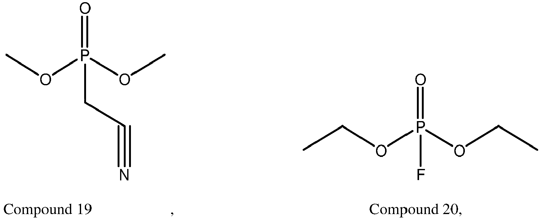


- In some embodiments, the mass percent A% of the phosphorus additive in the electrolytic solution satisfies the following condition: 0.05 ≤ A ≤ 10.
- In some embodiments, the electrolytic solution further includes a second additive. The second additive includes at least one of polynitrile compounds. A number of cyano groups in the polynitrile compounds is 2 to 4.
- In some embodiments, the polynitrile compounds include at least one of a dinitrile or a trinitrile.
- The dinitrile includes at least one of succinonitrile, glutaronitrile, adiponitrile, pimelonitrile, suberonitrile, 1,5-dicyanopentane, 1,6-dicyanohexane, tetramethylsuccinonitrile, or ethylene glycol bis(propionitrile) ether.
- The trinitrile includes at least one of 1,3,5-pentanetricarbonitrile, 1,2,3-propanetricarbonitrile, 1,3,6-hexanetricarbonitrile, 1,2,6-hexanetricarbonitrile, or 1,2,3-tris(2-cyanoethoxy)propane.
- In some embodiments, a mass percent of the second additive in the electrolytic solution is C%, and C satisfies the following condition: 0.5 ≤ C ≤ 10.
- In some embodiments, a mass percent of the first additive in the electrolytic solution is B%, and A, B, and C satisfy the following condition: A + C ≤ 5B.
- In some embodiments, the electrochemical device further includes a negative electrode plate. The negative electrode plate includes a negative active material. The negative active material includes a silicon material and a carbon material on a surface of the silicon material.
- According to a second aspect, this application provides an electronic device, including the electrochemical device.
- The electrochemical device and electronic device according to some embodiments of this application achieve at least the following beneficial effects:
- The phosphorus additive represented by Formula I is added in the electrolytic solution, and the phosphorus additive can participate in forming a thermally stable inorganic CEI film at a cathode electrode interphase to inhibit decomposition of the electrolytic solution in a high-temperature environment. Together with the first additive added in the electrolytic solution, the phosphorus additive can simultaneously inhibit the disruption caused by the metal deposition at an anode electrode interphase to the SEI film at the negative electrode. In addition, the positive active material with the M element can improve lattice stability of the positive active material and inhibit corrosion of the positive electrode material caused by acidic substances generated after decomposition of the phosphorus additive. The phosphorus additive represented by Formula I, the first additive, and the M element coordinate synergistically to improve the thermal stability of the electrochemical device under a high temperature.
- The phosphorus additive represented by Formula I is prone to decompose to generate acidic substances under high-temperature conditions, and is corrosive to the positive active material to some extent. Therefore, by controlling the phosphorus additive represented by Formula I and the M element to satisfy the condition of 0.0001 ≤ X/A ≤ 40, this application can exert the synergistic effect between the phosphorus additive represented by Formula I and the M element, and enhance the performance of resistance to thermal shock significantly.
- The electrolytic solution prepared herein further includes a second additive. The second additive can be adsorbed onto the cathode electrode interphase to effectively protect the positive active material and reduce side reactions at the cathode electrode interphase. However, under high-temperature conditions, both the phosphorus additive and the second additive deteriorate the anode electrode interphase to varying degrees. The first additive can effectively forms a solid-electrolyte interphase film (that is, SEI film) on the surface of the negative electrode. By controlling the mass percent of the phosphorus additive, the first additive, and the second additive to satisfy the relation A + C ≤ 2B, this application can effectively reduce the deterioration of the anode electrode interphase caused by the phosphorus additive and the second additive.
- To make the purposes, technical solutions, and advantages of this application clearer, the following describes this application in more detail with reference to embodiments. Understandably, the specific embodiments described herein are merely intended to explain this application, but are not intended to limit this application.
- During a thermal shock test on an electrochemical device, the temperature in the thermal shock test is usually higher than 100 °C. Such a high temperature greatly reduces stability of a cathode electrode interphase, and makes an electrolytic solution decompose massively at a positive electrode plate. At the same time, a positive active material layer of the positive electrode plate may collapse drastically, and a large amount of metal ions are deposited at a negative electrode plate to cause failure of an anode electrode interphase. Consequently, the electrolytic solution reacts violently at the anode electrode interphase simultaneously. Ultimately, the heat accumulated continuously at the cathode and anode electrode interphases causes a battery to burn or explode.
- An embodiment of this application provides an electrochemical device. From the positive active material of the positive electrode plate comprising a specific element, the stability of the positive active material is enhanced. In addition, a phosphorus additive is added into the electrolytic solution to protect the positive electrode plate, and an ester additive (a first additive to be mentioned later) is added into the electrolytic solution to protect the negative electrode plate, thereby enhancing the thermal stability of the cathode and anode electrode interphases. The performance of the electrochemical device in resisting thermal shocks is enhanced from three dimensions: the material of the positive electrode plate, the cathode electrode interphase, and the anode electrode interphase.
- The electrochemical device according to an embodiment of this application includes a positive electrode plate, a negative electrode plate, and an electrolytic solution. The positive electrode plate includes a positive current collector and a positive active material layer disposed on a surface of the positive current collector. The negative electrode plate includes a negative current collector and a negative active material layer disposed on a surface of the negative current collector. The electrolytic solution is in contact with a positive active material layer and a negative active material layer separately, and performs ion exchange to enable charging and discharging of the electrochemical device.
- In the electrochemical device, (1) the electrolytic solution includes a phosphorus additive represented by Formula I:

- In the Formula I, R1, R2, and R3 each are one independently selected from halogen, a cyano group, a sulfonic acid group, an aldehyde group, a silicon group, a substituted C1 to C6 alkoxy, an unsubstituted C1 to C6 alkoxy, a substituted C1 to C6 alkyl, an unsubstituted C1 to C6 alkyl, a substituted C2 to C6 alkenyl, an unsubstituted C2 to C6 alkenyl, a substituted C2 to C6 alkynyl, an unsubstituted C2 to C6 alkynyl, a substituted C6 to C12 aryl, or an unsubstituted C6 to C12 aryl, where when substituted, a substituent is halogen.
- A mass percent of the phosphorus additive represented by Formula I in the electrolytic solution is A%.
- (2) The electrolytic solution further includes a first additive. The first additive includes at least one of fluoroethylene carbonate (FEC) or vinylene carbonate (VC).
- (3) The positive active material layer includes a positive active material. The positive active material includes an M element. The M element includes at least one of Al, Mg, Ti, or B; a mass percent of the M element in the positive active material is X%; and A and X satisfy the following condition: 0.0001 ≤ X/A ≤ 40. When the X/A ratio is greater than 40 or the X/A ratio is less than 0.0001, the stability of the electrochemical device in resisting thermal shocks is reduced, being hardly able to meet the requirement on the thermal shock stability.
- The phosphorus additive represented by Formula I is added in the electrolytic solution to form a thermally stable inorganic cathode electrolyte interphase (CEI) film at a cathode electrode interphase to inhibit decomposition of the electrolytic solution in a high-temperature environment. Together with the first additive added in the electrolytic solution, the phosphorus additive can simultaneously inhibit the disruption caused by the metal deposition at an anode electrode interphase to the solid-electrolyte interphase (SEI) film. In addition, the positive active material with the M element can improve lattice stability of the positive active material and inhibit corrosion of the positive electrode material caused by acidic substances generated after decomposition of the phosphorus additive. The phosphorus additive represented by Formula I, the first additive, and the M element coordinate synergistically to improve the thermal stability of the electrochemical device under a high temperature.
- In some embodiments, the phosphorus additive represented by Formula I includes at least one of the following compounds:


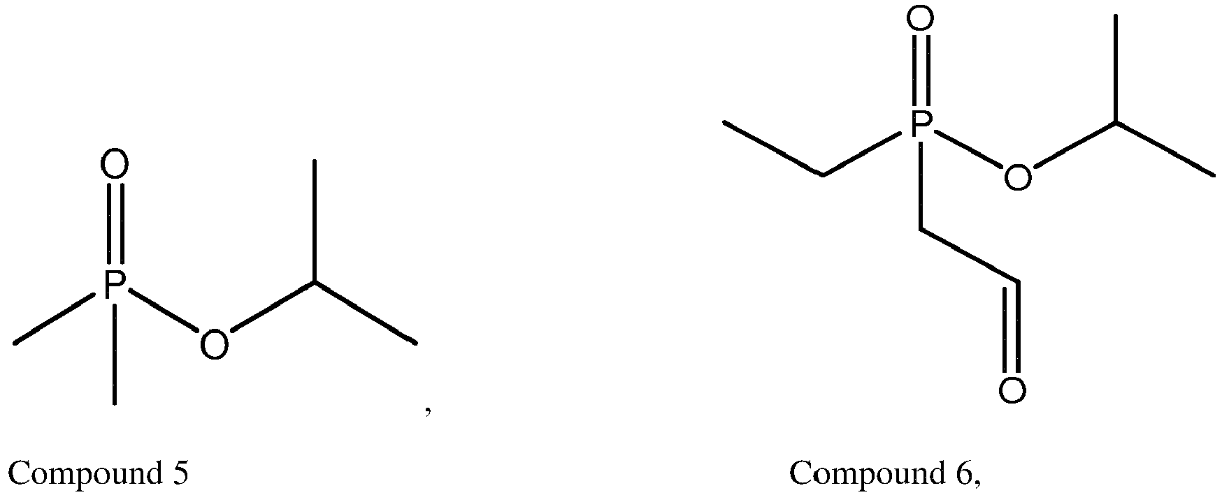


- In some embodiments, the mass percent A% of the phosphorus additive represented by Formula I in the electrolytic solution satisfies the following condition: 0.05 ≤ A ≤ 10, for example, may be 0.05, 2, 4, 5, 6, 7, 8, or 10. When the mass percent A% of the phosphorus additive represented by Formula I in the electrolytic solution is less than 0.05%, the phosphorus additive represented by Formula I is unable to effectively form an inorganic CEI film at the cathode electrode interphase, thereby making limited improvement in resistance to thermal shocks. When the mass percent A% of the phosphorus additive represented by Formula I in the electrolytic solution is higher than 10%, the high-content phosphorus additive represented by Formula I decomposes in the electrochemical device to produce a large amount of acidic substances, promotes decomposition of the conductive lithium salt to generate heat, corrodes the positive active material, impairs the thermal stability of the positive active material, and in turn, impairs the performance of the electrochemical device in resisting thermal shocks.
- In some embodiments, the electrolytic solution further includes a second additive. The second additive includes at least one of polynitrile compounds. A number of cyano groups in the polynitrile compounds is 2 to 4. The second additive can be adsorbed onto the cathode electrode interphase to effectively protect the positive active material and reduce side reactions at the cathode electrode interphase.
- In some embodiments, the polynitrile compounds include at least one of a dinitrile or a trinitrile.
- Optionally, the dinitrile includes at least one of succinonitrile, glutaronitrile, adiponitrile, pimelonitrile, suberonitrile, 1,5-dicyanopentane, 1,6-dicyanohexane, tetramethylsuccinonitrile, or ethylene glycol bis(propionitrile) ether.
- Optionally, the trinitrile includes at least one of 1,3,5-pentanetricarbonitrile, 1,2,3-propanetricarbonitrile, 1,3,6-hexanetricarbonitrile, 1,2,6-hexanetricarbonitrile, or 1,2,3-tris(2-cyanoethoxy)propane.
- In some embodiments, a mass percent of the second additive in the electrolytic solution is C%, and C satisfies the following condition: 0.5 ≤ C ≤ 10. For example, C may be 0.5, 1, 3, 5, 7, 8, 9, or 10. When the mass percent C% of the second additive in the electrolytic solution is less than 0.5%, the second additive is not enough to meet the requirement of optimizing the thermal stability of the electrochemical device. When the mass percent C% of the second additive in the electrolytic solution is greater than 10%, the content of the second additive is excessive, and hard to bring more optimization for the thermal stability of the electrochemical device, thereby resulting in waste.
- Under high-temperature conditions, both the phosphorus additive represented by Formula I and the second additive deteriorate the anode electrode interphase to varying degrees. The first additive can inhibit disruption of the SEI film at the negative electrode caused by metal deposition at the anode electrode interphase. Therefore, the mass percent of the phosphorus additive, the first additive, and the second additive needs to be controlled to fall within an appropriate range. In some embodiments, a mass percent of the first additive in the electrolytic solution is B%, and A, B, and C satisfy the following condition: A + C ≤ 2B. When the sum of A and C is greater than 2B, the content of the first additive is not enough to provide sufficient protection for the anode electrode interphase.
- In some embodiments, the negative active material layer includes a negative active material. The negative active material includes a silicon material and a carbon material on a surface of the silicon material. A silicon-based material expands greatly in volume during lithiation. Excessive expansion leads to exposure of a new surface of the active material and gives rise to more side reactions. The structure described above can effectively alleviate the expansion of the silicon-based active material.
- In some embodiments, the silicon material includes at least one of elemental silicon, a silicon-carbon composite, or a silicon-oxygen composite.
- In some embodiments, the carbon material includes graphite. Graphite itself can provide a specific lithiation capacity. Used as a cushion layer, the graphite is relatively stable in structure, and can withstand continuous expansion and shrinkage of the silicon-based material. In some embodiments, the graphite includes at least one of artificial graphite or natural graphite.
- The electrolytic solution further includes a lithium salt and a nonaqueous organic solvent.
- The lithium salt is not particularly limited herein, and the lithium salt may be any lithium salt well known in the art as long as the purposes of this application can be achieved. For example, the lithium salt may include at least one of LiTFSI, LiPF6, LiBF4, LiAsF6, LiClO4, LiB(C6H5)4, LiCH3SO3, LiCF3SO3, LiN(SO2CF3)2, LiC(SO2CF3)3, or LiPO2F2.
- The nonaqueous solvent is not particularly limited herein either as long as the purposes of this application can be achieved. For example, the nonaqueous solvent may include at least one of a carbonate compound, a carboxylate compound, an ether compound, another organic solvent, or the like. For example, the carbonate compound may include at least one of ethylene carbonate (EC), diethyl carbonate (DEC), dimethyl carbonate (DMC), dipropyl carbonate (DPC), methyl propyl carbonate (MPC), ethylene propyl carbonate (EPC), ethyl methyl carbonate (MEC), propylene carbonate (PC), butylene carbonate (BC), vinyl ethylene carbonate (VEC), 1,2-difluoroethylene carbonate, 1,1-difluoroethylene carbonate, 1,1,2-trifluoroethylene carbonate, 1,1,2,2-tetrafluoroethylene carbonate, 1-fluoro-2-methyl ethylene, 1-fluoro-1-methyl ethylene carbonate, 1,2-difluoro-1-methyl ethylene carbonate, 1,1,2-trifluoro-2-methyl ethylene carbonate, trifluoromethyl ethylene carbonate, or the like.
- The positive active material is not particularly limited herein as long as the purposes of this application can be achieved. For example, the positive active material may include at least one of lithium cobalt oxide, lithium manganese oxide, lithium iron phosphate, lithium iron manganese phosphate, lithium nickel cobalt manganese oxide, lithium nickel cobalt aluminum oxide, or lithium nickel manganese oxide.
- The positive active material layer further includes a positive conductive agent and/or a positive binder. The positive conductive agent is not particularly limited herein as long as the purposes of this application can be achieved. For example, the positive conductive agent may include at least one of conductive carbon black, acetylene black, Ketjen black, graphite sheets, graphene, carbon nanotubes, or carbon fibers. The positive binder is not particularly limited herein as long as the purposes of this application can be achieved. For example, the positive binder may include at least one of polyvinylidene fluoride, poly(vinylidene fluoride-co-hexafluoropropylene), polyacrylonitrile, polyacrylate, polyacrylic acid, polyacrylic acid sodium salt, poly(styrene-co-acrylate), poly(styrene-co-butadiene), polyamide, sodium carboxymethyl cellulose, polyvinyl acetate, polyvinylpyrrolidone, polyvinyl ether, polytetrafluoroethylene, polyhexafluoropropylene, or polymethyl methacrylate.
- The positive current collector is not particularly limited in this application. The positive current collector may be any positive current collector well known in the art such as an aluminum foil, an aluminum alloy foil, or a composite current collector.
- The negative active material is not particularly limited herein as long as the purposes of this application can be achieved. For example, the negative active material may include at least one of crystalline carbon, non-crystalline carbon, silicon, a silicon-oxygen compound, a silicon-carbon compound, or a silicon alloy.
- The negative active material layer may further include a negative conductive agent and/or a negative binder. The negative conductive agent is not particularly limited herein as long as the purposes of this application can be achieved. For example, the negative conductive agent may include at least one of carbon black, acetylene black, Ketjen black, graphite sheets, graphene, carbon nanotubes, carbon fibers, or carbon nanowires. The negative binder is not particularly limited herein as long as the purposes of this application can be achieved. For example, the negative binder may include at least one of carboxymethyl cellulose (CMC), polyacrylic acid, polyacrylic acid sodium salt, polyacrylate, polyvinylpyrrolidone, polyaniline, polyimide, polyamide imide, polysiloxane, styrene-butadiene rubber, epoxy resin, polyester resin, polyurethane resin, or polyfluorene.
- The negative current collector is not particularly limited herein as long as the purposes of this application can be achieved. For example, the negative current collector may include at least one of a copper foil, a nickel foil, or a carbon-based current collector.
- The electrochemical device further includes a separator. The separator is disposed between the positive electrode plate and the negative electrode plate to prevent a short circuit between the positive electrode plate and the negative electrode plate. The separator may include a polyethylene (PE) film or a polypropylene (PP) film. The electrochemical device further includes a positive tab, a negative tab, and an outer package. After the positive electrode plate, the separator, and the negative electrode plate are stacked sequentially or are stacked on one side and wound, the positive electrode plate is connected to the positive tab, and the negative electrode plate is connected to the negative tab to form an electrode assembly. The electrode assembly is disposed in an inner space of the outer package. The positive tab and the negative tab are led from the inner space of the outer package to the outer space of the outer package, so that the positive tab and the negative tab can be electrically connected to an external circuit. Subsequently, an electrolytic solution is injected into the inner space of the outer package, and the outer package is closed to form an electrochemical device. The outer package may be an aluminum plastic film outer package.
- An embodiment of this application further provides an electronic device, including the electrochemical device.
- The electronic device is not particularly limited in this application, and may be any electronic device known in the prior art. In some embodiments, the electronic device includes, but is not limited to, a notebook computer, pen-inputting computer, mobile computer, e-book player, portable phone, portable fax machine, portable photocopier, portable printer, stereo headset, video recorder, liquid crystal display television set, handheld cleaner, portable CD player, mini CD-ROM, transceiver, electronic notepad, calculator, memory card, portable voice recorder, radio, backup power supply, motor, automobile, motorcycle, power-assisted bicycle, bicycle, lighting appliance, toy, game console, watch, electric tool, flashlight, camera, large household battery, lithium-ion capacitor, and the like.
- The following describes this application in more detail with reference to specific embodiments by using a lithium-ion battery as an example of the electrochemical device.
- Thermal shock test: Charge a lithium-ion battery under test at a constant current of 0.5 C under a 25 °C condition until a voltage of 4.45 V, and then charge the battery at a constant voltage (CV) until a current of 0.025 C. Place the lithium-ion battery under test vertically in a box, heat up the battery to a specified temperature at a speed of 5±2 °C/min,, and hold on for 100 minutes. A criterion for determining pass of the test is: The lithium-ion battery under test does not catch fire or explode during 100-minute constant-temperature storage. The batteries are tested in groups, each group containing 3 batteries. If all 3 batteries pass the test, it is considered that this group of lithium-ion batteries passes the thermal shock test under the specified temperature.
- Dissolve lithium cobalt oxide (molecular formula: LiCoO2) as a positive active material, polyvinylidene difluoride (PVDF) as a positive binder, and conductive carbon black (Super-P) as a positive conductive agent in N-methyl-pyrrolidone (NMP) at a mass ratio of 96: 2: 2. Mix the ingredients well to make a positive slurry. Coat a 12 µm-thick positive current collector aluminum foil with the positive slurry evenly, bake the aluminum foil at 120 °C for 1 hour, and then perform compaction and cutting to obtain a positive electrode plate.
- In each embodiment and comparative embodiment, add the M element into the positive slurry, and stir evenly. Coat a foil with the slurry according to the foregoing steps to obtain a positive electrode plate with the M element.
- Dissolve artificial graphite (or natural graphite and a silicon-carbon composite) as a negative active material, sodium carboxymethylcellulose (CMC) as a negative binder, and styrene-butadiene rubber as a negative binder in water at a mass ratio of 85: 2: 13. Mix and stir well to obtain a negative slurry. Coat a 12 µm-thick negative current collector copper foil with the negative slurry evenly. Bake the copper foil at 120 °C for 1 hour to obtain a negative electrode plate, and then perform compaction and cutting to obtain a negative electrode plate.
- Mix ethylene carbonate and diethyl carbonate at a mass ratio of 3: 7, and add LiPF6 at a concentration of 1 mol/L into the mixture to obtain an base electrolyte.
- In each embodiment and comparative embodiment, add the phosphorus additive represented by Formula I, the first additive, and the second additive into the base electrolyte correspondingly to obtain an electrolytic solution.
- Use a polypropylene film as a separator. Stack the positive electrode plate, the separator, and the negative electrode plate in sequence, and position the separator between the positive electrode plate and the negative electrode plate to separate the positive electrode plate from the negative electrode plate, and then wind the stacked structure. Connect a positive tab to the positive electrode plate, and connect a negative tab to the negative electrode plate to obtain an electrode assembly. Put the electrode assembly into the inner space of the outer package, where the outer package is an aluminum foil packaging bag. Lead the positive tab and the negative tab from the inner space of the outer package to the outer space of the outer package. Bake the packaged electrode assembly at 80 °C to dehydrate, and inject an electrolytic solution into the inner space of the outer package. Perform steps such as vacuum packaging, standing, chemical formation, and shaping to obtain a lithium-ion battery.
- The lithium-ion batteries in each embodiment and comparative embodiment are prepared according to the above method and tested.
- In Comparative Embodiment 1-1 to Comparative Embodiment 1-2 and Embodiment 1-1 to Embodiment 1-9, the negative active material includes graphite, the electrolytic solution includes the phosphorus additive represented by Formula I and the first additive, and the positive active material includes anelement Al. The mass percent of the phosphorus additive represented by Formula I, the first additive, and the element Al is shown in Table 1.
Table 1 Item Phosphorus additive represented by Formula I A(%) First additive B(%) Element x (%) X/A Thermal shock temperature (°C) Comparative Embodiment 1-1 Compound 7 2 FEC 2 Al 0.0005 0.00005 97 Embodiment 1-1 Compound 7 2 FEC 2 Al 0.0002 0.0001 109 Embodiment 1-2 Compound 7 2 FEC 2 Al 0.005 0.0025 110 Embodiment 1-3 Compound 7 0.5 FEC 2 Al 0.005 0.01 113 Embodiment 1-4 Compound 7 0.1 FEC 2 Al 0.005 0.05 115 Embodiment 1-5 Compound 7 0.05 FEC 2 Al 0.05 1 121 Embodiment 1-7 Compound 7 0.05 FEC 2 Al 0.8 16 114 Embodiment 1-8 Compound 7 0.05 FEC 2 Al 1.5 30 113 Embodiment 1-9 Compound 7 0.05 FEC 2 Al 2 40 110 Comparative Embodiment 1-2 Compound 7 0.05 FEC 2 Al 2.2 44 100 - In Table 1, according to Comparative Embodiment 1-1 and Comparative Embodiment 1-2, when the X/A ratio is greater than 40 or less than 0.0001, the performance of the lithium-ion battery in resisting thermal shocks is inferior, and the lithium-ion battery fails just at a relatively low temperature. By contrast, in Embodiment 1-1 to Embodiment 1-9, the lithium-ion battery exhibits relatively high performance in resisting thermal shocks because a synergistic effect is exerted between the phosphorus additive represented by Formula I and the M element in the positive active material. The phosphorus additive represented by Formula I can be decomposed into a CEI film at the positive electrode interphase, and increase the content of inorganic compounds in the CEI film. The inorganic compounds in the CEI film are not prone to decompose under high-temperature conditions, thereby improving the performance of the electrochemical device in resisting thermal shocks. The M element added in the positive active material can strengthen the stability of the positive active material and enhance the performance of resistance to thermal shocks. However, the phosphorus additive represented by Formula I is prone to decompose to generate acidic substances under high-temperature conditions, and is corrosive to the positive active material to some extent. Therefore, the ratio of the phosphorus additive represented by Formula I to the M element needs to be controlled to fall within a specified range to exert the maximum effect of the phosphorus additive represented by Formula I and the M element, and enhance the performance of resistance to thermal shocks significantly.
- In Comparative Embodiment 2-1 to Comparative Embodiment 2-2 and Embodiment 2-1 to Embodiment 2-17, the negative active material includes graphite, and the electrolytic solution includes the phosphorus additive represented by Formula I and the first additive. The first additive is FEC, and the mass percent B% of FEC is 2%. The positive active material includes an element Al, and the mass percent X% of the elementAl is 0.005%. The mass percen A% of the phosphorus additive represented by Formula I in each embodiment and comparative embodiment is shown in Table 2.
Table 2 Item Phosphorus additive represented by Formula I A(%) Thermal shock temperature (°C) Comparative Embodiment 2-1 Compound 7 0.01 108 Embodiment 2-1 Compound 7 0.05 110 Embodiment 1-4 Compound 7 0.1 115 Embodiment 2-2 Compound 7 1 116 Embodiment 2-3 Compound 7 3 117 Embodiment 2-4 Compound 7 5 115 Embodiment 2-5 Compound 7 10 110 Comparative Embodiment 2-2 Compound 10 11 103 Embodiment 2-6 Compound 11 1 119 Embodiment 2-7 Compound 13 1 121 Embodiment 2-8 Compound 14 1 115 Embodiment 2-9 Compound 17 1 124 Embodiment 2-10 Compound 19 1 123 Embodiment 2-11 Compound 20 1 115 Embodiment 2-12 Compound 22 1 126 Embodiment 2-13 Compound 11 + compound 13 1+1 119 Embodiment 2-14 Compound 14 + compound 16 1+1 125 Embodiment 2-15 Compound 17 + compound 3 1+1 124 Embodiment 2-16 Compound 14 + compound 6 1+1 129 Embodiment 2-17 Compound 11 + compound 3 + compound 18 1+1+1 125 - In Table 2, by adding one or more of the phosphorus additives represented by Formula I into the electrolytic solution, the purpose of improving the performance of the lithium-ion battery in resisting thermal shocks can be achieved. In Comparative Embodiment 2-1, when the mass percent of the additive represented by Formula I is less than 0.05%, the low-content phosphorus additive represented by Formula I is unable to effectively form an inorganic CEI film at the cathode electrode interphase, and the improvement in the performance of resistance to thermal shocks is limited. In Comparative Embodiment 2-2, when the mass percent of the additive represented by Formula I is higher than 10%, the high-content phosphorus additive represented by Formula I decomposes in the lithium-ion battery to produce a large amount of acidic substances, promotes decomposition of the conductive lithium salt in the electrolytic solution to generate heat, corrodes the positive and negative active materials, impairs the thermal stability of the positive and negative active materials, and in turn, impairs the performance of the lithium-ion battery in resisting thermal shocks.
- In Comparative Embodiment 3-1 to Comparative Embodiment 3-2 and Embodiment 3-1 to Embodiment 3-11, the negative active material includes graphite, and the electrolytic solution includes the phosphorus additive represented by Formula I and the first additive. The phosphorus additive represented by Formula I is a compound 13, and the mass percent A% of the compound 13 is 1%. The first additive is FEC, and the mass percent B% of FEC is 2%. The positive active material includes an element Al, and the mass percent X% of the element Al is 0.005%. The electrolytic solution in each embodiment and comparative embodiment further includes a second additive, and the mass percent of the second additive is shown in Table 3.
Table 3 Item Second additive C (%) Thermal shock temperature (°C) Embodiment 2-7 / / 121 Embodiment 3-1 Succinonitrile 0.1 121 Embodiment 3-2 Succinonitrile 0.5 122 Embodiment 3-3 Succinonitrile 1 126 Embodiment 3-4 Succinonitrile 3 127 Embodiment 3-5 Succinonitrile 5 131 Embodiment 3-6 Succinonitrile 10 132 Embodiment 3-7 Succinonitrile 12 132 Embodiment 3-8 Succinonitrile + adiponitrile 1+1 126 Embodiment 3-9 Adiponitrile + 1,2,3-propanetricarbonitrile 1+1 127 Embodiment 3-10 1,3,6-hexanetricarbonitrile + 1,2,3-tris(2-cyanoethoxy)propane 1+1 127 Embodiment 3-11 1,2,6-hexanetricarbonitrile + adiponitrile 1+1 128 Embodiment 3-12 Succinonitrile + adiponitrile + 1,3,6-hexanetric arbonitrile 1+1+2 128 Embodiment 3-13 Suberonitrile + adiponitrile + 1,2,6-hexanetric arbonitrile 1+1+3 129 - In Embodiment 3-1 to Embodiment 3-11, the second additive is added on the basis of Embodiment 2-7. The second additive is an effective positive electrode protection additive, and can be adsorbed onto the cathode electrode interphase to reduce side reactions at the cathode electrode interphase. In Embodiment 3-1, when the mass percent of the second additive is relatively low, no effective protection is implemented for the positive electrode plate. By contrast, in Embodiment 3-7, when the mass percent of the second additive is excessive, no more improvement is made in the stability to thermal shocks on the lithium-ion battery. Therefore, a preferred range of the second additive is 0.5% ≤ C% ≤ 10%.
- In Comparative Embodiment 4-1 to Comparative Embodiment 4-4 and Embodiment 4-1 to Embodiment 4-5, the negative active material includes graphite, and the positive active material includes an element Al. The mass percent X% of Al is 0.005%. The electrolytic solution includes the phosphorus additive represented by Formula I, the first additive, and the second additive. The type and mass percent of the phosphorus additive represented by Formula I, the first additive, and the second additive are shown in Table 4.
Table 4 Additive represented by Formula I A (%) First additive B (%) Second additive C (%) A + C ≤ 2B Thermal shock temperature (°C) Embodiment 3-10 Compound 13 1 FEC 2 1,3,6-hexanetricarbonitrile + 1,2,3-tris(2-cyanoethoxy)propane 2 Yes 127 Embodiment 4-1 Compound 21 1 FEC + VC 2+2 Adiponitrile 1 Yes 121 Embodiment 4-2 Compound 21 2 FEC + VC 2+2 Adiponitrile 1 Yes 123 Embodiment 4-3 Compound 21 1 FEC + VC 2+2 Adiponitrile 0.5 Yes 120 Embodiment 4-4 Compound 21 1 FEC + VC 2+2 Adiponitrile 3 Yes 129 Embodiment 4-5 Compound 21 1 FEC + VC 1+1 Adiponitrile 1 Yes 121 Comparative Embodiment 4-1 Compound 21 1 FEC + VC 0.3+0.3 Adiponitrile 1 No 108 Comparative Embodiment 4-2 Compound 21 1 FEC 0.1 Adiponitrile 1 No 110 Comparative Embodiment 4-3 Compound 21 1 VC 0.5 Adiponitrile 1 No 107 Comparative Embodiment 4-4 Compound 21 1 FEC 4 Adiponitrile 8 No 108 - In Table 4, according to Embodiment 4-1 to Embodiment 4-5, when A, B, and C satisfy the relation A + C ≤ 2B, the performance of the lithium-ion battery in resisting thermal shocks is relatively high. When the value of A+C is excessive and greater than 2B, the performance of the lithium-ion battery in resisting thermal shocks will be influenced. The first additive is an effective negative electrode film-forming (that is, SEI film) additive. The phosphorus additive represented by Formula I and the second additive deteriorate the anode electrode interphase to different degrees under high-temperature conditions. Therefore, in Comparative Embodiment 4-1 to Comparative Embodiment 4-4, when the mass percent of the phosphorus additive represented by Formula I and the second additive is relatively high and no effective negative electrode protection additive (that is, the first additive) is available for protection, the negative electrode plate will fail early in the thermal shock test, and in turn, the thermal shock test will be influenced.
- In Embodiment 5-1 to Embodiment 5-3, the electrolytic solution includes the phosphorus additive represented by Formula I and the first additive. The phosphorus additive represented by Formula I is a compound 7, and the mass percent A% of the compound 7 is 2%. The first additive is FEC, and the mass percent B% of FEC is 2%. The positive active material includes an element Al, and the mass percent X% of the element Al is 0.002 %. The specific type and mass percent of the negative active material are shown in Table 5.
Table 5 Item Negative active material Thermal shock temperature (°C) Embodiment 1-1 Artificial graphite 109 Embodiment 5-1 Silicon-carbon composite 113 Embodiment 5-2 20 wt% silicon-carbon composite + 80 wt% artificial graphite 118 Embodiment 5-3 30 wt% silicon-carbon composite + 70 wt% artificial graphite 120 - In Table 5, as can be seen from Embodiments 5-1 to 5-3 and Embodiment 1-1, when the negative active material includes a silicon material and graphite, the performance of the lithium-ion battery in resisting thermal shocks is enhanced to some extent.
- In the description of this application, a list of items referred to by the terms such as "at least one of", "at least one thereof" and other similar terms may mean any combination of the listed items. For example, if items A and B are listed, the phrases "at least one of A and B" and "at least one of A or B" mean: A alone; B alone; or both A and B. In another example, if items A, B, and C are listed, the phrases "at least one of A, B, and C" and "at least one of A, B, or C" mean: A alone; B alone; C alone; A and B (excluding C); A and C (excluding B); B and C (excluding A); or all of A, B, and C.
- In the description of this application, understandably, a direction or a positional relationship indicated by the terms such as "up", "down", "left", and "right" is merely intended for ease of describing this application and for brevity of the description, but not intended to indicate or imply that the indicated device or component is necessarily located in the specified position or constructed or operated in the specified direction or position. Therefore, the terms depicting the positional relationship are for illustration only, but not to be understood as any limitation on this patent. A person of ordinary skill in the art may understand the specific meanings of such terms depending on specific situations.
- The foregoing descriptions are merely embodiments of this application, but are not intended to limit this application. Any modifications, equivalent substitutions, and improvements made without departing from the principles of this application still fall within the protection scope of this application.
Claims (15)
- An electrochemical device, compring a positive electrode plate and an electrolytic solution; wherein,
the electrolytic solution comprises a phosphorus additive, and the phosphorus additive is at least one selected from compounds represented by Formula I: in the Formula I, R1, R2, and R3 each are one independently selected from halogen, a cyano group, a sulfonic acid group, an aldehyde group, a silicon group, a substituted C1 to C6 alkoxy, an unsubstituted C1 to C6 alkoxy, a substituted C1 to C6 alkyl, an unsubstituted C1 to C6 alkyl, a substituted C2 to C6 alkenyl, an unsubstituted C2 to C6 alkenyl, a substituted C2 to C6 alkynyl, an unsubstituted C2 to C6 alkynyl, a substituted C6 to C12 aryl, or an unsubstituted C6 to C12 aryl, wherein when substituted, a substituent is halogen;a mass percent of the phosphorus additive represented by Formula I in the electrolytic solution is A%;the electrolytic solution further comprises a first additive, and the first additive comprises at least one of fluoroethylene carbonate or vinylene carbonate; andthe positive electrode plate comprises a positive active material; the positive active material comprises an M element; the M element comprises at least one of Al, Mg, Ti, or B; a mass percent of the M element in the positive active material is X%; and 0.0001 ≤ X/A ≤ 40.
 - The electrochemical device according to claim 1, wherein R1, R2, and R3 each are one independently selected from an F element, the unsubstituted C1 to C6 alkoxy, the substituted C1 to C6 alkyl, the unsubstituted C1 to C6 alkyl, the substituted C2 to C6 alkenyl, or the unsubstituted C2 to C6 alkenyl, wherein when substituted, a substituent is the F element.
- The electrochemical device according to claim 1 or 2, wherein the phosphorus additive comprises at least one of the following compounds:


- The electrochemical device according to any one of claims 1 to 3, wherein 0.05 ≤ A ≤ 10.
- The electrochemical device according to any one of claims 1 to 4, wherein the electrolytic solution further comprises a second additive, and the second additive comprises at least one of polynitrile compounds; and
a number of cyano groups in the polynitrile compounds is 2 to 4. - The electrochemical device according to claim 5, wherein the polynitrile compounds comprise at least one of a dinitrile or a trinitrile;the dinitrile comprises at least one of succinonitrile, glutaronitrile, adiponitrile, pimelonitrile, suberonitrile, 1,5-dicyanopentane, 1,6-dicyanohexane, tetramethylsuccinonitrile, or ethylene glycol bis(propionitrile) ether; andthe trinitrile comprises at least one of 1,3,5-pentanetricarbonitrile, 1,2,3-propanetricarbonitrile, 1,3,6-hexanetricarbonitrile, 1,2,6-hexanetricarbonitrile, or 1,2,3-tris(2-cyanoethoxy)propane.
- The electrochemical device according to claim 5 or 6, wherein a mass percent of the second additive in the electrolytic solution is C%, and 0.5 ≤ C ≤ 10.
- The electrochemical device according to claim 7, wherein a mass percent of the first additive in the electrolytic solution is B%, and A + C ≤ 5B.
- The electrochemical device according to any one of claims 1 to 8, wherein the electrochemical device further comprises a negative electrode plate, the negative electrode plate comprises a negative active material; and the negative active material comprises a silicon material and a carbon material on a surface of the silicon material.
- The electrochemical device according to claim 9, wherein the carbon material comprises graphite.
- The electrochemical device according to claim 10, wherein the graphite comprises at least one of artificial graphite or natural graphite.
- The electrochemical device according to claim 9, wherein the silicon material comprises at least one of elemental silicon, a silicon-carbon composite, or a silicon-oxygen composite.
- The electrochemical device according to any one of claims 5 to 12, wherein the second additive comprises at least one of succinonitrile, glutaronitrile, adiponitrile, pimelonitrile, suberonitrile, 1,5-dicyanopentane, 1,6-dicyanohexane, tetramethylsuccinonitrile, or ethylene glycol bis(propionitrile).
- The electrochemical device according to any one of claims 5 to 13, wherein the second additive comprises at least one of 1,3,5-pentanetricarbonitrile, 1,2,3-propanetricarbonitrile, 1,3,6-hexanetricarbonitrile, 1,2,6-hexanetricarbonitrile, or 1,2,3-tris(2-cyanoethoxy)propane.
- An electronic device, wherein the electronic device comprises:
the electrochemical device according to any one of claims 1 to 14.
Applications Claiming Priority (1)
| Application Number | Priority Date | Filing Date | Title |
|---|---|---|---|
| CN202211250451.1A CN115312865B (en) | 2022-10-13 | 2022-10-13 | Electrochemical device and electronic apparatus |
Publications (1)
| Publication Number | Publication Date |
|---|---|
| EP4354543A1 true EP4354543A1 (en) | 2024-04-17 |
Family
ID=83868482
Family Applications (1)
| Application Number | Title | Priority Date | Filing Date |
|---|---|---|---|
| EP23202923.1A Pending EP4354543A1 (en) | 2022-10-13 | 2023-10-11 | Electrochemical device and electronic device |
Country Status (3)
| Country | Link |
|---|---|
| US (1) | US20240154168A1 (en) |
| EP (1) | EP4354543A1 (en) |
| CN (1) | CN115312865B (en) |
Citations (2)
| Publication number | Priority date | Publication date | Assignee | Title |
|---|---|---|---|---|
| CN106450438A (en) * | 2016-10-17 | 2017-02-22 | 广州天赐高新材料股份有限公司 | Lithium-ion battery electrolyte and lithium ion battery with the same |
| CN113273013A (en) * | 2019-01-14 | 2021-08-17 | 巴特尔纪念研究院 | Local super-concentrated electrolyte for silicon anodes |
Family Cites Families (4)
| Publication number | Priority date | Publication date | Assignee | Title |
|---|---|---|---|---|
| KR102398690B1 (en) * | 2019-01-24 | 2022-05-17 | 주식회사 엘지에너지솔루션 | Lithium secondary battery |
| CN112448034A (en) * | 2019-09-05 | 2021-03-05 | 东莞市杉杉电池材料有限公司 | Non-aqueous electrolyte for high-voltage lithium ion battery and lithium ion battery |
| KR20230082635A (en) * | 2020-10-05 | 2023-06-08 | 놈스 테크놀로지스, 인크. | Lithium-ion Battery Electrolyte Additives |
| CN115117452B (en) * | 2022-08-30 | 2022-12-06 | 深圳新宙邦科技股份有限公司 | Lithium ion battery |
-
2022
- 2022-10-13 CN CN202211250451.1A patent/CN115312865B/en active Active
-
2023
- 2023-10-11 EP EP23202923.1A patent/EP4354543A1/en active Pending
- 2023-10-12 US US18/379,188 patent/US20240154168A1/en active Pending
Patent Citations (2)
| Publication number | Priority date | Publication date | Assignee | Title |
|---|---|---|---|---|
| CN106450438A (en) * | 2016-10-17 | 2017-02-22 | 广州天赐高新材料股份有限公司 | Lithium-ion battery electrolyte and lithium ion battery with the same |
| CN113273013A (en) * | 2019-01-14 | 2021-08-17 | 巴特尔纪念研究院 | Local super-concentrated electrolyte for silicon anodes |
Also Published As
| Publication number | Publication date |
|---|---|
| CN115312865A (en) | 2022-11-08 |
| CN115312865B (en) | 2023-03-28 |
| US20240154168A1 (en) | 2024-05-09 |
Similar Documents
| Publication | Publication Date | Title |
|---|---|---|
| US8158285B2 (en) | Electrolyte solvent for improving safety of battery and lithium secondary battery comprising the same | |
| EP4404320A1 (en) | Electrolyte, electrochemical device comprising same, and electronic device | |
| TWI384668B (en) | Electrolyte, battery and method of forming passivation layer | |
| US20160181659A1 (en) | Electrolyte solution and lithium ion battery using said electrolyte solution | |
| EP3317911B1 (en) | Li-ion battery electrolyte with reduced impedance build-up | |
| US8709665B2 (en) | Nonaqueous secondary battery with nitrile group-containing compound | |
| EP4231407A1 (en) | Electrolyte solution, secondary battery comprising same, and preparation method for secondary battery | |
| CN116207351B (en) | Electrolyte, lithium secondary battery and electrical device | |
| EP4456232A1 (en) | Electrochemical device and electronic device | |
| US20240290973A1 (en) | Electrode plate, lithium-ion battery, battery module, battery pack and electric device | |
| US20220223915A1 (en) | Electrolyte, electrochemical device including same, and electronic device | |
| EP2613394B1 (en) | Non-aqueous electrolyte composition and non-aqueous electrolyte secondary battery | |
| CN115312892A (en) | Electrochemical device and electronic apparatus | |
| JP7263679B2 (en) | Non-aqueous electrolyte for batteries and lithium secondary batteries | |
| CN118120091A (en) | Lithium secondary battery | |
| US20240421355A1 (en) | Non-aqueous electrolyte, secondary battery, battery module, battery pack, and electrical device | |
| US20240021864A1 (en) | Electrolyte, secondary battery, battery module, battery pack and electrical device | |
| JP7200465B2 (en) | Non-aqueous electrolyte for batteries and lithium secondary batteries | |
| US20240154168A1 (en) | Electrochemical device and electronic device | |
| CN119695277B (en) | Electrolyte and battery | |
| JP7201074B2 (en) | Electrolyte for secondary battery and secondary battery | |
| US20240178437A1 (en) | Nonaqueous secondary battery and method for producing nonaqueous secondary battery | |
| KR101433662B1 (en) | electrolyte for lithium secondary battery and lithium secondary battery using the same | |
| US10818972B2 (en) | Electrolyte solution for lithium secondary battery | |
| JP2023132195A (en) | Non-aqueous electrolyte for batteries, lithium secondary battery precursor, lithium secondary battery, and method for producing lithium secondary battery |
Legal Events
| Date | Code | Title | Description |
|---|---|---|---|
| PUAI | Public reference made under article 153(3) epc to a published international application that has entered the european phase |
Free format text: ORIGINAL CODE: 0009012 |
|
| STAA | Information on the status of an ep patent application or granted ep patent |
Free format text: STATUS: REQUEST FOR EXAMINATION WAS MADE |
|
| 17P | Request for examination filed |
Effective date: 20231011 |
|
| AK | Designated contracting states |
Kind code of ref document: A1 Designated state(s): AL AT BE BG CH CY CZ DE DK EE ES FI FR GB GR HR HU IE IS IT LI LT LU LV MC ME MK MT NL NO PL PT RO RS SE SI SK SM TR |