EP4354424A1 - Composite molded body, method for manufacturing same, and composite sound absorbing material - Google Patents
Composite molded body, method for manufacturing same, and composite sound absorbing material Download PDFInfo
- Publication number
- EP4354424A1 EP4354424A1 EP22820231.3A EP22820231A EP4354424A1 EP 4354424 A1 EP4354424 A1 EP 4354424A1 EP 22820231 A EP22820231 A EP 22820231A EP 4354424 A1 EP4354424 A1 EP 4354424A1
- Authority
- EP
- European Patent Office
- Prior art keywords
- molded body
- composite
- composite molded
- absorbing material
- thickness
- Prior art date
- Legal status (The legal status is an assumption and is not a legal conclusion. Google has not performed a legal analysis and makes no representation as to the accuracy of the status listed.)
- Pending
Links
- 239000002131 composite material Substances 0.000 title claims abstract description 361
- 239000011358 absorbing material Substances 0.000 title claims abstract description 159
- 238000000034 method Methods 0.000 title claims description 96
- 238000004519 manufacturing process Methods 0.000 title claims description 13
- 239000000835 fiber Substances 0.000 claims abstract description 340
- 238000010521 absorption reaction Methods 0.000 claims abstract description 156
- 239000011148 porous material Substances 0.000 claims abstract description 26
- 230000035699 permeability Effects 0.000 claims description 65
- 229920002678 cellulose Polymers 0.000 claims description 51
- 239000001913 cellulose Substances 0.000 claims description 51
- 239000002002 slurry Substances 0.000 claims description 22
- 238000000465 moulding Methods 0.000 claims description 19
- 239000002121 nanofiber Substances 0.000 claims description 14
- 239000000463 material Substances 0.000 claims description 12
- 229920002239 polyacrylonitrile Polymers 0.000 claims description 7
- 238000007493 shaping process Methods 0.000 claims description 6
- 239000004760 aramid Substances 0.000 claims description 5
- 229920003235 aromatic polyamide Polymers 0.000 claims description 5
- 229920002101 Chitin Polymers 0.000 claims description 4
- 229920001661 Chitosan Polymers 0.000 claims description 4
- 229920002994 synthetic fiber Polymers 0.000 claims description 3
- 239000012209 synthetic fiber Substances 0.000 claims description 3
- 238000009423 ventilation Methods 0.000 abstract 4
- 239000010410 layer Substances 0.000 description 66
- 230000000694 effects Effects 0.000 description 28
- 238000011282 treatment Methods 0.000 description 28
- 229920000139 polyethylene terephthalate Polymers 0.000 description 24
- 239000005020 polyethylene terephthalate Substances 0.000 description 24
- 206010061592 cardiac fibrillation Diseases 0.000 description 20
- 230000002600 fibrillogenic effect Effects 0.000 description 20
- 230000000704 physical effect Effects 0.000 description 20
- 239000007787 solid Substances 0.000 description 16
- 239000007858 starting material Substances 0.000 description 16
- 230000000052 comparative effect Effects 0.000 description 15
- 239000011165 3D composite Substances 0.000 description 14
- 239000006185 dispersion Substances 0.000 description 11
- 238000011156 evaluation Methods 0.000 description 11
- 239000007788 liquid Substances 0.000 description 11
- 238000005259 measurement Methods 0.000 description 11
- XLYOFNOQVPJJNP-UHFFFAOYSA-N water Substances O XLYOFNOQVPJJNP-UHFFFAOYSA-N 0.000 description 10
- 229920003043 Cellulose fiber Polymers 0.000 description 8
- 230000001747 exhibiting effect Effects 0.000 description 8
- 239000004745 nonwoven fabric Substances 0.000 description 8
- 229920005989 resin Polymers 0.000 description 8
- 239000011347 resin Substances 0.000 description 8
- HMUNWXXNJPVALC-UHFFFAOYSA-N 1-[4-[2-(2,3-dihydro-1H-inden-2-ylamino)pyrimidin-5-yl]piperazin-1-yl]-2-(2,4,6,7-tetrahydrotriazolo[4,5-c]pyridin-5-yl)ethanone Chemical compound C1C(CC2=CC=CC=C12)NC1=NC=C(C=N1)N1CCN(CC1)C(CN1CC2=C(CC1)NN=N2)=O HMUNWXXNJPVALC-UHFFFAOYSA-N 0.000 description 7
- VZSRBBMJRBPUNF-UHFFFAOYSA-N 2-(2,3-dihydro-1H-inden-2-ylamino)-N-[3-oxo-3-(2,4,6,7-tetrahydrotriazolo[4,5-c]pyridin-5-yl)propyl]pyrimidine-5-carboxamide Chemical compound C1C(CC2=CC=CC=C12)NC1=NC=C(C=N1)C(=O)NCCC(N1CC2=C(CC1)NN=N2)=O VZSRBBMJRBPUNF-UHFFFAOYSA-N 0.000 description 7
- 239000004743 Polypropylene Substances 0.000 description 7
- 239000011230 binding agent Substances 0.000 description 7
- YLZOPXRUQYQQID-UHFFFAOYSA-N 3-(2,4,6,7-tetrahydrotriazolo[4,5-c]pyridin-5-yl)-1-[4-[2-[[3-(trifluoromethoxy)phenyl]methylamino]pyrimidin-5-yl]piperazin-1-yl]propan-1-one Chemical compound N1N=NC=2CN(CCC=21)CCC(=O)N1CCN(CC1)C=1C=NC(=NC=1)NCC1=CC(=CC=C1)OC(F)(F)F YLZOPXRUQYQQID-UHFFFAOYSA-N 0.000 description 6
- -1 Example 1-7 Chemical compound 0.000 description 6
- 239000000853 adhesive Substances 0.000 description 6
- 230000001070 adhesive effect Effects 0.000 description 6
- 239000000203 mixture Substances 0.000 description 6
- 229920000742 Cotton Polymers 0.000 description 5
- 238000010586 diagram Methods 0.000 description 5
- 239000006260 foam Substances 0.000 description 5
- XEEYBQQBJWHFJM-UHFFFAOYSA-N Iron Chemical compound [Fe] XEEYBQQBJWHFJM-UHFFFAOYSA-N 0.000 description 4
- NIPNSKYNPDTRPC-UHFFFAOYSA-N N-[2-oxo-2-(2,4,6,7-tetrahydrotriazolo[4,5-c]pyridin-5-yl)ethyl]-2-[[3-(trifluoromethoxy)phenyl]methylamino]pyrimidine-5-carboxamide Chemical compound O=C(CNC(=O)C=1C=NC(=NC=1)NCC1=CC(=CC=C1)OC(F)(F)F)N1CC2=C(CC1)NN=N2 NIPNSKYNPDTRPC-UHFFFAOYSA-N 0.000 description 4
- AFCARXCZXQIEQB-UHFFFAOYSA-N N-[3-oxo-3-(2,4,6,7-tetrahydrotriazolo[4,5-c]pyridin-5-yl)propyl]-2-[[3-(trifluoromethoxy)phenyl]methylamino]pyrimidine-5-carboxamide Chemical compound O=C(CCNC(=O)C=1C=NC(=NC=1)NCC1=CC(=CC=C1)OC(F)(F)F)N1CC2=C(CC1)NN=N2 AFCARXCZXQIEQB-UHFFFAOYSA-N 0.000 description 4
- VCUFZILGIRCDQQ-KRWDZBQOSA-N N-[[(5S)-2-oxo-3-(2-oxo-3H-1,3-benzoxazol-6-yl)-1,3-oxazolidin-5-yl]methyl]-2-[[3-(trifluoromethoxy)phenyl]methylamino]pyrimidine-5-carboxamide Chemical compound O=C1O[C@H](CN1C1=CC2=C(NC(O2)=O)C=C1)CNC(=O)C=1C=NC(=NC=1)NCC1=CC(=CC=C1)OC(F)(F)F VCUFZILGIRCDQQ-KRWDZBQOSA-N 0.000 description 4
- DKGAVHZHDRPRBM-UHFFFAOYSA-N Tert-Butanol Chemical compound CC(C)(C)O DKGAVHZHDRPRBM-UHFFFAOYSA-N 0.000 description 4
- 239000000654 additive Substances 0.000 description 4
- 238000001035 drying Methods 0.000 description 4
- 239000004094 surface-active agent Substances 0.000 description 4
- YIWGJFPJRAEKMK-UHFFFAOYSA-N 1-(2H-benzotriazol-5-yl)-3-methyl-8-[2-[[3-(trifluoromethoxy)phenyl]methylamino]pyrimidine-5-carbonyl]-1,3,8-triazaspiro[4.5]decane-2,4-dione Chemical compound CN1C(=O)N(c2ccc3n[nH]nc3c2)C2(CCN(CC2)C(=O)c2cnc(NCc3cccc(OC(F)(F)F)c3)nc2)C1=O YIWGJFPJRAEKMK-UHFFFAOYSA-N 0.000 description 3
- LDXJRKWFNNFDSA-UHFFFAOYSA-N 2-(2,4,6,7-tetrahydrotriazolo[4,5-c]pyridin-5-yl)-1-[4-[2-[[3-(trifluoromethoxy)phenyl]methylamino]pyrimidin-5-yl]piperazin-1-yl]ethanone Chemical compound C1CN(CC2=NNN=C21)CC(=O)N3CCN(CC3)C4=CN=C(N=C4)NCC5=CC(=CC=C5)OC(F)(F)F LDXJRKWFNNFDSA-UHFFFAOYSA-N 0.000 description 3
- 241000609240 Ambelania acida Species 0.000 description 3
- IJGRMHOSHXDMSA-UHFFFAOYSA-N Atomic nitrogen Chemical compound N#N IJGRMHOSHXDMSA-UHFFFAOYSA-N 0.000 description 3
- 235000017166 Bambusa arundinacea Nutrition 0.000 description 3
- 235000017491 Bambusa tulda Nutrition 0.000 description 3
- 241001330002 Bambuseae Species 0.000 description 3
- 244000025254 Cannabis sativa Species 0.000 description 3
- 235000012766 Cannabis sativa ssp. sativa var. sativa Nutrition 0.000 description 3
- 235000012765 Cannabis sativa ssp. sativa var. spontanea Nutrition 0.000 description 3
- 240000000797 Hibiscus cannabinus Species 0.000 description 3
- 235000015334 Phyllostachys viridis Nutrition 0.000 description 3
- FHKPLLOSJHHKNU-INIZCTEOSA-N [(3S)-3-[8-(1-ethyl-5-methylpyrazol-4-yl)-9-methylpurin-6-yl]oxypyrrolidin-1-yl]-(oxan-4-yl)methanone Chemical compound C(C)N1N=CC(=C1C)C=1N(C2=NC=NC(=C2N=1)O[C@@H]1CN(CC1)C(=O)C1CCOCC1)C FHKPLLOSJHHKNU-INIZCTEOSA-N 0.000 description 3
- NIXOWILDQLNWCW-UHFFFAOYSA-N acrylic acid group Chemical group C(C=C)(=O)O NIXOWILDQLNWCW-UHFFFAOYSA-N 0.000 description 3
- 239000010905 bagasse Substances 0.000 description 3
- 239000011425 bamboo Substances 0.000 description 3
- 235000009120 camo Nutrition 0.000 description 3
- 235000005607 chanvre indien Nutrition 0.000 description 3
- 238000010276 construction Methods 0.000 description 3
- 238000009826 distribution Methods 0.000 description 3
- 239000004744 fabric Substances 0.000 description 3
- 239000011487 hemp Substances 0.000 description 3
- 229920000642 polymer Polymers 0.000 description 3
- 229920001955 polyphenylene ether Polymers 0.000 description 3
- 238000003825 pressing Methods 0.000 description 3
- 238000012545 processing Methods 0.000 description 3
- 239000008213 purified water Substances 0.000 description 3
- 230000002829 reductive effect Effects 0.000 description 3
- 239000010902 straw Substances 0.000 description 3
- 239000000126 substance Substances 0.000 description 3
- 229920001187 thermosetting polymer Polymers 0.000 description 3
- DEXFNLNNUZKHNO-UHFFFAOYSA-N 6-[3-[4-[2-(2,3-dihydro-1H-inden-2-ylamino)pyrimidin-5-yl]piperidin-1-yl]-3-oxopropyl]-3H-1,3-benzoxazol-2-one Chemical compound C1C(CC2=CC=CC=C12)NC1=NC=C(C=N1)C1CCN(CC1)C(CCC1=CC2=C(NC(O2)=O)C=C1)=O DEXFNLNNUZKHNO-UHFFFAOYSA-N 0.000 description 2
- PAYRUJLWNCNPSJ-UHFFFAOYSA-N Aniline Chemical compound NC1=CC=CC=C1 PAYRUJLWNCNPSJ-UHFFFAOYSA-N 0.000 description 2
- 229920002488 Hemicellulose Polymers 0.000 description 2
- 239000004831 Hot glue Substances 0.000 description 2
- 229920000877 Melamine resin Polymers 0.000 description 2
- MKYBYDHXWVHEJW-UHFFFAOYSA-N N-[1-oxo-1-(2,4,6,7-tetrahydrotriazolo[4,5-c]pyridin-5-yl)propan-2-yl]-2-[[3-(trifluoromethoxy)phenyl]methylamino]pyrimidine-5-carboxamide Chemical compound O=C(C(C)NC(=O)C=1C=NC(=NC=1)NCC1=CC(=CC=C1)OC(F)(F)F)N1CC2=C(CC1)NN=N2 MKYBYDHXWVHEJW-UHFFFAOYSA-N 0.000 description 2
- JAWMENYCRQKKJY-UHFFFAOYSA-N [3-(2,4,6,7-tetrahydrotriazolo[4,5-c]pyridin-5-ylmethyl)-1-oxa-2,8-diazaspiro[4.5]dec-2-en-8-yl]-[2-[[3-(trifluoromethoxy)phenyl]methylamino]pyrimidin-5-yl]methanone Chemical compound N1N=NC=2CN(CCC=21)CC1=NOC2(C1)CCN(CC2)C(=O)C=1C=NC(=NC=1)NCC1=CC(=CC=C1)OC(F)(F)F JAWMENYCRQKKJY-UHFFFAOYSA-N 0.000 description 2
- 230000009471 action Effects 0.000 description 2
- 238000004220 aggregation Methods 0.000 description 2
- 230000002776 aggregation Effects 0.000 description 2
- 238000010009 beating Methods 0.000 description 2
- 238000005452 bending Methods 0.000 description 2
- 238000006243 chemical reaction Methods 0.000 description 2
- 239000003795 chemical substances by application Substances 0.000 description 2
- 239000003431 cross linking reagent Substances 0.000 description 2
- 238000005520 cutting process Methods 0.000 description 2
- 239000002270 dispersing agent Substances 0.000 description 2
- 230000004927 fusion Effects 0.000 description 2
- 238000010438 heat treatment Methods 0.000 description 2
- 230000002401 inhibitory effect Effects 0.000 description 2
- 229910052742 iron Inorganic materials 0.000 description 2
- 238000005304 joining Methods 0.000 description 2
- 230000007246 mechanism Effects 0.000 description 2
- 239000002184 metal Substances 0.000 description 2
- 229910052751 metal Inorganic materials 0.000 description 2
- 238000002156 mixing Methods 0.000 description 2
- 230000036961 partial effect Effects 0.000 description 2
- 238000003672 processing method Methods 0.000 description 2
- 239000004627 regenerated cellulose Substances 0.000 description 2
- 239000000523 sample Substances 0.000 description 2
- 239000000243 solution Substances 0.000 description 2
- 238000001179 sorption measurement Methods 0.000 description 2
- 238000009987 spinning Methods 0.000 description 2
- 238000005406 washing Methods 0.000 description 2
- 125000003903 2-propenyl group Chemical group [H]C([*])([H])C([H])=C([H])[H] 0.000 description 1
- CMLFRMDBDNHMRA-UHFFFAOYSA-N 2h-1,2-benzoxazine Chemical compound C1=CC=C2C=CNOC2=C1 CMLFRMDBDNHMRA-UHFFFAOYSA-N 0.000 description 1
- 244000198134 Agave sisalana Species 0.000 description 1
- 241001474374 Blennius Species 0.000 description 1
- 229920000298 Cellophane Polymers 0.000 description 1
- 241000218631 Coniferophyta Species 0.000 description 1
- 102000004190 Enzymes Human genes 0.000 description 1
- 108090000790 Enzymes Proteins 0.000 description 1
- UFHFLCQGNIYNRP-UHFFFAOYSA-N Hydrogen Chemical compound [H][H] UFHFLCQGNIYNRP-UHFFFAOYSA-N 0.000 description 1
- 229920000271 Kevlar® Polymers 0.000 description 1
- 229920000433 Lyocell Polymers 0.000 description 1
- 229920001410 Microfiber Polymers 0.000 description 1
- 240000000907 Musa textilis Species 0.000 description 1
- 229920002292 Nylon 6 Polymers 0.000 description 1
- 229920002302 Nylon 6,6 Polymers 0.000 description 1
- 229930040373 Paraformaldehyde Natural products 0.000 description 1
- 239000004952 Polyamide Substances 0.000 description 1
- 239000004734 Polyphenylene sulfide Substances 0.000 description 1
- 239000004372 Polyvinyl alcohol Substances 0.000 description 1
- 241000206607 Porphyra umbilicalis Species 0.000 description 1
- 229920001131 Pulp (paper) Polymers 0.000 description 1
- XUIMIQQOPSSXEZ-UHFFFAOYSA-N Silicon Chemical compound [Si] XUIMIQQOPSSXEZ-UHFFFAOYSA-N 0.000 description 1
- 229920002472 Starch Polymers 0.000 description 1
- 241000251555 Tunicata Species 0.000 description 1
- 229920001807 Urea-formaldehyde Polymers 0.000 description 1
- 230000000996 additive effect Effects 0.000 description 1
- 125000001931 aliphatic group Chemical group 0.000 description 1
- 229920000180 alkyd Polymers 0.000 description 1
- 239000008346 aqueous phase Substances 0.000 description 1
- 125000003118 aryl group Chemical group 0.000 description 1
- 238000004061 bleaching Methods 0.000 description 1
- 238000009835 boiling Methods 0.000 description 1
- 239000011248 coating agent Substances 0.000 description 1
- 238000000576 coating method Methods 0.000 description 1
- 150000001875 compounds Chemical class 0.000 description 1
- 238000004132 cross linking Methods 0.000 description 1
- 239000013078 crystal Substances 0.000 description 1
- 230000003247 decreasing effect Effects 0.000 description 1
- 230000007547 defect Effects 0.000 description 1
- 230000001419 dependent effect Effects 0.000 description 1
- 230000029087 digestion Effects 0.000 description 1
- 229910001873 dinitrogen Inorganic materials 0.000 description 1
- 238000011038 discontinuous diafiltration by volume reduction Methods 0.000 description 1
- 238000001523 electrospinning Methods 0.000 description 1
- 239000000839 emulsion Substances 0.000 description 1
- 230000007613 environmental effect Effects 0.000 description 1
- 230000002255 enzymatic effect Effects 0.000 description 1
- 239000003822 epoxy resin Substances 0.000 description 1
- 239000002657 fibrous material Substances 0.000 description 1
- 238000001914 filtration Methods 0.000 description 1
- 238000005187 foaming Methods 0.000 description 1
- HDNHWROHHSBKJG-UHFFFAOYSA-N formaldehyde;furan-2-ylmethanol Chemical compound O=C.OCC1=CC=CO1 HDNHWROHHSBKJG-UHFFFAOYSA-N 0.000 description 1
- 239000007849 furan resin Substances 0.000 description 1
- 238000000227 grinding Methods 0.000 description 1
- LNEPOXFFQSENCJ-UHFFFAOYSA-N haloperidol Chemical compound C1CC(O)(C=2C=CC(Cl)=CC=2)CCN1CCCC(=O)C1=CC=C(F)C=C1 LNEPOXFFQSENCJ-UHFFFAOYSA-N 0.000 description 1
- 239000011121 hardwood Substances 0.000 description 1
- 239000012535 impurity Substances 0.000 description 1
- 238000002347 injection Methods 0.000 description 1
- 239000007924 injection Substances 0.000 description 1
- 238000009413 insulation Methods 0.000 description 1
- 239000012948 isocyanate Substances 0.000 description 1
- 150000002513 isocyanates Chemical group 0.000 description 1
- 239000004761 kevlar Substances 0.000 description 1
- 229920005610 lignin Polymers 0.000 description 1
- 230000000670 limiting effect Effects 0.000 description 1
- 230000004807 localization Effects 0.000 description 1
- 238000000691 measurement method Methods 0.000 description 1
- JDSHMPZPIAZGSV-UHFFFAOYSA-N melamine Chemical compound NC1=NC(N)=NC(N)=N1 JDSHMPZPIAZGSV-UHFFFAOYSA-N 0.000 description 1
- 239000012528 membrane Substances 0.000 description 1
- 210000001724 microfibril Anatomy 0.000 description 1
- 239000000178 monomer Substances 0.000 description 1
- 229910052757 nitrogen Inorganic materials 0.000 description 1
- 239000003921 oil Substances 0.000 description 1
- 239000003960 organic solvent Substances 0.000 description 1
- 239000005011 phenolic resin Substances 0.000 description 1
- 229920003023 plastic Polymers 0.000 description 1
- 239000004033 plastic Substances 0.000 description 1
- 239000003495 polar organic solvent Substances 0.000 description 1
- 229920000747 poly(lactic acid) Polymers 0.000 description 1
- 229920000058 polyacrylate Polymers 0.000 description 1
- 229920002647 polyamide Polymers 0.000 description 1
- 229920000647 polyepoxide Polymers 0.000 description 1
- 229920000728 polyester Polymers 0.000 description 1
- 229920001721 polyimide Polymers 0.000 description 1
- 239000009719 polyimide resin Substances 0.000 description 1
- 239000004626 polylactic acid Substances 0.000 description 1
- 238000006116 polymerization reaction Methods 0.000 description 1
- 229920000098 polyolefin Polymers 0.000 description 1
- 229920006324 polyoxymethylene Polymers 0.000 description 1
- 229920000069 polyphenylene sulfide Polymers 0.000 description 1
- 229920001155 polypropylene Polymers 0.000 description 1
- 229920002635 polyurethane Polymers 0.000 description 1
- 239000004814 polyurethane Substances 0.000 description 1
- 229920005749 polyurethane resin Polymers 0.000 description 1
- 229920002451 polyvinyl alcohol Polymers 0.000 description 1
- 239000000843 powder Substances 0.000 description 1
- 238000002203 pretreatment Methods 0.000 description 1
- 230000002265 prevention Effects 0.000 description 1
- 230000008569 process Effects 0.000 description 1
- 239000000047 product Substances 0.000 description 1
- 239000012264 purified product Substances 0.000 description 1
- 230000009467 reduction Effects 0.000 description 1
- 238000007670 refining Methods 0.000 description 1
- 238000010008 shearing Methods 0.000 description 1
- 239000010703 silicon Substances 0.000 description 1
- 229910052710 silicon Inorganic materials 0.000 description 1
- 238000004513 sizing Methods 0.000 description 1
- 239000002904 solvent Substances 0.000 description 1
- 239000007921 spray Substances 0.000 description 1
- 239000008107 starch Substances 0.000 description 1
- 235000019698 starch Nutrition 0.000 description 1
- 239000002344 surface layer Substances 0.000 description 1
- 229920005992 thermoplastic resin Polymers 0.000 description 1
- 238000012546 transfer Methods 0.000 description 1
- 238000009827 uniform distribution Methods 0.000 description 1
- 229920006337 unsaturated polyester resin Polymers 0.000 description 1
- 230000004304 visual acuity Effects 0.000 description 1
Images



Classifications
-
- G—PHYSICS
- G10—MUSICAL INSTRUMENTS; ACOUSTICS
- G10K—SOUND-PRODUCING DEVICES; METHODS OR DEVICES FOR PROTECTING AGAINST, OR FOR DAMPING, NOISE OR OTHER ACOUSTIC WAVES IN GENERAL; ACOUSTICS NOT OTHERWISE PROVIDED FOR
- G10K11/00—Methods or devices for transmitting, conducting or directing sound in general; Methods or devices for protecting against, or for damping, noise or other acoustic waves in general
- G10K11/16—Methods or devices for protecting against, or for damping, noise or other acoustic waves in general
- G10K11/162—Selection of materials
- G10K11/168—Plural layers of different materials, e.g. sandwiches
-
- G—PHYSICS
- G10—MUSICAL INSTRUMENTS; ACOUSTICS
- G10K—SOUND-PRODUCING DEVICES; METHODS OR DEVICES FOR PROTECTING AGAINST, OR FOR DAMPING, NOISE OR OTHER ACOUSTIC WAVES IN GENERAL; ACOUSTICS NOT OTHERWISE PROVIDED FOR
- G10K2210/00—Details of active noise control [ANC] covered by G10K11/178 but not provided for in any of its subgroups
- G10K2210/30—Means
- G10K2210/321—Physical
- G10K2210/3219—Geometry of the configuration
-
- G—PHYSICS
- G10—MUSICAL INSTRUMENTS; ACOUSTICS
- G10K—SOUND-PRODUCING DEVICES; METHODS OR DEVICES FOR PROTECTING AGAINST, OR FOR DAMPING, NOISE OR OTHER ACOUSTIC WAVES IN GENERAL; ACOUSTICS NOT OTHERWISE PROVIDED FOR
- G10K2210/00—Details of active noise control [ANC] covered by G10K11/178 but not provided for in any of its subgroups
- G10K2210/30—Means
- G10K2210/321—Physical
- G10K2210/3223—Materials, e.g. special compositions or gases
Definitions
- the present disclosure relates to a composite molded body and a method for producing it, and to a composite sound absorbing material.
- Noise from the engine or drive system traveling of an automobile generates various forms of noise including noise from the engine or drive system, road noise, and wind noise.
- Sound-absorbing materials have conventionally been used for the purpose of inhibiting noise emission in order to suppress such unwanted noise and create comfortable indoor automobile spaces.
- sounds that had not previously been considered to be noise have come to be recognized as noise.
- the frequency of noise depends on the sound source, and sound-absorbing materials suitable for different sound sources must therefore be used.
- porous sound-absorbing materials that are commonly used in vehicles, such as nonwoven fabrics and foam, while exhibiting an excellent sound absorption coefficient in the high frequency range, tend to have a smaller sound absorption coefficient at the low frequency end.
- air permeability-modifying layer a layer that modifies air permeability
- PTL 1 describes a textile-type composite sound absorbing material having a foam layer provided as an air permeability-modifying layer on a nonwoven fabric obtained by combining staple fibers of specific fineness, the material exhibiting an excellent sound absorption property at 800 Hz to 2000 Hz.
- PTL 2 discloses a composite sound absorbing material having a spunbond nonwoven fabric spot-bonded on a melamine foamed body using a hot-melt adhesive, and teaches that an excellent sound absorption property is exhibited in all frequency ranges if the thickness is slightly greater than 10 mm.
- the composite molded body of the present disclosure can be suitably used as an air permeability-modifying layer to provide excellent sound absorption properties across the low frequency to mid frequency range, and has excellent three-dimensional shapeability.
- the composite molded body of the disclosure comprises fibrillated fibers and staple fibers, and has a surface density of 30 g/m 2 to 1000 g/m 2 and an air permeability resistance per unit thickness of 15.0 s/(100 mL ⁇ mm) or lower.
- the composite molded body preferably has a structure in which staple fibers and fibrillated fibers are molded in a chemically or physically intertwined or mutually bonded state.
- the composite molded body has extremely low air permeability resistance since the dense structure has fine fiber gaps. When sound infiltrates through the gaps between the fibers, therefore, the composite molded body converts the vibrational energy of sound to friction with the ultrafine fibers, converting it to heat energy, while the composite molded body itself also undergoes membrane vibration, allowing further conversion to heat energy, so that it exhibits an excellent sound absorption property.
- the composite molded body of the disclosure comprises fibrillated fibers.
- fibrillated fiber refers to fibers having at least a partially branched structure.
- Fibrillated fibers are largely classified into two types: fibers that have been obtained by partially fracturing the structure of fibers without branch structures by using physical or chemical means, and fibers that have been fibrillated by intentionally creating fluff during spinning of the polymer compound.
- the former include microfibrillated cellulose (synonymous with CNF, cellulose nanofibers or cellulose fine fibers), synthetic pulp such as acryl pulp (fibrillated fibers of polyacrylonitrile) or aramid pulp, chitin nanofibers, chitosan nanofibers and silk nanofibers.
- An example of the latter is synthetic pulp produced by flash-spinning.
- Fibrillated fibers generally have a structure with partially narrowed fiber sizes compared to ordinary fibers without a branched structure, due to the method for their production. Fibrillated fibers consequently have larger surface area while also tending to have more of a curved structure.
- the fibrillated fibers in the composite molded body of the disclosure consequently exhibit an effect as a binder for joining together staple fibers by physical entanglement. Partially narrowed fibers help to adjust the air permeation of the composite molded body as a whole while contributing to sound absorption in the low frequency range.
- the fibrillated fibers are preferably at least one type selected from the group consisting of microfibrillated cellulose, acrylic pulp, aramid pulp, chitin nanofibers, chitosan nanofibers and silk nanofibers, and more preferably at least one type selected from the group consisting of microfibrillated cellulose and acrylic pulp made of polyacrylonitrile.
- Cellulose obtained from a cellulose starting material with a type II crystal structure is preferably used for microfibrillated cellulose, because the air permeability resistance per unit thickness, as described in detail below, will be lower.
- the fibrillation rate of the fibrillated fibers in the composite molded body is preferably 0.3% or higher. Within this range the effect as a binder will be sufficient, and the composite molded body will have a free-standing property, with low shedding of staple fibers from the composite molded body. Fibers narrowed by fibrillation also exhibit an effect of sound absorption in the low frequency range.
- the fibrillation rate of the fibrillated fiber is more preferably 0.5% or higher.
- the upper limit for the fibrillation rate is not particularly restricted but may be 100% or lower.
- the area fineness of the fibrillated fibers in the composite molded body is preferably 3.0% to 90%. Within this range the effect as a binder will be sufficient, and the composite molded body will have a free-standing property, with low shedding of staple fibers from the composite molded body.
- the area fineness of the fibrillated fibers is more preferably 5% to 50% and even more preferably 5% to 20%.
- the mean fiber length of the fibrillated fibers in the composite molded body is preferably 150 ⁇ m or greater. Within this range the effect as a binder will be sufficient, the sizes of pores formed in the composite molded body will not be too small, and suitable air permeability will be obtained.
- the mean fiber length of the fibrillated fibers is more preferably 200 ⁇ m or greater, even more preferably 250 ⁇ m or greater and most preferably 350 ⁇ m or greater.
- the upper limit for the mean fiber length is preferably 1000 ⁇ m or smaller in order to obtain excellent miscibility with staple fibers and a homogeneous molded article, and it is more preferably 750 ⁇ m or smaller and even more preferably 500 ⁇ m or smaller.
- the mean fiber length was measured using a fiber image analyzer (Morfi-Neo by TechPap Co.), with a normal fiber/fine fiber threshold of 100 ⁇ m.
- the mean fiber size of the fibrillated fibers in the composite molded body is primarily either the mean fiber size corresponding to trunk fiber portions of the fibrillated fibers (mean fiber size by Method A), or the mean fiber size including the microfibrous portions up to the fibrillated ends (mean fiber size by Method B).
- the mean fiber size by Method A is preferably 50 ⁇ m or smaller. Within this range, the sizes of pores formed in the composite molded body will not be too small, and suitable air permeability will be obtained.
- the mean fiber size of the fibrillated fibers by Method A is more preferably 30 ⁇ m or smaller, even more preferably 25 ⁇ m or smaller and most preferably 15 ⁇ m or smaller. The lower limit is not particularly restricted and may be 1.5 ⁇ m or greater for resolving power of the apparatus.
- the mean fiber size by Method B is preferably 1000 nm or lower. Within this range, entanglement with the staple fibers will be more likely to occur, helping to inhibit shedding of the fibers from the composite molded body.
- the mean fiber size of the fibrillated fibers as a whole by Method B is more preferably 800 nm or smaller, even more preferably 600 nm or smaller and most preferably 500 nm or smaller.
- the lower limit is not particularly restricted but is preferably 10 nm or greater, more preferably 20 nm or greater and even more preferably 30 nm or greater.
- the fibrillated fibers used in the composite molded body are microfibrillated cellulose.
- Cellulose fine fibers are cellulose fibers that have been micronized using at least one type of physical means, and the term is a generally synonymous with cellulose nanofibers, CNF, CeNF and MFC (microfibrillated cellulose).
- the starting material for microfibrillated cellulose may be a type I cellulose starting material, which includes wood pulp such as conifer pulp or hardwood pulp, and nonwood pulp.
- Nonwood pulp may be cotton pulp such as cotton linter pulp, or hemp pulp, bagasse pulp, kenaf pulp, bamboo pulp or straw pulp.
- Cotton pulp, hemp pulp, bagasse pulp, kenaf pulp, bamboo pulp and straw pulp are the refined pulp obtained from the respective starting materials of cotton lint, cotton linter, hemp abaca (usually from Ecuador or the Philippines), sisal, bagasse, kenaf, bamboo and straw, by refining steps such as delignification by digestion treatment and hemicellulose removal, and bleaching steps.
- Purified products of seaweed cellulose or sea squirt cellulose may also be used as starting materials for cellulose fine fibers.
- Type II cellulose starting materials include cut yarns of regenerated cellulose fiber and cut yarns of cellulose derivative fibers, for use as cellulose fine fiber starting materials, and cut yarns of regenerated cellulose or cellulose derivative superfine fibers obtained by electrospinning methods, for use as cellulose fine fiber starting materials or for cellulose fine fibers themselves.
- Such starting materials may be used alone or in mixtures of two or more different types.
- the mean fiber size can be adjusted by using multiple different starting materials in admixture.
- the starting material may be micronized to obtain microfibrillated cellulose.
- micronization means controlling the fiber length, fiber size, area fineness and fibrillation rate while sizing down the cellulose.
- the micronization treatment is preceded by a pretreatment step.
- a pretreatment step it is effective for the starting pulp to be subjected to autoclave treatment or enzyme treatment, or a combination thereof, while impregnated with water at a temperature of 100°C to 150°C, for conversion to a state that is easily micronized.
- Such pretreatment has the effect of not only reducing the load in the micronization treatment, but also of causing impurity components such as lignin and hemicellulose, which are present on the surface and in the gaps of the microfibrils forming the cellulose fibers, to be discharged into the aqueous phase, increasing the ⁇ -cellulose purity of the micronized fibers as a result, and it is therefore effective for increasing the heat resistance of the microfibrillated cellulose.
- the starting pulp is dispersed in water and micronized using a publicly known micronization device such as a beater, single disc refiner, double disc refiner or high-pressure homogenizer.
- a publicly known micronization device such as a beater, single disc refiner, double disc refiner or high-pressure homogenizer.
- the treatment concentration suitable for micronization will differ depending on the device used, and may therefore be set as desired.
- the fibrillation rate, area fineness, mean fiber length and mean fiber size of the microfibrillated cellulose can be controlled by the cellulose starting material, the pretreatment conditions prior to micronization treatment (for example, autoclave treatment, enzymatic treatment or beating treatment), the conditions for micronization treatment (selection of the type of device, operating pressure and number of passes), or a combination of the foregoing.
- the cellulose starting material, pretreatment and micronization can also be controlled by a combination of multiple different conditions.
- the method for multistage micronization is preferably multistage micronization using disc refiners with different disc constructions, or micronization with a high-pressure homogenizer after micronization with a disc refiner.
- the disc refiner used may be either a single disc refiner or double disc refiner.
- micronization in multiple stages using more than one disc refiner it is preferred to use at least two refiners having different disc constructions.
- Using refiners with different disc constructions will allow control of the various shape parameters for the microfibrillated cellulose, i.e. the fibrillation rate area fineness, mean fiber length and mean fiber size.
- Modifying the disc structure of the disc refiner is an effective means for controlling the shape parameters of the microfibrillated cellulose.
- the important features of a disc refiner structure are the blade width, groove width and the blade/groove ratio (the blade width divided by the groove width), with the blade/groove ratio being most important for production of fibrillated fibers. If the blade/groove ratio is low the cutting action on the fibers will be larger, thus reducing the fiber lengths, while if the blade/groove ratio is high the action of grinding (beating) the fibers will be greater, thus increasing the fibrillation rate.
- the blade/groove ratio is preferably 0.2 or higher, more preferably 0.4 or higher and most preferably 0.5 or higher. With a constant blade/groove ratio, smaller absolute values for the blade width and groove width will yield fine, homogeneous microfibrillated cellulose.
- the interblade distance For micronization with a disc refiner, it is important to control the distance between the two discs (the rotary blade and fixed blade). This distance will hereunder be referred to as the "interblade distance". Controlling the interblade distance will allow control of the mean fiber length of the microfibrillated cellulose, with a smaller interblade distance resulting in a smaller mean fiber length.
- the interblade distance is preferably 0.05 mm to 2.0 mm, and for post-treatment the interblade distance is preferably 0.05 mm to 1.0 mm.
- the interblade distance is gradually narrowed from a wide interblade distance to the target interblade distance, as such control will help to prevent clogging or overload of the device, and to yield cellulose fibers with a narrow distribution of fiber length and fiber size and high homogeneity.
- the degree of micronization can also be controlled by the number of times the cellulose passes through the disc section (hereunder referred to as "number of passes").
- number of passes is the number of times refiner treatment is carried out after the interblade distance has been set to the target value.
- the number of passes of the disc refiner is preferably 5 times or more, more preferably 20 times or more and even more preferably 40 times or more. A greater number of times is preferred since the distribution of fiber shapes will gradually converge to be constant, but from the standpoint of productivity, the upper limit for the number of passes is 300 times or less.
- the method for controlling the number of passes may be a method in which one tank is used for each refiner, and the slurry is circulated alone, controlling the number of passes based on the flow rate, or a method in which two tanks are used for each refiner, and the slurry is reciprocated between tanks while carrying out refiner treatment.
- the former method allows the equipment to be simplified. In the latter case, the cellulose reliably passes through the disc section during each treatment, allowing microfibrillated cellulose with higher homogeneity to be obtained.
- a high-pressure homogenizer has a greater effect of narrowing fibers than a disc refiner, and its combination with micronization using a disc refiner can yield narrow elongated cellulose fibers.
- Synthetic pulp can be obtained by a spin draw process on a prepared polymer, a flash prevention method from a solution or emulsion, a strip fiber method by uniaxial stretching of a regulation film, or a shear polymerization method in which a monomer is polymerized under shearing stress.
- Acrylic pulp may be BiPUL (registered trademark of Japan Exlan Co., Ltd.) and aramid pulp may be Kevlar (registered trademark of DuPont Corp.) or TIARA (registered trademark of Daicel Miraizu, Ltd.). It may also be produced by high-pressure homogenizer treatment, in the same manner as micronized cellulose.
- the composite molded body of the disclosure includes staple fibers in addition to fibrillated fibers.
- staple fibers means fibers made of a fibrous material and having fiber lengths of 10 mm or less.
- the staple fibers may be natural fibers, synthetic fibers or semisynthetic fibers.
- polymers composing staple fibers include thermoplastic resins such as polyolefins, polyesters, polyamides (aromatic or aliphatic), acrylic polymers, polyvinyl alcohol, polylactic acid, polyphenylene ether, polyoxymethylene and polyphenylene sulfide, and thermosetting resins such as epoxy resins, thermosetting modified polyphenylene ether resins, thermosetting polyimide resins, urea resins, allyl resins, silicon resins, benzoxazine resins, phenol resins, unsaturated polyester resins, bismaleimide-triazine resins, alkyd resins, furan resins, melamine resins, polyurethane resins and aniline resins.
- thermoplastic resins such as polyolefins, polyesters, polyamides (aromatic or aliphatic), acrylic polymers, polyvinyl alcohol, polylactic acid, polyphenylene ether, polyoxymethylene and polyphenylene sulfide
- thermosetting resins
- Staple fibers may be used alone or in combinations of more than one.
- Staple fibers are preferably selected in consideration of properties including heat resistance and chemical resistance, depending on the member in which they are to be applied, and it may be polypropylene, polyamide 6, polyamide 66, polyphenylene ether, polyethylene terephthalate, or combinations thereof. In consideration of moldability of the composite molded body, it preferably includes at least polyethylene terephthalate fibers.
- the mean fiber size of the staple fibers is preferably 0.1 ⁇ m to 10.0 ⁇ m. If the staple fibers used have a mean fiber size in this range, they will uniformly blend with the fibrillated fibers, producing a composite molded body with a sufficiently micronized interior. By using staple fibers with a fiber size of 10.0 ⁇ m or smaller, it will be easier for the staple fibers to vibrate, more easily providing a sound absorption effect.
- the mean fiber size of the staple fibers is more preferably 1.0 ⁇ m to 8.0 ⁇ m and even more preferably 1.0 ⁇ m to 6.0 ⁇ m.
- the fiber size of the staple fibers will usually be expressed as dtex (or T), in which case the mean fiber size may be considered to be a value calculated from the density of the substance composing the fibers.
- the fiber length (also known as "cut length") of the staple fibers is preferably 5.0 mm or less. Three-dimensional molding will be further facilitated within this range, helping to obtain a homogeneous composite molded body and a more uniform sound absorption effect.
- the fiber length of the staple fibers is more preferably 4.0 mm or less and even more preferably 3.0 mm or less.
- the composite molded body preferably includes fibrillated fibers at 0.1 wt% or greater based on the total weight of the composite molded body. Within this range, the fibrillated fibers will be able to further contribute to sound absorption in the low frequency range. By including numerous fibrillated fibers, the strength of the composite molded body is increased and shedding of the fibers from the surface is reduced. The fibrillated fiber content may therefore be adjusted to match the desired sound absorption properties, but from the viewpoint of handleability of the composite molded body and of preventing shedding of the fibers, it is more preferably 5.0 wt% or greater and even more preferably 10.0 wt% or greater.
- the upper limit is preferably 50 wt% or lower, as this range will provide suitable air permeability without creating an overly dense structure of the composite molded body, and the average sound absorption over all frequencies will be increased.
- the upper limit is more preferably 40 wt% or lower, even more preferably 30 wt% or lower and most preferably 20 wt% or lower.
- the composite molded body preferably includes staple fibers at 50 wt% or greater based on the total weight of the composite molded body.
- a staple fiber content within this range will result in excellent sound absorption properties in the mid to high frequency bands.
- the staple fiber content is more preferably 60 wt% or greater, even more preferably 70 wt% or greater and most preferably 80 wt% or greater. Since the composite molded body must include fibrillated fibers, the upper limit for the staple fiber content is preferably 99.9 wt% or lower, more preferably 95 wt% or lower and even more preferably 90% or lower.
- the composite molded body has a surface density in the range of 30 g/m 2 to 1000 g/m 2 . Within this range it will be possible to mold a structure without critical defects, and the structure will be able to function as an air permeability-modifying layer. If the surface density is high the sound absorption property in the low frequency range will be higher, while if it is low the sound absorption property in the mid to high frequency range will be higher, and therefore the surface density is preferably selected in consideration of the frequency of sound to be absorbed.
- the surface density is preferably 30 g/m 2 to 500 g/m 2 , more preferably 50 g/m 2 to 500 g/m 2 and even more preferably 100 g/m 2 to 300 g/m 2 .
- the composite molded body has an air permeability resistance per unit thickness of 15.0 s/(100 mL ⁇ mm) or lower.
- the air permeability resistance (equivalent to the concept of air permeability or flow resistance) and thickness are measured by the following methods. Since the structure of the air permeability-modifying layer is often exceedingly thin, the thickness is often ignored in favor of evaluating the air permeability per unit area. However, without being limited to theory, it is thought that the sound absorption properties of the composite molded body of the disclosure are governed by two different mechanisms: viscosity resistance within the structure and film vibration, which means that limiting the air permeability resistance per unit thickness to a small value is important.
- the air permeability resistance per unit thickness is preferably 10.0 s/(100 mL ⁇ mm) or lower and more preferably 5.0 s/(100 mL ⁇ mm) or lower. Within this range, a high sound absorption coefficient can be obtained in a wide frequency range even with increased thickness of the composite molded body.
- the lower limit for the air permeability resistance per unit thickness is not particularly restricted but is preferably 0.001 s/(100 mL ⁇ mm) or higher, more preferably 0.01 s/(100 mL ⁇ mm) or higher and even more preferably 0.1 s/(100 mL ⁇ mm) or higher.
- the air permeability resistance can be adjusted by the mean fiber length and mean fiber size of the fibrillated fibers, and the mean fiber size of the staple fibers.
- the thickness of the composite molded body is preferably 100 ⁇ m to 2000 ⁇ m. Such a range can provide an excellent sound absorption property with a low volume of sound absorbing material.
- the thickness of the composite molded body is more preferably 200 ⁇ m to 1500 ⁇ m. It should be noted that the thickness cannot be controlled independently but rather, is highly dependent on the surface density.
- the method for controlling the thickness may be by either of two methods: control based on the material itself or control by processing.
- a method of controlling the thickness based on the material itself may be control of the fibrillated fiber content, the staple fiber size or the staple fiber type, such as increasing the fibrillated fiber content, thereby lowering the thickness due to closer bond distances between the staple fibers forming the frame.
- Control by processing may be reducing the thickness by pressing during molding of the composite molded body.
- such methods may be used alone or as combinations of different methods.
- the bulk density of the composite molded body is preferably 0.05 g/cm 3 to 0.50 g/cm 3 . If the bulk density is within this range it will be possible to obtain suitable air permeability to facilitate the sound absorption effect.
- the bulk density is more preferably 0.1 g/cm 3 to 0.4 g/cm 3 and even more preferably 0.15 g/cm 3 to 0.35 g/cm 3 .
- the bulk density can be controlled by adjusting the material thickness, the material thickness being adjustable by the method described above.
- the composite molded body can be easily formed into a three-dimensional structure, to form a structure having a homogeneous surface and being free of seams or gaps.
- three-dimensional structure as used herein means a structure for the composite molded body that is not two-dimensional (planar or flat), but instead has at least a curved structure (hereunder also referred to as either "three-dimensional” or "spatial structure").
- the air permeability-modifying layer When a flat air permeability-modifying layer such as a commonly used nonwoven fabric is applied in a three-dimensional structure, the air permeability-modifying layer is disposed on the sound absorbing material surface via cutting, bending and attaching, during which time partial creation of an overlapping structure, or gaps and folds, in the nonwoven fabric become unavoidable. This produces variation in the air permeability, making it impossible to obtain homogeneous sound absorption properties on all surfaces. If the composite molded body is processed three-dimensionally, however, the surface becomes uniform with a structure lacking seams or gaps, so that consistent sound absorption properties can be obtained on all surfaces of the composite molded body, even applied against a sound source with intricate shape, for an excellent overall sound absorption property.
- the method for producing the composite molded body of the disclosure is not particularly restricted, and may be a method that includes dispersing the staple fibers and fibrillated fibers in a liquid medium, and removal and drying of the solvent by filtration and pressing. Mixing the staple fibers and fibrillated fibers in a liquid medium allows a composite molded body with a more homogeneous internal structure to be obtained.
- a molding method as described above makes processing possible into any desired shape, preferably by a wet papermaking method or pulp molding method. Using a wet papermaking method can yield a two-dimensional flat molded article (i.e. a "nonwoven fabric"), while using a pulp molding method allows shaping into complex three-dimensional shapes. Several different pulp molding methods exist which are suitable depending on the desired molded article.
- Such methods include the Thick Wall method, in which a molded article having high load resistance is obtained with a very large film thickness of 5 mm to 10 mm, the Transfer Mold method, in which a smooth molded article having a surface with a film thickness of 3 mm to 5 mm is obtained, the Thermoformed Mold method, in which a complex shape with a film thickness of 1 mm to 3 mm is obtained, the PIM (Pulp Injection Mold) method, in which a complex shape is obtained using a boss or rib, as for ordinary plastic molded articles, and the PF (Pulp Forming) method, in which a lightweight, soft molded article is obtained by foaming in a die.
- Other systems not within this classification may also be employed, so long as they allow three-dimensional shaping.
- Various additives may also be added to the liquid medium during molding.
- the liquid medium used for molding is not particularly restricted, and a publicly known liquid medium such as water or an organic solvent may be used. While it is preferred to use water in consideration of handleability and low environmental load, a non-polar organic solvent with lower surface tension may be used for the purpose of preventing aggregation when drying and lowering the air permeability resistance per unit thickness. When water is used as the liquid medium, a surfactant may also be added to control the surface tension.
- a papermaking dispersant is a surfactant to facilitate defibration of the bundled staple fibers in a liquid medium or a viscous agent to adjust the viscosity of the liquid medium and prevent aggregation of the fibers, and it allows control of the air permeability resistance per unit thickness by improving the smoothness or homogeneity of the surface and providing uniformity in the internal structure. It should be noted that the added surfactant will also affect the surface tension of the liquid medium.
- a binder is an adhesive component such as starch, and by adhering together the fibers it allows control of the structural strength and air permeability resistance per unit thickness.
- a crosslinking agent is an isocyanate or polyurethane, and by chemically or physically crosslinking the intertwined points of the fibers it can prevent shedding of the fibers and adjust their strength.
- Such additives may be used alone or in combinations of two or more.
- the composite molded body of the disclosure can be suitably used as a sound absorbing material.
- the composite molded body of the disclosure may be used alone, or several sheets may be layered together for use. When used alone, it exhibits primarily a sound absorbing effect by viscosity resistance, providing sound absorption properties with low sound absorption in the low frequency range and increasing sound absorption coefficient with higher frequencies.
- the composite molded body of the disclosure preferably has a very high air permeability resistance per unit thickness, to exhibit an effect of sound insulation of certain frequencies.
- the composite molded body of the disclosure can be molded into any desired three-dimensional shape, it can be used not only in flat members but also members with complex three-dimensional shapes, allowing it to be suitably used as a sound absorbing material for automobiles having structural members or devices with complex shapes.
- Automobile structural members and devices include instrument panels, doors, roofs, floors, tire houses, engines, compressors and motors.
- the composite sound absorbing material of the disclosure has a structure with an air permeability-modifying layer on a support.
- the air permeability-modifying layer used may be a composite molded body of the disclosure.
- An air layer may also be provided behind the composite molded body (meaning at a location on the opposite side from the sound source).
- a sound absorption effect will thus be exhibited by film vibration in addition to viscosity resistance. That is, maximum sound absorption will be exhibited for specific frequencies, while also providing satisfactory sound absorption across the entire range of frequencies.
- the preferred use is as a sound absorbing material to provide a composite sound absorbing material exhibiting superior sound absorption properties.
- the structure of the support must be an air-permeable structure.
- a columnar structure may be employed to provide complete gaps behind the air permeability-modifying layer, or a porous material such as felt, a nonwoven fabric or foam may be used to obtain a composite sound absorbing material.
- a porous material such as felt, a nonwoven fabric or foam
- the composite molded body exhibits its own sound absorption effect while also acting as an air permeability-modifying layer. It is undesirable to use a structure without air permeability, such as a resin sheet lacking a foam structure, as the support.
- porous material as the support is preferred to allow regulation of the sound absorption properties.
- Using a material with high air permeability as the porous material can provide an excellent sound absorption effect across a wide range of frequencies, while using a material with poor air permeability can provide a particularly excellent sound absorption effect for specific frequencies.
- the porous material preferably has higher air permeability than the composite molded body.
- the index for air permeability may be the air permeability resistance per unit thickness, explained above. Examples of porous materials include, but are not limited to, publicly known porous materials such as nonwoven fabrics, felt and foam.
- the support preferably has a thickness of 5 mm or greater.
- the thickness of the support is the thickness of the structure with air permeability and does not include the thickness of the structure without air permeability.
- the support thickness is therefore preferably 6 mm or greater and most preferably 7 mm or greater.
- the upper limit is not particularly restricted, but from the viewpoint of reducing space requirements for the sound absorbing material, it is preferably 50 mm or smaller, more preferably 30 mm or smaller, even more preferably 10 mm or smaller and most preferably 8 mm or smaller.
- the composite molded body of the disclosure may be layered with the support by any of a variety of different means. Examples include a method of heating only the surface of the composite molded body with an IR heater, for joining by heat fusion, and a method of coating the composite molded body surface with a hot-melt adhesive using a curtain spray system, and then heating for heat fusion.
- the thickness of the air permeability-modifying layer in the composite sound absorbing material is controlled by changing the number of layers of the composite molded body or by changing the thickness per layer of the composite molded body (the composite molded body thickness described above), thereby allowing the sound absorption properties to be adjusted.
- Increasing the thickness of the air permeability-modifying layer lowers the air permeability of the structure as a whole, exhibiting a higher sound absorption effect for the low frequency range.
- Lower air permeability also tends to reduce the sound absorption effect for the high frequency range.
- the thickness of the air permeability-modifying layer is not particularly restricted, and may be adjusted to match a sound source whose sound is to be absorbed for satisfactory control of the frequency characteristic.
- the frequency dependence for sound absorption is lower in the former case (i.e. the maximum sound absorption coefficient is reduced and the average sound absorption across the entire frequency range is higher). In the latter case, however, frequency dependence is increased (i.e. the maximum sound absorption coefficient is increased and average sound absorption across the entire frequency range is lower), while a high sound absorption effect is also obtained at lower frequencies.
- the thickness of the air permeability-modifying layer and the method for controlling it may be adjusted according to the sound source whose sound is to be absorbed, or it may be used according to the purpose, to satisfactorily control the sound absorption properties.
- the low frequency reinforced thin composite sound absorbing material preferably has an overall structural thickness of 10 mm or smaller and a structure in which an air permeability-modifying layer and a porous material are layered, wherein:
- the low frequency reinforced thin composite sound absorbing material of the disclosure has excellent sound absorption properties in the low to mid frequency range despite the thin structure as mentioned above, while also exhibiting a sound absorption effect across a wide frequency range of 500 Hz to 6400 Hz.
- the sound absorption coefficient at 1000 Hz is preferably 0.4 or greater and more preferably 0.5 or greater.
- the average sound absorption at 800 Hz to 2000 Hz is preferably 0.5 or greater and more preferably 0.6 or greater.
- the average sound absorption at 500 Hz to 6400 Hz is preferably 0.4 or greater and more preferably 0.5 or greater.
- the structure of the air permeability-modifying layer i.e. the surface density, air permeability resistance and thickness of the air permeability-modifying layer.
- the surface density, air permeability resistance and thickness of the air permeability-modifying layer are the total values, i.e. the values measured when they are layered.
- the effects of controlling the values are the same effects obtained when controlling the surface density, air permeability resistance per unit thickness and thickness of the composite molded body, as described above.
- the surface density is preferably 150 g/m 2 to 300 g/m 2
- the air permeability resistance is preferably 0.5 s/100 mL to 1.5 s/100 mL and more preferably 1.0 s/100 mL to 1.5 s/100 mL
- the air permeability-modifying layer thickness is preferably 0.75 mm to 2.00 m and more preferably 0.75 mm to 2.00 m.
- the thickness of the porous material support may be arbitrarily adjusted depending on the air permeability-modifying layer.
- the low frequency reinforced thin composite sound absorbing material has a thickness of 10 mm or smaller for the overall structure.
- the sound absorption properties can also be controlled by controlling the thickness of the overall structure, similar to a common sound absorbing material. Since a structure with a large thickness is effective for sound absorption of low frequencies, the overall structure preferably has a larger thickness, the lower limit for the thickness being preferably 5.5 mm or greater, more preferably 7.0 mm or greater, even more preferably 8.0 mm or greater and most preferably 9.0 mm or greater.
- Mean fiber size (Method A and Method B), fibrillation rate and area fineness of fibrillated fibers
- the mean fiber size (Method A), fibrillation rate and area fineness of the fibrillated fibers were measured by the following procedures using an automatic fiber shape analyzer (MorFi Neo by Technidyne).
- the threshold values for the minimum fiber length and maximum fiber length during measurement were 100 ⁇ m and 1500 ⁇ m, respectively.
- the mean fiber size of the fibrillated fibers was measured by the following procedure using a specific surface area/pore distribution analyzer (NOVA-4200e by Quantachrome Instruments). Fibrillated fibers that aggregated by drying as fibrillated cellulose fine fibers were measured after the following pretreatment.
- the air permeability resistance of the composite molded body is the result of measuring the permeation time for 100 mL of air using a Gurley densometer (for example, a model G-B2C by Toyo Seiki Co., Ltd.), and it was measured by the following procedure.
- a Gurley densometer for example, a model G-B2C by Toyo Seiki Co., Ltd.
- the thickness of the composite molded body was measured by the following procedure.
- Air permeability resistance and thickness of the composite molded body were calculated from the surface density, based on the following definition.
- Air permeability resistance per unit thickness Air permeability resistance s / 100 mL / thickness mm
- Bulk density Surface density g / m 2 / thickness mm
- a circular disc with a diameter of 28.8 mm was cut out from each of the composite molded bodies of the Examples and Comparative Examples, and naturally layered against coarse felt with a thickness of 8.0 mm to form a composite sound absorbing material.
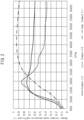
- the sound absorption coefficient of the composite sound absorbing material was measured according to JIS A 1405, using a DS-2000 normal incident sound absorption coefficient measuring system (Ono Sokki Co., Ltd.). The measurement was conducted with the composite molded body on the sound wave incident side. Some of the measurement results are shown in Fig. 1 .
- a circular disc with a diameter of 28.8 mm was cut out from each composite molded body of the Examples, and the sound absorption coefficient was measured according to JIS A 1405 using a DS-2000 normal incident sound absorption coefficient measuring system (Ono Sokki Co., Ltd.), with a 10.0 mm air layer provided underneath.
- a predetermined number of circular discs each with a diameter of 28.8 mm were cut out from each of the composite molded bodies of the Examples and Comparative Examples, and all were naturally layered against coarse felt with a thickness of 8.0 mm to form a low frequency reinforced thin composite sound absorbing material.
- the sound absorption coefficient of the composite sound absorbing material was measured according to JIS A 1405, using a DS-2000 normal incident sound absorption coefficient measuring system (Ono Sokki Co., Ltd.). The measurement was conducted with the composite molded body on the sound wave incident side. Some of the measurement results are shown in Fig. 2 .
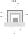
- Figs. 3 to 5 are schematic diagrams showing the structure of a three-dimensional composite sound absorbing material, and a schematic diagram illustrating the evaluation method.
- Felt (12) with a thickness of 8 mm and PP sheets (11, thickness: 1 mm) were attached to the outer sides of each of the composite molded bodies of the Examples and Comparative Examples using double-sided tape and a rapid bonding adhesive, to prepare a three-dimensional composite sound absorbing material (10).
- the three-dimensional composite sound absorbing material (10) was disposed covering a sound source (20) placed on a desk (30).
- the sound source used was a Bluetooth TM speaker.
- the speaker was connected to a smartphone, and an application (Tuning Fork Pro) was used to output 1045.7 Hz, 1478.9 Hz and 1974.1 Hz tones.
- the sound pressure at all frequencies was set to be 70 dB without the sound absorbing material.
- the ambient sound level was 48 dB.
- an evaluator (40) standing at a distance of 1.0 m from the side wall of the three-dimensional composite sound absorbing material (10) was asked to confirm the degree to which the sound level decreased (the percentage of the original sound level), and the average value for evaluations by 10 evaluators was used as the evaluation result for the sound absorption property.
- Fibrillated fibers of polyacrylonitrile (BiPUL, product of Japan Exlan Co., Ltd., 18% solid weight) were used as fibrillated fibers A.
- the results of evaluating the fibrillation rate, area fineness, mean fiber length and mean fiber size are shown in Table 1.
- ALabo Pulper (Aikawa Iron Works Co.) was used for simple dispersion, followed by delivery to a tank.
- the slurry was micronized while circulating with a single disc refiner (first stage) equipped with a disc having a 2.5 mm blade width and a 7.0 mm groove width, connected to the tank.
- the operation was completed when the total slurry amount had passed through the disc section 35 times, with an interblade distance of 1.0 mm.
- the slurry was then micronized while circulating with a single disc refiner (second stage) equipped with a disc having a 0.8 mm blade width and a 1.5 mm groove width.
- Fibrillated fibers B were subjected to further micronization treatment using a high-pressure homogenizer (NS015H by Niro Soavi). The slurry was treated in a batch style with five treatments. The results of evaluating the fibrillation rate, area fineness, mean fiber length and mean fiber size are shown in Table 1.
- Linter pulp as natural cellulose acquired from Japan Pulp and Paper Co.
- a Labo Pulper Aikawa Iron Works Co.
- the slurry was micronized while circulating with a single disc refiner (first stage) equipped with a disc having a 2.5 mm blade width and a 7.0 mm groove width, connected to the tank. Operation was initiated with an interblade distance of 1.0 mm, gradually narrowing the interblade distance to a final interblade distance of 0.05 mm.
- Fibrillated fibers A and PET staple fibers A were used to fabricate a composite molded body by the following procedure.
- the fibrillated fibers and staple fibers were added to purified water in a solid weight ratio of 20:80 to a final solid concentration of 0.5%, and the mixture was stirred with a household mixer for 4 minutes to prepare a slurry.
- the prepared slurry was loaded into in a batch paper machine (automatic square sheet machine by Kumagai Riki Kogyo Co., Ltd., 25 cm ⁇ 25 cm, 80 mesh) in which a filter cloth (TT35 by Shikishima Canvas Co., Ltd.) was set, to a surface density of 50 g/m 2 , after which paper-making (dewatering) was carried out with pressure reduction of 50 KPa relative to atmospheric pressure.
- a batch paper machine automated square sheet machine by Kumagai Riki Kogyo Co., Ltd., 25 cm ⁇ 25 cm, 80 mesh
- a filter cloth TT35 by Shikishima Canvas Co., Ltd.
- the aforementioned filter cloth was used to cover the surface of the wet concentrated composition on a filter cloth, and was detached from the wire and pressed for 1 minute at a pressure of 1 kg/cm 2 . It was then dried for about 120 seconds in a drum dryer set to a surface temperature of 130°C, to obtain a composite molded body S 1.
- a circular disc with a diameter of 28.8 mm was cut out from the obtained composite molded body, and naturally layered against coarse felt with a thickness of 8.0 mm to form a composite sound absorbing material.
- the physical properties of the obtained composite molded body, and the sound absorption properties of the composite sound absorbing material, are shown in Table 1.
- Composite molded body S2 was obtained by the same method as Example 1, except that PET fibers B (TA04N by Teijin, Ltd., fineness: 0.5 T, mean fiber size: 7.0 ⁇ m, cut length: 5 mm) were used as the staple fibers.
- a circular disc with a diameter of 28.8 mm was cut out from the obtained composite molded body, and naturally layered against coarse felt with a thickness of 8.0 mm to form a composite sound absorbing material.
- the physical properties of the obtained composite molded body, and the sound absorption properties of the composite sound absorbing material, are shown in Table 1.
- Composite molded body S3 was obtained by the same method as Example 1, except that the surface density was 100 g/m 2 .
- a circular disc with a diameter of 28.8 mm was cut out from the obtained composite molded body, and naturally layered against coarse felt with a thickness of 8.0 mm to form a composite sound absorbing material.
- the physical properties of the obtained composite molded body, and the sound absorption properties of the composite sound absorbing material, are shown in Table 1.
- Composite molded body S4 was obtained by the same method as Example 1, except that the solid weight ratio of the fibrillated fibers and staple fibers was 30:70. A circular disc with a diameter of 28.8 mm was cut out from the obtained composite molded body, and naturally layered against coarse felt with a thickness of 8.0 mm to form a composite sound absorbing material. The physical properties of the obtained composite molded body, and the sound absorption properties of the composite sound absorbing material, are shown in Table 1.
- Composite molded body S5 was obtained by the same method as Example 1, except that the surface density was 150 g/m 2 and the solid weight ratio of the fibrillated fibers and staple fibers was 10:90.
- a circular disc with a diameter of 28.8 mm was cut out from the obtained composite molded body, and naturally layered against coarse felt with a thickness of 8.0 mm to form a composite sound absorbing material.
- the physical properties of the obtained composite molded body, and the sound absorption properties of the composite sound absorbing material, are shown in Table 1.
- Composite molded body S6 was obtained by the same method as Example 1, except that fibrillated fibers B were used as the fibrillated fibers, and PET staple fibers C (TA04PN by Teijin, Ltd., fineness: 0.3 T, mean fiber size: 5.3 ⁇ m, cut length: 3 mm) were used as the staple fibers.
- a circular disc with a diameter of 28.8 mm was cut out from the obtained composite molded body, and naturally layered against coarse felt with a thickness of 8.0 mm to form a composite sound absorbing material.
- the physical properties of the obtained composite molded body, and the sound absorption properties of the composite sound absorbing material, are shown in Table 1.
- Composite molded body S7 was obtained by the same method as Example 1, except that fibrillated fibers C were used as the fibrillated fibers and the surface density was 100 g/m 2 .
- a circular disc with a diameter of 28.8 mm was cut out from the obtained composite molded body, and naturally layered against coarse felt with a thickness of 8.0 mm to form a composite sound absorbing material.
- the physical properties of the obtained composite molded body, and the sound absorption properties of the composite sound absorbing material, are shown in Table 1.
- Composite molded body S8 was obtained by the same method as Example 1, except that fibrillated fibers B were used as the fibrillated fibers, the surface density was 100 g/m 2 , and the solid weight ratio of the fibrillated fibers and staple fibers was 5:95.
- a circular disc with a diameter of 28.8 mm was cut out from the obtained composite molded body, and naturally layered against coarse felt with a thickness of 8.0 mm to form a composite sound absorbing material.
- the physical properties of the obtained composite molded body, and the sound absorption properties of the composite sound absorbing material, are shown in Table 2.
- Composite molded body S9 was obtained by the same method as Example 1, except that fibrillated fibers B were used as the fibrillated fibers, the surface density was 300 g/m 2 , and the solid weight ratio of the fibrillated fibers and staple fibers was 5:95.
- a circular disc with a diameter of 28.8 mm was cut out from the obtained composite molded body, and naturally layered against coarse felt with a thickness of 8.0 mm to form a composite sound absorbing material.
- the physical properties of the obtained composite molded body, and the sound absorption properties of the composite sound absorbing material, are shown in Table 2.
- Composite molded body S10 was obtained by the same method as Example 1, except that fibrillated fibers B were used as the fibrillated fibers, PP fibers (AIRYMO by Ube Exsymo Inc., fineness: 0.2 T, mean fiber size: 5.3 ⁇ m, cut length: 2 mm) were used as the staple fibers, the surface density was 300 g/m 2 and the solid weight ratio of the fibrillated fibers and staple fibers was 5:95.
- a circular disc with a diameter of 28.8 mm was cut out from the obtained composite molded body, and naturally layered against coarse felt with a thickness of 8.0 mm to form a composite sound absorbing material.
- the physical properties of the obtained composite molded body, and the sound absorption properties of the composite sound absorbing material, are shown in Table 2.
- Composite molded body S11 was obtained by the same method as Example 1, except that fibrillated fibers B were used as the fibrillated fibers, and the solid weight ratio of the fibrillated fibers and staple fibers was 30:70.
- a circular disc with a diameter of 28.8 mm was cut out from the obtained composite molded body, and naturally layered against coarse felt with a thickness of 8.0 mm to form a composite sound absorbing material.
- the physical properties of the obtained composite molded body, and the sound absorption properties of the composite sound absorbing material, are shown in Table 2.
- the sound absorption properties of composite molded body S1 fabricated in Example 1 were evaluated independently. As a result of evaluating the sound absorption properties, the peak frequency was 3990 Hz, the sound absorption coefficient at peak frequency was 0.91, and the average sound absorption at 500 Hz to 6400 Hz was 0.73.
- Composite molded body R-1 was obtained by the same method as Example 1, except that fibrillated fibers B were used as the fibrillated fibers and the surface density was 25 g/m 2 .
- a circular disc with a diameter of 28.8 mm was cut out from the obtained composite molded body, and naturally layered against coarse felt with a thickness of 8.0 mm to form a composite sound absorbing material.
- the physical properties of the obtained composite molded body, and the sound absorption properties of the composite sound absorbing material, are shown in Table 1.
- Composite molded body R-2 was obtained by the same method as Example 1, except that fibrillated fibers D were used as the fibrillated fibers and the surface density was 100 g/m 2 .
- a circular disc with a diameter of 28.8 mm was cut out from the obtained composite molded body, and naturally layered against coarse felt with a thickness of 8.0 mm to form a composite sound absorbing material.
- the physical properties of the obtained composite molded body, and the sound absorption properties of the composite sound absorbing material, are shown in Table 1.
- Composite molded body R-3 was obtained by the same method as Example 1, except that fibrillated fibers B were used as the fibrillated fibers, the surface density was 100 g/m 2 , and the solid weight ratio of the fibrillated fibers and staple fibers was 50:50.
- a circular disc with a diameter of 28.8 mm was cut out from the obtained composite molded body, and naturally layered against coarse felt with a thickness of 8.0 mm to form a composite sound absorbing material.
- the physical properties of the obtained composite molded body, and the sound absorption properties of the composite sound absorbing material, are shown in Table 1.
- Fibrillated fibers A and PET staple fibers A were used to fabricate a composite molded body by the following procedure.
- the fibrillated fibers and staple fibers were added to purified water in a solid weight ratio of 10:90 to a final solid concentration of 0.5%, and the mixture was stirred with a household mixer for 4 minutes to prepare a slurry.
- the slurry (60) was placed in a material tank (50), as shown schematically in Fig. 6 .
- the pressure in the depressurization direction (80) was reduced for adsorption on the surface of a metal mesh (70) in the form of a basket (a cuboid shape open on one side) to a surface density of 150 g/m 2 , to obtain a concentrated slurry (60).
- the obtained concentrated slurry (60) was pressed into a die and dewatered, and then dried for 10 minutes in an oven heated to 130°C.
- the resulting three-dimensional composite molded body had a structure with a uniform surface free of folds, seams or cut lines.
- Felt (12) with a thickness of 8 mm and PP sheets (11, thickness: 1 mm) were attached to the outer sides using double-sided tape and a rapid bonding adhesive, as shown schematically in Figs. 3 and 4 , to prepare a three-dimensional composite sound absorbing material (10).
- Table 5 The results of evaluating the physical properties and sound absorption properties of the composite molded body are shown in Table 5.
- a flat composite molded body S5 was attached to felt with a thickness of 8.0 mm using an adhesive, and then cellophane tape and an adhesive were used for assembly into a basket shape. Partial gaps were confirmed to be present within the composite molded body.
- a PP sheet (thickness: 1 mm) was attached to the surface using double-sided tape and an adhesive, to fabricate a three-dimensional composite sound absorbing material similar to Example 3-1. The results of evaluating the physical properties of the composite molded body and the sound absorption properties of the three-dimensional composite sound absorbing material are shown in Table 5.
- a composite molded body was obtained by the same method as Example 3-1, except that fibrillated fibers B were used as the fibrillated fibers and the surface density was 25 g/m 2 , similar to composite molded body R1.
- the results of evaluating the physical properties and sound absorption properties of the composite molded body are shown in Table 5.
- a composite molded body was obtained by the same method as Example 3-1, except that fibrillated fibers D were used as the fibrillated fibers and the surface density was 100 g/m 2 , similar to composite molded body R2.
- the results of evaluating the physical properties and sound absorption properties of the composite molded body are shown in Table 5.
- a composite molded body was obtained by the same method as Example 3-1, except that fibrillated fibers B were used as the fibrillated fibers, the surface density was 100 g/m 2 , and the solid weight ratio of the fibrillated fibers and staple fibers was 50:50, similar to composite molded body R3.
- the results of evaluating the physical properties and sound absorption properties of the composite molded body are shown in Table 5. Table 1.
- Example 2-9 Example 2-10
- Example 2-11 Example 2-12
- Example 2-13 Example 2-14
- Example 2-15 Example 2-16 Comp,
- Example 2-1 Comp.
- Example 2-2 Comp.
- Example 2-3 Composite molded article (air permeability-modifying laver) No.
- Example 3-1 Example 3-2 Comp.
- Example 2-1 Comp.
- Example 2-2 Comp.
- Example 2-3 Composite molded article used - S12 S5 R1 R2 R3 Fibrillated fiber type - Fibrillated PAN fibers Fibrillated PAN fibers B D B Fibrillated fiber fineness % 8.2 8.2 7.2 90.8 7.2 Fibrillated fiber content - 10 10 20 20 50 Staple fiber type - PET PET PET PET PET PET PET PET Mean fiber size of staple fibers ⁇ m 3 3 3 3 3 Mean fiber length of staple fibers mm 3 3 3 3 3 3
- Composite molded body molding method - Pulp molding Wet papermaking ⁇ layering Wet papermaking Wet papermaking Wet papermaking Wet papermaking Surface density of composite molded body g/m 2 150 150 25 100 100 Thickness of composite molded body ⁇ m 701 656 129 344 330 Bulk density of composite molded body g/cm 3 0.21 0.23 0.19 0.29 0.30 Air permeability resistance of
- the composite molded body of the disclosure can be suitably used as an air permeability-modifying layer for a sound absorbing material and is easy to mold three-dimensionally, and it is therefore desirable for use as a composite sound absorbing material especially in buildings, automobiles and household appliances.
Landscapes
- Physics & Mathematics (AREA)
- Engineering & Computer Science (AREA)
- Acoustics & Sound (AREA)
- Multimedia (AREA)
- Nonwoven Fabrics (AREA)
- Soundproofing, Sound Blocking, And Sound Damping (AREA)
Abstract
Description
- The present disclosure relates to a composite molded body and a method for producing it, and to a composite sound absorbing material.
- Traveling of an automobile generates various forms of noise including noise from the engine or drive system, road noise, and wind noise. Sound-absorbing materials have conventionally been used for the purpose of inhibiting noise emission in order to suppress such unwanted noise and create comfortable indoor automobile spaces. With advances in electric vehicles in recent years, and particularly with increasingly quiet drive systems, sounds that had not previously been considered to be noise have come to be recognized as noise.
- The frequency of noise depends on the sound source, and sound-absorbing materials suitable for different sound sources must therefore be used. However, porous sound-absorbing materials that are commonly used in vehicles, such as nonwoven fabrics and foam, while exhibiting an excellent sound absorption coefficient in the high frequency range, tend to have a smaller sound absorption coefficient at the low frequency end. Still, it is known that if a layer that modifies air permeability (hereunder referred to as "air permeability-modifying layer") is provided on the surface of the porous material, the sound absorption property is improved across the low frequency to mid frequency range.
- For example,
PTL 1 describes a textile-type composite sound absorbing material having a foam layer provided as an air permeability-modifying layer on a nonwoven fabric obtained by combining staple fibers of specific fineness, the material exhibiting an excellent sound absorption property at 800 Hz to 2000 Hz. - PTL 2 discloses a composite sound absorbing material having a spunbond nonwoven fabric spot-bonded on a melamine foamed body using a hot-melt adhesive, and teaches that an excellent sound absorption property is exhibited in all frequency ranges if the thickness is slightly greater than 10 mm.
-
- [PTL 1]
Japanese Unexamined Patent Publication No. 2018-154113 - [PTL 2] International Patent Publication No.
WO2017/006993 - Due to inadequate functioning of air permeability-modifying layers in the prior art, however, they have resulted in increased overall thicknesses of sound-absorbing materials, or else despite exhibiting excellent function as air permeability-modifying layers, they have had poor shapeability and have been unable to follow complex three-dimensional shapes such as automobile parts.
- It is one object of the present disclosure to provide a composite molded body that can be suitably used as an air permeability-modifying layer to provide excellent sound absorption properties across the low frequency to mid frequency range, and that has excellent three-dimensional shapeability.
- The following [1] to [10] are examples of embodiments of the disclosure.
- [1] A composite molded body comprising fibrillated fibers and staple fibers, wherein the composite molded body has a surface density of 30 g/m2 to 1000 g/m2 and an air permeability resistance per unit thickness of 15.0 s/(100 mL·mm) or lower.
- [2] The composite molded body according to [1] above, wherein the fibrillated fibers are one or more types selected from the group consisting of cellulose fine fibers, polyacrylonitrile fibrillated fibers, aramid pulp, chitin nanofibers, chitosan nanofibers and silk nanofibers.
- [3] The composite molded body according to [2] above, wherein the fibrillated fibers comprise cellulose fine fibers, and the cellulose fine fibers have a mean fiber size of 10 nm to 1000 nm, including microfibrous portions up to fibrillated ends.
- [4] The composite molded body according to any one of [1] to [3] above, wherein the staple fibers are composed of synthetic fibers.
- [5] A method for producing a composite molded body according to any one of [1] to [4] above, wherein the method includes a step of three-dimensional shaping of a slurry comprising fibrillated fibers and staple fibers, by a pulp molding method.
- [6] A sound absorbing material comprising a composite molded body according to any one of [1] to [4] above.
- [7] A composite sound absorbing material comprising a support having a thickness of 5 mm or greater, and a composite molded body according to any one of [1] to [4] above, layered on the support.
- [8] The composite sound absorbing material according to [7] above, wherein the support is a porous material.
- [9] A composite sound absorbing material having a structure in which an air permeability-modifying layer and a porous material are layered, wherein:
- the composite sound absorbing material has a thickness of 10 mm or smaller, and
- in the method of measuring the normal incidence according to JIS A 1405, the material has a maximum for sound absorption at 3000 Hz or lower, a sound absorption coefficient of 0.3 or greater for 1000 Hz, an average sound absorption of 0.4 or greater for 800 Hz to 2000 Hz and an average sound absorption of 0.3 or greater for 500 Hz to 6400 Hz.
- [10] A composite sound absorbing material having a structure in which an air permeability-modifying layer and a porous material are layered, wherein:
- the composite sound absorbing material has a thickness of 10 mm or smaller,
- the air permeability-modifying layer has a surface density of 100 g/m2 to 1000 g/m2,
- the air permeability-modifying layer has an air permeability resistance of 0.1 s/100 mL to 2.0 s/100 mL,
- the air permeability-modifying layer has a thickness of 0.50 mm to 5.00 mm, and
- the porous material has a thickness of 5.00 mm or greater.
- The composite molded body of the present disclosure can be suitably used as an air permeability-modifying layer to provide excellent sound absorption properties across the low frequency to mid frequency range, and has excellent three-dimensional shapeability.
-
-
Fig. 1 is a graph showing the results of sound absorption coefficient measurement for Example 1-1, Example 1-7, Example 1-10 and Comparative Example 1-1. -
Fig. 2 is a graph showing the results of sound absorption coefficient measurement for Example 2-2, Example 2-8 and Comparative Example 2-1. -
Fig. 3 is a schematic diagram representing the positions of a three-dimensional composite sound absorbing material, a sound source and a desk, in a method for evaluating the sound absorption property of a three-dimensional composite sound absorbing material. -
Fig. 4 is a schematic view showing a longitudinal section ofFig. 3 . -
Fig. 5 is a schematic diagram representing a method for evaluating the sound absorption property of a three-dimensional composite sound absorbing material. -
Fig. 6 is a schematic diagram representing a method of molding a composite molded body by a pulp molding method. - Embodiments of the disclosure will now be explained in detail. It is to be understood, however, that the disclosure is not limited to these embodiments.
- The composite molded body of the disclosure comprises fibrillated fibers and staple fibers, and has a surface density of 30 g/m2 to 1000 g/m2 and an air permeability resistance per unit thickness of 15.0 s/(100 mL·mm) or lower.
- The composite molded body preferably has a structure in which staple fibers and fibrillated fibers are molded in a chemically or physically intertwined or mutually bonded state. The composite molded body has extremely low air permeability resistance since the dense structure has fine fiber gaps. When sound infiltrates through the gaps between the fibers, therefore, the composite molded body converts the vibrational energy of sound to friction with the ultrafine fibers, converting it to heat energy, while the composite molded body itself also undergoes membrane vibration, allowing further conversion to heat energy, so that it exhibits an excellent sound absorption property.
- The composite molded body of the disclosure comprises fibrillated fibers. As used herein, the term "fibrillated fiber" refers to fibers having at least a partially branched structure.
- Fibrillated fibers are largely classified into two types: fibers that have been obtained by partially fracturing the structure of fibers without branch structures by using physical or chemical means, and fibers that have been fibrillated by intentionally creating fluff during spinning of the polymer compound. Examples of the former include microfibrillated cellulose (synonymous with CNF, cellulose nanofibers or cellulose fine fibers), synthetic pulp such as acryl pulp (fibrillated fibers of polyacrylonitrile) or aramid pulp, chitin nanofibers, chitosan nanofibers and silk nanofibers. An example of the latter is synthetic pulp produced by flash-spinning. Fibrillated fibers generally have a structure with partially narrowed fiber sizes compared to ordinary fibers without a branched structure, due to the method for their production. Fibrillated fibers consequently have larger surface area while also tending to have more of a curved structure. The fibrillated fibers in the composite molded body of the disclosure consequently exhibit an effect as a binder for joining together staple fibers by physical entanglement. Partially narrowed fibers help to adjust the air permeation of the composite molded body as a whole while contributing to sound absorption in the low frequency range. Depending on the type of fibrillated fibers, differences in the fibrillation rate and fiber sizes and the surface condition can potentially affect the properties of the composite molded body, but they preferably exhibit greater function as a binder while minimally inhibiting air permeation. From this viewpoint, the fibrillated fibers are preferably at least one type selected from the group consisting of microfibrillated cellulose, acrylic pulp, aramid pulp, chitin nanofibers, chitosan nanofibers and silk nanofibers, and more preferably at least one type selected from the group consisting of microfibrillated cellulose and acrylic pulp made of polyacrylonitrile. Cellulose obtained from a cellulose starting material with a type II crystal structure is preferably used for microfibrillated cellulose, because the air permeability resistance per unit thickness, as described in detail below, will be lower.
- The fibrillation rate of the fibrillated fibers in the composite molded body is preferably 0.3% or higher. Within this range the effect as a binder will be sufficient, and the composite molded body will have a free-standing property, with low shedding of staple fibers from the composite molded body. Fibers narrowed by fibrillation also exhibit an effect of sound absorption in the low frequency range. The fibrillation rate of the fibrillated fiber is more preferably 0.5% or higher. The upper limit for the fibrillation rate is not particularly restricted but may be 100% or lower.
- The area fineness of the fibrillated fibers in the composite molded body is preferably 3.0% to 90%. Within this range the effect as a binder will be sufficient, and the composite molded body will have a free-standing property, with low shedding of staple fibers from the composite molded body. The area fineness of the fibrillated fibers is more preferably 5% to 50% and even more preferably 5% to 20%.
- The mean fiber length of the fibrillated fibers in the composite molded body is preferably 150 µm or greater. Within this range the effect as a binder will be sufficient, the sizes of pores formed in the composite molded body will not be too small, and suitable air permeability will be obtained. The mean fiber length of the fibrillated fibers is more preferably 200 µm or greater, even more preferably 250 µm or greater and most preferably 350 µm or greater. The upper limit for the mean fiber length is preferably 1000 µm or smaller in order to obtain excellent miscibility with staple fibers and a homogeneous molded article, and it is more preferably 750 µm or smaller and even more preferably 500 µm or smaller. The mean fiber length was measured using a fiber image analyzer (Morfi-Neo by TechPap Co.), with a normal fiber/fine fiber threshold of 100 µm.
- The mean fiber size of the fibrillated fibers in the composite molded body is primarily either the mean fiber size corresponding to trunk fiber portions of the fibrillated fibers (mean fiber size by Method A), or the mean fiber size including the microfibrous portions up to the fibrillated ends (mean fiber size by Method B). The mean fiber size by Method A is preferably 50 µm or smaller. Within this range, the sizes of pores formed in the composite molded body will not be too small, and suitable air permeability will be obtained. The mean fiber size of the fibrillated fibers by Method A is more preferably 30 µm or smaller, even more preferably 25 µm or smaller and most preferably 15 µm or smaller. The lower limit is not particularly restricted and may be 1.5 µm or greater for resolving power of the apparatus.
- The mean fiber size by Method B is preferably 1000 nm or lower. Within this range, entanglement with the staple fibers will be more likely to occur, helping to inhibit shedding of the fibers from the composite molded body. The mean fiber size of the fibrillated fibers as a whole by Method B is more preferably 800 nm or smaller, even more preferably 600 nm or smaller and most preferably 500 nm or smaller. The lower limit is not particularly restricted but is preferably 10 nm or greater, more preferably 20 nm or greater and even more preferably 30 nm or greater.
- According to a preferred aspect, the fibrillated fibers used in the composite molded body are microfibrillated cellulose. Cellulose fine fibers are cellulose fibers that have been micronized using at least one type of physical means, and the term is a generally synonymous with cellulose nanofibers, CNF, CeNF and MFC (microfibrillated cellulose).
- The starting material for microfibrillated cellulose may be a type I cellulose starting material, which includes wood pulp such as conifer pulp or hardwood pulp, and nonwood pulp. Nonwood pulp may be cotton pulp such as cotton linter pulp, or hemp pulp, bagasse pulp, kenaf pulp, bamboo pulp or straw pulp. Cotton pulp, hemp pulp, bagasse pulp, kenaf pulp, bamboo pulp and straw pulp are the refined pulp obtained from the respective starting materials of cotton lint, cotton linter, hemp abaca (usually from Ecuador or the Philippines), sisal, bagasse, kenaf, bamboo and straw, by refining steps such as delignification by digestion treatment and hemicellulose removal, and bleaching steps. Purified products of seaweed cellulose or sea squirt cellulose may also be used as starting materials for cellulose fine fibers. Type II cellulose starting materials include cut yarns of regenerated cellulose fiber and cut yarns of cellulose derivative fibers, for use as cellulose fine fiber starting materials, and cut yarns of regenerated cellulose or cellulose derivative superfine fibers obtained by electrospinning methods, for use as cellulose fine fiber starting materials or for cellulose fine fibers themselves. Such starting materials may be used alone or in mixtures of two or more different types. The mean fiber size can be adjusted by using multiple different starting materials in admixture.
- The starting material may be micronized to obtain microfibrillated cellulose. As used herein, "micronization" means controlling the fiber length, fiber size, area fineness and fibrillation rate while sizing down the cellulose. According to one aspect, the micronization treatment is preceded by a pretreatment step. For a pretreatment step, it is effective for the starting pulp to be subjected to autoclave treatment or enzyme treatment, or a combination thereof, while impregnated with water at a temperature of 100°C to 150°C, for conversion to a state that is easily micronized. Such pretreatment has the effect of not only reducing the load in the micronization treatment, but also of causing impurity components such as lignin and hemicellulose, which are present on the surface and in the gaps of the microfibrils forming the cellulose fibers, to be discharged into the aqueous phase, increasing the α-cellulose purity of the micronized fibers as a result, and it is therefore effective for increasing the heat resistance of the microfibrillated cellulose.
- For micronization treatment, the starting pulp is dispersed in water and micronized using a publicly known micronization device such as a beater, single disc refiner, double disc refiner or high-pressure homogenizer. The treatment concentration suitable for micronization will differ depending on the device used, and may therefore be set as desired.
- The fibrillation rate, area fineness, mean fiber length and mean fiber size of the microfibrillated cellulose can be controlled by the cellulose starting material, the pretreatment conditions prior to micronization treatment (for example, autoclave treatment, enzymatic treatment or beating treatment), the conditions for micronization treatment (selection of the type of device, operating pressure and number of passes), or a combination of the foregoing. The cellulose starting material, pretreatment and micronization can also be controlled by a combination of multiple different conditions.
- When the cellulose is to be micronized in multiple stages, it is effective to combine two or more micronization devices with different micronization mechanisms or shear rates. The method for multistage micronization is preferably multistage micronization using disc refiners with different disc constructions, or micronization with a high-pressure homogenizer after micronization with a disc refiner. The disc refiner used may be either a single disc refiner or double disc refiner.
- For micronization in multiple stages using more than one disc refiner, it is preferred to use at least two refiners having different disc constructions. Using refiners with different disc constructions will allow control of the various shape parameters for the microfibrillated cellulose, i.e. the fibrillation rate area fineness, mean fiber length and mean fiber size.
- Modifying the disc structure of the disc refiner is an effective means for controlling the shape parameters of the microfibrillated cellulose. The important features of a disc refiner structure are the blade width, groove width and the blade/groove ratio (the blade width divided by the groove width), with the blade/groove ratio being most important for production of fibrillated fibers. If the blade/groove ratio is low the cutting action on the fibers will be larger, thus reducing the fiber lengths, while if the blade/groove ratio is high the action of grinding (beating) the fibers will be greater, thus increasing the fibrillation rate. Since it is important for the composite molded body of the embodiment to include fibrillated fibers, the blade/groove ratio is preferably 0.2 or higher, more preferably 0.4 or higher and most preferably 0.5 or higher. With a constant blade/groove ratio, smaller absolute values for the blade width and groove width will yield fine, homogeneous microfibrillated cellulose.
- For micronization with a disc refiner, it is important to control the distance between the two discs (the rotary blade and fixed blade). This distance will hereunder be referred to as the "interblade distance". Controlling the interblade distance will allow control of the mean fiber length of the microfibrillated cellulose, with a smaller interblade distance resulting in a smaller mean fiber length. For pre-treatment, the interblade distance is preferably 0.05 mm to 2.0 mm, and for post-treatment the interblade distance is preferably 0.05 mm to 1.0 mm. When adjusting the interblade distance, preferably the interblade distance is gradually narrowed from a wide interblade distance to the target interblade distance, as such control will help to prevent clogging or overload of the device, and to yield cellulose fibers with a narrow distribution of fiber length and fiber size and high homogeneity.
- The degree of micronization can also be controlled by the number of times the cellulose passes through the disc section (hereunder referred to as "number of passes"). By increasing the number of passes it is possible to obtain cellulose fibers having a uniform distribution of fiber size and fiber length. The "number of passes", for the purpose of the present specification, is the number of times refiner treatment is carried out after the interblade distance has been set to the target value. The number of passes of the disc refiner is preferably 5 times or more, more preferably 20 times or more and even more preferably 40 times or more. A greater number of times is preferred since the distribution of fiber shapes will gradually converge to be constant, but from the standpoint of productivity, the upper limit for the number of passes is 300 times or less.
- The method for controlling the number of passes may be a method in which one tank is used for each refiner, and the slurry is circulated alone, controlling the number of passes based on the flow rate, or a method in which two tanks are used for each refiner, and the slurry is reciprocated between tanks while carrying out refiner treatment. The former method allows the equipment to be simplified. In the latter case, the cellulose reliably passes through the disc section during each treatment, allowing microfibrillated cellulose with higher homogeneity to be obtained.
- Another preferred aspect is micronization treatment of the disc refiner-micronized cellulose fibers, using a high-pressure homogenizer. A high-pressure homogenizer has a greater effect of narrowing fibers than a disc refiner, and its combination with micronization using a disc refiner can yield narrow elongated cellulose fibers.
- Synthetic pulp can be obtained by a spin draw process on a prepared polymer, a flash prevention method from a solution or emulsion, a strip fiber method by uniaxial stretching of a regulation film, or a shear polymerization method in which a monomer is polymerized under shearing stress. Acrylic pulp may be BiPUL (registered trademark of Japan Exlan Co., Ltd.) and aramid pulp may be Kevlar (registered trademark of DuPont Corp.) or TIARA (registered trademark of Daicel Miraizu, Ltd.). It may also be produced by high-pressure homogenizer treatment, in the same manner as micronized cellulose.
- The composite molded body of the disclosure includes staple fibers in addition to fibrillated fibers. As used herein, "staple fibers" means fibers made of a fibrous material and having fiber lengths of 10 mm or less. The staple fibers may be natural fibers, synthetic fibers or semisynthetic fibers. Examples of polymers composing staple fibers include thermoplastic resins such as polyolefins, polyesters, polyamides (aromatic or aliphatic), acrylic polymers, polyvinyl alcohol, polylactic acid, polyphenylene ether, polyoxymethylene and polyphenylene sulfide, and thermosetting resins such as epoxy resins, thermosetting modified polyphenylene ether resins, thermosetting polyimide resins, urea resins, allyl resins, silicon resins, benzoxazine resins, phenol resins, unsaturated polyester resins, bismaleimide-triazine resins, alkyd resins, furan resins, melamine resins, polyurethane resins and aniline resins. Such staple fibers may be used alone or in combinations of more than one. Staple fibers are preferably selected in consideration of properties including heat resistance and chemical resistance, depending on the member in which they are to be applied, and it may be polypropylene, polyamide 6, polyamide 66, polyphenylene ether, polyethylene terephthalate, or combinations thereof. In consideration of moldability of the composite molded body, it preferably includes at least polyethylene terephthalate fibers.
- The mean fiber size of the staple fibers is preferably 0.1 µm to 10.0 µm. If the staple fibers used have a mean fiber size in this range, they will uniformly blend with the fibrillated fibers, producing a composite molded body with a sufficiently micronized interior. By using staple fibers with a fiber size of 10.0 µm or smaller, it will be easier for the staple fibers to vibrate, more easily providing a sound absorption effect. From the viewpoint of preventing localization of the fibrillated fibers and staple fibers inside the composite molded body and preventing excessive denseness of the internal structure of the composite molded body to obtain satisfactory air permeability, the mean fiber size of the staple fibers is more preferably 1.0 µm to 8.0 µm and even more preferably 1.0 µm to 6.0 µm. The fiber size of the staple fibers will usually be expressed as dtex (or T), in which case the mean fiber size may be considered to be a value calculated from the density of the substance composing the fibers.
- The fiber length (also known as "cut length") of the staple fibers is preferably 5.0 mm or less. Three-dimensional molding will be further facilitated within this range, helping to obtain a homogeneous composite molded body and a more uniform sound absorption effect. The fiber length of the staple fibers is more preferably 4.0 mm or less and even more preferably 3.0 mm or less.
- The composite molded body preferably includes fibrillated fibers at 0.1 wt% or greater based on the total weight of the composite molded body. Within this range, the fibrillated fibers will be able to further contribute to sound absorption in the low frequency range. By including numerous fibrillated fibers, the strength of the composite molded body is increased and shedding of the fibers from the surface is reduced. The fibrillated fiber content may therefore be adjusted to match the desired sound absorption properties, but from the viewpoint of handleability of the composite molded body and of preventing shedding of the fibers, it is more preferably 5.0 wt% or greater and even more preferably 10.0 wt% or greater. The upper limit is preferably 50 wt% or lower, as this range will provide suitable air permeability without creating an overly dense structure of the composite molded body, and the average sound absorption over all frequencies will be increased. The upper limit is more preferably 40 wt% or lower, even more preferably 30 wt% or lower and most preferably 20 wt% or lower.
- The composite molded body preferably includes staple fibers at 50 wt% or greater based on the total weight of the composite molded body. A staple fiber content within this range will result in excellent sound absorption properties in the mid to high frequency bands. The staple fiber content is more preferably 60 wt% or greater, even more preferably 70 wt% or greater and most preferably 80 wt% or greater. Since the composite molded body must include fibrillated fibers, the upper limit for the staple fiber content is preferably 99.9 wt% or lower, more preferably 95 wt% or lower and even more preferably 90% or lower.
- The composite molded body has a surface density in the range of 30 g/m2 to 1000 g/m2. Within this range it will be possible to mold a structure without critical defects, and the structure will be able to function as an air permeability-modifying layer. If the surface density is high the sound absorption property in the low frequency range will be higher, while if it is low the sound absorption property in the mid to high frequency range will be higher, and therefore the surface density is preferably selected in consideration of the frequency of sound to be absorbed. However, from the standpoint of the free-standing property and processability of the composite molded body, and the fact that the air permeability-modifying layer is used primarily for the purpose of absorbing sound in the low to mid frequency range, the surface density is preferably 30 g/m2 to 500 g/m2, more preferably 50 g/m2 to 500 g/m2 and even more preferably 100 g/m2 to 300 g/m2.
- The composite molded body has an air permeability resistance per unit thickness of 15.0 s/(100 mL·mm) or lower. The air permeability resistance per unit thickness can be calculated by the following formula.

- The air permeability resistance (equivalent to the concept of air permeability or flow resistance) and thickness are measured by the following methods. Since the structure of the air permeability-modifying layer is often exceedingly thin, the thickness is often ignored in favor of evaluating the air permeability per unit area. However, without being limited to theory, it is thought that the sound absorption properties of the composite molded body of the disclosure are governed by two different mechanisms: viscosity resistance within the structure and film vibration, which means that limiting the air permeability resistance per unit thickness to a small value is important. Since a large air permeability resistance per unit thickness severely limits incidence of sound waves into the interior of the composite molded body at the uppermost surface layer of the structure, making it impossible to obtain sound absorption by viscosity resistance, it is preferably controlled to within the range specified above. Suitable use as an air permeability-modifying layer is possible within this range, but poor air permeability lowers the sound absorption coefficient in the high frequency range. In light of this, the air permeability resistance per unit thickness is preferably 10.0 s/(100 mL·mm) or lower and more preferably 5.0 s/(100 mL·mm) or lower. Within this range, a high sound absorption coefficient can be obtained in a wide frequency range even with increased thickness of the composite molded body. The lower limit for the air permeability resistance per unit thickness is not particularly restricted but is preferably 0.001 s/(100 mL·mm) or higher, more preferably 0.01 s/(100 mL·mm) or higher and even more preferably 0.1 s/(100 mL·mm) or higher. As mentioned above, the air permeability resistance can be adjusted by the mean fiber length and mean fiber size of the fibrillated fibers, and the mean fiber size of the staple fibers.
- The thickness of the composite molded body is preferably 100 µm to 2000 µm. Such a range can provide an excellent sound absorption property with a low volume of sound absorbing material.
- The thickness of the composite molded body is more preferably 200 µm to 1500 µm. It should be noted that the thickness cannot be controlled independently but rather, is highly dependent on the surface density. The method for controlling the thickness may be by either of two methods: control based on the material itself or control by processing. A method of controlling the thickness based on the material itself may be control of the fibrillated fiber content, the staple fiber size or the staple fiber type, such as increasing the fibrillated fiber content, thereby lowering the thickness due to closer bond distances between the staple fibers forming the frame.
- Control by processing may be reducing the thickness by pressing during molding of the composite molded body. For control of the thickness, such methods may be used alone or as combinations of different methods.
- The bulk density of the composite molded body is preferably 0.05 g/cm3 to 0.50 g/cm3. If the bulk density is within this range it will be possible to obtain suitable air permeability to facilitate the sound absorption effect. The bulk density is more preferably 0.1 g/cm3 to 0.4 g/cm3 and even more preferably 0.15 g/cm3 to 0.35 g/cm3. The bulk density is calculated by the following formula.

- Provided that the surface densities of the materials are equal, the bulk density can be controlled by adjusting the material thickness, the material thickness being adjustable by the method described above.
- The composite molded body can be easily formed into a three-dimensional structure, to form a structure having a homogeneous surface and being free of seams or gaps. The term "three-dimensional structure" as used herein means a structure for the composite molded body that is not two-dimensional (planar or flat), but instead has at least a curved structure (hereunder also referred to as either "three-dimensional" or "spatial structure").
- When a flat air permeability-modifying layer such as a commonly used nonwoven fabric is applied in a three-dimensional structure, the air permeability-modifying layer is disposed on the sound absorbing material surface via cutting, bending and attaching, during which time partial creation of an overlapping structure, or gaps and folds, in the nonwoven fabric become unavoidable. This produces variation in the air permeability, making it impossible to obtain homogeneous sound absorption properties on all surfaces. If the composite molded body is processed three-dimensionally, however, the surface becomes uniform with a structure lacking seams or gaps, so that consistent sound absorption properties can be obtained on all surfaces of the composite molded body, even applied against a sound source with intricate shape, for an excellent overall sound absorption property.
- The method for producing the composite molded body of the disclosure is not particularly restricted, and may be a method that includes dispersing the staple fibers and fibrillated fibers in a liquid medium, and removal and drying of the solvent by filtration and pressing. Mixing the staple fibers and fibrillated fibers in a liquid medium allows a composite molded body with a more homogeneous internal structure to be obtained. A molding method as described above makes processing possible into any desired shape, preferably by a wet papermaking method or pulp molding method. Using a wet papermaking method can yield a two-dimensional flat molded article (i.e. a "nonwoven fabric"), while using a pulp molding method allows shaping into complex three-dimensional shapes. Several different pulp molding methods exist which are suitable depending on the desired molded article. Such methods include the Thick Wall method, in which a molded article having high load resistance is obtained with a very large film thickness of 5 mm to 10 mm, the Transfer Mold method, in which a smooth molded article having a surface with a film thickness of 3 mm to 5 mm is obtained, the Thermoformed Mold method, in which a complex shape with a film thickness of 1 mm to 3 mm is obtained, the PIM (Pulp Injection Mold) method, in which a complex shape is obtained using a boss or rib, as for ordinary plastic molded articles, and the PF (Pulp Forming) method, in which a lightweight, soft molded article is obtained by foaming in a die. Other systems not within this classification may also be employed, so long as they allow three-dimensional shaping. Various additives may also be added to the liquid medium during molding.
- The liquid medium used for molding is not particularly restricted, and a publicly known liquid medium such as water or an organic solvent may be used. While it is preferred to use water in consideration of handleability and low environmental load, a non-polar organic solvent with lower surface tension may be used for the purpose of preventing aggregation when drying and lowering the air permeability resistance per unit thickness. When water is used as the liquid medium, a surfactant may also be added to control the surface tension.
- By adding a papermaking dispersant or binder and a crosslinking agent as an additive during molding, it is possible to control the handleability, including strength and fiber shedding, as well as the interior uniformity and surface smoothness, of the composite molded body. A papermaking dispersant is a surfactant to facilitate defibration of the bundled staple fibers in a liquid medium or a viscous agent to adjust the viscosity of the liquid medium and prevent aggregation of the fibers, and it allows control of the air permeability resistance per unit thickness by improving the smoothness or homogeneity of the surface and providing uniformity in the internal structure. It should be noted that the added surfactant will also affect the surface tension of the liquid medium. A binder is an adhesive component such as starch, and by adhering together the fibers it allows control of the structural strength and air permeability resistance per unit thickness. A crosslinking agent is an isocyanate or polyurethane, and by chemically or physically crosslinking the intertwined points of the fibers it can prevent shedding of the fibers and adjust their strength.
- Such additives may be used alone or in combinations of two or more.
- The composite molded body of the disclosure can be suitably used as a sound absorbing material. The composite molded body of the disclosure may be used alone, or several sheets may be layered together for use. When used alone, it exhibits primarily a sound absorbing effect by viscosity resistance, providing sound absorption properties with low sound absorption in the low frequency range and increasing sound absorption coefficient with higher frequencies. For use as a sound absorbing material, the composite molded body of the disclosure preferably has a very high air permeability resistance per unit thickness, to exhibit an effect of sound insulation of certain frequencies.
- It may be used as a sound absorbing material in a building, household electrical appliance or automobile, for example. Since the composite molded body of the disclosure can be molded into any desired three-dimensional shape, it can be used not only in flat members but also members with complex three-dimensional shapes, allowing it to be suitably used as a sound absorbing material for automobiles having structural members or devices with complex shapes. Automobile structural members and devices include instrument panels, doors, roofs, floors, tire houses, engines, compressors and motors. By using the composite molded body of the disclosure as a sound absorbing material in such members it is possible to create a silent environment within automobiles, and to reduce noise generated by automobiles. The same applies for the composite sound absorbing material and low frequency reinforced thin sound absorbing material described below.
- The composite sound absorbing material of the disclosure has a structure with an air permeability-modifying layer on a support. The air permeability-modifying layer used may be a composite molded body of the disclosure. An air layer may also be provided behind the composite molded body (meaning at a location on the opposite side from the sound source). A sound absorption effect will thus be exhibited by film vibration in addition to viscosity resistance. That is, maximum sound absorption will be exhibited for specific frequencies, while also providing satisfactory sound absorption across the entire range of frequencies. The preferred use is as a sound absorbing material to provide a composite sound absorbing material exhibiting superior sound absorption properties.
- Support
- The structure of the support must be an air-permeable structure. For example, a columnar structure may be employed to provide complete gaps behind the air permeability-modifying layer, or a porous material such as felt, a nonwoven fabric or foam may be used to obtain a composite sound absorbing material. When a porous material is used as a support and a composite molded body of the disclosure is layered over it, the composite molded body exhibits its own sound absorption effect while also acting as an air permeability-modifying layer. It is undesirable to use a structure without air permeability, such as a resin sheet lacking a foam structure, as the support.
- Using a porous material as the support is preferred to allow regulation of the sound absorption properties. Using a material with high air permeability as the porous material can provide an excellent sound absorption effect across a wide range of frequencies, while using a material with poor air permeability can provide a particularly excellent sound absorption effect for specific frequencies. The porous material preferably has higher air permeability than the composite molded body. The index for air permeability may be the air permeability resistance per unit thickness, explained above. Examples of porous materials include, but are not limited to, publicly known porous materials such as nonwoven fabrics, felt and foam.
- The support preferably has a thickness of 5 mm or greater. The thickness of the support is the thickness of the structure with air permeability and does not include the thickness of the structure without air permeability. When a sound absorption effect is obtained by the effect of film vibration, the exhibited frequency characteristic changes considerably depending on the thickness of the underlying air layer. Specifically, a small air layer thickness produces an excellent sound absorption property in the high frequency range, while a large air layer thickness produces an excellent sound absorption effect in the low frequency range. The support thickness is therefore preferably 6 mm or greater and most preferably 7 mm or greater. The upper limit is not particularly restricted, but from the viewpoint of reducing space requirements for the sound absorbing material, it is preferably 50 mm or smaller, more preferably 30 mm or smaller, even more preferably 10 mm or smaller and most preferably 8 mm or smaller.
- The composite molded body of the disclosure may be layered with the support by any of a variety of different means. Examples include a method of heating only the surface of the composite molded body with an IR heater, for joining by heat fusion, and a method of coating the composite molded body surface with a hot-melt adhesive using a curtain spray system, and then heating for heat fusion.
- When a porous body is used as the support, it is possible to control the thickness of the air permeability-modifying layer in the composite sound absorbing material by changing the number of layers of the composite molded body or by changing the thickness per layer of the composite molded body (the composite molded body thickness described above), thereby allowing the sound absorption properties to be adjusted. Increasing the thickness of the air permeability-modifying layer lowers the air permeability of the structure as a whole, exhibiting a higher sound absorption effect for the low frequency range. Lower air permeability also tends to reduce the sound absorption effect for the high frequency range. The thickness of the air permeability-modifying layer is not particularly restricted, and may be adjusted to match a sound source whose sound is to be absorbed for satisfactory control of the frequency characteristic.
- When comparing a method of controlling the thickness of the air permeability-modifying layer by changing the number of layers against a method of controlling the thickness of the air permeability-modifying layer by controlling the thickness of each layer of the composite molded body, the frequency dependence for sound absorption is lower in the former case (i.e. the maximum sound absorption coefficient is reduced and the average sound absorption across the entire frequency range is higher). In the latter case, however, frequency dependence is increased (i.e. the maximum sound absorption coefficient is increased and average sound absorption across the entire frequency range is lower), while a high sound absorption effect is also obtained at lower frequencies. The thickness of the air permeability-modifying layer and the method for controlling it may be adjusted according to the sound source whose sound is to be absorbed, or it may be used according to the purpose, to satisfactorily control the sound absorption properties.
- By adjusting the thickness of the air permeability-modifying layer and adjusting the surface density of the air permeability-modifying layer, it is possible to obtain a composite sound absorbing material exhibiting excellent sound absorption in the low to mid frequency range with an extremely thin structure, and exhibiting sound absorption in a wide frequency range of 500 Hz to 6400 Hz (this will hereunder be referred to as "low frequency reinforced thin composite sound absorbing material"). Specifically, the low frequency reinforced thin composite sound absorbing material preferably has an overall structural thickness of 10 mm or smaller and a structure in which an air permeability-modifying layer and a porous material are layered, wherein:
- (a) the surface density of the air permeability-modifying layer is 100 g/m2 to 1000 g/m2,
- (b) the air permeability resistance of the air permeability-modifying layer is 0.1 s/100 mL to 2.0 s/100 mL,
- (c) the thickness of the air permeability-modifying layer is 0.50 mm to 5.00 mm, and
- (d) the thickness of the porous material is 5.00 mm or greater.
- By satisfying all of the conditions (a) to (d), it is possible to obtain a low frequency reinforced thin composite sound absorbing material having all of the following sound absorption properties based on measurement of normal incidence according to JIS A 1405:
- (1) having a maximum for sound absorption at 3000 Hz or lower,
- (2) having a sound absorption coefficient of 0.3 or greater at 1000 Hz,
- (3) having an average sound absorption of 0.4 or greater for 800 to 2000 Hz, and
- (4) having an average sound absorption of 0.3 or greater for 500 to 6400 Hz. Absorption of low frequencies and high frequencies of sound by a composite sound absorbing material obtained by modifying air permeation on the surface, is generally in a trade-off relationship, and absorption of both can only be achieved by increasing the thickness of the structure as a whole. However, the low frequency reinforced thin composite sound absorbing material of the disclosure can at least partially eliminate this trade-off while maintaining a small thickness. The factors collectively contributing to this result are thought to be that the thickness of the air permeability-modifying layer is extremely large for an air permeability-modifying layer, and that the air permeability-modifying layer itself has a sound absorption effect due to film vibration. When a composite molded body of the disclosure is used as an air permeability-modifying layer, the fibers with very fine fiber sizes (fibrillated fibers) and the relatively thicker staple fibers exhibit a sound absorption effect in different frequency ranges due to viscosity resistance, thus further eliminating the trade-off relationship.
- The low frequency reinforced thin composite sound absorbing material of the disclosure has excellent sound absorption properties in the low to mid frequency range despite the thin structure as mentioned above, while also exhibiting a sound absorption effect across a wide frequency range of 500 Hz to 6400 Hz. The sound absorption coefficient at 1000 Hz is preferably 0.4 or greater and more preferably 0.5 or greater. The average sound absorption at 800 Hz to 2000 Hz is preferably 0.5 or greater and more preferably 0.6 or greater. The average sound absorption at 500 Hz to 6400 Hz is preferably 0.4 or greater and more preferably 0.5 or greater.
- In order to obtain such desirable sound absorption properties it is sufficient to control the structure of the air permeability-modifying layer, i.e. the surface density, air permeability resistance and thickness of the air permeability-modifying layer. When multiple composite molded bodies are layered, the surface density, air permeability resistance and thickness of the air permeability-modifying layer are the total values, i.e. the values measured when they are layered. The effects of controlling the values are the same effects obtained when controlling the surface density, air permeability resistance per unit thickness and thickness of the composite molded body, as described above. The surface density is preferably 150 g/m2 to 300 g/m2, the air permeability resistance is preferably 0.5 s/100 mL to 1.5 s/100 mL and more preferably 1.0 s/100 mL to 1.5 s/100 mL, and the air permeability-modifying layer thickness is preferably 0.75 mm to 2.00 m and more preferably 0.75 mm to 2.00 m. The thickness of the porous material support may be arbitrarily adjusted depending on the air permeability-modifying layer.
- The low frequency reinforced thin composite sound absorbing material has a thickness of 10 mm or smaller for the overall structure. The sound absorption properties can also be controlled by controlling the thickness of the overall structure, similar to a common sound absorbing material. Since a structure with a large thickness is effective for sound absorption of low frequencies, the overall structure preferably has a larger thickness, the lower limit for the thickness being preferably 5.5 mm or greater, more preferably 7.0 mm or greater, even more preferably 8.0 mm or greater and most preferably 9.0 mm or greater.
- Embodiments of the disclosure will now be explained in detail by Examples and Comparative Examples, with the understanding that the Examples are not limitative on the disclosure.
- Mean fiber size (Method A and Method B), fibrillation rate and area fineness of fibrillated fibers The mean fiber size (Method A), fibrillation rate and area fineness of the fibrillated fibers were measured by the following procedures using an automatic fiber shape analyzer (MorFi Neo by Technidyne). The threshold values for the minimum fiber length and maximum fiber length during measurement were 100 µm and 1500 µm, respectively.
- (1) Fibrillated fibers were dispersed in purified water to prepare a 1 L aqueous dispersion. The final solid concentration of the fibrillated fibers was 0.003 wt% to 0.005 wt%. For an aqueous dispersion of fibrillated fibers at 2 wt% or lower, dispersion treatment was carried out by simple mixing with a spatula. For an aqueous dispersion, or a wet cake or powder at 2 wt% or greater, a high-shear homogenizer (trade name: "ULTRA-TURRAX T18" by IKA Co.) was used for dispersion treatment with treatment conditions of 25,000 rpm × 5 min.
- (2) The aqueous dispersion prepared in (1) was supplied to an autosampler for measurement.
- (3) The measurement results for the mean fiber width (µm), macro fibrillation index (%) and fine content, in area (%) were read off as the mean fiber size (Method A), fibrillation rate and area fineness, respectively.
- The mean fiber size of the fibrillated fibers (Method B) was measured by the following procedure using a specific surface area/pore distribution analyzer (NOVA-4200e by Quantachrome Instruments). Fibrillated fibers that aggregated by drying as fibrillated cellulose fine fibers were measured after the following pretreatment.
-
- (1) The fibrillated fine fiber aqueous dispersion was filtered to prepare a wet cake.
- (2) The obtained wet cake was added to tert-butanol and diluted with tert-butanol to a fibrillated fiber solid concentration of 0.5 wt%, and a high-shear homogenizer (trade name: "ULTRA-TURRAX T18" by IKA Co.) was used for dispersion treatment with treatment conditions of 25,000 rpm × 5 min.
- (3) The obtained dispersion was weighed out to a basis weight of 10 g/m3 and filtered with filter paper to obtain a sheet.
- (4) Without being released from the filter paper, the obtained sheet together with the filter paper was sandwiched by two larger filter paper sheets, and dried for 5 minutes in an oven at 150°C while pressing the edges of the filter paper with a weight from above, to obtain a porous sheet.
-
- (1) The fibrillated fibers (porous sheet fabricated by pretreatment) in an amount of 0.2 g by solid content were dried in a vacuum at 120°C for 5 minutes.
- (2) After drying, the adsorption of nitrogen gas at the boiling point of liquid nitrogen was measured at 5 points with a relative vapor pressure (P/P0) in the range of 0.05 to 0.2 (multipoint method), after which the BET specific surface area (m2/g) was calculated by the program provided by the apparatus.
- (3) The average specific surface area was calculated from the BET specific surface area value Y (m2/g) by the following formula, using the mean fiber length X (nm) and the density ρ (g/cm3) of the fibrillated fibers.

- The air permeability resistance of the composite molded body is the result of measuring the permeation time for 100 mL of air using a Gurley densometer (for example, a model G-B2C by Toyo Seiki Co., Ltd.), and it was measured by the following procedure.
- (1) A 5 cm × 5 cm size section was obtained from 5 different points of the composite molded body. (When the dimensions of the composite molded body were too small, 5 sections were obtained from different composite molded bodies.)
- (2) The air permeability resistance of each section was measured at 5 points using a Gurley densometer (model G-B2C by Toyo Seiki Co., Ltd.).
- (3) The average value for the 5 points obtained in procedure (2) was recorded as the air permeability resistance of the composite molded body.
- The thickness of the composite molded body was measured by the following procedure.
- (1) A 5 cm × 5 cm size section was obtained from 5 different points of the composite molded body. (When the dimensions of the composite molded body were too small, 5 sections were obtained from different composite molded bodies.)
- (2) The thickness of each section was measured using an ABS Digimatic Indicator ID-CX (Mitsutoyo Corp.). The probe used was a ϕ15 mm flat probe.
- (3) The average value for the 5 points obtained in procedure (2) was recorded as the thickness of the composite molded body.
- The air permeability resistance and thickness of the composite molded body were calculated from the surface density, based on the following definition.


- The free-standing property and fiber shedding of the composite molded body were evaluated based on the following definitions.
-
- A: No bending or breaking when handled with one hand
- B: Easily bent or broken when handled with one hand
-
- A: No adhesion of shed fibers from the surface when touched with the bare hand
- B: Adhesion of shed fibers from the surface when touched with the bare hand
- A circular disc with a diameter of 28.8 mm was cut out from each of the composite molded bodies of the Examples and Comparative Examples, and naturally layered against coarse felt with a thickness of 8.0 mm to form a composite sound absorbing material. The sound absorption coefficient of the composite sound absorbing material was measured according to JIS A 1405, using a DS-2000 normal incident sound absorption coefficient measuring system (Ono Sokki Co., Ltd.). The measurement was conducted with the composite molded body on the sound wave incident side. Some of the measurement results are shown in
Fig. 1 . - A circular disc with a diameter of 28.8 mm was cut out from each composite molded body of the Examples, and the sound absorption coefficient was measured according to JIS A 1405 using a DS-2000 normal incident sound absorption coefficient measuring system (Ono Sokki Co., Ltd.), with a 10.0 mm air layer provided underneath.
- A predetermined number of circular discs each with a diameter of 28.8 mm were cut out from each of the composite molded bodies of the Examples and Comparative Examples, and all were naturally layered against coarse felt with a thickness of 8.0 mm to form a low frequency reinforced thin composite sound absorbing material. The sound absorption coefficient of the composite sound absorbing material was measured according to JIS A 1405, using a DS-2000 normal incident sound absorption coefficient measuring system (Ono Sokki Co., Ltd.). The measurement was conducted with the composite molded body on the sound wave incident side. Some of the measurement results are shown in
Fig. 2 . -
Figs. 3 to 5 are schematic diagrams showing the structure of a three-dimensional composite sound absorbing material, and a schematic diagram illustrating the evaluation method. Felt (12) with a thickness of 8 mm and PP sheets (11, thickness: 1 mm) were attached to the outer sides of each of the composite molded bodies of the Examples and Comparative Examples using double-sided tape and a rapid bonding adhesive, to prepare a three-dimensional composite sound absorbing material (10). The three-dimensional composite sound absorbing material (10) was disposed covering a sound source (20) placed on a desk (30). The sound source used was a Bluetooth™ speaker. The speaker was connected to a smartphone, and an application (Tuning Fork Pro) was used to output 1045.7 Hz, 1478.9 Hz and 1974.1 Hz tones. The sound pressure at all frequencies was set to be 70 dB without the sound absorbing material. The ambient sound level was 48 dB. During this period, an evaluator (40) standing at a distance of 1.0 m from the side wall of the three-dimensional composite sound absorbing material (10) was asked to confirm the degree to which the sound level decreased (the percentage of the original sound level), and the average value for evaluations by 10 evaluators was used as the evaluation result for the sound absorption property. - Fibrillated fibers of polyacrylonitrile (BiPUL, product of Japan Exlan Co., Ltd., 18% solid weight) were used as fibrillated fibers A. The results of evaluating the fibrillation rate, area fineness, mean fiber length and mean fiber size are shown in Table 1.
- Tencel cut filaments (3 mm lengths), as regenerated (type II) cellulose fibers acquired from Sojitz Corp., were placed in a washing net, a surfactant was added, and the mixture was washed with water several times in a washing machine to remove the oil agent on the fiber surfaces.
- ALabo Pulper (Aikawa Iron Works Co.) was used for simple dispersion, followed by delivery to a tank. The slurry was micronized while circulating with a single disc refiner (first stage) equipped with a disc having a 2.5 mm blade width and a 7.0 mm groove width, connected to the tank. The operation was completed when the total slurry amount had passed through the disc section 35 times, with an interblade distance of 1.0 mm. The slurry was then micronized while circulating with a single disc refiner (second stage) equipped with a disc having a 0.8 mm blade width and a 1.5 mm groove width. Operation was initiated with an interblade distance of 1.0 mm, gradually narrowing the interblade distance to a final interblade distance of 0.35 mm. After the interblade distance reached 0.35 mm, operation was continued while confirming the flow rate, and operation was stopped when the total amount of slurry had passed through the disc section 120 times. The obtained microfibrillated cellulose was used as fibrillated fibers B. The results of evaluating the fibrillation rate, area fineness, mean fiber length and mean fiber size are shown in Table 1.
- Fibrillated fibers B were subjected to further micronization treatment using a high-pressure homogenizer (NS015H by Niro Soavi). The slurry was treated in a batch style with five treatments. The results of evaluating the fibrillation rate, area fineness, mean fiber length and mean fiber size are shown in Table 1.
- Linter pulp, as natural cellulose acquired from Japan Pulp and Paper Co., was immersed in water to 1.5 wt%, and a Labo Pulper (Aikawa Iron Works Co.) was used for simple dispersion, followed by delivery to a tank. The slurry was micronized while circulating with a single disc refiner (first stage) equipped with a disc having a 2.5 mm blade width and a 7.0 mm groove width, connected to the tank. Operation was initiated with an interblade distance of 1.0 mm, gradually narrowing the interblade distance to a final interblade distance of 0.05 mm. After the interblade distance reached 0.05 mm, operation was continued while confirming the flow rate, and operation was stopped when the total amount of slurry had passed through the
disc section 10 times. The slurry was then micronized while circulating with a single disc refiner (second stage) equipped with a disc having a 0.6 mm blade width and a 1.0 mm groove width. Operation was initiated with an interblade distance of 1.0 mm, gradually narrowing the interblade distance to a final interblade distance of 0.05 mm. After the interblade distance reached 0.05 mm, operation was continued while confirming the flow rate, and operation was stopped when the total amount of slurry had passed through the disc section 180 times. The obtained microfibrillated cellulose was used as fibrillated fibers D. The results of evaluating the fibrillation rate, area fineness, mean fiber length and mean fiber size are shown in Table 1. - Fibrillated fibers A and PET staple fibers A (TA04PN by Teijin, Ltd., fineness: 0.1 T, mean fiber size: 3.0 µm, cut length: 3 mm) were used to fabricate a composite molded body by the following procedure.
- The fibrillated fibers and staple fibers were added to purified water in a solid weight ratio of 20:80 to a final solid concentration of 0.5%, and the mixture was stirred with a household mixer for 4 minutes to prepare a slurry.
- The prepared slurry was loaded into in a batch paper machine (automatic square sheet machine by Kumagai Riki Kogyo Co., Ltd., 25 cm × 25 cm, 80 mesh) in which a filter cloth (TT35 by Shikishima Canvas Co., Ltd.) was set, to a surface density of 50 g/m2, after which paper-making (dewatering) was carried out with pressure reduction of 50 KPa relative to atmospheric pressure.
- The aforementioned filter cloth was used to cover the surface of the wet concentrated composition on a filter cloth, and was detached from the wire and pressed for 1 minute at a pressure of 1 kg/cm2. It was then dried for about 120 seconds in a drum dryer set to a surface temperature of 130°C, to obtain a composite molded
body S 1. A circular disc with a diameter of 28.8 mm was cut out from the obtained composite molded body, and naturally layered against coarse felt with a thickness of 8.0 mm to form a composite sound absorbing material. The physical properties of the obtained composite molded body, and the sound absorption properties of the composite sound absorbing material, are shown in Table 1. - Composite molded body S2 was obtained by the same method as Example 1, except that PET fibers B (TA04N by Teijin, Ltd., fineness: 0.5 T, mean fiber size: 7.0 µm, cut length: 5 mm) were used as the staple fibers. A circular disc with a diameter of 28.8 mm was cut out from the obtained composite molded body, and naturally layered against coarse felt with a thickness of 8.0 mm to form a composite sound absorbing material. The physical properties of the obtained composite molded body, and the sound absorption properties of the composite sound absorbing material, are shown in Table 1.
- Composite molded body S3 was obtained by the same method as Example 1, except that the surface density was 100 g/m2. A circular disc with a diameter of 28.8 mm was cut out from the obtained composite molded body, and naturally layered against coarse felt with a thickness of 8.0 mm to form a composite sound absorbing material. The physical properties of the obtained composite molded body, and the sound absorption properties of the composite sound absorbing material, are shown in Table 1.
- Composite molded body S4 was obtained by the same method as Example 1, except that the solid weight ratio of the fibrillated fibers and staple fibers was 30:70. A circular disc with a diameter of 28.8 mm was cut out from the obtained composite molded body, and naturally layered against coarse felt with a thickness of 8.0 mm to form a composite sound absorbing material. The physical properties of the obtained composite molded body, and the sound absorption properties of the composite sound absorbing material, are shown in Table 1.
- Composite molded body S5 was obtained by the same method as Example 1, except that the surface density was 150 g/m2 and the solid weight ratio of the fibrillated fibers and staple fibers was 10:90. A circular disc with a diameter of 28.8 mm was cut out from the obtained composite molded body, and naturally layered against coarse felt with a thickness of 8.0 mm to form a composite sound absorbing material. The physical properties of the obtained composite molded body, and the sound absorption properties of the composite sound absorbing material, are shown in Table 1.
- Composite molded body S6 was obtained by the same method as Example 1, except that fibrillated fibers B were used as the fibrillated fibers, and PET staple fibers C (TA04PN by Teijin, Ltd., fineness: 0.3 T, mean fiber size: 5.3 µm, cut length: 3 mm) were used as the staple fibers. A circular disc with a diameter of 28.8 mm was cut out from the obtained composite molded body, and naturally layered against coarse felt with a thickness of 8.0 mm to form a composite sound absorbing material. The physical properties of the obtained composite molded body, and the sound absorption properties of the composite sound absorbing material, are shown in Table 1.
- Composite molded body S7 was obtained by the same method as Example 1, except that fibrillated fibers C were used as the fibrillated fibers and the surface density was 100 g/m2. A circular disc with a diameter of 28.8 mm was cut out from the obtained composite molded body, and naturally layered against coarse felt with a thickness of 8.0 mm to form a composite sound absorbing material. The physical properties of the obtained composite molded body, and the sound absorption properties of the composite sound absorbing material, are shown in Table 1.
- Composite molded body S8 was obtained by the same method as Example 1, except that fibrillated fibers B were used as the fibrillated fibers, the surface density was 100 g/m2, and the solid weight ratio of the fibrillated fibers and staple fibers was 5:95. A circular disc with a diameter of 28.8 mm was cut out from the obtained composite molded body, and naturally layered against coarse felt with a thickness of 8.0 mm to form a composite sound absorbing material. The physical properties of the obtained composite molded body, and the sound absorption properties of the composite sound absorbing material, are shown in Table 2.
- Composite molded body S9 was obtained by the same method as Example 1, except that fibrillated fibers B were used as the fibrillated fibers, the surface density was 300 g/m2, and the solid weight ratio of the fibrillated fibers and staple fibers was 5:95. A circular disc with a diameter of 28.8 mm was cut out from the obtained composite molded body, and naturally layered against coarse felt with a thickness of 8.0 mm to form a composite sound absorbing material. The physical properties of the obtained composite molded body, and the sound absorption properties of the composite sound absorbing material, are shown in Table 2.
- Composite molded body S10 was obtained by the same method as Example 1, except that fibrillated fibers B were used as the fibrillated fibers, PP fibers (AIRYMO by Ube Exsymo Inc., fineness: 0.2 T, mean fiber size: 5.3 µm, cut length: 2 mm) were used as the staple fibers, the surface density was 300 g/m2 and the solid weight ratio of the fibrillated fibers and staple fibers was 5:95. A circular disc with a diameter of 28.8 mm was cut out from the obtained composite molded body, and naturally layered against coarse felt with a thickness of 8.0 mm to form a composite sound absorbing material. The physical properties of the obtained composite molded body, and the sound absorption properties of the composite sound absorbing material, are shown in Table 2.
- Composite molded body S11 was obtained by the same method as Example 1, except that fibrillated fibers B were used as the fibrillated fibers, and the solid weight ratio of the fibrillated fibers and staple fibers was 30:70. A circular disc with a diameter of 28.8 mm was cut out from the obtained composite molded body, and naturally layered against coarse felt with a thickness of 8.0 mm to form a composite sound absorbing material. The physical properties of the obtained composite molded body, and the sound absorption properties of the composite sound absorbing material, are shown in Table 2.
- The sound absorption properties of composite molded body S1 fabricated in Example 1 were evaluated independently. As a result of evaluating the sound absorption properties, the peak frequency was 3990 Hz, the sound absorption coefficient at peak frequency was 0.91, and the average sound absorption at 500 Hz to 6400 Hz was 0.73.
- Composite molded body R-1 was obtained by the same method as Example 1, except that fibrillated fibers B were used as the fibrillated fibers and the surface density was 25 g/m2. A circular disc with a diameter of 28.8 mm was cut out from the obtained composite molded body, and naturally layered against coarse felt with a thickness of 8.0 mm to form a composite sound absorbing material. The physical properties of the obtained composite molded body, and the sound absorption properties of the composite sound absorbing material, are shown in Table 1.
- Composite molded body R-2 was obtained by the same method as Example 1, except that fibrillated fibers D were used as the fibrillated fibers and the surface density was 100 g/m2. A circular disc with a diameter of 28.8 mm was cut out from the obtained composite molded body, and naturally layered against coarse felt with a thickness of 8.0 mm to form a composite sound absorbing material. The physical properties of the obtained composite molded body, and the sound absorption properties of the composite sound absorbing material, are shown in Table 1.
- Composite molded body R-3 was obtained by the same method as Example 1, except that fibrillated fibers B were used as the fibrillated fibers, the surface density was 100 g/m2, and the solid weight ratio of the fibrillated fibers and staple fibers was 50:50. A circular disc with a diameter of 28.8 mm was cut out from the obtained composite molded body, and naturally layered against coarse felt with a thickness of 8.0 mm to form a composite sound absorbing material. The physical properties of the obtained composite molded body, and the sound absorption properties of the composite sound absorbing material, are shown in Table 1.
- Three circular discs each with a diameter of 28.8 mm were cut out from composite molded body S1, and all were naturally layered against coarse felt with a thickness of 8.0 mm to form a low frequency reinforced thin composite sound absorbing material. The sound absorption properties of the obtained composite sound absorbing material are shown in Table 3.
- Four circular discs each with a diameter of 28.8 mm were cut out from composite molded body S1, and all were naturally layered against coarse felt with a thickness of 8.0 mm to form a low frequency reinforced thin composite sound absorbing material. The sound absorption properties of the obtained composite sound absorbing material are shown in Table 3.
- Two circular discs each with a diameter of 28.8 mm were cut out from composite molded body S2, and both were naturally layered against coarse felt with a thickness of 8.0 mm to form a low frequency reinforced thin composite sound absorbing material. The sound absorption properties of the obtained composite sound absorbing material are shown in Table 3.
- Three circular discs each with a diameter of 28.8 mm were cut out from composite molded body S2, and all were naturally layered against coarse felt with a thickness of 8.0 mm to form a low frequency reinforced thin composite sound absorbing material. The sound absorption properties of the obtained composite sound absorbing material are shown in Table 3.
- Two circular discs each with a diameter of 28.8 mm were cut out from composite molded body S3, and both were naturally layered against coarse felt with a thickness of 8.0 mm to form a low frequency reinforced thin composite sound absorbing material. The sound absorption properties of the obtained composite sound absorbing material are shown in Table 3.
- Three circular discs each with a diameter of 28.8 mm were cut out from composite molded body S3, and all were naturally layered against coarse felt with a thickness of 8.0 mm to form a low frequency reinforced thin composite sound absorbing material. The sound absorption properties of the obtained composite sound absorbing material are shown in Table 3.
- One circular disc with a diameter of 28.8 mm was cut out from composite molded body S5, and naturally layered against coarse felt with a thickness of 8.0 mm to form a low frequency reinforced thin composite sound absorbing material (the same composite sound absorbing material as Example 1-5). The sound absorption properties of the obtained composite sound absorbing material are shown in Table 3.
- Three circular discs each with a diameter of 28.8 mm were cut out from composite molded body S6, and all were naturally layered against coarse felt with a thickness of 8.0 mm to form a low frequency reinforced thin composite sound absorbing material. The sound absorption properties of the obtained composite sound absorbing material are shown in Table 3.
- Two circular discs each with a diameter of 28.8 mm were cut out from composite molded body S8, and both were naturally layered against coarse felt with a thickness of 8.0 mm to form a low frequency reinforced thin composite sound absorbing material. The physical properties of the obtained composite molded body, and the sound absorption properties of the composite sound absorbing material, are shown in Table 4.
- Three circular discs each with a diameter of 28.8 mm were cut out from composite molded body S8, and all were naturally layered against coarse felt with a thickness of 8.0 mm to form a low frequency reinforced thin composite sound absorbing material. The sound absorption properties of the obtained composite sound absorbing material are shown in Table 4.
- One circular disc with a diameter of 28.8 mm was cut out from composite molded body S9, and naturally layered against coarse felt with a thickness of 8.0 mm to form a low frequency reinforced thin composite sound absorbing material (the same composite sound absorbing material as Example 1-9). The sound absorption properties of the obtained composite sound absorbing material are shown in Table 4.
- One circular disc with a diameter of 28.8 mm was cut out from composite molded body S10, and naturally layered against coarse felt with a thickness of 8.0 mm to form a low frequency reinforced thin composite sound absorbing material (the same composite sound absorbing material as Example 1-10). The sound absorption properties of the obtained composite sound absorbing material are shown in Table 4.
- One circular disc with a diameter of 28.8 mm was cut out from composite molded body S1, and naturally layered against coarse felt with a thickness of 8.0 mm to form a composite sound absorbing material (the same composite sound absorbing material as Example 1-1). The sound absorption properties of the obtained composite sound absorbing material are shown in Table 4.
- Two circular discs each with a diameter of 28.8 mm were cut out from composite molded
body S 1, and both were naturally layered against coarse felt with a thickness of 8.0 mm to form a composite sound absorbing material. The sound absorption properties of the obtained composite sound absorbing material are shown in Table 4. - Six circular discs each with a diameter of 28.8 mm were cut out from composite molded body S6, and all were naturally layered against coarse felt with a thickness of 8.0 mm to form a composite sound absorbing material. The sound absorption properties of the obtained composite sound absorbing material are shown in Table 4.
- Six circular discs each with a diameter of 28.8 mm were cut out from composite molded body S8, and all were naturally layered against coarse felt with a thickness of 8.0 mm to form a composite sound absorbing material. The sound absorption properties of the obtained composite sound absorbing material are shown in Table 4.
- One circular disc with a diameter of 28.8 mm was cut out from composite molded body R1, and naturally layered against coarse felt with a thickness of 8.0 mm to form a composite sound absorbing material. The sound absorption properties of the obtained composite sound absorbing material are shown in Table 4.
- One circular disc with a diameter of 28.8 mm was cut out from composite molded body R2, and naturally layered against coarse felt with a thickness of 8.0 mm to form a composite sound absorbing material. The sound absorption properties of the obtained composite sound absorbing material are shown in Table 4.
- One circular disc with a diameter of 28.8 mm was cut out from composite molded body R3, and naturally layered against coarse felt with a thickness of 8.0 mm to form a composite sound absorbing material. The sound absorption properties of the obtained composite sound absorbing material are shown in Table 4.
- Fibrillated fibers A and PET staple fibers A (TA04PN by Teijin, Ltd., fineness: 0.1 T, mean fiber size: 3.0 µm, cut length: 3 mm) were used to fabricate a composite molded body by the following procedure.
- The fibrillated fibers and staple fibers were added to purified water in a solid weight ratio of 10:90 to a final solid concentration of 0.5%, and the mixture was stirred with a household mixer for 4 minutes to prepare a slurry.
- The slurry (60) was placed in a material tank (50), as shown schematically in
Fig. 6 . The pressure in the depressurization direction (80) was reduced for adsorption on the surface of a metal mesh (70) in the form of a basket (a cuboid shape open on one side) to a surface density of 150 g/m2, to obtain a concentrated slurry (60). The obtained concentrated slurry (60) was pressed into a die and dewatered, and then dried for 10 minutes in an oven heated to 130°C. The resulting three-dimensional composite molded body had a structure with a uniform surface free of folds, seams or cut lines. Felt (12) with a thickness of 8 mm and PP sheets (11, thickness: 1 mm) were attached to the outer sides using double-sided tape and a rapid bonding adhesive, as shown schematically inFigs. 3 and4 , to prepare a three-dimensional composite sound absorbing material (10). The results of evaluating the physical properties and sound absorption properties of the composite molded body are shown in Table 5. - A flat composite molded body S5 was attached to felt with a thickness of 8.0 mm using an adhesive, and then cellophane tape and an adhesive were used for assembly into a basket shape. Partial gaps were confirmed to be present within the composite molded body. A PP sheet (thickness: 1 mm) was attached to the surface using double-sided tape and an adhesive, to fabricate a three-dimensional composite sound absorbing material similar to Example 3-1. The results of evaluating the physical properties of the composite molded body and the sound absorption properties of the three-dimensional composite sound absorbing material are shown in Table 5.
- A composite molded body was obtained by the same method as Example 3-1, except that fibrillated fibers B were used as the fibrillated fibers and the surface density was 25 g/m2, similar to composite molded body R1. The results of evaluating the physical properties and sound absorption properties of the composite molded body are shown in Table 5.
- A composite molded body was obtained by the same method as Example 3-1, except that fibrillated fibers D were used as the fibrillated fibers and the surface density was 100 g/m2, similar to composite molded body R2. The results of evaluating the physical properties and sound absorption properties of the composite molded body are shown in Table 5.
- A composite molded body was obtained by the same method as Example 3-1, except that fibrillated fibers B were used as the fibrillated fibers, the surface density was 100 g/m2, and the solid weight ratio of the fibrillated fibers and staple fibers was 50:50, similar to composite molded body R3. The results of evaluating the physical properties and sound absorption properties of the composite molded body are shown in Table 5.
Table 1. Composite molded body properties and composite sound absorbing material sound absorption properties Units Example 1-1 Example 1-2 Example 1-3 Example 1-4 Example 1-5 Example 1-6 Example 1-7 Composite name - S1 S2 S3 S4 S5 S6 S7 Starting material Fibrillated fiber type A A A A A B C Mean fiber size of fibrillated fibers (Method A) µm 21 21 21 21 21 20 14 Mean fiber size of fibrillated fibers (Method B) nm 521 521 521 521 521 635 398 Fibrillation rate % 0.85 0.85 0.85 0.85 0.85 0.89 0.46 Fibrillated fiber fineness % 8.2 8.2 8.2 8.2 8.2 7.2 23.5 Fibrillated fiber content - 20 20 20 30 10 20 20 Staple fiber type - PET PET PET PET PET PET PET Mean fiber size of staple fibers µm 3 7 3 3 3 5.3 3 Mean fiber length of staple fibers mm 3 5 3 3 3 3 3 Processing method - Wet papermaking Wet papermaking Wet papermaking Wet papermaking Wet papermaking Wet papermaking Wet papermaking Composite molded body properties Surface density g/ m 250 50 100 50 150 50 100 Thickness µm 230 250 440 208 656 263 380 Bulk density g/cm3 0.22 0.20 0.23 0.24 0.23 0.19 0.26 Air permeability resistance s/100 mL 0.20 0.10 0.30 0.20 0.60 0.40 2.10 Air permeability resistance per unit thickness s/(100 mL-mm) 0.87 0.40 0.68 0.96 0.91 1.52 5.53 Free-standing property of composite molded body - A A A A A A A Fiber shedding - A A A A A A A Sound absorption property when layered with felt Peak frequency - 4130.00 4690.00 2550.00 3410.00 1980.00 2930.00 2240.00 Sound absorption coefficient at peak frequency - 0.94 0.95 0.90 0.95 0.85 0.99 0.96 Average sound absorption at 500-6400 Hz - 0.74 0.75 0.68 0.72 0.64 0.65 0.49 Table 2. Composite molded body properties and composite sound absorbing material sound absorption properties Units Example 1-8 Example 1-9 Example 1-10 Example 1-11 Comp. Example 1-1 Comp. Example 1-2 Comp. Example 1-3 Composite name - S8 S9 S10 S11 R1 R2 R3 Starting material Fibrillated fiber type B B B B B D B Mean fiber size of fibrillated fibers (Method A) µm 20 20 20 20 20 26 20 Mean fiber size of fibrillated fibers (Method B) nm 635 635 635 635 635 39 635 Fibrillation rate % 0.89 0.89 0.89 0.89 0.89 2.42 0.89 Fibrillated fiber fineness % 7.2 7.2 7.2 7.2 7.2 90.8 7.2 Fibrillated fiber content - 5 5 5 30 20 20 50 Staple fiber type - PET PET PP PET PET PET PET Mean fiber size of staple fibers µm 3 3 5.3 3 3 3 3 Mean fiber length of staple fibers mm 3 3 2 3 3 3 3 Processing method - Wet papermaking Wet papermaking Wet papermaking Wet papermaking Wet papermaking Wet papermaking Wet papermaking Composite molded body properties Surface density g/m2 100 300 300 50 25 100 100 Thickness µm 410 960 1760 200 129 344 330 Bulk density g/cm3 0.24 0.31 0.17 0.25 0.19 0.29 0.30 Air permeability resistance s/100 mL 0.38 1.40 1.10 2.40 0.48 6.28 10.00 Air permeability resistance per unit thickness s/(100 mL-mm) 0.93 1.46 0.63 12.00 3.72 18.26 30.30 Free-standing property of composite molded body - A A B A B A A Fiber shedding - B B B A A A A Sound absorption property when layered with felt Peak frequency - 2430.00 1010.00 1180.00 2950.00 4690.00 2660.00 2710.00 Sound absorption coefficient at peak frequency - 0.95 0.81 0.82 0.92 0.65 0.68 0.55 Average sound absorption at 500-6400 Hz - 0.69 0.31 0.40 0.55 0.40 0.40 0.34 Table 3. Properties and evaluation of sound absorption properties of low frequency reinforced thin composite sound absorbing material Units Example 2-1 Example 2-2 Example 2-3 Example 2-4 Example 2-5 Example 2-6 Example 2-7 Example 2-8 Composite molded article (air permeability-modifying layer) No. - S1 S1 S2 S2 S3 S3 S5 S6 Thickness µm 230 230 250 250 440 440 656 263 Air permeability resistance per unit thickness s/(100 mL-mm) 0.87 0.87 0.40 0.40 0.68 0.68 0.91 1.52 Surface density g/ m 250 50 50 50 100 100 150 50 Support Support Felt Felt Felt Felt Felt Felt Felt Felt Support thickness mm 8.00 8.00 8.00 8.00 8.00 8.00 8.00 8.00 Composite sound absorbing material Number of composite molded body layers Number 3 4 2 3 2 3 1 3 Air permeability-modifying layer thickness (total) mm 0.69 0.92 0.50 0.75 0.88 1.32 0.66 0.79 Composite sound absorbing material thickness mm 8.69 8.92 8.50 8.75 8.88 9.32 8.66 8.79 Total surface density of composite molded body layers g/m2 150 200 100 150 200 300 150 150 Total air permeability resistance of composite molded body layers s/100 mL 0.60 0.80 0.20 0.30 0.60 0.90 0.60 1.20 Peak frequency Hz 2120 1930 3290 2300 1790 1290 1980 1940 Sound absorption coefficient at peak frequency - 0.81 0.75 0.88 0.80 0.81 0.69 0.85 0.85 Sound absorption coefficient at 1000 Hz - 0.37 0.41 0.35 0.40 0.48 0.62 0.37 0.31 Average sound absorption at 800-2000 Hz - 0.51 0.56 0.54 0.60 0.61 0.58 0.63 0.40 Average sound absorption at 500-6400 Hz - 0.67 0.61 0.75 0.70 0.58 0.42 0.64 0.48 Table 4. Properties and evaluation of sound absorption properties of low frequency reinforced thin composite sound absorbing material Units Example 2-9 Example 2-10 Example 2-11 Example 2-12 Example 2-13 Example 2-14 Example 2-15 Example 2-16 Comp, Example 2-1 Comp. Example 2-2 Comp. Example 2-3 Composite molded article (air permeability-modifying laver) No. - S8 S8 S9 S10 S1 S1 S6 S8 R1 R2 R3 Thickness µm 410 410 960 1760 230 230 263 410 129 344 330 Air permeability resistance per unit thickness s/(100 mL-mm) 0.93 0.93 1.46 0.63 0.87 0.87 1.52 0.93 3.72 18.26 30.30 Surface density g/m2 100 100 300 300 50 50 50 100 25 100 100 Support Support Felt Felt Felt Felt Felt Felt Felt Felt Felt Felt Felt Support thickness mm 8.00 8.00 8.00 8.00 8.00 8.00 8.00 8.00 8.00 8.00 8.00 Number of composite molded body layers Number 2 3 1 1 1 2 6 6 1 1 1 Air permeability-modifying layer thickness (total) mm 0.82 1.23 0.96 1.76 0.23 0.46 1.58 2.46 0.13 0.34 0.33 Composite sound absorbing material thickness mm 8.82 9.23 8.96 9.76 8.23 8.46 9.58 10.46 8.13 8.34 8.33 Composite sound absorbing material Total surface density of composite molded body layers g/m2 200 300 300 300 50 100 300 600 25 100 100 Total air permeability resistance of composite molded body layers s/100 mL 0.76 1.14 1.40 1.11 0.20 0.40 2.40 2.28 0.48 6.28 10.00 Peak frequency Hz 1600 1080 1010 1080 4130 2660 1430 910 4690 2660 2710 Sound absorption coefficient at peak frequency - 0.82 0.83 0.81 0.82 0.94 0.87 0.51 0.49 0.65 0.68 0.55 Sound absorption coefficient at 1000 Hz - 0.43 0.55 0.81 0.77 0.20 0.27 0.31 0.46 0.22 0.2 0.11 Average sound absorption at 800-2000 Hz - 0.42 0.46 0.48 0.56 0.53 0.54 0.39 0.32 0.28 0.25 0.18 Average sound absorption at 500-6400 Hz - 0.38 0.36 0.31 0.39 0.74 0.72 0.33 0.25 0.40 0.40 0.34 Table 5. Properties and evaluation of sound absorption properties of three-dimensional composite sound absorbing materials Units Example 3-1 Example 3-2 Comp. Example 2-1 Comp. Example 2-2 Comp. Example 2-3 Composite molded article used - S12 S5 R1 R2 R3 Fibrillated fiber type - Fibrillated PAN fibers Fibrillated PAN fibers B D B Fibrillated fiber fineness % 8.2 8.2 7.2 90.8 7.2 Fibrillated fiber content - 10 10 20 20 50 Staple fiber type - PET PET PET PET PET Mean fiber size of staple fibers µm 3 3 3 3 3 Mean fiber length of staple fibers mm 3 3 3 3 3 Composite molded body molding method - Pulp molding Wet papermaking → layering Wet papermaking Wet papermaking Wet papermaking Surface density of composite molded body g/m2 150 150 25 100 100 Thickness of composite molded body µm 701 656 129 344 330 Bulk density of composite molded body g/cm3 0.21 0.23 0.19 0.29 0.30 Air permeability resistance of composite molded body s/100 mL 0.58 0.60 0.48 6.28 10.00 Air permeability resistance per unit thickness of composite molded body s/(100 mL·mm) 0.83 0.91 3.72 18.26 30.30 Volume reduction rate 1045.7 Hz % 69 72 88 82 78 1478.9 Hz % 44 50 67 54 55 1974.1 Hz % 25 28 48 35 29 - The composite molded body of the disclosure can be suitably used as an air permeability-modifying layer for a sound absorbing material and is easy to mold three-dimensionally, and it is therefore desirable for use as a composite sound absorbing material especially in buildings, automobiles and household appliances.
-
- 10 Three-dimensional composite sound absorbing material
- 11 PP sheet
- 12 Felt
- 13 Composite molded body
- 20 Sound source
- 30 Desk
- 40 Evaluator
- 50 Material tank
- 60 Slurry
- 61 Concentrated slurry
- 70 Metal mesh
- 80 Depressurization direction
Claims (14)
- A composite molded body comprising fibrillated fibers and staple fibers, wherein the composite molded body has a surface density of 30 g/m2 to 1000 g/m2 and an air permeability resistance per unit thickness of 15.0 s/(100 mL·mm) or lower.
- The composite molded body according to claim 1, wherein the fibrillated fibers are one or more types selected from the group consisting of cellulose fine fibers, polyacrylonitrile fibrillated fibers, aramid pulp, chitin nanofibers, chitosan nanofibers and silk nanofibers.
- The composite molded body according to claim 2, wherein the fibrillated fibers comprise cellulose fine fibers, and the cellulose fine fibers have a mean fiber size of 10 nm to 1000 nm, including microfibrous portions up to fibrillated ends.
- The composite molded body according to any one of claims 1 to 3, wherein the staple fibers are composed of synthetic fibers.
- A method for producing a composite molded body according to any one of claims 1 to 3, wherein the method includes a step of three-dimensional shaping of a slurry comprising fibrillated fibers and staple fibers, by a pulp molding method.
- A method for producing a composite molded body according to claim 4, wherein the method includes a step of three-dimensional shaping of a slurry comprising fibrillated fibers and staple fibers, by a pulp molding method.
- A sound absorbing material comprising a composite molded body according to any one of claims 1 to 3.
- A sound absorbing material comprising a composite molded body according to claim 4.
- A composite sound absorbing material comprising a support having a thickness of 5 mm or greater, and a composite molded body according to any one of claims 1 to 3, layered on the support.
- A composite sound absorbing material comprising a support having a thickness of 5 mm or greater, and a composite molded body according to claim 4, layered on the support.
- The composite sound absorbing material according to claim 9, wherein the support is a porous material.
- The composite sound absorbing material according to claim 10, wherein the support is a porous material.
- A composite sound absorbing material having a structure in which an air permeability-modifying layer and a porous material are layered, wherein:the composite sound absorbing material has a thickness of 10 mm or smaller, andin the method of measuring the normal incidence according to JIS A 1405, the material has a maximum for sound absorption at 3000 Hz or lower, a sound absorption coefficient of 0.3 or greater for 1000 Hz, an average sound absorption of 0.4 or greater for 800 Hz to 2000 Hz and an average sound absorption of 0.3 or greater for 500 Hz to 6400 Hz.
- A composite sound absorbing material having a structure in which an air permeability-modifying layer and a porous material are layered, wherein:the composite sound absorbing material has a thickness of 10 mm or smaller,the air permeability-modifying layer has a surface density of 100 g/m2 to 1000 g/m2,the air permeability-modifying layer has an air permeability resistance of 0.1 s/100 mL to 2.0 s/100 mL,the air permeability-modifying layer has a thickness of 0.50 mm to 5.00 mm, andthe porous material has a thickness of 5.00 mm or greater.
Applications Claiming Priority (2)
| Application Number | Priority Date | Filing Date | Title |
|---|---|---|---|
| JP2021096643 | 2021-06-09 | ||
| PCT/JP2022/022999 WO2022260052A1 (en) | 2021-06-09 | 2022-06-07 | Composite molded body, method for manufacturing same, and composite sound absorbing material |
Publications (2)
| Publication Number | Publication Date |
|---|---|
| EP4354424A1 true EP4354424A1 (en) | 2024-04-17 |
| EP4354424A4 EP4354424A4 (en) | 2024-11-13 |
Family
ID=84425958
Family Applications (1)
| Application Number | Title | Priority Date | Filing Date |
|---|---|---|---|
| EP22820231.3A Pending EP4354424A4 (en) | 2021-06-09 | 2022-06-07 | Composite molded body, method for manufacturing same, and composite sound absorbing material |
Country Status (6)
| Country | Link |
|---|---|
| US (1) | US20240274108A1 (en) |
| EP (1) | EP4354424A4 (en) |
| JP (2) | JP7696426B2 (en) |
| KR (1) | KR20230155575A (en) |
| CN (1) | CN117461077A (en) |
| WO (1) | WO2022260052A1 (en) |
Families Citing this family (3)
| Publication number | Priority date | Publication date | Assignee | Title |
|---|---|---|---|---|
| JP7672203B2 (en) * | 2020-07-10 | 2025-05-07 | スリーエム イノベイティブ プロパティズ カンパニー | Sound-absorbing material and method for manufacturing sound-absorbing material |
| CN117003582B (en) * | 2023-06-02 | 2025-02-25 | 南京工业职业技术大学 | An acoustic superstructure and porous material composite sound absorber for fan pipe noise reduction and preparation method thereof |
| CN119277251A (en) * | 2024-09-29 | 2025-01-07 | 歌尔股份有限公司 | Sound absorbing components, sound generating devices and electronic equipment |
Family Cites Families (18)
| Publication number | Priority date | Publication date | Assignee | Title |
|---|---|---|---|---|
| US4038452A (en) * | 1975-05-07 | 1977-07-26 | Asahi Kasei Kogyo Kabushiki Kaisha | Bulky non-woven fabric |
| JP5319091B2 (en) * | 2007-08-31 | 2013-10-16 | スリーエム イノベイティブ プロパティズ カンパニー | Ventilation resistance film, manufacturing method thereof, and sound-absorbing laminated member using ventilation resistance film |
| US7871947B2 (en) * | 2007-11-05 | 2011-01-18 | Milliken & Company | Non-woven composite office panel |
| WO2010038486A1 (en) * | 2008-10-02 | 2010-04-08 | 名古屋油化株式会社 | Sound absorbing material, multilayer sound absorbing material, molded multilayer sound absorbing material, sound absorbing interior material, and sound absorbing floor covering material |
| FR3003580B1 (en) * | 2013-03-20 | 2015-07-03 | Ahlstroem Oy | WET-NON-WOVEN COMPRISING CELLULOSE NANOFIBRILLES |
| JP6111460B2 (en) * | 2013-07-10 | 2017-04-12 | 名古屋油化株式会社 | Sound absorbing material and molded material of sound absorbing material |
| JP5841282B1 (en) | 2015-06-17 | 2016-01-13 | 恭子 吉良 | Dust cover |
| WO2017006993A1 (en) | 2015-07-08 | 2017-01-12 | 名古屋油化株式会社 | Skin material sheet, method for producing same and sound-absorbing material |
| DE102017002552A1 (en) | 2017-03-17 | 2018-09-20 | Carl Freudenberg Kg | Sound-absorbing textile composite |
| JP6470827B1 (en) * | 2017-11-30 | 2019-02-13 | 西川ゴム工業株式会社 | Automotive sealant |
| US12190854B2 (en) * | 2018-07-24 | 2025-01-07 | Bonnie S Schnitta | Sound disturbance inhibition system |
| JP2020189414A (en) * | 2019-05-20 | 2020-11-26 | 名古屋油化株式会社 | Sound absorber and manufacturing method thereof |
| WO2021003219A1 (en) * | 2019-07-01 | 2021-01-07 | Armstrong World Industries, Inc. | Sag-resistant acoustic board |
| EP3812151B1 (en) * | 2019-10-25 | 2022-08-03 | Autoneum Management AG | Noise attenuating trim part for a vehicle |
| EP4201083A4 (en) * | 2020-08-19 | 2024-08-21 | Smd Corporation | ACOUSTIC METAMATERIAL PANEL SYSTEM FOR SOUND RESISTANCE |
| WO2022053976A1 (en) * | 2020-09-11 | 2022-03-17 | 3M Innovative Properties Company | Acoustic absorbing filler and related acoustic article |
| EP4001539A1 (en) * | 2020-11-18 | 2022-05-25 | Saint-Gobain Ecophon AB | An acoustic panel, a suspended acoustic system using such acoustic panel, and a baseboard |
| CN119137655A (en) * | 2022-05-03 | 2024-12-13 | 奥瑞尔解决方案英国第一有限公司 | Acoustic Composites for Automotive Applications |
-
2022
- 2022-06-07 US US18/567,160 patent/US20240274108A1/en active Pending
- 2022-06-07 EP EP22820231.3A patent/EP4354424A4/en active Pending
- 2022-06-07 JP JP2023527881A patent/JP7696426B2/en active Active
- 2022-06-07 CN CN202280041396.7A patent/CN117461077A/en active Pending
- 2022-06-07 KR KR1020237035129A patent/KR20230155575A/en not_active Ceased
- 2022-06-07 WO PCT/JP2022/022999 patent/WO2022260052A1/en not_active Ceased
-
2025
- 2025-05-16 JP JP2025082861A patent/JP2025107499A/en active Pending
Also Published As
| Publication number | Publication date |
|---|---|
| JP7696426B2 (en) | 2025-06-20 |
| EP4354424A4 (en) | 2024-11-13 |
| CN117461077A (en) | 2024-01-26 |
| JP2025107499A (en) | 2025-07-17 |
| WO2022260052A1 (en) | 2022-12-15 |
| JPWO2022260052A1 (en) | 2022-12-15 |
| US20240274108A1 (en) | 2024-08-15 |
| KR20230155575A (en) | 2023-11-10 |
Similar Documents
| Publication | Publication Date | Title |
|---|---|---|
| EP4354424A1 (en) | Composite molded body, method for manufacturing same, and composite sound absorbing material | |
| CN102656316B (en) | Cellulose nanofibers | |
| KR101634024B1 (en) | Porous body and process for manufacturing same | |
| EP2397591B1 (en) | Parchmentized fibrous support containing parchmentizable synthetic fibers and method of manufacturing the same | |
| JP6636032B2 (en) | Thermoplastic fiber material and method for producing the same | |
| CN109518519B (en) | Flame-retardant sheet | |
| CN104470720A (en) | Multilayered structure comprising fine fiber cellulose layer | |
| JP2024177416A (en) | Nonwoven fabric and sound absorbing material using said nonwoven fabric | |
| JPH11500190A (en) | Spunlace material having high bulk and high absorption capacity and manufacturing method thereof | |
| WO2023161564A1 (en) | Composite and structure, methods for manufacturing the same and uses thereof | |
| WO2013021741A1 (en) | Fiber board and method for producing same | |
| EP4636755A1 (en) | Soundproof material | |
| TW201915044A (en) | Short-cut fiber for compression molded product, compression molded product using same, and manufacturing method therefor | |
| KR101741127B1 (en) | Functional paper made of fiber having sound absorption performance | |
| TWI879175B (en) | Fiber-shaped article, fiber-like binder and application thereof | |
| EP4636158A1 (en) | Non-woven fabric | |
| JP4285683B2 (en) | Sound absorbing material and manufacturing method thereof | |
| KR102730671B1 (en) | Method for producing cellulose nanofibers | |
| WO2025093818A1 (en) | Method for modifying fibrous materials |
Legal Events
| Date | Code | Title | Description |
|---|---|---|---|
| STAA | Information on the status of an ep patent application or granted ep patent |
Free format text: STATUS: THE INTERNATIONAL PUBLICATION HAS BEEN MADE |
|
| PUAI | Public reference made under article 153(3) epc to a published international application that has entered the european phase |
Free format text: ORIGINAL CODE: 0009012 |
|
| STAA | Information on the status of an ep patent application or granted ep patent |
Free format text: STATUS: REQUEST FOR EXAMINATION WAS MADE |
|
| 17P | Request for examination filed |
Effective date: 20231116 |
|
| AK | Designated contracting states |
Kind code of ref document: A1 Designated state(s): AL AT BE BG CH CY CZ DE DK EE ES FI FR GB GR HR HU IE IS IT LI LT LU LV MC MK MT NL NO PL PT RO RS SE SI SK SM TR |
|
| DAV | Request for validation of the european patent (deleted) | ||
| DAX | Request for extension of the european patent (deleted) | ||
| STAA | Information on the status of an ep patent application or granted ep patent |
Free format text: STATUS: EXAMINATION IS IN PROGRESS |
|
| A4 | Supplementary search report drawn up and despatched |
Effective date: 20241015 |
|
| RIC1 | Information provided on ipc code assigned before grant |
Ipc: G10K 11/168 20060101ALI20241009BHEP Ipc: G10K 11/162 20060101AFI20241009BHEP |
|
| 17Q | First examination report despatched |
Effective date: 20241029 |