EP4354263A1 - Input display device - Google Patents
Input display device Download PDFInfo
- Publication number
- EP4354263A1 EP4354263A1 EP23202015.6A EP23202015A EP4354263A1 EP 4354263 A1 EP4354263 A1 EP 4354263A1 EP 23202015 A EP23202015 A EP 23202015A EP 4354263 A1 EP4354263 A1 EP 4354263A1
- Authority
- EP
- European Patent Office
- Prior art keywords
- pulling
- touch panel
- dimensional
- finger
- display device
- Prior art date
- Legal status (The legal status is an assumption and is not a legal conclusion. Google has not performed a legal analysis and makes no representation as to the accuracy of the status listed.)
- Granted
Links
Images




Classifications
-
- G—PHYSICS
- G06—COMPUTING OR CALCULATING; COUNTING
- G06F—ELECTRIC DIGITAL DATA PROCESSING
- G06F3/00—Input arrangements for transferring data to be processed into a form capable of being handled by the computer; Output arrangements for transferring data from processing unit to output unit, e.g. interface arrangements
- G06F3/01—Input arrangements or combined input and output arrangements for interaction between user and computer
- G06F3/03—Arrangements for converting the position or the displacement of a member into a coded form
- G06F3/033—Pointing devices displaced or positioned by the user, e.g. mice, trackballs, pens or joysticks; Accessories therefor
- G06F3/039—Accessories therefor, e.g. mouse pads
- G06F3/0393—Accessories for touch pads or touch screens, e.g. mechanical guides added to touch screens for drawing straight lines, hard keys overlaying touch screens or touch pads
-
- G—PHYSICS
- G06—COMPUTING OR CALCULATING; COUNTING
- G06F—ELECTRIC DIGITAL DATA PROCESSING
- G06F3/00—Input arrangements for transferring data to be processed into a form capable of being handled by the computer; Output arrangements for transferring data from processing unit to output unit, e.g. interface arrangements
- G06F3/01—Input arrangements or combined input and output arrangements for interaction between user and computer
- G06F3/03—Arrangements for converting the position or the displacement of a member into a coded form
- G06F3/041—Digitisers, e.g. for touch screens or touch pads, characterised by the transducing means
- G06F3/044—Digitisers, e.g. for touch screens or touch pads, characterised by the transducing means by capacitive means
-
- G—PHYSICS
- G06—COMPUTING OR CALCULATING; COUNTING
- G06F—ELECTRIC DIGITAL DATA PROCESSING
- G06F1/00—Details not covered by groups G06F3/00 - G06F13/00 and G06F21/00
- G06F1/16—Constructional details or arrangements
- G06F1/1601—Constructional details related to the housing of computer displays, e.g. of CRT monitors, of flat displays
-
- G—PHYSICS
- G06—COMPUTING OR CALCULATING; COUNTING
- G06F—ELECTRIC DIGITAL DATA PROCESSING
- G06F3/00—Input arrangements for transferring data to be processed into a form capable of being handled by the computer; Output arrangements for transferring data from processing unit to output unit, e.g. interface arrangements
- G06F3/01—Input arrangements or combined input and output arrangements for interaction between user and computer
- G06F3/03—Arrangements for converting the position or the displacement of a member into a coded form
- G06F3/033—Pointing devices displaced or positioned by the user, e.g. mice, trackballs, pens or joysticks; Accessories therefor
- G06F3/0338—Pointing devices displaced or positioned by the user, e.g. mice, trackballs, pens or joysticks; Accessories therefor with detection of limited linear or angular displacement of an operating part of the device from a neutral position, e.g. isotonic or isometric joysticks
-
- G—PHYSICS
- G06—COMPUTING OR CALCULATING; COUNTING
- G06F—ELECTRIC DIGITAL DATA PROCESSING
- G06F3/00—Input arrangements for transferring data to be processed into a form capable of being handled by the computer; Output arrangements for transferring data from processing unit to output unit, e.g. interface arrangements
- G06F3/01—Input arrangements or combined input and output arrangements for interaction between user and computer
- G06F3/03—Arrangements for converting the position or the displacement of a member into a coded form
- G06F3/041—Digitisers, e.g. for touch screens or touch pads, characterised by the transducing means
- G06F3/0412—Digitisers structurally integrated in a display
-
- H—ELECTRICITY
- H01—ELECTRIC ELEMENTS
- H01H—ELECTRIC SWITCHES; RELAYS; SELECTORS; EMERGENCY PROTECTIVE DEVICES
- H01H21/00—Switches operated by an operating part in the form of a pivotable member acted upon directly by a solid body, e.g. by a hand
- H01H21/02—Details
- H01H21/18—Movable parts; Contacts mounted thereon
- H01H21/22—Operating parts, e.g. handle
- H01H2021/225—Operating parts, e.g. handle with push-pull operation, e.g. which can be pivoted in both directions by pushing or pulling on the same extremity of the operating member
-
- H—ELECTRICITY
- H01—ELECTRIC ELEMENTS
- H01H—ELECTRIC SWITCHES; RELAYS; SELECTORS; EMERGENCY PROTECTIVE DEVICES
- H01H2300/00—Orthogonal indexing scheme relating to electric switches, relays, selectors or emergency protective devices covered by H01H
- H01H2300/01—Application power window
Definitions
- the present invention relates to an input display device having a human-machine interface function, and more particularly to an input display device including an operation portion having a three-dimensional shape.
- An input display device in which a protrusion is provided on a touch panel disposed to be superposed on a display, and an image such as an operation icon is displayed at a position overlapping the protrusion has been disclosed (for example, JP 2020-190832 A ). A user performs an input by performing a touch operation on the protrusion.
- a user interface that allows a tough position to be ascertained without looking, by allowing the touch position to be tactilely recognized due to a cover glass having an uneven shape (referred to below as a three-dimensional UI) has been proposed.
- Fig. 1A illustrates an operation example of a conventional flat touch panel.
- a user U visually recognizes an operation icon 12 displayed on a display 10 and performs an input by performing a touch operation on a position of the operation icon 12 (note in the example of Fig. 1A ).
- Fig. 1B illustrates an operation example of a touch panel having a three-dimensional UI
- Fig. 1C is a schematic cross-sectional view of the three-dimensional UI.
- a transparent cover lens 26 having an uneven shape is attached onto a touch panel 24, and a display 20 displays an operation icon 22 at a position overlapping the cover lens 26.
- the user U performs an input by touching the cover lens 26 with a finger.
- a highly sensitive electrostatic sensor capable of detecting the capacitance (distance) of a finger even if a distance from the sensor is long is used for the touch detection.
- touch detection it is possible to determine whether or not there is a touch even on the thick cover lens 26. This makes it possible to reduce touch mistakes (operation mistakes) under a situation in which it is difficult to look at an in-vehicle display during driving.
- in-vehicle switches include a switch 30 of a type that pulls (or lifts) an end portion of the switch upward, such as a power window switch.
- a shape imitating such a pulling type switch 30 is realized by the touch panel, as illustrated in Fig. 2B , it is necessary to attach a cantilevered cover glass 60 (the same applies to resin or the like) that catches a finger to the surface of a touch panel 50 mounted on a display 40.
- a touch sensor 64 that detects the capacitance on the back surface of a cantilevered operation portion 62 of the cover glass 60, but this is not realistic because the number of parts of the touch sensor 64 increases and the structure becomes complicated.
- An object of the present invention is to provide an input display device capable of detecting a pulling operation on a three-dimensional operation portion.
- an input display device includes a display configured to display an image, a capacitive touch panel configured to be attached onto the display and include at least one three-dimensional operation portion on a surface of the touch panel, and a detection unit configured to detect an operation on the touch panel, characterized in that the three-dimensional operation portion includes a pulling portion imitating a shape of a pulling type switch, and the detection unit determines whether or not there is a pulling operation by detecting a change in a capacitance in response to a change in a distance to the touch panel from a finger touching the pulling portion.
- the operation portion is attached to be separable from the touch panel via an elastic member.
- the elastic member is provided between a bottom surface of the operation portion and a fixing portion that supports the display.
- the operation portion includes the pulling portion and a bottom surface portion disposed below the pulling portion, and the elastic member is provided between the pulling portion and the bottom surface portion.
- the operation portion includes the pulling portion and a bottom surface portion disposed below the pulling portion, and the elastic member is provided between the pulling portion and a fixing portion that supports the display.
- the pulling portion is configured by a member that is elastically deformable in a pulling direction.
- the detection unit determines that a pulling operation has been performed when a decrease in capacitance of the pulling portion is equal to or greater than a threshold value. In one embodiment, the detection unit determines that a pressing operation has been performed when an increase in capacitance of the pulling portion is equal to or greater than a threshold value. In one embodiment, the detection unit determines whether or not there is a pulling operation by detecting a change in a capacitance due to a change in a shape of a finger touching the pulling portion. In one embodiment, the input display device further includes a display unit configured to displays an icon representing an input operation at a position corresponding to the operation portion of the display.
- An input display device provides an interface between a person and a machine.
- the input display device in the present invention is not particularly limited, but is applied to, for example, an electronic device equipped with a display with a touch panel.
- the electronic device equipped with the display with the touch panel is, for example, an in-vehicle device having a navigation function, an audio visual function, a television function, and the like.
- an input display device 100 includes a display 110 that displays an image and a video, a capacitive touch panel 120 mounted on the display 110, a three-dimensional UI portion (or an operation portion) 130 that has one or a plurality of three-dimensional shapes and is attached to the surface of the touch panel 120, and a controller 140 that controls image display of the display 110, touch detection of the touch panel 110, and the like.
- the display 110 is not particularly limited, but includes, for example, a liquid crystal panel or an organic EL panel.
- the display 110 displays image data provided from the controller 140. For example, an icon representing an input operation of the three-dimensional UI portion 130 is displayed below the three-dimensional UI portion 130.
- the touch panel 120 includes, for example, a plurality of detection units (sensors) formed at positions where a plurality of X-side and Y-side electrode lines intersect.
- the detection unit changes a capacitance when a finger, a hand, or the like of a user approaches or comes into contact with the touch panel 110.
- the touch panel 120 is mounted on the display 110 and provides an input interface for the user to make an input to an icon or the like displayed on the display 110.
- the touch panel 120 further includes one or a plurality of three-dimensional UI portions (operation portions) 130 on the surface of a transparent panel.
- the three-dimensional UI portion 130 has a shape that allows a user to perform a pulling operation with a finger, and includes, for example, a cantilevered pulling portion 134 that pulls (or lifts) an end portion upward as illustrated in Fig. 2B .
- the pulling portion 134 imitates the shape of a power window switch as illustrated in Fig. 2A .
- the number, the size, and the like of the three-dimensional UI portions 130 are not particularly limited.
- the three-dimensional UI portion 130 is configured such that, when the hand or the finger of the user performs an operation of pulling or lifting the three-dimensional UI portion 130, the capacitance at that position changes.
- Fig. 3 illustrates an example in which four three-dimensional UI portions 130 are attached below the touch panel 120.
- the three-dimensional UI portion 130 is configured by using, for example, a transparent material such as acrylic, polycarbonate, or glass.
- An icon representing an input operation of the user is displayed at a position of the display 110 corresponding to the three-dimensional UI portion 130.
- the entirety of the three-dimensional UI portion 130 does not need to be transparent, and a portion of the three-dimensional UI portion 130, which does not interfere with the icon may be non-transparent.
- the user visually recognizes the icon displayed below the three-dimensional UI portion 130 and performs an input by performing a pulling operation on the three-dimensional UI portion 130.
- Fig. 4A illustrates a schematic cross-section of the three-dimensional UI portion 130.
- the display 110 is fixed on a product cover (or cover glass or the like) 170, and the touch panel 120 is mounted on the product cover 170.
- the three-dimensional UI portion 130 is attached to the surface of the touch panel 120.
- the three-dimensional UI portion 130 includes, for example, a bottom surface portion 132 and a pulling portion 134 extending from the bottom surface portion 132 in a cantilever manner.
- the bottom surface portion 132 is bonded to a determined position of the touch panel 120 by using, for example, a double-sided adhesive or the like.
- the coordinates indicating the attachment position of the bottom surface portion 132 and the shape of the bottom surface portion 132 are registered in the controller 140 in advance. For example, when the bottom surface portion 132 has a circular shape, the coordinates of the center and the radius of the bottom surface portion 132 are registered.
- the bottom surface portion 132 has a rectangular shape, the coordinates of the intersection point between the diagonal lines and the coordinates of the corner of the bottom surface portion 132 are registered. Furthermore, the height of the pulling portion 134 of the three-dimensional UI portion 130 is also registered.
- the three-dimensional UI portion 130 detects a change in a distance (referred to below as a finger distance) to the detection unit (sensor) of the touch panel 120 from a finger U when the finger U touches the pulling portion 134, and, in this manner, a pulling operation on the pulling portion 134 can be detected.
- a finger distance a distance to the detection unit (sensor) of the touch panel 120 from a finger U when the finger U touches the pulling portion 134
- the finger U is hooked on the end portion of the pulling portion 134, the change in the finger distance D at which the finger U moves away from the touch sensor when the pulling operation is made is detected, and whether or not there is the pulling operation is determined.
- the detection of the pulling operation is realized by implementing a detection structure using a cushion material 180 illustrated in Fig. 4B in which the change in the finger distance D is likely to occur when pulling is performed with the finger U, and a pulling detection algorithm for detecting the deformation of the finger U at the time of the pulling operation as illustrated in Figs. 4C and 4D .
- the shape, material, size, attachment position, and the like of the cushion material are not particularly limited as long as the finger distance D increases when the user lifts the pulling portion 134.
- two cushion materials 180 that are elastically deformable in the vertical direction are attached between both ends of the bottom surface portion 132 of the three-dimensional UI portion 130 and the product cover 170.
- the cushion material 180 for example, an elastic member such as rubber, spring, sponge, or resin can be used.
- the three-dimensional UI portion 130 is somewhat lifted upward by the cushion material 180, and a slight distance L is generated between the bottom surface portion 132 and the surface of the touch panel 120. This changes the finger distance from D to D1 (D ⁇ D1), which results in a change in a capacitance for determining whether or not there is a pulling operation.
- the three-dimensional UI portion 130 can be separated from the touch panel 120 in a pulling direction by using the cushion material 180.
- the pulling portion 134 may be displaced in the pulling direction without using the cushion material by imparting elasticity to the pulling portion 134 itself of the three-dimensional UI portion 130.
- the width of the cantilevered base portion of the pulling portion 134 may be narrowed or the thickness of the base portion may be thinned to facilitate elastic deformation, or the pulling portion 134 may be made of an elastic material.
- Fig. 4C illustrates a state in which the finger U has touched the pulling portion 134, and the finger distance at this time is D.
- the finger distance changes from D to D2 (D ⁇ D2). This change in the finger distance results in the change in the capacitance as much as can detect the pulling operation, and the touch panel 120 has sensitivity that can detect such a change in the capacitance.
- the controller 140 is electrically connected to the display 110 and the touch panel 120, and performs image control of the display 110 and touch control of the touch panel 120.
- the controller 140 performs overall processing of the input display device, for example, stores data such as a height, a shape, a position, and a video display area of the three-dimensional UI portion 130, performs a display area correction process, performs touch detection and operation determination (touch coordinates detection and detection of the magnitude of the finger distance/capacitance) from an output value of the touch panel 120, and performs a process of video display/video switching according to the touch detection and operation determination.
- the processing of the controller 140 is performed by hardware and/or software, and is performed by using, for example, a microcontroller including an arithmetic processing unit and a ROM/RAM.
- the controller 140 includes a touch detection unit 150, an operation determination unit 160, and a display control unit 170.
- the touch detection unit 150 drives the plurality of electrode lines on the X side and/or the Y side of the touch panel 120, measures the capacitance of each detection unit of the driven electrode line, and provides the measurement result to the operation determination unit 160.
- the operation determination unit 160 detects a touch operation or a pulling operation on the touch panel 120 based on the measurement result of the touch detection unit 150.
- the touch mentioned here includes not only contact of the finger of the user with the touch panel 120 but also approach of the finger to the touch panel 120 at a predetermined distance. For example, when the finger of the user touches or approaches the flat surface of the touch panel 120, the operation determination unit 160 determines that the touch operation has been made based on the change in the capacitance of the corresponding detection unit.
- the capacitance of the detection unit corresponding to the three-dimensional UI portion 130 changes, and thus it is determined that the touch operation has been made on the three-dimensional UI portion 130 by the change in the capacitance.
- the operation determination unit 160 determines whether or not there is the pulling operation from such a change. That is, as illustrated in Figs. 4B and 4D , when the capacitance has changed in response to the change in the finger distance, if the change is equal to or greater than a certain threshold value, the operation determination unit 160 determines that the pulling operation on the three-dimensional UI portion 130 has been made.
- the controller 140 provides the input to another electronic device or performs display control or the like corresponding to the input.
- the display control unit 170 displays an image and a video on the display 110, and displays an icon at the corresponding position of the three-dimensional UI portion 130.
- the icon can be a design representing the input operation of the user. For example, an icon representing the operation of the power window is displayed below the three-dimensional UI portion 130.
- the display control unit 170 switches an image to be displayed on the display 120 to another image in response to the determination of the operation determination unit 160 that the touch operation or the pulling operation has been made.
- the cushion material 180 when the cushion material 180 is sandwiched between the product cover 170 and the bottom surface portion 132 of the three-dimensional UI portion 130 and the pulling portion 134 is pulled by the finger U, the cushion material 180 stretches in the vertical direction, whereby the bottom surface portion 132 is separated from the surface of the touch panel 120, the finger distance between the touch panel 120 and the finger U increases, and the capacitance detected by the touch panel 120 decreases. When the change in the capacitance is equal to or greater than the threshold value, this is determined as the pulling operation.
- the cushion material 180 is attached at an appropriate position so that the visibility of the icon to be displayed does not decrease or the degree of freedom of the structure of the three-dimensional UI portion 130 does not decrease.
- the bottom surface portion 132 and the pulling portion 134 may be integrally molded, or both may be bonded with an adhesive, a double-sided tape, or the like.
- the cushion material 180 be installed or attached to the outer peripheral portion of the sensor or the icon display of the touch panel 120.
- the cushion material 180 When the cushion material 180 is transparent or does not need to be transparent, as illustrated in Fig. 5C , the cushion material 180 may be sandwiched and bonded between the bottom surface portion 132 and the pulling portion 134. In this case, the pulling portion 134 changes in a pulling direction or the pressing pushing direction via the cushion material 180, and the bottom surface portion 132 does not change.
- the cushion material 180 is attached between the pulling portion 134 and the product cover 170 on the side portions of the bottom surface portion 132, the touch panel 120, and the display 110. Also in this case, the pulling portion 134 changes in a pulling direction or the pressing pushing direction via the cushion material 180, and the bottom surface portion 132 does not change.
- a method of detecting the finger distance of the three-dimensional UI portion 130 by not using the cushion material will be described.
- the pulling operation or the pressing operation can be detected even with a structure not using the cushion material.
- Figs. 6A and 6B illustrate a state when the finger U has touched the end portion of the pulling portion 134, and the finger distance from the sensor to the finger is D.
- Figs. 6C and 6D illustrate a state of deformation (crushing) of the finger U when the finger U is pulled even though the finger U is hooked on the end portion of the pulling portion 134.
- the finger U is deformed by about 2 mm, thereby the finger distance from the sensor to the finger U increases to D2 (D2 > D).
- Fig. 7 illustrates a flow of a determination operation of the operation determination unit 160 when the cushion material is not used.
- the operation determination unit 160 detects whether or not there is a finger below the pulling portion 134 based on the measurement result of the capacitance by the touch detection unit 150 (S 100).
- position coordinates (a portion of an arrow H) when the finger U is hooked on the pulling portion 134 and a threshold value (a portion of an arrow V) of the finger distance/capacitance when there is the finger U under the pulling portion 134 are registered in the operation determination unit 160 in advance.
- Fig. 8 illustrates only the coordinate range in one direction of the arrow H, the coordinate range by the arrow H may be specified as plane coordinates.
- the operation determination unit 160 determines that there is the finger U below the pulling portion 134 when detecting a value that is within the position coordinates indicated by the arrow H and within the threshold value of the capacitance (within the finger distance) indicated by the arrow V based on the measurement result of the touch detection unit 150.
- the operation determination unit 160 determines a pulling operation based on the change in capacitance (S110).
- Fig. 9A illustrates a state before the pulling operation
- Fig. 9B illustrates a state during the pulling operation.
- the finger tip is compressed or crushed by performing the pulling operation, to change the angle of the finger, so that the finger distance changes from D in Fig. 9A to D2.
- the value of the capacitance detected by the sensor of the touch panel 120 decreases.
- the operation determination unit 160 determines the pulling operation by detecting the change in the capacitance.
- the operation determination unit 160 determines the end of the pulling operation based on the change in the capacitance (S120).
- Fig. 10A illustrates a state during the pulling operation
- Fig. 10B illustrates a state at the end of the pulling operation.
- the finger is brought back to the original state as opposed to the pulling operation, so that the finger distance changes from D2 in Fig. 10A to D.
- the operation determination unit 160 determines the end of the pulling operation by detecting the change in the capacitance.
- the graph of Fig. 11 shows the verification result of the change in the capacitance when the pulling operation to the three-dimensional UI portion, which does not use the cushion material, is performed by an actual machine.
- the vertical axis represents the value of the capacitance, and the horizontal axis represents the number of pieces of detected data.
- the capacitance is detected at 80 fps (frames/second).
- the value of the capacitance when the three-dimensional UI portion 130 is not pulled (when the finger distance is small) is about 1100 or greater, and the value of the capacitance when the three-dimensional UI portion 130 is pulled (when the finger distance is large) decreases to about 800 to 600. Therefore, by setting the threshold value for determining whether or not there is the pulling operation within a range of 800 to 1100 (for example, the threshold value may be set to 950), it is possible to accurately determine whether or not there is the pulling operation.
- the graph of Fig. 12 shows the verification result of the change in the capacitance when the three-dimensional UI portion is pressed by the actual machine.
- the vertical axis represents the value of the capacitance
- the horizontal axis represents the number of pieces of detected data. In the actual machine verified this time, the capacitance is detected at 80 fps (frames/second).
- the finger distance does not change due to the crush of the finger.
- a structure in which the finger distance is small at the time of pressing by a configuration ( Fig. 12A ) in which the pulling portion 134 itself of the three-dimensional UI portion 130 is made of a bending material or a configuration ( Fig. 12B ) in which the cushion material 180 is sandwiched between the three-dimensional UI portion 130 and the product cover.
- a difference in detection value between the presence and absence of the pushing operation is not as large as that during the pulling operation, but the change in the capacitance during the pushing operation can be read from the graph. For example, it is possible to determine the pressed state or the non-pressed state by setting the threshold value when the value of the capacitance is 325 or greater or 325 or smaller.
- the three-dimensional UI in the product having the three-dimensional UI, it is possible to accurately detect the pulling operation with a simple structure without increasing the number of touch sensors. As a result, the three-dimensional UI can cope with an operation gesture of the pulling type switch.
Landscapes
- Engineering & Computer Science (AREA)
- General Engineering & Computer Science (AREA)
- Theoretical Computer Science (AREA)
- Human Computer Interaction (AREA)
- Physics & Mathematics (AREA)
- General Physics & Mathematics (AREA)
- Computer Hardware Design (AREA)
- Position Input By Displaying (AREA)
- Input From Keyboards Or The Like (AREA)
- User Interface Of Digital Computer (AREA)
Abstract
Description
- The present invention relates to an input display device having a human-machine interface function, and more particularly to an input display device including an operation portion having a three-dimensional shape.
- An input display device in which a protrusion is provided on a touch panel disposed to be superposed on a display, and an image such as an operation icon is displayed at a position overlapping the protrusion has been disclosed (for example,
JP 2020-190832 A - In a display device that allows a capacitive touch operation to be performed, a user interface that allows a tough position to be ascertained without looking, by allowing the touch position to be tactilely recognized due to a cover glass having an uneven shape (referred to below as a three-dimensional UI) has been proposed.
-
Fig. 1A illustrates an operation example of a conventional flat touch panel. A user U visually recognizes anoperation icon 12 displayed on adisplay 10 and performs an input by performing a touch operation on a position of the operation icon 12 (note in the example ofFig. 1A ). -
Fig. 1B illustrates an operation example of a touch panel having a three-dimensional UI, andFig. 1C is a schematic cross-sectional view of the three-dimensional UI. Atransparent cover lens 26 having an uneven shape is attached onto atouch panel 24, and adisplay 20 displays anoperation icon 22 at a position overlapping thecover lens 26. The user U performs an input by touching thecover lens 26 with a finger. A highly sensitive electrostatic sensor capable of detecting the capacitance (distance) of a finger even if a distance from the sensor is long is used for the touch detection. Thus, it is possible to determine whether or not there is a touch even on thethick cover lens 26. This makes it possible to reduce touch mistakes (operation mistakes) under a situation in which it is difficult to look at an in-vehicle display during driving. - As described above, in the three-dimensional UI, in order to realize shapes imitating various physical switches (buttons, knobs, sliders, and the like) existing in a vehicle interior and operation detection thereof by the touch panel, it is required to handle various operation gestures.
- As one of the operation gestures, as illustrated in
Fig. 2A , in-vehicle switches include aswitch 30 of a type that pulls (or lifts) an end portion of the switch upward, such as a power window switch. When a shape imitating such apulling type switch 30 is realized by the touch panel, as illustrated inFig. 2B , it is necessary to attach a cantilevered cover glass 60 (the same applies to resin or the like) that catches a finger to the surface of atouch panel 50 mounted on adisplay 40. - However, there is a distance between a sensor that detects the capacitance and a touch position of the finger and the finger is lifted in a direction (arrow direction) opposite to the sensor. Thus, it is difficult to accurately detect a finger pulling operation by a configuration of the
cover glass 60. - As a solution, as illustrated in
Fig. 2C , it is conceivable to mount atouch sensor 64 that detects the capacitance on the back surface of acantilevered operation portion 62 of thecover glass 60, but this is not realistic because the number of parts of thetouch sensor 64 increases and the structure becomes complicated. - From the above description, there is a need for a structure and a method capable of more accurately detecting a pulling operation while maintaining a configuration imitating the
pulling type switch 30 as illustrated inFig. 2B . - An object of the present invention is to provide an input display device capable of detecting a pulling operation on a three-dimensional operation portion.
- The invention relates to an input display device according to the appended claims. Embodiments are disclosed in the dependent claims. According to an aspect of the present invention, an input display device includes a display configured to display an image, a capacitive touch panel configured to be attached onto the display and include at least one three-dimensional operation portion on a surface of the touch panel, and a detection unit configured to detect an operation on the touch panel, characterized in that the three-dimensional operation portion includes a pulling portion imitating a shape of a pulling type switch, and the detection unit determines whether or not there is a pulling operation by detecting a change in a capacitance in response to a change in a distance to the touch panel from a finger touching the pulling portion.
- In one embodiment, the operation portion is attached to be separable from the touch panel via an elastic member. In one embodiment, the elastic member is provided between a bottom surface of the operation portion and a fixing portion that supports the display. In one embodiment, the operation portion includes the pulling portion and a bottom surface portion disposed below the pulling portion, and the elastic member is provided between the pulling portion and the bottom surface portion. In one embodiment, the operation portion includes the pulling portion and a bottom surface portion disposed below the pulling portion, and the elastic member is provided between the pulling portion and a fixing portion that supports the display. In one embodiment, the pulling portion is configured by a member that is elastically deformable in a pulling direction. In one embodiment, the detection unit determines that a pulling operation has been performed when a decrease in capacitance of the pulling portion is equal to or greater than a threshold value. In one embodiment, the detection unit determines that a pressing operation has been performed when an increase in capacitance of the pulling portion is equal to or greater than a threshold value. In one embodiment, the detection unit determines whether or not there is a pulling operation by detecting a change in a capacitance due to a change in a shape of a finger touching the pulling portion. In one embodiment, the input display device further includes a display unit configured to displays an icon representing an input operation at a position corresponding to the operation portion of the display.
- According to aspects of the present invention, since whether or not there is a pulling operation is determined by detecting a change in a capacitance in response to a change in a distance to the touch panel from a finger touching a pulling portion, it is possible to more accurately detect the pulling operation with a simple structure without increasing the number of parts of a touch sensor.
-
Fig. 1A illustrates an operation example of a flat touch panel,Fig. 1B illustrates an operation example of a touch panel of a three-dimensional UI, andFig. 1C is a schematic cross-sectional view of the three-dimensional UI. -
Figs. 2A to 2C are views for describing a problem of a conventional three-dimensional UI portion. -
Fig. 3 is a block diagram illustrating a configuration of an input display device according to an example of the present invention. -
Figs. 4A to 4D are views for describing an outline of the input display device according to examples of the present invention;Fig. 4A illustrates a schematic cross-section of a three-dimensional UI portion,Fig. 4B illustrates a change in a finger distance when a cushion material is used, andFigs. 4C and 4D are views illustrating a change in the finger distance when crushing a finger is used. -
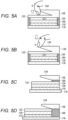
Figs. 5A to 5D are schematic cross-sectional views for describing a pulling operation of the three-dimensional UI portion using the cushion material according to an example of the present invention. -
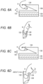
Figs. 6A to 6D are schematic cross-sectional views for describing the pulling operation of the three-dimensional UI portion not using the cushion material according to an example of the present invention. -
Fig. 7 is a view illustrating a flow for determining the pulling operation of the three-dimensional UI portion not using the cushion material according to an example of the present invention. -
Fig. 8 is a schematic cross-sectional view for describing an operation in Step S100 inFig. 7 . -
Figs. 9A and 9B are schematic cross-sectional views for describing an operation of Step S110 inFig. 7 . -
Figs. 10A and 10B are schematic cross-sectional views for describing an operation of Step S120 inFig. 7 . -
Fig. 11 is an exemplary graph for verifying a change in a capacitance when the pulling operation is performed on a three-dimensional UI portion in which the cushioning material is desired to be used by an actual machine. -
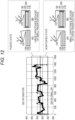
Fig. 12 is an exemplary graph for verifying a change in a capacitance when the three-dimensional UI portion is pressed by the actual machine. - Next, embodiments of the invention will be described. An input display device according to aspects of the present invention provides an interface between a person and a machine. The input display device in the present invention is not particularly limited, but is applied to, for example, an electronic device equipped with a display with a touch panel. The electronic device equipped with the display with the touch panel is, for example, an in-vehicle device having a navigation function, an audio visual function, a television function, and the like.
- Next, examples of the present invention will be described in detail with reference to the drawings.
Fig. 3 is a block diagram illustrating a configuration of an input display device according to an example of the present invention. In the present example, aninput display device 100 includes adisplay 110 that displays an image and a video, acapacitive touch panel 120 mounted on thedisplay 110, a three-dimensional UI portion (or an operation portion) 130 that has one or a plurality of three-dimensional shapes and is attached to the surface of thetouch panel 120, and acontroller 140 that controls image display of thedisplay 110, touch detection of thetouch panel 110, and the like. - The
display 110 is not particularly limited, but includes, for example, a liquid crystal panel or an organic EL panel. Thedisplay 110 displays image data provided from thecontroller 140. For example, an icon representing an input operation of the three-dimensional UI portion 130 is displayed below the three-dimensional UI portion 130. - The
touch panel 120 includes, for example, a plurality of detection units (sensors) formed at positions where a plurality of X-side and Y-side electrode lines intersect. The detection unit changes a capacitance when a finger, a hand, or the like of a user approaches or comes into contact with thetouch panel 110. Thetouch panel 120 is mounted on thedisplay 110 and provides an input interface for the user to make an input to an icon or the like displayed on thedisplay 110. - The
touch panel 120 further includes one or a plurality of three-dimensional UI portions (operation portions) 130 on the surface of a transparent panel. The three-dimensional UI portion 130 has a shape that allows a user to perform a pulling operation with a finger, and includes, for example, a cantilevered pullingportion 134 that pulls (or lifts) an end portion upward as illustrated inFig. 2B . The pullingportion 134 imitates the shape of a power window switch as illustrated inFig. 2A . The number, the size, and the like of the three-dimensional UI portions 130 are not particularly limited. The three-dimensional UI portion 130 is configured such that, when the hand or the finger of the user performs an operation of pulling or lifting the three-dimensional UI portion 130, the capacitance at that position changes. -
Fig. 3 illustrates an example in which four three-dimensional UI portions 130 are attached below thetouch panel 120. The three-dimensional UI portion 130 is configured by using, for example, a transparent material such as acrylic, polycarbonate, or glass. An icon representing an input operation of the user is displayed at a position of thedisplay 110 corresponding to the three-dimensional UI portion 130. However, the entirety of the three-dimensional UI portion 130 does not need to be transparent, and a portion of the three-dimensional UI portion 130, which does not interfere with the icon may be non-transparent. The user visually recognizes the icon displayed below the three-dimensional UI portion 130 and performs an input by performing a pulling operation on the three-dimensional UI portion 130. - Next, an outline of the
input display device 100 in the present example will be described with reference toFigs. 4A to 4D. Fig. 4A illustrates a schematic cross-section of the three-dimensional UI portion 130. As illustrated inFig. 4A , thedisplay 110 is fixed on a product cover (or cover glass or the like) 170, and thetouch panel 120 is mounted on theproduct cover 170. The three-dimensional UI portion 130 is attached to the surface of thetouch panel 120. - The three-
dimensional UI portion 130 includes, for example, abottom surface portion 132 and a pullingportion 134 extending from thebottom surface portion 132 in a cantilever manner. Thebottom surface portion 132 is bonded to a determined position of thetouch panel 120 by using, for example, a double-sided adhesive or the like. The coordinates indicating the attachment position of thebottom surface portion 132 and the shape of thebottom surface portion 132 are registered in thecontroller 140 in advance. For example, when thebottom surface portion 132 has a circular shape, the coordinates of the center and the radius of thebottom surface portion 132 are registered. When thebottom surface portion 132 has a rectangular shape, the coordinates of the intersection point between the diagonal lines and the coordinates of the corner of thebottom surface portion 132 are registered. Furthermore, the height of the pullingportion 134 of the three-dimensional UI portion 130 is also registered. - In the present example, the three-
dimensional UI portion 130 detects a change in a distance (referred to below as a finger distance) to the detection unit (sensor) of thetouch panel 120 from a finger U when the finger U touches the pullingportion 134, and, in this manner, a pulling operation on the pullingportion 134 can be detected. - As illustrated in
Fig. 4A , for example, as in an operation of the power window switch, the finger U is hooked on the end portion of the pullingportion 134, the change in the finger distance D at which the finger U moves away from the touch sensor when the pulling operation is made is detected, and whether or not there is the pulling operation is determined. When the finger distance D increases by the pulling action, the value of the capacitance detected by the touch sensor decreases. Therefore, in the present example, the detection of the pulling operation is realized by implementing a detection structure using acushion material 180 illustrated inFig. 4B in which the change in the finger distance D is likely to occur when pulling is performed with the finger U, and a pulling detection algorithm for detecting the deformation of the finger U at the time of the pulling operation as illustrated inFigs. 4C and 4D . - In the detection structure using the cushion material, the shape, material, size, attachment position, and the like of the cushion material are not particularly limited as long as the finger distance D increases when the user lifts the pulling
portion 134. In the detection structure illustrated inFig. 4B , twocushion materials 180 that are elastically deformable in the vertical direction are attached between both ends of thebottom surface portion 132 of the three-dimensional UI portion 130 and theproduct cover 170. As thecushion material 180, for example, an elastic member such as rubber, spring, sponge, or resin can be used. When the user performs an operation of pulling the pullingportion 134 with the finger U, the three-dimensional UI portion 130 is somewhat lifted upward by thecushion material 180, and a slight distance L is generated between thebottom surface portion 132 and the surface of thetouch panel 120. This changes the finger distance from D to D1 (D < D1), which results in a change in a capacitance for determining whether or not there is a pulling operation. - In the above example, the three-
dimensional UI portion 130 can be separated from thetouch panel 120 in a pulling direction by using thecushion material 180. For example, the pullingportion 134 may be displaced in the pulling direction without using the cushion material by imparting elasticity to the pullingportion 134 itself of the three-dimensional UI portion 130. For example, the width of the cantilevered base portion of the pullingportion 134 may be narrowed or the thickness of the base portion may be thinned to facilitate elastic deformation, or the pullingportion 134 may be made of an elastic material. - Next, the pulling detection algorithm for detecting deformation of the finger will be described.
Fig. 4C illustrates a state in which the finger U has touched the pullingportion 134, and the finger distance at this time is D. When the user hooks the finger U on the pullingportion 134 and lifts the finger U, the shape of the finger is crushed by the stress to be compressed in the pulling direction. As a result, the finger distance changes from D to D2 (D < D2). This change in the finger distance results in the change in the capacitance as much as can detect the pulling operation, and thetouch panel 120 has sensitivity that can detect such a change in the capacitance. - Next, details of the
controller 140 will be described. Thecontroller 140 is electrically connected to thedisplay 110 and thetouch panel 120, and performs image control of thedisplay 110 and touch control of thetouch panel 120. Thecontroller 140 performs overall processing of the input display device, for example, stores data such as a height, a shape, a position, and a video display area of the three-dimensional UI portion 130, performs a display area correction process, performs touch detection and operation determination (touch coordinates detection and detection of the magnitude of the finger distance/capacitance) from an output value of thetouch panel 120, and performs a process of video display/video switching according to the touch detection and operation determination. The processing of thecontroller 140 is performed by hardware and/or software, and is performed by using, for example, a microcontroller including an arithmetic processing unit and a ROM/RAM. - As illustrated in
Fig. 3 , thecontroller 140 includes atouch detection unit 150, anoperation determination unit 160, and adisplay control unit 170. Thetouch detection unit 150 drives the plurality of electrode lines on the X side and/or the Y side of thetouch panel 120, measures the capacitance of each detection unit of the driven electrode line, and provides the measurement result to theoperation determination unit 160. - The
operation determination unit 160 detects a touch operation or a pulling operation on thetouch panel 120 based on the measurement result of thetouch detection unit 150. The touch mentioned here includes not only contact of the finger of the user with thetouch panel 120 but also approach of the finger to thetouch panel 120 at a predetermined distance. For example, when the finger of the user touches or approaches the flat surface of thetouch panel 120, theoperation determination unit 160 determines that the touch operation has been made based on the change in the capacitance of the corresponding detection unit. Similarly, when the finger of the user touches or approaches the three-dimensional UI portion 130, the capacitance of the detection unit corresponding to the three-dimensional UI portion 130 changes, and thus it is determined that the touch operation has been made on the three-dimensional UI portion 130 by the change in the capacitance. - Furthermore, when the touch operation on the three-
dimensional UI portion 130 has been detected, and the capacitance at the touch position is changed within a predetermined time, theoperation determination unit 160 determines whether or not there is the pulling operation from such a change. That is, as illustrated inFigs. 4B and 4D , when the capacitance has changed in response to the change in the finger distance, if the change is equal to or greater than a certain threshold value, theoperation determination unit 160 determines that the pulling operation on the three-dimensional UI portion 130 has been made. When theoperation determination unit 160 determines that the touch operation or the pulling operation has been made, thecontroller 140 provides the input to another electronic device or performs display control or the like corresponding to the input. - The
display control unit 170 displays an image and a video on thedisplay 110, and displays an icon at the corresponding position of the three-dimensional UI portion 130. The icon can be a design representing the input operation of the user. For example, an icon representing the operation of the power window is displayed below the three-dimensional UI portion 130. In addition, thedisplay control unit 170 switches an image to be displayed on thedisplay 120 to another image in response to the determination of theoperation determination unit 160 that the touch operation or the pulling operation has been made. - Next, details of the three-
dimensional UI portion 130 in the present example will be described. First, a method of detecting the finger distance of the three-dimensional UI portion 130 by using the cushion material will be described. In the structure illustrated inFig. 5A , when thecushion material 180 is sandwiched between theproduct cover 170 and thebottom surface portion 132 of the three-dimensional UI portion 130 and the pullingportion 134 is pulled by the finger U, thecushion material 180 stretches in the vertical direction, whereby thebottom surface portion 132 is separated from the surface of thetouch panel 120, the finger distance between thetouch panel 120 and the finger U increases, and the capacitance detected by thetouch panel 120 decreases. When the change in the capacitance is equal to or greater than the threshold value, this is determined as the pulling operation. - On the other hand, as illustrated in
Fig. 5B , contrary to the pulling operation, when the end portion of the pullingportion 134 is pushed by the finger U, thecushion material 180 is compressed in the vertical direction, thebottom surface portion 132 becomes close to the surface of thetouch panel 120, and the finger distance between thetouch panel 120 and the finger U decreases. Thus, the capacitance detected by thetouch panel 120 increases. When the change in the capacitance is equal to or greater than the threshold value, it is determined that this is a pressing pushing operation. - Furthermore, the
cushion material 180 is attached at an appropriate position so that the visibility of the icon to be displayed does not decrease or the degree of freedom of the structure of the three-dimensional UI portion 130 does not decrease. In the three-dimensional UI portion 130 illustrated inFig. 5A , thebottom surface portion 132 and the pullingportion 134 may be integrally molded, or both may be bonded with an adhesive, a double-sided tape, or the like. When thebottom surface portion 132 and the pullingportion 134 are integrally molded or bonded, it is desirable that thecushion material 180 be installed or attached to the outer peripheral portion of the sensor or the icon display of thetouch panel 120. - When the
cushion material 180 is transparent or does not need to be transparent, as illustrated inFig. 5C , thecushion material 180 may be sandwiched and bonded between thebottom surface portion 132 and the pullingportion 134. In this case, the pullingportion 134 changes in a pulling direction or the pressing pushing direction via thecushion material 180, and thebottom surface portion 132 does not change. - Furthermore, in a case of a configuration in which the
bottom surface portion 132 of the three-dimensional UI portion 130 and the pullingportion 134 are not in direct contact with each other or are not bonded to each other, as illustrated inFig. 5D , thecushion material 180 is attached between the pullingportion 134 and theproduct cover 170 on the side portions of thebottom surface portion 132, thetouch panel 120, and thedisplay 110. Also in this case, the pullingportion 134 changes in a pulling direction or the pressing pushing direction via thecushion material 180, and thebottom surface portion 132 does not change. - Next, a method of detecting the finger distance of the three-
dimensional UI portion 130 by not using the cushion material will be described. In a case of a sensor having accuracy enabling detection of a small change in the finger distance (for example, about 2 mm), the pulling operation or the pressing operation can be detected even with a structure not using the cushion material.Figs. 6A and 6B illustrate a state when the finger U has touched the end portion of the pullingportion 134, and the finger distance from the sensor to the finger is D.Figs. 6C and 6D illustrate a state of deformation (crushing) of the finger U when the finger U is pulled even though the finger U is hooked on the end portion of the pullingportion 134. The finger U is deformed by about 2 mm, thereby the finger distance from the sensor to the finger U increases to D2 (D2 > D). - Next,
Fig. 7 illustrates a flow of a determination operation of theoperation determination unit 160 when the cushion material is not used. Theoperation determination unit 160 detects whether or not there is a finger below the pullingportion 134 based on the measurement result of the capacitance by the touch detection unit 150 (S 100). As illustrated inFig. 8 , position coordinates (a portion of an arrow H) when the finger U is hooked on the pullingportion 134 and a threshold value (a portion of an arrow V) of the finger distance/capacitance when there is the finger U under the pullingportion 134 are registered in theoperation determination unit 160 in advance. AlthoughFig. 8 illustrates only the coordinate range in one direction of the arrow H, the coordinate range by the arrow H may be specified as plane coordinates. - The
operation determination unit 160 determines that there is the finger U below the pullingportion 134 when detecting a value that is within the position coordinates indicated by the arrow H and within the threshold value of the capacitance (within the finger distance) indicated by the arrow V based on the measurement result of thetouch detection unit 150. - Then, the
operation determination unit 160 determines a pulling operation based on the change in capacitance (S110).Fig. 9A illustrates a state before the pulling operation, andFig. 9B illustrates a state during the pulling operation. As illustrated inFig. 9B , the finger tip is compressed or crushed by performing the pulling operation, to change the angle of the finger, so that the finger distance changes from D inFig. 9A to D2. As a result, the value of the capacitance detected by the sensor of thetouch panel 120 decreases. Theoperation determination unit 160 determines the pulling operation by detecting the change in the capacitance. - Then, when determining that the pulling operation has been performed, the
operation determination unit 160 determines the end of the pulling operation based on the change in the capacitance (S120).Fig. 10A illustrates a state during the pulling operation, andFig. 10B illustrates a state at the end of the pulling operation. As illustrated inFig. 10B , in an operation to end the pulling operation, the finger is brought back to the original state as opposed to the pulling operation, so that the finger distance changes from D2 inFig. 10A to D. As a result, the value of the capacitance detected by the sensor of thetouch panel 120 increases. Theoperation determination unit 160 determines the end of the pulling operation by detecting the change in the capacitance. - Next, the graph of
Fig. 11 shows the verification result of the change in the capacitance when the pulling operation to the three-dimensional UI portion, which does not use the cushion material, is performed by an actual machine. The vertical axis represents the value of the capacitance, and the horizontal axis represents the number of pieces of detected data. In the actual machine verified this time, the capacitance is detected at 80 fps (frames/second). - As illustrated in the graph of
Fig. 11 , the value of the capacitance when the three-dimensional UI portion 130 is not pulled (when the finger distance is small) is about 1100 or greater, and the value of the capacitance when the three-dimensional UI portion 130 is pulled (when the finger distance is large) decreases to about 800 to 600. Therefore, by setting the threshold value for determining whether or not there is the pulling operation within a range of 800 to 1100 (for example, the threshold value may be set to 950), it is possible to accurately determine whether or not there is the pulling operation. - In addition, the graph of
Fig. 12 shows the verification result of the change in the capacitance when the three-dimensional UI portion is pressed by the actual machine. The vertical axis represents the value of the capacitance, and the horizontal axis represents the number of pieces of detected data. In the actual machine verified this time, the capacitance is detected at 80 fps (frames/second). - Differing from the pulling operation, in the pressing operation, the finger distance does not change due to the crush of the finger. Thus, it is necessary to have a structure in which the finger distance is small at the time of pressing by a configuration (
Fig. 12A ) in which the pullingportion 134 itself of the three-dimensional UI portion 130 is made of a bending material or a configuration (Fig. 12B ) in which thecushion material 180 is sandwiched between the three-dimensional UI portion 130 and the product cover. - In the detection example here, a difference in detection value between the presence and absence of the pushing operation is not as large as that during the pulling operation, but the change in the capacitance during the pushing operation can be read from the graph. For example, it is possible to determine the pressed state or the non-pressed state by setting the threshold value when the value of the capacitance is 325 or greater or 325 or smaller.
- As described above, according to the present example, in the product having the three-dimensional UI, it is possible to accurately detect the pulling operation with a simple structure without increasing the number of touch sensors. As a result, the three-dimensional UI can cope with an operation gesture of the pulling type switch.
- Embodiments of the present invention have been described in detail above. However, the present invention is not limited to these embodiments, and thus various modifications and alterations can be made within the scope of the claims.
-
- 30
- Pulling type switch
- 100
- Input display device
- 110
- Display
- 120
- Touch panel
- 130
- Three-dimensional UI portion (operation portion)
- 132
- Bottom surface portion
- 134
- Pulling portion
- 140
- Controller
Claims (10)
- An input display device (100) comprising:a display (110) configured to display an image;a capacitive touch panel (120) configured to be attached onto the display (110) and include at least one three-dimensional operation portion (130) on a surface of the touch panel (120); anda detection unit configured to detect an operation on the touch panel (120), whereinthe three-dimensional operation portion (130) includes a pulling portion (134) imitating a shape of a pulling type switch (30), andthe detection unit is configured to determine whether or not there is a pulling operation by detecting a change in a capacitance in response to a change in a distance to the touch panel (120) from a finger touching the pulling portion (134).
- The input display device (100) according to claim 1, wherein the operation portion (130) is attached to be separable from the touch panel (120) via an elastic member.
- The input display device (100) according to claim 2, wherein the elastic member is provided between a bottom surface of the operation portion (130) and a fixing portion that supports the display (110).
- The input display device (100) according to claim 2 or 3, wherein the operation portion (130) includes the pulling portion (134) and a bottom surface portion (132) disposed below the pulling portion (134), and the elastic member is provided between the pulling portion (134) and the bottom surface portion (132).
- The input display device (100) according to one of claims 2-4, wherein the operation portion (130) includes the pulling portion (134) and a bottom surface portion (132) disposed below the pulling portion (134), and the elastic member is provided between the pulling portion (134) and a fixing portion that supports the display (110).
- The input display device (100) according to one of claims 1-5, wherein the pulling portion (134) is configured by a member that is elastically deformable in a pulling direction.
- The input display device (100) according to one of claims 1-6, wherein the detection unit is configured to determine that a pulling operation has been performed when a decrease in capacitance of the pulling portion (134) is equal to or greater than a threshold value.
- The input display device (100) according to one of claims 1-7, wherein the detection unit is configured to determine that a pressing operation has been performed when an increase in capacitance of the pulling portion (134) is equal to or greater than a threshold value.
- The input display device (100) according to one of claims 1-8, wherein the detection unit is configured to determine whether or not there is a pulling operation by detecting a change in a capacitance due to a change in a shape of a finger touching the pulling portion (134).
- The input display device (100) according to one of claims 1-9, further comprising: a display unit configured to display an icon representing an input operation at a position corresponding to the operation portion (130) of the display (110).
Applications Claiming Priority (1)
| Application Number | Priority Date | Filing Date | Title |
|---|---|---|---|
| JP2022164522A JP2024057700A (en) | 2022-10-13 | 2022-10-13 | Input display device |
Publications (2)
| Publication Number | Publication Date |
|---|---|
| EP4354263A1 true EP4354263A1 (en) | 2024-04-17 |
| EP4354263B1 EP4354263B1 (en) | 2025-04-16 |
Family
ID=88295619
Family Applications (1)
| Application Number | Title | Priority Date | Filing Date |
|---|---|---|---|
| EP23202015.6A Active EP4354263B1 (en) | 2022-10-13 | 2023-10-06 | Input display device |
Country Status (4)
| Country | Link |
|---|---|
| US (1) | US12056299B2 (en) |
| EP (1) | EP4354263B1 (en) |
| JP (1) | JP2024057700A (en) |
| CN (1) | CN117891365A (en) |
Citations (5)
| Publication number | Priority date | Publication date | Assignee | Title |
|---|---|---|---|---|
| US20140160064A1 (en) * | 2008-01-04 | 2014-06-12 | Tactus Technology, Inc | User interface and methods |
| US20190250740A1 (en) * | 2014-05-15 | 2019-08-15 | Panasonic Intellectual Property Management Co., Ltd. | Operation knob and display device in which same is used |
| JP2020190832A (en) | 2019-05-20 | 2020-11-26 | 株式会社デンソー | Input display device |
| US20220037100A1 (en) * | 2020-07-28 | 2022-02-03 | Methode Electronics, Inc. | Force detecting window lift system |
| US20220253158A1 (en) * | 2019-07-05 | 2022-08-11 | Hap2U | 3d control device for capacitive touch interface |
Family Cites Families (4)
| Publication number | Priority date | Publication date | Assignee | Title |
|---|---|---|---|---|
| TW201508609A (en) * | 2013-08-19 | 2015-03-01 | Wistron Corp | Method of interacting with large display device and related interaction system |
| US11175775B2 (en) * | 2017-10-11 | 2021-11-16 | Mitsubishi Electric Corporation | Input device, touch panel control device, and touch panel control method |
| DE112017008192T5 (en) * | 2017-12-14 | 2020-07-30 | Mitsubishi Electric Corporation | Operator support device, touch panel device and touch panel input system |
| US11003262B2 (en) * | 2018-06-25 | 2021-05-11 | Visteon Global Technologies, Inc. | Input knob for a touch-sensitive surface in a display system |
-
2022
- 2022-10-13 JP JP2022164522A patent/JP2024057700A/en active Pending
-
2023
- 2023-10-06 EP EP23202015.6A patent/EP4354263B1/en active Active
- 2023-10-12 US US18/485,603 patent/US12056299B2/en active Active
- 2023-10-13 CN CN202311324165.XA patent/CN117891365A/en active Pending
Patent Citations (5)
| Publication number | Priority date | Publication date | Assignee | Title |
|---|---|---|---|---|
| US20140160064A1 (en) * | 2008-01-04 | 2014-06-12 | Tactus Technology, Inc | User interface and methods |
| US20190250740A1 (en) * | 2014-05-15 | 2019-08-15 | Panasonic Intellectual Property Management Co., Ltd. | Operation knob and display device in which same is used |
| JP2020190832A (en) | 2019-05-20 | 2020-11-26 | 株式会社デンソー | Input display device |
| US20220253158A1 (en) * | 2019-07-05 | 2022-08-11 | Hap2U | 3d control device for capacitive touch interface |
| US20220037100A1 (en) * | 2020-07-28 | 2022-02-03 | Methode Electronics, Inc. | Force detecting window lift system |
Also Published As
| Publication number | Publication date |
|---|---|
| EP4354263B1 (en) | 2025-04-16 |
| JP2024057700A (en) | 2024-04-25 |
| US12056299B2 (en) | 2024-08-06 |
| CN117891365A (en) | 2024-04-16 |
| US20240126386A1 (en) | 2024-04-18 |
Similar Documents
| Publication | Publication Date | Title |
|---|---|---|
| US10963089B2 (en) | Tactile sensation providing apparatus and tactile sensation providing method | |
| US20100182263A1 (en) | Touchpad assembly with tactile feedback | |
| EP3422156B1 (en) | Control unit for vehicle and control method for the same | |
| CN110413102B (en) | Electronic device and control method for electronic device | |
| CN101107587B (en) | Moving objects presented by a touch input display device | |
| EP1126406A2 (en) | Touch panel input device | |
| WO2006115946A2 (en) | Touch sensitive device and method using pre-touch information | |
| CN105589594A (en) | Electronic apparatus and electronic apparatus operation control method | |
| EP2526471A1 (en) | Touch sensing device, touch screen device comprising the touch sensing device, mobile device, method for sensing a touch and method for manufacturing a touch sensing device | |
| JP4808804B2 (en) | Input device | |
| EP4354263B1 (en) | Input display device | |
| EP4354264A1 (en) | Input display device | |
| EP4394564B1 (en) | Input display device | |
| US9606651B2 (en) | Electronic device | |
| JP2006350789A (en) | Display device with touch panel | |
| EP4383053A1 (en) | Input display device | |
| EP4415264B1 (en) | Input display device | |
| US12585368B2 (en) | Input display device | |
| EP4546095A1 (en) | Input display device | |
| JP2011048815A (en) | Input device | |
| KR101715394B1 (en) | Apparatus with touch window unit | |
| KR20160021939A (en) | Touchscreen providing virtual haptic feedback and terminal having the same |
Legal Events
| Date | Code | Title | Description |
|---|---|---|---|
| PUAI | Public reference made under article 153(3) epc to a published international application that has entered the european phase |
Free format text: ORIGINAL CODE: 0009012 |
|
| STAA | Information on the status of an ep patent application or granted ep patent |
Free format text: STATUS: THE APPLICATION HAS BEEN PUBLISHED |
|
| AK | Designated contracting states |
Kind code of ref document: A1 Designated state(s): AL AT BE BG CH CY CZ DE DK EE ES FI FR GB GR HR HU IE IS IT LI LT LU LV MC ME MK MT NL NO PL PT RO RS SE SI SK SM TR |
|
| STAA | Information on the status of an ep patent application or granted ep patent |
Free format text: STATUS: REQUEST FOR EXAMINATION WAS MADE |
|
| 17P | Request for examination filed |
Effective date: 20241007 |
|
| RBV | Designated contracting states (corrected) |
Designated state(s): AL AT BE BG CH CY CZ DE DK EE ES FI FR GB GR HR HU IE IS IT LI LT LU LV MC ME MK MT NL NO PL PT RO RS SE SI SK SM TR |
|
| GRAP | Despatch of communication of intention to grant a patent |
Free format text: ORIGINAL CODE: EPIDOSNIGR1 |
|
| STAA | Information on the status of an ep patent application or granted ep patent |
Free format text: STATUS: GRANT OF PATENT IS INTENDED |
|
| INTG | Intention to grant announced |
Effective date: 20241118 |
|
| RIC1 | Information provided on ipc code assigned before grant |
Ipc: G06F 3/044 20060101ALN20241108BHEP Ipc: H01H 21/22 20060101ALI20241108BHEP Ipc: G06F 3/039 20130101AFI20241108BHEP |
|
| GRAS | Grant fee paid |
Free format text: ORIGINAL CODE: EPIDOSNIGR3 |
|
| GRAA | (expected) grant |
Free format text: ORIGINAL CODE: 0009210 |
|
| STAA | Information on the status of an ep patent application or granted ep patent |
Free format text: STATUS: THE PATENT HAS BEEN GRANTED |
|
| AK | Designated contracting states |
Kind code of ref document: B1 Designated state(s): AL AT BE BG CH CY CZ DE DK EE ES FI FR GB GR HR HU IE IS IT LI LT LU LV MC ME MK MT NL NO PL PT RO RS SE SI SK SM TR |
|
| P01 | Opt-out of the competence of the unified patent court (upc) registered |
Free format text: CASE NUMBER: APP_11897/2025 Effective date: 20250311 |
|
| REG | Reference to a national code |
Ref country code: GB Ref legal event code: FG4D |
|
| REG | Reference to a national code |
Ref country code: CH Ref legal event code: EP Ref country code: DE Ref legal event code: R096 Ref document number: 602023002949 Country of ref document: DE |
|
| REG | Reference to a national code |
Ref country code: IE Ref legal event code: FG4D |
|
| REG | Reference to a national code |
Ref country code: NL Ref legal event code: MP Effective date: 20250416 |
|
| PG25 | Lapsed in a contracting state [announced via postgrant information from national office to epo] |
Ref country code: NL Free format text: LAPSE BECAUSE OF FAILURE TO SUBMIT A TRANSLATION OF THE DESCRIPTION OR TO PAY THE FEE WITHIN THE PRESCRIBED TIME-LIMIT Effective date: 20250416 |
|
| REG | Reference to a national code |
Ref country code: AT Ref legal event code: MK05 Ref document number: 1786184 Country of ref document: AT Kind code of ref document: T Effective date: 20250416 |
|
| PG25 | Lapsed in a contracting state [announced via postgrant information from national office to epo] |
Ref country code: PT Free format text: LAPSE BECAUSE OF FAILURE TO SUBMIT A TRANSLATION OF THE DESCRIPTION OR TO PAY THE FEE WITHIN THE PRESCRIBED TIME-LIMIT Effective date: 20250818 Ref country code: FI Free format text: LAPSE BECAUSE OF FAILURE TO SUBMIT A TRANSLATION OF THE DESCRIPTION OR TO PAY THE FEE WITHIN THE PRESCRIBED TIME-LIMIT Effective date: 20250416 Ref country code: ES Free format text: LAPSE BECAUSE OF FAILURE TO SUBMIT A TRANSLATION OF THE DESCRIPTION OR TO PAY THE FEE WITHIN THE PRESCRIBED TIME-LIMIT Effective date: 20250416 |
|
| REG | Reference to a national code |
Ref country code: LT Ref legal event code: MG9D |
|
| PG25 | Lapsed in a contracting state [announced via postgrant information from national office to epo] |
Ref country code: NO Free format text: LAPSE BECAUSE OF FAILURE TO SUBMIT A TRANSLATION OF THE DESCRIPTION OR TO PAY THE FEE WITHIN THE PRESCRIBED TIME-LIMIT Effective date: 20250716 Ref country code: GR Free format text: LAPSE BECAUSE OF FAILURE TO SUBMIT A TRANSLATION OF THE DESCRIPTION OR TO PAY THE FEE WITHIN THE PRESCRIBED TIME-LIMIT Effective date: 20250717 |
|
| PG25 | Lapsed in a contracting state [announced via postgrant information from national office to epo] |
Ref country code: PL Free format text: LAPSE BECAUSE OF FAILURE TO SUBMIT A TRANSLATION OF THE DESCRIPTION OR TO PAY THE FEE WITHIN THE PRESCRIBED TIME-LIMIT Effective date: 20250416 |
|
| PG25 | Lapsed in a contracting state [announced via postgrant information from national office to epo] |
Ref country code: BG Free format text: LAPSE BECAUSE OF FAILURE TO SUBMIT A TRANSLATION OF THE DESCRIPTION OR TO PAY THE FEE WITHIN THE PRESCRIBED TIME-LIMIT Effective date: 20250416 |
|
| PG25 | Lapsed in a contracting state [announced via postgrant information from national office to epo] |
Ref country code: HR Free format text: LAPSE BECAUSE OF FAILURE TO SUBMIT A TRANSLATION OF THE DESCRIPTION OR TO PAY THE FEE WITHIN THE PRESCRIBED TIME-LIMIT Effective date: 20250416 |
|
| PG25 | Lapsed in a contracting state [announced via postgrant information from national office to epo] |
Ref country code: AT Free format text: LAPSE BECAUSE OF FAILURE TO SUBMIT A TRANSLATION OF THE DESCRIPTION OR TO PAY THE FEE WITHIN THE PRESCRIBED TIME-LIMIT Effective date: 20250416 |
|
| PG25 | Lapsed in a contracting state [announced via postgrant information from national office to epo] |
Ref country code: RS Free format text: LAPSE BECAUSE OF FAILURE TO SUBMIT A TRANSLATION OF THE DESCRIPTION OR TO PAY THE FEE WITHIN THE PRESCRIBED TIME-LIMIT Effective date: 20250716 |
|
| PG25 | Lapsed in a contracting state [announced via postgrant information from national office to epo] |
Ref country code: IS Free format text: LAPSE BECAUSE OF FAILURE TO SUBMIT A TRANSLATION OF THE DESCRIPTION OR TO PAY THE FEE WITHIN THE PRESCRIBED TIME-LIMIT Effective date: 20250816 |
|
| PG25 | Lapsed in a contracting state [announced via postgrant information from national office to epo] |
Ref country code: LV Free format text: LAPSE BECAUSE OF FAILURE TO SUBMIT A TRANSLATION OF THE DESCRIPTION OR TO PAY THE FEE WITHIN THE PRESCRIBED TIME-LIMIT Effective date: 20250416 |
|
| PGFP | Annual fee paid to national office [announced via postgrant information from national office to epo] |
Ref country code: DE Payment date: 20251021 Year of fee payment: 3 |
|
| PG25 | Lapsed in a contracting state [announced via postgrant information from national office to epo] |
Ref country code: SM Free format text: LAPSE BECAUSE OF FAILURE TO SUBMIT A TRANSLATION OF THE DESCRIPTION OR TO PAY THE FEE WITHIN THE PRESCRIBED TIME-LIMIT Effective date: 20250416 Ref country code: DK Free format text: LAPSE BECAUSE OF FAILURE TO SUBMIT A TRANSLATION OF THE DESCRIPTION OR TO PAY THE FEE WITHIN THE PRESCRIBED TIME-LIMIT Effective date: 20250416 |
|
| PGFP | Annual fee paid to national office [announced via postgrant information from national office to epo] |
Ref country code: FR Payment date: 20251030 Year of fee payment: 3 |
|
| REG | Reference to a national code |
Ref country code: DE Ref legal event code: R097 Ref document number: 602023002949 Country of ref document: DE |
|
| PG25 | Lapsed in a contracting state [announced via postgrant information from national office to epo] |
Ref country code: CZ Free format text: LAPSE BECAUSE OF FAILURE TO SUBMIT A TRANSLATION OF THE DESCRIPTION OR TO PAY THE FEE WITHIN THE PRESCRIBED TIME-LIMIT Effective date: 20250416 |
|
| PG25 | Lapsed in a contracting state [announced via postgrant information from national office to epo] |
Ref country code: EE Free format text: LAPSE BECAUSE OF FAILURE TO SUBMIT A TRANSLATION OF THE DESCRIPTION OR TO PAY THE FEE WITHIN THE PRESCRIBED TIME-LIMIT Effective date: 20250416 |
|
| PG25 | Lapsed in a contracting state [announced via postgrant information from national office to epo] |
Ref country code: SK Free format text: LAPSE BECAUSE OF FAILURE TO SUBMIT A TRANSLATION OF THE DESCRIPTION OR TO PAY THE FEE WITHIN THE PRESCRIBED TIME-LIMIT Effective date: 20250416 |
|
| PG25 | Lapsed in a contracting state [announced via postgrant information from national office to epo] |
Ref country code: IT Free format text: LAPSE BECAUSE OF FAILURE TO SUBMIT A TRANSLATION OF THE DESCRIPTION OR TO PAY THE FEE WITHIN THE PRESCRIBED TIME-LIMIT Effective date: 20250416 |
|
| PLBE | No opposition filed within time limit |
Free format text: ORIGINAL CODE: 0009261 |
|
| STAA | Information on the status of an ep patent application or granted ep patent |
Free format text: STATUS: NO OPPOSITION FILED WITHIN TIME LIMIT |
|
| REG | Reference to a national code |
Ref country code: CH Ref legal event code: L10 Free format text: ST27 STATUS EVENT CODE: U-0-0-L10-L00 (AS PROVIDED BY THE NATIONAL OFFICE) Effective date: 20260225 |
|
| PG25 | Lapsed in a contracting state [announced via postgrant information from national office to epo] |
Ref country code: RO Free format text: LAPSE BECAUSE OF FAILURE TO SUBMIT A TRANSLATION OF THE DESCRIPTION OR TO PAY THE FEE WITHIN THE PRESCRIBED TIME-LIMIT Effective date: 20250416 |
|
| 26N | No opposition filed |
Effective date: 20260119 |