EP4354247B1 - Path planning method for wall-climbing robot - Google Patents
Path planning method for wall-climbing robot Download PDFInfo
- Publication number
- EP4354247B1 EP4354247B1 EP22918129.2A EP22918129A EP4354247B1 EP 4354247 B1 EP4354247 B1 EP 4354247B1 EP 22918129 A EP22918129 A EP 22918129A EP 4354247 B1 EP4354247 B1 EP 4354247B1
- Authority
- EP
- European Patent Office
- Prior art keywords
- wall
- climbing robot
- robot
- distance
- lane changing
- Prior art date
- Legal status (The legal status is an assumption and is not a legal conclusion. Google has not performed a legal analysis and makes no representation as to the accuracy of the status listed.)
- Active
Links
Images


Classifications
-
- G—PHYSICS
- G05—CONTROLLING; REGULATING
- G05D—SYSTEMS FOR CONTROLLING OR REGULATING NON-ELECTRIC VARIABLES
- G05D1/00—Control of position, course, altitude or attitude of land, water, air or space vehicles, e.g. using automatic pilots
- G05D1/02—Control of position or course in two dimensions
- G05D1/021—Control of position or course in two dimensions specially adapted to land vehicles
- G05D1/0212—Control of position or course in two dimensions specially adapted to land vehicles with means for defining a desired trajectory
- G05D1/0214—Control of position or course in two dimensions specially adapted to land vehicles with means for defining a desired trajectory in accordance with safety or protection criteria, e.g. avoiding hazardous areas
-
- G—PHYSICS
- G05—CONTROLLING; REGULATING
- G05D—SYSTEMS FOR CONTROLLING OR REGULATING NON-ELECTRIC VARIABLES
- G05D1/00—Control of position, course, altitude or attitude of land, water, air or space vehicles, e.g. using automatic pilots
- G05D1/60—Intended control result
- G05D1/648—Performing a task within a working area or space, e.g. cleaning
-
- G—PHYSICS
- G05—CONTROLLING; REGULATING
- G05D—SYSTEMS FOR CONTROLLING OR REGULATING NON-ELECTRIC VARIABLES
- G05D1/00—Control of position, course, altitude or attitude of land, water, air or space vehicles, e.g. using automatic pilots
- G05D1/20—Control system inputs
- G05D1/24—Arrangements for determining position or orientation
- G05D1/245—Arrangements for determining position or orientation using dead reckoning
-
- G—PHYSICS
- G05—CONTROLLING; REGULATING
- G05D—SYSTEMS FOR CONTROLLING OR REGULATING NON-ELECTRIC VARIABLES
- G05D1/00—Control of position, course, altitude or attitude of land, water, air or space vehicles, e.g. using automatic pilots
- G05D1/60—Intended control result
- G05D1/656—Interaction with payloads or external entities
- G05D1/678—Interaction with payloads or external entities for tethered vehicles
-
- G—PHYSICS
- G05—CONTROLLING; REGULATING
- G05D—SYSTEMS FOR CONTROLLING OR REGULATING NON-ELECTRIC VARIABLES
- G05D2105/00—Specific applications of the controlled vehicles
- G05D2105/10—Specific applications of the controlled vehicles for cleaning, vacuuming or polishing
-
- G—PHYSICS
- G05—CONTROLLING; REGULATING
- G05D—SYSTEMS FOR CONTROLLING OR REGULATING NON-ELECTRIC VARIABLES
- G05D2107/00—Specific environments of the controlled vehicles
- G05D2107/95—Interior or surroundings of another vehicle
-
- G—PHYSICS
- G05—CONTROLLING; REGULATING
- G05D—SYSTEMS FOR CONTROLLING OR REGULATING NON-ELECTRIC VARIABLES
- G05D2109/00—Types of controlled vehicles
- G05D2109/10—Land vehicles
- G05D2109/15—Climbing vehicles
-
- G—PHYSICS
- G05—CONTROLLING; REGULATING
- G05D—SYSTEMS FOR CONTROLLING OR REGULATING NON-ELECTRIC VARIABLES
- G05D2111/00—Details of signals used for control of position, course, altitude or attitude of land, water, air or space vehicles
- G05D2111/50—Internal signals, i.e. from sensors located in the vehicle, e.g. from compasses or angular sensors
- G05D2111/52—Internal signals, i.e. from sensors located in the vehicle, e.g. from compasses or angular sensors generated by inertial navigation means, e.g. gyroscopes or accelerometers
-
- G—PHYSICS
- G05—CONTROLLING; REGULATING
- G05D—SYSTEMS FOR CONTROLLING OR REGULATING NON-ELECTRIC VARIABLES
- G05D2111/00—Details of signals used for control of position, course, altitude or attitude of land, water, air or space vehicles
- G05D2111/50—Internal signals, i.e. from sensors located in the vehicle, e.g. from compasses or angular sensors
- G05D2111/54—Internal signals, i.e. from sensors located in the vehicle, e.g. from compasses or angular sensors for measuring the travel distances, e.g. by counting the revolutions of wheels
Definitions
- the present application relates to the technical field of wall-climbing robots, and in particular to a path planning method for a wall-climbing robot.
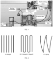
- FIG. 1 is a schematic diagram illustrating a working principle of a robot system.
- a main operation mode of a ship derusting robot is to be safely and reliably adsorbed to a surface of a ship for a derusting operation with a high-pressure water jet module carried.
- this technology is integrated with wall climbing, derusting and recycling, the ship derusting robot needs to carry a high-pressure water pipe, a vacuum recycling pipe and a cable to operate.
- FIG. 2 is a schematic diagram illustrating several types of movement path planning for a wall-climbing robot.
- path planning for the wall-climbing robot mainly includes: straight, N-shaped (Z-shaped) and zigzag path planning.
- a straight crawling trajectory is low in efficiency, the robot can only travel in a straight direction, but cannot crawl back and forth, and for the wall-climbing derusting robot to derust, it will lead to poor consistency at a connection part of a derusting portion and affect the overall derusting quality.
- the robot undergoes a serious tail falling phenomenon, that is, after the robot travels for a period of time, the whole robot will shift downwards for a certain distance, resulting that the robot is unable to operate according to a previously planned path.
- the wall-climbing robot When the wall-climbing robot operates vertically along the wall surface of the ship, with the increase of a climbing height of the robot, the pipe to be dragged correspondingly becomes longer, the gravity of the pipe will increase, and the mass of the load of the robot and a position of its center of gravity will change, resulting in a certain angle deviation of the robot. With the increase of the distance, the deviation value will gradually increase, and manual adjustment is required.
- the lane changing action tests the experience of operators, and the lane changing distance cannot ensure consistency. If the lane changing distance is too small, an overlapping area is caused to be too large and the efficiency is low; and if the lane changing distance is too large, repair missing regions are caused and need to be repaired, and the operation efficiency is reduced.
- the US20100030378 A1 patent document discloses a multi-functional wall climbing robot designed to navigate and perform tasks on vertical and ceiling surfaces of an indoor space.
- the robot employs an IGPS, which consists of navigation transmitters emitting rotating fan beams and a navigation receiver that recognizes these beams as IGPS signals.
- a mobile controller installed on the robot's frame processes these signals to determine the robot's position and control its movement via a drive mechanism.
- the US20130024067A1 patent document discloses a ground vehicle capable of holonomic motion, which allows it to move in any direction while carrying tools such as sensors for non-destructive inspection.
- the vehicle features a frame with four or more Mecanum wheels, each driven by an independently controlled motor, and a plurality of suction devices to maintain precise control on non-level surfaces.
- the CN204772513U patent document discloses a multi-functional robot specifically engineered for performing various tasks on the facades of boats and ships.
- the robot employs magnetic materials to adhere to the vessel's surfaces and features a crawler-type structure for adaptable contact. It is equipped with a stable servo motor system to ensure smooth movement and a rotating operating platform that can accommodate a range of working tools, such as spray guns, welding guns, and cutters.
- the related art only considers the operation in a vertical mode and never considers the operation in a horizontal mode.
- the wall-climbing robot performs horizontal operation along the wall surface of the ship, the robot will undergo the tail falling phenomenon due to the influence of the gravity of the robot itself and the load, and the above problems will be more serious.
- the present application provides a path planning method for a wall-climbing robot.
- the present disclosure mainly solves the problems of path planning, vertical face straight walking and automatic lane changing of the robot, and the robot implements automated operation according to the path planning, vertical face straight walking and automatic lane changing, so that people are freed from frequently operating a remote controller and performing real-time monitoring, and the robot is more intelligent.
- the functions of vertical face straight walking and automatic lane changing of the wall-climbing robot are realized, so that a whole robot system is more automatic and the work efficiency is improved.
- a path planning method for a wall-climbing robot includes following steps:
- the analyzing the crawling capability of the wall-climbing robot in step 3 specifically includes: dividing crawling movement modes of the wall-climbing robot on a wall surface of a ship into a vertical mode and a horizontal mode.
- the vertical mode includes vertical upward movement and vertical downward movement
- the wall-climbing robot in the vertical upward movement needs to overcome a resistance moment caused by the gravity of a body and the gravity of the load of the robot and a resistance moment caused by friction of wheel sets, and when a speed is constant, a resistance moment of the wall-climbing robot in the vertical upward movement is greater than a resistance moment in the downward movement.
- the vertical mode is implemented by following steps:
- the horizontal mode includes horizontal forward movement and horizontal backward movement, and in horizontal movement of the wall-climbing robot, the wall-climbing robot needs to overcome the resistance moment caused by the gravity of the body and the gravity of the load of the wall-climbing robot and the resistance moment caused by the friction of the wheel sets.
- the analyzing the steering capability of the wall-climbing robot in step 3 specifically includes:
- implementation of lane changing by the wall-climbing robot specifically includes:
- the following technical effects can be obtained: compared with the existing path planning, according to the present disclosure, the advantages of Z-shaped (N-shaped) and zigzag path planning are integrated, operation steps for lane changing are reduced, an overlapping region is reduced and the operation efficiency is improved. Above all, the automated operation is realized, and does not rely on the experience of the operator. The tail falling phenomenon is avoided by rotating a certain compensation angle, so that the robot can walk in a horizontal line instead of a previous curve in the horizontal mode, and inside path navigation and automatic lane changing can be better realized.
- the solution of the present disclosure is used for solving the problems above, and by means of the solution, the robot implements automated operation according to path planning, straight walking and automated lane changing, the operator is freed from frequently operating the remote controller and performing real-time monitoring, and the robot is more intelligent.
- a path planning method of the present disclosure includes the following steps.
- Step 1 establishing a spatial pose model of a wall-climbing robot during a working process.
- FIG. 3 is a schematic diagram illustrating a spatial pose model of a wall-climbing robot during a working process, where an OXYZ coordinate system is a ground coordinate system and an OXYZ coordinate system is a ship wall surface coordinate system.
- ⁇ is an included angle between a wall surface of a ship and a vertical plane. According to an actual situation of the wall surface, it can be known that 0 ⁇ 90.
- Step 3 performing kinetics analysis on the wall-climbing robot, and analyzing a crawling capability and a steering capability of the wall-climbing robot.
- Crawling movement modes of the wall-climbing robot on the wall surface of the ship is divided into a vertical mode and a horizontal mode.
- the wall-climbing robot in the vertical upward movement needs to overcome resistance moments in identical directions, that is, a resistance moment caused by the gravity of a body of the robot and the gravity of a load, and a resistance moment caused by friction of the wheel sets; and when the speed is constant, a resistance moment of the wall-climbing robot in the vertical upward movement is greater than a resistance moment in the downward movement.
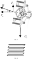
- FIG. 4 is a schematic diagram illustrating stress analysis, where G Z represents a component of a sum of the gravity of the body of the wall-climbing robot and the gravity of the load borne by the wall-climbing robot along a z axis in the OXYZ coordinate system, M represents a friction force of the wheel sets when the wall-climbing robot moves upwards, M' represents a friction force of the wheel sets when the wall-climbing robot moves downwards, F represents a driving force when the wall-climbing robot moves upwards, and F' represents a driving force when the wall-climbing robot moves downwards.
- G Z represents a component of a sum of the gravity of the body of the wall-climbing robot and the gravity of the load borne by the wall-climbing robot along a z axis in the OXYZ coordinate system
- M represents a friction force of the wheel sets when the wall-climbing robot moves upwards
- M' represents a friction force of the wheel sets when the wall-climb
- the wall-climbing robot in the vertical mode, can walk straight only by keeping a crawling angle unchanged.
- the wall-climbing robot is equipped with an inertial measurement unit (IMU) module.
- IMU inertial measurement unit
- the horizontal mode includes horizontal forward movement and horizontal backward movement, and in horizontal movement of the wall-climbing robot, the wall-climbing robot needs to overcome resistance moments in two directions, that is, the resistance moment caused by the gravity of the body of the wall-climbing robot and the gravity of the load, and the resistance moment caused by the friction of the wheel sets.
- G Z represents the component of the sum of the gravity of the body of the wall-climbing robot and the gravity of the load borne by the wall-climbing robot along the z axis in the OXYZ coordinate system
- M represents a friction force of the wheel sets when the wall-climbing robot moves forward
- M' represents a friction force of the wheel sets when the wall-climbing robot moves backward
- F represents a driving force when the wall-climbing robot moves forward
- F' represents a driving force when the wall-climbing robot moves backward.
- FIG. 7 is a schematic diagram illustrating stress analysis of automated operation of a robot after compensation, where Q represents a resultant force of a driving force and a friction force when the robot moves forward, F Z represents a component of the resultant force in the z axis direction, F X represents a component of the resultant force in an x axis direction, and ⁇ is a set offset angle.
- the horizontal mode is technically implemented by the following steps:
- the wall-climbing robot is involved in steering movement during a working process, the action is realized by differential motion of driving wheels of the wall-climbing robot, and sideslip occurs when a driving wheel on one side rotate fast and a driving wheel on the other side rotates slowly, so as to perform the steering movement.
- a rotation speed and a rotation radius of the wall-climbing robot during a steering process are also codetermined by movement directions and speeds of the driving wheels, and the rotation radius directly determines a lane changing distance of the wall-climbing robot.
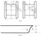
- FIG. 9 is a schematic diagram illustrating steering of wheel sets on two sides of a robot.
- a point a, a point b and a point c are centers of the wheel sets on two sides and the body of the robot respectively, with O 1 representing a center of first steering of the robot and O 2 representing a center of second steering of the robot.
- O 1 representing a center of first steering of the robot
- O 2 representing a center of second steering of the robot.
- v c v a + v b 2
- r v a + v b v a ⁇ v b . B 2 ;
- FIG. 10 is a schematic diagram illustrating lane changing of a robot.
- the implementation of lane changing by the wall-climbing robot specifically includes:
- the advantages of Z-shaped (N-shaped) and zigzag path planning are integrated, operation steps for lane changing are reduced, an overlapping region is reduced and the operation efficiency is improved.
- the automated operation is realized, and does not rely on the experience of the operator.
- the tail falling phenomenon is avoided by rotating a certain compensation angle, so that the robot can walk in a horizontal line instead of a previous curve in the horizontal mode, and inside path navigation and automatic lane changing can be better realized.
Landscapes
- Engineering & Computer Science (AREA)
- Aviation & Aerospace Engineering (AREA)
- Radar, Positioning & Navigation (AREA)
- Remote Sensing (AREA)
- Physics & Mathematics (AREA)
- General Physics & Mathematics (AREA)
- Automation & Control Theory (AREA)
- Control Of Position, Course, Altitude, Or Attitude Of Moving Bodies (AREA)
- Manipulator (AREA)
Description
- The present application relates to the technical field of wall-climbing robots, and in particular to a path planning method for a wall-climbing robot.
- A wall-climbing robot has characteristics of a large load and a heavy body, and often needs to be externally connected with some devices during working.
FIG. 1 is a schematic diagram illustrating a working principle of a robot system. For example, a main operation mode of a ship derusting robot is to be safely and reliably adsorbed to a surface of a ship for a derusting operation with a high-pressure water jet module carried. Meanwhile, since this technology is integrated with wall climbing, derusting and recycling, the ship derusting robot needs to carry a high-pressure water pipe, a vacuum recycling pipe and a cable to operate. -
FIG. 2 is a schematic diagram illustrating several types of movement path planning for a wall-climbing robot. At present, path planning for the wall-climbing robot mainly includes: straight, N-shaped (Z-shaped) and zigzag path planning. A straight crawling trajectory is low in efficiency, the robot can only travel in a straight direction, but cannot crawl back and forth, and for the wall-climbing derusting robot to derust, it will lead to poor consistency at a connection part of a derusting portion and affect the overall derusting quality. Operation with an N-shaped (Z-shaped) trajectory also has the consistency problem at the connection part of the derusting portion, and when the robot operates according to the N-shaped (Z-shaped) trajectory, the robot needs to carry out a large-scale steering operation, so that the efficiency is reduced and high steering performance of the robot needs to be ensured. Although the derusting portion of a zigzag crawling trajectory has a certain overlapping region, the overall derusting quality is good and the derusting efficiency is high. - Due to complex working conditions of a wall surface of the ship, existing path planning solutions for the robot are basically semi-automated operation, that is, in the N-shaped (Z-shaped) path planning, the lane changing action needs manual operation. Meanwhile, when the wall-climbing robot is adsorbed to the wall surface of the ship and travels, the wall-climbing robot will slide down along the wall surface of the ship under the action of the gravity of the robot itself, the gravity of the high-pressure water pipe and the gravity of the recycling pipe. Especially when the wall-climbing robot travels in a horizontal direction, the robot undergoes a serious tail falling phenomenon, that is, after the robot travels for a period of time, the whole robot will shift downwards for a certain distance, resulting that the robot is unable to operate according to a previously planned path.
- When the wall-climbing robot operates vertically along the wall surface of the ship, with the increase of a climbing height of the robot, the pipe to be dragged correspondingly becomes longer, the gravity of the pipe will increase, and the mass of the load of the robot and a position of its center of gravity will change, resulting in a certain angle deviation of the robot. With the increase of the distance, the deviation value will gradually increase, and manual adjustment is required. The lane changing action tests the experience of operators, and the lane changing distance cannot ensure consistency. If the lane changing distance is too small, an overlapping area is caused to be too large and the efficiency is low; and if the lane changing distance is too large, repair missing regions are caused and need to be repaired, and the operation efficiency is reduced.
- The
US20100030378 A1 patent document discloses a multi-functional wall climbing robot designed to navigate and perform tasks on vertical and ceiling surfaces of an indoor space. The robot employs an IGPS, which consists of navigation transmitters emitting rotating fan beams and a navigation receiver that recognizes these beams as IGPS signals. A mobile controller installed on the robot's frame processes these signals to determine the robot's position and control its movement via a drive mechanism. - The
US20130024067A1 patent document discloses a ground vehicle capable of holonomic motion, which allows it to move in any direction while carrying tools such as sensors for non-destructive inspection. The vehicle features a frame with four or more Mecanum wheels, each driven by an independently controlled motor, and a plurality of suction devices to maintain precise control on non-level surfaces. - The
CN204772513U patent document discloses a multi-functional robot specifically engineered for performing various tasks on the facades of boats and ships. The robot employs magnetic materials to adhere to the vessel's surfaces and features a crawler-type structure for adaptable contact. It is equipped with a stable servo motor system to ensure smooth movement and a rotating operating platform that can accommodate a range of working tools, such as spray guns, welding guns, and cutters. - The related art only considers the operation in a vertical mode and never considers the operation in a horizontal mode. When the wall-climbing robot performs horizontal operation along the wall surface of the ship, the robot will undergo the tail falling phenomenon due to the influence of the gravity of the robot itself and the load, and the above problems will be more serious.
- The invention is set out in the appended set of claims. In order to solve the above technical problems, the present application provides a path planning method for a wall-climbing robot. The present disclosure mainly solves the problems of path planning, vertical face straight walking and automatic lane changing of the robot, and the robot implements automated operation according to the path planning, vertical face straight walking and automatic lane changing, so that people are freed from frequently operating a remote controller and performing real-time monitoring, and the robot is more intelligent. With the adoption of this solution, the functions of vertical face straight walking and automatic lane changing of the wall-climbing robot are realized, so that a whole robot system is more automatic and the work efficiency is improved.
- The technical solution adopted in the present application is as follows.
- A path planning method for a wall-climbing robot includes following steps:
- step 1, establishing a spatial pose model of a wall-climbing robot during a working process;
- step 2, performing statics analysis on the wall-climbing robot, and decomposing a resultant force G of gravity of the wall-climbing robot itself and gravity of a load borne by the wall-climbing robot;
- step 3, performing kinetics analysis on the wall-climbing robot, and analyzing a crawling capability and a steering capability of the wall-climbing robot; and
- step 4, performing path planning according to analysis results of the crawling capability and the steering capability.
- Further, the analyzing the crawling capability of the wall-climbing robot in step 3 specifically includes: dividing crawling movement modes of the wall-climbing robot on a wall surface of a ship into a vertical mode and a horizontal mode.
- Further, the vertical mode includes vertical upward movement and vertical downward movement, the wall-climbing robot in the vertical upward movement needs to overcome a resistance moment caused by the gravity of a body and the gravity of the load of the robot and a resistance moment caused by friction of wheel sets, and when a speed is constant, a resistance moment of the wall-climbing robot in the vertical upward movement is greater than a resistance moment in the downward movement.
- Further, the vertical mode is implemented by following steps:
- step 301, manually adjusting the wall-climbing robot to a vertical posture, and recording a current feedback angle α of an inertial measurement unit module; and
- step 302, setting a walking distance and a lane changing distance of the wall-climbing robot, and starting, by the wall-climbing robot, automated operation according to the current feedback angle, with a completed operation area being S*L*N, where S represents the walking distance, L represents the set lane changing distance, and N represents a number of lane changing.
- Further, the horizontal mode includes horizontal forward movement and horizontal backward movement, and in horizontal movement of the wall-climbing robot, the wall-climbing robot needs to overcome the resistance moment caused by the gravity of the body and the gravity of the load of the wall-climbing robot and the resistance moment caused by the friction of the wheel sets.
- Further, in the horizontal mode, due to an influence of gravity GZ, an upward force FZ is needed for compensation; and
- in the horizontal mode, a force balance equation of the wall-climbing robot is as follows:

- where Q represents a resultant force of a driving force and a friction force when the robot moves forward, FZ represents a component of the resultant force in a z axis direction, FX represents a component of the resultant force in an x axis direction, and α is a set offset angle.
- Further, the horizontal mode is technically implemented by following steps:
- step 301', manually adjusting the wall-climbing robot to a horizontal posture, and recording a current feedback angle α1 of the inertial measurement unit module;
- step 302', allowing the wall-climbing robot to move forward the set walking distance S, and recording a current feedback angle α2 of the inertial measurement unit module;
- step 303', calculating a difference between the two angles αf = α2 - α1, and taking αf as an offset angle set for the wall-climbing robot moving forward the distance S;
- step 304', manually adjusting the wall-climbing robot to the horizontal posture corresponding to the feedback angle α1 again;
- step 305', allowing the wall-climbing robot to move backward the set distance S, and recording a current feedback angle α3 of the current inertial measurement unit module;
- step 306', calculating a difference between the two angles αb = α3 -α1, and taking αb as an offset angle set for the wall-climbing robot moving backward the distance S; and
- step 307', performing automated operation, by the wall-climbing robot, according to the offset angles αf and αb measured at two times, with an operation area being S*L*N, where S represents the walking distance of the robot, L represents the set lane changing distance, and N represents the number of lane changing.
- Further, the analyzing the steering capability of the wall-climbing robot in step 3 specifically includes:
- a rotation speed and a rotation radius of the wall-climbing robot during a steering process are codetermined by movement directions and speeds of driving wheels, and the rotation radius directly determines the lane changing distance of the wall-climbing robot;
- when movement directions of two driving wheels are identical, speed directions of wheel sets on two sides are identical, and a rotation center is located on an outer side of the wall-climbing robot; and
- when the movement directions of the two driving wheels are opposite, the speed directions of the wheel sets on the two sides are opposite, and the rotation center is located on an inner side of the wall-climbing robot.
- Further, when the speed directions of the wheel sets on the two sides are identical, a following formula is obtained:

- when the speed directions of the wheel sets on the two sides are opposite, a following formula is obtained:

- where, a point a, a point b and a point c are centers of the wheel sets on the two sides and the body of the wall-climbing robot, r represents a steering radius of the wall-climbing robot, which is half of the lane changing distance L, Va and Vb are speeds of the wheel sets on the two sides of the wall-climbing robot, Vc is a speed of the body of the wall-climbing robot, and B is a distance between the point a and the point b.
- Further, implementation of lane changing by the wall-climbing robot specifically includes:
- calculating the steering radius r of the robot according to the set lane changing distance L, so as to calculate the speeds Va and Vb of the wheel sets on the two sides of the wall-climbing robot for first steering; and
- starting, by the wall-climbing robot, second steering when a rotation angle of the first steering reaches 90 degrees, and rotating 90 degrees again in an opposite direction of the first steering to complete a lane changing action.
- Through the embodiments of the present application, the following technical effects can be obtained: compared with the existing path planning, according to the present disclosure, the advantages of Z-shaped (N-shaped) and zigzag path planning are integrated, operation steps for lane changing are reduced, an overlapping region is reduced and the operation efficiency is improved. Above all, the automated operation is realized, and does not rely on the experience of the operator. The tail falling phenomenon is avoided by rotating a certain compensation angle, so that the robot can walk in a horizontal line instead of a previous curve in the horizontal mode, and inside path navigation and automatic lane changing can be better realized.
- In order to more clearly explain the technical solutions in embodiments of the present application, the following will make a brief introduction to the drawings that need to be used in the description of the embodiments or the related art. Obviously, the drawings in the following description are some of embodiments of the present application, and for those skilled in the art, other figures can also be derived from these figures without creative labor.
-
FIG. 1 is a schematic diagram illustrating a working principle of a robot system. -
FIG. 2 is a schematic diagram illustrating several types of movement path planning for a wall-climbing robot. -
FIG. 3 is a schematic diagram illustrating a spatial pose model of a wall-climbing robot during a working process. -
FIG. 4 is a schematic diagram illustrating stress analysis. -
FIG. 5 is a schematic diagram illustrating a path for a robot to start automated operation according to a current angle. -
FIG. 6 is a schematic diagram illustrating stress analysis of automated operation of a robot. -
FIG. 7 is a schematic diagram illustrating stress analysis of automated operation of a robot after compensation. -
FIG. 8 is a schematic diagram illustrating a path of a robot performing automated operation according to an offset angle. -
FIG. 9 is a schematic diagram illustrating steering of wheel sets on two sides of a robot. -
FIG. 10 is a schematic diagram illustrating lane changing of a robot. - In order to make the purposes, technical solutions and advantages of embodiments of the present application clearer, the technical solutions in the embodiments of the present application will be described clearly and completely below in conjunction with the accompanying drawings of the present application. Apparently, the embodiments described are some embodiments of the present application, but not all of embodiments. Based on the embodiments of the present application, all other embodiments obtained by those skilled in the art without involving any creative labor are within the scope of protection of the present application.
- Since a traditional robot is controlled by an operator using a wireless remote controller to control the movement, lane changing and straight walking of the robot and the operator is required to continuously operate the robot in the whole operation process of the robot, the time and energy of personnel are greatly consumed and the labor cost is increased. The solution of the present disclosure is used for solving the problems above, and by means of the solution, the robot implements automated operation according to path planning, straight walking and automated lane changing, the operator is freed from frequently operating the remote controller and performing real-time monitoring, and the robot is more intelligent.
- A path planning method of the present disclosure includes the following steps.
- Step 1, establishing a spatial pose model of a wall-climbing robot during a working process.
-
FIG. 3 is a schematic diagram illustrating a spatial pose model of a wall-climbing robot during a working process, where an OXYZ coordinate system is a ground coordinate system and an OXYZ coordinate system is a ship wall surface coordinate system. InFIG. 3 , β is an included angle between a wall surface of a ship and a vertical plane. According to an actual situation of the wall surface, it can be known that 0 ≤β≤ 90. - Step 2, performing statics analysis on the wall-climbing robot, and decomposing a resultant force G of gravity of the wall-climbing robot and gravity of a load borne by the wall-climbing robot to obtain components as follows:

- Step 3, performing kinetics analysis on the wall-climbing robot, and analyzing a crawling capability and a steering capability of the wall-climbing robot.
- Crawling movement modes of the wall-climbing robot on the wall surface of the ship is divided into a vertical mode and a horizontal mode.
- Where, the vertical mode includes vertical upward movement and vertical downward movement, the wall-climbing robot in the vertical upward movement needs to overcome resistance moments in identical directions, that is, a resistance moment caused by the gravity of a body of the robot and the gravity of a load, and a resistance moment caused by friction of the wheel sets; and when the speed is constant, a resistance moment of the wall-climbing robot in the vertical upward movement is greater than a resistance moment in the downward movement.
-
FIG. 4 is a schematic diagram illustrating stress analysis, where GZ represents a component of a sum of the gravity of the body of the wall-climbing robot and the gravity of the load borne by the wall-climbing robot along a z axis in the OXYZ coordinate system, M represents a friction force of the wheel sets when the wall-climbing robot moves upwards, M' represents a friction force of the wheel sets when the wall-climbing robot moves downwards, F represents a driving force when the wall-climbing robot moves upwards, and F' represents a driving force when the wall-climbing robot moves downwards. - According to the stress analysis in
FIG. 4 , in the vertical mode, the wall-climbing robot can walk straight only by keeping a crawling angle unchanged. The wall-climbing robot is equipped with an inertial measurement unit (IMU) module. - The vertical mode is implemented by the following steps:
- step 301, manually adjusting the wall-climbing robot to a vertical posture, and recording a current feedback angle α of the IMU module; and
- step 302, setting a walking distance and a lane changing distance of the wall-climbing robot, and starting, by the wall-climbing robot, automated operation according to the current feedback angle, with a completed operation area being S*L*N; where S represents the walking distance, L represents the set lane changing distance, and N represents a number of lane changing.
FIG. 5 is a schematic diagram illustrating a path for a robot to start automated operation according to a current angle. - The horizontal mode includes horizontal forward movement and horizontal backward movement, and in horizontal movement of the wall-climbing robot, the wall-climbing robot needs to overcome resistance moments in two directions, that is, the resistance moment caused by the gravity of the body of the wall-climbing robot and the gravity of the load, and the resistance moment caused by the friction of the wheel sets.
FIG. 6 is a schematic diagram illustrating stress analysis of automated operation of a robot, where GZ represents the component of the sum of the gravity of the body of the wall-climbing robot and the gravity of the load borne by the wall-climbing robot along the z axis in the OXYZ coordinate system, M represents a friction force of the wheel sets when the wall-climbing robot moves forward, M' represents a friction force of the wheel sets when the wall-climbing robot moves backward, F represents a driving force when the wall-climbing robot moves forward, and F' represents a driving force when the wall-climbing robot moves backward. - According to the stress analysis in
FIG. 6 , in the horizontal mode, due to the influence of the gravity GZ, the robot undergoes a tail falling phenomenon during crawling, and the degree of tail falling when moving forward is different from the degree of tail falling when moving backward. Therefore, an upward force FZ is needed for compensation to balance the influence of GZ, and the following technical implementation solution is proposed. -
FIG. 7 is a schematic diagram illustrating stress analysis of automated operation of a robot after compensation, where Q represents a resultant force of a driving force and a friction force when the robot moves forward, FZ represents a component of the resultant force in the z axis direction, FX represents a component of the resultant force in an x axis direction, and α is a set offset angle. - According to the stress analysis in
FIG. 7 , a force balance equation of the robot can be listed as follows:
- In a practical situation, working conditions of each ship are different, and a value of α is directly influenced by a paint film material, a corrosion degree, marine life and various types of iron rust. Therefore, during an actual operation, it is necessary to measure the value of α in advance.
- The horizontal mode is technically implemented by the following steps:
- step 301', manually adjusting the wall-climbing robot to a horizontal posture, and recording a current feedback angle α1 of the IMU module;
- step 302', allowing the wall-climbing robot to move forward the set walking distance S, and recording a current feedback angle α2 of the IMU module;
- step 303', calculating a difference between the two angles αf = α2- α1, and taking αf as an offset angle set for the wall-climbing robot moving forward the distance S;
- step 304', manually adjusting the wall-climbing robot to the horizontal posture corresponding to the feedback angle α1 again;
- step 305', allowing the wall-climbing robot to move backward the set distance S, and recording a current feedback angle α3 of the current IMU module;
- step 306', calculating a difference between the two angles αb = α3 -α1, and taking αb as an offset angle set for the wall-climbing robot moving backward the distance S; and
- step 307', performing automated operation, by the wall-climbing robot, according to the offset angles αf and αb measured at two times, with an operation area being S*L*N, where S represents the walking distance of the robot, L represents the set lane changing distance, and N represents the number of lane changing.
FIG. 8 is a schematic diagram illustrating a path of a robot performing automated operation according to an offset angle. - When the above solution is realized, the wall-climbing robot is involved in steering movement during a working process, the action is realized by differential motion of driving wheels of the wall-climbing robot, and sideslip occurs when a driving wheel on one side rotate fast and a driving wheel on the other side rotates slowly, so as to perform the steering movement. A rotation speed and a rotation radius of the wall-climbing robot during a steering process are also codetermined by movement directions and speeds of the driving wheels, and the rotation radius directly determines a lane changing distance of the wall-climbing robot. When movement directions of two driving wheels are identical, speed directions of wheel sets on two sides are identical, and a rotation center is located on an outer side of the wall-climbing robot; and when the movement directions of the two driving wheels are opposite, the speed directions of the wheel sets on the two sides are opposite, and the rotation center is located on an inner side of the wall-climbing robot.
-
FIG. 9 is a schematic diagram illustrating steering of wheel sets on two sides of a robot. InFIG. 9 , a point a, a point b and a point c are centers of the wheel sets on two sides and the body of the robot respectively, with O1 representing a center of first steering of the robot and O2 representing a center of second steering of the robot. As shown in the left part ofFIG. 9 , when the speed directions of the wheel sets on the two sides are identical, the following formula is obtained:
- when the speed directions of the wheel sets on the two sides are opposite, the following formula is obtained:

- where, the point a, the point b and the point c are the centers of the wheel sets on the two sides and the body of the wall-climbing robot, r represents a steering radius of the wall-climbing robot, which is half of the lane changing distance L, Va and Vb are speeds of the wheel sets on the two sides of the wall-climbing robot, Vc is a speed of the body of the wall-climbing robot, and B is a distance between the point a and the point b.
-
FIG. 10 is a schematic diagram illustrating lane changing of a robot. The implementation of lane changing by the wall-climbing robot specifically includes: - calculating the steering radius r of the robot according to the set lane changing distance L, so as to calculate the speeds Va and Vb of the wheel sets on the two sides of the wall-climbing robot for first steering; and
- starting, by the wall-climbing robot, second steering when a rotation angle of the first steering reaches 90 degrees, and rotating 90 degrees again in an opposite direction of the first steering to complete a lane changing action.
- According to the present disclosure, the advantages of Z-shaped (N-shaped) and zigzag path planning are integrated, operation steps for lane changing are reduced, an overlapping region is reduced and the operation efficiency is improved. Above all, the automated operation is realized, and does not rely on the experience of the operator. The tail falling phenomenon is avoided by rotating a certain compensation angle, so that the robot can walk in a horizontal line instead of a previous curve in the horizontal mode, and inside path navigation and automatic lane changing can be better realized.
Claims (4)
- A path planning method for a wall-climbing robot, the method comprises following steps:step 1, establishing a spatial pose model of a wall-climbing robot during a working process;step 2, performing statics analysis on the wall-climbing robot, and decomposing a resultant force G of gravity of the wall-climbing robot itself and gravity of a load borne by the wall-climbing robot;step 3, performing kinetics analysis on the wall-climbing robot, and analyzing a crawling capability and a steering capability of the wall-climbing robot; andstep 4, performing path planning according to analysis results of the crawling capability and the steering capability;characterized in that the analyzing the steering capability of the wall-climbing robot in step 3 specifically comprises:codetermining a rotation speed and a rotation radius of the wall-climbing robot during a steering process by movement directions and speeds of driving wheels, wherein the rotation radius directly determines a lane changing distance of the wall-climbing robot;when movement directions of two driving wheels are identical, speed directions of wheel sets on two sides are identical, and a rotation center is located on an outer side of the wall-climbing robot;when the movement directions of the two driving wheels are opposite, the speed directions of the wheel sets on the two sides are opposite, and the rotation center is located on an inner side of the wall-climbing robot;when the speed directions of the wheel sets on the two sides are identical, a following formula is obtained:
 when the speed directions of the wheel sets on the two sides are opposite, a following formula is obtained:
 wherein, a point a, a point b and a point c are centers of the wheel sets on the two sides and a body of the wall-climbing robot, r represents a steering radius of the wall-climbing robot, which is half of the lane changing distance L, Va and Vb are speeds of the wheel sets on the two sides of the wall-climbing robot, Vc is a speed of the body of the wall-climbing robot, and B is a distance between the point a and the point b;wherein implementation of lane changing by the wall-climbing robot specifically comprises:calculating the steering radius r of the robot according to the set lane changing distance L, so as to calculate the speeds Va and Vb of the wheel sets on the two sides of the wall-climbing robot for first steering; andstarting, by the wall-climbing robot, second steering when a rotation angle of the first steering reaches 90 degrees, and rotating 90 degrees again in an opposite direction of the first steering to complete a lane changing action;wherein the analyzing the crawling capability of the wall-climbing robot in step 3 specifically comprises: dividing crawling movement modes of the wall-climbing robot on a wall surface of a ship into a vertical mode and a horizontal mode;wherein the vertical mode is implemented by following steps:step 301, manually adjusting the wall-climbing robot to a vertical posture, and recording a current feedback angle α of an inertial measurement unit module; andstep 302, setting a walking distance and the lane changing distance of the wall-climbing robot, and starting, by the wall-climbing robot, automated operation according to the current feedback angle, with a completed operation area being S*L*N, where S represents the walking distance, L represents the set lane changing distance, and N represents a number of lane changing;wherein the horizontal mode is technically implemented by following steps:step 301', manually adjusting the wall-climbing robot to a horizontal posture, and recording a current feedback angle α1 of the inertial measurement unit module;step 302', allowing the wall-climbing robot to move forward the set walking distance S, and recording a current feedback angle α2 of the inertial measurement unit module;step 303', calculating a difference between the two angles αf = α2 - α1, and taking αf as an offset angle set for the wall-climbing robot moving forward the distance S;step 304', manually adjusting the wall-climbing robot to the horizontal posture corresponding to the feedback angle α1 again;step 305', allowing the wall-climbing robot to move backward the set distance S, and recording a current feedback angle α3 of the current inertial measurement unit module;step 306', calculating a difference between the two angles αb = α3 -α1, and taking αb as an offset angle set for the wall-climbing robot moving backward the distance S; andstep 307', performing automated operation, by the wall-climbing robot, according to the offset angles αf and αb measured at two times, with an operation area being S*L*N, where S represents the walking distance of the robot, L represents the set lane changing distance, and N represents the number of lane changing.
 - The method of claim 1, wherein the vertical mode comprises vertical upward movement and vertical downward movement; the wall-climbing robot in the vertical upward movement needs to overcome a resistance moment caused by the gravity of the body and the gravity of the load of the robot and a resistance moment caused by friction of the wheel sets; and when the speed is constant, a resistance moment of the wall-climbing robot in the vertical upward movement is greater than a resistance moment in the downward movement.
- The method of claim 1, wherein the horizontal mode comprises horizontal forward movement and horizontal backward movement; and in horizontal movement of the wall-climbing robot, the wall-climbing robot needs to overcome a resistance moment caused by the gravity of the body and the gravity of the load of the wall-climbing robot and a resistance moment caused by friction of the wheel sets.
- The method of claim 1, wherein in the horizontal mode, due to an influence of gravity GZ, an upward force FZ is needed for compensation; andin the horizontal mode, a force balance equation of the wall-climbing robot is as follows:
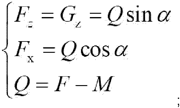 where Q represents a resultant force of a driving force and a friction force when the robot moves forward, FZ represents a component of the resultant force in a z axis direction, FX represents a component of the resultant force in an x axis direction, a is a set offset angle, M represents a friction force of the wheel set when the wall-climbing robot moves forward, and F represents a driving force when the wall-climbing robot moves forward.
Applications Claiming Priority (2)
| Application Number | Priority Date | Filing Date | Title |
|---|---|---|---|
| CN202210000699.6A CN114019986B (en) | 2022-01-04 | 2022-01-04 | Path planning method of wall-climbing robot |
| PCT/CN2022/098581 WO2023130673A1 (en) | 2022-01-04 | 2022-06-14 | Path planning method for wall-climbing robot |
Publications (4)
| Publication Number | Publication Date |
|---|---|
| EP4354247A1 EP4354247A1 (en) | 2024-04-17 |
| EP4354247A4 EP4354247A4 (en) | 2024-09-18 |
| EP4354247C0 EP4354247C0 (en) | 2025-04-23 |
| EP4354247B1 true EP4354247B1 (en) | 2025-04-23 |
Family
ID=80069432
Family Applications (1)
| Application Number | Title | Priority Date | Filing Date |
|---|---|---|---|
| EP22918129.2A Active EP4354247B1 (en) | 2022-01-04 | 2022-06-14 | Path planning method for wall-climbing robot |
Country Status (3)
| Country | Link |
|---|---|
| EP (1) | EP4354247B1 (en) |
| CN (1) | CN114019986B (en) |
| WO (1) | WO2023130673A1 (en) |
Families Citing this family (9)
| Publication number | Priority date | Publication date | Assignee | Title |
|---|---|---|---|---|
| CN114019986B (en) * | 2022-01-04 | 2022-05-20 | 北京史河科技有限公司 | Path planning method of wall-climbing robot |
| CN114578820B (en) * | 2022-03-02 | 2024-05-07 | 上海核工程研究设计院股份有限公司 | A method for controlling the trajectory of a wall-climbing robot for nuclear power plant inspection |
| CN115793433B (en) * | 2023-01-06 | 2023-05-05 | 北京史河科技有限公司 | Robot downslide correction control method, downslide correction chassis and robot |
| CN116752816B (en) * | 2023-06-15 | 2026-01-06 | 星迈创新科技(苏州)有限公司 | A control method and storage medium for a pool robot |
| CN117434938B (en) * | 2023-07-31 | 2025-02-18 | 南通中远海运船务工程有限公司 | A ship cleaning intelligent control system and control method thereof |
| CN117001664A (en) * | 2023-08-09 | 2023-11-07 | 河北工业大学 | An anti-overturning detection and control method for a facade mobile robotic arm system |
| CN119002477B (en) * | 2024-07-31 | 2025-05-27 | 哈尔滨工业大学 | An intelligent stair climbing method for a stair climbing robot based on deformable wheels |
| CN120066054B (en) * | 2025-04-25 | 2025-07-18 | 深圳逐际动力科技有限公司 | Method and device for controlling a two-wheeled and footed robot through high obstacles based on deep reinforcement learning, and method for training a motion control model |
| CN120395844A (en) * | 2025-05-14 | 2025-08-01 | 大唐保定热电厂 | A robotic automation platform for on-site intelligent maintenance of water-cooled walls |
Family Cites Families (21)
| Publication number | Priority date | Publication date | Assignee | Title |
|---|---|---|---|---|
| KR100812724B1 (en) * | 2006-09-29 | 2008-03-12 | 삼성중공업 주식회사 | Wall mobile robot using indoor positioning system |
| US8738226B2 (en) * | 2011-07-18 | 2014-05-27 | The Boeing Company | Holonomic motion vehicle for travel on non-level surfaces |
| CN203019367U (en) * | 2012-12-13 | 2013-06-26 | 浙江大学 | Magnetic wheel type wall-climbing robot with curved surface self-adaptive adsorption function |
| CN204772513U (en) * | 2015-05-18 | 2015-11-18 | 浙江理工大学 | Multi -functional robot of crawling of boats and ships facade operation |
| KR101815394B1 (en) * | 2015-10-27 | 2018-01-05 | 한국과학기술원 | Mechanism and Control Method of the Wall-Climbing Aerial Robot |
| CN106437581B (en) * | 2015-11-14 | 2019-08-23 | 西安旭丰科技发展有限责任公司 | A kind of large traction crawl device of hydraulic-driven mode |
| CN105365912B (en) * | 2015-12-18 | 2017-10-20 | 哈尔滨科能熔敷科技有限公司 | A kind of climbing robot of boiler water wall overlay Multipoint synchronous thickness measuring |
| CN105935272B (en) * | 2016-06-21 | 2018-11-06 | 深圳市博飞航空科技有限公司 | A kind of creep control method and system for climbing wall device |
| CN208085842U (en) * | 2017-07-31 | 2018-11-13 | 广东省智能制造研究所 | A kind of crawler-type wall climbing robot |
| WO2019128521A1 (en) * | 2017-12-27 | 2019-07-04 | 杭州高越科技有限公司 | Underwater cleaning robot and crawling method thereof, motion path planning method and system |
| CN108413976A (en) * | 2018-01-23 | 2018-08-17 | 大连理工大学 | A kind of climbing robot intelligence paths planning method and system towards multi-state |
| KR102581198B1 (en) * | 2018-04-16 | 2023-09-22 | 한국전자통신연구원 | Apparatus for pedestrian dead reckoning using shoe model and method for the same |
| CN108655135A (en) * | 2018-07-02 | 2018-10-16 | 洛阳圣瑞智能机器人有限公司 | Ship, petrochemical industry storage tank wall surface climb wall rust removing robot work system |
| US11007635B2 (en) * | 2018-07-25 | 2021-05-18 | The Boeing Company | Gravity compensation for self-propelled robotic vehicles crawling on non-level surfaces |
| CN110667719B (en) * | 2019-10-16 | 2021-11-30 | 山东交通学院 | Marine omnidirectional movement wall climbing robot |
| CN112720451B (en) * | 2019-10-28 | 2021-12-03 | 深圳市行知行机器人技术有限公司 | Automatic operation robot and control method thereof for automatic operation according to planned path |
| CN110850879A (en) * | 2019-11-20 | 2020-02-28 | 蒋念恒 | Automatic cruising operation method of wall-climbing robot |
| CN112045679B (en) * | 2020-08-21 | 2022-05-10 | 上海核工程研究设计院有限公司 | An anti-overturning control method for a wall-climbing robot |
| CN113467461B (en) * | 2021-07-13 | 2022-04-01 | 燕山大学 | Man-machine cooperation type path planning method under mobile robot unstructured environment |
| CN113844221B (en) * | 2021-09-26 | 2024-02-02 | 西北工业大学 | An amphibious three-mode flying adsorption wall-climbing robot and its control method |
| CN114019986B (en) * | 2022-01-04 | 2022-05-20 | 北京史河科技有限公司 | Path planning method of wall-climbing robot |
-
2022
- 2022-01-04 CN CN202210000699.6A patent/CN114019986B/en active Active
- 2022-06-14 WO PCT/CN2022/098581 patent/WO2023130673A1/en not_active Ceased
- 2022-06-14 EP EP22918129.2A patent/EP4354247B1/en active Active
Also Published As
| Publication number | Publication date |
|---|---|
| EP4354247C0 (en) | 2025-04-23 |
| EP4354247A1 (en) | 2024-04-17 |
| EP4354247A4 (en) | 2024-09-18 |
| WO2023130673A1 (en) | 2023-07-13 |
| CN114019986B (en) | 2022-05-20 |
| CN114019986A (en) | 2022-02-08 |
Similar Documents
| Publication | Publication Date | Title |
|---|---|---|
| EP4354247A1 (en) | Path planning method for wall-climbing robot | |
| EP2734343B1 (en) | Movable platform | |
| CN114281083B (en) | Unmanned ship water quality monitoring Internet of things control system and method based on hybrid path planning autonomous navigation | |
| CN107584501B (en) | Live cleaning robot for substation equipment and control method thereof | |
| CN113021382B (en) | Full-automatic intelligent spraying robot | |
| CN113459099A (en) | Ship body weld joint polishing robot and using method thereof | |
| WO2022252220A1 (en) | Precise stopping system and method for multi-axis flatbed vehicle | |
| CN114811265A (en) | A pipeline detection device and system | |
| CN117988848A (en) | Deep-sea manipulator and hydraulic collection integrated intelligent suspended mining equipment | |
| CN115562097A (en) | Intelligent control system of crawler-type hydraulic excavator upper and lower non-ladder plate vehicle | |
| CN112379675B (en) | Sanitation robot control method and system and sanitation robot | |
| CN114610048B (en) | Robot based on fork-type rocker-wheel-leg composite obstacle-crossing mechanism and autonomous obstacle-crossing method | |
| CN112882475A (en) | Motion control method and device of Mecanum wheel type omnibearing mobile robot | |
| CN114296454B (en) | An adaptive motion control method and system for an omnidirectional and omni-drive mobile robot | |
| Akizono et al. | Development on walking robot for underwater inspection | |
| CN117302372B (en) | Multi-stage crawler swing arm type unmanned obstacle surmounting robot and obstacle surmounting method | |
| US12448754B2 (en) | Load based tracking assist | |
| CN109460038A (en) | A kind of inertial navigation heavy duty AGV system and its control method | |
| CN116149173A (en) | An offshore platform jacket cleaning robot and its control method | |
| CN116952944A (en) | Device and method for detecting and identifying weld defects of ship body | |
| CN117449388B (en) | Construction site leveling operation method and system based on laser guidance and excavator | |
| CN120742902B (en) | Wall climbing path control method, system and application of magnetic wall climbing device | |
| CN221698854U (en) | Crawler robot capable of independently building map and navigating | |
| JPH0786768B2 (en) | Driving controller for unmanned vehicles | |
| Liu et al. | Design and implementation of a welding robot for high-altitude column welds |
Legal Events
| Date | Code | Title | Description |
|---|---|---|---|
| STAA | Information on the status of an ep patent application or granted ep patent |
Free format text: STATUS: THE INTERNATIONAL PUBLICATION HAS BEEN MADE |
|
| PUAI | Public reference made under article 153(3) epc to a published international application that has entered the european phase |
Free format text: ORIGINAL CODE: 0009012 |
|
| STAA | Information on the status of an ep patent application or granted ep patent |
Free format text: STATUS: REQUEST FOR EXAMINATION WAS MADE |
|
| 17P | Request for examination filed |
Effective date: 20240112 |
|
| AK | Designated contracting states |
Kind code of ref document: A1 Designated state(s): AL AT BE BG CH CY CZ DE DK EE ES FI FR GB GR HR HU IE IS IT LI LT LU LV MC MK MT NL NO PL PT RO RS SE SI SK SM TR |
|
| REG | Reference to a national code |
Ref legal event code: R079 Free format text: PREVIOUS MAIN CLASS: G05D0001020000 Ref country code: DE Ref legal event code: R079 Ref document number: 602022013720 Country of ref document: DE Free format text: PREVIOUS MAIN CLASS: G05D0001020000 Ipc: G05D0001000000 |
|
| STAA | Information on the status of an ep patent application or granted ep patent |
Free format text: STATUS: EXAMINATION IS IN PROGRESS |
|
| A4 | Supplementary search report drawn up and despatched |
Effective date: 20240816 |
|
| RIC1 | Information provided on ipc code assigned before grant |
Ipc: G05D 1/648 20240101ALI20240809BHEP Ipc: G05D 111/50 20240101ALI20240809BHEP Ipc: G05D 109/15 20240101ALI20240809BHEP Ipc: G05D 107/00 20240101ALI20240809BHEP Ipc: G05D 105/10 20240101ALI20240809BHEP Ipc: G05D 1/678 20240101ALI20240809BHEP Ipc: G05D 1/245 20240101ALI20240809BHEP Ipc: G05D 1/00 20240101AFI20240809BHEP |
|
| 17Q | First examination report despatched |
Effective date: 20240828 |
|
| GRAP | Despatch of communication of intention to grant a patent |
Free format text: ORIGINAL CODE: EPIDOSNIGR1 |
|
| STAA | Information on the status of an ep patent application or granted ep patent |
Free format text: STATUS: GRANT OF PATENT IS INTENDED |
|
| RIC1 | Information provided on ipc code assigned before grant |
Ipc: G05D 1/648 20240101ALI20241128BHEP Ipc: G05D 111/50 20240101ALI20241128BHEP Ipc: G05D 109/15 20240101ALI20241128BHEP Ipc: G05D 107/00 20240101ALI20241128BHEP Ipc: G05D 105/10 20240101ALI20241128BHEP Ipc: G05D 1/678 20240101ALI20241128BHEP Ipc: G05D 1/245 20240101ALI20241128BHEP Ipc: G05D 1/00 20240101AFI20241128BHEP |
|
| DAV | Request for validation of the european patent (deleted) | ||
| DAX | Request for extension of the european patent (deleted) | ||
| INTG | Intention to grant announced |
Effective date: 20241217 |
|
| GRAS | Grant fee paid |
Free format text: ORIGINAL CODE: EPIDOSNIGR3 |
|
| GRAA | (expected) grant |
Free format text: ORIGINAL CODE: 0009210 |
|
| STAA | Information on the status of an ep patent application or granted ep patent |
Free format text: STATUS: THE PATENT HAS BEEN GRANTED |
|
| AK | Designated contracting states |
Kind code of ref document: B1 Designated state(s): AL AT BE BG CH CY CZ DE DK EE ES FI FR GB GR HR HU IE IS IT LI LT LU LV MC MK MT NL NO PL PT RO RS SE SI SK SM TR |
|
| REG | Reference to a national code |
Ref country code: GB Ref legal event code: FG4D |
|
| REG | Reference to a national code |
Ref country code: CH Ref legal event code: EP |
|
| REG | Reference to a national code |
Ref country code: DE Ref legal event code: R096 Ref document number: 602022013720 Country of ref document: DE |
|
| REG | Reference to a national code |
Ref country code: IE Ref legal event code: FG4D |
|
| U01 | Request for unitary effect filed |
Effective date: 20250520 |
|
| U07 | Unitary effect registered |
Designated state(s): AT BE BG DE DK EE FI FR IT LT LU LV MT NL PT RO SE SI Effective date: 20250527 |
|
| U20 | Renewal fee for the european patent with unitary effect paid |
Year of fee payment: 4 Effective date: 20250619 |
|
| PG25 | Lapsed in a contracting state [announced via postgrant information from national office to epo] |
Ref country code: ES Free format text: LAPSE BECAUSE OF FAILURE TO SUBMIT A TRANSLATION OF THE DESCRIPTION OR TO PAY THE FEE WITHIN THE PRESCRIBED TIME-LIMIT Effective date: 20250423 |
|
| PG25 | Lapsed in a contracting state [announced via postgrant information from national office to epo] |
Ref country code: NO Free format text: LAPSE BECAUSE OF FAILURE TO SUBMIT A TRANSLATION OF THE DESCRIPTION OR TO PAY THE FEE WITHIN THE PRESCRIBED TIME-LIMIT Effective date: 20250723 Ref country code: GR Free format text: LAPSE BECAUSE OF FAILURE TO SUBMIT A TRANSLATION OF THE DESCRIPTION OR TO PAY THE FEE WITHIN THE PRESCRIBED TIME-LIMIT Effective date: 20250724 |
|
| PG25 | Lapsed in a contracting state [announced via postgrant information from national office to epo] |
Ref country code: PL Free format text: LAPSE BECAUSE OF FAILURE TO SUBMIT A TRANSLATION OF THE DESCRIPTION OR TO PAY THE FEE WITHIN THE PRESCRIBED TIME-LIMIT Effective date: 20250423 |
|
| PG25 | Lapsed in a contracting state [announced via postgrant information from national office to epo] |
Ref country code: HR Free format text: LAPSE BECAUSE OF FAILURE TO SUBMIT A TRANSLATION OF THE DESCRIPTION OR TO PAY THE FEE WITHIN THE PRESCRIBED TIME-LIMIT Effective date: 20250423 |
|
| PG25 | Lapsed in a contracting state [announced via postgrant information from national office to epo] |
Ref country code: RS Free format text: LAPSE BECAUSE OF FAILURE TO SUBMIT A TRANSLATION OF THE DESCRIPTION OR TO PAY THE FEE WITHIN THE PRESCRIBED TIME-LIMIT Effective date: 20250723 |
|
| PG25 | Lapsed in a contracting state [announced via postgrant information from national office to epo] |
Ref country code: IS Free format text: LAPSE BECAUSE OF FAILURE TO SUBMIT A TRANSLATION OF THE DESCRIPTION OR TO PAY THE FEE WITHIN THE PRESCRIBED TIME-LIMIT Effective date: 20250823 |
|
| U1N | Appointed representative for the unitary patent procedure changed after the registration of the unitary effect |
Representative=s name: SANTARELLI; FR |
|
| PG25 | Lapsed in a contracting state [announced via postgrant information from national office to epo] |
Ref country code: SM Free format text: LAPSE BECAUSE OF FAILURE TO SUBMIT A TRANSLATION OF THE DESCRIPTION OR TO PAY THE FEE WITHIN THE PRESCRIBED TIME-LIMIT Effective date: 20250423 |
|
| PG25 | Lapsed in a contracting state [announced via postgrant information from national office to epo] |
Ref country code: CZ Free format text: LAPSE BECAUSE OF FAILURE TO SUBMIT A TRANSLATION OF THE DESCRIPTION OR TO PAY THE FEE WITHIN THE PRESCRIBED TIME-LIMIT Effective date: 20250423 |
|
| PG25 | Lapsed in a contracting state [announced via postgrant information from national office to epo] |
Ref country code: SK Free format text: LAPSE BECAUSE OF FAILURE TO SUBMIT A TRANSLATION OF THE DESCRIPTION OR TO PAY THE FEE WITHIN THE PRESCRIBED TIME-LIMIT Effective date: 20250423 |
|
| REG | Reference to a national code |
Ref country code: CH Ref legal event code: H13 Free format text: ST27 STATUS EVENT CODE: U-0-0-H10-H13 (AS PROVIDED BY THE NATIONAL OFFICE) Effective date: 20260127 |
|
| PG25 | Lapsed in a contracting state [announced via postgrant information from national office to epo] |
Ref country code: MC Free format text: LAPSE BECAUSE OF FAILURE TO SUBMIT A TRANSLATION OF THE DESCRIPTION OR TO PAY THE FEE WITHIN THE PRESCRIBED TIME-LIMIT Effective date: 20250423 |
|
| PLBE | No opposition filed within time limit |
Free format text: ORIGINAL CODE: 0009261 |
|
| STAA | Information on the status of an ep patent application or granted ep patent |
Free format text: STATUS: NO OPPOSITION FILED WITHIN TIME LIMIT |
|
| REG | Reference to a national code |
Ref country code: CH Ref legal event code: L10 Free format text: ST27 STATUS EVENT CODE: U-0-0-L10-L00 (AS PROVIDED BY THE NATIONAL OFFICE) Effective date: 20260304 |
|
| 26N | No opposition filed |
Effective date: 20260126 |
|
| PG25 | Lapsed in a contracting state [announced via postgrant information from national office to epo] |
Ref country code: IE Free format text: LAPSE BECAUSE OF NON-PAYMENT OF DUE FEES Effective date: 20250614 |
|
| PG25 | Lapsed in a contracting state [announced via postgrant information from national office to epo] |
Ref country code: CH Free format text: LAPSE BECAUSE OF NON-PAYMENT OF DUE FEES Effective date: 20250630 |